

Page 1

Vipersat Circuit Scheduler v3.7.x
ArrangeLink
User Guide
Part Number MN/22135 Revision 1
Page 2

Page 3

Vipersat Circuit Scheduler v3.7.x
ArrangeLink
User Guide
Part Number MN/22135
Document Revision 1
Software version 3.7.2
January 22, 2010
Page 4

COMTECH EF DATA
VIPERSAT Network Products Group
3215 Skyway Court
Fremont, CA 94539
USA
Phone: (510) 252-1462
Fax: (510) 252-1695
www.comtechefdata.com
Part Number: MN/22135
Revision: 1
Software Version: 3.7.2
©2010 by Comtech EF Data, Inc. All rights reserved. No part of this manual may
be copied or reproduced without prior written permission of Comtech EF Data,
Inc.
All products, names, and services are trademarks or registered trademarks of
their respective companies.
Comtech reserves the right to revise this publication at any time without
obligation to provide notification of such revision. Comtech periodically revises
and improves its products and therefore the information in this document is
subject to change without prior notice. Comtech makes no warranty of any kind
with regard to this material, including but limited to the implied warranties of
merchantability and fitness for a particular purpose. No responsibility for any
errors or omissions that may pertain to the material herein is assumed.
Comtech makes no commitment to update nor to keep current the information
contained in this document.
Printed in the United States of America
Page 5

Document Revision History
Revision Date Description
0 7/13/07 Initial Release.
Note: This new document part number, MN/22135, supercedes the previous
VCS User Guide part number, 22135.
New functionality in v1.3.5: VMS N:1 Redundancy.
This version has been upgraded to work with VMS version 3.5.x, in both single
and redundant server configurations.
1 1/22/10 New functionality in v3.7.2: VMS Web Services Client.
This version of Vipersat Circuit Scheduler is now fully integrated into the VMS
code base. Out-of-Band switching and Forward Path switching are not
supported. Analysis Report feature is removed.
Page 6

{ This Page Intentionally Blank }
Page 7

Table of Contents
Chapter 1
General
How to Use This Manual . . . . . . . . . . . 1-1
Manual Organization . . . . . . . . . . . . 1-1
Chapter 1 — General . . . . . . . . . . 1-1
Chapter 2 — Installation . . . . . . . . . 1-1
Chapter 3 — Using ArrangeLink. . . . . 1-2
Appendix A — Glossary . . . . . . . . . 1-2
Conventions and References . . . . . . . . 1-2
Product Description . . . . . . . . . . . . . . 1-3
Introduction . . . . . . . . . . . . . . . . . 1-3
ArrangeLink Main Features . . . . . . . . . 1-3
Schedule Setup . . . . . . . . . . . . . 1-3
Supported Circuit Types . . . . . . . 1-3
Schedule Tag . . . . . . . . . . . . . 1-3
Contention Verification. . . . . . . . . . 1-4
Schedule View . . . . . . . . . . . . . 1-4
Schedule View Details . . . . . . . . 1-5
Schedule Operations . . . . . . . . . . 1-5
Schedule Execution . . . . . . . . . . 1-5
Time Zone Auto-Adjustment . . . . . . 1-5
System Requirements . . . . . . . . . . . 1-5
ArrangeLink and VMS . . . . . . . . . . . . 1-6
New in this Release (v3.7.2) . . . . . . . . 1-6
VMS Web Services Client . . . . . . . . 1-6
Event Priority . . . . . . . . . . . . . .1-6
Customer Support . . . . . . . . . . . . . . 1-7
Contact Information . . . . . . . . . . . 1-7
Return Material Authorization . . . . . . 1-7
Reader Comments / Corrections . . . . 1-7
Chapter 2
Installation
General . . . . . . . . . . . . . . . . . . . . 2-1
Server Preparation . . . . . . . . . . . . . . 2-3
Server Prerequisites . . . . . . . . . . . . 2-3
IIS and ASP.NET . . . . . . . . . . . . . . 2-3
Uninstall Previous Version . . . . . . . . . 2-7
Remove ArrangeLink or VCS . . . . . . 2-7
Remove VMS SOAP Server. . . . . . . 2-7
Remove VMS . . . . . . . . . . . . . . 2-7
Install VMS . . . . . . . . . . . . . . . . . 2-8
Installation Procedure. . . . . . . . . . . . . . 2-9
Install SOAP Services . . . . . . . . . . . 2-9
Install ArrangeLink Web Application . . . 2-12
Server Configuration . . . . . . . . . . . . . 2-18
Set Up Log On Account . . . . . . . . . 2-18
Set Users Security . . . . . . . . . . . . 2-19
Configure Firewall . . . . . . . . . . . . 2-21
Verifying Installation . . . . . . . . . . . . . 2-22
Chapter 3
Using ArrangeLink
General . . . . . . . . . . . . . . . . . . . . . 3-1
Accessing ArrangeLink . . . . . . . . . . . . . 3-3
SOAP Server . . . . . . . . . . . . . . 3-3
Local/Remote PC . . . . . . . . . . . . 3-3
Log In . . . . . . . . . . . . . . . . . . 3-3
Introduction . . . . . . . . . . . . . . . . . . . 3-5
Schedule Setup . . . . . . . . . . . . . . . . 3-7
Schedule Setup Sub-Screens . . . . . . 3-8
Generic Options . . . . . . . . . . . . . . 3-8
Schedule Name . . . . . . . . . . . . . 3-9
Time Zone Profile . . . . . . . . . . . . 3-9
First Occurrence . . . . . . . . . . . . 3-9
Exclusion Profile . . . . . . . . . . . . 3-9
Max. Execution Delay . . . . . . . . . 3-9
Schedule Tag . . . . . . . . . . . . . . 3-9
Scheduling Options . . . . . . . . . . . . 3-10
Schedule Type . . . . . . . . . . . . 3-10
Valid Date Range . . . . . . . . . . . 3-10
Each Occurrence . . . . . . . . . . . 3-11
Recurrence . . . . . . . . . . . . . . 3-12
Daily . . . . . . . . . . . . . . . . 3-13
Weekly . . . . . . . . . . . . . . . 3-13
Monthly . . . . . . . . . . . . . . . 3-13
Circuit Specific Options . . . . . . . . . . 3-14
Circuit Type . . . . . . . . . . . . . . 3-15
InBand Circuit . . . . . . . . . . . . 3-16
Out-of-Band Circuit . . . . . . . . . 3-16
Point-to-Point Out-of-Band . . . . . 3-17
Point-to-Point InBand . . . . . . . . 3-17
Point-to-MultiPoint Out-of-Band . . . 3-19
Point-to-MultiPoint InBand . . . . . 3-19
ToC i
Page 8

Upstream Switch . . . . . . . . . . 3-21
Advanced Switching . . . . . . . . . . . 3-22
Schedule View . . . . . . . . . . . . . . . . 3-25
Schedule Instances . . . . . . . . . . . . 3-26
Past schedules . . . . . . . . . . . . 3-27
Schedules . . . . . . . . . . . . . . . . . 3-28
Selected Schedule Details . . . . . . . . 3-30
Schedule Instances Details . . . . . . 3-30
Schedules Details . . . . . . . . . . . 3-31
Admin . . . . . . . . . . . . . . . . . . . . . 3-33
About . . . . . . . . . . . . . . . . . . . . . 3-34
Appendix A
Glossary
. . . . . . . . . . . . . . . . . . . . . .A-1
Index
. . . . . . . . . . . . . . . . . . . Index-1
ii ArrangeLink User Guide
Page 9

List of Figures
Chapter 1 Figures
Figure 1-1 ArrangeLink Schedules View . . . . . 1-4
Chapter 2 Figures
Figure 2-1 VMS Web Services Components . . 2-1
Figure 2-2 Add/Remove Windows Components2-4
Figure 2-3 Configure Windows Application Server
2-5
Figure 2-4 DefaultAppPool, IIS Manager . . . . . 2-6
Figure 2-5 DefaultAppPool Identity. . . . . . . . . . 2-6
Figure 2-6 Remove ArrangeLink Program . . . . 2-7
Figure 2-7 VMS SOAP Server Setup Wizard . . 2-9
Figure 2-8 Choose Start Menu Folder . . . . . . 2-10
Figure 2-9 VMS SOAP Server Configuration . 2-10
Figure 2-10 SOAP Server Installation Complete .
2-11
Figure 2-11 Services Control Manager, VMS Web
Services . . . . . . . . . . . . . . . . . . . . . . . . 2-12
Figure 2-12 ArrangeLink Program Files . . . . . 2-13
Figure 2-13 Welcome, Setup Wizard . . . . . . . 2-13
Figure 2-14 License Agreement, Setup Wizard . .
2-14
Figure 2-15 Select Installation Address, Setup
Wizard . . . . . . . . . . . . . . . . . . . . . . . . . 2-14
Figure 2-16 Select Disk Drive, Setup Wizard . 2-15
Figure 2-17 Confirm Installation, Setup Wizard . .
2-15
Figure 2-18 Installation Progress, Setup Wizard .
2-16
Figure 2-19 Installation Complete, Setup Wizard .
2-17
Figure 2-20 Account Set Up, VMS Web Services
2-18
Figure 2-21 AL Directory, Properties Command .
2-19
Figure 2-22 Security Permissions, AL Properties.
2-20
Figure 2-23 Add a Port dialog. . . . . . . . . . . . . 2-21
Figure 2-24 Disable Pop-up Blocker. . . . . . . . 2-22
Figure 2-25 Log In dialog . . . . . . . . . . . . . . . . 2-23
Figure 2-26 ArrangeLink Introduction Screen. 2-24
Chapter 3 Figures
Figure 3-1 ArrangeLink Log In Prompt . . . . . . .3-4
Figure 3-2 Log In Failure . . . . . . . . . . . . . . . . .3-4
Figure 3-3 Introduction Screen . . . . . . . . . . . . .3-5
Figure 3-4 Command Bar . . . . . . . . . . . . . . . . .3-5
Figure 3-5 Synchronization with VMS. . . . . . . .3-7
Figure 3-6 Successful Synchronization Message .
3-7
Figure 3-7 Schedule Setup, Generic Options Tab
3-8
Figure 3-8 Schedule Setup, Scheduling Options
Tab. . . . . . . . . . . . . . . . . . . . . . . . . . . .3-10
Figure 3-9 Calendar Selection, Start Date . . .3-11
Figure 3-10 Time Selection, Each Occurrence3-12
Figure 3-11 Duration Parameter, Alert Message .
3-12
Figure 3-12 Daily Schedule Type . . . . . . . . . .3-13
Figure 3-13 Weely Schedule Type . . . . . . . . .3-13
Figure 3-14 Monthly Schedule Type. . . . . . . . 3-14
Figure 3-15 Schedule Setup, Circuit Specific
Options Tab . . . . . . . . . . . . . . . . . . . . .3-15
Figure 3-16 InBand Circuit diagram . . . . . . . . 3-16
Figure 3-17 Out-of-Band Circuit diagram . . . . 3-17
Figure 3-18 Point-to-Point InBand Circuit, Point
One . . . . . . . . . . . . . . . . . . . . . . . . . . .3-18
Figure 3-19 Point-to-Point InBand Circuit, Point
Two . . . . . . . . . . . . . . . . . . . . . . . . . . .3-19
Figure 3-20 Point-to-Multipoint InBand Transmitter
3-20
Figure 3-21 Point-to-Mulitpoint InBand Receivers
3-21
Figure 3-22 Remove Receiver from List . . . . .3-21
Figure 3-23 Upstream Switch, Remote Selection .
3-22
Figure 3-24 Schedule Setup, Advanced Switching
Tab. . . . . . . . . . . . . . . . . . . . . . . . . . . .3-23
Figure 3-25 Schedule View, Schedule Instances
Tab. . . . . . . . . . . . . . . . . . . . . . . . . . . .3-25
Figure 3-26 Schedule Listing Table . . . . . . . .3-26
Figure 3-27 Schedule View, Schedules Tab. . 3-28
Figure 3-28 Schedules Tag Filter Parameter . 3-29
Figure 3-29 Schedule View, Details for Schedule
Instance . . . . . . . . . . . . . . . . . . . . . . . .3-30
Figure 3-30 Schedule View, Details for Schedule
LoF iii
Page 10

3-32
Figure 3-31 Admin Screen, VMS Tab. . . . . . . 3-33
Figure 3-32 Successful Synch with VMS . . . . 3-33
Figure 3-33 About ArrangeLink dialog . . . . . . 3-34
iv ArrangeLink User Guide
Page 11

GENERAL
How to Use This Manual
This manual documents the features and functions of the Vipersat ArrangeLink
Circuit Scheduler software application, and guides the user in how to install and
use this product in a Vipersat network.
Network administrators and operators responsible for the configuration, operation, and maintenance of the Vipersat satellite network are the intended audiences for this document.
C
HAPTER
Manual Organization
This User Guide is organized into the following sections:
Chapter 1 — General
Contains ArrangeLink product description, customer support information, and
manual conventions and references.
Chapter 2 — Installation
Covers the steps for installing the ArrangeLink software application on a web
client PC workstation.
Chapter 1 - General 1-1
Page 12
How to Use This Manual
Chapter 3 — Using ArrangeLink
Describes using ArrangeLink in conjuction with the Vipersat Management
System (VMS) to schedule and establish satellite network circuits automatically.
Appendix A — Glossary
A glossary of terms that pertain to Vipersat satellite network technology.
Conventions and References
The following conventions are utilized in this manual to assist the reader:
NOTE
Note: Provides important information relevant to the accompanying
text.
Tip: Provides complementary information that facilitates the
associated actions or instructions.
Caution: Provides explanatory text that notifies the reader of
possible consequences of an action.
Warning: Provides precautionary text that describes a potentially
hazardous situation. Failure to take or avoid a specified
action may result in damage to equipment.
The following documents are referenced in this manual, and provide supplementary information for the reader:
• Vipersat Management System User Guide (Part Number MN/22156).
1-2 ArrangeLink User Guide
Page 13

Product Description
Introduction
ArrangeLink is a satellite communication scheduling system used to schedule
network resources in support of a variety of critical applications including
distance learning, telemedicine, video conferencing, news and sporting event
video streaming, and scheduled broadcasting.
Using ArrangeLink, all users of the satellite network have visibility of both
current and future network traffic including the network resources required by
each scheduled use.
Both hardware and time resource conflicts are flagged automatically by
ArrangeLink, allowing users to negotiate for resource allocation.
Each version of ArrangeLink is tailored to work with a specific version of the
Vipersat Management System (VMS); it will not operate with prior or later
versions of VMS. For that reason, these two applications are released together.
ArrangeLink Main Features
Product Description
Schedule Setup
Schedules—onetime and recurring—are set up based on the Circuit Type, Start/
End Date/Time, Transmission Data Rate, Transmitter Node, and Receiver
Node. The recurrence setting is a powerful feature of the scheduler. Choices are
for Daily, Weekly, and Monthly occurrences.
The Advanced Switching feature allows a specified modulation and FEC code
rate to be incorporated into the scheduled switch, as well as assigning a Priority
to the event.
Supported Circuit Types
The scheduler provides circuit type choices for InBand Point-to-Point or Pointto-MultiPoint, and UpStream Switch.
Schedule Tag
In addition to the schedule name, one or more Schedule Tags can be defined and
attached to the schedule, providing an expanded range for filtering and finding a
particular event or set of events.
Chapter 1 - General 1-3
Page 14
Product Description
Contention Verification
The system verifies the contention between schedules to make sure the new
schedule is a valid one. Items of contention include Bandwidth and Hardware
resources.
Schedule View
All schedules can be viewed either on a per instance basis or on a per name
basis. Each of these views is controlled using a filter. The filter includes search
fields such as:
• Circuit Type
• Start/End Date/Time
• Status
• Schedule Tag
Figure 1-1
ArrangeLink Schedules View
The contents of a schedule table include:
• Schedule Name
• Type
• Circuit Type
• Start/End Date/Time and Duration
1-4 ArrangeLink User Guide
Page 15

Product Description
Recurrence
•
• Status
Schedule View Details
Schedule details that can be viewed include assigned circuit:
• Channel, Data Rate, and Priority
• Frequency and Bandwidth
• Transmitter site and Receiver site(s)
• Mod/Demod Device list
• Power and Eb/No
Schedule Operations
Users are allowed to stop a Running schedule immediately, or change the End
Date/Time. A Pending schedule can be deleted, modified, or started immediately.
Schedule Execution
Schedules are executed according to the detail requirement of the schedule, such
as participating Nodes, Data Rate, Start/End Date/Time, and Circuit Type. All
participating Nodes will be initiated, and satellite links will be established
accordingly.
Time Zone Auto-Adjustment
When the local Date/Time (Pacific/Eastern/Greenwich) is input for the schedule, the system saves it as Universal Time Coordinates (UTC) Date and Time.
When data is retrieved from the server, such as with schedule view, the local
Date/Time is displayed for the client, regardless of location.
System Requirements
Please refer to the Release Notes (on the application CD) corresponding to this
version of ArrangeLink for the recommended system requirement specifications.
Chapter 1 - General 1-5
Page 16

Product Description
ArrangeLink and VMS
ArrangeLink shares functionality with the VMS to create a seamless operating
environment to control and manage a satellite communications system. This
combination provides the system operator and user with system management
and operation controls for all aspects of satellite communication system operation.
Using the real-time system configuration information from the VMS, the scheduler is able to display current network operating conditions and resource availability. At the time a scheduled event starts, any of the equipment required to
establish the new circuit that are currently in STDMA mode will be automatically switched to SCPC mode, and remain in this mode for the duration of the
event. At the conclusion of the event, the modem units that were used during the
scheduled event are automatically switched back to their home states and once
again become available resources under VMS management.
ArrangeLink works with either the VMS installed on a single stand-alone
server, or with the VMS installed in the optional N:1 server redundancy configuration.
New in this Release (v3.7.2)
VMS Web Services Client
This version of Vipersat Circuit Scheduler is now fully integrated into the VMS
code base. The VMS Web Services SOAP (Simple Object Access Protocol)
Server offering provides an interface for VMS client applications such as
ArrangeLink for communications with the VMS. The SOAP interface runs on a
web services proxy server that also hosts the web applications using Internet
Information Services (IIS). The user interface for these applications is accessed
using a web browser from a client PC workstation.
For more information on VMS Web Services, including the SOAP Server
installation procedure, refer to the VMS User Guide (Part Number MN/22156).
Event Priority
In previous versions of the Circuit Scheduler, an event created in the scheduler
would always supercede any ongoing event that was in contention with the
scheduled event. This is no longer the case. A priority attribute is now assigned
to the scheduled event, and contention will be resolved by granting precedence
to the event which has the higher priority.
1-6 ArrangeLink User Guide
Page 17

Customer Support
Contact Information
Contact Comtech Vipersat Network Products Customer Support for information
or assistance with product support, service, or training on any Vipersat product.
Mail: 3215 Skyway Court
Phone: 1+510-252-1462
Fax: 1+510-252-1695
Email: supportcvni@comtechefdata.com
Web: www.comtechefdata.com
Return Material Authorization
Any equipment or product returned to Vipersat must have a Return Material
Authorization (RMA) issued prior to return. To return a Comtech Vipersat
Networks product for repair or replacement:
Customer Support
Fremont, CA 94539
USA
• Obtain an RMA form and number from Vipersat Customer Support.
• Be prepared to supply the product model number and serial number of the
unit or product.
• To ensure safe shipping of the product, pack the item in the original
shipping carton.
Reader Comments / Corrections
If the reader would like to submit any comments or corrections regarding this
manual and its contents, please forward them to a Comtech Vipersat Customer
Support representative. All input is appreciated.
Chapter 1 - General 1-7
Page 18

Customer Support
{ This Page is Intentionally Blank }
1-8 ArrangeLink User Guide
Page 19
INSTALLATION
C
General
The ArrangeLink Circuit Scheduler application software can be installed on any
workstation that will function as a web server and is either the host for the VMS
Web Services (SOAP Server) or is local to the server that performs that function. This web server workstation must be local to the VMS Server.
C
HAPTER
The SOAP interface runs on a web services proxy server that hosts the web
applications—such as ArrangeLink and VNO—using Internet Information
Services (IIS). The user interface for these applications is accessed using a web
browser from a client PC workstation.
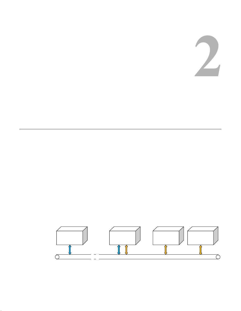
The network component diagram shown in figure 2-1 reflects the recommended
configuration for implementing the VMS Web Services. To minimize latency
issues, the host platform for these services should be on the same LAN as the
VMS Server. Should a network web server be locally available, it would serve
as a logical platform for the SOAP server, as shown in the diagram.
Web Client
P
HTTP/HTML RPC
* Note: the Web Client PC can be local or remote
Figure 2-1
Chapter 2 - Installation 2-1
SOAPServer
(Web Server)
Ethernet LAN
VMS Web Services Components
VMSClient
PC
VMSServer
Page 20

General
If there is no local web server available to host these services, then the following alternative configurations can be utilized:
• If the VMS is standalone, then the VMS Server can host the Web
services and applications.
• If the VMS is redundant, then another local server must host the Web
services and applications in order to retain true redundancy.
Requests and responses transmitted between the web application and the web
service use SOAP over HTTP protocol. The SOAP request is translated into an
RPC call into the VOS and the response is then returned to the web application.
This response is transformed into HTML and sent back to a web browser that
presents the user interface to the operator.
2-2 ArrangeLink User Guide
Page 21

Server Preparation
Server Prerequisites
Prior to installing the ArrangeLink Web service, the following items are
required for the host server:
• Microsoft Windows Server 2003 operating system, with current Service
Pack.
• Microsoft Internet Information Services (IIS), current version, to provide
Web server capabilities over an intranet, the Internet, or an extranet. This
allows client PC workstations to access the web services locally and
remotely.
• Microsoft ASP.NET, current version.
• Full VMS Core program.
• If a firewall is installed on the server, it must be turned off or set correctly
to allow HTTP.
• The SOAP server must be on the same LAN and have either direct access
or an Ethernet connection to the VMS server(s).
Server Preparation
• The SOAP server must be on the same domain as the VMS server(s).
• The installer must have administrator privileges on the server.
Caution: Running SOAP Services on a machine enables that machine to act
as an HTML server which may increase its vulnerability when
connected to the Internet.
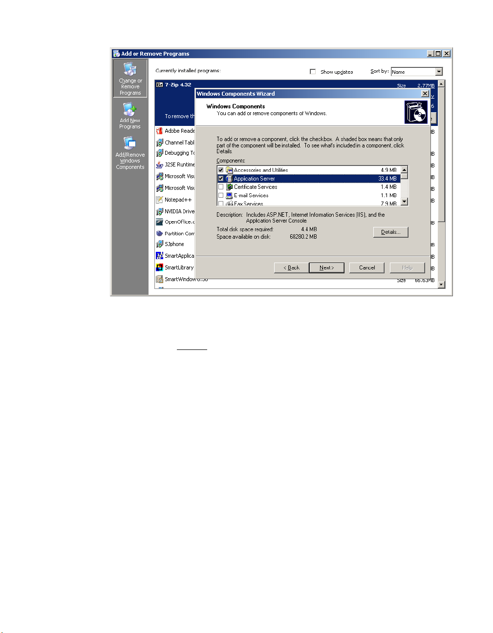
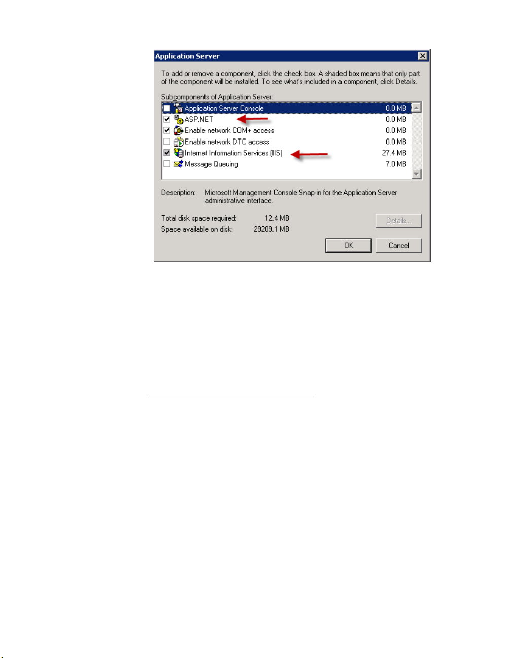
IIS and ASP.NET
Verify that Internet Information Services (IIS) and ASP.NET are installed and
activated (checked):
1. From the Start menu, open the Add or Remove Programs control panel.
Click on the Add/Remove Windows Components button in the left panel
of the window.
The Windows Components Wizard window will open (figure 2-2)
Chapter 2 - Installation 2-3
Page 22
Server Preparation
Figure 2-2
Add/Remove Windows Components
2. Click on Application Server and ensure that the check box is checked, then
click on the Details
button.
The Application Server window will open.
3. Ensure that the check boxes for ASP.NET and IIS are as shown in figure 2-3,
below.
2-4 ArrangeLink User Guide
Page 23
Server Preparation
Figure 2-3
Configure Windows Application Server
4. Click on the OK button in the Application Server window to confirm the
selections.
5. Click on the Next button in the Windows Components Wizard window to
execute the component installations.
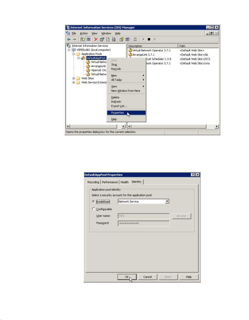
Set the IIS Default Application Pool Identity
1. Open the Internet Information Services (IIS) Manager from
Administrative Tools.
:
2. In the left window panel, expand the local computer tree view down to
DefaultAppPool and select the Properties command from the drop-down
menu (figure 2-4).
Chapter 2 - Installation 2-5
Page 24
Server Preparation
Figure 2-4
DefaultAppPool, IIS Manager
3. Open the Identity tab in the Properties dialog, select the Predefined Network Service, then click OK, as shown in figure 2-5.
Figure 2-5
2-6 ArrangeLink User Guide
DefaultAppPool Identity
Page 25
Server Preparation
Uninstall Previous Version
If a previous version of VMS Web Services or VCS is installed on the server
workstation, that software should be removed prior to installing the new
version.
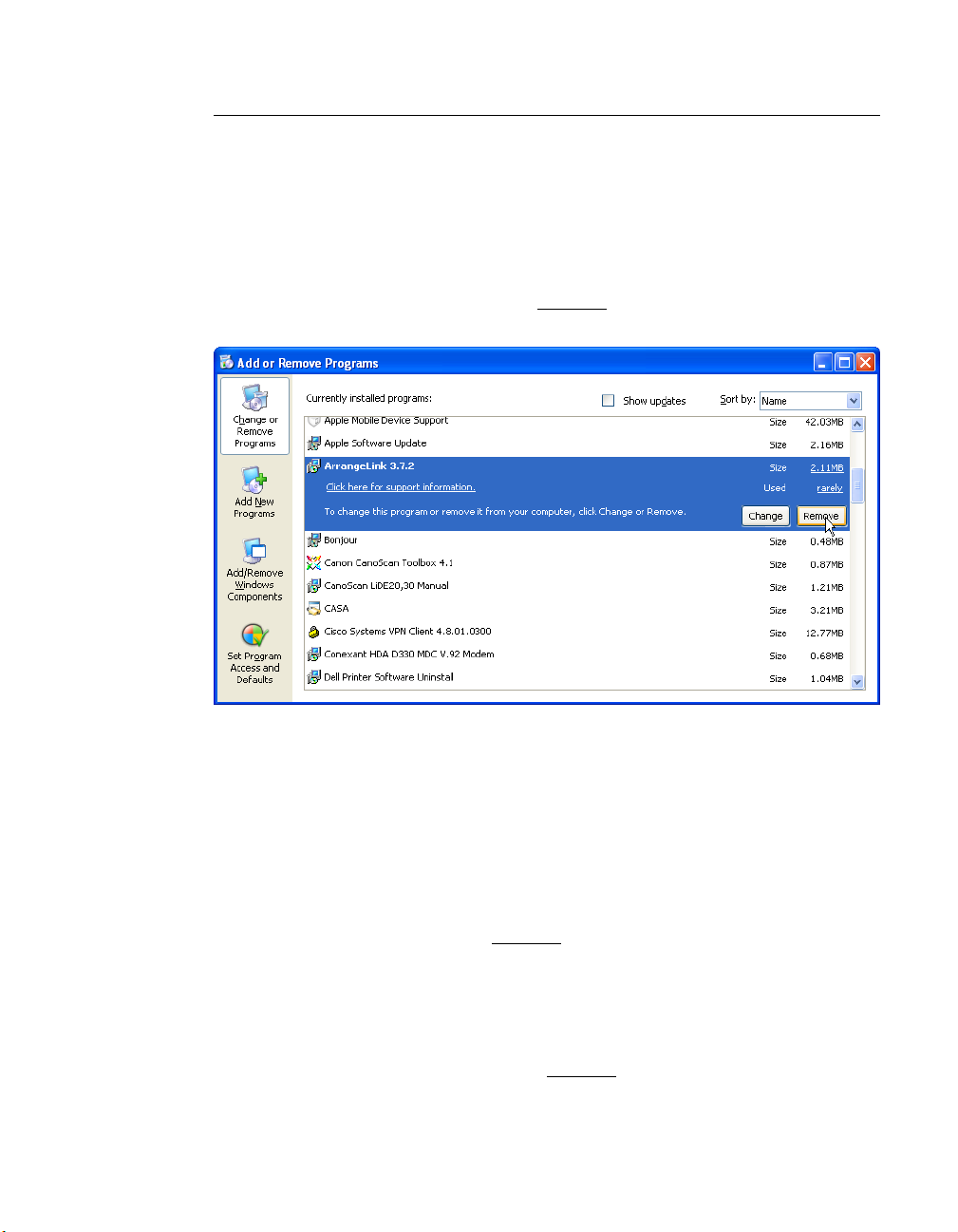
Remove ArrangeLink or VCS
1. From the Add or Remove Programs control panel, select the ArrangeLink
(or VCS) program and click on the Remove
button, as shown in figure 2-6.
Figure 2-6
2. A confirmation dialog window will appear. Click on the Continue button to
remove the program.
Remove ArrangeLink Program
Remove VMS SOAP Server
From the Add or Remove Programs control panel, select the VMS SOAP
Server program and click on the Remove
button.
Remove VMS
From the Add or Remove Programs control panel, select the Vipersat Management System program and click on the Remove
Chapter 2 - Installation 2-7
button.
Page 26

Server Preparation
Install VMS
The VMS Web Services SOAP Server host machine must have a VMS Full
Install performed; this is necessary in order to provide the required support files
for proper operation of the SOAP interface. However, this copy of VMS is not
used to manage the Vipersat network.
NOTE
Note: The version number of the VMS Core software must match the version
number of both the SOAP Server software and the ArrangeLink application software.
A VMS Crypto-Key is not required, and these files are not called upon to
execute the client application.
To perform the VMS Full Install, follow the installation procedure in the section
“VMS Server Installation” in Chapter 2 of the Vipersat Management System
User Guide, then return here to continue with this procedure.
2-8 ArrangeLink User Guide
Page 27
Installation Procedure
Use the following procedure to install the ArrangeLink Web Service on the
SOAP Server.
Note that the installation and configuration must be done using an Administrator login.
Installation Procedure
Caution: This software must be installed on a platform that is running Windows
Server 2003. Installing the SOAP Services on a computer that is not
running Windows Server 2003 will void VMS product support.
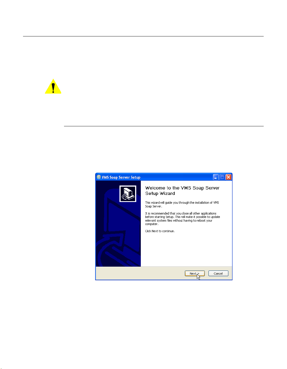
Install SOAP Services
1. Locate the VMS SOAP Setup.exe file on the VMS program distribution CD
and double-click on the file to start the installer.
This will open the VMS SOAP Server Setup Wizard (figure 2-7) that will
install the SOAP services.
Figure 2-7
2. Click the Next button to progress through the Setup process.
3. Specify the Start Menu Folder for locating the program shortcuts. This
folder defaults to the folder that was specified for the VMS installation.
Chapter 2 - Installation 2-9
VMS SOAP Server Setup Wizard
Page 28

Installation Procedure
Figure 2-8
Choose Start Menu Folder
4. As shown in figure 2-9, the Installer will present a dialog requesting the
VMS SOAP Server Configuration parameters.
Figure 2-9
VMS SOAP Server Configuration
• VCS Port
This parameter specifies the TCP port used by the SOAP Server for the
VCS ArrangeLink application. The default port is decimal 8082. Any
2-10 ArrangeLink User Guide
Page 29

Installation Procedure
available port can be specified, provided that the client VCS applications
send their request to this port.
• VNO Port
This parameter specifies the TCP port used by the SOAP Server for the
VNO application. The default port is decimal 8080. Any available port can
be specified provided that the client VNO applications send their request
to this port.
• Basic User Authentication
This check box indicates whether the Basic User Authentication is enabled
or not. If enabled, each client request contains a user name and password
in the HTTP header. The
SoapAdmin.exe utility is used to configure the
user database and privilege levels. This utility is located in the VMSinstalled directory
Program Files\Vipersat\VMS\3.0\bin.
• VMS Server IP
This parameter specifies the IP address(es) of the VMS server(s). In a
standalone VMS configuration, enter the one VMS server IP address. In a
redundant VMS configuration, up to nine addresses can be entered (e.g.,
for all VMS servers in the same redundancy group).
5. Enter the parameters described above, then click on the Install button.
The installation progress will be displayed, ending with the “Installation
Complete” notification.
Figure 2-10
Chapter 2 - Installation 2-11
SOAP Server Installation Complete
Page 30

Installation Procedure
6. Click on the Next button, then Finish to close the wizard.
7. Open the
Services Control Manager and verify that the VMS Web Services
appears in the list of services.
Figure 2-11
Services Control Manager, VMS Web Services
Install ArrangeLink Web Application
The version number of the ArrangeLink client application software must match
the version number of both the VMS Core software and the SOAP Server software.
An Installation Wizard guides the user through the installation process and
prompts for all necessary information to complete the Web application installation.
1. Copy the ArrangeLink_Setup.zip file to the local drive on the server
workstation.
This file is included in the VMS release file set that is available either from
the VMS distribution CD-ROM or as a download from the Comtech EF Data
web site.
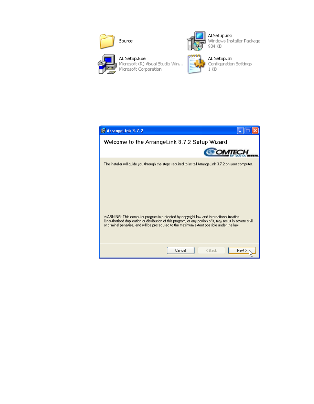
2. Double-click the ArrangeLink_Setup file and extract the program files, as
shown in figure 2-12.
2-12 ArrangeLink User Guide
Page 31
Installation Procedure
Figure 2-12
ArrangeLink Program Files
3. Double-click on the AL Setup.exe file to run the ArrangeLink Setup Wizard.
The Welcome window will appear, as shown in figure 2-13.
Figure 2-13
Welcome, Setup Wizard
4. Click on the Next button to progress to the License Agreement dialog
(figure 2-14).
Carefully read the agreement. To proceed with the installation, click the “I
Agree” radio button, then click on Next.
Chapter 2 - Installation 2-13
Page 32

Installation Procedure
Figure 2-14
License Agreement, Setup Wizard
5. Specify the virtual directory to install the program into, as shown in
figure 2-15. “AL” is used as the default directory on the local C: drive.
Figure 2-15
Select Installation Address, Setup Wizard
2-14 ArrangeLink User Guide
Page 33

Installation Procedure
6. Clicking the Disk Cost... button displays the list of available drives with
their available space, and the space required for the AL program, as shown
in figure 2-16.
Select the desired drive and click the OK button.
Figure 2-16
Select Disk Drive, Setup Wizard
7. Click the Next button to proceed to the Confirm Installation dialog,
figure 2-17.
Figure 2-17
Confirm Installation, Setup Wizard
Chapter 2 - Installation 2-15
Page 34

Installation Procedure
8. Click the Next button to initiate the program installation.
The Wizard will display the progress screen shown in figure 2-18, indicating
software installation on the workstation. When this process is finished, click
the Next button again.
Figure 2-18
Installation Progress, Setup Wizard
9. The Wizard will display the Installation Complete screen shown in
figure 2-19, confirming the successful installation of the ArrangeLink program.
Click the Close button to exit the Setup Wizard.
2-16 ArrangeLink User Guide
Page 35

Installation Procedure
Figure 2-19
Installation Complete, Setup Wizard
This concludes the installation procedure for the VMS Web Services and the
ArrangeLink program. Proceed to the next section for server configuration
instructions.
Chapter 2 - Installation 2-17
Page 36

Server Configuration
After successfully completing the “Installation Procedure” on page 2-9, it is
necessary to perform some configuration steps on the server(s) to assure that the
ArrangeLink program can be accessed via the client PC web browser.
Set Up Log On Account
1. In the Services window, right-click on the VMS Web Services and select
Properties from the drop-down menu.
2. In the Properties dialog, click on the Log On tab, as shown in figure 2-20.
Server Configuration
Figure 2-20
3. Enter an account user name and password that matches the user account that
is running the VMS Server.
This account must be identical to (or be in the same user group as) that used
for running the VMS Server in order for the Web Services to communicate
with the VMS. If these user credentials do not match, an “Access Denied”
error will result when attempting to connect.
4. Click on OK to save this account and close the Properties dialog.
2-18 ArrangeLink User Guide
Account Set Up, VMS Web Services
Page 37

Server Configuration
5. Start the VMS Web Services.
A single beep will indicate that the service started. Verify that the status has
changed to Running.
Set Users Security
This procedure sets the AL Users permissions that allow access to the Web
application.
1. From the Local Disk (C:) on the SOAP Server workstation, locate the AL
directory that holds the ArrangeLink program files. This folder can be found
using the path
C:\inetpub\wwwroot\AL, as shown in figure 2-21.
Figure 2-21
Chapter 2 - Installation 2-19
AL Directory, Properties Command
Page 38

Server Configuration
2. Right-click on the AL folder and select Properties from the drop-down
menu.
The AL Properties dialog window will open (figure 2-22).
Figure 2-22
Security Permissions, AL Properties
3. Open the Security tab and select the Users group for this server. Ensure that
the Allow
permissions are enabled as shown.
4. Click the OK button to save this configuration.
2-20 ArrangeLink User Guide
Page 39

Server Configuration
Configure Firewall
If the Windows Firewall has been enabled, an exception must be added to allow
access to ArrangeLink on the server through port 80 (the default Web server
port) as described in the following procedure:
1. Open the Windows Firewall control panel, and select the Exceptions tab.
2. Click on the Add Port... button to display the Add a Port dialog
(figure 2-23).
Enter the Name and Port number for enabling access to the ArrangeLink web
service application.
Figure 2-23
Add a Port dialog
The name entered in the Name field must be the same name assigned to the
virtual folder (default is AL
) during installation, and the port number entered
in the Port Number field must be the same as the port number (default is 80
assigned during installation.
3. Click the OK button to create the exception in Windows Firewall.
NOTE
Chapter 2 - Installation 2-21
Note: If other firewall software is being used, refer to the firewall software’s
documentation for instructions on allowing access to the ArrangeLink
program.
)
Page 40

Verifying Installation
After completing the installation of the ArrangeLink program and the configuration of the server, verify that the application is running correctly and is
communicating with the VMS by using the following procedure.
Verification can be performed either from a local/remote PC workstation that
has browser software (such as Internet Explorer) and network access, or from
the local server that is hosting the web services.
1. Open the browser window and turn off the Pop-up Blocker function. With
Internet Explorer, for example, this is done using the drop-down Tools menu
as shown in figure 2-24.
Verifying Installation
Figure 2-24
Disable Pop-up Blocker
2. Enter the ArrangeLink target address in the Address field as:
http://<IP_address>/AL
Here, <IP_address> corresponds to the IP address of the hosting server.
When running the program from another workstation, the specific IP address
of the hosting server must be used (figure 2-25). When running the program
directly from the server,
2-22 ArrangeLink User Guide
localhost can be substituted.
Page 41

Verifying Installation
Figure 2-25
Log In dialog
3. ArrangeLink is installed with a default user ID and password which must be
used to log in:
User ID: admin
Password: Comtech
4. After a brief period, the ArrangeLink Introduction screen, shown in
figure 2-26, will be displayed.
Chapter 2 - Installation 2-23
Page 42

Verifying Installation
Figure 2-26
ArrangeLink Introduction Screen
This concludes the ArrangeLink Installation section.
2-24 ArrangeLink User Guide
Page 43

USING ARRANGELINK
General
The Vipersat ArrangeLink Circuit Scheduler is a satellite circuit scheduling
system which works with the Vipersat Management System (VMS) to establish
satellite network circuits automatically based on predefined time and date
settings. ArrangeLink supports both point-to-multipoint (broadcasting) and
point-to-point InBand satellite circuits.
C
HAPTER
ArrangeLink capabilities include:
• Support for InBand point-to-point, point-to-multipoint, and upstream
switch circuits.
• Schedules based on the circuit type, start/end date/time, transmission data
rate, transmitter node and receiver node circuit types.
• Viewing schedules by user-configured filters. Filter parameters include
circuit type, schedule type, start/end date/time, status, and tags. The
contents of a schedule include schedule name, circuit type, transmitter,
receiver, start/end date/time, data rate, and status.
• Operator control of a running event such as immediate termination, or
modification of the end date and time. For a pending scheduled event, the
user can start immediately, modify, or delete the event.
• Viewing a schedule's details of assigned circuit channel, reserved
bandwidth slot, Modulator/Demodulator list, and link quality (E
• Executing a scheduled event based on the detailed requirements for the
event, such as participating nodes, data rates, start date and time, end date
and time, and circuit type. All participating nodes are automatically
Chapter 3 - Using ArrangeLink 3-1
b/No
).
Page 44

General
initiated and satellite links established at the scheduled start time and
maintained for the specified duration.
• Creating and viewing schedules in UTC (Universal Time Coordinates).
Thus, the user always sees event schedules expressed using local date and
time.
3-2 ArrangeLink User Guide
Page 45

Accessing ArrangeLink
ArrangeLink, being a web-based program, can be accessed from any location on
the LAN/WAN network using a web browser, such as Microsoft’s Internet
Explorer.
SOAP Server
When working directly from the hosting server workstation where the ArrangeLink web service is installed, the program is accessed using the URL:
http://localhost/AL
Local/Remote PC
When working from a local or remote client PC workstation, ArrangeLink is
accessed using the URL:
http://<server_IP_address>/AL
Log In
Accessing ArrangeLink
NOTE
Note: ArrangeLink access is password protected. The user must have an
account on the server and enter the exact account name and password
for the server account when logging in to ArrangeLink.
A successful connection to ArrangeLink through the internet browser will result
in the Log In screen appearing (figure 3-1). Log in using the User ID and associated Password that is provided by the system administrator. The default
settings are:
User ID: admin
Password: Comtech
Chapter 3 - Using ArrangeLink 3-3
Page 46

Accessing ArrangeLink
Figure 3-1
ArrangeLink Log In Prompt
Note that, should there be a problem with the SOAP Service or an incorrect
URL address for either the VCS or VNO, the log in attempt will fail and an
error message will be displayed, as shown in figure 3-2.
Figure 3-2
Log In Failure
Should a log in attempt fail, contact the network system administrator for assistance.
3-4 ArrangeLink User Guide
Page 47
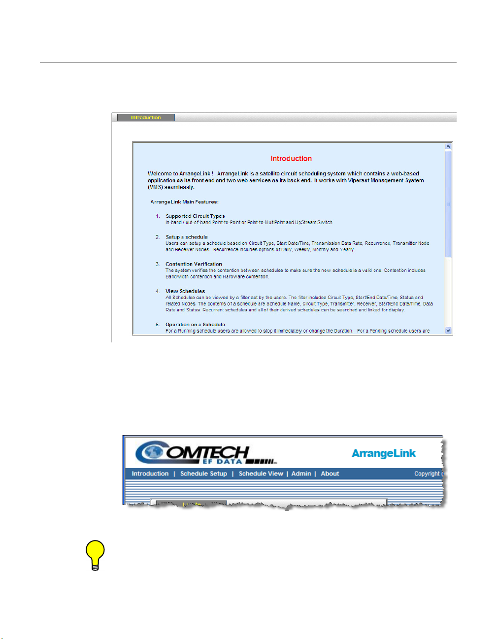
Introduction
When a client logs in to the ArrangeLink server, the Introduction screen, shown
in figure 3-3, is displayed.
Introduction
Figure 3-3
Introduction Screen
After reviewing the main program features, use the command bar, shown in
figure 3-4, to move to the next screen. Clicking on Schedule Setup, the next
item on the command bar, for example, will bring up the Schedule Setup screen
shown in figure 3-7.
Figure 3-4
Tip: Before attempting to set up a schedule, select the Schedule View option
to determine what equipment, bandwidth, and times are available before
attempting to establish a new schedule.
Chapter 3 - Using ArrangeLink 3-5
Command Bar
Page 48

Introduction
This will prevent creating a new schedule that is in conflict with an existing
schedule.
NOTE
Note: If there is a VMS managed event that is ongoing at the time of a sched-
uled event, assigned priorities will determine whether or not the scheduled event will supersede the ongoing event and take over the SCPC
circuit.
See the section “Advanced Switching” on page 3-22 regarding the
setting of the Priority level for a scheduled event.
3-6 ArrangeLink User Guide
Page 49

Schedule Setup
Before attempting to schedule events on a circuit, a valid image of the VMS
database must be reflected in the ArrangeLink database.
To download a current image of the VMS database into the ArrangeLink database, click on Admin in the command bar. Then click on the Synchronize Now
button.
Schedule Setup
Figure 3-5
Synchronization with VMS
Following the synchronization command, a confirmation pop-up window will
appear indicating that the process was successful.
Figure 3-6
Chapter 3 - Using ArrangeLink 3-7
Successful Synchronization Message
Page 50

Schedule Setup
NOTE
Note: If ArrangeLink is unable to find a valid VMS database on the server while
attempting the synchronization, an error message will be displayed.
Schedule Setup Sub-Screens
Click on Schedule Setup in the command bar.
The Schedule Setup screen has four tabbed sub-screens: Generic Options,
Scheduling Options, Circuit Specific Options, and Advanced Switching, as
shown below in figure 3-7.
Figure 3-7
Schedule Setup, Generic Options Tab
Generic Options
The first sub-screen, Generic Options, shown in figure 3-7, is used for giving a
Name to the scheduled event, selecting the profile for a Time Zone reference,
setting an Execution Delay interval, and creating optional Schedule Tags to be
associated with this event.
Configure the parameters for this sub-screen as described below.
3-8 ArrangeLink User Guide
Page 51

Schedule Setup
Schedule Name
Enter a name for the event that is being scheduled in the Schedule Name box.
The name entered is used to identify this event. This field entry defaults to a
name consisting of the current date and time.
Time Zone Profile
The time reference for this event can be specified from the pull-down menu as
one of the following:
• 1 Pacific Time
• 2 Eastern Time
• 3 Greenwich Time
First Occurrence
Select either Yes or No from the pull-down menu, depending on whether or not
this is a first occurrence for a recurring event.
Exclusion Profile
Although this feature appears as a settable option, it is not supported in v3.7.2 of
the VMS.
Max. Execution Delay
The time interval specified for the Maximum Execution Delay parameter
ensures that an event will still be executed, even if a delay should occur beyond
the scheduled start time—caused by the VMS being temporarily unavailable,
for example. However, if the delay exceeds this interval, the event will not be
executed.
The default value for this parameter is 600 seconds (10 minutes). This entry
should be set to an interval that is less than the specified duration of the event.
When the scheduled start time for the event occurs, the VMS will attempt to set
up the defined circuit and will continue to do so for the delay time interval until
either a connection is made or the event’s time allocation is exceeded
Schedule Tag
In addition to the Schedule Name, one or more Schedule Tags can be associated with an event, or a group of common events. This provides another means
for filtering events with the search function when viewing scheduled events (see
the section “Schedules” on page 3-28).
Enter any desired combination of characters to insert a Tag for the event.
Chapter 3 - Using ArrangeLink 3-9
Page 52

Schedule Setup
After completing the configuration of the parameters in the Generic Options
screen, click the Continue button to proceed to the Scheduling Options tab.
Scheduling Options
The second Schedule Setup sub-screen, Scheduling Options, displays the
configuration parameters shown in figure 3-8. From this screen, parameter
settings are made for the Schedule Type, Start and End Dates, Start Time and
Duration, and any Recurrence of the event.
Figure 3-8
Schedule Setup, Scheduling Options Tab
Schedule Type
The Schedule Type can be specified for One Time Only, Daily, Weekly, or
Monthly. The screen appearance for the Recurrence field will vary for each
type, as described below.
Valid Date Range
This section of the screen allows the Start Date and End Date of the event to
be specified. Clicking on the Start/End Date box activates the calendar, as
3-10 ArrangeLink User Guide
Page 53

Schedule Setup
shown in figure 3-9. Use the calendar to select the desired date for the event,
which will then appear in the box.
Note that only the Start Date field appears when the schedule type is set to One
Time Only.
Figure 3-9
Calendar Selection, Start Date
Each Occurrence
In this section of the screen, the Start Time and Duration of the event are specified. From the drop-down list boxes shown in figure 3-10, select the Start Time
hour, minute, and AM or PM for the scheduled event.
Chapter 3 - Using ArrangeLink 3-11
Page 54

Schedule Setup
NOTE
Figure 3-10
Time Selection, Each Occurrence
Select the Duration of the event in day(s), hour(s), and minute(s).
Note: If a required parameter is not specified, or is of an inappropriate range,
an alert message for that parameter is displayed when the Continue
button is clicked. The user must make the required corrections prior to
proceeding to the next screen.
An example of an incorrect Duration specification is shown in figure 3-11.
Figure 3-11
Duration Parameter, Alert Message
Recurrence
The Recurrence parameter settings appear when the Schedule Type is Daily,
Weekly, or Monthly. There are no recurrence settings for One Time Only.
3-12 ArrangeLink User Guide
Page 55

Schedule Setup
Daily
When Daily is chosen as the Schedule Type, the screen appearance for the
Recurrence section changes to reflect this type, as shown in figure 3-12.
Figure 3-12
Daily Schedule Type
Select either Every Day(s), Every Weekday, or Every Weekend for the Recurrence. Note that the Duration of the event must be less than the Recurrence
period.
Weekly
When Weekly is chosen as the Schedule Type, the screen appearance for the
Recurrence section changes to reflect this type, as shown in figure 3-13.
Figure 3-13
Weely Schedule Type
Specify the number of Weeks and the Day of the week that this event will be
recurring.
Monthly
When Monthly is chosen as the Schedule Type, the screen appearance for the
Recurrence section changes to reflect this type, as shown in figure 3-14.
Chapter 3 - Using ArrangeLink 3-13
Page 56

Schedule Setup
Figure 3-14
Monthly Schedule Type
Specify the Day of the month by selecting either the numeric date or the weekday and its week in the month, then select the Month that this event will be
recurring.
When configuration of the Scheduling Options is completed, click on the
Continue button to proceed to the Circuit Specific Options tab.
Circuit Specific Options
The third Schedule Setup sub-screen, Circuit Specific Options, presents the
equipment and circuit type to be used by the scheduled event. Clicking the
Circuit Specific Options tab displays the information shown in figure 3-15.
From this screen the user can:
• Choose the circuit type to be used for the scheduled event.
• Select the devices to be used in the circuit from the tree display of devices
available on the network.
3-14 ArrangeLink User Guide
Page 57

Schedule Setup
NOTE
Figure 3-15
Schedule Setup, Circuit Specific Options Tab
The device selection boxes will change to accommodate the Circuit Type
selected using the InBand, Out-of-Band or UpStream Switch radio buttons
shown in figure 3-15.
Circuit Type
The type of circuit selected for an event will be chosen by the traffic type. The
following sections contain brief descriptions of each of the available circuit
types. The schedule information, once entered into ArrangeLink, is stored in a
data base on the hosting web server.
The current satellite network configuration is retrieved from the VMS and is
used whenever hardware and bandwidth resources are allocated for a scheduled
event.
ArrangeLink allows scheduling events using InBand circuits for:
• Point-to-Point
• Point-to-MultiPoint
• UpStream Switch
Note: Although non-Vipersat modems can be monitored by the VMS (via the
SNMP Modem Manager), Out-of-Band switching
supported in version 3.7.2. Do not attempt to select Circuit Types for
either Point-to-Point Out-of-Band or Point-to-Multipoint Out-of-Band.
of these modems is not
Chapter 3 - Using ArrangeLink 3-15
Page 58

Schedule Setup
InBand Circuit
An InBand circuit refers to a circuit which has its control channel within the
same band as the communication channels. In figure 3-16, SCPC and STDMA
In-Band circuits are shown for a Vipersat network using CDM-570L modem/
routers.
Figure 3-16
InBand Circuit diagram
This type of connection applies to circuits which utilize Comtech EF Data
modem devices containing an integral IP router (Viperized).
Out-of-Band Circuit
An Out-of-Band circuit applies when a configuration similar to the one shown
in figure 3-17 is used to establish a high-speed data link between non-Vipersat
units such as the CDM-600L and its companion CiM-25 IP module. The
management and control commands from the VMS are transmitted and received
InBand by the CDM-570L circuit. These commands are then routed by the
CDM-570L over Ethernet to the CDM-600L modem.
Since the management and control signals are handled by the CDM-570L
within its allocated bandwidth and do not occupy any of the CDM-600L’s bandwidth, these command circuits are considered Out-of-Band with respect to the
CDM-600L circuit.
3-16 ArrangeLink User Guide
Page 59

Schedule Setup
NOTE
Figure 3-17
Out-of-Band Circuit diagram
Use one of the following procedures—Point-to-Point InBand, Point-to-MultiPoint InBand, or Upstream Switch—to select the circuit options to be used for
an event that is being scheduled.
Note: The circuit type that can be used for a scheduled event may be limited by
the available satellite network hardware and bandwidth.
Tip: Click on the Uncheck All button located below the network device list to
remove checks from all boxes in the dialog.
Point-to-Point Out-of-Band
Although this Circuit Type appears as a selection option, it is not supported in
v3.7.2 of the VMS.
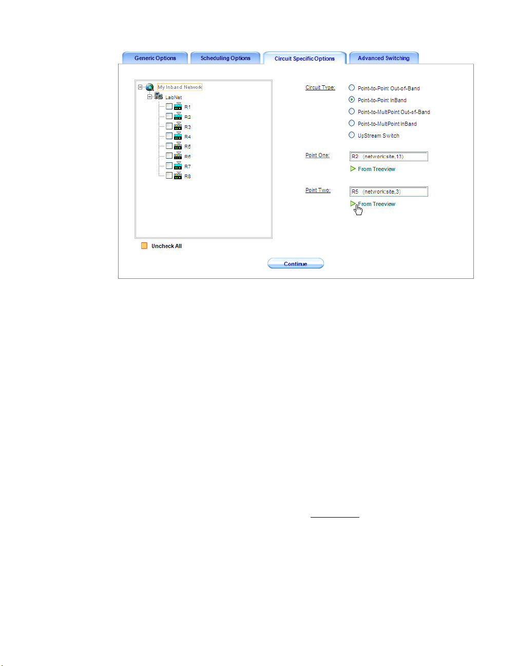
Point-to-Point InBand
In figure 3-18, the Point-to-Point InBand circuit type has been selected using
the Circuit Type radio button. Use the following procedure to select the equipment to be used during the scheduled event.
Chapter 3 - Using ArrangeLink 3-17
Page 60

Schedule Setup
NOTE
Note: Notice in figure 3-18 that all of the Out-of-Band devices have been
suppressed and only InBand devices are shown as available for this
scheduled event.
Figure 3-18
Point-to-Point InBand Circuit, Point One
To set up the scheduled event, select the Point One and Point Two sites as
follows:
1. Select the Point One device to be used from the network tree by clicking in
the box next to the Remote site icon, as shown in the figure.
2. Click the From Treeview item under the Point One box. The selected site
will automatically be entered in the Point One box, as shown in figure 3-19.
3. Select Point Two by selecting the second Remote site from the network tree.
4. Click the From Treeview under the Point Two box to automatically enter
the second site into the Point Two box, as shown in figure 3-19.
3-18 ArrangeLink User Guide
Page 61
Schedule Setup
Figure 3-19
Point-to-Point InBand Circuit, Point Two
When configuration of the Circuit Specific Options is completed, click on the
Continue button to proceed to the Advanced Switching tab.
Point-to-MultiPoint Out-of-Band
Although this Circuit Type appears as a selection, it is not supported in v3.7.2 of
the VMS.
Point-to-MultiPoint InBand
In figure 3-20, the Point-to-Multipoint InBand circuit type has been selected
using the Circuit Type radio button. Use the following procedure to select the
equipment to be used for this circuit during the scheduled event.
1. Select the Remote site to be used as the transmitter for the scheduled event
from the network tree view, as shown in the figure.
Chapter 3 - Using ArrangeLink 3-19
Page 62

Schedule Setup
Figure 3-20
Point-to-Multipoint InBand Transmitter
2. Click the From Treeview button to transfer the selected transmitter to the
Transmitter box.
The identification parameters are displayed in the Transmitter box and
stored in the database for this event.
3. Select the sites to be used as the receivers
during the scheduled event from
the network tree.
4. Transfer the selected receivers to the Receiver box by clicking the From
Treeview button (figure 3-21).
Additional receiver sites can be selected and transferred at any time.
5. If a transferred receiver site is not to be included in the scheduled event, that
receiver can be removed from the list by selecting it in the Receiver box,
then clicking the Remove button (figure 3-22).
3-20 ArrangeLink User Guide
Page 63

Schedule Setup
Figure 3-21
Figure 3-22
Point-to-Mulitpoint InBand Receivers
Remove Receiver from List
When configuration of the Circuit Specific Options is completed, click on the
Continue button to proceed to the Advanced Switching tab.
Upstream Switch
Because an Upstream Switch is always between a Remote and the Hub, only a
single Point has to be specified—the Remote site. An Upstream Switch event
can be scheduled using the following procedure:
Chapter 3 - Using ArrangeLink 3-21
Page 64

Schedule Setup
Select the Upstream Switch Circuit Type radio button, as shown in
1.
figure 3-23.
Figure 3-23
Upstream Switch, Remote Selection
2. Select the Remote site to be switched for this event from the network tree
view.
3. Click the From Treeview button to transfer the selected site to the Remote
box.
4. The identification parameters are displayed in the Remote box and stored in
the database for this event.
When configuration of the Circuit Specific Options is completed, click on the
Continue button to proceed to the Advanced Switching tab.
Advanced Switching
The fourth Schedule Setup sub-screen, Advanced Switching, presents the carrier
channel Mod/Code settings to be used by the scheduled event. Clicking the
3-22 ArrangeLink User Guide
Page 65

Schedule Setup
Advanced Switching tab displays the information shown in figure 3-24. From
this screen the user can:
• Choose the combination of Modulation Type, and FEC Code Rate and
Type to be used for the scheduled event.
• Specify the channel Data Rate for the event.
• Set a Priority level for the event.
Figure 3-24
1. Set the required Mod/Code parameters using the pull-down menus that
Schedule Setup, Advanced Switching Tab
appear under each table entry under the Value column.
The defaults for these settings are displayed in the second table column.
2. Enter the required channel Data Rate (kbps). The default setting for this
parameter is 256.
3. Set the Priority level for this event. The default setting is 0 (this equates to
no priority).
Note that a lower number corresponds to a higher priority level. Thus,
priority 1 is the highest level. The lowest level is 2,147,483,646.
In a VMS managed network, resource allocation preference is based on the
highest priority among contending sites, application policies, and/or
scheduled events. If there is a VMS managed event that is ongoing at the
Chapter 3 - Using ArrangeLink 3-23
Page 66

Schedule Setup
time of a scheduled event, assigned priorities will determine whether or not
the scheduled event will supersede the ongoing event and take over the
SCPC circuit.
Click the Add Schedule button to complete the scheduling of this event and add
the event to the ArrangeLink database.
3-24 ArrangeLink User Guide
Page 67

Schedule View
Clicking Schedule View from the command bar (see figure 3-4) displays the
Schedule View screen shown in figure 3-25. This screen is used to view pending, starting, running, as well as completed, failed, and expired events, and is
comprised of three tabbed sub-screens:
• Schedule Instances – displays all event category types that match the
view filter inputs, with a listing of all instances of recurring events.
• Schedules – displays all event category types that match the view filter
inputs, with a single listing of each recurring event.
• Details – displays additional information for an event that has been
selected in either the Schedule Instances tab or the Schedules tab.
Schedule View
Figure 3-25
In order to have the most current information displayed, it may be necessary to
perform a VMS Synchronization. Click on the Admin tab in the command bar,
then from the VMS tab, click on the Synchronize Now button.
Clicking the Refresh icon, located at the top of the schedule list table, updates all
displayed information for the schedules in this view.
The Expand icon (arrow pointing to the left) is used to remove the filter selec-
tion panel and expand the report display to fill the screen, providing a larger
Chapter 3 - Using ArrangeLink 3-25
Schedule View, Schedule Instances Tab
Page 68

Schedule View
area to view the schedule list table. This minimizes horizontal scrolling. When
the table view is in the expanded mode, this icon changes to a Contract function (arrow pointing to the right).
Use the following procedures to filter, view, and act on event schedules stored
in the ArrangeLink database.
Schedule Instances
The first Schedule View sub-screen, Schedule Instances, provides a means of
searching for and viewing defined instances of scheduled events. The View
filter panel appears on the left of the screen and a panel to the right of the filter
displays the event listing table. The View filter is a flexible tool that controls
what listings appear for past, current, and pending scheduled events.
The events to be viewed can be as specific or as general as desired based upon
the combination of parameters that are chosen. The particular selection of
circuit type, status, start date and time, and end date and time determines what
events will appear in the table listing. In this view screen, all occurrences for a
recurring event during the defined date/time period are displayed as separate
listings.
Figure 3-26
3-26 ArrangeLink User Guide
Schedule Listing Table
Page 69

Schedule View
In the schedule listing example shown in figure 3-26, all events for the next
three week period are displayed by setting the filter parameters as follows:
• Circuit and Status are set to Any.
• The Start Date is set to 11/17/2009 (defaults to the current date), and the
Start Time is set to 12 AM (also the default).
• The End Date is set for three weeks later (12/8/2009), and an End Time
of 1 AM has been chosen.
Alternative filter choices for Circuit and Status are:
• Circuit – P2P InBand, P2M InBand, Upstream
• Status – Pending, Running, Completed, Failed, Expired
After setting the desired filter parameters, clicking the View button displays all
of the scheduled events in the right panel which meet the conditions set in the
filter.
Note that the events are presented with their date and time based on the current
setting of the Time Zone field (Pacific, Eastern, or Greenwich) located in the
upper right of the screen.
Each of the displayed events can be acted upon by first selecting the event and
then clicking on one of the action command buttons that appear below the
schedule listing table:
• Start – starts the event immediately, overriding the scheduled start time.
• Stop – stops a running event immediately, overriding the scheduled stop
time.
• Modify – allows the parameters of the scheduled event to be edited. Only
applies to Pending events.
• Delete – removes the event from the ArrangeLink and VMS database.
Past schedules
ArrangeLink stores past (Completed/Failed/Expired) scheduled events in its
database so that historical records can be retrieved whenever required.
Use the same process as described in the example above to select a circuit and
status type, then specify the past time period with the start and stop date and
time settings to retrieve the desired past scheduled events. All past events for the
specified period will be displayed by selecting the Any
displays will result by setting the Status to Completed
Additional information for an event listing can be displayed by first selecting
the event in the table and then opening the Details tab (see the section “Selected
Schedule Details” on page 3-30 for more information).
Chapter 3 - Using ArrangeLink 3-27
Status. More selective
, Failed, or Expired.
Page 70

Schedule View
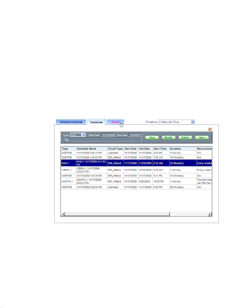
Schedules
The second Schedule View sub-screen, Schedules, displays events based on the
specified Schedule Type, the Start Date, and the End Date, as shown in
figure 3-27. The View filter panel and action command buttons appear at the top
of the screen, and a large panel below the filter displays the event listing table.
Similar to the Schedule Instances screen, there are filter controls for displaying
past, current, and pending scheduled events. However, this screen has a different set of View filter parameters and action commands, and displays only one
listing for a recurring event, even if multiple occurrences of that event fall
within the defined date period.
Figure 3-27
Schedule View, Schedules Tab
In the schedule listing example shown in figure 3-27, all events that are scheduled to occur over a six month period are displayed by setting the Type to Any
together with a Start Date of November
and an End Date of May.
Alternative settings for Type are: Onetime, Daily, Weekly, and Monthly.
Additionally, there is a Tag filter parameter that is used to display only those
events that have a matching schedule tag associated with them (figure 3-28).
These tags are assigned to an event in the Generic Options screen when
performing a Schedule Setup.
3-28 ArrangeLink User Guide
Page 71

Schedule View
Figure 3-28
Schedules Tag Filter Parameter
After making the desired filter settings, clicking the View button displays all of
the scheduled events that meet this criteria. Note that the events are presented
with their date and time based on the current setting of the Time Zone field
(Pacific, Eastern, or Greenwich) located at the top right of the screen.
Each of the displayed events can be acted upon by first selecting the event and
then clicking on one of the action command buttons that appear in the upper
right panel above the schedule listing table:
• Stop – stops a running event immediately, overriding the scheduled stop
time.
• Modify – allows the parameters of the scheduled event to be edited. Only
applies to Pending events.
• Delete – removes the event from the ArrangeLink and VMS database.
Additional information for an event listing can be displayed by first selecting
the event in the table and then opening the Details tab (described in the following section).
Chapter 3 - Using ArrangeLink 3-29
Page 72

Schedule View
Selected Schedule Details
The third Schedule View sub-screen, Details, works in conjuction with both the
Schedule Instances screen and the Schedules screen. Selecting a scheduled
event from one of these two screens and then opening the Details tab will
provide additional information pertaining to that specific event.
Figure 3-29
Schedule View, Details for Schedule Instance
Schedule Instances Details
The details for the Onetime Upstream Switch event that is selected in the Schedule Instances screen example (figure 3-26) is shown in figure 3-29, above.
This screen has an upper panel that presents the following details:
• Schedule Name – the name assigned to this schedule.
• Circuit Type – the type of circuit for this schedule.
• Data Rate/Priority – the specified data rate (kbps) and priority level.
• Start Date/Time – the date and time for this event to start.
• End Date/Time – the date and time for this event to end.
• Status – pending, starting, running, completed, failed, or expired.
3-30 ArrangeLink User Guide
Page 73

Schedule View
Mobile – indicates if this schedule is for a mobile application.
•
• Transmitter – identifies the Remote site ID of the transmitter for this
event.
• Receiver – identifies the Remote site ID(s) of the receiver(s) for this
event.
Resource allocation details for a Running
event are presented in the lower panel.
• For the Transmitter (top row of the table):
• Channel – the assigned channel for transmitting.
• Frequency (MHz) – the assigned transmit frequency.
• Bandwidth (kHz) – the allocated bandwidth for transmitting.
• Device type – the assigned transmit modulator.
• Device Name – the name of the modulator.
• For the Receiver(s) (lower row(s) of the table):
• Device type – the assigned receive demodulator(s).
• Device Name – the name(s) of the demodulator(s).
• Power (dBm) – the received power level.
• E
(dB) – the received signal quality level.
b/No
Schedules Details
In comparison, the details for the Daily Point-to-Multipoint event that is
selected in the Schedules screen example (figure 3-27) is shown in figure 3-30,
below.
The upper panel of this screen presents the following details:
• Schedule Name – the name assigned to this schedule.
• Schedule Type – the type of event for this schedule.
• Circuit/Rate/Priority – the specified circuit type, data rate (kbps), and
priority level.
• Date Range – the start date and end date for this event or set of events.
• Max. ExecDelay – the time interval specified for the Maximum
Execution Delay parameter.
• Recurrence – the recurrence interval established for this schedule type.
Chapter 3 - Using ArrangeLink 3-31
Page 74

Schedule View
Per Occurrence – the date of the first occurrence and the time duration
•
for each occurrence.
• Transmitter – identifies the Remote site ID of the transmitter for this
event.
• Receiver – identifies the Remote site ID(s) of the receiver(s) for this
event.
Figure 3-30
Schedule View, Details for Schedule
The details for each occurrence of a Recurring event are presented in the lower
panel.
• Start Date / Time
• End Date / Time
• Status – pending, starting, running, completed, failed, or expired.
3-32 ArrangeLink User Guide
Page 75

Admin
Admin
The Admin screen is used to synchronize ArrangeLink with the VMS. To download a current image of the VMS database into the ArrangeLink database, click
on Admin in the command bar to open the VMS tab (figure 3-31). Click on the
Synchronize Now button.
Figure 3-31
Admin Screen, VMS Tab
Following the synchronization command, a confirmation pop-up window will
appear indicating that the process was successful.
Figure 3-32
NOTE
Chapter 3 - Using ArrangeLink 3-33
Note: If ArrangeLink is unable to find a valid VMS database on the server while
attempting the synchronization, an error message will be displayed.
Successful Synch with VMS
Page 76

About
About
The About command is used to display the ArrangeLink program information,
including version and copyright. Click on About in the command bar to open
the dialog window shown in figure 3-33.
NOTE
Figure 3-33
Note: In order for this dialog to be displayed, the browser Pop-ups feature must
be set to “allowed”.
About ArrangeLink dialog
3-34 ArrangeLink User Guide
Page 77

GLOSSARY
ACK A signal used in computing and other fields to indicate acknowledgement, such
as a packet message used in TCP to acknowledge the receipt of a packet.
ARP Address Resolution Protocol – A protocol for a LAN device to determine the
MAC address of a locally connected device given its IP address. See also MAC.
A
A
PPENDIX
ASR Automatic Switch Request – A switch request message generated by older
Vipersat modems (e.g., CDM-570/L) that is sent to the VMS to establish a new
satellite link or adjust bandwidth between source and destination IP addresses.
B
Base
Modem
BER Bit Error Rate (sometimes Ratio) – A measure of the number of data bits
BPS Bits Per Second – A measure of transmission speed. See also Kb/s & Mb/s.
Appendix A - Glossary A-1
The main component in a satellite communications modem that consistes of a
circuit board with the modem hardware and firmware and the associated interfaces.
received incorrectly compared to the total number of bits transmitted.
Page 78

BPSK Binary Phase-Shift Keying – A digital modulation technique in which the
carrier is phase shifted +/-180 degrees (two phases). The most robust of all
PSKs, but unsuitable for high data-rate applications when bandwidth is limited
due to encoding just one bit per symbol.
BUC Block Up Converter – An upconverter so called because it converts a whole
band or “block” of frequencies to a higher band. The IF is converted to final
transmit frequency for satellite communications. The BUC is part of the satellite
ODU/transceiver.
C
C-Band A frequency band commonly used for satellite communications (and sometimes
terrestrial microwave). For terrestrial earth stations, the receive frequency band
is 3.7–4.2 GHz and the transmit band is 5.925–6.425 GHz. See also Ku-band.
CDD Comtech Data Demodulator
CDM Comtech Data Modem
CIR Committed Information Rate – The guaranteed minimum bandwidth assigned
to a remote terminal.
CLI Command Line Interface – A mechanism for interacting with a computer oper-
ating system or software by typing commands to perform specific tasks.
Codecast A network coding based ad hoc multicast protocol well-suited for multimedia
applications with low-loss, low-latency constraints. Because data is streamed
with no verification, high delivery ratios are obtained with very low overhead.
CRC Cyclic Redundancy Check – A method of applying a checksum to a block of
data to determine if any errors occurred during transmission over communications links.
CXR Carrier – A radio frequency transmission linking points and over which infor-
mation may be carried.
D
DAMA Demand Assigned Multiple Access – A process whereby communications links
are only activated when there is an actual demand.
dBm Decibel referenced to 1 milliwatt.
A-2 ArrangeLink User Guide
Page 79

DES Data Encryption Standard – A federal standard method for encrypting informa-
tion for secure transmission. The Vipersat system offers 3xDES (Triple DES)
for encrypting traffic.
DHCP Dynamic Host Configuration Protocol – An Internet protocol for automating
the configuration of computers that use TCP/IP.
DLL Dynamic Link Library – The implementation of the shared library concept in
the Microsoft Windows system.
DPC Dynamic Power Control
DSCP Differentiated Services Code Point – The 6-bit field in an IP packet header that
is used for packet classification purposes and is the portion of ToS that is
detected by Vipersat modems.
DVB Digital Video Broadcast
DVP Digital Voice Processor – Used in packet voice applications.
E
Eb/NoEb/No is the ratio of Eb (energy per bit) and No (noise power density per Hz).
The bit error rate (BER) for digital data is a decreasing function of this ratio. E
is the energy of an information bit measured in Joules or, equivalently, in Watts
per Hertz.
b
F
FAST Code Fully Accessible System Topology Code – Designation for feature code used
by Comtech EF Data for their satellite modems. The FAST method makes it
easy to quickly upgrade the feature options of a modem while it is running live
in the network, either on site or remotely.
FEC Forward Error Correction – A process whereby data being transmitted over a
communications link can have error correction bits added which may be used at
the receiving end to determine/correct any transmission errors which may occur.
Flash Non-volatile computer memory that can be electrically erased and repro-
grammed.
Forward
Path
Appendix A - Glossary A-3
Transmission path from the Hub site to a Remote site.
Page 80

FTP File Transfer Protocol – An application for transferring computer files over the
Internet. See also TFTP.
G
G.729 ITU standard for LD-CELP (Low Delay – Code Excited Linear Prediction)
voice encoding at 8 kb/s.
GIR Guaranteed Information Rate
Group ID A number assigned to equipment which defines it as a member of a group when
addressed by the VMS burst controller.
GUI Graphical User Interface – A form of graphical shell or user interface to a
computer operating system or software application.
H
H.323 A protocol standard for multimedia communications designed to support real-
time transfer of audio (such as voice over IP) and video data over packet
networks. Quality of Service is a key feature of H.323. An alternative to SIP.
HDLC High Level Data Link Control – A standard defining how data may be transmit-
ted down a synchronous serial link.
HPA High Power Amplifier – The amplifier used in satellite communications to raise
the transmit signal to the correct power level prior to transmission to satellite.
HTTP Hyper Text Transfer Protocol – The Internet standard for World Wide Web
(WWW) operation.
Hub The central site of a network which links to a number of satellite earth sites
(remotes).
I
ICMP Internet Control Message Protocol
IDU Indoor Unit – In a VSAT system, the satellite modem is referred to as the IDU.
A-4 ArrangeLink User Guide
Page 81

IF Intermediate Frequency – In satellite systems, IF frequencies are usually
centered around 70 or 140 MHz (video/TV), or 1200 MHz (L-band).
IFL Intra-Facility Link – The coaxial cabling used to connect the satellite ODU to
the IDU. Carries the inbound and the outbound signals, and the 24 VDC for the
LNB.
Image A binary firmware file that provides the operational code for the processor(s) in
a network unit.
IP Internet Protocol – A format for data packets used on networks accessing the
Internet.
ISP Internet Service Provider – A company providing Internet access.
ITU International Telecommunications Union
K
Kb/s Kilo bits per second – 1000 bits/second. A measure of transmission speed. See
also bps & Mb/s.
Ku-Band A frequency band used for satellite communications. For terrestrial earth
stations the receive frequency band is in the range 10.95–12.75 GHz and the
transmit frequency band is 13.75–14.5 GHz. See also C-band.
L
L-Band A frequency band commonly used as an IF for satellite systems using block up/
down conversion. Typically 950–1450 MHz Rx, 1250–1750 MHz Tx.
LAN Local Area Network
LLA Low Latency Application
LNA Low Noise Amplifier – An amplifier with very low noise temperature used as
the first amplifier in the receive chain of a satellite system.
LNB Low Noise Block – A downconvertor so called because it converts a whole
band or “block” of frequencies to a lower band. The LNB (similar to an LNA) is
part of the satellite ODU/transceiver.
LNC Low Noise Converter – A combined low noise amplifier and block down
converter, typically with an L-band IF.
Appendix A - Glossary A-5
Page 82

LO Local Oscillator – Component used in upconverters, downconverters, and tran-
sponders for frequency translation (heterodyne) of the carrier signal.
M
M&C Monitor & Control
MAC Media Access Control – A protocol controlling access to the physical layer of
an Ethernet network.
Mb/s Mega Bits per Second – 1 Million bits/second. A measure of transmission
speed. See also bps & kb/s.
Modem Modulator and Demodulator units combined.
Multicast Transmitting a single message simultaneously to multiple destinations (group)
on the IP network.
Multi-
command
A command that allows multiple input choices in a single command execution..
N
NAT Network Address Translation – An Internet standard that enables a LAN to use
one set of IP addresses for internal (private) traffic and a second set of addresses
for external (public) traffic.
NIC Network Interface Controller – The network interface for a PC/workstation that
provides Ethernet connectivity. Depending on the computer, the NIC can either
be built into the motherboard, or be an expansion card. Some computers (e.g.,
servers) have multiple NICs, each identified by a unique IP address.
NMS Network Management System
NOC Network Operation Center – Has access to any earth station installed using the
VIPERSAT Management System (VMS). A NOC can remotely interrogate,
control, and log network activities.
NP Network Processor
A-6 ArrangeLink User Guide
Page 83

O
ODU Outdoor Unit – In a VSAT system, the RF components (transceiver) are usually
installed outdoors on the antenna structure itself and are thus referred to as an
ODU. The ODU typically includes the BUC and LNB, and is connected to the
IDU/modem by the IFL cabling.
P
PLDM Path Loss Data Message – A packet message that is sent by older Vipersat
modems (e.g., CDM-570/L) to the VMS every sixty seconds, providing status
update and operating parameter information.
PSK Phase-Shift Keying – A digital modulation scheme that conveys data by chang-
ing the phase of a base reference signal, the carrier wave. Different PSKs are
used, depending on the data rate required. Examples are binary phase-shift
keying (BPSK or 2-PSK) which uses two phases, and quadrature phase-shift
keying (QPSK) which uses four phases.
PSTN Public Switched Telephone Network – The world’s public circuit-switched
telephone network, digital and analog, and includes mobile as well as land-line
voice and data communications.
Q
QAM Quadrature Amplitude Modulation – A digital modulation technique in which
the amplitude of two carrier waves is changed to represent the data signal. These
two waves are 90 degrees out of phase with each other.
QoS Quality of Service
QPSK Quadrature Phase-Shift Keying – A digital modulation technique in which the
carrier is phase shifted +/- 90 or +/-180 degrees. With four phases, QPSK can
encode two bits per symbol—twice the rate of BPSK. However, it also uses
twice the power. Also known as 4-PSK or 4-QAM.
Appendix A - Glossary A-7
Page 84

R
Remote Satellite earth site that links to a central network site (Hub).
Return Path Transmission path from a Remote site to the Hub site.
RF Radio Frequency – A generic term for signals at frequencies above those used
for baseband or IF.
RFC Request For Comment – The official publication channel for Internet standards
(such as communication protocols) issued by the Internet Engineering Task
Force (IETF).
RIP Routing Information Protocol
ROSS Roaming Oceanic Satellite Server
RS-232 A common electrical/physical standard issued by the IEEE used for point to
point serial communications up to approximately 115 kb/s.
RTP Real-time Transport Protocol – A standardized packet format for delivering
real-time applications such as audio and video over the Internet. Frequently
used in streaming media systems, videoconferencing, and VoIP.
Rx Receive
S
SCPC Single Channel Per Carrier – A satellite communications technique where an
individual channel is transmitted to the designated carrier frequency. Some
applications use SCPC instead of burst transmissions because they require guaranteed, unrestricted bandwidth.
SIP Session Initiation Protocol – A general purpose protocol for multimedia
communications, commonly used for voice over IP (VoIP) signaling. An alternative to the H.323 protocol.
SNG Satellite News Gathering – A satellite uplink van/truck with television crew on
location conducting a live report for a newscast.
SNMP Simple Network Management Protocol – A protocol defining how devices from
different vendors may be managed using a common network management
system.
SOTM Satcom On-The-Move – The ability of a mobile remote terminal to roam across
satellite beams to preserve link integrity and to automatically transition from
one satellite and/or hub to another in a global network.
A-8 ArrangeLink User Guide
Page 85

Star
Topology
STDMA Selective Time Division Multiple Access – A multiple access technique where
A network topology which, if drawn as a logical representation, resembles a star
with a hub at the center.
users time-share access to a common channel with variable-sized time slots
allocated on usage.
Streamload
Protocol
SUM Status Update Message – A packet message that is sent by newer Vipersat
A proprietary Vipersat data streaming protocol.
modems (e.g., SLM-5650A) to the VMS every sixty seconds, providing status
update and operating parameter information.
T
TCP/IP Transmission Control Protocol / Internet Protocol – A standard for networking
over unreliable transmission paths. See also UDP.
TDM Time Division Multiplexing – A method of multiplexing that provides the
transmission of two or more signals on the same communication path or channel, but at different times by utilizing recurrent timeslots.
TFTP Trivial File Transfer Protocol – A simple file transfer protocol used over reli-
able transmission paths. See also FTP.
ToS Type of Service
Tx Transmit.
U
UDP User Datagram Protocol – A standard for networking over reliable transmission
paths.
UDP
multicast
Unicast Transmitting information/data packets to a single destination on the IP network.
Upstream In the direction of the network Hub site.
Appendix A - Glossary A-9
A multicast transmission using the UDP protocol.
Page 86

V
VESP Vipersat External Switching Protocol – A switch-request protocol that allows
external VPN equipment and Real-time proprietary applications to negotiate
bandwidth requests between any two subnets on a Vipersat network. VESP is
used by newer Vipersat modems (e.g., SLM-5650A) to send a switch request to
the VMS to establish a new satellite link or adjust bandwidth for an existing
link.
VCS Vipersat Circuit Scheduler – A proprietary satellite communication scheduling
system used to schedule Vipersat network resources in support of a variety of
high-priority applications such as video conferencing and scheduled broadcasting.
VFS Vipersat File Streamer – A file transfer application utilizing UDP and a proprie-
tary Streamload protocol to transmit data across the Vipersat network.
VLoad Vipersat Load Utility – A comprehensive tool for managing and distributing
application, configuration, and identification information for the modem/routers
in Vipersat satellite networks.
VMS Vipersat Management System – A comprehensive M&C tool providing rapid
and responsive control of Vipersat satellite networks. Comprised of client and
server components.
VNO Virtual Network Operator – A provider of management services that does not
own the telecommunication infrastructure. The Comtech Vipersat Network
Products’ VNO solution allows satellite space segment operators to selectively
expose resources in their satellite network to other service providers, customers,
or partners.
VoIP Voice over IP – The routing of voice communications over the Internet or
through any IP-based network.
VOS Vipersat Object Service – The main software service of the VMS application.
W
Wizard A specialized program which performs a specific function, such as installing an
application.
WRED Weighted Random Early Detection – A queue management algorithm with
congestion avoidance capabilities and packet classification (QoS) providing
prioritization.
A-10 ArrangeLink User Guide
Page 87

INDEX
A
about, 3-34
accessing
admin
advanced switching
ASP.NET
, 3-3
, 3-7, 3-33
, 1-3, 3-6, 3-22
, 2-3
B
basic user authentication, 2-11
C
capabilities, 3-1
circuit specific options
circuit type
, 1-3, 3-15
point-to-multipoint
point-to-point
upstream switch
client PC
command bar
, 2-1, 2-3, 2-18, 3-3
, 3-5, 3-7
, 3-14
, 3-15, 3-19
, 3-15, 3-17
, 3-15, 3-21
configure
firewall
log on account
users security
conventions and references
customer support
, 2-21
, 2-18
, 2-19
, 1-2
, 1-7
D
data rate, 3-23
database
details
duration
, 3-7
, 3-25, 3-30
, 3-11
E
each occurrence, 3-11
Eb/No
, 3-1, 3-31
exclusion profile
, 3-9
F
features, 1-3
FEC code rate
, 3-23
firewall
first occurrence
, 2-21
, 3-9
G
generic options, 3-8
H
how to use this manual, 1-1
HTML
, 2-2, 2-3
HTTP
, 2-2, 2-3
I
IIS, 1-6, 2-1, 2-3
inband circuit
, 3-15
installation
ASP.NET
general
IIS
, 2-3
, 2-3
, 2-1
remove previous version
server preparation
server prerequisites
SOAP services
verifying
VMS core
, 2-22
, 2-8
web application
wizard
, 2-9, 2-12
, 2-3
, 2-3
, 2-9
, 2-12
internet information services
introduction
IP address
, 2-23, 3-5
, 2-22, 3-3
L
log in, 2-23, 3-3
failure
, 3-4
log on account
, 2-18
M
max. execution delay, 3-9
modulation type
, 3-23
, 2-7
, 1-6, 2-1, 2-3
A r r a n g e L i n k U s e r G u i d e Index-1
Page 88

N
new in this release, 1-6
O
out-of-band circuit, 3-16
P
password, 2-18, 2-23, 3-3
point-to-multipoint
point-to-point
priority
, 1-3, 1-6, 3-6, 3-23
product description
, 3-15, 3-19
, 3-15, 3-17
, 1-3
R
reader comments, 1-7
receiver
recurrence
RPC
, 3-20
, 3-12
, 2-2
view
, 1-4, 3-5, 3-25
details
, 1-5, 3-25, 3-30
expand
refresh
, 3-25
, 3-25
schedule instances
schedules
status
schedules
scheduling options
SOAP server
configuration
IP address
, 3-25, 3-28
, 3-27
, 3-25, 3-28
, 3-10
, 1-6, 2-1, 2-9, 3-3
, 2-18
, 2-22, 3-3
synchronization with VMS
system requirements
, 1-5
T
tag, 1-3, 3-9, 3-28
time zone
transmitter
, 1-5, 3-9, 3-27
, 3-20
, 3-25, 3-26
, 3-7, 3-25, 3-33
schedule
add
, 3-24
delete
, 3-27, 3-29
execution
instances
modify
name
operations
setup
, 1-5
, 3-25, 3-26
, 3-27, 3-29
, 3-9
, 1-5
, 1-3, 3-5, 3-7, 3-8
circuit specific options
generic options
scheduling options
start
, 3-27
stop
, 3-27, 3-29
tag
, 1-3, 3-9, 3-28
type
, 3-10
daily
, 3-13
monthly
weekly
, 3-13
, 3-13
S
, 3-8
, 3-14
, 3-10
U
upstream switch, 3-15, 3-21
user ID
users permissions
, 2-23, 3-3
, 2-19
V
valid date range, 3-10
VCS port
VMS
VNO port
VOS
, 2-10
installation
server
IP
, 2-8
, 1-6, 2-1, 2-2
, 2-11
synchronization
user guide
web services
start
, 2-2
, 2-8
, 1-6, 2-1, 2-12
, 2-19
, 2-11
, 3-7, 3-25, 3-33
Index-2 ArrangeLink User Guide
 Loading...