

Page 1
Vipersat CDM-570/570L
Satellite Network Modem Router
User Guide
Part Number 22125 Revision 2.0
Page 2

Page 3

Vipersat CDM-570/570L
Version 1.5.3
User Guide
May 12, 2006
Part number 22125
Document Revision 2.0
Firmware Version 1.5.3
Page 4

Comtech VIPERSAT Networks, Inc.
3215 Skyway Court
Fremont, CA 94539
USA
Phone: (510) 252-1462
Fax: (510) 252-1695
www.vipersat.com
Part Number 22125
Manual Revision 2.0
Firmware Version 1.5.3
©2006 by Comtech VIPERSAT Networks, Inc. All rights reserved. No part of
this manual may be copied or reproduced without prior written permission of
Comtech VIPERSAT Networks, Inc.
All products, names, and services are trademarks or registered trademarks of
their respective companies.
Printed in the United States of America
Page 5

Document Revision Status
The information contained in this document is subject to change without notice
or obligation. Although CVNI has made every effort to verify the content of this
document, CVNI assumes no responsibility for liability due to errors that may
appear in this document.
Document
Revision
Date Description Affected Pages
Rev. 1.0 10/06/05 Initial release of document N/A
Rev. 2.0 5/12/06 Modifications for Firmware version 1.5.3 All
Page 6

{ This Page Intentionally Blank }
Page 7

i
General
How to Use This Manual . . . . . . . . . . . 1-1
Manual Organization . . . . . . . . . . . . 1-1
Chapter 1 — General . . . . . . . . . 1-1
Chapter 2 — Quick Start Configuration 1-1
Chapter 3 — Using the Command Line
Interface (CLI) . . . . . . . . . . . . 1-2
Appendix A — Network Addressing . . 1-2
Appendix B — Automatic Switching . . 1-2
Appendix C — Dynamic Power Control1-2
Appendix D — Network Migration . . . 1-2
Conventions and References . . . . . . . . 1-2
Product Description . . . . . . . . . . . . . . 1-4
Introduction . . . . . . . . . . . . . . . 1-4
Modem Features. . . . . . . . . . . . . 1-4
Router Features . . . . . . . . . . . . . 1-4
Network and Bandwidth Management . . 1-5
Dynamic SCPC (dSCPC) . . . . . . . . 1-5
Turbo Product Coding . . . . . . . . . . 1-6
Header Compression . . . . . . . . . . 1-6
Payload Compression . . . . . . . . . . 1-6
Quality of Service . . . . . . . . . . . . 1-6
Data Encryption . . . . . . . . . . . . . 1-6
New in this Release . . . . . . . . . . . . . 1-6
1.5.3 Release . . . . . . . . . . . . . . 1-7
New Redundancy Features . . . . . . 1-7
New QoS Features . . . . . . . . . . 1-7
Burst Fast Acquisition Timing (BFAT). 1-7
STDMA Slot Quantization . . . . . . . 1-7
RTP Inactivity Timeout. . . . . . . . . 1-7
Parameter File Consolidation . . . . . 1-7
Vipersat File Streaming (VFS) . . . . 1-8
Automatic Home State Control (Remote
Unit) . . . . . . . . . . . . . . . . . 1-8
ECM User Defined Switch Type . . . . 1-8
Customer Support . . . . . . . . . . . . . . . 1-9
Contact Information . . . . . . . . . . . 1-9
Return Material Authorization . . . . . . 1-9
Reader Comments / Corrections . . . . 1-9
Quick Start Configuration
Introduction . . . . . . . . . . . . . . . . . . 2-1
Initial Configuration . . . . . . . . . . . . . . 2-3
Terminal Connection. . . . . . . . . . . 2-3
Network Role . . . . . . . . . . . . . . . . 2-3
Setting Vipersat CDM-570/570L Operating
Parameters. . . . . . . . . . . . . . . . . 2-4
Set the Feature Configuration. . . . . . 2-4
Set the IP Address . . . . . . . . . . . 2-7
Configure the Route Table . . . . . . . 2-8
Routing in a Vipersat Network. . . . . 2-8
Creating the Routes . . . . . . . . . . 2-8
Set the Satellite Modem Configuration 2-10
Set the Vipersat Configuration . . . . 2-11
Using the Command Line Interface
(CLI)
General . . . . . . . . . . . . . . . . . . . . . 3-1
Common Screen Commands . . . . . . . . 3-1
Save Parameters to Permanent Storage 3-1
Exit . . . . . . . . . . . . . . . . . . . 3-2
Telnet Logout . . . . . . . . . . . . . . 3-2
Menu Descriptions . . . . . . . . . . . . . . . 3-3
Main menu . . . . . . . . . . . . . . . . . 3-3
Administration . . . . . . . . . . . . . . 3-3
Feature Configuration . . . . . . . . . . . . 3-4
Vipersat Feature Codes menu . . . . . 3-5
Vipersat Management . . . . . . . . . . 3-5
Vipersat STDMA . . . . . . . . . . . 3-6
Vipersat Auto Switching . . . . . . . . 3-6
Vipersat File Streamer . . . . . . . . 3-6
Vipersat Configuration . . . . . . . . . . . . . 3-7
STDMA Mode . . . . . . . . . . . . . . . . 3-7
STDMA . . . . . . . . . . . . . . . . . 3-8
STDMA Tx Rate. . . . . . . . . . . . . 3-9
Hub Type . . . . . . . . . . . . . . . . 3-9
1 -- Fixed . . . . . . . . . . . . . . 3-10
2 -- Dynamic Slot . . . . . . . . . . 3-10
3 -- Dynamic Cycle . . . . . . . . . 3-10
4 -- GIR . . . . . . . . . . . . . . . 3-10
5 -- Entry Channel . . . . . . . . . . 3-10
Group ID. . . . . . . . . . . . . . . . 3-11
Low Data Rate Fast Acquisition . . . . 3-11
Burstmap Multicast IP . . . . . . . . . 3-11
Outbound IP. . . . . . . . . . . . . . 3-12
Cycles Per Burst Map . . . . . . . . . 3-12
Slot Guardband . . . . . . . . . . . . 3-13
Slot Preamble Length . . . . . . . . . 3-13
Slot Data Length . . . . . . . . . . . 3-14
Slot Cycle Length . . . . . . . . . . . 3-14
Table of Contents
Page 8

ii Vipersat CDM-570/570L User Guide
Slot Start in Cycle . . . . . . . . . . . 3-15
Set Remotes. . . . . . . . . . . . . . 3-15
Adding a Remote to the STDMA Group .
3-15
Base . . . . . . . . . . . . . . . . . 3-16
Remote Count . . . . . . . . . . . . 3-17
Set Remote Policies . . . . . . . . . 3-17
Delete Remote. . . . . . . . . . . . 3-19
Enable/Disable Remote . . . . . . . 3-19
View Remote(s) . . . . . . . . . . . 3-19
Remove Timeout . . . . . . . . . . 3-20
Remove Retry Timeout . . . . . . . 3-20
STDMA Statistics . . . . . . . . . . . 3-21
Show Hub Statistics . . . . . . . . . . 3-22
STDMA/SCPC Automatic Switching. . . . 3-23
Auto Switching . . . . . . . . . . . . . 3-24
Current WAN Transmit Mode . . . . . 3-24
Voice & Video Application Switching . 3-24
Voice Switch Detection . . . . . . . 3-25
Video Switch Detection . . . . . . . 3-25
ToS Switch Detection . . . . . . . . . 3-25
QoS Switch Detection . . . . . . . . . 3-26
Enable Quality of Service (QoS) Feature
3-27
Configure QoS Rules . . . . . . . . 3-27
Configure QoS Rules Based Switching .
3-28
Enable QoS Switch Detection Feature .
3-29
Load Switching . . . . . . . . . . . . 3-29
STDMA Slot Capacity . . . . . . . . 3-30
STDMA Switch Delay . . . . . . . . 3-30
Percent Allocation . . . . . . . . . . 3-31
SCPC Step Up Threshold . . . . . . 3-31
SCPC Step Down Threshold . . . . 3-31
SCPC Step Delay . . . . . . . . . . 3-32
SCPC Step Up Excess . . . . . . . 3-32
ToS Switching Parameters. . . . . . . 3-32
ToS Switching Entry . . . . . . . . . 3-33
Delete . . . . . . . . . . . . . . . . 3-34
View . . . . . . . . . . . . . . . . . 3-34
Unit Role. . . . . . . . . . . . . . . . . . 3-35
Expansion Unit . . . . . . . . . . . . . . 3-35
Network ID . . . . . . . . . . . . . . . 3-36
Unit Name . . . . . . . . . . . . . . . . . 3-36
Receive Multicast Address . . . . . . . . 3-36
Managing IP Address . . . . . . . . . . . 3-37
Primary Heart Beat . . . . . . . . . . . . 3-37
Home State Revert . . . . . . . . . . . . 3-38
Dynamic Power Control Configuration . . 3-38
DPC Enabled . . . . . . . . . . . . . 3-39
Calibrated Data Rate . . . . . . . . . 3-40
Nominal Power Level . . . . . . . . . 3-40
Max Power . . . . . . . . . . . . . . 3-40
Min Power . . . . . . . . . . . . . . . 3-40
Max Step Down Power . . . . . . . . 3-41
Max Step Up Power . . . . . . . . . . 3-41
Target EbNo. . . . . . . . . . . . . . 3-42
Target Range . . . . . . . . . . . . . 3-42
Speed Up EbNo . . . . . . . . . . . . 3-42
Target DPC Address . . . . . . . . . 3-43
Set Home State Parameters . . . . . . . 3-43
Set Current Configuration as Home State. .
3-44
Force Modem to Home State . . . . . 3-45
STDMA State . . . . . . . . . . . . . 3-45
Transmit Frequency . . . . . . . . . . 3-45
Transmit Data Rate . . . . . . . . . . 3-45
Transmit FEC Type . . . . . . . . . . 3-46
Transmit Coding Rate . . . . . . . . . 3-46
Transmit Modulation Type. . . . . . . 3-47
Transmit Power Level . . . . . . . . . 3-47
Transmit Enable . . . . . . . . . . . . 3-47
Receive Frequency . . . . . . . . . . 3-47
Receive Data Rate . . . . . . . . . . 3-48
Receive FEC Type . . . . . . . . . . 3-48
Receive Coding Rate . . . . . . . . . 3-48
Receive Modulation Type . . . . . . . 3-49
Vipersat Summary . . . . . . . . . . . . 3-49
Vipersat Migration. . . . . . . . . . . . . 3-50
Network Addressing
The OSI Reference Model . . . . . . . . . . A-2
Layers 1 – 3 . . . . . . . . . . . . . . . . . A-2
Binary Math . . . . . . . . . . . . . . . . . . A-4
IP Addressing . . . . . . . . . . . . . . . . . A-6
IP Address Classes . . . . . . . . . . . . . A-6
Private Network IP Addresses . . . . . A-8
Network Address Translation (NAT). . . A-8
Subnets . . . . . . . . . . . . . . . . . . . A-8
Subnet Mask . . . . . . . . . . . . . . . . A-9
Network Segments . . . . . . . . . . . . A-10
Default Gateways . . . . . . . . . . . . . A-11
MAC Addresses. . . . . . . . . . . . . . A-11
Automatic Switching
General . . . . . . . . . . . . . . . . . . . . B-1
Bandwidth Allocation and Load Switching . B-1
Page 9

iii
Load Switching . . . . . . . . . . . . . . . . B-2
Bandwidth Allocation and Load Switching by
the STDMA Controller:. . . . . . . . .B-2
Load Switching Process . . . . . . . . .B-6
Load Switching by a Remote . . . . . .B-6
Determining Need-for-Change. . . . . .B-7
Load Switch Example . . . . . . . . . . . . . B-8
Reduced data flow in switched mode
(SCPC) . . . . . . . . . . . . . . . B-10
Application switching . . . . . . . . . . . . . B-11
Type of Service (ToS) Switching . . . . . . . B-13
Entry Channel Mode (ECM) Switching . . . . B-14
Applications Switching. . . . . . . . . . . B-14
Dynamic Power Control
Introduction . . . . . . . . . . . . . . . . .C-1
Description. . . . . . . . . . . . . . . . . .C-2
Adjustment for Data Rate . . . . . . .C-3
DPC Scaling Function . . . . . . . . .C-4
Network Migration
General . . . . . . . . . . . . . . . . . . . . D-1
Firmware Upgrade. . . . . . . . . . . . . . . D-3
Upgrade Overview . . . . . . . . . . . . . D-3
Required Support Utilities and Firmware D-3
Basic Steps . . . . . . . . . . . . . . . D-3
Migration Procedure . . . . . . . . . . . . D-4
Getting Information with VLOAD . . . . D-4
Upgrade Router to v1.5.3 . . . . . . . . D-6
Save and Reboot to Latest . . . . . . . D-7
Get Information for Router v1.5.3 . . . . D-8
Upgrade Base Modem to v1.5.1 . . . . D-9
Upgrade Image 1 on Base Modem to
v1.4.5 . . . . . . . . . . . . . . . . D-9
Upgrade Image 1 on Base Modem to
v1.5.1 . . . . . . . . . . . . . . . D-10
Download Base Modem v1.5.1 to Image 2 .
D-11
Download Router v1.5.3 to Image 2. . D-12
Completing Migration . . . . . . . . . . . D-12
Picking Up Straggler/Offline Remotes. D-12
Setting v1.5.2 Compatibility in Hub Modems
D-13
Glossary
Page 10

iv Vipersat CDM-570/570L User Guide
Page 11

v
Chapter 2 Figures
Figure 2-1 Main Menu screen. . . . . . . . . . . . . . 2-5
Figure 2-2 Administration screen . . . . . . . . . . . 2-5
Figure 2-3 Feature Configuration screen . . . . . 2-6
Figure 2-4 Feature and Unlock Code dialog. . . 2-6
Figure 2-5 Working Mode dialog . . . . . . . . . . . 2-7
Figure 2-6 Configuring the Route Table screen 2-9
Figure 2-7 Tx Configuration screen . . . . . . . . 2-10
Figure 2-8 Vipersat Configuration screen (Hub). .
2-11
Chapter 3 Figures
Figure 3-1 Main Menu screen. . . . . . . . . . . . . . 3-3
Figure 3-2 Administration screen . . . . . . . . . . . 3-4
Figure 3-3 Feature Configuration screen . . . . . 3-4
Figure 3-4 Feature and unlock code dialog . . . 3-5
Figure 3-5 Vipersat Configuration screen (Hub)3-7
Figure 3-6 STDMA screen (Hub, Dynamic Cycle
type). . . . . . . . . . . . . . . . . . . . . . . . . . . . 3-8
Figure 3-7 STDMA screen (Remote) . . . . . . . . 3-8
Figure 3-8 Hub Type prompt . . . . . . . . . . . . . . 3-9
Figure 3-9 Group ID prompt . . . . . . . . . . . . . . 3-11
Figure 3-10 Burstmap Multicast IP prompt . . . 3-12
Figure 3-11 Outbound IP prompt . . . . . . . . . . 3-12
Figure 3-12 Cycles per Burst Map prompt . . . 3-13
Figure 3-13 Slot Guardband prompt. . . . . . . . 3-13
Figure 3-14 Slot Preamble Length prompt . . . 3-13
Figure 3-15 Slot Data Length (Nominal). . . . . 3-14
Figure 3-16 STDMA Remotes Menu screen . 3-15
Figure 3-17 Adding a Remote to the STDMA group
3-16
Figure 3-18 Modifying Remote Display Base . 3-16
Figure 3-19 STDMA Remote Policies screen (GIR
Hub) . . . . . . . . . . . . . . . . . . . . . . . . . . . 3-17
Figure 3-20 GIR Remote Policies prompt. . . . 3-17
Figure 3-21 Entry Channel Switch Rates screen .
3-18
Figure 3-22 Remote SCPC Data Rate and Switch
Type prompt. . . . . . . . . . . . . . . . . . . . . 3-18
Figure 3-23 Global SCPC Data Rate prompt . 3-18
Figure 3-24 Global Switch Type prompt . . . . . 3-19
Figure 3-25 Delete Remote prompt . . . . . . . . 3-19
Figure 3-26 Enable/Disable Remote prompt .3-19
Figure 3-27 View Remote(s) screen . . . . . . . .3-20
Figure 3-28 Remove Timeout prompt. . . . . . . 3-20
Figure 3-29 Remove Retry Timeout prompt . .3-21
Figure 3-30 STDMA Statistics screen (Hub). .3-21
Figure 3-31 STDMA Statistics screen (Remote). .
3-22
Figure 3-32 Hub Statistics screen. . . . . . . . . . 3-22
Figure 3-33 STDMA/SCPC Auto Switching screen
(Hub) . . . . . . . . . . . . . . . . . . . . . . . . . .3-23
Figure 3-34 STDMA/SCPC Auto Switching screen
(Remote) . . . . . . . . . . . . . . . . . . . . . . .3-24
Figure 3-35 QoS Configuration screen . . . . . . 3-28
Figure 3-36 QoS Rules Configuration screen . 3-28
Figure 3-37 QoS Rules Based Switching screen .
3-29
Figure 3-38 STDMA Slot Capacity prompt . . .3-30
Figure 3-39 STDMA Switch Delay prompt . . . 3-31
Figure 3-40 Percent Allocation prompt . . . . . .3-31
Figure 3-41 ToS Switching Control screen . . . 3-33
Figure 3-42 ToS Switching Entry dialog . . . . .3-33
Figure 3-43 ToS Delete prompt . . . . . . . . . . .3-34
Figure 3-44 ToS View screen . . . . . . . . . . . . .3-34
Figure 3-45 Unit Role prompt . . . . . . . . . . . . .3-35
Figure 3-46 Expansion Unit prompt . . . . . . . .3-35
Figure 3-47 Network ID prompt . . . . . . . . . . .3-36
Figure 3-48 Unit Name prompt . . . . . . . . . . . .3-36
Figure 3-49 Receive Multicast IP Address prompt
3-37
Figure 3-50 Managing IP address menu . . . .3-37
Figure 3-51 DPC Configuration screen (STDMA
mode). . . . . . . . . . . . . . . . . . . . . . . . . .3-39
Figure 3-52 DPC Configuration screen (SCPC
mode). . . . . . . . . . . . . . . . . . . . . . . . . .3-39
Figure 3-53 Maximum Power Level prompt (CDM-
570L) . . . . . . . . . . . . . . . . . . . . . . . . . .3-40
Figure 3-54 Minimum Power Level prompt (CDM-
570L) . . . . . . . . . . . . . . . . . . . . . . . . . .3-41
Figure 3-55 Maximum Step Down Power prompt.
3-41
Figure 3-56 Maximum Step Up Power prompt 3-41
Figure 3-57 Target EbNo prompt . . . . . . . . . . 3-42
Figure 3-58 Target Range prompt . . . . . . . . .3-42
Figure 3-59 Speed Up EbNo prompt . . . . . . .3-43
Figure 3-60 Target DPC Address prompt . . . .3-43
List of Figures
Page 12

vi Vipersat CDM-570/570L User Guide
Figure 3-61 Home State Configuration screen3-44
Figure 3-62 Force Modem to Home State warning
3-45
Figure 3-63 Transmit Frequency prompt . . . . 3-45
Figure 3-64 Transmit Data Rate prompt. . . . . 3-46
Figure 3-65 Transmit FEC Type prompt. . . . . 3-46
Figure 3-66 Transmit Coding Rate prompt . . . 3-46
Figure 3-67 Transmit Modulation Type prompt3-47
Figure 3-68 Transmit Power Level prompt . . . 3-47
Figure 3-69 Receive Frequency prompt . . . . . 3-47
Figure 3-70 Receive Data Rate prompt . . . . . 3-48
Figure 3-71 Receive FEC Type prompt . . . . . 3-48
Figure 3-72 Receive Coding Rate prompt . . . 3-49
Figure 3-73 Receive Modulation Type prompt 3-49
Figure 3-74 Vipersat Summary screen. . . . . . 3-50
Figure 3-75 Vipersat Migration prompt . . . . . . 3-51
Appendix A Figures
Figure A-1 The Seven OSI Protocol Layers . . .A-2
Figure A-2 Bits and Bytes. . . . . . . . . . . . . . . . .A-4
Figure A-3 Binary to Decimal Conversion . . . .A-4
Figure A-4 IP Address Classes A, B, C . . . . . .A-7
Figure A-5 NAT Router Example . . . . . . . . . . .A-8
Figure A-6 Default Subnet Masks for IP Classes .
A-9
Figure A-7 ANDing an IP address and a subnet
mask . . . . . . . . . . . . . . . . . . . . . . . . . .A-10
Figure A-8 Network Segments . . . . . . . . . . . .A-10
Figure A-9 Router as Default Gateway. . . . . .A-11
Figure A-10 Network Node MAC Addresses .A-12
Appendix B Figures
Figure B-1 Hub autoswitching menu . . . . . . . .B-5
Figure B-2 Autoswitching menu for a remote .B-7
Figure B-3 Load switching diagram . . . . . . . . .B-8
Figure B-4 Application switching diagram. . . B-11
Figure B-5 ECM switch recovery < 3 minutes B-15
Figure B-6 ECM switch recovery > 3 minutes B-16
Appendix C Figures
Figure C-1 DPC Scaling Function. . . . . . . . . . C-4
Appendix D Figures
Figure D-1 Firmware Migration Stages . . . . . . D-4
Figure D-2 Initial Vload screen . . . . . . . . . . . . D-5
Figure D-3 Add All dialog . . . . . . . . . . . . . . . . D-5
Figure D-4 Get Information for IP Address . . . D-6
Figure D-5 Put Application screen (Consecutive
Load) . . . . . . . . . . . . . . . . . . . . . . . . . . D-7
Figure D-6 Hard Reset screen . . . . . . . . . . . . D-7
Figure D-7 Unit Information screen (Router) . D-8
Figure D-8 Select Configuration screen . . . . . D-8
Figure D-9 Configuration File Text . . . . . . . . . D-9
Figure D-10 Browse for Firmware File . . . . . . D-9
Figure D-11 Download v1.4.5 and Hard Reset
screen . . . . . . . . . . . . . . . . . . . . . . . . D-10
Figure D-12 Unit Information screen (Base Modem
Image 1). . . . . . . . . . . . . . . . . . . . . . . D-10
Figure D-13 Download v1.5.1 and Hard Reset
screen . . . . . . . . . . . . . . . . . . . . . . . . D-11
Figure D-14 Unit Information screen (Base Modem
Image 2). . . . . . . . . . . . . . . . . . . . . . . D-11
Figure D-15 Unit Information screen (Base Modem
v1.5.1) . . . . . . . . . . . . . . . . . . . . . . . . D-12
Figure D-16 Unit Information screen (final status)
D-12
Figure D-17 Main Menu screen, CLI. . . . . . . D-13
Figure D-18 Vipersat Configuration screen . D-14
Figure D-19 Vipersat Migration prompt. . . . . D-14
Page 13

Chapter 1 - General 1-1
C
HAPTER
GENERAL
How to Use This Manual
This manual documents the enhanced Vipersat features and functions of the
CDM-570/570L Satellite Network Modem Router, and guides the user in how
to configure this product for use in a Vipersat network. The material covered
addresses only those areas specific to a CDM-570/570L running in Vipersat
mode, and complements the universal features and functions described in the
CDM-570/570L Installation and Operation Manual.
Earth station engineers, technicians, and operators responsible for the configuration and maintenance of the CDM-570/570L are the intended audience for this
document.
Manual Organization
This User Guide is organized into the following sections:
Chapter 1 — General
Contains CDM-570/570L product description, customer support information,
and manual conventions and references.
Chapter 2 — Quick Start Configuration
Covers the initial basic steps that are necessary for configuring the CDM-570/
570L from a factory default state to a functional network element.
Page 14

How to Use This Manual
1-2 Vipersat CDM-570/570L User Guide
Chapter 3 — Using the Command Line Interface (CLI)
Describes the use of the CLI for configuring and monitoring the CDM-570/
570L in a Vipersat network. Each CLI screen is presented along with a detailed
description and related commands.
Appendix A — Network Addressing
Supplemental reference information on binary math and network addressing to
assist with integrating the CDM-570/570L into a Vipersat network.
Appendix B — Automatic Switching
Supplemental reference information on the Vipersat feature that provides load
switching (response to network traffic load), application switching (response to
traffic type) functions, and Entry Channel Mode switching functions.
Appendix C — Dynamic Power Control
A description of Vipersat’s DPC and its relationship to a CDM-570/570L
configuration.
Appendix D — Network Migration
Procedural instructions on upgrading a network of CDM-570/CDD-564 series
modems to firmware version 1.5.3.
Conventions and References
The following conventions are utilized in this manual to assist the reader:
Note: Provides important information relevant to the accompanying
text.
Tip: Provides complementary information that facilitates the
associated actions or instructions.
Caution: Explanatory text that notifies the reader of possible
consequences of an action that they should be aware of.
NOTE
Page 15

Chapter 1 - General 1-3
How to Use This Manual
The following documents are referenced in this manual, and provide supplementary information for the reader:
• CDM-570/570L Modem Installation and Operation Manual (Part Number
MN/CDM570L.IOM)
• Vipersat Management System User Guide (Part Number 22156)
Page 16

Product Description
1-4 Vipersat CDM-570/570L User Guide
Product Description
Introduction
The Vipersat CDM-570 and CDM-570L (L-band) Satellite Network Modem
Routers offer state of the art performance and reliability in a sophisticated and
cost-effective 1RU package. The CDM-570/570L integrates router functionality
into the modem, completely eliminating external serial port cabling, and allowing connection of a 10/100 Base-T LAN/WAN directly to the modem.
The CDM-570/570L integrated modem/router and communications controller
operates as a Hub or Remote utilizing TDM/STDMA, SCPC, and IP circuit
switched management, offering flexibility and control of private satellite
networks. The CDM-570/570L is designed to connect low- to high-speed data
link connections between Ethernet LAN to WAN networks, providing a variety
of communications services to Operators, Service Providers, and Enterprise
Users. The benefit of this architecture yields seamless bandwidth managementon-demand, while simplifying network capacity needs.
Modem Features
• 50–90 MHz or 100–180 MHz IF Range (CDM-570)
950–1950 MHz IF Range (CDM-570L)
• BPSK, QPSK, OQPSK, 8-PSK, 8-QAM, or 16-QAM Operation
• Data Rate Range from 2.4 kbps up to 9.98 Mbps, depending on
modulation and FEC used (with FAST feature upgrade)
• Turbo Product Coding (TPC) FEC
• Fast Acquisition Demodulator
• Variable Bit Rate (to 1 bps)
• Programmable TDM/STDMA or dSCPC (dynamic SCPC) Access Control
• BUC 10 MHz Reference and FSK Communications, and optional BUC
Power Supplies (CDM-570L)
• LNB Power Supply and 10 MHz Reference (CDM-570L)
• 1:1 Remote, and N:M Hub Modem Redundancy Schemes
Router Features
• Fully Integrated Network Management using Vipersat Management
System (VMS)
• Single Hop On Demand (SHOD) Functions
Page 17

Chapter 1 - General 1-5
Product Description
• Multi-Transponder Mode (MTM) Functions
• Dynamic Power Control (DPC) for Environment or Mesh Links
• Upstream Bandwidth Management Switching for Application, Load,
Scheduled, Manual, or VESP
• Dynamic SCPC (dSCPC) Bandwidth-On-Demand
• 10/100BaseT Ethernet LAN/WAN Interface
• Per Route IP Filtering
• Multi-Protocol Support
• Built-In Header and Payload Compression for Improved Satellite
Bandwidth Efficiencies
• Built-In Quality of Service (QoS) Functions for Traffic Prioritization
• Software Version Management via FTP or VLoad
• 3xDES Decryption
Network and Bandwidth Management
The Vipersat network solution integrates this advanced modem/router with the
powerful network management tool, the Vipersat Management System (VMS).
The VMS provides for traditional monitor and control of the CDM-570/570L
modem, but more than just an M&C package, the VMS allows these units to
share bandwidth, and when needed, switch automatically to a dedicated SCPC
channel.
Dynamic SCPC (dSCPC)
The VMS allows for dynamic point-to-point mesh connections to be established
between remotes. Traffic inbounds from remotes can be switched: manually or
automatically, application or load triggered, or scheduled, from shared STDMA
(burst) mode, to a dedicated SCPC connection. Once the session is completed,
the remote is automatically switched back to shared mode.
While in SCPC mode, the VMS provides for dynamic bandwidth allocation,
automatically altering the bandwidth based on traffic conditions. This effectively enables the network to better handle connection oriented applications and
reduce network congestion, jitter, and latency.
The result is an economical and flexible network with bandwidth shared and
directed where it is needed for any mix of IP voice, video, and data traffic.
Page 18

Product Description
1-6 Vipersat CDM-570/570L User Guide
Turbo Product Coding
The Comtech Vipersat CDM-570/570L incorporates a Turbo Product Codec
(TPC). TPC is a FEC technique that delivers significant performance improvement when compared to Viterbi with concatenated Reed-Solomon. TPC simultaneously offers increased coding gain, lower decoding delay, and significant
bandwidth savings.
Header Compression
Configurable on a per route basis, Header Compression reduces the required
Voice over Internet Protocol (VoIP) bandwidth by as much as 60%. Example: a
G.729 voice codec operating at 8 kbps will occupy 32 kbps once encapsulated
into IP framing on a LAN. Using IP/UDP/RTP Header Compression, the same
traffic only needs 10.8 kbps total WAN satellite bandwidth to cross the link.
Normal Web/HTTP traffic can be reduced by an additional 10% via IP/TCP
Header Compression.
Payload Compression
Compressing Payload condenses the size of data frames and reduces the satellite
bandwidth required to transmit across the link. Configurable on a per route
basis, Payload Compression optimizes traffic and reduces bandwidth up to 40%.
Quality of Service
The CDM-570/570L supports multi-level QoS that minimizes jitter and latency
for real time traffic, provides priority treatment to mission critical applications,
and allows non-critical traffic to use the remaining bandwidth. Three modes are
available: Max/Priority, Min/Max, and Diff Serv.
Data Encryption
The CDM-570/570L provides 3xDES data encryption to prevent unauthorized
access to data over the satellite link. Encryption is configurable on a per route
basis
New in this Release
The following firmware versions incorporate a number of additional features
and enhancements.
Page 19

Chapter 1 - General 1-7
Product Description
1.5.3 Release
New Redundancy Features
Redundancy Heartbeat Message for Primary Hub Units
Provides the option for a periodic communications check message to be sent
from the Hub modem to the VMS for backup recovery in N:M redundancy
(protected) configurations. This feature allows the message interval to be specified by the administrator, and can be enabled through either the CLI or the
VMS.
New QoS Features
Dynamic Buffering
Reduction of overall system latency is now optimized in the Vipersat network
by dynamic buffering enhancements that provide a minimum buffer size of 2
MB, with a user-specified latency period (five second maximum).
QoS Rule Switching
With QoS Rule Switching, an STDMA to SCPC switch can be initiated based
upon any type of IP traffic flow that matches a defined QoS queue.
Burst Fast Acquisition Timing (BFAT)
The BFAT feature provides dramatic reduction in data acquisition times for
Vipersat modems operating in STDMA (burst) mode at low data rates (64 kbps
to 256 kbps). Preamble size is automatically recalculated and adjusted by the
modem for optimum performance. This feature can be enabled in modems operating at 3/4 QPSK.
STDMA Slot Quantization
Utilizing Turbo FEC Block mode, Vipersat STDMA Slot Quantization automatically sizes the data slot to hold an integral number of FEC blocks, based on the
current data rate. This results in increased STDMA efficiency.
RTP Inactivity Timeout
The timeout period for Real-time Transfer Protocol (e.g., voice, video) data
flows is now set for 10 seconds of inactivity to reduce the wait period until the
next switch state occurs, thus increasing SCPC bandwidth utilization.
Parameter File Consolidation
Configuration parameters for the entire CDM-570/570L modem (base modem
plus IP router module) are now stored in one common parameter file. All
Page 20

Product Description
1-8 Vipersat CDM-570/570L User Guide
modem parameters are now preserved across firmware upgrades and reboots,
eliminating a potential cause of communications failure.
Vipersat File Streaming (VFS)
The Vipersat File Streaming feature option allows data files to be streamed over
the Vipersat network at high transmission rates between PC hosts running the
VFS application.
Automatic Home State Control (Remote Unit)
VMS communications management of Remote units is now improved with the
Home State Revert feature. By configuring a time value (in minutes) in the
VMS for each Remote in the network, resource recovery is performed on SCPC
connections when a communications failure occurs between the VMS and a
Remote, such as a rain fade condition, a Remote unit power down, or a hardware failure. Should communications be lost for more than the selected time
period, the Remote will automatically revert to its Home State settings and the
VMS will remove all allocated resources (bandwidth, demod(s)), freeing them
for use by any other Remotes in the network.
ECM User Defined Switch Type
New SCPC switching flexibility is provided by the Entry Channel Mode (ECM)
user-defined policy switch type feature. The STDMA Remote Policies can be
set for the desired SCPC data rate (kbps) and the Switch Type (0=Load, 64-255
range is user-defined).
Page 21

Chapter 1 - General 1-9
Customer Support
Customer Support
Contact Information
Contact Comtech Vipersat Networks Customer Support for information or
assistance with product support, service, or training on any Vipersat product.
Mail: 3215 Skyway Court
Fremont, CA 94539
USA
Phone: 1+510-252-1462
Fax: 1+510-252-1695
Email: support@vipersat.com
Return Material Authorization
Any equipment returned to Vipersat must have a Return Material Authorization
(RMA) issued prior to return. To return a Comtech Vipersat Networks product
for repair or replacement:
• Obtain an RMA number from Vipersat Customer Support.
• Be prepared to supply the product model number and serial number of the
unit.
• To ensure safe shipping of the product, pack the equipment in the original
shipping carton.
Reader Comments / Corrections
If the reader would like to submit any comments or corrections regarding this
manual and its contents, please forward them to a Vipersat Customer Support
representative. All input is appreciated.
Page 22

Customer Support
1-10 Vipersat CDM-570/570L User Guide
{ This Page is Intentionally Blank }
Page 23

Chapter 2 - Quick Start Configuration 2-1
C
HAPTER
QUICK START CONFIGURATION
Introduction
This chapter describes the minimum configuration of a Vipersat CDM-570/
570L Modem/Router that is necessary in order for the equipment to function in
a Vipersat network.
The Vipersat CDM-570/570L stores its configuration in an ASCII file named
the PARAM file. Equipment configuration is typically performed through the
use of the Command Line Interface (CLI), particularly the initial configuration.
Once the equipment is functioning in the network, additional configuration can
be performed via the VMS.
Refer to Chapter 3, “Using the Command Line Interface,” for a detailed description on the usage of this feature.
This manual covers the configuration specifics of the CDM-570/570L when
used in a Vipersat network. Refer to the CDM-570/570L Installation and Oper-
ation Manual (Part Number MN/CDM570L.IOM) for general instruction on
setting up, installing and configuring this equipment.
Note: Before attempting to configure a CDM-570/570L to be used in a Vipersat
network, make certain it has the Vipersat option installed and enabled.
Caution: Do not connect the TX cable until the modem is properly configured,
and the Home State is verified and Saved.
NOTE
Page 24

Introduction
2-2 Vipersat CDM-570/570L User Guide
Caution: Do not connect the TX and RX cables to test equipment without the
use of a DC voltage block. If BUC or LNB power is disabled through
the CLI, the setting must be Saved to prevent accidental re-enabling
during modem reboot or power-cycle.
Page 25

Chapter 2 - Quick Start Configuration 2-3
Initial Configuration
Initial Configuration
Note: Many of the settings required for equipment configuration are based on
the LAN/WAN and Satellite network design, and should be obtained from
the network administrator.
Terminal Connection
These procedures are performed using the CLI from a workstation connected to
the modem/router either via a direct connection to the Console port (a console
cable is shipped with each unit), or via a telnet connection to the Traffic 100
port. Alternatively, HyperTerminal or any of the other connection methods
described in the CDM-570/570L Installation and Operation Manual may be
used.
Make a terminal connection to the target CDM-570/570L modem/router. If
connecting via the Traffic 100 Ethernet port (do not use the M&C port), enter
the IP address of the unit. The factory default IP address is 192.168.1.1. Configure the terminal for VT-100 emulation mode. Once a terminal connection has
been made, the CDM-570/570L will respond with a Login prompt. The factory
defaults are:
Login: comtech
Password: comtech
Once the operator has logged in, the Main Menu shown in figure 2-1 is
displayed.
Network Role
The first and most important step prior to configuring the CDM-570/570L is to
define its network role.
The CDM-570/570L is a flexible network component able to perform different
functions depending on how it is used in a network. The role that is defined for
each CDM-570/570L will determine what functions are available for each unit
to fill its role. Refer to the section “Unit Role” on page 3-35 for details on
setting a CDM-570/570L’s network role. Table 2-1 lists the network roles and
the corresponding network functions for which the CDM-570/570L can be
configured.
NOTE
Page 26

Initial Configuration
2-4 Vipersat CDM-570/570L User Guide
Setting Vipersat CDM-570/570L Operating
Parameters
The following is an example of using the CLI to bring a Vipersat CDM-570/
570L with factory default settings to the configuration which allows the Vipersat functions to be accessible.
When the parameter file (param image) of the CDM-570/570L has either been
reset to or still has the factory default configuration, all Vipersat feature and
unlock codes in the CDM-570/570L are deleted and all configurations are reset,
disabling the Vipersat feature set.
Set the Feature Configuration
The operating parameters that will be configured in the target CDM-570/570L
are, in part, determined by the role the CDM-570/570L is to fill in the network,
as shown in table 2-1 and table 2-2.
Use the following procedure to configure a CDM-570/570L to the network role
it is to fill in a Vipersat network.
1. From the Main Menu shown in figure 2-1, select the Administration
command by entering A at the command prompt.
Table 2-1
CDM-570/570L Network Roles and Functions
CDM-570/570L Network Role/Function Hub Remote Expansion
Hub Burst Controller providing STDMA Timing Maps X
Hub Point-to-Point SCPC Modem X
Hub Switched Demodulator X X
Remote STDMA Modem X
Remote Point-to-Point SCPC Modem X
Remote Mesh Demodulator X X
Page 27

Chapter 2 - Quick Start Configuration 2-5
Initial Configuration
Figure 2-1
Main Menu screen
2. From the Administration screen shown in figure 2-2, select the Features
Configuration command by entering F at the command prompt.
Figure 2-2
Administration screen
3. From the Feature Configuration menu shown in figure 2-3, verify
whether or not the Vipersat Feature Codes appear as shown in the figure.
These codes are entered prior to shipment from the factory; however, if the
unit has been reset, the codes will have to be re-entered. If the feature
codes are not displayed in the menu, enter F at the command prompt, then
enter the 3 digit Feature Code followed by the Unlock Code, as shown in
figure 2-4.
Page 28

Initial Configuration
2-6 Vipersat CDM-570/570L User Guide
Figure 2-3
Feature Configuration screen
Figure 2-4
Feature and Unlock Code dialog
Tip: The network administrator will have the feature and unlock codes. These
are stored by the MAC address for the target CDM-570/570L. The target
unit’s MAC address can be found by entering an I and then an E from the
Main Menu shown in figure 2-1.
4. After entering the feature and unlock codes, return to the Feature Configuration menu, shown in figure 2-3, and enter V to toggle the Vipersat
Management menu item to Enabled. The unit will automatically reboot in
order to implement the change for this setting.
5. When the reboot is completed, return to the Feature Configuration menu
and configure the settings for Vipersat STDMA and Auto Switching
according to the table below.
Page 29

Chapter 2 - Quick Start Configuration 2-7
Initial Configuration
6. Save the settings to flash by entering S at the command prompt.
7. Enter X at the command prompt to exit the Feature Configuration menu
and return to the Administration screen.
8. Ensure that the Working Mode is set to Router-Vipersat.
If it is not, enter C and change the setting by selecting 4, as shown in
figure 2-5. The unit will automatically reboot in order to implement the
change for this setting.
Figure 2-5
Working Mode dialog
Set the IP Address
1. From the Main Menu, enter I to access the Interface Configuration menu
screen, then enter E to access the Ethernet Interface screen.
2. Enter I at the command prompt, and enter the designated IP address for
this unit.
3. Save the settings to flash by entering S at the command prompt.
Table 2-2
CDM-570/570L Network Roles and Features
Unit Role Vipersat STDMA Auto Switching
Hub Enabled (optional) Enabled (optional) Enabled
Hub Expansion Enabled Disabled Disabled
Remote Enabled (optional) Enabled (optional) Enabled
Remote Expansion Enabled Disabled Disabled
Page 30

Initial Configuration
2-8 Vipersat CDM-570/570L User Guide
Configure the Route Table
Routing in a Vipersat Network
CDM-570/570L modem/routers operating in Vipersat mode do not use the
small or large network described in the CDM-570/570L Installation and Opera-
tion Manual. There is no HDLC address in a Vipersat network; instead, the
CDM-570/570L role designation — Hub or Remote, Expansion unit or not —
determines routing rules that prevent multicast loops. This simplifies the configuration of a Vipersat network.
Because satellite networks are often used as extensions for access to services
such as the Internet or the PSTN, they lend themselves quite readily to private
addressing. For example, to provide Internet access to the satellite network, only
the Hub requires a public IP address in order for the entire satellite network that
is controlled by the Hub to have access to the Internet backbone. Utilizing
Network Address Translation (NAT), the administrator can effectively address
the network using a minimum number of static route statements.
Example:
The IP address 172.16.0.0 is the private address network number for class B
networks. If there is a router at the Hub with a connection to the Internet, the
operator can define the local network as a class B. If the operator splits the Class
B in half and points the upper half toward the satellite there will be over 16000
usable addresses at the Hub as well as at the Remotes. For details on IP addressing, refer to Appendix A, "Network Addressing".
By putting the one route statement “Remotes 172.16.128.0/17 Wan to Sat” in
the TDM Hub modem, and by using the route statement “GW 0.0.0.0/0 Wan to
Sat” at each of the remote modems, the network will successfully route packets.
The remotes can then be sub-netted as class C networks or below. Additional
routers at the remotes can be added for unusually large sites, allowing an additional layer of NAT without requiring any more explicit routing within the
Vipersat Modem/Routers.
Refer to the CDM-570/570L Installation and Operation Manual for additional
information on entering routes.
Creating the Routes
The following procedure outlines the basic route structure that the target
CDM-570/570L will require for its role in the network. One of the key routes
Page 31

Chapter 2 - Quick Start Configuration 2-9
Initial Configuration
that must be created is a gateway address for routing the data traffic that is
received by the unit.
1. From the Main Menu shown in figure 2-1, select Route Table by entering
R at the command prompt.
2. From the Configuring the Route Table screen shown in figure 2-6, enter
1 at the command prompt to set the first route that will define the default
gateway.
Figure 2-6
Configuring the Route Table screen
In a Hub configuration, the default route will typically point to a router on the
same LAN as the CDM-570/570L Hub unit.
In a Remote configuration, the default route will typically point to the satellite
modem used for communications back to the Hub.
3. When prompted, enter the Route Name (GW), the IP Address, the
Number of Bits in the subnet mask, the Route Interface (Ethernet or Sat-
ellite), and the Next Hop address. The system administrator can supply
this information, if necessary.
In a Hub role, for example, enter the name of the route (e.g., DFG), enter
0.0.0.0 for the destination IP address and 0 for the mask, enter E for
Ethernet interface, then enter the IP address of the appropriate router or
modem for the next hop.
Page 32

Initial Configuration
2-10 Vipersat CDM-570/570L User Guide
If this Hub unit is providing the TDM outbound, a route statement or statements defining satellite communications with the Remote units must be
entered as well. One recommended option is to enter a single super-route
that will handle satellite communications with all of the remote subnets; an
example of this is shown as Route002 in figure 2-6, above.
4. Enter S at the command prompt in figure 2-6 to save the settings to flash.
Set the Satellite Modem Configuration
1. Enter M from the Main Menu, then enter C from the Satellite Modem
menu to access the Configuration screen.
2. Enter T to access the Tx Configuration screen shown in figure 2-7. Set
the Tx parameters for Frequency, Data Rate, FEC, Code Rate, and
Modulation as specified by the network administrator.
Note that only Turbo Product Coding is acceptable for FEC when the
CDM-570/570L is running in Vipersat mode.
Figure 2-7
Tx Configuration screen
3. Enter R to access the Rx Configuration screen, and set the Rx parameters
as specified by the network administrator.
4. Save the settings to flash by entering S at the command prompt.
Page 33

Chapter 2 - Quick Start Configuration 2-11
Initial Configuration
Set the Vipersat Configuration
1. Enter V at the Main Menu command prompt shown in figure 2-1 to select
the Vipersat Configuration menu shown in figure 2-8.
Figure 2-8
Vipersat Configuration screen (Hub)
2. Enter R at the command prompt to toggle the Unit Role to either Hub or
Remote.
This parameter will determine the role the target CDM-570/570L will perform in the network and what type of commands and functions it will
receive from the VMS.
3. Enter E to set the Expansion Unit value (Yes or No).
When configured as an expansion unit, either as a hub (switched) or as a
remote (mesh), the CDM-570/570L is set up so that the demod is in SCPC
mode and available as a resource for dedicated communications with the
other end of the satellite link.
4. Enter B at the command prompt to set the Network ID.
The Network ID that is assigned to the unit defines to what network the
target CDM-570/570L will belong. All units used in a network will have
the same Network ID. This parameter is used by the VMS to identify units
common to a network and allows the VMS to manage multiple networks,
each with its own unique network ID number.
5. Enter N at the command prompt to set the Unit Name.
Page 34

Initial Configuration
2-12 Vipersat CDM-570/570L User Guide
6. Enter V at the command prompt to set the Receive Multicast Address.
The Receive Multicast Address is the multicast IP address assigned to the
VMS and to all units in the network. The Hub modem transmits the multicast to this IP address, and the Remotes receive the multicast on this
address.
7. Enter I at the command prompt to set the Managing IP Address.
The Managing IP Address is the IP address of the VMS server.
8. Enter H to go to the Home State Configuration menu screen, then enter
W to set the current configuration as the home state.
9. Save the settings to flash by entering S at the command prompt.
This completes the initial configuration of a CDM-570/570L from the factory
default settings to a functioning, Vipersat-enabled unit. Additional configuration parameters must be set depending on the network requirements for a
specific application.
Refer to Chapter 3, “Using the Command Line Interface,” for additional details
on configuring the target Vipersat CDM-570/570L.
Page 35

Chapter 3 - Using the Command Line Interface (CLI) 3-1
C
HAPTER
USING THE COMMAND LINE
I
NTERFACE (CLI)
General
This chapter describes the use of the CLI for configuring and monitoring the
CDM-570/570L Modem Router in a Vipersat network. Each CLI screen related
to a CDM-570/570L operating in Vipersat mode is presented, along with a
detailed description of the available commands. For descriptions of all other
screens, refer to the CDM-570/570L Installation and Operation Manual.
Access to the CLI is provided through either the Console port (local, RS-232)
or the 10/100BaseT Ethernet Traffic port (Telnet, IP). Access via Telnet
requires login with password, Console access does not require login. The
screens presented in this document are as they appear when the CDM-570/570L
is accessed using Telnet.
Common Screen Commands
The following commands appear on each of the menu screens:
Save Parameters to Permanent Storage
To Save the current parameter settings to permanent storage, enter S at the
command prompt. This command saves all data that has been entered from any
of the CLI screens since the last save was executed. Exiting a screen without
saving after parameters have been changed does not mean that the changes are
Page 36

General
3-2 Vipersat CDM-570/570L User Guide
not applied. However, if these changes are not saved prior to a system reset or
power cycle, they will be lost.
Exit
To Exit the current menu screen and return to the previous screen in the menu
tree, enter X at the command prompt.
Telnet Logout
Enter L at the command prompt to Logout of the Telnet session. This command
appears only when connected via Telnet.
Page 37

Chapter 3 - Using the Command Line Interface (CLI) 3-3
Menu Descriptions
Menu Descriptions
This section details the CLI command menus and briefly discusses the function
of each of the commands available on each menu.
Main menu
The Main Menu, shown in figure 3-1, allows configuring both the modem and
router functions of the target CDM-570/570L.
Note: The entry Vipersat Configuration shown in figure 3-1 will only
be displayed if the target CDM-570/570L has had the Vipersat
option enabled as described in the section “Setting Vipersat
CDM-570/570L Operating Parameters” on page 2-4.
Figure 3-1
Main Menu screen
A Vipersat CDM-570/570L is normally shipped with the Vipersat option
enabled. You can verify the CDM-570/570L configuration by checking that the
command line Vipersat Configuration is displayed on the menu as shown in
Figure 3-1.
Administration
The Administration Menu also contains Vipersat CDM-570/570L
commands. Entering an A at the prompt in the Main Menu, shown in
figure 3-1 displays the Administration screen shown in figure 3-2.
NOTE
Page 38

Menu Descriptions
3-4 Vipersat CDM-570/570L User Guide
Figure 3-2
Administration screen
Enter an F at the prompt to display the Feature Configuration screen shown in
figure 3-3.
Feature Configuration
Figure 3-3
Feature Configuration screen
Page 39

Chapter 3 - Using the Command Line Interface (CLI) 3-5
Menu Descriptions
The Feature Configuration screen shown in figure 3-3 allows enabling and
disabling CDM-570/570L features.
Use this menu to enable and disable Vipersat features such as:
• Vipersat STDMA
• Vipersat Auto Switching
• Vipersat File Streamer
Note: You must enable and disable these Vipersat features using this
screen. They cannot be enabled or disabled from the Vipersat
Configuration screen.
Vipersat Feature Codes menu
The Vipersat feature codes can be entered as three hexidecimal digits at the
command prompt as shown figure 3-4 and determine which Vipersat features
have been purchased for the target CDM-570/570L and are available for use.
Figure 3-4
Feature and unlock code dialog
Similarly, unlock codes determine which CDM-570/570L features have been
purchased and are available for use on the target CDM-570/570L.
Tip: You may find it more convenient to use the Vipersat Vload utility to
manage feature and unlock codes.
Vipersat Management
This item is an information only display and indicates whether Vipersat
Management is enabled or disabled in the target Vipersat CDM-570/570L. Activation of the Vipersat Feature Code automatically enables the Vipersat Management feature.
Caution: This command must be enabled in order to use any of the
Vipersat capabilities of the CDM-570/570L.
NOTE
Page 40

Menu Descriptions
3-6 Vipersat CDM-570/570L User Guide
Vipersat STDMA
In order to utilize the Vipersat STDMA feature in the target Vipersat CDM-570/
570L, this feature must be enabled. Enter A at the command prompt to toggle on
or off.
Vipersat Auto Switching
In order to utilize the auto switching capabilities of the target Vipersat
CDM-570/570L, toggle the auto switch command to enabled by entering W at
the command prompt. Vipersat Auto Switching must be enabled for networks
requiring Load or Application switching to SCPC connections.
Vipersat File Streamer
Vipersat File Streamer (VPS) is an optional feature that allows rapid file transfers over the satellite network between host PCs that are running the client VPS
application. To activate the Vipersat File Streaming capabilities of the target
Vipersat CDM-570/570L, toggle this command to enabled by entering R at the
command prompt.
Once the parameters on the Feature Configuration screen have been set as
desired, return to the Main Menu shown in figure 3-1 and enter the V command
to display the Vipersat Configuration screen shown in figure 3-5.
Page 41

Chapter 3 - Using the Command Line Interface (CLI) 3-7
Vipersat Configuration
Vipersat Configuration
Enter V at the command prompt from the CDM-570/570L Main Menu shown
in figure 3-1 to display the Vipersat Configuration screen shown in figure 3-5.
Figure 3-5
Vipersat Configuration screen (Hub)
This menu lists the available commands for configuring a Vipersat CDM-570/
570L. Note that for the Hub modem only, the command Primary Heart Beat is
displayed in the Vipersat Configuration screen. For the Remote modem only,
the status of the Home State Revert setting is displayed.
Each of these commands is explained in the following sections.
STDMA Mode
The items in the STDMA menu will vary depending on the function the target
CDM-570/570L performs in the network. The CDM-570/570L STDMA menu
shown in figure 3-6 is from a CDM-570/570L serving as a Hub in the network.
For comparison, the STDMA Mode menu for a CDM-570/570L operating as a
Remote unit is shown in figure 3-7. Note that some of the command items differ
between these two screens, and most of the items on the Remote screen are
information-only display.
Page 42

Vipersat Configuration
3-8 Vipersat CDM-570/570L User Guide
Figure 3-6
STDMA screen (Hub, Dynamic Cycle type)
Figure 3-7
STDMA screen (Remote)
STDMA
This menu item is read-only and shows the current state of STDMA in the
CDM-570/570L. In order to change the STDMA state in the CDM-570/570L,
refer to the section “Feature Configuration” on page 3-4.
Page 43
Chapter 3 - Using the Command Line Interface (CLI) 3-9
Vipersat Configuration
STDMA Tx Rate
This menu item shows the STDMA transmit rate in bps. This item is read-only
and cannot be modified in this menu.
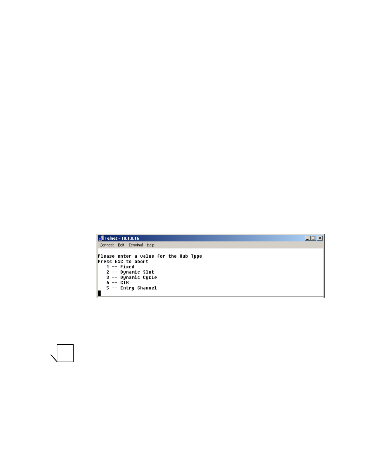
Hub Type
This menu item is only displayed if the CDM-570/570L is being used as a Hub
in the network. Vipersat STDMA has five modes of operation:
• Fixed - All remotes get the same size slot, regardless of each remote’s
activity
• Dynamic Slot - Slot size is adjusted each cycle depending on activity
during the previous cycle
• Dynamic Cycle - A dynamic cycle allows changing the cycle time, and
corresponding latency, as loads change always providing minimum
latency for the current traffic load.
• GIR - Guaranteed Information Rate allows assigning a guaranteed data
rate to a channel.
• Entry Channel - Entry channel mode provides an on-demand channel for
applications such as a mobile remote.
Figure 3-8
Hub Type prompt
Entering a number from 1 to 5 at the command prompt determines the bandwidth allocation mode for the Hub CDM-570/570L.
Note: If the selected Hub STDMA mode is GIR (Guaranteed Information
Rate) or Entry Channel, normal load switching is automatically
disabled. In GIR mode, the Remote is switched to SCPC as soon
as the GIR threshold is reached, if there is a switch rate defined.
In Entry Channel mode, the Remote is switched to SCPC as soon
as the Hub receives the first transmission from the Remote.
Refer to Appendix B, "Automatic Switching" for details on how each of the
bandwidth allocation modes functions and the parameters and processes used to
calculate the commands for each mode.
NOTE
Page 44

Vipersat Configuration
3-10 Vipersat CDM-570/570L User Guide
1 -- Fixed
In the Fixed mode, all remotes have the same slot size regardless of type of traffic or load.
2 -- Dynamic Slot
In the Dynamic Slot mode, the slot size for each remote is computed based on
the time (at the current data rate) needed to transmit all the Bytes in Queue. If
the result is less than the minimum slot size or more than the maximum slot
size, the slot is adjusted accordingly.
3 -- Dynamic Cycle
In the Dynamic Cycle bandwidth allocation method, available bandwidth is
allocated to remotes proportionally based on their current bandwidth needs. The
bandwidth requirements are determined by the number of bytes in queue for
each remote divided by the total number of bytes in queue for all remotes to
determine the percentage of bandwidth to allocate for each remote.
4 -- GIR
In the GIR mode, the initial computed slot size value is the same as the
Dynamic Cycle mode except there is no maximum limit. After all remotes have
been assigned slots, the burst map is checked to see if the total cycle length
exceeds 1 second. If not, then all requirements are satisfied and the burst map is
complete. However, if the cycle is greater than one second, then the slots are
adjusted proportionally so that all remotes receive at least their guaranteed rate
plus whatever excess is still available.
In this software version, when the 1 second restriction is exceeded, remotes
without a specified GIR are reduced to the global minimum slot size and the
remaining bandwidth is distributed to remotes that have been assigned a GIR
rate. Remotes assigned a GIR are given available excess bandwidth when
needed.
Note: GIR allocations are restricted so that assigned GIR totals cannot
exceed the available bandwidth to insure proper bandwidth allocation when the network is overloaded.
5 -- Entry Channel
The Entry Channel mode is the same as Dynamic Cycle mode, except that as
soon as the hub receives an STDMA ACK, it initiates a switch to SCPC mode
based on the policy set for that remote.
NOTE
Page 45

Chapter 3 - Using the Command Line Interface (CLI) 3-11
Vipersat Configuration
This mode is designed to accommodate the needs of a remote which will not be
continuously connected to the network, but which has the need to be able to
make an on-demand connection when required, such as a mobile remote.
Note that the switch occurs as soon as the hub receives an STDMA ACK even
though there may not be traffic at that time. The persistence of the link will be
determined by the unit’s flag settings.
Refer to Appendix B, "Automatic Switching" for details on this switching
mode.
Group ID
The STDMA group ID number defines a group of equipment which will
respond to the output of the burst controller. This group is addressable within a
network which, in turn, is defined by the network ID number assigned to the
CDM-570/570L.
Note: The STDMA group number and the network ID are independent.
There can be multiple STDMA groups within a single network.
Figure 3-9
Group ID prompt
The target CDM-570/570L group ID can be modified by entering an I at the
command prompt to display the dialog shown in figure 3-9.
Low Data Rate Fast Acquisition
This menu item is a toggle used to enable or disable the Vipersat Burst Fast
Acquisition Timing (BFAT) feature that functions at low data rates (64 kbps to
256 kbps). Entering A at the command prompt will toggle this feature On or
Off.
This feature requires Base Modem firmware version 1.5.2 or later, together with
Router firmware version 1.5.3 or later.
Burstmap Multicast IP
This menu item is used to define the IP address for the Burstmap Multicast that
is sent out by the STDMA burst controller at the Hub to all of the associated
remotes in that group. This address must be the same for all members of the
NOTE
Page 46

Vipersat Configuration
3-12 Vipersat CDM-570/570L User Guide
group. The burstmap is a proprietary message sent from the Hub to all remotes,
at regular intervals, specifying the relative start time and duration for each
terminal to transmit.
To change the current address, enter N at the command prompt to display the
dialog shown in figure 3-10.
Figure 3-10
Burstmap Multicast IP prompt
Outbound IP
This menu item, which appears for all Hub configurations, displays the current
Outbound IP address. This specifies the Hub device that is supplying the TDM
outbound to the satellite (typically a CDM-570/570L). Specifying this address is
necessary when configuring a Hub that utilizes a burst controller that is a separate device from the TDM modem.
To change the target address of the TDM outbound for DPC messages for the
STDMA controller, enter O at the command prompt to display the dialog shown
in figure 3-11.
Figure 3-11
Outbound IP prompt
Cycles Per Burst Map
This menu item, which appears for all Hub types except Dynamic Cycle and
GIR, displays the number of spin cycles that occur prior to each broadcast of the
burstmap. This parameter can be modified from the Hub CDM-570/570L by
entering a C at the command prompt as shown in figure 3-12. For Dynamic
Cycle and GIR configurations, the number of cycles is automatically set to one
in order to ensure optimum performance for these Hub types.
On Remote units, this menu item is an information-only display.
Page 47

Chapter 3 - Using the Command Line Interface (CLI) 3-13
Vipersat Configuration
Figure 3-12
Cycles per Burst Map prompt
Slot Guardband
This menu item displays the current length of the slot guardband in milliseconds and the size of the guardband in bytes for the target CDM-570/570L.
Figure 3-13
Slot Guardband prompt
On a Hub unit, this value can be modified by entering G at the command
prompt to display the dialog shown in figure 3-13 and entering a new value.
On Remote units, this menu item is an information-only display.
Note: Note that the value you enter at the command line in figure 3-13
is in milliseconds. The corresponding value expressed in bytes is
calculated by the CDM-570/570L based on the STDMA transmit
bit rate as shown in the menu in figure 3-6.
Slot Preamble Length
This menu item displays the current slot preamble size in milli-seconds and
bytes for the target CDM-570/570L.
Figure 3-14
Slot Preamble Length prompt
On a Hub unit, entering P at the command prompt allows changing the preamble duration in milliseconds.
On Remote units, this menu item is an information-only display.
NOTE
Page 48

Vipersat Configuration
3-14 Vipersat CDM-570/570L User Guide
Note: Refer to the Viper Calculator for determining preamble length
values to enter at the command prompt. If you not have a copy of
the latest Viper Calculator, contact your Comtech Vipersat
Networks representative to inquire about a copy.
Slot Data Length
This menu item displays the Slot Data Length in milli-seconds and bytes for the
target CDM-570/570L, and represents the amount of data that can be transmitted or received in one spin of the STDMA cycle by each of the Remotes belonging to that group.
Depending on the Hub type that is defined for the modem, the appearance of
this parameter will vary:
• Fixed – Slot Data Length
• Dynamic Slot – Nominal Data Length, Minimum Data Length
• Dynamic Cycle – Maximum Data Length, Minimum Data Length
• ECM & GIR – Minimum Data Length
On a Hub unit, entering B and M at the command prompt brings up the dialogs
for specifying the data length in milli-seconds for the target CDM-570/570L, as
shown in figure 3-15.
On Remote units, this menu item is an information-only display.
Figure 3-15
Slot Data Length (Nominal)
Slot Cycle Length
This menu item is for information only and displays the slot cycle length in
milli-seconds and bytes for the target CDM-570/570L. This value represents the
total amount of time (preamble, data length, and guardband) allocated to the
remote modem during one spin cycle.
NOTE
Page 49

Chapter 3 - Using the Command Line Interface (CLI) 3-15
Vipersat Configuration
Slot Start in Cycle
This menu item is an information-only display for Remote modems, and indicates how much time passes from the start of the spin cycle until this Remote is
provided a time slot. In the example shown in figure 3-7, the Remote is
provided the first slot in the cycle (0 mSec).
Set Remotes
This menu item appears in the STDMA screen when the Unit Role is Hub.
From a Hub CDM-570/570L, entering R at the command prompt displays the
STDMA Remotes Menu.
Figure 3-16
STDMA Remotes Menu screen
The menu shown in figure 3-16 is used to define and make modifications to the
Remotes that belong to the STDMA group for the Hub modem, as well as to
display each Remote’s burstmap status information.
Adding a Remote to the STDMA Group
Entering the item number for the Remote modem/router brings up the dialog
shown in figure 3-17. A prompt to enter the Name for the Remote unit appears,
followed by a prompt to enter the IP Address.
Page 50

Vipersat Configuration
3-16 Vipersat CDM-570/570L User Guide
Figure 3-17
Adding a Remote to the STDMA group
Once a Remote has been added to the group, its Status in the group is displayed
by the use of the following letters:
• U = Used – This Remote is being used in the burstmap
Once a remote has been added to the STDMA group, this status will
always be displayed.
• B = Burstmap – This Remote is currently in the burstmap
This status will be displayed unless the remote has been removed (R),
disabled (D), or switched (S) out of the STDMA burstmap.
• R = Removed – This Remote is currently removed from the burstmap.
When displayed, this status indicates that the Hub has removed this remote
from the burstmap due to a communications fault.
• D = Disabled – This Remote is currently disabled and is not in the
burstmap.
This status will be displayed when a remote is manually disabled by the
operator or administrator.
• S = Switched – This Remote is currently switched into SCPC mode.
When displayed, this status indicates that the VMS has automatically
switched the remote out of the burstmap and into SCPC operation.
Base
Entering a B at the command prompt in figure 3-16 allows entering the Remote
number to start displaying remotes in this menu screen. Entering the number 1,
as shown in figure 3-16, displays nine remotes, 1 through 9. If the number 4 had
been entered, the display would show the nine remotes starting with remote 4
(i.e., remotes 4 through 12).
Figure 3-18
Modifying Remote Display Base
Page 51

Chapter 3 - Using the Command Line Interface (CLI) 3-17
Vipersat Configuration
Remote Count
The Remote Count menu item in figure 3-16 is an information only display
showing the total number of Remotes that currently belong to the STDMA
group for this Hub modem.
Set Remote Policies
This menu item, which appears for GIR and Entry Channel Hub types, allows
each Remote to be configured for specific data switching conditions. Entering P
at the STDMA Remotes Menu command prompt displays the Remote Policies
screens shown in either figure 3-19 (GIR Hub) or figure 3-21 (Entry Channel
Hub).
Figure 3-19
STDMA Remote Policies screen (GIR Hub)
Entering the Remote number at the command prompt in figure 3-19 allows the
Guaranteed Information Rate and the Automatic Load Switch Rate for that
Remote to be set, as shown in figure 3-20. Note that the Available Bandwidth is
displayed for reference in this screen to assist with entering the appropriate
rates. The cycle length for GIR is limited to a maximum of one second.
Figure 3-20
GIR Remote Policies prompt
Page 52

Vipersat Configuration
3-18 Vipersat CDM-570/570L User Guide
The Remote Policies screen for an Entry Channel Hub type allows the SCPC
data rates and switch types to be specified for when a Remote will switch and
the desired starting point for communications.
Figure 3-21
Entry Channel Switch Rates screen
Entering the Remote number at the command prompt in figure 3-21 allows the
SCPC Data Rate and the Switch Type for that Remote to be set, as shown in
figure 3-22. Switch type 0 corresponds to Load Switching; switch types 64
through 255 are user-defined, and must match VMS policies.
Figure 3-22
Remote SCPC Data Rate and Switch Type prompt
The Global SCPC Rate command can be used to set the data rate for all or a
majority of the Remotes. This allows the rate to be entered just once instead of
entering the rate for each remote individually. Enter G at the command prompt.
Figure 3-23
Global SCPC Data Rate prompt
Similarly, the Global Switch Type command can be used to set the switch type
for all or a majority of the Remotes. Enter H at the command prompt.
Page 53

Chapter 3 - Using the Command Line Interface (CLI) 3-19
Vipersat Configuration
Figure 3-24
Global Switch Type prompt
Delete Remote
Entering D at the command prompt shown in figure 3-16 brings up the Delete
Remote dialog shown in figure 3-25.
Figure 3-25
Delete Remote prompt
Enter the number of the Remote CDM-570/570L at the command prompt to
delete it from the STDMA group for this Hub modem.
Enable/Disable Remote
Enter E at the command prompt in figure 3-16 to display the dialog shown in
figure 3-26. The Remotes in the STDMA group are displayed, indicating
whether each is currently Enabled (E) or Disabled.
Figure 3-26
Enable/Disable Remote prompt
Enter the number of the Remote at the command prompt to toggle the Remote
from its current Enable/Disable configuration.
View Remote(s)
Entering V at the command prompt shown in figure 3-16 will display the listing
of Remote(s) that belong to the STDMA group for this Hub modem, as shown
in figure 3-27.
Page 54

Vipersat Configuration
3-20 Vipersat CDM-570/570L User Guide
Figure 3-27
View Remote(s) screen
The display is for information only and pressing any key will return you to the
menu shown in figure 3-16.
Remove Timeout
Entering R at the command prompt shown in figure 3-16 will display the
Remove Timeout dialog shown in figure 3-28. Note that the menu item shown
in figure 3-16 shows the current setting (in seconds) for this parameter.
Figure 3-28
Remove Timeout prompt
The value entered at the command prompt in figure 3-28 defines the amount of
time (in seconds) with no communication from a Remote to the Hub before that
Remote is removed from the Burstmap. This feature is useful, for example, in an
SNG application where a mobile remote has finished its assignment and has
shut down.
If communications are lost for this period of time, the Remote is removed from
the STDMA group, and the bandwidth resources it had been allocated are then
made available for use by the other remotes remaining in the group.
Remove Retry Timeout
Entering T at the command prompt in figure 3-16 will display the Remove
Retry Timeout dialog shown in figure 3-29.
Page 55

Chapter 3 - Using the Command Line Interface (CLI) 3-21
Vipersat Configuration
Figure 3-29
Remove Retry Timeout prompt
When a Remote is removed from the STDMA group, as described in the section
“Remove Timeout” above, entering a value in the Remove Retry Timeout
dialog above defines the amount of time (in seconds) that is allowed to pass
before a retry attempt is made to return the removed Remote to the group.
This allows, again using a mobile remote as an example, shutting down the
remote at one location, moving it to a new location, and then automatically reestablishing a connection to the satellite network.
STDMA Statistics
Entering V at the command prompt on the STDMA screen displays the
STDMA Statistics as shown in either figure 3-30 (Hub) or figure 3-31
(Remote). These screens provide information for the number of Bursts (Remote
only), number of Burst Maps, and the current STDMA Cycle Length.
Because the Remote modem bursts back to the Hub once every cycle, the
number of Bursts displayed should be a multiple of the number of Burst Maps
displayed, with this multiple determined by the number of cycles per burst map
(1, 2, or more) that has been defined at the Hub. For the example shown in
figure 3-31 (Dynamic Cycle), the number of cycles per burst map is one, and
therefore the number of Bursts equals the number of Burst Maps.
Figure 3-30
STDMA Statistics screen (Hub)
Page 56

Vipersat Configuration
3-22 Vipersat CDM-570/570L User Guide
Figure 3-31
STDMA Statistics screen (Remote)
The window of time that is used to average the accumulation of statistics can
be set by entering W at the command prompt in the Hub screen, then entering
the number of seconds (from 1 to 20).
To clear (reset to 0) these statistics, enter C at the command prompt.
Show Hub Statistics
Entering a W at the command prompt in the STDMA screen (figure 3-6)
displays the current statistics for the target CDM-570/570L Hub, as shown in
figure 3-32.
Figure 3-32
Hub Statistics screen
The Burst Controller monitors statistics in the received ACK from each Remote.
The statistics report the fill status of the STDMA buffers. The Burst Controller
builds a table of the group and calculates the relative buffer fill for each Remote.
It then calculates the length of the Data Slot for each Remote based on the Minimum Slot Size plus a percentage of the Available Bandwidth. Idle remotes
would receive a Data Slot equal to the Minimum Slot Size.
In the figure 3-32, Remote 1 with IP address 10.1.128.1 had activity during the
averaging period. It captured 37.8% of the total slot time and had an average
slot length of 283 ms. Remotes 2, 3, and 4 had 41.5%, 18.1%, and 7.6% respectively. The dynamic range of STDMA is a function of the difference between
Page 57

Chapter 3 - Using the Command Line Interface (CLI) 3-23
Vipersat Configuration
the Nominal Data Slot Size and the Minimum Data Slot Size parameters. These
parameters are operator selectable. The speed with which STDMA reacts to
changes in dynamic load is a function of the Statistics Accumulation Window
parameter and the Cycles per Burst Map parameter, both of which are also operator selectable.
STDMA/SCPC Automatic Switching
One of the most powerful features of the Vipersat CDM-570/570L is the capability to perform automatic switching between STDMA mode and SCPC mode
based on bandwidth demand. The configuration options that are available to
meet customer-specific requirements are extensive, and include switching based
on Load, Application (Voice and Video RTP), ToS, and QoS.
Note: Care must be taken when configuring the Auto Switching features
of the Vipersat system to ensure that there is no duplication or
overlap of switching functions between Application, ToS, and
QoS for a particular traffic flow. Only one of these switching methods should be utilized for any one flow requirement.
The functions available for configuring the switching operations depend on
whether the target CDM-570/570L is a Hub unit or if it is a Remote unit.
In order for the target CDM-570/570L to be automatically switched between
SDTMA and SCPC modes, the Auto Switching feature must be enabled as
described in the section “Feature Configuration” on page 3-4.
Selecting Automatic Switching from the Vipersat Configuration screen
shown in figure 3-5 will display the STDMA/SCPC Auto Switching screen
shown in either figure 3-33 (Hub modem) or figure 3-34 (Remote modem).
Figure 3-33
STDMA/SCPC Auto Switching screen (Hub)
NOTE
Page 58

Vipersat Configuration
3-24 Vipersat CDM-570/570L User Guide
Figure 3-34
STDMA/SCPC Auto Switching screen (Remote)
Auto Switching
The Auto Switching item is for information only and shows the current configuration of the target CDM-570/570L. This feature is Enabled and Disabled as
described in section “Feature Configuration” on page 3-4. Auto Switching must
be Enabled in order to utilize any of the related features/commands in this
menu.
Current WAN Transmit Mode
The Current WAN Transmit Mode item is for information only and reflects
the current status of the CDM-570/570L. If the CDM-570/570L is functioning
as a Hub in the network, this item will always read Continuous as shown in
figure 3-33. If the CDM-570/570L is functioning as a Remote in the network
and STDMA is enabled on the target CDM-570/570L, this item will show
STDMA (Burst) as shown in figure 3-34.
Tip: This menu item is useful for determining whether a Remote modem is
currently operating in STDMA or SCPC mode.
Voice & Video Application Switching
One of the four automatic switching functions that the Vipersat CDM-570/570L
is able to perform is Application Switching. The Vipersat CDM-570/570L
provides application switching for non-encrypted SIP and/or H.323 traffic that
is detected on the satellite network. When encryption prevents the detection of
this type of traffic, an alternate means of SCPC switching can be configured
using the ToS auto switching feature.
Page 59

Chapter 3 - Using the Command Line Interface (CLI) 3-25
Vipersat Configuration
Detection of the voice and video traffic occurs in the Remote modem classifier,
which looks at traffic that is passed in both directions (Hub-to-Remote and
Remote-to-Hub). Once the Voice and Video Switch Detection features are
enabled, the Remote modem will send an Automatic Switch Request (ASR) to
the VMS when an SIP and/or H.323 call is detected. The ASR contains the
destination IP address of the RTP packets. If available hardware and bandwidth
exist, the VMS will establish the SCPC carrier automatically.
Note: Application switching (voice and video) must be enabled for each
CDM-570/570L in a network that is going to perform application
switching in order for the VMS to dynamically optimize network
circuit parameters to accommodate these applications.
Load switching by the VMS is not affected by this setting.
Voice Switch Detection
This menu item appears for Remote modems only.
Voice Switch Detection is one of the Application switching commands that
provides for a dedicated SCPC connection when an SIP and/or H.323 voice call
is made over the satellite network.
Entering O at the command prompt toggles the Voice Switch Detection
command for the CDM-570/570L between Enabled and Disabled. When
enabled, a voice data-stream will be detected, causing the CDM-570/570L to
send a switch request to the VMS to switch from STDMA to SCPC mode.
Video Switch Detection
This menu item appears for Remote modems only.
Video Switch Detection is one of the Application switching commands that
provides for a dedicated SCPC connection when an H.323 video call is made
over the satellite network.
Entering I at the command prompt toggles the Video Switch Detection
command for the CDM-570/570L between Enabled and Disabled. When
enabled, a video data-stream will be detected, causing the CDM-570/570L to
send a switch request to the VMS to switch from STDMA to SCPC mode.
ToS Switch Detection
This menu item appears for Remote modems only.
One of the four automatic switching functions that the Vipersat CDM-570/570L
is able to perform is ToS (Type of Service) Switching. ToS is defined by an
eight bit field within an IP packet header that is used to set up per-hop-based
QoS rules for prioritizing packets. Because the ToS field remains untouched by
NOTE
Page 60

Vipersat Configuration
3-26 Vipersat CDM-570/570L User Guide
most encryption methods, ToS switching provides an alternative means of
SCPC switching when encryption prevents the detection of SIP and H.323
protocols.
ToS detection occurs in the Remote modem classifier which only looks at traffic
that is passed in the LAN-to-SAT (Remote to Hub) direction. Once the ToS
Switch Detection feature is enabled, the Remote modem will send an ASR to
the VMS when a packet stamped with the ToS is detected. The ASR contains
the destination IP address of the ToS stamped packet, the desired SCPC rate,
and the VMS Switch Type (policy #). If available hardware and bandwidth
exist, the VMS will establish the SCPC carrier automatically.
Entering T at the command prompt in figure 3-34 toggles the TOS Switch
Detection command for the CDM-570/570L between Enabled and Disabled.
When enabling ToS switching, the ToS switching control parameters must be
defined as described in the section “ToS Switching Parameters” on page 3-32.
Applying a ToS value to an application (VoIP, IPVC, or priority data) through
either preservation or classification packet stamping allows the Vipersat switching system to function in an encrypted network. Normally in a non-encrypted
Vipersat network, packets are classified by the Remote CDM-570/570L using
protocol classification detection and the results are forwarded to VMS via
VESP (Vipersat External Switching Protocol) or, in legacy VMS systems, via
an ASR (Automatic Switch Request) message. The VMS switch detector
service then applies the required or requested bandwidth using policies which
have been pre-configured in the VMS. Refer to the VMS User’s Guide for
details.
For example, if in a non-encrypted network a voice application service connection is started, the CDM-570/570L’s classifier analyzes signaling and data
protocols (H.323, SIP, & Data RTP) being routed through the CDM-570/570L.
After connection detection, the process waits for data (RTP). Data is normally
sent after the receiving party answers, which then triggers the system to process
an ASR. Using the ToS classification, the detection function allows applicationbased switching in encrypted networks where the signaling protocols are
encrypted or effectively hidden.
Note: Load switching by the VMS is not affected by enabling ToS detec-
tion.
QoS Switch Detection
This menu item appears for Remote modems only.
One of the four automatic switching functions that the Vipersat CDM-570/570L
is able to perform is QoS (Quality of Service) Switching. With this feature, an
STDMA to SCPC switch can be initiated based upon any type of IP traffic flow
that matches a defined QoS queue. QoS detection occurs in the Remote modem
NOTE
Page 61

Chapter 3 - Using the Command Line Interface (CLI) 3-27
Vipersat Configuration
classifier, which looks at traffic that is passed in both directions (Hub-toRemote and Remote-to-Hub). When an IP packet matches a defined QoS rule,
the Remote modem sends an ASR to the VMS that contains the destination
address of the detected packet, the defined bit rate, and the policy type. If available hardware and bandwidth exist, the VMS will establish the SCPC carrier
automatically.
Enable Quality of Service (QoS) Feature
The Remote must have the QoS FAST feature code, and the QoS feature must
be enabled in order for the QoS Switch Detection feature to function. The QoS
feature is Enabled/Disabled from the Feature Configuration screen (see
figure 2-3).
Configure QoS Rules
The Vipersat CDM-570/570L is capable of performing automatic switching
based on the QoS rules for a Remote modem. QoS rules can be assigned to
different flow types that are user-defined by any combination of traffic type
protocol (FTP, UDP, RTP, etc.), source/destination IP (specific or range), and/
or Layer 3 source/destination port.
The Vipersat QoS Switching feature is designed to manage single, specific
sessions or flow types, such as a UDP video stream targeted to a specific port.
When defining QoS rules for QoS based switching, it is best to make them as
specific as possible so as to avoid unintended or multiple sessions/flows being
generated with that rule. A QoS rule that creates multiple flows will result in
poor switching performance. With voice traffic, for example, prioritize by using
the VOCE protocol rather than prioritizing with RTP or UDP.
From the Main Menu for the Remote modem, enter Q to access the QoS
Configuration screen, as shown in figure 3-35.
Page 62

Vipersat Configuration
3-28 Vipersat CDM-570/570L User Guide
Figure 3-35
QoS Configuration screen
Enter Q at the command prompt in figure 3-35 to access the QoS Rules Config-
uration screen, as shown in figure 3-36.
Figure 3-36
QoS Rules Configuration screen
Configure the desired number of rules that are necessary for the applications to
be used for this network. Refer to the CDM-570/570L Installation and Opera-
tion Manual for details on configuring QoS Rules for the CDM-570/570L.
Configure QoS Rules Based Switching
Enter V at the command prompt in figure 3-35 to access the QoS Rules Based
Switching screen for the Remote modem, as shown in figure 3-37
Page 63

Chapter 3 - Using the Command Line Interface (CLI) 3-29
Vipersat Configuration
Figure 3-37
QoS Rules Based Switching screen
Determine which QoS rules will be used as a basis for performing SCPC
switching, then configure the VMS policy type, the SCPC switch rate, and the
timeout value to be associated with each rule. Assigning a 0 (zero) value means
that no SCPC switch will occur for that rule.
Enable QoS Switch Detection Feature
Once QoS has been enabled and configured as described above, the last step in
implementing QoS switching is to Enable the QoS Switch Detection feature.
Entering Q at the command prompt in figure 3-34 toggles the QoS Switch
Detection feature between Enabled and Disabled.
Load Switching
One of the four automatic switching functions that the Vipersat CDM-570/570L
is able to perform is Load Switching. The system will detect variations in data
rate and can be configured to switch from STDMA to SCPC based on bandwidth requirements.
The initial switch for a Remote CDM-570/570L from STDMA mode to SCPC
mode is determined by the Hub Burst Controller. Once the Remote is switched
into SCPC, any requests to meet additional switching requirments within SCPC
(Step Up or Step Down) are made by the Remote modem.
The Load Switching command on the Auto Switching menu is a toggle that
Enables and Disables Load Switching on the target CDM-570/570L. Entering
L at the command prompt will toggle between these two states. Refer to Appen-
dix B, Automatic Switching, in this document for additional information on
Load Switching.
Page 64

Vipersat Configuration
3-30 Vipersat CDM-570/570L User Guide
Note: Load Switching must be enabled for each CDM-570/570L in a
network that is going to perform Load Switching in order for the
VMS to dynamically optimize network performance as load conditions change on these circuits.
Application switching by the VMS, such as for Voice and/or
Video, is not affected by this setting. However, using Load
Switching for real-time applications is not recommended.
STDMA Slot Capacity
This menu item appears for Hub modems only.
The STDMA Slot Capacity command allows setting the threshold or level of
slot capacity at which the Burst Controller sends a switch request to the VMS to
switch the Remote from STDMA mode to SCPC mode.
Typically the default settings will be optimum, but there may be unique network
configurations that require modifying the STDMA slot capacity value. To
change this setting, enter U at the command prompt in figure 3-33 to display the
screen shown in figure 3-38.
Figure 3-38
STDMA Slot Capacity prompt
STDMA Switch Delay
This menu item appears for Hub modems only.
In order to minimize unnecessary switching from STDMA to SCPC due to transient conditions, such as a temporary spike in network traffic for example, a
switch delay parameter is provided.
Typically the default values will be optimum, but this value can be changed to
accommodate a unique network configuration or application. To change this
setting, enter W at the command prompt in figure 3-33 to display the screen
shown in figure 3-39.
NOTE
Page 65

Chapter 3 - Using the Command Line Interface (CLI) 3-31
Vipersat Configuration
Figure 3-39
STDMA Switch Delay prompt
Percent Allocation
The Percent Allocation menu item allows adding a fixed percentage to the
channel bandwidth request to accommodate additional bandwidth requirements
which may occur after the switch is made from STDMA to SCPC mode.
Typically the default value will be optimum, but if there may be a larger bandwidth requirement after the switch, the percent allocation value can be
increased. In choosing a value for this allocation, future bandwidth requirements for the channel must be balanced against efficient bandwidth utilization.
To change this setting, enter E at the command prompt in figure 3-33 to display
the screen shown in figure 3-40.
Figure 3-40
Percent Allocation prompt
SCPC Step Up Threshold
This menu item appears for the Remote modem only.
The SCPC Step Up Threshold establishes the percentage of bandwidth use
that will trigger a switch up from the present SCPC rate to a higher rate to
ensure that there is sufficient bandwidth available for current conditions.
Typically the default value will be optimum, but if a different threshold is
desired, an alternate value can be specified by entering U at the command
prompt in figure 3-34. Note that this value must be greater than the value specified for the SCPC Step Down Threshold.
SCPC Step Down Threshold
This menu item appears for the Remote modem only.
Page 66

Vipersat Configuration
3-32 Vipersat CDM-570/570L User Guide
The SCPC Step Down Threshold establishes the percentage of bandwidth use
that will trigger a switch down from the present SCPC rate to a lower rate to
ensure efficient bandwidth usage.
Typically the default value will be optimum, but if a different threshold is
desired, an alternate value can be specified by entering D at the command
prompt in figure 3-34. Note that this value must be less than the value specified
for the SCPC Step Up Threshold.
SCPC Step Delay
This menu item appears for the Remote modem only.
The SCPC Step Delay feature provides a switching delay period to ensure that
a premature switch up or down in the SCPC rate does not occur due to a temporary rise or fall in traffic.
A default value (in seconds) is provided, but this parameter can be modified by
entering W at the command prompt in figure 3-34.
SCPC Step Up Excess
This menu item appears for the Remote modem only.
During each SCPC Step Up switch, the excess capacity data rate value entered
by this command is added to the new SCPC data rate. This excess is added each
time an SCPC Step Up switch occurs. This setting makes additional bandwidth
available for when the demand arises while minimizing step up switching
events.
A default percentage value is provided, but this parameter can be modified by
entering E at the command prompt in figure 3-34.
ToS Switching Parameters
This menu item appears for the Remote modem only.
When ToS switching is enabled on a CDM-570/570L, the parameters for ToS
switching must be defined by entering P from the STDMA/SCPC Auto Switching screen (see figure 3-34). The TOS Switching Control menu shown in
figure 3-41 is displayed, allowing parameter entry for the desired ToS service to
be applied.
Page 67

Chapter 3 - Using the Command Line Interface (CLI) 3-33
Vipersat Configuration
Figure 3-41
ToS Switching Control screen
ToS Switching Entry
After determining what ToS value to use, either application or router classifier,
select a ToS entry from the list for configuration or edit. The screen will prompt
for inputs to the list of range-checked values, as shown in the sample dialog in
figure 3-42 that displays the entries for TOS 03.
Figure 3-42
ToS Switching Entry dialog
• Enter Name for TOS ID [ ] - At the prompt, enter a user-defined text
label for circuit identification.
• Enter the TOS ID - Enter an integer value in the range of 1 to 63.
Entering a value of 0 will result in no switch.
• Enter the Switch Type - Enter an integer value in the range of 64 to 254
at the prompt to inform the VMS what switching policy to use. Entering a
value of 0 will result in no switch.
Page 68

Vipersat Configuration
3-34 Vipersat CDM-570/570L User Guide
• Enter the TOS SCPC Switch Data Rate - Enter the desired data rate for
this service type. Valid entries are from 0 to 10,000 Kbps. This setting will
override the VMS set policy value.
• Enter the TOS SCPC Timeout - This timer monitors the defined packet
flow. Once data stops for the duration of the timer setting, the link state
will be restored to the home state condition. Valid entries are from 1 to 60
seconds.
After entering the timeout value, pressing the Enter key will update the TOS
Switching Control menu with the changes.
Delete
Enter D at the command prompt in figure 3-41 to Delete a ToS entry, as shown
in figure 3-43.
Figure 3-43
ToS Delete prompt
Note: The value shown in the TOS Value column is the TOS ID associ-
ated with the ToS entry to be deleted.
View
Entering a V at the command prompt will display the Internal TOS Table for
active entries as shown in figure 3-44.
Note that, due to binary conversion, the ID value is a multiple of 4 and the
Timout value is a multiple of 2.
Figure 3-44
ToS View screen
NOTE
Page 69

Chapter 3 - Using the Command Line Interface (CLI) 3-35
Vipersat Configuration
Unit Role
The Unit Role configuration determines whether the target CDM-570/570L is
to function as a Remote or as a Hub in the Vipersat satellite network. From the
Vipersat Configuration screen (figure 3-5), enter R to display the dialog
shown in figure 3-45.
Figure 3-45
Unit Role prompt
The choice made in this command will determine the role the target CDM-570/
570L will perform in the network and what type of commands and functions it
will receive from the VMS.
Expansion Unit
The Expansion Unit menu item in the Vipersat Configuration screen
(figure 3-5) defines whether the target CDM-570/570L is to function as an
Expansion Unit (the demod configured to operate in SCPC mode) or not. Entering E at the command prompt will display the dialog shown in figure 3-46.
Figure 3-46
Expansion Unit prompt
The VMS uses this data when monitoring and controlling the network to determine the target CDM-570/570L’s function. When configured as an expansion
unit, either as a Hub (switched) or as a Remote (mesh), the CDM-570/570L is
set up so that the demod is in SCPC mode and available as a resource for dedicated communications with the other end of the satellite link.
Page 70

Vipersat Configuration
3-36 Vipersat CDM-570/570L User Guide
Network ID
The Network ID that is assigned to the unit defines to what network the target
CDM-570/570L will belong. All units used in a network will have the same
Network ID. Enter B at the command prompt in the Vipersat Configuration
screen (figure 3-5) to display the dialog shown in figure 3-47.
Figure 3-47
Network ID prompt
The Network ID is used by the VMS to identify units that are common to a
network and allows the VMS to manage multiple networks, each with its own
unique Network ID number.
Unit Name
The Unit Name command in the Vipersat Configuration screen (figure 3-5) is
used to assign a name to the target CDM-570/570L. Enter N at the command
prompt to display the dialog shown in figure 3-48. Any name, up to 16 characters, can be entered for the unit.
Figure 3-48
Unit Name prompt
This name is displayed by the VMS and identifies the unit in the graphical
network display.
Receive Multicast Address
The Receive Multicast Address is the multitcast IP address assigned to the
VMS and and all CDM-570/570L units in the network. When the CDM-570/
570L receives a multicast from the VMS server, it receives the server’s IP
address and responds to the VMS server with a unicast containing its current
Page 71

Chapter 3 - Using the Command Line Interface (CLI) 3-37
Vipersat Configuration
configuration data, including the CDM-570/570L’s IP address. When the VMS
receives the unicast response, it registers the CDM-570/570L on the network.
Enter V at the command prompt in the Vipersat Configuration screen
(figure 3-5) to display the dialog shown in figure 3-49.
Figure 3-49
Receive Multicast IP Address prompt
Switch requests can be unicast to the VMS server and unicast switch commands
received from the VMS by the CDM-570/570L. For more information on this
process, refer to the VMS User Guide.
Managing IP Address
The Managing IP Address command in the Vipersat Configuration screen
(figure 3-5) allows the IP address for the server running VMS to be entered.
Enter I at the command prompt to display the dialog shown in figure 3-50.
Figure 3-50
Managing IP address menu
If available, this is the IP address to which the CDM-570/570L sends a unicast
registration request every 60 seconds when requesting initial registration on the
VMS network. Later the CDM-570/570L uses this address to send switch
requests, network health messages, etc. to the managing VMS server.
Primary Heart Beat
This menu item appears for the Hub modem only.
The Primary Heart Beat feature is a redundancy heart beat message for primary
Hub units that provides the option for a periodic communications check
message to be sent from the Hub modem to the VMS for backup recovery in
Page 72

Vipersat Configuration
3-38 Vipersat CDM-570/570L User Guide
N:M redundancy (protected) configurations. The message interval can be specified by the administrator through the VMS.
Enter P at the command prompt in the Vipersat Configuration screen
(figure 3-5) to toggle this feature between Enabled and Disabled.
Home State Revert
This menu item appears for the Remote modem only.
The Home State Revert feature allows automatic resource recovery to be
performed on SCPC connections when a communications failure occurs
between the VMS and a Remote, such as a rain fade condition, a Remote unit
power down, or a hardware failure. The period of time (in minutes) for a failure
is configured in the VMS for each Remote in the network. Should communications be lost for more than the specified time period, the Remote will automatically revert to its Home State settings and the VMS will remove all allocated
resources (bandwidth, demod(s)), freeing them for use by any other Remote in
the network.
Because this feature is configured in the VMS, the status (Enabled or Disabled)
appears as an information-only display in the Vipersat Configuration menu
(figure 3-5).
Dynamic Power Control Configuration
Dynamic Power Control (DPC) is a Vipersat feature that acts to regulate the
transmit power of the Vipersat satellite modem, such that the specified receive
signal level (Eb/No) is met for the receiving Vipersat units in the group. DPC is
driven by the receiver demod, which notifies the transmitting modem of the
current Eb/No value.
Refer to Appendix C, Dynamic Power Control, in this document for additional
information on the DPC feature.
The Dynamic Power Control Configuration screen (enter C in the Vipersat
Configuration menu) allows for setting the parameters for the CDM-570/570L
power levels. The information and commands in the menu will vary depending
on the function that the target CDM-570/570L performs in the network. The
screen shown in figure 3-51 is for a Hub or Remote operating in STDMA mode.
For comparison, the DPC Config screen for a unit operating as a Hub or Remote
with Expansion (SCPC mode) is shown in figure 3-52. Note that only the applicable settings appear in this screen.
Page 73

Chapter 3 - Using the Command Line Interface (CLI) 3-39
Vipersat Configuration
Figure 3-51
DPC Configuration screen (STDMA mode)
Figure 3-52
DPC Configuration screen (SCPC mode)
Note: The following descriptions will refer to the CDM-570/570L as
either modulator or demodulator for simplicity and understanding.
Before enabling DPC, the operator should verify that a demodulator at another
terminal is receiving from this modulator, and that there is a working communications channel from that receiving station back to the modulator terminal
(inband communications). Additionally, since DPC controls potentially the full
power range of the modulator’s output power, it is recommended that the terminal be commissioned and calibrated before usage.
DPC Enabled
The DPC Enabled command (enter E) is a toggle that allows the DPC feature
to be either Enabled or Disabled. The CDM-570/570L is shipped with the DPC
Enabled menu item turned off (Disabled) to allow entrance link levels calibration during terminal setup.
NOTE
Page 74
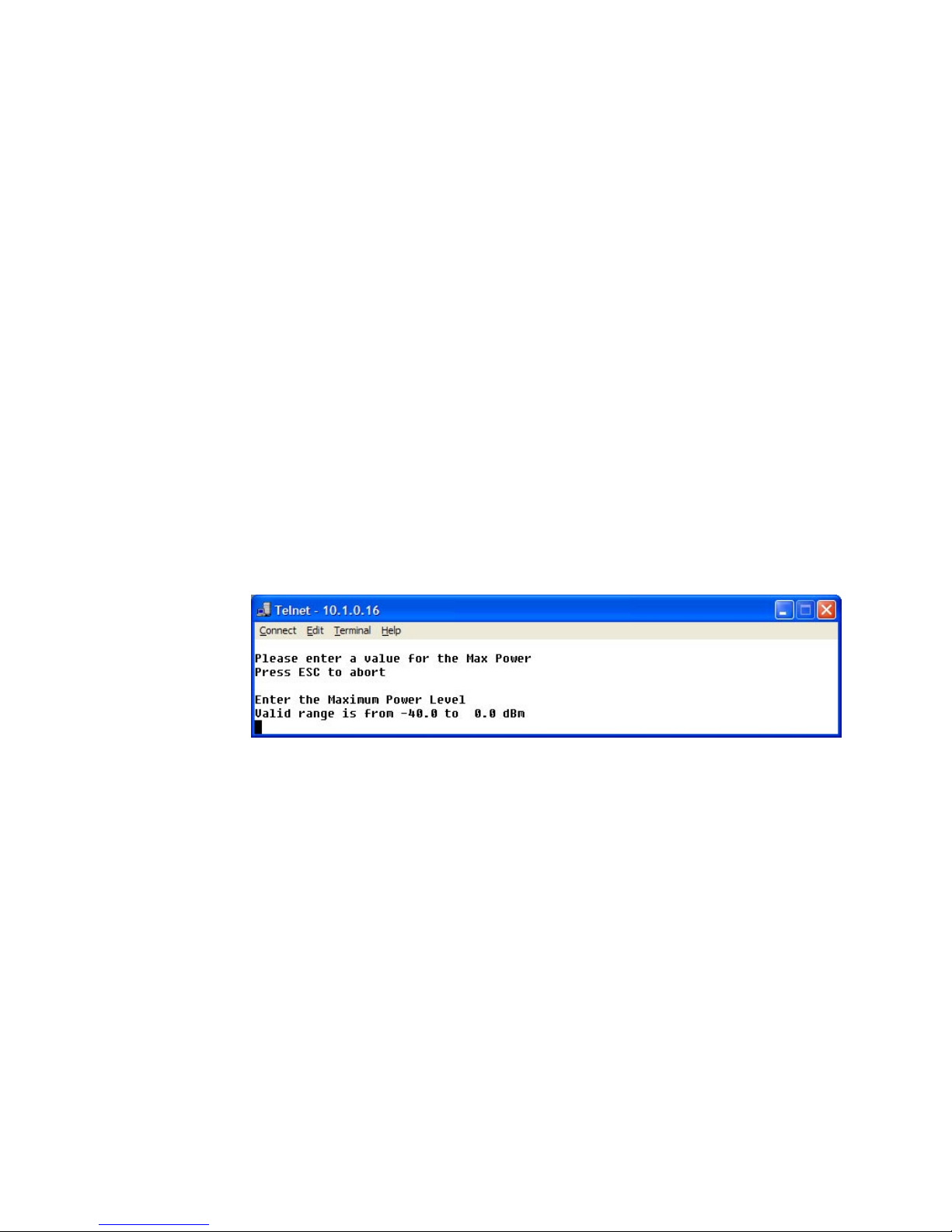
Vipersat Configuration
3-40 Vipersat CDM-570/570L User Guide
Calibrated Data Rate
This menu item is for information only and displays the Calibrated Data Rate
in Kbps for the target CDM-570/570L.
There is a proportional relationship between data rate and power level; as the
data rate increases, there is a corresponding increase in transmit power level,
and vice versa.
Nominal Power Level
This menu item is for information only and displays the Nominal Power Level
in dB for the modulator. This power level will vary as the data rate varies.
Max Power
The commissioning of a satellite terminal must comply with the calculated link
budget that is conducted before terminal installation. Using these calculations,
the maximum transmit power level permitted for the modulator(s) based on
link/satellite parameters can be configured. This is the value set by the Max
Power command in the DPC Configuration menu. Enter A at the command
prompt to display the Max Power dialog shown in figure 3-53.
Figure 3-53
Maximum Power Level prompt (CDM-570L)
If more than one modulator is used at this location, that must also be taken into
consideration and applied to this value set point. The value entered sets the
maximum power level allowed by all SCPC modulators.
Min Power
The Minimum Power level setting corresponds to the lowest transmit power
level permitted based on link/satellite parameters. Min Power typically can be
set to the lowest default value (-25.0 dBm for the CDM-570, -40.0 dBm for the
CDM-570L). There is generally no problem in allowing the modulator(s) to
reduce power levels when link conditions improve. Enter I at the command
prompt to display the Min Power dialog shown in figure 3-54.
Page 75

Chapter 3 - Using the Command Line Interface (CLI) 3-41
Vipersat Configuration
Figure 3-54
Minimum Power Level prompt (CDM-570L)
The value entered sets the minimum power level allowed by all SCPC modulators.
Max Step Down Power
The Maximum Step Down Power value sets the largest step reduction in transmit power permitted when the DPC is adjusting the power downward to achieve
the target set point. The default value for this parameter is 3 dB.
Enter D at the command prompt to display the Max Step Down Power dialog
shown in figure 3-55.
Figure 3-55
Maximum Step Down Power prompt
Max Step Up Power
The Maximum Step Up Power value sets the largest step increase in transmit
power permitted when the DPC is adjusting the power upward to achieve the
target set point. The default value for this parameter is 3 dB.
Enter U at the command prompt to display the Max Step Up Power dialog
shown in figure 3-56.
Figure 3-56
Maximum Step Up Power prompt
Page 76

Vipersat Configuration
3-42 Vipersat CDM-570/570L User Guide
Target EbNo
The Target EbNo is the desired operating receive level for closed loop servo
control. This is the value used by the receiving CDM-570/570L for comparison
with the actual received Eb/No. This information is sent back to the transmitting
terminal for output power level adjustment as necessary.
Enter T at the command prompt in the DPC Configuration screen to display
the Target EbNo dialog shown in figure 3-57. The default value for this parameter is 10 dB.
Figure 3-57
Target EbNo prompt
Target Ra nge
The Target Range command sets the range on either side of the Target EbNo
value, plus or minus, where the received level at the demodulator is acceptable
and no adjustment to the output power of the transmitting terminal is necessary.
Enter R at the command prompt in the DPC Configuration screen to display
the Target Range dialog shown in figure 3-58. The default value for this parameter is 0.2 dB.
Figure 3-58
Target Range prompt
Speed Up EbNo
Normally, the PLDM (Path Loss Data Multicast) is sent every 60 seconds from
each terminal in the network. If the received Eb/No level at the demodulator
drops below the Speed Up EbNo set value, the corresponding terminal
increases its PLDM send rate to every 15 seconds until the receive level is
greater than the set value. This provides a loop speed up to rapidly regain link
quality.
Page 77

Chapter 3 - Using the Command Line Interface (CLI) 3-43
Vipersat Configuration
Enter Q at the command prompt in the DPC Configuration screen to display
the Speed Up EbNo dialog shown in figure 3-59. The default value for this
parameter is 5 dB.
Figure 3-59
Speed Up EbNo prompt
Target DPC Address
The Target DPC Address identifies the modem that is transmitting to this
CDM-570/570L, and will be receiving the PLDM messages that provide the
current Eb/No value for this CDM-570/570L. Typically, all Remotes will specify the Hub modem that is supplying the TDM outbound. The Outbound IP
address is sent out to all STDMA Remotes via the Burst Map, and the DPC
Target for these Remotes is automatically mapped to that address. When operating in a dedicated SCPC mode, the Remote’s Target DPC Address is configured
manually with this command.
Enter 1 at the command prompt to display the Target DPC Address dialog
shown in figure 3-60.
Figure 3-60
Target DPC Address prompt
The STDMA Burst Controller is not permitted to specify a DPC Target because
the demodulator is receiving multiple bursts very rapidly from all Remotes in
the group and is unable to utilize DPC to control the transmit power of the
remote modems.
Set Home State Parameters
A CDM-570/570L’s Home State are those parameters which the CDM-570/
570L will return to when it is power cycled or reset. Enter H at the command
Page 78

Vipersat Configuration
3-44 Vipersat CDM-570/570L User Guide
prompt in the Vipersat Configuration screen to display the Home State
Configuration screen shown in figure 3-61.
The parameters entered using this menu define the settings the target CDM-570/
570L will go to when it returns to its Home State, either as the result of a
command by the VMS, or as it comes back on line from a reset or a power
cycle. A CDM-570/570L’s Home State settings are typically selected so that it
goes to a configuration which is optimum for its function in the network.
Figure 3-61
Home State Configuration screen
Note that each of these Transmit and Receive parameters are the same as found
in the Tx Configuration and the Rx Configuration screens that are in the
Satellite Modem Configuration menu.
Set Current Configuration as Home State
This command sets the CDM-570/570L’s current configuration as its Home
State settings. Assuming the modem has been properly configured using the
Satellite Modem Configuration menu (Tx and Rx parameters) and the
Feature Configuration menu (Vipersat STDMA setting), these parameter
values will be copied into the Home State configuration. Rather than entering
each of these values individually, this command can be used as a shortcut for
establishing the Home State settings.
Enter W at the command prompt in the Home State Configuration screen to
execute this command. Once saved, the modem will be configured with the
Home State settings at boot time and when manually reset with the Force
Modem to Home State command.
Page 79

Chapter 3 - Using the Command Line Interface (CLI) 3-45
Vipersat Configuration
Tip: This command is useful when a CDM-570/570L’s initial set up is
completed and the unit is functioning as desired in a network.
Force Modem to Home State
If at any time it is desired to have a CDM-570/570L return to its Home State,
this command (enter Y) can be executed. The Home State parameter values are
“forced” into the Base Modem configuration so that they match. The Base
Modem parameters will be updated to reflect any modifications that have been
made from this menu.
A warning message is displayed as shown in figure 3-62, requiring the
command to be confirmed before it is executed.
Figure 3-62
Force Modem to Home State warning
STDMA State
This command (enter T) toggles the setting of STDMA in the target CDM-570/
570L’s home state between Enabled and Disabled. This is the same feature that
is set from the Feature Configuration menu screen shown in figure 3-3.
Transmit Frequency
Enter A at the command prompt to use the dialog shown in figure 3-63 to set the
Transmit Frequency for the target CDM-570/570L’s home state.
Figure 3-63
Transmit Frequency prompt
Note that this screen dialog example displays the frequency range for the CDM570L L-Band modem. For the CDM-570, the range displayed will be either 50
to 90 MHz or 100 to 180 MHz.
Transmit Data Rate
Enter B at the command prompt to use the dialog shown in figure 3-64 to set the
Transmit Data Rate for the target CDM-570/570L’s home state.
Page 80

Vipersat Configuration
3-46 Vipersat CDM-570/570L User Guide
Figure 3-64
Transmit Data Rate prompt
Note that the valid range for this parameter will vary depending on the modulation type, coding rate, and FAST feature data rate.
Transmit FEC Type
Enter C at the command prompt to use the dialog shown in Figure 3-65 to enter
the FEC Coding Type for the CDM-570/570L’s home state. Turbo must be
selected when operating in Vipersat mode.
Figure 3-65
Transmit FEC Type prompt
Transmit Coding Rate
Enter D at the command prompt to use the dialog shown in figure 3-66 to set the
Transmit Coding Rate for the target CDM-570/570L’s home state.
Note that Coding Rates 3 (1/2), 4 (2/3), and 8 (1/1) are not valid selections when
operating in Vipersat mode with Turbo Product Coding.
Figure 3-66
Transmit Coding Rate prompt
Page 81

Chapter 3 - Using the Command Line Interface (CLI) 3-47
Vipersat Configuration
Transmit Modulation Type
Entering E at the command prompt to use the dialog shown in figure 3-67 to set
the Transmit Modulation Type for the target CDM-570/570L’s home state.
Figure 3-67
Transmit Modulation Type prompt
Transmit Power Level
Enter F at the command prompt to use the dialog shown in Figure 3-68 to set
the Transmit Power Level for the target CDM-570/570L’s home state.
Figure 3-68
Transmit Power Level prompt
Transmit Enable
The modem transmitter can be Enabled or Disabled with this command. Enter G
at the command prompt to toggle the Transmit Enable for the target
CDM-570/570L’s home state between On and Off.
Receive Frequency
Enter M at the command prompt to use the dialog shown in Figure 3-69 to set
the Receive Frequency for the target CDM-570/570L’s home state.
Figure 3-69
Receive Frequency prompt
Page 82

Vipersat Configuration
3-48 Vipersat CDM-570/570L User Guide
Note that this screen dialog example displays the frequency range for the CDM570L L-Band modem. For the CDM-570, the range displayed will be either 50
to 90 MHz or 100 to 180 MHz.
Receive Data Rate
Enter N at the command prompt to use the dialog shown in Figure 3-70 to set
the Receive Data Rate for the target CDM-570/570L’s home state.
Figure 3-70
Receive Data Rate prompt
Note that the valid range for this parameter will vary depending on the modulation type, coding rate, and FAST feature data rate.
Receive FEC Type
Enter O at the command prompt to use the dialog shown in figure 3-71 to set the
Receive FEC Type for the target CDM-570/570L’s home state. Turbo must be
selected when operating in Vipersat mode.
Figure 3-71
Receive FEC Type prompt
Receive Coding Rate
Enter P at the command prompt to use the dialog shown in Figure 3-72 to set
the Receive Coding Rate for the target CDM-570/570L’s home state.
Page 83

Chapter 3 - Using the Command Line Interface (CLI) 3-49
Vipersat Configuration
Figure 3-72
Receive Coding Rate prompt
Note that Coding Rates 3 (1/2), 4 (2/3), and 8 (1/1) are not valid selections when
operating in Vipersat mode with Turbo Product Coding.
Receive Modulation Type
Enter Q at the command prompt to use the dialog shown in Figure 3-73 to set
the Receive Modulation Type for the target CDM-570/570L’s home state.
Figure 3-73
Receive Modulation Type prompt
Vipersat Summary
The Vipersat Summary screen can be viewed by entering D at the command
prompt in the Vipersat Configuration screen (figure 3-5).
Page 84

Vipersat Configuration
3-50 Vipersat CDM-570/570L User Guide
Figure 3-74
Vipersat Summary screen
The Node ID number that appears in this screen verifies that the unit is registered with the VMS and is active in the network. This number is automatically
assigned by the VMS.
The two frequency listings are for the modulator (0) and the demodulator (1) for
the CDM-570/570L. The IF values represent the Intermediate Frequency (Hz)
that this unit is currently using. The AF values represent Adjusted Frequency
(Hz), a translation of the IF that is used by the VMS for internal tracking of
switching commands.
The DPC target entry is the IP address of the modulator that is to receive the
DPC messages from this unit.
The Primary Heart Beat Interval represents the time period between the
communication check message that is sent from the primary Hub modem to the
VMS in an N:M redundancy configuration. This interval is specified in the
VMS.
Vipersat Migration
The Vipersat Migration command is used to set the compatibility mode for the
Hub Burst Controller when conducting a firmware upgrade on the associated
CDM-570/570L Remotes. Although this command appears in the menu for both
the Hub modem and the Remote modem, it only applies to STDMA Controllers
and TDM Outbound modems at the Hub.
Enter M at the command prompt in the Vipersat Configuration screen to
display the Vipersat Migration dialog shown in figure 3-75.
Page 85

Chapter 3 - Using the Command Line Interface (CLI) 3-51
Vipersat Configuration
Figure 3-75
Vipersat Migration prompt
Refer to Appendix D, Firmware Installation, in this document for additional
information on the use of this command.
Page 86

Vipersat Configuration
3-52 Vipersat CDM-570/570L User Guide
{ This Page is Intentionally Blank }
Page 87

Appendix A - Network Addressing A-1
A
PPENDIX
NETWORK ADDRESSING
This Appendix is an overview of network addressing and how it applies to
configuring the CDM-570/570L for use in Vipersat Networks. The subjects
covered are:
• OSI Model
• Binary Math
• IP Addressing
• Network Address Translation
• Subnets
• Network Segments
• Default Gateways
• MAC Addresses
Page 88

The OSI Reference Model
A-2 Vipersat CDM-570/570L User Guide
The OSI Reference Model
OSI is an acronym for Open Systems Interconnection. This is a network model
created by ISO (the International Standardization Organization.) The OSI model
is the basic standard which forms the basis for all networking protocols.
Figure A-1
The Seven OSI Protocol Layers
The OSI model defines the building blocks used to construct a working network
protocol as shown in Figure A-1. The blocks on the right show the individual
layers which make up the OSI model and the blocks on the left show the layer’s
functional grouping.
Each layer, as defined by the OSI model, is only aware of the layers directly
above and below it.
Layers 1 – 3
Layer 1 / Physical – Layer 1 defines the physical means by which actual bits
are sent and received. This layer, for example, is where connectors, cable
lengths, and signaling specifications are defined.
Layer 2 / Data Link – Layer 2 consist of two sub-layers:
• Logical Link Control (LLC) – The LLC packages bytes received from the
MAC into a format readable by the Network Layer above it.
• Media Access Control (MAC) – The MAC is concerned with obtaining
access to the network at an appropriate time; i.e., when no other machines
are communicating or when permission has been granted.
Together, these two sub-layer protocols are responsible for moving packets on
and off the network.
Page 89

Appendix A - Network Addressing A-3
The OSI Reference Model
Layer 3 / Network Layer – Layer 3 is responsible for routing packets through
multiple networks. The Layer 3 protocol operates without regard to the underlying protocols in use. For example, routers operate at Layer 3.
Page 90

Binary Math
A-4 Vipersat CDM-570/570L User Guide
Binary Math
Network devices communicate using BITS, where a bit is a single digit represented by a 1 or a 0, or by using BYTEs, where a byte is made up of eight bits in
any combination of 1’s or 0’s. A byte is also referred to as an octet.
Figure A-2
Bits and Bytes
An octet can be converted to or from binary using the technique shown in the
decimal conversion chart in Figure A-3. The conversion chart also shows the
decimal equivalent of the binary number.
Figure A-3
Binary to Decimal Conversion
Bits containing a 1 in Figure A-3 determine which decimal values should be
added. These decimal values, when added together, determine the decimal
equivalent for the binary number.
This is an example of changing a number expressed in binary (base 2) to its
decimal equivalent (base 10). The numeric value is the same, you have only
changed the numbering base (radix.) All digital processes are done in binary.
128 64 32 16 8 4 2 1
1
101 100 01 = 165
11 10 0 0 0 0 = 194
1111 11 11=255
128
32
4
1
_____
165
Page 91

Appendix A - Network Addressing A-5
Binary Math
The conversion to decimal is done whenever binary values need to be read or
entered by humans as their decimal equivalents.
Page 92

IP Addressing
A-6 Vipersat CDM-570/570L User Guide
IP Addressing
An IP (Internet Protocol) address is a unique set of numbers assigned to a device
on a network to uniquely identify that device (by its IP address).
An IP address is a unique number composed of four octets, with each octet
separated by a dot. This notation style is called dotted decimal notation.
Each IP address can be broken down into two parts, as shown in the example
below:
Example:
128.121.188.201
The first two octets are the network ID:
128.121
The second two octets are the host ID:
188.201
• Network ID - In this example, the 128.121 portion of the IP address
defines the network that a host belongs to, and is equivalent to a street
name in a mailing address.
• Host ID - The 188.201 portion of the IP address specifies a unique number
assigned to the host on the network, and is equivalent to a house number in
a mailing address.
IP Address Classes
IP addresses are assigned to classes according the schedule shown in
Figure A-4. IP address classes are assigned as follows:
Class A
• 1.x.x.x to 126.x.x.x (0 and 127 are reserved)
• 126 Class As exist
• Can have 16,777,214 hosts on each Class A
• 8-bit network number
• 24-bit node number
Class B
• 128.0.x.x to 191.254.x.x
• 16,384 Class Bs exist
• Can have 65,354 hosts on each Class B
• 16-bit network number
Page 93

Appendix A - Network Addressing A-7
IP Addressing
• 16-bit node number
Figure A-4
IP Address Classes A, B, C
Class C
• 192.0.1.x to 223.255.254.x
• 2,097,152 Class Cs exist
• Can have 254 hosts on each Class C
• 24-bit network number
• 8-bit node number
Class D
• 224.0.0.0 to 239.255.255.255
• Reserved for Multicast (messages sent to many hosts).
Class E
• 240.0.0.0 to 255.255.255.255
• Reserved for experimental use and limited broadcast
CLASS A
CLASS B
CLASS C
2,097,152
16,384
126
Networks
Available
192-223.x.y.z
128-191.x.y.z
1-126.x.y.z
1
st
Octet
Decimal Range
254110 Class C
65,53410Class B
16,777,2140Class A
Hosts
Available
HighOrder-Bits
Address
Class
2,097,152
16,384
126
Networks
Available
192-223.x.y.z
128-191.x.y.z
1-126.x.y.z
1
st
Octet
Decimal Range
254110 Class C
65,53410Class B
16,777,2140Class A
Hosts
Available
HighOrder-Bits
Address
Class
Page 94

IP Addressing
A-8 Vipersat CDM-570/570L User Guide
Private Network IP Addresses
RFC 1918 defines blocks of addresses for use on private networks:
• 10.0.0.0 – 10.255.255.255
• 172.16.0.0 – 172.31.255.255
• 192.168.0.0 – 192.168.255.255
Network Address Translation (NAT)
Private networks can only connect to the public Internet by using a Network
Address Translation (NAT) device (a router, for example) or a proxy server
which has been assigned a public IP address. These network devices use a
public IP address to request information from the Internet on behalf of the
private IP addressed devices on the associated private network.
Figure A-5
NAT Router Example
This use of private addresses helps to conserve public IP addresses.
Subnets
Subnets can be defined as the further segmentation of the InterNIC assigned
Network ID IP address. The amount and type of subnetting performed by the
organization is determined by the network layout.
In the process of subnetting, bits are borrowed from the host ID portion of an IP
address and are then given to the network ID. Then a “Subnet Mask” gets
assigned to the host along with the IP address.
Ethernet
Host 1
Host 2
NAT Router
Internet
192.168.0.2
192.168.0.3
192.168.0.1 Public IP
Page 95
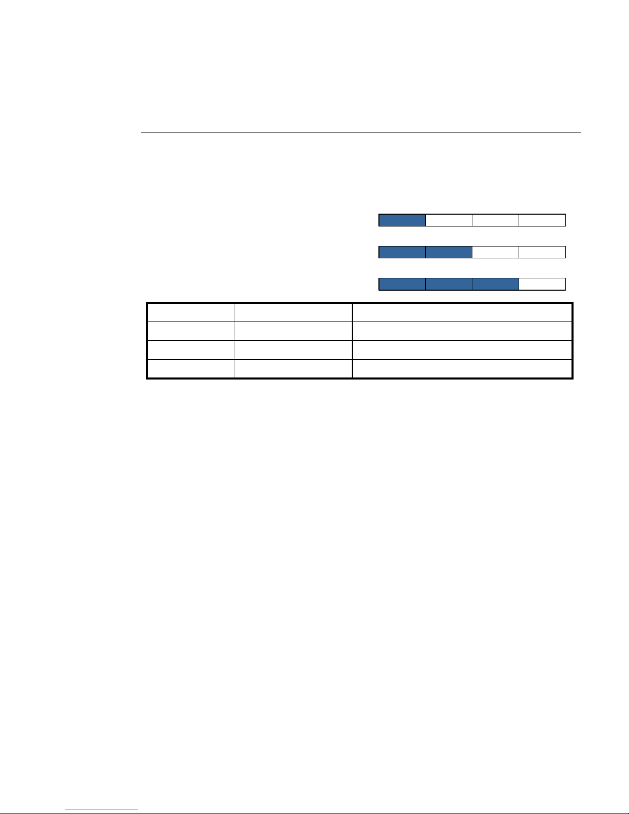
Appendix A - Network Addressing A-9
IP Addressing
Subnetting is required if the network is segmented.
Subnet Mask
The Subnet Mask is used by the host to determine if a destination IP address is
on the local or on a remote network segment. The table in Figure A-6 shows the
default subnet mask used for each class of IP address.
Figure A-6
Default Subnet Masks for IP Classes
The IP address and subnet mask work with each other to identify a network
element or device. The subnet mask, like an IP address, contains 4 octets separated by a dot (.) and looks similar to an IP address.
The subnet mask determines what bits in the IP address are being used to determine the network ID by using the Boolean math operator and in a process
called anding. Anding compares each bit value in the IP address with the bit
value in the subnet mask. The result of the anding process determines which
subnet the IP address is on. The Boolean and operator works as follows:
0 and 0 = 0
1 and 0 = 0
1 and 1 = 1
The table shown in Figure A-7 shows the anding of two binary values and the
corresponding decimal equivalents for each of the values.
11111111.11111111.11111111.00000000255.255.255.0Class C
11111111.11111111.00000000.00000000255.255.0.0Class B
11111111.00000000.00000000.00000000255.0.0.0Class A
Mask Binary ValueMask Decimal ValueAddress Class
11111111.11111111.11111111.00000000255.255.255.0Class C
11111111.11111111.00000000.00000000255.255.0.0Class B
11111111.00000000.00000000.00000000255.0.0.0Class A
Mask Binary ValueMask Decimal ValueAddress Class
CLASS A
CLASS B
CLASS C
Page 96

IP Addressing
A-10 Vipersat CDM-570/570L User Guide
Figure A-7
ANDing an IP address and a subnet mask
A calculator, available from SolarWinds, performs these IP and subnet mask
calculations and can be found at:
http://support.solarwinds.net/updates/SelectProgramFree.cfm
Network Segments
A “Network Segment” is a portion of a network that is bordered by two router
interfaces as shown in Figure A-8.
Figure A-8
Network Segments
Each network segment must either be on a different network or a different
subnet. For example, if you have a single IP address available, you can change
the default mask from 255.255.255.0 to 255.255.255.192. The resulting calculation yields four subnets:
• 192.168.100.0
• 192.168.100.64
• 192.168.100.128
• 192.168.100.192
ANDing Result
Subnet Mask
IP Address
11000000.10101000.00000010.00000000192.168.2.0
11111111.11111111.11111111.00000000255.255.255.0
11000000.10101000.00000010.01000010192.168.2.66
Binary Values
Dotted Decimal
Address
ANDing Result
Subnet Mask
IP Address
11000000.10101000.00000010.00000000192.168.2.0
11111111.11111111.11111111.00000000255.255.255.0
11000000.10101000.00000010.01000010192.168.2.66
Binary Values
Dotted Decimal
Address
Page 97

Appendix A - Network Addressing A-11
IP Addressing
Each of the four subnets can, in turn, support 64 members.
The example subnet used above yielded 4 subnets, but you can use a different
mask to meet the specific requirements of your network.
Default Gateways
A default gateway is a network device, usually a router, that is responsible for
routing data packets out of the local network segment.
The address of the gateway is entered into the devices on the local network,
providing them with a location to send data that is destined for another segment.
Figure A-9
Router as Default Gateway
MAC Addresses
A MAC address is a physical hardware address that gets assigned to the interface of a networking device. This address is typically created and burned into a
device’s ROM during the manufacturing process. MAC addresses are unique to
the device and are not typically user-assignable.
The MAC address is used for Layer 2 (Data Link) communications between
networking devices, and consists of 12 alpha-numeric characters as shown in
the example below:
Example: 00-3f-bf-00-01-45
Page 98
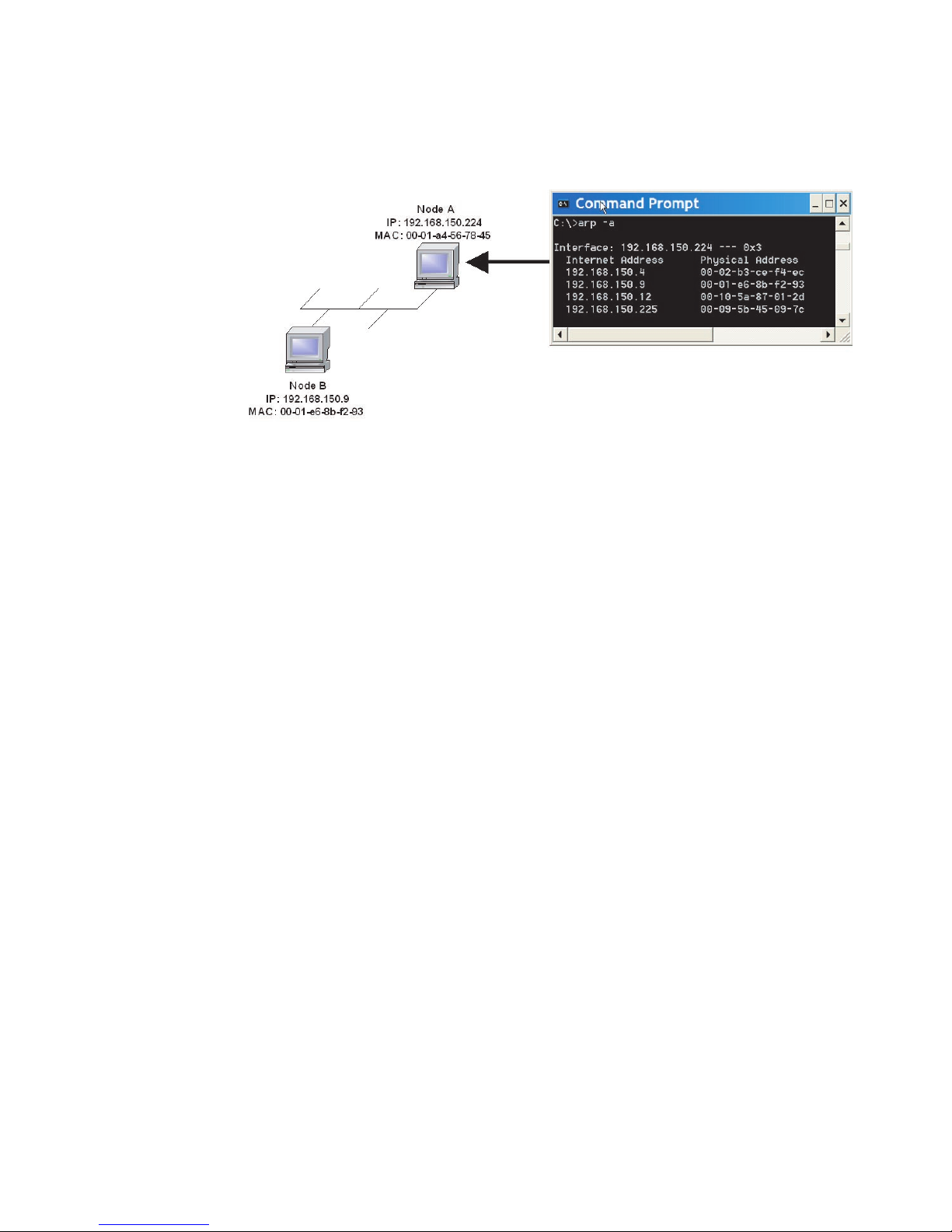
IP Addressing
A-12 Vipersat CDM-570/570L User Guide
• The first six characters are issued to the organization.
• The second six characters are assigned to the hardware interface by
manufacturing.
Figure A-10
Network Node MAC Addresses
Page 99

Appendix B - Automatic Switching B-1
A
PPENDIX
AUTOMATIC SWITCHING
General
Automatic switching is a feature of VMS which allows dynamically changing
network configuration in response to changes in either traffic type (application
switching) or network traffic loads (load switching.)
The following discussions apply to the Vipersat CDM-570/570L, CDD-564L,
and CDM-600. Throughout the following discussion, these units are referred to
as modem/routers.
Bandwidth Allocation and Load Switching
Load Switching is the mechanism by which the Vipersat network switches a
remote terminal from STDMA to SCPC mode based on traffic levels at the
remote. There are two components of load switching in a Vipersat system: VMS
(network management) and CDM (Comtech Data Modem). The VMS component receives switch requests from the CDM, and based on policy settings and
available resources, either grants or denies the request. Within the CDM component, load switching is managed at either the Hub or the Remote, based on the
current mode of operation. When a remote is in STDMA mode, load switching
for that remote is managed by the Hub STDMA controller. After a Remote has
been switched to SCPC mode it manages its own switching (or Step Up / Step
Down) requests.
The basic concept for all load switching is that a running average of current
utilization is maintained, and when that utilization exceeds a pre-set threshold, a
switch is initiated. The data rate for the switch is computed by determining the
current bandwidth requirement of the remote and adding some percentage of
Page 100

Load Switching
B-2 Vipersat CDM-570/570L User Guide
excess margin. The main difference between switching from STDMA to SCPC
and adjusting within SCPC is that in STDMA mode, the current available bandwidth is constantly changing while in SCPC mode it is constant between
switches. Furthermore, switches from STDMA to SCPC mode are always
caused by the traffic level exceeding the switch threshold. Within SCPC mode,
switches can be caused by traffic exceeding an upper threshold or dropping
below a lower threshold. However, in both cases the new data rate is based on
the actual traffic requirements adjusted up by the margin percentage. Also,
based on policies set in the VMS, if a remote requests less than some threshold
amount of bandwidth, the remote in put back into STDMA mode.
Note: If the Hub STDMA mode is GIR (Guaranteed Information Rate) or
Entry Channel, normal load switching is automatically disabled.
In GIR mode, the remote is switched to SCPC as soon as the GIR
threshold is reached, if there is a switch rate defined. In Entry
Channel mode, the remote is switched to SCPC as soon as the
hub receives the first transmission from the remote.
Load Switching
The next sections describe the principles behind Load Switching and Rate
Adjustment (Step Up / Step Down).
Bandwidth Allocation and Load Switching by the STDMA
Controller:
As part of normal STDMA processing, the hub monitors the traffic levels from
each of the remotes for which it is allocating bandwidth. This is done using the
STDMA ACK management message (Table 1) which is transmitted at the
beginning of each burst from the remote. The STDMA ACK contains two
metrics that are used by the hub:
1. The number of bytes received for transmission (Queued Bytes) since the last
cycle.
2. The number of bytes currently waiting to be transmitted (Bytes In Queue).
These metrics are used by the hub for 3 purposes:
1. Determine the amount of STDMA bandwidth (slot size) to allocate in the
next cycle.
2. Provide statistics of the amount of activity at each remote (Average Bytes
Received).
NOTE
 Loading...