

Page 1

UT-4579
X-Band Up Converter
Installation and Operation Manual
Part Number MN/UT4579.IOM
Rev. 0
Page 2

Page 3

Errata A
Comtech EF Data Documentation Update
Subject:
Date:
Document:
Part Number:
Collating Instructions:
Comments:
The following changes provide updated information for Table 1. This information will be
incorporated into the next revision.
Changes to Table 1. UT4579 X-Band Up Converter Specifications
January 31, 2003
UT4579 X-Band Up Converter, Installation and Operation Manual,
Rev. 0, dated Nov. 20, 2002
MN/UT4579.EA0.DOC
Attach this page to page 3.
Change Specifics:
IF Input
Range
Transfer
IF Bandwidth
Note 1. Please contact factory with specific requirements.
Ripple
Table 1. UT-4579 X-Band Up Converter Specifications
52 to 88 or 104 to 176 MHz, optional 50 to 90 MHz or
100 to 180 MHz, see Note 1
± 0.25 dB (± 18 MHz), optional ± 20 MHz, see N ote 1
0.75 dB (± 36 MHz), optional ± 40 M Hz, see N ote 1
36 or 72 MHz, optional 40 or 80 MHz, se e Note 1
Filename: T_ERRATA 1
Page 4

Page 5

Comtech EF Data is an ISO 9001
Registered Company.
UT-4579
X-Band Up Converter
Installation and Operation Manual
Part Number MN/UT4579.IOM
Rev. 0
Nov. 20, 2003
Copyright © Comtech EF Data, 2001. All rights reserved. Printed in the USA.
Comtech EF Data, 2114 West 7th Street, Tempe, Arizona 85281 USA, (480) 333-2200, FAX: (480) 333-2161.
Page 6

UT4579 X-Band Up Converter MN/UT4579.IOM
Preface Rev. 0
CUSTOMER SUPPORT
Contact the Comtech EF Data Customer Support Department for:
Product support or training
Information on upgrading or returning a product
Reporting comments or suggestions concerning manuals
A Customer Support representative may be reached at:
Comtech EF Data
Attention: Customer Support Department
2114 West 7th Street
Tempe, Arizona 85281 USA
480.333.2200 (Main Comtech EF Data Number)
480.333.4357 (Customer Support Desk)
480.333.2161 FAX
or, E-Mail can be sent to the Customer Support Department at:
service@comtechefdata.com
Contact us via the web at www.comtechefdata.com.
To return a Comtech EF Data product (in-warranty and out-of-warranty) for repair or
replacement:
1. Request a Return Material Authorization (RMA) number from the
Comtech EF Data Customer Support Department.
2. Be prepared to supply the Customer Support representative with the model
number, serial number, and a description of the problem.
3. To ensure that the product is not damaged during shipping, pack the
product in its original shipping carton/packaging.
4. Ship the product back to Comtech EF Data. (Shipping charges should be
prepaid.)
For more information regarding the warranty policies, see Warranty Policy, p. xii.
ii
Page 7

Table of Contents
Customer Support.........................................................................................................................ii
TABLE OF CONTENTS.................................................................................................III
FIGURES......................................................................................................................VII
TABLES.......................................................................................................................VIII
About this Manual ....................................................................................................................... ix
Conventions and References.......................................................................................................ix
Metric Conversion .......................................................................................................................ix
Recommended Standard Designations ......................................................................................ix
Trademarks..................................................................................................................................ix
EMC Compliance..........................................................................................................................x
Federal Communications Commission (FCC) ........................................................................... x
Safety Compliance .......................................................................................................................xi
EN 60950....................................................................................................................................... xi
Warranty Policy..........................................................................................................................xii
CHAPTER 1. INTRODUCTION....................................................................................1
1.1 Overview..................................................................................................................................1
1.2 Functional Description........................................................................................................... 1
1.3 Physical Configuration...........................................................................................................3
1.3.1 Front Panel Display............................................................................................................ 4
1.3.2 Front Panel Test Point Samples ......................................................................................... 4
1.3.3 Prime Power Switch........................................................................................................... 4
1.4 Specifications........................................................................................................................... 5
1.5 Dimensional Envelope (UT-4579).......................................................................................... 7
iii
Page 8

UT4579 X-Band Up Converter MN/UT4579.IOM
Preface Rev. 0
CHAPTER 2. INSTALLATION.....................................................................................9
2.1 Unpacking and Inspection...................................................................................................... 9
2.2 Rack Mount Installation.........................................................................................................9
2.3 Prime Power Connection......................................................................................................10
2.4 Cable Connections ................................................................................................................ 10
2.4.1 Rear Panel Connections ................................................................................................... 10
2.4.2 EIA-485/EIA-232C Interface (COM 1), Connector J1.................................................... 11
2.4.3 High Speed Bus (HSB), Connector J3............................................................................. 12
2.4.4 Summary Fault Output (RELAY), Connector P1............................................................ 12
2.4.5 Cable Connections For Non-Redundant System Operation ............................................ 13
2.4.6 Cable Connections For Redundant System Operation..................................................... 13
CHAPTER 3. SYSTEM OPERATION........................................................................15
3.1 Overview................................................................................................................................15
3.2 Switching Power ON............................................................................................................. 17
3.3 Operation............................................................................................................................... 17
3.3.1 Converter Commands ...................................................................................................... 25
3.3.2 Configuration Functions Menu........................................................................................ 26
3.3.3 Pre-select Function Menu ................................................................................................ 26
3.3.4 Monitor Status Function Menu ........................................................................................ 27
3.3.5 Current Faults Function Menu......................................................................................... 27
3.3.6 Stored Faults .................................................................................................................... 28
3.3.7 Utility Function Menu...................................................................................................... 29
APPENDIX A. REDUNDANT SYSTEM OPERATION...............................................31
A.1 Overview............................................................................................................................... 31
A.2 Backup Converter................................................................................................................ 32
A.2.1 High Speed Bus (HSB) ................................................................................................... 32
A.2.2 Detachable Modules........................................................................................................ 32
A.3 Redundant Configurations.................................................................................................. 33
A.4 Redundant System Configuration......................................................................................39
A.4.1 Initial Configuration........................................................................................................ 39
A.4.2 Automatic Configuration Verification ............................................................................ 40
A.4.3 Manual Configuration/Verification................................................................................. 42
A.4.4 Offset Adjustment........................................................................................................... 44
iv
Page 9

UT4579 X-Band Up Converter MN/UT4579.IOM
Preface Rev. 0
A.4.5 Redundancy Systems - Converter Removal.................................................................... 44
APPENDIX B. REMOTE CONTROL..........................................................................47
B.1 Remote Control Overview................................................................................................... 47
B.2 Protocol ................................................................................................................................. 48
B.2.1 Transmission Mode......................................................................................................... 48
B.2.2 Baud Rate ........................................................................................................................ 48
B.2.3 Format ............................................................................................................................. 48
B.2.4 Character Set ................................................................................................................... 48
B.2.5 Response Timeout........................................................................................................... 48
B.2.6 Bus Inactivity Requirement............................................................................................. 48
B.3 Access Methods..................................................................................................................... 49
B.3.1 Direct Access................................................................................................................... 49
B.3.2 Indirect Access ................................................................................................................ 49
B.4 Addresses...............................................................................................................................50
B.4.1 Physical Address ............................................................................................................. 50
B.4.2 Virtual Address ............................................................................................................... 50
B.5 Message Structure................................................................................................................ 51
B.5.1 Start Character................................................................................................................. 51
B.5.2 Device Address ............................................................................................................... 51
B.5.3 Command ........................................................................................................................ 51
B.5.4 Confirmation Response................................................................................................... 51
B.5.5 Error Response ................................................................................................................ 52
B.5.6 End Of Message .............................................................................................................. 52
B.6 Command / Response Pairs................................................................................................. 53
B.6.1 Utility Commands ........................................................................................................... 53
B.6.2 Configuration Commands ............................................................................................... 56
B.6.3 Modes.............................................................................................................................. 59
B.6.4 Status Commands............................................................................................................ 61
B.6.5 Stored Alarm ................................................................................................................... 65
B.7 Error Processing................................................................................................................... 67
B.7.1 General Errors ................................................................................................................. 67
B.7.2 Configuration Errors ....................................................................................................... 67
B.7.3 Mode Errors..................................................................................................................... 67
B.7.4 Time-Outs........................................................................................................................ 67
B.8 Converter Remote Command Summary ........................................................................... 68
APPENDIX C. THEORY OF OPERATION.................................................................71
v
Page 10

UT4579 X-Band Up Converter MN/UT4579.IOM
Preface Rev. 0
C.1 Applications..........................................................................................................................71
C.2 RF Signal Conversion..........................................................................................................72
C.3 Monitor & Control............................................................................................................... 74
APPENDIX D. MAINTENANCE AND TROUBLESHOOTING...................................75
D.1 Overview............................................................................................................................... 75
D.2 Maintenance Testing............................................................................................................76
D.2.1 Test Point Samples.......................................................................................................... 76
D.2.2 Troubleshooting .............................................................................................................. 77
D.2.3 Converter Faults.............................................................................................................. 77
D.2.4 Converter I/O Modules ................................................................................................... 79
D.3 Spare...................................................................................................................................... 79
INDEX...........................................................................................................................81
vi
Page 11

UT4579 X-Band Up Converter MN/UT4579.IOM
Preface Rev. 0
Figures
Figure 1. Front Panel...................................................................................................................... 2
Figure 2. Rear Panel (shown with TSM Module).......................................................................... 2
Figure 3. Typical Converter Functional Block Diagram (Model UT-4579 shown)...................... 2
Figure 4. Physical Configuration - Up Converter.......................................................................... 3
Figure 5. Dimensional Envelope.................................................................................................... 7
Figure 6. Cable Interconnect Diagram......................................................................................... 13
Figure 7. Non-Redundant Converter Configuration .................................................................... 14
Figure 8. Non-Redundant Converter Configuration With Transmit Switch Module (TSM-XX)
Installed................................................................................................................................. 14
Figure 9. Front Panel.................................................................................................................... 15
Figure 10. Rear Panel (with TSM Module and optional REF Output)........................................ 15
Figure 11. Keypad........................................................................................................................ 17
Figure 12. Converter Operating Command Functions................................................................. 18
Figure 13. Configuration Menu Commands - Redundancy OFF. ............................................... 19
Figure 14. Configuration Menu Commands - Redundancy ON, Backup Unit Not Selected ...... 20
Figure 15. Configuration Menu Commands - Redundancy ON and Backup Unit Selected ...... 21
Figure 16. Pre-Select Menu Commands ...................................................................................... 22
Figure 17. Monitor Status Menu Commands............................................................................... 22
Figure 18. Current Faults Menu Commands................................................................................ 23
Figure 19. Stored Faults Menu Commands ................................................................................. 23
Figure 20. Utility Function Menu Commands............................................................................. 24
Figure 21. 1:1 Redundant Configuration - Single Source IF Input w/IOM and TSM-XX Installed
............................................................................................................................................... 34
Figure 22. 1:1 Redundant Configuration Diagram - Single Source IF Input w/IOM-XX and
TSM-XX Installed ................................................................................................................ 34
Figure 23. 1:1 Redundant Configuration Diagram - Single Source IF Input with IOM-XX and
TSEQM-XX Installed ........................................................................................................... 35
Figure 24. 1:1 Redundant Configuration - Dual Source IF Input................................................ 35
Figure 25 1:1 Redundant Configuration Diagram Dual Source IF Input with IOM-XX and
TSM-XX Installed. ............................................................................................................... 36
Figure 26. 1:N Redundant Configuration with IOM-XX and TSM-XX Installed ...................... 37
Figure 27. 1:N Redundant Configuration Diagram with IOM-XX and TSM-XX Installed ...... 38
Figure 28. 1:3 Front Panel Displays ............................................................................................ 39
Figure 29. 1:3 System in AUTO Redundant Mode ..................................................................... 40
Figure 30. Converter #1 Being Backed Up.................................................................................. 41
Figure 31. Converter #1 in MANUAL, Others in AUTO............................................................ 42
Figure 32. Forced BU of Converter #1 ........................................................................................ 43
Figure 33. Typical Converter Functional Block Diagram (Model UT-4579 shown).................. 73
Figure 34. Converter Signal and Interconnecting Cable Diagram (with TSM Switching
Module)................................................................................................................................. 76
vii
Page 12

UT4579 X-Band Up Converter MN/UT4579.IOM
Preface Rev. 0
Tables
Table 1. UT-4579 Up Converter Specifications ............................................................................ 5
Table 2. Rear Panel Connectors................................................................................................... 10
Table 3. J1, 2 Wire EIA-485 Interface Pin-Out........................................................................... 11
Table 4. J1, 4 Wire EIA-485 Interface Pin-Out........................................................................... 11
Table 5. J1, EIA-232C Interface Pin-Out .................................................................................... 11
Table 6. J3, High Speed Bus Connector Pin-Out......................................................................... 12
Table 7. P1, Summary Fault Connector Pin-Out ......................................................................... 12
Table 8. Operating Functions – Front Panel ................................................................................ 16
Table 9. 4579 Up Converter Configurations................................................................................ 33
Table 10. Remote Command Summary....................................................................................... 68
viii
Page 13

UT4579 X-Band Up Converter MN/UT4579.IOM
Preface Rev. 0
ABOUT THIS MANUAL
This manual provides installation and operation information for the Comtech EF Data
UT4579 X-Band Up Converter. This is a technical document intended for earth station
engineers, technicians, and operators responsible for the operation and maintenance of
the UT4579 X-Band Up Converter.
CONVENTIONS AND REFERENCES
CAUTIONS AND WARNINGS
Indicates information critical for proper equipment function.
IMPORTANT
CAUTION
Indicates a hazardous situation that, if not avoided, may result in minor or moderate
injury. CAUTION may also be used to indicate other unsafe practices or risks of
property damage.
Indicates a potentially hazardous situation that, if not avoided, could result in
WARNING
death or serious injury.
METRIC CONVERSION
Metric conversion information is located on the inside back cover of this manual. This
information is provided to assist the operator in cross-referencing English to Metric
conversions.
RECOMMENDED STANDARD DESIGNATIONS
Recommended Standard (RS) Designations have been superseded by the new designation
of the Electronic Industries Association (EIA). References to the old designations are
shown only when depicting actual text displayed on the screen of the unit (EIA-232, EIA485, etc.). All other references in the manual will be shown with the EIA designations
(EIA-232, EIA-485, etc.) only.
TRADEMARKS
All product names mentioned in this manual may be trademarks or registered trademarks
of their respective companies and are hereby acknowledged.
ix
Page 14

UT4579 X-Band Up Converter MN/UT4579.IOM
Preface Rev. 0
REPORTING COMMENTS OR SUGGESTIONS CONCERNING THIS MANUAL
Comments and suggestions regarding the content and design of this manual will be
appreciated. To submit comments, please contact the Comtech EF Data Customer
Support Department.
EMC COMPLIANCE
This is a Class A product. In a domestic environment, it may cause radio interference that
requires the user to take adequate protection measures.
EN55022 COMPLIANCE
This equipment meets the radio disturbance characteristic specifications for information
technology equipment as defined in EN55022.
EN50082-1 COMPLIANCE
This equipment meets the electromagnetic compatibility/generic immunity standard as
defined in EN50082-1.
FEDERAL COMMUNICATIONS COMMISSION (FCC)
This equipment has been tested and found to comply with the limits for a Class A digital
device, pursuant to Part 15 of the FCC rules. These limits are designed to provide
reasonable protection against harmful interference when the equipment is operated in a
commercial environment.
This equipment generates, uses, and can radiate radio frequency energy. If not installed
and used in accordance with the instruction manual, it may cause harmful interference to
radio communications. Operation of this equipment in a residential area is likely to cause
harmful interference; in which case, users are required to correct the interference at their
own expense.
Note: To ensure compliance, properly shielded cables for DATA I/O shall be used. More
specifically, these cables shall be shielded from end to end, ensuring a continuous shield.
x
Page 15

UT4579 X-Band Up Converter MN/UT4579.IOM
Preface Rev. 0
SAFETY COMPLIANCE
EN 60950
Applicable testing is routinely performed as a condition of manufacturing on all units to
ensure compliance with safety requirements of EN60950.
This equipment meets the Safety of Information Technology Equipment specification as
defined in EN60950.
LOW VOLTAGE DIRECTIVE (LVD)
The following information is applicable for the European Low Voltage Directive
(EN60950):
<HAR> Type of power cord required for use in the European Community.
!
CAUTION: Double-pole/Neutral Fusing.
ACHTUNG: Zweipolige bzw. Neutralleiter-Sicherung.
International Symbols:
Symbol Definition Symbol Definition
Alternating Current.
Fuse.
Protective Earth.
Chassis Ground.
Note: For additional symbols, refer to “Cautions” listed earlier in this preface.
xi
Page 16

UT4579 X-Band Up Converter MN/UT4579.IOM
Preface Rev. 0
WARRANTY POLICY
This Comtech EF Data product is warranted against defects in material and workmanship
for a period of 2 years from the date of shipment. During the warranty period, Comtech
EF Data will, at its option, repair or replace products that prove to be defective.
For equipment under warranty, the customer is responsible for freight to Comtech EF
Data and all related custom, taxes, tariffs, insurance, etc. Comtech EF Data is responsible
for the freight charges only for return of the equipment from the factory to the customer.
Comtech EF Data will return the equipment by the same method (i.e., Air, Express,
Surface) as the equipment was sent to Comtech EF Data.
LIMITATIONS OF WARRANTY
The foregoing warranty shall not apply to defects resulting from improper installation or
maintenance, abuse, unauthorized modification, or operation outside of environmental
specifications for the product, or, for damages that occur due to improper repackaging of
equipment for return to Comtech EF Data.
No other warranty is expressed or implied. Comtech EF Data specifically disclaims the
implied warranties of merchantability and fitness for particular purpose.
EXCLUSIVE REMEDIES
The remedies provided herein are the buyer's sole and exclusive remedies. Comtech EF
Data shall not be liable for any direct, indirect, special, incidental, or consequential
damages, whether based on contract, tort, or any other legal theory.
DISCLAIMER
Comtech EF Data has reviewed this manual thoroughly to provide an easy-to-use guide
to your equipment. All statements, technical information, and recommendations in this
manual and in any guides or related documents are believed reliable, but the accuracy and
completeness thereof are not guaranteed or warranted, and they are not intended to be,
nor should they be understood to be, representations or warranties concerning the
products described. Further, Comtech EF Data reserves the right to make changes in the
specifications of the products described in this manual at any time without notice and
without obligation to notify any person of such changes.
If you have any questions regarding the equipment or the information in this manual,
please contact the Comtech EF Data Customer Support Department.
xii
Page 17
Chapter 1. Introduction
UT-4579 Up
Converter
1.1 OVERVIEW
This manual provides instructions on the installation, operation and maintenance of the
UT-4579 Up Converters manufactured by Comtech EF Data Corp. Individual
specifications for each model are included in this section.
1.2 FUNCTIONAL DESCRIPTION
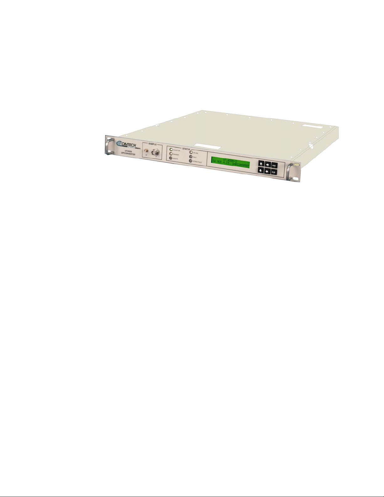
The UT-4579 Up Converter (Figure 1) is designed for use in communication systems, or
in satellite up-link data systems, for the transmission of SCPC, DAMA and TDMA
communication signals. The Up Converters also can be used in communications system
applications with full transponder HDTV and analog TV.
The converter is designed to be hard mounted in a standard 19-inch rack or cabinet, or to
be rack mounted using slide mechanisms provided with the converter to allow it to be
serviced without its removal from the rack. An internally mounted exhaust fan for
cooling is mounted on the rear of the chassis. An AC power connector, with an On/Off
switch, also is located on the rear on the chassis. A six-foot AC power cord is supplied
with the converter.
1
Page 18
UT4579 X-Band Up Converter MN/UT4579.IOM
Introduction Rev. 0
All operator controls, indicators and displays for local and remote operation are located
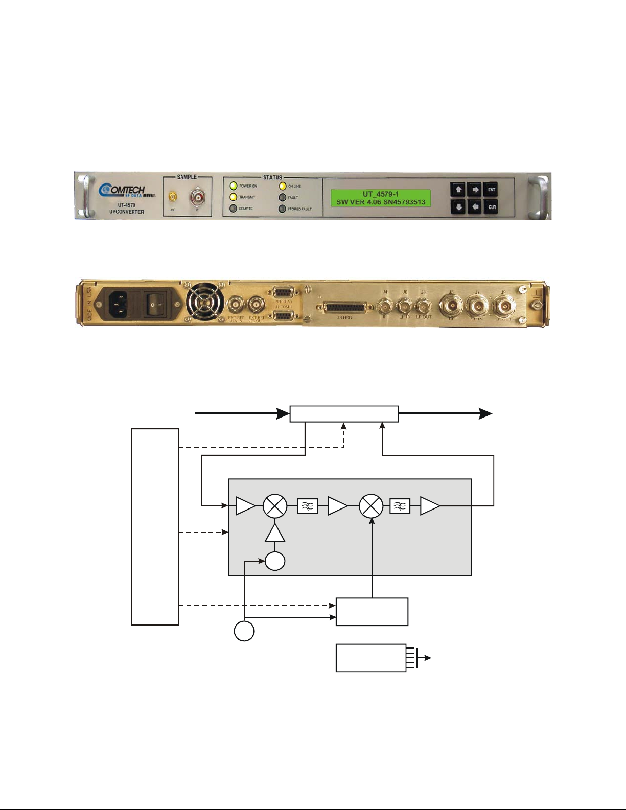
on the front panel of the converter. Connectors for the external interface connections
(Figure 2) are located on the rear of the converter chassis. A block diagram
(Figure 3) is provided to assist the technician in the operation of the converter.
Figure 1. Front Panel
MONITOR
&
CONTROL
Figure 2. Rear Panel (shown with TSM Module)
IF INPUT
(70 or 140 MHz)
I/O MODULE
OSC
SYNTHESIZER
OSC
(7900-8400 M Hz)
CONVERTER
SIGNAL PATH
RF OUTPUT
MODULE
5/10 MH z
REF. OSC.
POWER SUPPLY
Figure 3. Typical Converter Functional Block Diagram (Model UT-4579 shown)
2
Page 19
UT4579 X-Band Up Converter MN/UT4579.IOM
Introduction Rev. 0
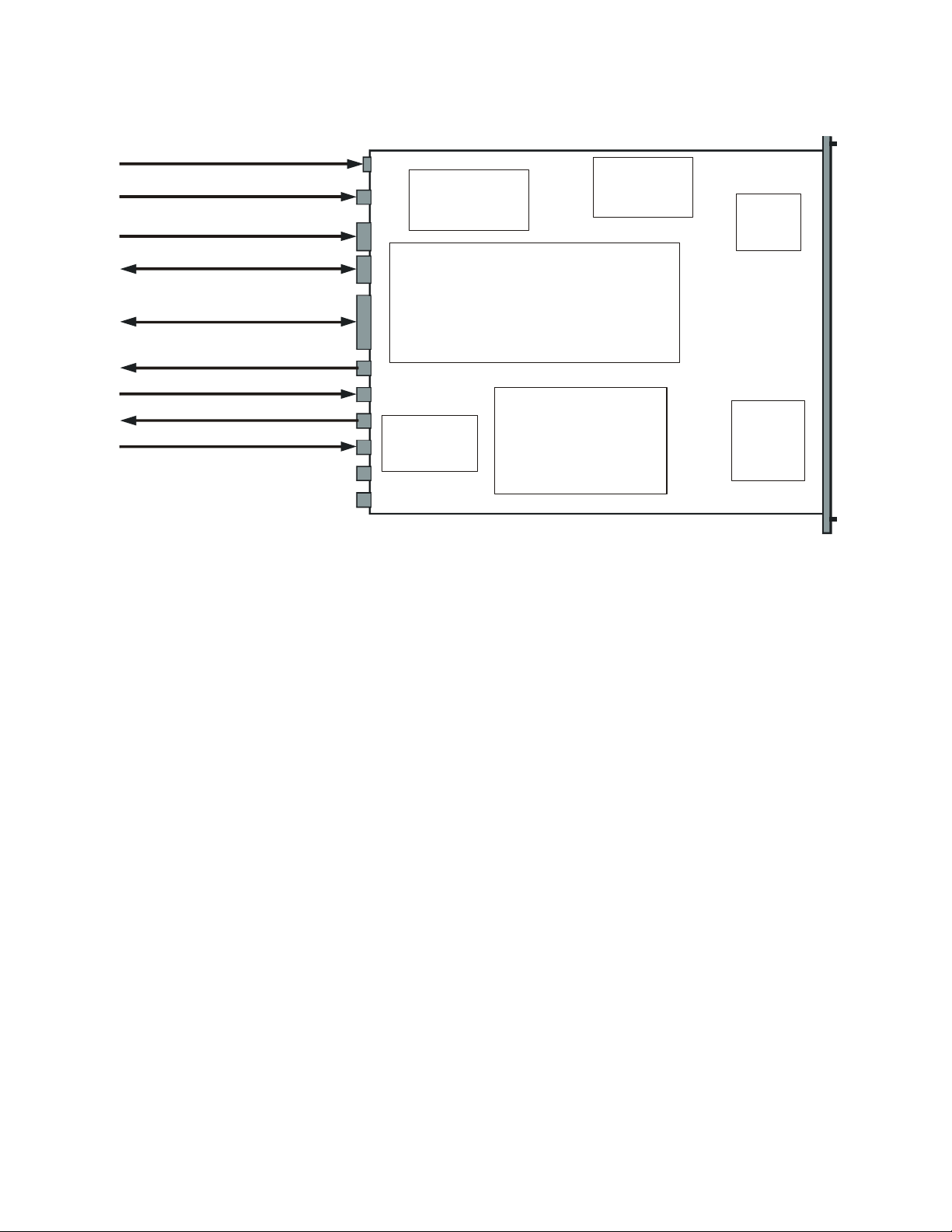
1.3 PHYSICAL CONFIGURATION
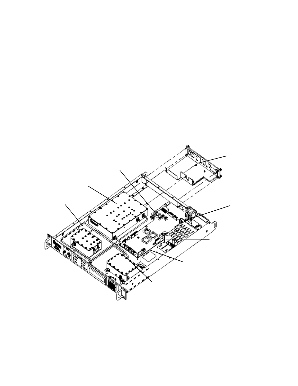
Figure 4 is a top view layout of a UT-4579 Up Converter chassis with the cover removed.
The major module assemblies shown in the layout are:
Signal Path Module.
Step Loop Module.
Monitor & Control Assembly.
TX I/O Switch Module (located in the right-hand space when facing the rear of the
chassis).
Reference Oscillator Assembly.
Sum Loop Module
Power Supply Assembly
Sum M odule
Signal
Path
Monitor
& Control
Board
Switch
M odule
Power Supply
Filter
M odule
Reference
Oscillator
Step
M odule
Figure 4. Physical Configuration - Up Converter
3
Page 20

UT4579 X-Band Up Converter MN/UT4579.IOM
Introduction Rev. 0
1.3.1 FRONT PANEL DISPLAY
The front panel display is a two line, 24-character, LCD display. Each configuration
function, or operating mode, is shown on the display when the operator enters a
command into the keypad on the front panel.
1.3.2 FRONT PANEL TEST POINT SAMPLES
Two test point connections are located on the front panel for monitoring the RF output
and the IF input. An SMA connector is provided for the RF output, and a BNC connector
is provided for the IF input. There is also an optional RF LO monitor available.
1.3.3 PRIME POWER SWITCH
The On/Off prime power switch is located on the rear of the chassis adjacent to the prime
power input connector. The power switch contains a filter and dual fuse. The dual fuse
is rated for 2 amps.
4
Page 21

UT4579 X-Band Up Converter MN/UT4579.IOM
Introduction Rev. 0
1.4 SPECIFICATIONS
Table 1. UT-4579 Up Converter Specifications
Characteristic Specification
Frequency Range
Frequency
Conversion
Step Size
Preset Channels
Stability Over Time
Stability Over Temp
IF Input
Noise Figure
Level
Range
Impedance
Return Loss
RF Output
Output Level
Intermodulation
Carrier Mute
Non–carrier Spurious
Carrier Spurious
AM to PM
Return Loss
Impedance
Transfer
Gain
Gain Adjust
Gain Stability
Ripple
Slope
External Reference
7900 to 8400 MHz
Dual, No Inversion
125 kHz standard, 1kHz optional
32 Frequencies and Gains
± 1 x 10
± 1 x 10
-9
/Day
-8
0 to 50°C
12 dB Maximum at 0 dB Attenuation
-35 dBm Typical
52 to 88 or 104 to 176 MHz
50 Ω or 75 Ω
23 dB Min. with IO Module or Switch Module
+13 dBm at 1 dB Compression
-46 dBc @ 0 dBm Output SCL
-70 dBc
-80 dBm
-65 dBc @ 0 dBm Output
0.1°/dB @ -5 dBm Out
20 dB Minimum with IO Module
18 dB Minimum with Switch Module
50 Ω
35 dB ± 2 dB
0 to 25 in 0.25 dB Steps
0.1 dB Steps Optional
± 0.25 dB/Day
± 0.25 dB (± 18MHz)
0.75 dB (± 36MHz)
0.05 dB/MHz
Input 5 or 10 MHz @ +3 dBm
Optional 10 MHz Rear Panel Reference Output
5
Page 22

UT4579 X-Band Up Converter MN/UT4579.IOM
Introduction Rev. 0
Characteristic Specification
Group Delay
Phase Noise
Linear Group Delay
Parabolic Delay
Group Delay Ripple
100 Hz
1 KHz
10 KHz
100 KHz
1 MHz
0.03 ns/MHz
0.01 ns/MHz
2
1 ns Peak-to-Peak
Limit (dBc/Hz)
-68
-79
-89
-100
-110
Typical (dBc/Hz)
-72
-82
-92
-102
-112
Remote Control (Rear Panel)
Indicators (Front Panel)
Power On
Mute
Remote
Reference
Stored Fault
Fault
Test Points (Front Panel)
RF Sample
IF Sample
Optional L.O. Sample
MTBF
Summary Alarm
Relay Closure
Power
Voltage
Frequency
Dissipation
COMM Port EIA-485 or EIA-232C
Green LED
Yellow LED
Yellow LED
Yellow LED
Red LED
Red LED
SMA, -20 dBc Nominal
BNC, -20 dBc Nominal
49,740 hrs. (calculated)
>100,000 hrs. (field experience)
Form C
90 to 250 Vac Autoranging, optional –48 Vdc
47 to 63 Hz
60 Watts
Environmental
Temperature
Altitude
Humidity
Physical
Width
Height
Depth
Weight
0 to 50° C (32 to 122° F)
10,000 Feet MSL
0 to 95 % Relative
19 Inches (48.30 cm)
1.75 Inches (4.45 cm)
22 Inches (55.90 cm)
15 Pounds (7.00 kg)
6
Page 23
UT4579 X-Band Up Converter MN/UT4579.IOM
Introduction Rev. 0
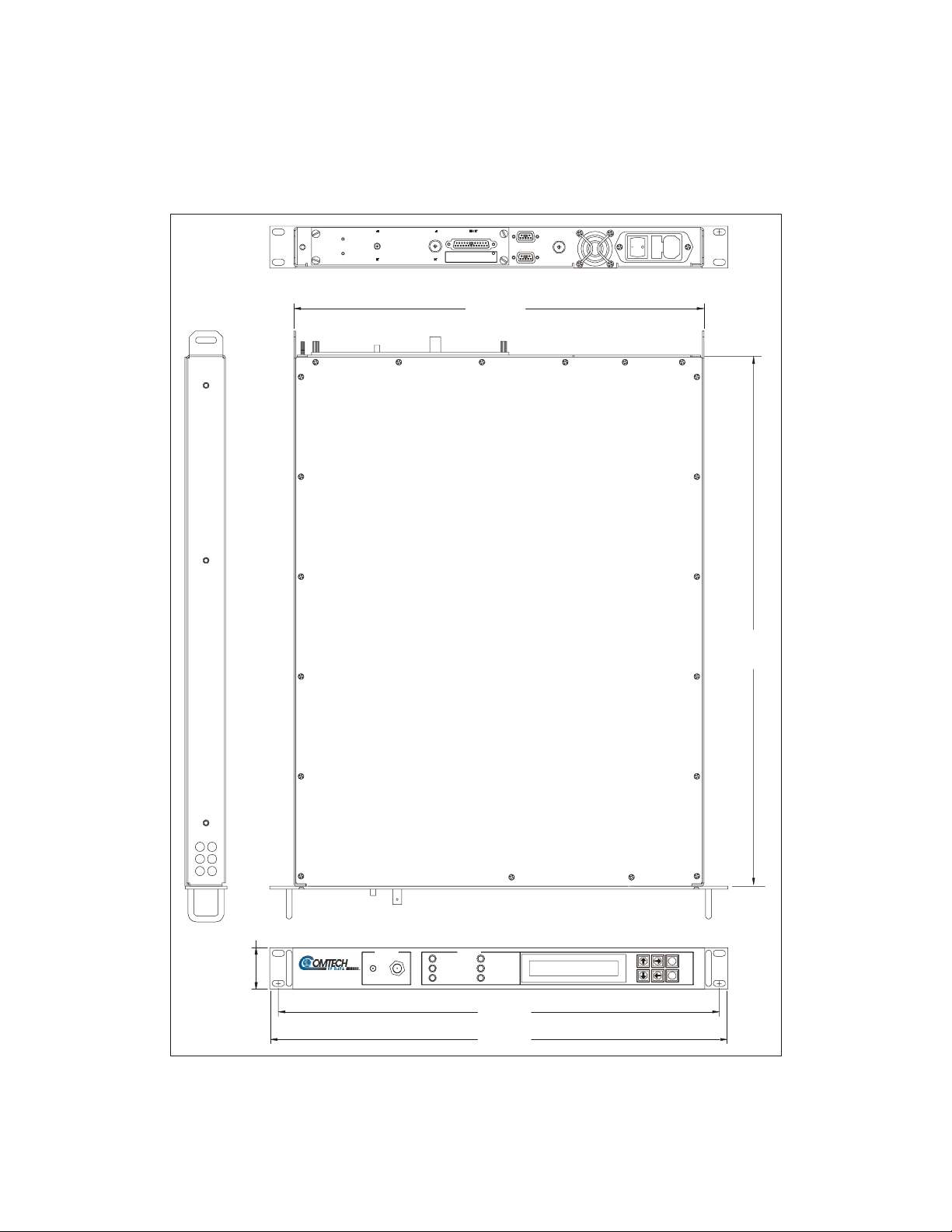
1.5 DIMENSIONAL ENVELOPE (UT-4579)
Dimensions are shown in both inches and centimeters.
17.00
(432)
1.75”
(4.45)
UT-4579
UPCONV ERTER
SAMPLE STATUS
RF IF
POWER ON
TRANSMIT
REMOTE
ON LINE
FAULT
STORED FAULT
18.25
(46.35)
19.0
(48.3)
Figure 5. Dimensional Envelope
22.00
(55.9)
ENT
CLR
7
Page 24

UT4579 X-Band Up Converter MN/UT4579.IOM
Introduction Rev. 0
NOTES:
8
Page 25

2.1 UNP ACKING AND INSPECTION
Inspect the shipping container for damage. If the shipping containers are damaged, keep
them until the contents of the shipment have been carefully inspected and checked for
normal operation.
Remove the packing list from the outside of the shipping carton. Open the carton and
remove the contents, checking the contents against the packing list. Verify completeness
of the shipment and that the unit functions correctly. If damage is evident, contact the
carrier and Comtech EF Data immediately and submit a damage report.
Chapter 2. Installation
Unpacking and Inspection 9 Rack Mount Installation 9 Prime Power Connection 10 Cable Connections 10
If the unit needs to be returned to Comtech EF Data, please use the original shipping
container.
2.2 RACK MOUNT INSTALLATION
The UT-4579 Up Converter is designed for installation in a standard 19 inch rack cabinet
or enclosure. The converter chassis requires 1-3/4 inches of panel height space.
Adequate air ventilation should be provided on both sides of the rack mounted
equipment.
If the converter is to be mounted on slides, the slides must be the Comtech EF Data rack
slides provided with the converter. Mount the slides on the sides of the converter chassis
with the mounting hardware provided. Then, install the slide rails in the rack cabinet
enclosure.
Slide the converter into the front of the rack cabinet until the rear of the front panel
contacts the mounting surface of the cabinet. Secure the converter to the rack cabinet
with four screws inserted through the converter’s front panel slotted holes.
9
Page 26

UT4579 X-Band Up Converter MN/UT4579.IOM
Installation Rev. 0
2.3 PRIME POWER CONNECTION
The detachable power cord mates with the AC Prime power receptacle on the rear of the
converter chassis. A power cord for connection to 90 to 125 Vac, or 205 to 240 Vac,
power sources is provided with the converter.
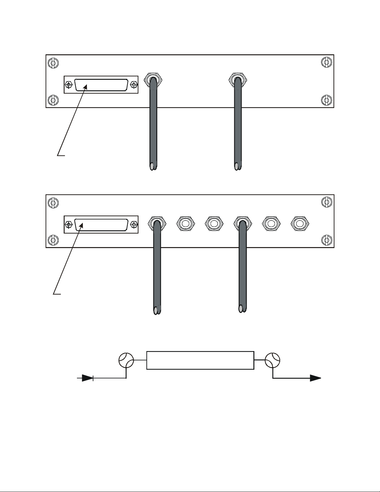
2.4 CABLE CONNECTIONS
Connect the signal cables to the connectors on the rear panel as shown in Figure 6. The
cable signal functions are listed in Table 2.
2.4.1 REAR PANEL CONNECTIONS
Table 2. Rear Panel Connectors
Connector Description
Prime Power AC Prime Power Input (AC POWER), Optional –48 VDC
J1: Serial Communications Interface for EIA-485 or EIA-232C COMM links (COM 1)
J2: External Reference Oscillator Input
J3: High Speed Bus (HSB)
J4: Converter IF Input (IF)
J5: Converter RF Output (RF)
J6: IF TSM Switching Loop Input (LP IN)
J7: RF TSM Switching Loop Input (LP IN)
J8: IF TSM Switching Loop Output (LP OUT)
J9: RF TSM Switching Loop Output (LP OUT)
P1: Summary Fault Output (RELAY)
10
Page 27

UT4579 X-Band Up Converter MN/UT4579.IOM
Installation Rev. 0
2.4.2 EIA-485/EIA-232C INTERFACE (COM 1), CONNECTOR J1
The EIA-485/EIA-232C Interface connector, J1, is 9 pin "D" type DB9F connector
socket. The pin-out specifications for EIA-485 are contained in Table 3 and Table 4. The
specification for EIA-232C is contained in Table 5. The mating connector is a DB9M.
Table 3. J1, 2 Wire EIA-485 Interface Pin-Out Table 4. J1, 4 Wire EIA-485 Interface Pin-Out
Pin # Description
1 GND; Ground
2
3
4 +RX/TX; Signal
5 -RX/TX; Signal Complement
6
7
8 +RX/TX; Signal
9 -RX/TX; Signal Complement
Note: Pins 8 & 9 are the loop to the next converter.
Pin # Description
1 GND; Ground
2
3
4 +TX; Signal
5 -TX; Signal Complement
6
7
8 +RX; Signal
9 -RX; Signal Complement
Table 5. J1, EIA-232C Interface Pin-Out
Pin # Description
1
2 TD; Transmit Data
3 RD; Receive Data
4
5 GND; Ground
6 DSR; Unit Ready - always high.
7 RTS; Request to Send. Looped to CTS.
8 CTS; Clear to Send
9
11
Page 28

UT4579 X-Band Up Converter MN/UT4579.IOM
Installation Rev. 0
2.4.3 HIGH SPEED BUS (HSB), CONNECTOR J3
The High Speed Bus connector, J3, is 25 pin "D" type DB25F connector socket. The pinout specifications is contained in Table 6. The mating connector is a DB25M.
Note: This is not a “straight through” cable assembly. Contact Comtech EF Data for detailed
wire drawings when cabling between converters.
Table 6. J3, High Speed Bus Connector Pin-Out
Pin # Description Pin # Description Pin # Description
1 Cntl_12 10 Aux_3 18 Cntl_3
2 Cntl_10 11 Aux_1 19 Cntl_1
3 Cntl_8 12 -Rx/Tx 20 +14V Out
4 Cntl_6 13 GND 21 +14V In
5 Cntl_4 14 Cntl_11 22 GND
6 Cntl_2 15 Cntl_9 23 Aux_2
7 Cntl_In 16 Cntl_7 24 GND
8 +14V Out 17 Cntl_5 25 +Rx/Tx
9 +14V In
2.4.4 SUMMARY FAULT OUTPUT (RELAY), CONNECTOR P1
The summary fault output connector, P1, is 9 pin "D" type DB9M connector. The pinout specifications are contained in Table 7. The mating connector is a DB9F.
Table 7. P1, Summary Fault Connector Pin-Out
Pin # Description
1 Summary Fault NC
2 Summary Fault NO
3
4
5 Ground
6 Summary Fault Com
7 External Fault Input
8
9
Notes: 1
Pin 1 to Pin 6: Fault.
Pin 2 to Pin 6: No Fault.
2
Pin 7 to Pin 5: Forced Fault. Typically used with external group delay equalizers
3
12
Page 29
UT4579 X-Band Up Converter MN/UT4579.IOM
Installation Rev. 0
Prime Po wer Cord In put
5/10 MHz Ref. Osc. Input J2
Summary Fault Relay Output
Serial Comm. Interface
(EIA-485 / EIA-232C )- COM 1
High Speed Bu s (HSB)
P1
J1
J3
Power
Supply
Monitor & Control Assembly
Referenc e
Oscillat or
Fine
Step
Module
IF Outpu t (IF)
IF Loop Input (LP I N)
IF Loop Outpu t (LP OUT)
RF Input (RF)
(Not Used)
(Not Used)
J4
J6
J8
J5
J7
J9
Receive
I/O S witch
Module
RF Conve rter
Loop
Module
Figure 6. Cable Interconnect Diagram
2.4.5 CABLE CONNECTIONS FOR NON-REDUNDANT SYSTEM OPERATION
In non-redundant converter configuration the converter has an Input/Output Module
(IOM-XX) for the RF input and the IF Output. A converter with a Transmit Switch
Module may be operated in a non-redundant configuration if an IOM is unavailable.
Figure 7 is an illustration of the converter cable connections with an IOM installed.
Figure 8 is an illustration of the converter cable connections with a TSM installed.
2.4.6 CABLE CONNECTIONS FOR REDUNDANT SYSTEM OPERATION
In subsystems where a redundant converter configuration is used, the backup converter
has an Input/Output Module (IOM-XX) and the online converters have Transmit Switch
Modules (TSM-XX) which switch to the backup converter when a fault is detected.
Redundant system operation is discussed in Appendix A, Redundant System Operation.
Sum
13
Page 30
UT4579 X-Band Up Converter MN/UT4579.IOM
Installation Rev. 0
IOM-XX
NO
CONNECTION
TSM-XX
IF
OUTPUT
Figure 7. Non-Redundant Converter Configuration
J3 HSB IF
J4
J4 J6 J8
LP OUTLP IN RF
J5
RFIFJ3 HSB
RF
INPUT
J5
J7 J9
LP OUTLP IN
IF OUTPUT RF INPUT
NO
CONNECTION
UP CONVERTER - TSM
IF INPUT
Figure 8. Non-Redundant Converter Configuration With Transmit Switch Module (TSM-XX) Installed
RF OUTPUT
14
Page 31

3.1 OVERVIEW
This chapter contains instructions for operating the converter. Illustrations of the front
and rear panels are provided showing the keypad for operator input commands, LCD
Display, LED status indicators, and the connectors. Tables are provided to show the
control and operating functions of the converter.
The front and rear panels are shown below. Table 8 lists of the operating functions for the
keypad, LCD display, LED indicators and test sample connections on the front panel.
Chapter 3. System Operation
Overview 15
Switching Power ON 17
Operation 17
Figure 9. Front Panel
Figure 10. Rear Panel (with TSM Module and optional REF Output)
15
Page 32

UT4579 X-Band Up Converter MN/UT4579.IOM
System Operation Rev. 0
Table 8. Operating Functions – Front Panel
Item Reference Designation Functional Description
Enter key Enters commands into the converter.
ENT
Clear key Clears commands and data selected and not entered .
CLR
Right Arrow key Selects functions and the menu operating data.
Left Arrow key Selects functions and the menu operating data.
Up Arrow key Selects the operating menu and data values.
Down Arrow key Selects the operating menu and data values.
LCD Display Displays commands and data entered
UT_4579-1
into the key-pad.
SW VER 4.06 SN45793513
Indicator Color Function
POWER ON
TRANSMIT
REMOTE
ON LINE
FAULT
STORED FAULT
Item Reference
RF SAMPLE RF An SMA connector test point to sample RF.
IF SAMPLE IF A BNC connector test point to sample IF.
Green
Yellow
Yellow
Yellow
Red
Red
Designation
Prime power is applied when the light is on.
Transmit function operating when the light is on.
In Remote Control Mode when the light is on.
Operating on-line to transmit data when the light is on.
Fault condition exists when the light is on.
Faults stored and logged when the light is on.
Function
16
Page 33

UT4579 X-Band Up Converter MN/UT4579.IOM
System Operation Rev. 0
3.2 SWITCHING POWER ON
Before turning the Prime Power Switch to the ON position, check to ensure that the
installation is complete, and verify that the converter is connected to the proper prime
power source, RF Output and IF Input.
Switch the ON/OFF Prime Power Switch on the rear panel to ON. Verify that the
cooling fan is operating, and that the POWER ON LED STATUS indicator light is on.
After the AC power is switched on and before pressing the buttons on the keypad, the
LCD display message should be similar to:
UT-4579-X
SW VER 4.06 SN4579XXXX
3.3 OPERATION
Local operation of the RF Up Converter is controlled by operator input commands
initiated through the six button key-pad on the front panel shown in Figure 11. The keypad is the local operator's interface to control, configure and monitor the status of the
converter. Operator inputs and commands entered into the key-pad are displayed by the
front panel twenty-four character, two line, LCD display. See Appendix B for Remote
Control.
There are six operating command functions: Configuration, Pre-Select, Monitor Status,
Currents Faults, Stored Faults and Utility Functions. A flow chart for selecting the
commands, operating menus, and data inputs is shown in Figure 12 through Figure 20.
ENT
CLR
Figure 11. Keypad
17
Page 34

UT4579 X-Band Up Converter MN/UT4579.IOM
System Operation Rev. 0
--------UT-4579--------
-SOFTWARE VERSION-4.06-
---------SELECT---------
----CONFIGURATION-MENU--
---------SELECT---------
----PRE-SELECT MENU-----
-
---------SELECT---------
--MONITOR-STATUS-MENU---
---------SELECT---------
--CURRENT-FAULTS-MENU---
---------SELECT---------
---STORED-FAULTS-MENU---
LEGEND
---------SELECT---------
-UTILITY-FUNCTIONS-MENU-
DISPLAY
---------SELECT---------
--MONITOR-STATUS-MENU---
Figure 12. Converter Operating Command Functions
KEY-PAD
ENT
CLR
18
Page 35

UT4579 X-Band Up Converter MN/UT4579.IOM
System Operation Rev. 0
---------SELECT---------
----CONFIGURATION-MENU--
ENTER
FREQ= 79XX.XXX-MHz-----
ATTN=-10.00-DB---Tx=OFF-
----EXTERNAL-5-MHz------
--REFERENCE-PRESENT-----
--ENTRY-MODE-=-REMOTE---
-COLD-START-=-DISABLED--
FAULT RECOVERY:-MANUAL--
------------------------
REDUNDANCY-CONFIG?-OFF--
------------------------
* Displayed only when there is
a 5/10 MHz reference input.
LEGEND
DISPLAY
---------SELECT---------
--MONITOR-STATUS-MENU---
KEY-PAD
ENT
CLR
Figure 13. Configuration Menu Commands - Redundancy OFF.
19
Page 36

UT4579 X-Band Up Converter MN/UT4579.IOM
System Operation Rev. 0
---------SELECT---------
----CONFIGURATION-MENU-ENTER
FREQ= 79XX.XXX-MHz-----
ATTN=-10.00-DB---Tx=OFF-
** Manual when “Redunda ncy
Config ON” and not in “BU”
----EXTERNAL-5-MHz------
--REFERENCE-PRESENT-----
--ENTRY-MODE-=-REMOTE---
-COLD-START-=-DISABLED--
FAULT RECOVERY:-MANUAL--
------------------------
REDUNDANCY-CONFIG?-OFF--
------------------------
LEGEND
* Displayed only when there is
a 5/10 MHz reference input.
ENT + DOWN + ENT
CLR
KEY-PAD
DISPLAY
---------SELECT---------
--MONITOR-STATUS-MENU---
REDUNDANCY-CONFIG?-ON---
-CONVERTER-#-XX---------
ENT
CLR
Figure 14. Configuration Menu Commands - Redundancy ON, Backup Unit Not Selected
20
Page 37

UT4579 X-Band Up Converter MN/UT4579.IOM
System Operation Rev. 0
---------SELECT---------
----CONFIGURATION-MENU-ENTER
FREQ= 79XX.XXX-MHz-----
ATTN=-10.00-DB---Tx=OFF-
REDUNDANCY-CONFIG?-ON---
-CONVERTER-#-01---------
----EXTERNAL-5-MHz------
--REFERENCE-PRESENT-----
--ENTRY-MODE-=-REMOTE---
-COLD-START-=-DISABLED--
FAULT RECOVERY:-MANUAL--
------------------------
REDUNDANCY-CONFIG?-OFF--
------------------------
ENT + DOWN + ENT
EN T + UP + E NT
REDUNDANCY-CONFIG?-ON---
-CONVERTER-#-XX---------
* Displayed only
when there is
a 5/10 MHz
reference input.
ENT + RIGHT+UP + ENT
LEGEND
ENT + RIGH T+ UP . . . +UP + EN T
REDUNDANCY-CONFIG?-ON---
-CONVERTER-#-BU---1:NN--
-CONVERTER-123456789ABC-
-AUTO/MAN-AAM-----------
CONV-01-OFFSET=+00.00-DB
--ACTIVATE-BACKUP:-NO---
-CONV-#01-FRQ=XXXX.XXX-
-ATEN=10.00---MANUAL-OK-
KEY-PAD
ENT
DISPLAY
---------SELECT---------
--MONITOR-STATUS-MENU---
CLR
Figure 15. Configuration Menu Commands -
Redundancy ON and Backup Unit Selected
21
Page 38

UT4579 X-Band Up Converter MN/UT4579.IOM
System Operation Rev. 0
---------SELECT---------
-----PRE-SELECT-MENU---ENTER
-DISPLAY-PRE-SELECT-XX--
XXXX.XXX-MHz--XX.XX--DB-
-CONFIGURE-CONVERTER-TO-
-----PRE-SELECT?-XX-----
-PROGRAM-PRE-SELECT-XX-XXXX.XXX-MHZ---XX.XX-DB-
----CLEAR-DATA-FROM-----
-----PRE-SELECT?-XX-----
LEGEND
DISPLAY
---------SELECT---------
--MONITOR-STATUS-MENU---
KEY-PAD
ENT
CLR
Figure 16. Pre-Select Menu Commands
---------SELECT---------
---MONITOR-STATUS-MENU--
ENTER
15VDC=-15.6--14VDC=-14.0
-VCC-=5.0---5VDis-=-4.0-
--CONVERTER-TEMP-=-+50C-
--IFLO-TUNING-=-X.X-V---
SYNTH.-TUNING-=-X.X-V---
--COARSE=X.XX-FINE=X.XX-
LEGEND
DISPLAY
---------SELECT---------
--MONITOR-STATUS-MENU---
KEY-PAD
ENT
CLR
Figure 17. Monitor Status Menu Commands
22
Page 39

UT4579 X-Band Up Converter MN/UT4579.IOM
System Operation Rev. 0
---------SELECT---------
---CURRENT-FAULTS-MENU-ENTER
------POWER-FAULTS-----15VDC=OK-14VDC-OK-VCC=OK
-INFO-LOCK-DETECT-=-OK-REFERENCE-LOCK-DET-=-OK-
SYNTH-FAULTS:-SUM-LD=OKFINE-LD=OK--COARSE-LD=OK
-CONV-TEMPERATURE-=-OK--
--HIGH-SPEED-BUS-=-OK---
LEGEND
DISPLAY
---------SELECT---------
--MONITOR-STATUS-MENU---
KEY-PAD
ENT
CLR
Figure 18. Current Faults Menu Commands
---------SELECT---------
---STORED-FAULTS-MENU--ENTER
TOTAL-FAULTS-STORED:--XX
LAST-19:20:05---05/19/02
----CLEAR-ALL-STORED----
-------FAULTS?-NO-------
LEGEND
DISPLAY
---------SELECT---------
--MONITOR-STATUS-MENU---
ENT + UP
to scroll thru
Stored Faults
KEY-PAD
ENT
CLR
ST-FAULT-XX-----19:20:05
OK-FINE-LOCK----05/19/02
CLR to return
Figure 19. Stored Faults Menu Commands
23
Page 40

UT4579 X-Band Up Converter MN/UT4579.IOM
System Operation Rev. 0
---------SELECT---------
-UTILITY-FUNCTIONS-MENUENTER
----TIME:-10:22:05AM----
-----DATE:-05/19/02-----
---SERIAL-MODE=EIA232C-ADDR=XXX-BAUD=YYYY-P=ZZ-
-DISPLAY-CONTRAST-=-XX-DISPLAY-BRIGHTNESS-=-XX-
--REFERENCE-FREQUENCY---
----ADJUSTMENT-=-XXX----
---CONVERTER-SLOPE------
----ADJUSTMENT-=-X.X----
-------LAMP-TEST--------
-----------OFF----------
LEGEND
DISPLAY
---------SELECT----- ----
--MONITOR-STATUS-MEN U---
KEY-PAD
ENT
CLR
Figure 20. Utility Function Menu Commands
24
Page 41

UT4579 X-Band Up Converter MN/UT4579.IOM
System Operation Rev. 0
3.3.1 CONVERTER COMMANDS
The converter commands are in a tree structured menu format designed for access and
execution of all control functions, and to prevent the execution of an invalid entry by the
operator. When the prime power is turned on, the LCD display will contain a message
indicating the converter model number and the version number of the firmware installed
in the converter.
To select a Command Function press the "ENT" button on the keypad. The LCD display
will indicate:
SELECT
CONFIGURATION MENU
This will provide the local operator access to the Command Function Menus, which is the
top level structure to start the selection of Command Function Menus to input into the
converter. To sequence to the next Command Function Menu press a "DOWN" or "UP"
arrow button on the keypad. The converter will step to the next Command Function
Menu each time a "DOWN" or "UP" arrow button is pressed. The current Command
Function Menu will be displayed on the LCD display. The Command Function Menus
are shown in Figure 12.
To select a specific Command Function Menu press the "ENT" keypad button. If a
function is selected in error, press the clear ("CLR") button which will return the
converter to the main command menus to allow the selection of another function. Any
one of the six Command Function Menus can be selected using this procedure.
Once a Command Function has been selected, use the "RIGHT" or "LEFT" arrow keypad buttons to sequence through the Operating Mode Commands. Each of the modes
will be displayed on the LCD display. A specific operating mode is selected by pressing
the "ENT" button. If an mode is selected in error, press the clear ("CLR") button which
will return the converter to the operating menus to allow the selection of another mode.
When an operating mode is selected, a parameter or a digit within the parameter will be
flashing on the LCD display. Use the "RIGHT" and "LEFT" arrows buttons to sequence
through the parameters or digits to select the next parameter or digit. A specific
parameter or value is selected by pressing the "ENT" button. If a parameter or value is
selected in error, press the clear ("CLR") button which will return the converter to the
original parameter or value to allow another selection.
After selecting a parameter or digit, use the "UP" or "DOWN" arrow buttons to select the
next parameter, or to increment or decrement the value of a digit. A specific new
parameter or new value is selected by pressing the "ENT" button. If a parameter or value
is selected in error, press the clear ("CLR") button which will return the converter to the
original parameter or value to allow another selection.
Each time the clear ("CLR") button is pressed, the converter will return to the menu level
prior to the last "ENT" command.
25
Page 42

UT4579 X-Band Up Converter MN/UT4579.IOM
System Operation Rev. 0
3.3.2 CONFIGURATION FUNCTIONS MENU
The Configuration Functions are as follows:
3.3.2.1 FREQUENCY OPERATING MODE
Frequency (FREQ):
Displays the current converter frequency in MHz, and allows the selection of a
new frequency channel between RF
Low
to RF
MHz (e.g.; 7900.000 to
High
8400.000 MHz) in 125 KHz steps through keypad inputs.
Attenuation (ATTN):
Input and displays the converter attenuation setting which is selected between
0.00 to 25.00 in 0.25 dB steps. The default setting is 10.00 dB.
Tx: The converter is ON or OFF. The default mode is OFF.
3.3.2.2 EXTERNAL REFERENCE
External Reference:
The External Reference is displayed only when the 5 or 10 MHz external
reference input to the converter is present.
3.3.2.3 ENTRY MODE/COLD START
The entry mode is Local or Remote. The default is Remote.
COLD Start:
The COLD Start Mode, if enabled, mutes the converter output signal for a predetermined time, 15 minutes, after power is applied to the converter to ensure that
the reference oscillator is stable. The default mode is Disabled. This function is
disabled in redundant systems.
3.3.2.4 FAULT RECOVERY
Fault Recovery:
Fault Recovery is Manual or Auto. The default is Auto.
3.3.2.5 REDUNDANCY MODE
Refer to Appendix A, Redundant System Operation.
3.3.3 PRE-SELECT FUNCTION MENU
3.3.3.1 D
Displays the frequency and attenuation pre-selects for the converter. One to 32
frequencies can be pre-selected. If no frequencies have been pre-selected, the LCD
display will indicate "NONE".
ISPLAY PRE-SELECT
26
Page 43

UT4579 X-Band Up Converter MN/UT4579.IOM
System Operation Rev. 0
3.3.3.2 CONFIGURE CONVERTER TO PRE-SELECT
This command allows the local operator to pre-select from 1 to 32 frequencies to pre-set
a programmed frequency channel and attenuation setting.
3.3.3.3 CLEAR DATA FROM PRE-SELECT
This command allows the local operator to clear a pre-set frequency and attenuation
setting from a pre-selected converter.
3.3.3.4 PROGRAM PRE-SELECT
This command allows the local operator to input a pre-set frequency channel and
attenuation settings into a converter.
3.3.4 MONITOR STATUS FUNCTION MENU
Monitors and displays the status of:
15 and 14 VDC power supplies.
Converter internal temperature.
IFLO tuning voltage level.
Synthesizer Sum, Coarse and Fine Loop tuning.
3.3.5 CURRENT FAULTS FUNCTION MENU
Displays the status of the current fault conditions. The LCD display will indicate "FT"
when a fault condition exists. The display will indicate "OK" when a fault has not
occurred.
3.3.5.1 POWER FAULTS
Displays the DC voltage power supply faults.
15 VDC Power Supply.
14 VDC Power Supply.
VCC voltage.
3.3.5.2 CONVERTER OSCILLATOR FAULTS
Displays the converter oscillator faults:
IFLO Lock Detect.
Reference Oscillator Lock Detect (only present if external reference is detected.).
27
Page 44

UT4579 X-Band Up Converter MN/UT4579.IOM
System Operation Rev. 0
3.3.5.3 SYNTHESIZER FAULTS
Displays the synthesizer faults:
Sum Loop Detect.
Coarse Loop Detect.
Fine Loop Detect.
3.3.5.4 CONVERTER OVER TEMPERATURE FAULT
Displays a converter temperature fault condition.
3.3.6 STORED FAULTS
The converter displays a total of 100 faults which are date and time stamped and stored in
memory as they occur. The stored faults remain in memory until a clear command is
entered. When the number of faults reaches 100, the 100th fault will display ER.
3.3.6.1 TOTAL STORED FAULTS
Displays the total number of faults stored. The most recent fault stored is displayed on
the LCD display.
3.3.6.2 CLEAR ALL STORED FAULTS
Input command to clear all faults. The command is "YES" or "NO' which is displayed on
the LCD display.
3.3.6.3 DISPLAY STORED FAULT
The local operator can sequence through the stored faults starting with the most recent
fault. The fault number, time, description and date is displayed on the LCD display.
28
Page 45

UT4579 X-Band Up Converter MN/UT4579.IOM
System Operation Rev. 0
3.3.7 UTILITY FUNCTION MENU
The local operator can input commands to the following Utility Functions which are
displayed on the LCD display:
TIME. Military time is used in hours, minutes and seconds
DATE. The date is displayed in month, day and year
Serial MODE (communications link)
EIA-485 or EIA-232C
Physical Address. The default address starts from one (001)
BAUD (Rate). The default baud rate is 9600
PARITY. Even, Odd or None
Display Controls
DISPLAY CONTRAST. The default is 15, with values from 0 to 30
DISPLAY BRIGHTNESS. The default is 15, with values from 0 to 30
REF Adjust
REFERENCE FREQUENCY ADJUSTMENT. The default tuning adjustment is 87, with
values from 0 to 255
29
Page 46

UT4579 X-Band Up Converter MN/UT4579.IOM
System Operation Rev. 0
NOTES:
30
Page 47

Appendix A. Redundant System
Operation
Overview 31
Backup Converter 32
Redundant Configurations 33
A.1 OVERVIEW
The Comtech EF Data UT-4579 Up Converter is configured for redundant system
operation using distributed protection switching in an active "Daisy Chain" configuration.
Comtech EF Data's Proprietary "Daisy Chain" configuration distributes the converter
protection switching functions in the converters.
This provides a system capability to backup from 1 to 12 online converters. A High
Speed Bus (HSB) provides the communications interface between the backup and online
converters to detect faults and reconfigure the subsystem to replace the failed converter.
When a faulted converter is removed from active operation, it is detached from the active
converter chain by separating the converter from its switch module, leaving the active
online converter chain intact through the switch module. The chain can be extended
without affecting the online converter operation.
The active "chained" converters in a redundancy subsystem can also be indirectly
controlled through the backup converter using the remote serial communication link -
this capability is discussed in Appendix B, Remote Control.
31
Page 48

UT4579 X-Band Up Converter MN/UT4579.IOM
Redundant System Operation Rev. 0
A.2 BACKUP CONVERTER
The "Daisy Chain" terminates in the backup converter. The backup converter has a
microprocessor which performs fault detection, self reconfiguration and the logical
switching functions. If the backup converter does not have a fault, it will assume the
frequency and attenuation of the faulted converter and compensate for the chain losses.
This capability is accomplished through the operation of the High Speed Bus (HSB) and
the online converter detachable switch modules.
A.2.1 HIGH SPEED BUS (HSB)
In the "Daisy Chain" configuration, the backup converter communicates with the online
units through the high speed interface bus (HSB). The backup converter is able to detect
faults and reconfigure itself to replace the faulted converter. The HSB interface is also
used in the backup converter to monitor configuration changes made to an online
converter. Changes in frequency, gain, or polarity are immediately entered into the
backup table as well as information from new online units. The high speed bus does not
interfere with the remote serial communication link access to any of the converters in the
chain.
A.2.2 DETACHABLE MODULES
Comtech EF Data's Converter is designed with a detachable Input/Output Module (IOM)
which contain the signal path connectors. The IOM is utilized for single thread
operation, or for testing of the unit.
For redundant "Daisy Chain" operations, the on-line up Converter is provided with a
detachable Transmit Switch Module (TSM) replacing the IOM.
A.2.2.1 UP CONVERTER SWITCHING
Up converter switching is implemented with a detachable Transmit Switch Module
(TSM). The TSM contains IF and RF transfer switches for input/output looping of the
signal. Options for the TSM include SMA connectors for the RF output signal, and 50 Ω
or 75 Ω BNC connectors for the IF.
32
Page 49

UT4579 X-Band Up Converter MN/UT4579.IOM
Redundant System Operation Rev. 0
A.3 REDUNDANT CONFIGURATIONS
Comtech EF Data UT-4579 Up Converters can be configured in several different
redundant subsystem "Daisy Chain" configurations to meet the reliability requirements of
a communication system. These configurations include:
Table 9. 4579 Up Converter Configurations
1:1 Redundant Subsystems
Single Source IF Input Configuration
The online converter uses an IF and RF transfer switch to switch the IF input and
RF output signals. A single switched IF input and RF output is provided to and
from the online converter. The transfer switches are contained in the Transmit
Switch Module (TSM) installed in the online converter. When a fault occurs in the
online converter, the TSM is de-activated to switch out the online converter, and
switch the IF input and RF output to the backup converter. Figure 21 is an
illustration of the cable connections between the converters. Figure 22 is a block
diagram of this 1:1 redundant converter configuration.
Dual Source IF Input Configuration
Two IF inputs, IF input #1 (priority) and IF input #2, are switched in the Transmit
Switch Module (TSM) to provide redundant operation of the converters. The
converters provide two switched RF outputs, RF output #1 (priority) and RF output
#2. If converter #1 faults, converter #2 backs up the priority channel and IF signal
#2 and RF signal #2 are not operational. Figure 24 is an illustration of the cable
connections between the converters. Figure 25 is a block diagram of the 1:1
redundant, dual source IF input, converter configuration.
1:N Redundant Subsystems
IF and RF transfer switches in the TSM are used to switch the IF input and RF
output of a faulted online converter to the backup converter. The IF input and RF
output to the redundant converter subsystem is connected to online converter #N.
Figure 26 is an illustration of the cable connections between the converters.
Figure 27is a block diagram of this 1:N redundant "Daisy Chain" converter
configuration.
33
Page 50

UT4579 X-Band Up Converter MN/UT4579.IOM
Redundant System Operation Rev. 0
IOM-XX
J4
IF
J4 J6 J8
IF
IF
INPUT
LP OUTLP IN RF
J5
RF
J5
RF
OUTPUT
J7
LP IN
J9
LP OUTJ3 HSB
Figure 21. 1:1 Redundant Configuration - Single Source IF Input w/IOM and TSM-XX Installed
UP CONVERTER - IOM
(BACKUP UNIT)
IF
LOAD
IF INPUT
Figure 22. 1:1 Redundant Configuration Diagram - Single Source IF Input w/IOM-XX and TSM-XX
UP CONVERTER - TSM
RF OUTPUT
Installed
RF
LOAD
34
Page 51

UT4579 X-Band Up Converter MN/UT4579.IOM
A
Redundant System Operation Rev. 0
IF Load
or
Loop to
Next Unit
IF In
LP In
BU EQ
LP Out
IF In
IF Out
EQ
Out
EQ
IF Out
In
Up Converter - IOM
(Backup Unit)
Up Converter - TSEQM
(On line)
P1 - Pin 7
larm Cable
EQ
NO
(Closed When
EQ Faults)
Figure 23. 1:1 Redundant Configuration Diagram -
Single Source IF Input with IOM-XX and TSEQM-XX Installed
IOM-XX
J4
J5
RF OutIF In
LP Out
RF Load
or
Loop to
Next Unit
LP In
RF Out
J3 HSB
IF
J4 J6
IF
IF
INPUT #1
(PRIORITY)
LP IN
J8
LP OUT
IF
INPUT #2
RF
RF
RF
OUTPUT #1
(PRIORITY)
LP IN
J9J7J5
LP OUT
RF
OUTPUT #2
Figure 24. 1:1 Redundant Configuration - Dual Source IF Input
35
Page 52

UT4579 X-Band Up Converter MN/UT4579.IOM
Redundant System Operation Rev. 0
IF INPUT #2
IF INPUT #1
(PRIORITY)
UP CONVERTER
(BACKUP UNIT)
UP CONVERTER
Figure 25 1:1 Redundant Configuration Diagram
Dual Source IF Input with IOM-XX and TSM-XX Installed.
RF OUTPUT #2
RF OUTPUT #1
(PRIORITY)
36
Page 53

UT4579 X-Band Up Converter MN/UT4579.IOM
Redundant System Operation Rev. 0
BACKUP CONVERTER (BU)
IOM-XX
J4
J5
TO
CONN. J3 ON
CVTR. #3
J4
IF
LP IN
IF
INPUT
#1
J4 J6 J8
IF
LP IN RF
IF
INPUT
#2
IF
J6 J5 J9
J8
LP O UT
RF
RF
LP IN
J7
LP O UT
RF
OUTPUT
#1
J5 J9
J7
LP OUT
TO
CONN. J6
ON
LP IN
RF
OUTPUT
#2
LP O UT
CVTR. #3
CONVERTER No. 1
CONVERTER No. 2
TO
CONN. J7 ON
CVTR. #3
TO
CONN. J3 ON
CVTR. #(N-1)
TO
CONN. J8 ON
CVTR. #( N-1)
TO
CONN. J9 ON
CVTR. #( N-1)
CONVERTER No. N
J4 J6 J8
IF
LOAD
J3
HSB
IF
LP OUTLP IN
IF
INPUT
#N
J5 J9
J7
RF LP IN LP OUT
RF
OUTPUT
#N
RF
LOAD
Figure 26. 1:N Redundant Configuration with IOM-XX and TSM-XX Installed
37
Page 54

UT4579 X-Band Up Converter MN/UT4579.IOM
Redundant System Operation Rev. 0
BACKUP UP CONVERTER
(BU)
RF
IF
INPUT
#1
IF
INPUT
#2
IF
INPUT
#3
IF
INPUT
#4
TO CVTR. #5 IF
(LP IN) CONN. J6
UP CONVERTER #1
UP CONVERTER #2
UP CONVERTER #3
UP CONVERTER #4
TO CVTR. #5 RF
(LP IN) CONN. J7
OUTPUT
#1
RF
OUTPUT
#2
RF
OUTPUT
#3
RF
OUTPUT
#4
IF
LOAD
IF
INPUT
#N
TO CVTR. #(N-1) IF
(LP OUT) CONN. J8
UP CONVERTER #N
TO CVTR. #(N-1) RF
(LP OUT) CONN. J9
Figure 27. 1:N Redundant Configuration Diagram
with IOM-XX and TSM-XX Installed
RF
LOAD
RF
OUTPUT
#N
38
Page 55

UT4579 X-Band Up Converter MN/UT4579.IOM
Redundant System Operation Rev. 0
A.4 REDUNDANT SYSTEM CONFIGURATION
A.4.1 INITIAL CONFIGURATION
Redundant system configuration is controlled from the converter’s front panel
configuration menu. Each online unit is assigned a redundancy configuration address.
This address is dependent on the location of the online converter with reference to the
backup. The unit closest to the backup must be converter # 1. The next unit down must
be converter # 2. Figure 28 shows the appropriate entries for a 1:3 system
STATUS
POWER ON
TRANSMIT
REMOTE
ON LINE
FAULT
STORED FAULT
REDUNDANCY-CONFIG?-ON---
-CONVERTER-#-BU---1:03--
STATUS
POWER ON
TRANSMIT
REMOTE
STATUS
POWER ON
TRANSMIT
ON LINE
FAULT
STORED FAULT
ON LINE
FAULT
REDUNDANCY-CONFIG?-ON---
-CONVERTER-#-01---------
REDUNDANCY-CONFIG?-ON---
-CONVERTER-#-02---------
REMOTE
STATUS
POWER ON
TRANSMIT
STORED FAULT
ON LINE
FAULT
REDUNDANCY-CONFIG?-ON---
-CONVERTER-#-03---------
REMOTE
Configure the online units first, and then configure the backup unit. Redundant polling
starts when the backup is configured. If this polling starts before the online units are
configured, a high-speed bus fault will result. This fault should clear when configuration
is completed. At this point, control of the redundant system is performed from the backup
converter.
STORED FAULT
Figure 28. 1:3 Front Panel Displays
39
Page 56

UT4579 X-Band Up Converter MN/UT4579.IOM
A
A
A
Redundant System Operation Rev. 0
A.4.2 AUTOMATIC CONFIGURATION VERIFICATION
The backup converter has a menu that allows the operator to choose, on a converter-byconverter basis, manual (M) or automatic (A) operating mode.
Figure 29 shows the system configured for automatic (A) operation. In this mode, failure
of an online converter will automatically cause a switchover to the redundant unit to
occur. In the field, the simplest way to test this mode is to turn off an online unit. The
AUTO/MANUAL selection is made in the converter. The online units will report their
status as show in Figure 29.
STATUS
POWER ON
ON LINE
-CONVERTER-123456789ABC-
TRANSMIT
FAULT
-AUTO/MAN--AAA-----------
REMO TE
STORED FAULT
POWER ON
TRANSMIT
REMO TE
POWER ON
TRANSMIT
REMO TE
POWER ON
TRANSMIT
REMO TE
STATUS
ON LINE
FAULT
STORED FAULT
STATUS
ON LINE
FAULT
FREQ= 79XX.XXX-MHz-AUTO-
TTN= 10.00-DB---Tx=ON--
FREQ= 79XX.XXX-MHz-AUTO-
TTN= 10.00-DB---Tx=ON--
STORED FAULT
STATUS
ON LINE
FAULT
FREQ= 79XX.XXX-MHz-AUTO-
TTN= 10.00-DB---Tx=ON--
STORED FAULT
Figure 29. 1:3 System in AUTO Redundant Mode
40
Page 57

UT4579 X-Band Up Converter MN/UT4579.IOM
Redundant System Operation Rev. 0
Figure 30 depicts the front panel displays after power has been turned off on converter
#1. Note the on line LED is illuminated on the backup converter. This indicates that the
backup is now providing the frequency translation in place of the online unit. As soon as
power is restored, converter #1 will come back online.
STATUS
POWER ON
TRANSMIT
REMOTE
STATUS
POWER ON
ON LINE
FAULT
STORED FAULT
ON LINE
CONV-01-OFFSET=+00.00-DB
-ACTIVATE-BACKUP:-ACTIVE-
TRANSMIT
REMOTE
POWER ON
TRANSMIT
REMOTE
POWER ON
TRANSMIT
REMOTE
STATUS
STATUS
FAULT
STORED FAULT
ON LINE
FAULT
REDUNDANCY-CONFIG?-ON---
-CONVERTER-#-02---------
STORED FAULT
ON LINE
FAULT
REDUNDANCY-CONFIG?-ON---
-CONVERTER-#-03---------
STORED FAULT
Figure 30. Converter #1 Being Backed Up
41
Page 58

UT4579 X-Band Up Converter MN/UT4579.IOM
A
A
A
Redundant System Operation Rev. 0
A.4.3 MANUAL CONFIGURATION/VERIFICATION
Figure 31 shows the system with converter #1 configured for manual(M) operation. In
this mode, the backup converter can force switchover of an online unit. This mode also
overrides fault status detection of the online units performed by the backup converter.
If an online unit is configured to manual mode and this unit faults, no switchover will
occur.
STATUS
POWER ON
ON LINE
-CONVERTER-123456789ABC-
TRANSMIT
FAULT
-AUTO/MAN-MAA-----------
REMO TE
STATUS
POWER ON
TRANSMIT
REMO TE
STORED FAULT
ON LINE
FAULT
STORED FAULT
FREQ= 79XX.XXX-MHz-MAN--
TTN= 10.00-DB---Tx=ON--
POWER ON
TRANSMIT
REMO TE
POWER ON
TRANSMIT
REMO TE
STATUS
ON LINE
FREQ= 79XX.XXX-MHz-AUTO-
FAULT
TTN= 10.00-DB---Tx=ON--
STORED FAULT
STATUS
ON LINE
FAULT
STORED FAULT
Figure 31. Converter #1 in MANUAL, Others in AUTO
FREQ= 79XX.XXX-MHz-AUTO-
TTN= 10.00-DB---Tx=ON--
42
Page 59

UT4579 X-Band Up Converter MN/UT4579.IOM
Redundant System Operation Rev. 0
Figure 32 shows the front panel displays after the backup has forced converter 1 offline.
Note the online LED allows the user to tell whether the backup is currently active and
which converter is being by passed.
STATUS
POWER ON
TRANSMIT
REMOTE
STATUS
POWER ON
TRANSMIT
ON LINE
FAULT
STORED FAULT
ON LINE
FAULT
CONV-01-OFFSET=+00.00-DB
-ACTIVATE-BACKUP:-FORCED-
REDUNDANCY-CONFIG?-ON---
-CONVERTER-#-01---------
REMOTE
STATUS
POWER ON
TRANSMIT
STORED FAULT
ON LINE
FAULT
REDUNDANCY-CONFIG?-ON---
-CONVERTER-#-02---------
REMOTE
STORED FAULT
STATUS
POWER ON
TRANSMIT
ON LINE
FAULT
REDUNDANCY-CONFIG?-ON---
-CONVERTER-#-03---------
REMOTE
STORED FAULT
Figure 32. Forced BU of Converter #1
43
Page 60

UT4579 X-Band Up Converter MN/UT4579.IOM
Redundant System Operation Rev. 0
A.4.4 OFFSET ADJUSTMENT
The offset is used to compensate for cable and switch losses. When the system is initially
set up and tested, each converter needs to be forced to backup and the offset adjusted to
minimize gain mismatch between the normal and bypassed mode. This offset will be
different for each converter and is stored in a table in the backup unit.
Set the offset as follows:
Connect a signal source to the input and a power meter or spectrum analyzer to the
1
output of the first online converter. Record the output power.
Force a backup of the first online unit and adjust the offset until the output power
2
matches what was recorded in step one.
Restore the online unit and repeat for the other online units.
3
A.4.5 REDUNDANCY SYSTEMS - CONVERTER REMOVAL
In a redundancy system, to remove an “inline” converter for repair the following
procedure must be used:
Force backup of faulted unit.
1
Turn the power switch on the inline converter rear panel to OFF, and remove the power
2
cord from the converter. DO NOT disconnect the RF and IF cables from the TSM
Module.
Unscrew the mounting screws on the TSM Module first, and then unscrew the rack
3
mounting screws on the front panel of the converter.
From the rear of the inline converter, hold the TSM Module and push the converter to
4
the front of the rack until TSM Module is free of the converter chassis.
Remove the inline converter from the front of the rack.
5
To install the replacement unit, the following procedure must be used:
Power up the new unit on the bench.
1
Configure the new unit for the correct redundancy settings (Redundant = ON, Address =
2
match old unit).
Power off the new unit.
3
Remove existing personality module from the new unit.
4
Carefully install the new unit into the rack. The existing module in the rack will be
5
plugged into the new unit.
Power up the new unit and un-force the backup.
6
44
Page 61

UT4579 X-Band Up Converter MN/UT4579.IOM
Redundant System Operation Rev. 0
To remove a “Backup” converter for repair the following procedure must be used:
Turn the power switch on the backup converter rear panel to OFF, and remove the
1
power cord from the converter. Disconnect the RF and IF cables from the IOM Module.
Unscrew the rack mounting screws on the front panel of the backup converter.
2
Remove the backup converter from the front of the rack.
3
45
Page 62

UT4579 X-Band Up Converter MN/UT4579.IOM
Redundant System Operation Rev. 0
NOTES:
46
Page 63

Appendix B. Remote Control
B.1 REMOTE CONTROL OVERVIEW
Each Comtech EF Data 4579 Up Converter can be remotely controlled through a serial
port. Primary (chained) converters in a redundancy subsystem can also be indirectly
controlled through the backup converter using virtual addressing. Comtech EF Data’s
simplified Command/Response protocol is easily invoked by either a monitor and control
computer, a non-intelligent ASCII terminal or a laptop computer operating in terminal
emulation mode. All converter configuration parameters as well as all monitor and status
information is available via the remote port.
Remote Control Overview 47 Protocol 48 Access Methods 49 Addresses 50 Message Structure 51 Command / Response Pairs 53 Error Processing 67
The Comtech EF Data converter family has been designed specifically to reduce the cost
and complexity associated with operating in redundancy subsystem configurations. The
backup converter in the redundancy subsystem automatically monitors the configuration
and status for each of the primary (chained) converters. This information is
communicated via the High Speed Bus interface is updated at a polling rate of 1.95
milliseconds per primary converter. If a primary converter fails, the backup detects this
event and automatically reconfigures itself to the proper frequency and attenuation setting
providing minimal loss of traffic on the failed channel.
The result of this design is to greatly reduce the throughput requirements (i.e. polling
rate) of earth station monitor and control systems. The backup converter handles all of
the ‘time critical’ tasks allowing the earth station monitor and control system to focus on
less intelligent subsystems. This document specifies the remote control capabilities of
the converter including hardware configuration and software command structure.
47
Page 64

UT4579 X-Band Up Converter MN/UT4579.IOM
Remote Control Rev. 0
B.2 PROTOCOL
B.2.1 TRANSMISSION MODE
The transmission mode is half duplex implemented in Command/Response convention.
This method requires the external system monitor and control unit to initiate all
communications by command and all converters to respond with either confirmation or
an error message. The confirmation may contain status information.
B.2.2 BAUD RATE
The default serial port Baud Rate is 9600. Baud rates of 1200, 2400, 4800, 19200, and
38400 are also supported.
B.2.3 FORMAT
The following parameters are the default character format.
1 Start Bit
8 Data Bits
No Parity Bit
1 Stop Bit
B.2.4 CHARACTER SET
The character set implemented is ASCII.
B.2.5 RESPONSE TIMEOUT
A minimum of 500 milliseconds should be provided before declaring a ‘no response’
instance, at which time the command should be re-transmitted.
B.2.6 BUS INACTIVITY REQUIREMENT
Comtech EF Data recommends that a minimum of 50 milliseconds bus inactivity be
provided by the user between the receipt of a response from an addressed converter and
issuing the next command on the serial bus.
48
Page 65

UT4579 X-Band Up Converter MN/UT4579.IOM
Remote Control Rev. 0
B.3 ACCESS METHODS
Converters may be accessed directly by using a physical address or indirectly through a
backup converter by using a virtual address.
B.3.1 DIRECT ACCESS
Converters may be directly accessed by the EIA-232C interface or by the EIA-485
interface in a bus configuration.
B.3.1.1 EIA-485
In this control network, all converters including the backup converter are paralleled on a
common EIA-485 cable. Both up and down converters can be mixed on the cable as long
as each converter has a unique physical address. Only one EIA-485 port is required on
the system's monitor and control computer. If a change is initiated directly to a converter
in a redundancy subsystem, the backup converter will detect the change via the High
Speed Bus and update its backup tables.
B.3.1.2 EIA-232C
For EIA-232C control, a direct EIA-232C cable connection is made to each converter to
be accessed. If an external Monitor and Control Computer is used, one EIA-232 port per
converter is required. This mode is commonly used with an ASCII terminal for bench
testing.
B.3.2 INDIRECT ACCESS
Converters in Redundancy Mode may be addressed indirectly by adding a virtual address
to the backup converter's physical address. The virtual address corresponds to
converter's position in the redundant subsystem. The backup converter recognizes the
virtual address and executes the command via the high speed bus.
B.3.2.1 EIA-485
To control by using the EIA-485 interface, one or more backup Converter is connected to
a system's monitor and control computer or ASCII terminal with a common EIA-485 bus
cable. Both up and down backup converters may be mixed on the cable as long as each
has a unique device address. In order to indirectly address an online converter in the
subsystem, a virtual address must be provided. The virtual address corresponds to the
converter's position in the chain beginning with number 1. Virtual addressing is only
recognized by a backup converter. Only one EIA-485 port is required on the monitor and
control computer.
49
Page 66

UT4579 X-Band Up Converter MN/UT4579.IOM
Remote Control Rev. 0
B.3.2.2 EIA-232C
To control by using the EIA-232C interface, one EIA-232C port on the monitor and
control computer is required for each backup converter. Virtual addressing must be
established by command. All converters including the backup converter must be in the
Redundancy Mode.
B.4 ADDRESSES
All Converter is addressed in a command by the Device Address. The Device Address
consists of a physical address or a physical address plus a virtual address.
B.4.1 PHYSICAL ADDRESS
Each converter in the system must have a unique physical address regardless of the
access method used. The physical address consists of a string of 1, 2 or 3 numbers from
1 to 255. The physical address is entered into a converter via the front panel. For Direct
Access, the physical address is the only address required to command a converter. A
backup converter or a stand-a-lone converter can only be accessed with a physical
address.
Example: 10 Addresses converter whose physical address is 10.
B.4.2 VIRTUAL ADDRESS
In order to access a converter controlled by a backup converter indirectly, a virtual
address is required. A virtual address is appended to the physical address of the backup
converter with a "V". The virtual address is a number from 1 to 12 and corresponds to
the position of the active converter from the backup converter and is assigned by a
configuration command.
Example: 10V3 Addresses the third converter controlled by the backup
converter whose physical address is 10.
50
Page 67

UT4579 X-Band Up Converter MN/UT4579.IOM
Remote Control Rev. 0
B.5 MESSAGE STRUCTURE
The structure of either a Command , Response or Error Message is as follows:
Start Character.
Device Address.
Command or Response.
End of Message String.
B.5.1 START CHARACTER
The Start Character begins each message:
Example: < Start of a user Command.
> Start of a converter response.
B.5.2 DEVICE ADDRESS
The Device Address consists of a Physical Address or a Physical Address and an
appended Virtual Address. For this document DEV is used for the generic case
examples.
Example: <3V12
B.5.3 COMMAND
A Command is a variable length character string beginning with a / and containing either
an instruction or an instruction and data for a converter to act upon. If data is passed by
command it is appended to the instruction by an underscore( _ ). If data is retrieved by
command underscore follows the instruction flagging the converter to supply data in a
response. In this document /COM is used for the generic case examples.
Example: <DEV/COM_xxx'cr' Sends data to a converter.
Example: <DEV/COM_'cr' Requests information from a converter.
B.5.4 CONFIRMATION RESPONSE
A confirmation will change the start character, and echo the Device Address and
Command. Any requested data will be appended to the Command.
Example: >DEV/COM_xxx'cr''lf']
51
Page 68

UT4579 X-Band Up Converter MN/UT4579.IOM
Remote Control Rev. 0
B.5.5 ERROR RESPONSE
If a converter cannot execute a Command or detects a protocol violation, an error
response is generated. An error is flagged by changing the "/" command designator in the
response to a "?". Following the "?" error symbol are two characters which are unique
error symbols useful for computer analysis. The two error symbols are followed by a text
string explaining the error for the convenience of a human operator. For this document
ER is used for the generic case examples response.
Example: >DEV?COM ER Error Message 'cr''lf']
B.5.6 END OF MESSAGE
End of message strings were devised in such a way that an orderly screen presentation
would result when Converter is controlled by simple ASCII terminals.
B.5.6.1 COMMAND ENDING
The end of message for a command is a carriage return. For this document 'cr' is used for
the carriage return.
Example: <DEV/COM_'cr'
B.5.6.2 RESPONSE ENDING
End of message for a response is a carriage return, line feed and a bracket: 'cr''lf'].
Example: >DEV/COM_'cr''lf']
52
Page 69

UT4579 X-Band Up Converter MN/UT4579.IOM
Remote Control Rev. 0
B.6 COMMAND / RESPONSE PAIRS
B.6.1 UTILITY COMMANDS
B.6.1.1 T
IME
Command Details
Set Time: <DEV/TIM_hh:mm:ss'cr' hh = Hour*
Confirmation: >DEV/TIM_hh:mm:ss'cr''lf'] mm = Minutes ss = Seconds
Retrieve Time: <DEV/TIM_'cr'
Confirmation: >DEV/TIM_hh:mm:ss'cr''lf']
* 24 hour military time is used.
B.6.1.2 DATE
Command Details
Set Date: <DEV/DAT_mm/dd/yy'cr' mm = Month
Confirmation: >DEV/DAT_mm/dd/yy'cr'lf'] dd = Day yy = Year
Retrieve Date: <DEV/DAT_'cr'
Confirmation: >DEV/DAT_mm/dd/yy'cr''lf']
B.6.1.3 PHYSICAL ADDRESS
The default Physical Address from is 1.
Command Details
Set Physical Address: <DEV/SPA_xxx'cr' xxx = 1 to 255
Confirmation: >DEV/SPA_xxx'cr''lf']
Retrieve Phys. Addr: <DEV/SPA_'cr'
Confirmation: >DEV/SPA_xxx'cr''lf']
B.6.1.4 BAUD RATE
The default baud rate is 9600.
Command Details
Set Baud Rate: <DEV/SBR_xxxx'cr' xxxx = 1200, 2400, 4800, 9600, 19K2, or 38K4
Confirmation: >DEV/SBR_xxxx'cr''lf']
Retrieve Baud Rate: <DEV/SBR_xxxx'cr'
Confirmation: >DEV/SBR_xxxx'cr''lf']
53
Page 70

UT4579 X-Band Up Converter MN/UT4579.IOM
Remote Control Rev. 0
B.6.1.5 LCD CONTRAST
The default is 15.
Command Details
Set Contrast: <DEV/CON_xx'cr' xx = 0 to 30
Confirmation: >DEV/CON_xx'cr''lf']
Retrieve Contrast: <DEV/CON_'cr'
Confirmation: >DEV/CON_xx'cr''lf']
B.6.1.6 LCD BRIGHTNESS
The default is 15.
Command Details
Set Brightness <DEV/LCD_xx'cr' xx = 0 to 30
Confirmation: >DEV/LCD_xx'cr''lf']
Retrieve Brightness: <DEV/LCD_'cr'
Confirmation: >DEV/LCD_xx'cr''lf']
B.6.1.7 REFERENCE OSCILLATOR TUNING
The default is 87.
Command Details
Set Oscillator: <DEV/SRO_xxx'cr' xxx = 0 to 255
Confirmation: >DEV/SRO_xxx'cr''lf']
Retrieve Tuning: <DEV/SRO_'cr'
Confirmation: >DEV/SRO_xxx'cr''lf']
B.6.1.8 CONVERTER SLOPE ADJUSTMENT
The default is 0.3.
Command Details
Set Slope Adjust: <DEV/SSA_xxx'cr' xxx = 0.0 to 1.0
Confirmation: >DEV/SSA_xxx'cr''lf']
Retrieve Slope Adjust: <DEV/SSA_'cr'
Confirmation: >DEV/SSA_xxx'cr''lf']
54
Page 71

UT4579 X-Band Up Converter MN/UT4579.IOM
Remote Control Rev. 0
B.6.1.9 EQUIPMENT TYPE
Equipment Type is a command that retrieves the model number and software version of
the equipment. The information cannot be changed by command.
Command Details
Retrieve Equipment Type: <DEV/RET_'cr'
Confirmation: >DEV/RET_xxxxxxxxxx yyyyyyy'cr’’lf']
xxxxxxxxxx = Model Number
yyyyyyy = Software Version.
B.6.1.10 FIRMWARE INFORMATION
Retrieves the firmware information of the unit.
Command Details
Retrieve Firmware
Information:
Confirmation: >DEV/FRW_’cr’
<DEV/FRW_’cr’
BULK= FWnnnn-nr Ver=x.xx’cr’
M&C = FWnnnn-nr Ver=x.xx’cr’
FPGA= FWnnnn-nr Ver=x.xx’cr’’if’]
Where: nnnn-n firmware number
r firmware revision
x.xx firmware version
Note: BULK, M&C, and FPGA have different firmware
numbers, revisions, and versions among each other.
55
Page 72

UT4579 X-Band Up Converter MN/UT4579.IOM
Remote Control Rev. 0
B.6.1.11 APPLICATION IDENTIFICATION
The Application Identification (AID) command allows a free form message to be created.
It is intended to identify either the satellite, transponder, beam, destination or other
aspects of the application that may be significant to operations.
The message length corresponds to capability of the LCD and is 48 characters in total.
The second line begins at character 25, therefore, blanks must be used after line 1
information in order to space to line 2. A carriage return ends the command. Trailing
blanks will be generated to fill the LCD field. The AID display will alternate with the
Equipment type display by use of the clear function key on the front panel. The default is
"AID MESSAGE".
Command Details
Application ID: <DEV/AID_xxxxxxx ... xxxxx'cr'
Confirmation: >DEV/AID_'cr'
xxxxxxxxxxxxxxxxxxxxxxxx'cr'
xxxxxxxxxxxxxxxxxxxxxxxx'cr''lf']
Retrieve ID: <DEV/AID_'cr'
Confirmation: >DEV/AID_'cr'
xxxxxxxxxxxxxxxxxxxxxxxx'cr'
xxxxxxxxxxxxxxxxxxxxxxxx'cr''lf']
Note: xxxxxxx ... xxxxx = Your message, maximum 48 characters.
B.6.2 CONFIGURATION COMMANDS
B.6.2.1 F
REQUENCY
The default is RF
Command Details
Set Frequency: <DEV/FRE_xxxxx.xxx'cr'
Confirmation: >DEV/FRE_xxxxx.xxx'cr''lf']
Retrieve Frequency: <DEV/FRE_'cr'
Confirmation: >DEV/FRE_xxxxx.xxx'cr''lf']
Note: For example, xxxx.xxx = 7900.000 to 8400.000 MHZ in 125 KHz steps for Model UT-
4579.
MHZ (e.g.; 7900.000 MHZ for Model UT-4579).
Low
56
Page 73

UT4579 X-Band Up Converter MN/UT4579.IOM
Remote Control Rev. 0
B.6.2.2 ATTENUATOR
The default is 10 dB.
Command Details
Set Attenuator: <DEV/ATT_ yy.yy'cr'
Confirmation: >DEV/ATT_yy.yy'cr'lf']
Retrieve Attenuator: <DEV/ATT_'cr'
Confirmation: >DEV/ATT_ yy.yy'cr''lf']
Note: yy.yy = 0.0 to 25.00 dB in 0.25 steps.
B.6.2.3 COLD START
The cold start function, if enabled, mutes the output signal for a predetermined time
following Power-Up to ensure a stable reference oscillator (15 minutes). The default is
OFF. This command is disabled in redundant systems (i.e. COMMAND NOT
AVAILABLE).
Command Details
Set Cold Start: <DEV/CLD_xxx'cr' xxx = ON or OFF
Confirmation: >DEV/CLD_xxx'cr''lf']
Retrieve Status: <DEV/CLD_'cr'
Confirmation: >DEV/CLD_xxx'cr''lf']
B.6.2.4 MUTE
The default is ON.
Command Details
Mute Output: <DEV/MUT_xxx'cr' xxx = ON or OFF
Confirmation: >DEV/MUT_xxx'cr''lf']
Retrieve Mute
Status:
Confirmation: >DEV/MUT_yyy'cr''lf']
<DEV/MUT_'cr'
yyy = ON/OFF/COLD
57
Page 74

UT4579 X-Band Up Converter MN/UT4579.IOM
Remote Control Rev. 0
B.6.2.5 AUTO FAULT RECOVERY
The converter output is automatically muted in the event of a detected fault. Auto Fault
Recovery, if enabled, will cause the output signal to go active (unmuted) if all faults
clear. If disabled, the output will remain muted even after all faults clear until a
MUT_OFF command is received (see 4.8.2.4). If Auto Fault Recovery is enabled and the
converter detects the same fault more than five times in a five minute interval (ex:
multiple IFLO lock detect faults) the function reverts to DISABLED and the converter
remains muted. The default is ON.
Command Details
Set Fault Recovery: <DEV/AFR_xxx'cr' xxx = ON or 0FF
Confirmation: >DEV/AFR_xxx'cr''lf']
Retrieve Status: <DEV/AFR_'cr'
Confirmation: >DEV/AFR_xxx'cr''lf']
B.6.2.6 PROGRAM PRESET
This command is used to stores up to 32 preset frequency and attenuation settings.
Command Details
Program Preset: <DEV/PGM_nn_xxxxx.xxx_yy.yy'cr'
Confirmation: >DEV/PGM_nn_xxxxx.xxx_yy.yy'cr''lf']
Note: nn = Preset Number = 01 to 32.
xxxx.xxx = Frequency = RF
Model UT-4579).
yy.yy = Attenuator = 00.00 to 25.00.
B.6.2.7 DISPLA Y ALL PRESETS
This command is used to display all programmed preset numbers.
Command Details
Display Presets: <DEV/DPS_'cr'
Confirmation: >DEV/DPS_'cr'
P01 xxxxx.xxx yy.yy'cr'
to
P32 xxxxx.xxx yy.yy'cr''lf']
Where: xxxxx.xxx = Frequency
yy.yy= Attenuator
Low
to RF
(for example, 7900.000 to 8400.000 MHZ for
High
Note: Only programmed preset numbers are returned. If no preset(s) is programmed, “No Pre-
Selects Programmed” is returned.
58
Page 75

UT4579 X-Band Up Converter MN/UT4579.IOM
Remote Control Rev. 0
B.6.2.8 CLEAR PRESET
This command is used to clear a preset number.
Command Details
Clear a Preset: <DEV/CLR_nn'cr'
Confirmation: >DEV/CLR_nn_Cleared'cr''lf']
Note: nn = Preset Number = 01 to 32.
B.6.2.9 SELECT A PRESET
This command is used to configure the converter to the frequency and attenuation data
assigned to a given preset number.
Command Details
Select Preset: <DEV/SEL_nn'cr'
Confirmation: >DEV/SEL_nn_Selected'cr''lf']
Note: nn = Preset Number = 01 to 32.
Only programmed preset numbers are available.
B.6.3 MODES
There are two modes of operation that may intersect: Redundant Mode and Automatic
Mode.
B.6.3.1 REDUNDANCY MODE
Since the default mode is OFF, each converter including the backup converter
must be commanded into the Redundancy Mode.
Polling on the high speed bus will not begin until the position assignments are
made.
Command Details
Redundancy Mode: <DEV/RED_xxx'cr' xxx = ON or OFF
Confirmation: >DEV/RED_xxx'cr''lf']
Redundancy Status: <DEV/RED_'cr'
Confirmation: >DEV/RED_xxx'cr''lf']
Each converter's chain position must be initialized including the backup converter. The
following redundancy initialization command is only allowed if Redundancy Mode has
been selected.
59
Page 76

UT4579 X-Band Up Converter MN/UT4579.IOM
Remote Control Rev. 0
Command Details
Initialize Command: <DEV/ICT_xx_yy'cr'
Confirmation: >DEV/ICT_xx_yy'cr''lf']
Initialize Status: <DEV/ICT_'cr'
Confirmation: >DEV/ICT_xx_yy'cr''lf']
xx = chain position = 01 to 12, or BU. Where BUselects the
converter as the backup.
yy = chain length for xx = BU (i.e. Backup converter) 01 to 12.
yy = unused if xx = 01 to 12 (i.e. chain converter)
Example 1: The following command assigns the converter chain position "1".
<DEV/ICT_01'cr'
>DEV/ICT_01'cr''lf']
Example 2: The following command assigns the receiving converter as the backup
converter in a 1:8 system.
<DEV/ICT_BU_08'cr'
>DEV/ICT_BU_08'cr''lf']
It should be reiterated that only the converter physically located at the top of a redundant
rack should be assigned as the Backup unit. Likewise, assignment of chain positions in a
redundant rack should be made according to the physical allocation of each converter in
the rack (i.e. The top converter should be the Backup, the second converter should be
assigned chain position 1, the third converter position 2, etc.).
B.6.3.2 AUTOMATIC/MANUAL MODE
This command provides for automatic switching by the backup converter if both units are
in the Redundancy Mode. This command is only accepted by the backup converter. If a
chain converter is set in Manual Mode, the backup converter will log the occurrence and
not act upon further information from the converter until put into Automatic Mode. The
default is off.
Command Details
Automatic Mode: <DEV/SAM_xx_y'cr'
Confirmation: >DEV/SAM_xx_y'cr''lf']
Automatic Status: <DEV/SAM_xx_'cr'
Confirmation: >DEV/SAM_xx_y'cr''lf']
Where: xx = 01 to 12, converter number
y = A for Auto; M for Manual
60
Page 77

UT4579 X-Band Up Converter MN/UT4579.IOM
Remote Control Rev. 0
B.6.3.3 BACKUP MODE
This command allows the user to force a backup condition for maintenance and test
purposes. This command must be sent to the converter designated as the backup
converter (i.e., “BU”). When activated this command forces the backup converter to
assume the state of the specified chain converter and forces the chain converter offline.
Command Details
Initiate a Backup: <DEV/FBU_xx_y'cr'
Confirmation: >DEV/FBU_xx_y'cr''lf']
Where: xx = 01 to 12, converter number
y = ‘F’ to force a backup ‘N’ to remove a backup
Retrieve Backup
Status:
Confirmation: >DEV/FBU_xx_zzzzz'cr''lf']
<DEV/FBU_'cr'
Where: xx = 01 to 12, converter number. If zzzzz = NONE, converter
number is not displayed.
zzzzz = ‘NONE’ if no backup active
= ‘ACTIVE’ if an automatic backup has occurred
= ‘FORCED’ if a forced backup is active
B.6.4 STATUS COMMANDS
Status commands retrieve configuration, maintenance and alarm status in summary form.
B.6.4.1 CONFIGURATION STATUS
Command Details
Configuration Status: <DEV/RCS_'cr'
Confirmation: >DEV/RCS_'cr'
FRE_xxxxx.xxx'cr' Frequency
ATT_yy.yy'cr' Attenuator
TX_nnn'cr' Transmitter - ON/OFF/COLD
ONL_nnn'cr' Online - ON/OFF
RED_xx_yy_z'cr' See Note
CLD_nnn'cr' Cold Start - ON/OFF
AFR_nnn'cr' Auto Flt Recovery-ON/OFF
EXT_xxx'cr''lf'] Ext. Ref. - YES/NO
Note: If Redundancy OFF xx_yy_z = OFF, else if Redundancy ON and converter selected as
backup controller xx_yy_z = BU_yy where yy is the number of converters in the chain
(i.e. 01 to 12), else if Redundancy ON and converter selected as a chain unit xx is the
converter number (01 to 12), and z = A if Auto Mode or M if Manual Mode.
61
Page 78

UT4579 X-Band Up Converter MN/UT4579.IOM
Remote Control Rev. 0
B.6.4.2 MAINTENANCE STATUS
Command Details
Maintenance Status: <DEV/RMS_'cr'
Confirmation: >DEV/RMS_'cr'
P15_xx.x'cr' 15 Vdc Supply
P14_xx.x'cr' 14 Vdc Supply
VCC_x.x'cr' VCC Supply
5VD_x.x'cr' Display 5 Vdc
TEM_xx'cr' Temperature
IFL_xx.x'cr' IFLO Tuning
SUM_xx.x'cr' Sum Loop Tuning
COR_xx.x'cr' Coarse Loop Tune
FIN_xx.x'cr''lf'] Fine Loop Tuning.
B.6.4.3 UTILITY STATUS
Command Details
Utility Status: <DEV/RUS_'cr'
Confirmation: >DEV/RUS_'cr'
COMM_aaaaaa'cr' EIA-232C or EIA-485
ADD_xxx'cr' Address (001 to 255)
BR_nnnn'cr' Baud Rate (1200, 2400, 4800, 9600,
19K2, or 38K4)
FMT_x-y-z’cr’ Data Format x=data, y=parity, z=stop
bit (8-N-1, 7-E-2, 7-O-2)
REF_xxx'cr' Osc. Adjust (000 to 255)
SLP_x.x'cr' Slope Adjust (0.0 to 1.0)
CON_xx'cr' LCD Contrast (0 to 30)
LCD_xx'cr''lf'] LCD Brightness (0 to 30).
B.6.4.4 ALARM STATUS
Command Details
Alarm Status: <DEV/RAS_'cr'
Confirmation: >DEV/RAS_'cr'
Note: REF_xx is only returned if an external reference is present.
P15_xx'cr' 15 Vdc Fault
P14_xx'cr' 14 Vdc Fault
VCC_xx'cr' VCC Fault
5VD_xx'cr' 5VD Fault
TEM_xx'cr' Temperature Fault
IFL_xx'cr' IFLO Lock Fault
SUM_xx'cr' Sum Lock Fault
COR_xx'cr' Coarse Lock Fault
FIN_xx'cr' Fine lock Fault
HSB_xx’cr’ High Speed Bus Fault
*REF_xx'cr''lf'] Ref. Lock Fault
xx = OK or FT
62
Page 79

UT4579 X-Band Up Converter MN/UT4579.IOM
Remote Control Rev. 0
B.6.4.5 SUMMARY ALARM STATUS
Summary alarm is set to Fault (FT) if any of the items in Paragraph B.6.4.4 are faulted.
Command Details
Summary Alarm: <DEV/SAS_'cr' xx = OK or FT
Confirmation: >DEV/SAS_xx'cr''lf']
B.6.4.6 TERMINAL STATUS CHANGE
The TSC_ command can be used to determine if the status of the terminal has changed
since it was last polled. If any of the parameters listed in the RCS or RUS commands
have changed as a result of user front panel operations or remote operations or if any new
fault condition occur the TSC_ command will return YES. The TSC_ command will
then continue to return YES until any of the following commands are received: RCS_,
RUS_, RAS_, PACRCS_, PACRUS_, or PACRAS.
Configuration Status: <DEV/TSC_'cr'
Confirmation: >DEV/TSC_nnn'cr''lf'] nnn = YES/NO
B.6.4.7 PACKED CONFIGURATION STATUS
Configuration Status: <DEV/PACRCS_'cr'
Confirmation: >DEV/PACRCS_aaaabbbcdeffgghijkl'cr''lf']
where:
aaaa = # of 125kHz steps above base frequency1
bbb = # of 0.25 dB steps above 0.00 dB2
c = 1 if Transmitter ON, 0 if OFF
d = 1 if unit ONLINE, 0 if OFFLINE
e = 1 if Redundancy ON, else 0
ff = converter # (01-12,BU or 00 if e = 0)
gg = 00 if 'ff' is 00 (redundancy OFF)
gg = chain length (01-12) if 'ff' is BU
gg = XX if 'ff' = 01 - 12
h = A if Auto Mode, M if Manual3
I = 1 if Cold Start Enabled, else 0
j = 1 if Auto recovery enabled, else 0
K = 1 if an Ext. Ref is present, else 0
l = 1 if Remote Mode, 0 if Local Mode
Notes: 1
If the converter is 1 kHz step size, this will be the number of 1 kHz steps above the
base frequency
If the converter is 0.1 -dB step size, this will be the number of 0.1 -dB steps above
2
the base frequency
If it is a backup converter, it is always ‘A’.
3
63
Page 80

UT4579 X-Band Up Converter MN/UT4579.IOM
Remote Control Rev. 0
B.6.4.8 PACKED MAINTENANCE STATUS
Packed Maintenance Status: <DEV/PACRMS_'cr'
Confirmation: >DEV/PACRMS_aabbccddeeeffgghhii'cr''lf']
where:
aa = V15 scaled 123mV per count (0x00 - 0xFF)
bb = V14 scaled 123mV per count (0x00 - 0xFF)
bc = VCC scaled 39mV per count (0x00 - 0xFF)
dd = V5D scaled 39mV per count (0x00 - 0xFF)
eee = signed Temperature in degrees C (-10 to +60)
ff = IFLO tune scaled 67mV per count (0x00 - 0xFF)
gg = SUM tune scaled 54mV per count (0x00 - 0xFF)
hh = COARSE tune scaled 78mV per count(0x00 - 0xFF)
ii = FINE tune scaled 89mV per count (0x00 - 0xFF)
B.6.4.9 PACKED UTILITY STATUS
Packed Utility Status: <DEV/PACRUS_'cr'
Confirmation: >DEV/PACRUS_abbcdeeffghhii'cr''lf']
where:
a = 0=EIA-232, 1=EIA-485
bb = Address in hex (01 to FF)
c = 0 if Baud Rate 38400
= 1 if Baud rate 19200
= 2 if Baud rate 9600
= 3 if Baud rate 4800
= 4 if Baud rate 2400
= 5 if Baud rate 1200
d = 0 if Data Format 8-N-1
= 1 if Data Format 7-E-2
= 2 if Data Format 7-O-2
ee = Osc. Adjust in hex (00 to FF)
ff = Slope Adjust times by 10 (00 to 10)
g = Always 0, unused
hh = LCD Contrast (0 to 30)
ii = LCD Brightness (0 to 30)
64
Page 81

UT4579 X-Band Up Converter MN/UT4579.IOM
Remote Control Rev. 0
B.6.4.10 PACKED ALARM STATUS
Packed Alarm Status: <DEV/PACRAS_'cr'
Confirmation: >DEV/PACRAS_abcdefghijk'cr''lf']
where:
a = 1 if V15 Fault, else 0
b = 1 if V14 Fault, else 0
c = 1 if VCC Fault, else 0
d = 1 if V5D Fault, else 0
e = 1 if TEMP Fault, else 0
f = 1 if IFLO Fault, else 0
g = 1 if SUM Fault, else 0
h = 1 if COARSE Fault, else 0
I = 1 if FINE Fault, else 0
j = 1 if HSB Fault, else 0
k = 1 if EXT REF Fault, else 0
B.6.5 STORED ALARM
The 100 alarms are date/time stamped and stored in memory as they occur. The alarm
entry is also updated with its date/time of clearance. The entry remains in memory until
it is removed by command.
B.6.5.1 TOTAL STORED ALARMS
This command retrieves the total number of stored alarms and the time and date of the
most recent alarm.
Retrieve Total Alarms: <DEV/TSA_'cr'
Confirmation: >DEV/TSA_TOTAL:nn'cr'
LAST:hh:mm:ss mm/dd/yy'cr''lf']
where:
th
nn = 0 to 99; the 100
alarm will be ER
hh.mm.ss = time in hour:minute:second
mm/dd/yy = date in month/day/year
B.6.5.2 CLEAR ALL STORED ALARMS
Clear Alarms: <DEV/CAA_YES'cr'
Confirmation: >DEV/CAA_CLEARED'cr''lf']
65
Page 82

UT4579 X-Band Up Converter MN/UT4579.IOM
Remote Control Rev. 0
B.6.5.3 LIST ALL ALARMS
This command retrieves a list of the stored alarms. This command is currently
unavailable when using virtual addressing mode.
List All Alarms: <DEV/LAA_'cr'
Confirmation: >DEV/LAA_'cr'
xx yyyyyyyyyyy hh:mm:ss mm/dd/yy'cr'
" " " "
" " " "
xxx yyyyyyyyyyy hh:mm:ss mm/dd/yy'cr''lf']
Where:
xx = stored fault number
yyyyyyyyyyy = fault description
hh:mm:ss = fault time
mm/dd/yy = fault date
66
Page 83

UT4579 X-Band Up Converter MN/UT4579.IOM
Remote Control Rev. 0
B.7 ERROR PROCESSING
B.7.1 GENERAL ERRORS
The following Error Responses may be generated by any command instead of a
confirmation:
>DEV?COM CU CMD UNRECOGNIZED'cr''lf']
>DEV?COM IP INVALID PARAM'cr''lf']
>DEV?COM PE PARITY ERROR'cr''lf']
B.7.2 CONFIGURATION ERRORS
The following Error Responses may be generated by configuration commands:
>DEV?COM LO DEVICE IN LOCAL MODE'cr''lf']
B.7.3 MODE ERRORS
The following Error Responses may be generated by Mode selection:
>DEV?COM AE ONLY VALID WHEN BACKUP'cr''lf']
>DEV?COM OE OFFLINE NOT AVAILABLE'cr''lf']
>DEV?COM CN COMMAND NOT AVAILABLE'cr''lf']
B.7.4 TIME-OUTS
A time-out should be assumed if there is no response in 500 milliseconds. The station
monitor and control computer should try at least three times.
67
Page 84

UT4579 X-Band Up Converter MN/UT4579.IOM
Remote Control Rev. 0
B.8 CONVERTER REMOTE COMMAND SUMMARY
Table 10. Remote Command Summary
Utility Commands Paragraph
Set Time <DEV/TIM_hh:mm:ss'cr' B.6.1.1
Set Date <DEV/DAT_mm/dd/yy'cr' B.6.1.2
Set Physical Address <DEV/SPA_xxx'cr' B.6.1.3
Set Baud Rate <DEV/SBR_xxxx'cr' B.6.1.4
Set LCD Contrast <DEV/CON_xx'cr' B.6.1.5
Set LCD Brightness <DEV/LCD_xx'cr' B.6.1.6
Set Reference Oscillator
Set Converter Slope Adj. <DEV/SSA_xxx'cr' B.6.1.8
Retrieve Equipment Type <DEV/RET_'cr' B.6.1.9
Retrieve Firmware Information <DEV/FRW_'cr' B.6.1.10
Set Application ID Message <DEV/AID_xxxxx...xxxxx'cr' B.6.1.11
Configuration Commands Paragraph
Set Frequency <DEV/FRE_xxxxx.xxx'cr' B.6.2.1
Set Attenuation <DEV/ATT_xx.xx'cr' B.6.2.2
Select Cold Start Mode <DEV/CLD_xxx'cr' B.6.2.3
Mute/Unmute Converter <DEV/MUT_xxx'cr' B.6.2.4
Select Auto Fault Recovery Mode <DEV/AFR_xxx'cr' B.6.2.5
Program a Preset <DEV/PGM_nn_xxxxx.xxx_yy.yy'cr' B.6.2.6
Display All Presets <DEV/DPS_'cr' B.6.2.7
Clear a Preset <DEV/CLR_nn'cr' B.6.2.8
Select a Preset <DEV/SEL_nn'cr' B.6.2.9
<DEV/SRO_xxx'cr'
B.6.1.7
Redundancy Mode Commands Paragraph
Select Redundancy ON/OFF <DEV/RED_xxx’cr’ B.6.3.1
Configure Redundant Converter <DEV/ICT_xx_yy’cr’ B.6.3.1
Select Auto/Manual Mode <DEV/SAM_xx_y'cr' B.6.3.2
Forced Backup Mode <DEV/FBU_xx_y'cr' B.6.3.3
68
Page 85

UT4579 X-Band Up Converter MN/UT4579.IOM
Remote Control Rev. 0
Status Commands Paragraph
Retrieve Configuration Status <DEV/RCS_'cr' B.6.4.1
Retrieve Maintenance Status <DEV/RMS_'cr' B.6.4.2
Retrieve Utility Status <DEV/RUS_'cr' B.6.4.3
Retrieve Alarm Status <DEV/RAS_'cr' B.6.4.4
Summary Alarm Status <DEV/SAS_'cr' B.6.4.5
Terminal Status Change <DEV/TSC_'cr' B.6.4.6
Packed Configuration Status <DEV/PACRCS_'cr' B.6.4.7
Packed Maintenance Status <DEV/PACRMS_'cr' B.6.4.8
Packed Utility Status <DEV/PACRUS_'cr' B.6.4.9
Packed Alarm Status <DEV/PACRAS_'cr' B.6.4.10
Stored Alarm Commands Paragraph
Retrieve Total Stored Alarms <DEV/TSA_'cr' B.6.5.1
Clear All Stored Alarms <DEV/CAA_YES'cr' B.6.5.2
List All Stored Alarms <DEV/LAA_'cr' B.6.5.3
69
Page 86

UT4579 X-Band Up Converter MN/UT4579.IOM
Remote Control Rev. 0
NOTES:
70
Page 87

Appendix C. Theory of Operation
C.1 APPLICATIONS
This appendix contains a general description of the theory of operation for the Model UT4579 Up Converters. The UT-4579 Up Converter is used for SCPC, DAMA AND
TDMA, as well as for full transponder HDTV and analog TV, applications.
The converter operates over the RF frequency range with a typical gain of 35 dB. The
RF output level is +10 dBm at 1 dB compression allowing the capability for longer cable
runs to compensate for splitting networks without adding options such as external line
amplifiers.
The phase noise performance exceeds the Intelsat phase noise mask for IBS and IDR
services by more than 9 dB. This allows high capacity earth stations to add more
demodulators and still meet transmission standards. The close-in phase noise is also very
low make the converter ideal for low bit rate digital circuits such as used in DAMA hub
earth stations.
Applications 71
RF Signal Conversion 72
Monitor & Control 74
A selectable EIA-232C or EIA-485 remote control serial communications connector
interface is provided on the rear of the converter. All configuration control, status
retrieval and adjustments are available as ASCII commands through the serial interface,
or as local operator input command to the converter.
A detachable Input/Output Module (IOM) can be mounted in the rear of the converter
chassis for switching the RF output for single thread operations, or for testing the output
of the unit. The connectors for the IOM are located on the rear panel.
In applications where Converter is "Daisy Chained" together to provide distributed online protection switching to a backup converter, the IOM is replaced with a detachable
Transmit Switch Module (TSM). The TSM contains RF and IF transfer switches. Type
N connectors are provided for the RF loop, and 50 Ω or 75 Ω BNC connectors are
provided for the IF loop.
71
Page 88

UT4579 X-Band Up Converter MN/UT4579.IOM
Theory of Operation Rev. 0
The "Daisy Chain" configuration is designed to chain the IF input and RF output of up to
twelve (12) on-line converters together through TSM's terminating in a backup converter.
When a fault occurs in an on-line converter, the TSM in the converter with the fault is
commanded to switch to the backup converter. The backup converter performs the fault
detection, self reconfiguration and the logical switching functions. If the backup
converter has a fault, it will not attempt to perform the protection switching task. If the
backup converter does not have a fault, it will assume the frequency and attenuation of
the faulted on-line converter, and compensate for the chain losses.
The backup converter in the "Daisy Chain" communicates with the on-line converters
through a high speed (data interface) bus (HSB). When faults are detected the backup
converter re-configures itself to replace the on-line converter with the fault. The backup
converter also uses the HSB to monitor configuration changes made to the on-line
converters by either remote control or front panel command inputs. Changes in
frequency, attenuation or polarity are entered into the backup table as they are made, as
well as information from new on-line units. The HSB does not interfere with the remote
control communications link for access to any of the converters in the "Daisy Chain".
The UT-4579 Up Converter 1s a standard 19 inch rack mounted units, 1.75 inches in
height. The converter is 22 inches deep, and weighs 25 pounds. Prime power the
converter can be either 100 to 125 Vac, or 205 to 240 Vac, at 47 to 63 Hz (or provided
with an optional -48 Vdc prime power input). The power dissipation is 100 watts. The
converter can operated in a temperature environment of 0 to 50 degrees C at 10,000 feet
altitude in 0 to 95% relative humidity.
C.2 RF SIGNAL CONVERSION
As a typical example of the RF signal processing, in the Model UT-4579 Up Converter,
the 70 MHz IF input is mixed in the first mixer with a 1150 MHz IFLO signal. The IFLO
is locked to a 5/10 MHz reference oscillator. The first mixer is located in the Signal Path
Assembly.
The intermediate IF is 1220 MHz which is mixed in the second stage mixer with 6680 to
7180 MHz synthesizer signal to provide an RF output frequency of 7900 to 8400 MHz in
125 KHz fine tuning steps. The synthesizer is also locked to the 5/10 MHz reference
oscillator. The second mixer is located in the converter Signal Path Module, and the
synthesizer consists of the Coarse/Fine Step Module and Sum Loop Module.
Figure 33 is a typical functional block diagram of the converter.
72
Page 89

UT4579 X-Band Up Converter MN/UT4579.IOM
Theory of Operation Rev. 0
MONITOR
&
CONTROL
IF INPUT
(70 or 140 MHz)
OSC
5/10 MH z
REF. OSC.
OSC
RF OUTPUT
(7900-8400 M Hz)
I/O MODULE
CONVERTER
SIGNAL PATH
MODULE
SYNTHESIZER
POWER SUPPLY
Figure 33. Typical Converter Functional Block Diagram (Model UT-4579 shown)
73
Page 90

UT4579 X-Band Up Converter MN/UT4579.IOM
Theory of Operation Rev. 0
C.3 MONITOR & CONTROL
The Monitor & Control Assembly is designed to monitor the functions of the converter,
and provide the control for remote and local command inputs to the converter. Remote
control inputs are provided through the EIA-232C or EIA-485 communications port on
the rear of the panel, or by local operator inputs through the key-pad on the front panel.
Local operator input commands and the status of the converter are displayed on the LCD
display on the front panel.
A converter fault is indicated by the LED indicator on the front panel. Specific fault
conditions are displayed on the LCD display through local key-pad input commands.
74
Page 91

D.1 OVERVIEW
This appendix is intended to provide procedures to assist operator and maintenance
personnel in the checkout, maintenance and troubleshooting of the converter.
Comtech EF Data recommends that spare replacement converters be used to replace
converters removed from the system for maintenance. Troubleshooting procedures are
provided for fault isolation to the module level.
The input and output signals, the interconnecting cables and the location of the modules
are as shown in Figure 34.
Appendix D. Maintenance and
Troubleshooting
Overview 75
Maintenance Testing 76
Spare 79
75
Page 92

UT4579 X-Band Up Converter MN/UT4579.IOM
Maintenance and Troubleshooting Rev. 0
Prime Power Cord Input
5/10 MHz Ref. Osc. In put J2
Summary Fault Relay Output
Serial Comm. Interface
(RS-485 / RS-232C)- COM 1
High Speed Bus (HSB)
IF Input (IF)
IF Loop Input (LP IN)
IF Loop Output (LP OUT)
RF Output (RF)
RF Loop Input (LP IN)
RF Loop Output (LP OUT)
Figure 34. Converter Signal and Interconnecting Cable Diagram
Power
Supply
P1
J1
J3
J4
J6
J8
J5
J7
J9
Monitor & Control Assembly
Transmit
I/O Switch
Module
(TSM)
(with TSM Switching Module).
Reference
Oscillator
RF Converter
Fine
Step
Module
Sum
Loop
Module
D.2 MAINTENANCE TESTING
Use the instructions in Chapter 2, Installation, for installing the converter for checkout,
and the procedures in Chapter 3, System Operation, for operating the converter.
The converter is a Up Converter which translates the input IF frequency from 52 to 88
MHz (or optional 104 to 176 MHz) to an output RF frequency - for example, the RF
output frequency of the Model UT-4579 is 7900 to 8400 MHz. The IF input level is -35
dBm (typical), and the RF output level is +10 dBm at 1 dB compression.
D.2.1 TEST POINT SAMPLES
The IF input and RF output can be monitored at the RF Sample Test Points on the front
panel. A BNC connector is provided for the IF sample, and an SMA connector is
provided for the RF output. The RF sample output level is -20 dBc nominal, and the IF
sample input level is -20 dBc nominal.
76
Page 93

UT4579 X-Band Up Converter MN/UT4579.IOM
Maintenance and Troubleshooting Rev. 0
D.2.2 TROUBLESHOOTING
Converter operating problems can be identified by first observing the status indicators on
the front panel. When a fault condition is indicated, the specific fault, or faults, can be
identified in the Figure 18, which is accessed through the local operation key-pad and
displayed on the LCD display located on the front panel. The status of converter
functions is displayed in the Figure 17. Refer to Paragraph 3.3, Operation, for a
description of the converter command functions.
D.2.3 CONVERTER FAULTS
Check the Monitor Status Functions Menu for possible faults, or an indication of a
marginal performance tolerance condition.
D.2.3.1 PRIME POWER
Check the dual fuses on the rear panel. The required prime power is 100 to 125 Vac, or
205 to 240 Vac, at 1 amp. The optional DC prime power is -48 Vdc.
D.2.3.2 DC POWER SUPPLY MODULE
15 Vdc:
A fault ("FT") indicates a voltage level exceeding ± 10% of the power supply
voltage. Check the output of the DC Power Supply Module. The typical current
output level is 3.0 amps. Check all connections to make sure they are secure. If
the voltage exceeds ± 10%, or the power supply module current is not
approximately 3.0 amps, or the fault still exists, remove the power supply and
return it to Comtech EF Data for repair.
14 Vdc:
A fault ("FT") indicates a voltage level exceeding ± 10% of the power supply
voltage. The 14 Vdc is developed in the modules. Check the output of the 15
Vdc Power Supply Module, check for other module faults, and check all
connections. If the fault still exists, remove the converter and return it to
Comtech EF Data for repair.
VCC (+5 Vdc):
A fault ("FT") indicates a voltage level exceeding ± 10% of the power supply
voltage. The 5 Vdc is developed in the modules. Check the output of the 15 Vdc
Power Supply Module, check for other module faults, and check all connections.
If the fault still exists, remove the converter and return it to Comtech EF Data for
repair.
77
Page 94

UT4579 X-Band Up Converter MN/UT4579.IOM
Maintenance and Troubleshooting Rev. 0
D.2.3.3 RF CONVERTER MODULE
IFLO LOCK DETECT:
A fault (“FT”) indicates that the IFLO is not locked. Check all connections to the
converter module to make sure they are secure. If the fault still exists, remove the
Converter Module and return it to Comtech EF Data for repair.
D.2.3.4 SYNTHESIZER SUM LOOP MODULE
SUM LOOP DETECT:
A fault (“FT”) indicates that the sum loop is not locked. Check all connections to
the converter module to make sure they are secure. If the fault still exists, remove
the Sum Loop Module and return it to Comtech EF Data for repair.
D.2.3.5 SYNTHESIZER FINE STEP MODULE
COARSE LOOP DETECT:
A fault (“FT”) indicates that the coarse loop is not locked. Check all connections
to the converter module to make sure they are secure. If the fault still exists,
remove the Fine Step Module and return it to Comtech EF Data for repair.
FINE LOOP DETECT:
A fault (“FT”) indicates that the fine loop is not locked. Check all connections to
the converter module to make sure they are secure. If the fault still exists, remove
the Fine Step Module and return it to Comtech EF Data for repair.
D.2.3.6 REFERENCE OSCILLATOR MODULE
REFERENCE LOCK DETECT:
A fault ("FT") indicates that the reference oscillator detected an external
reference, but could not lock to it. Disconnect the external reference. If the fault
still exists, remove the Reference Module and return it to Comtech EF Data for
repair.
D.2.3.7 TEMPERATURE FAULT
CONVERTER OVER TEMPERATURE FAULT:
A fault ("FT") indicates that the converter is over temperature. Turn the prime
power switch off and return the converter to Comtech EF Data for repair.
78
Page 95

UT4579 X-Band Up Converter MN/UT4579.IOM
Maintenance and Troubleshooting Rev. 0
D.2.4 CONVERTER I/O MODULES
The Converter I/O Modules (IOM, or TSM) are installed on the rear panel of the
converter. The screws holding the I/O Module to the converter chassis are installed
“hand tight”.
IMPORTANT
D.3 SPARE
Comtech EF Data recommends field maintenance replacement at the RF converter level,
and that the converter be returned to Comtech EF Data for repairs. However, for field
replacement of the converter modules, the following is a list of recommended spare.
Contact Comtech EF Data for the correct spares for and particular converter.
When installing an I/O Module “DO NOT
mounting screws - install screws “hand tight” only.
” use a screwdriver to tighten the module
79
Page 96

UT4579 X-Band Up Converter MN/UT4579.IOM
Maintenance and Troubleshooting Rev. 0
NOTES:
80
Page 97

Index
A
About this Manual...................................... ix
Access Methods .........................................57
Addresses ...................................................58
Applications ...............................................79
Automatic Configuration Verification.......48
B
Backup Converter ......................................40
Baud Rate...................................................56
Bus Inactivity Requirement .......................56
C
Cable Connections For Non-Redundant
System Operation.................................21
Cable Connections For Redundant System
Operation..............................................21
Cable Connections .....................................18
Character Set..............................................56
Command / Response Pairs .......................61
Command...................................................59
Configuration Commands..........................64
Configuration Errors ..................................75
Configuration Functions Menu..................34
Confirmation Response..............................59
Conventions and References...................... ix
Converter Commands ................................33
Converter Faults.........................................85
Converter I/O Modules ..............................87
Converter Remote Command Summary....76
Current Faults Function Menu ...................35
Customer Support ....................................... ii
EIA-485/EIA-232C Interface (COM 1),
Connector J1 ........................................19
EMC Compliance.........................................x
EN 60950 ................................................... xi
End Of Message.........................................60
Error Processing.........................................75
Error Response...........................................60
F
Federal Communications Commission
(FCC) .....................................................x
FIGURES................................................. VII
Format........................................................56
Front Panel Display....................................15
Front Panel Test Point Samples .................15
Functional Description.................................1
G
General Errors............................................75
General.......................................................55
H
High Speed Bus (HSB) ..............................40
High Speed Bus (HSB), Connector J3.......20
I
Indirect Access...........................................57
Initial Configuration...................................47
Installation..................................................17
Installation, Operation and Maintenance ...82
Introduction..................................................1
M
D
Detachable Modules...................................40
Device Address ..........................................59
Dimensional Envelope (UT-4579).............13
Direct Access .............................................57
E
Maintenance and Troubleshooting.............83
Maintenance Testing..................................84
Manual Configuration/Verification ...........50
Message Structure......................................59
Metric Conversion ..................................... ix
Mode Errors ...............................................75
Modes.........................................................67
Monitor & Control .....................................82
Monitor Status Function Menu ..................35
81
Page 98

UT4579 X-Band Up Converter MN/UT4579.IOM
Index Rev. 0
O
Offset Adjustment......................................52
Operation....................................................25
P
Physical Address........................................58
Physical Configuration...............................14
Pre-select Function Menu ..........................34
Prime Power Connection ...........................18
Prime Power Switch...................................15
Protocol......................................................56
R
Rack Mount Installation.............................17
Rear Panel Connections .............................18
Recommended Standard Designations ...... ix
Redundancy Systems - Converter Removal
..............................................................52
Redundant Configurations .........................41
Redundant System Configuration..............47
Redundant System Operation ....................39
Remote Control..........................................55
Response Timeout......................................56
RF Signal Conversion................................80
U
Unpacking and Inspection..........................17
Utility Commands......................................61
Utility Function Menu................................37
V
Virtual Address ..........................................58
W
Warranty Policy ........................................ xii
S
Safety Compliance..................................... xi
Spare ..........................................................87
Specifications...............................................3
Start Character ...........................................59
Status Commands.......................................69
Stored Alarm..............................................73
Stored Faults ..............................................36
Summary Fault Output (RELAY),
Connector P1........................................20
Switching Power ON .................................25
System Operation.......................................23
T
Test Point Samples.....................................84
Theory of Operation...................................79
Time-Outs ..................................................75
Trademarks ................................................ ix
Transmission Mode....................................56
Troubleshooting .........................................85
82
Page 99

METRIC CONVERSIONS
Units of Length
Unit
1 centimeter — 0.3937 0.03281 0.01094
1 inch 2.540 — 0.08333 0.2778
1 foot 30.480 12.0 — 0.3333
Centimeter
Inch
Foot
Yard
Mile
6.214 x 10
1.578 x 10
1.893 x 10
Meter
-6
-5
-4
0.01 — —
0.254 — 25.4
0.3048 — —
Kilometer Millimeter
—
-4
0.9144 — —
-4
— — —
1.609 x 10³
1.609 —
1 yard 91.44 36.0 3.0 —
1 meter 100.0 39.37 3.281 1.094
1 mile
1 mm — 0.03937 — — — — — —
1 kilometer — — — — 0.621 — — —
1.609 x 10
5
6.336 x 10⁴ 5.280 x 10³ 1.760 x 10³
5.679 x 10
6.214 x 10
Temperature Conversions
Unit
32° Fahrenheit
212° Fahrenheit
-459.6° Fahrenheit
° Fahrenheit
—
—
—
° Centigrade
0
(water freezes)
100
(water boils)
273.1
(absolute 0)
Formulas
C = (F - 32) * 0.555
F = (C * 1.8) + 32
Units of Weight
Unit
1 gram — 0.03527 0.03215 0.002205 0.002679 0.001
Gram
Ounce
Avoirdupois
Ounce
Troy
Pound
Avoir.
Pound
Troy
Kilogram
1 oz. avoir. 28.35 — 0.9115 0.0625 0.07595 0.02835
1 oz. troy 31.10 1.097 — 0.06857 0.08333 0.03110
1 lb. avoir. 453.6 16.0 14.58 — 1.215 0.4536
1 lb. Troy 373.2 13.17 12.0 0.8229 — 0.3732
1 kilogram
1.0 x 10
3
35.27 32.15 2.205 2.679 —
Page 100

2114 West 7th Street Tempe Arizona 85281 USA
480 • 333 • 2200 Phone
480 • 333 • 2161 FAX
 Loading...