

Page 1

0
p
UB-53
Installation and O
Part Number MN/UB530.IOM Revision 2
Breakout Panel
eration Manual
Page 2

Page 3

Comtech EF Data is an ISO 9001
Registered Company.
UB-530
Breakout Panel
Installation and Operation Manual
Part No. MN/UB530.IOM
Revision 2
June 2, 2004
Comtech EF Data, 2114 West 7th Street, Tempe, Arizona 85281 USA, 480.333.2200, FAX: 480.333.2161.
Copyright © Comtech EF Data, 2000-2003. All rights reserved. Printed in the USA.
Page 4

Customer Support
Contact the Comtech EF Data Customer Support Department for:
• Product support or training
• Information on upgrading or returning a product
• Reporting comments or suggestions concerning manuals
A Customer Support representative may be reached at:
Comtech EF Data
Attention: Customer Support Department
2114 West 7th Street
Tempe, Arizona 85281 USA
480.333.2200 (Main Comtech EF Data Number)
480.333.4357 (Customer Support Desk)
480.333.2161 FAX
or, E-Mail can be sent to the Customer Support Department at:
service@comtechefdata.com
Contact us via the web at www.comtechefdata.com
1. To return a Comtech EF Data product (in-warranty and out-of-warranty) for
repair or replacement:
2. Request a Return Material Authorization (RMA) number from the Comtech EF
Data Customer Support Department.
3. Be prepared to supply the Customer Support representative with the model
number, serial number, and a description of the problem.
4. To ensure that the product is not damaged during shipping, pack the product in
its original shipping carton/packaging.
5. Ship the product back to Comtech EF Data. (Shipping charges should be
prepaid.)
For more information regarding the warranty policies, see Warranty Policy, p. viii.
.
ii
Page 5

Table of Contents
Chapter 1. Introduction ......................................................................................................................................... 1-1
Chapter 2. Connectors and Switches .................................................................................................................... 2-1
2.1 Switches .......................................................................................................................................................... 2-2
2.2 Connectors....................................................................................................................................................... 2-2
Figures
Figure 1-1. UB-530 Breakout Panel...................................................................................................................... 1-1
Figure 2-1. UB-530 Front and Rear View............................................................................................................. 2-1
Figure 2-2. UB-530 to UB-300 Adapter for 25-Pin V.35 Connector (J3)..............................................................2-9
Tables
Table 2-1. UB-530 Configuration Switch Selections............................................................................................ 2-2
Table 2-2. UB-530 Breakout Panel Connectors .................................................................................................... 2-2
Table 2-3. Adapter Pinout for UB-530 to UB-300 Connection..........................................................................2-130
iii
Page 6
Breakout Panel Revision 2
Preface MN/UB530.IOM
About this Manual
This manual provides installation and operation information for the Comtech EF Data
UB-530 Breakout Panel. This a technical document intended for earth station engineers,
technicians, and operators responsible for the operation and maintenance of the breakout
panel.
Conventions and References
Cautions, Warnings, and Important Notes
CAUTION indicates a hazardous situation that, if not avoided, may result in
minor or moderate injury. CAUTION may also be used to indicate other
CAUTION
WARN ING
unsafe practices or risks of property damage.
WARNING indicates a potentially hazardous situation that, if not avoided,
could result in death or serious injury.
Indicates information critical for proper equipment function.
IMPORTANT
Metric Conversion
Metric conversion information is located on the inside back cover of this manual. This
information is provided to assist the operator in cross-referencing English to Metric
conversions.
Trademarks
Windows is a trademark of the Microsoft Corporation.
Other product names mentioned in this manual may be trademarks or registered
trademarks of their respective companies and are hereby acknowledged.
Reporting Comments or Suggestions Concerning this Manual
Comments and suggestions regarding the content and design of this manual will be
appreciated. To submit comments, please contact the Comtech EF Data Technical
Publication Department: techpub@comtechefdata.com
iv
Page 7
Breakout Panel Revision 2
Preface MN/UB530.IOM
Overview of Changes to Previous Edition
Changes made to Revision 1 include:
General Changed EIA- to RS- designators.
Removed references to AC/DC power.
Chapter 1 Added reference to Standard 37-pin for RS-422 connector.`
Chapter 2 Revised pin tables.
Electrical Safety
The UB-530 Breakout Panel does not require electrical power nor does it incorporate any
fuses.
Environmental
The breakout panel must not be operated in an environment where the unit is exposed to
extremes of temperature outside the ambient range 0 to 50°C (32° to 122°F),
precipitation, condensation, or humid atmospheres above 95% RH, altitudes (unpressurised) greater than 2000 metres, excessive dust or vibration, flammable gases,
corrosive or explosive atmospheres.
Operation in vehicles or other transportable installations that are equipped to provide a
stable environment is permitted. If such vehicles do not provide a stable environment,
safety of the equipment to EN60950 may not be guaranteed.
Installation
Installation:
The installation and connection to the line supply must be made in compliance to local or
national wiring codes and regulations.
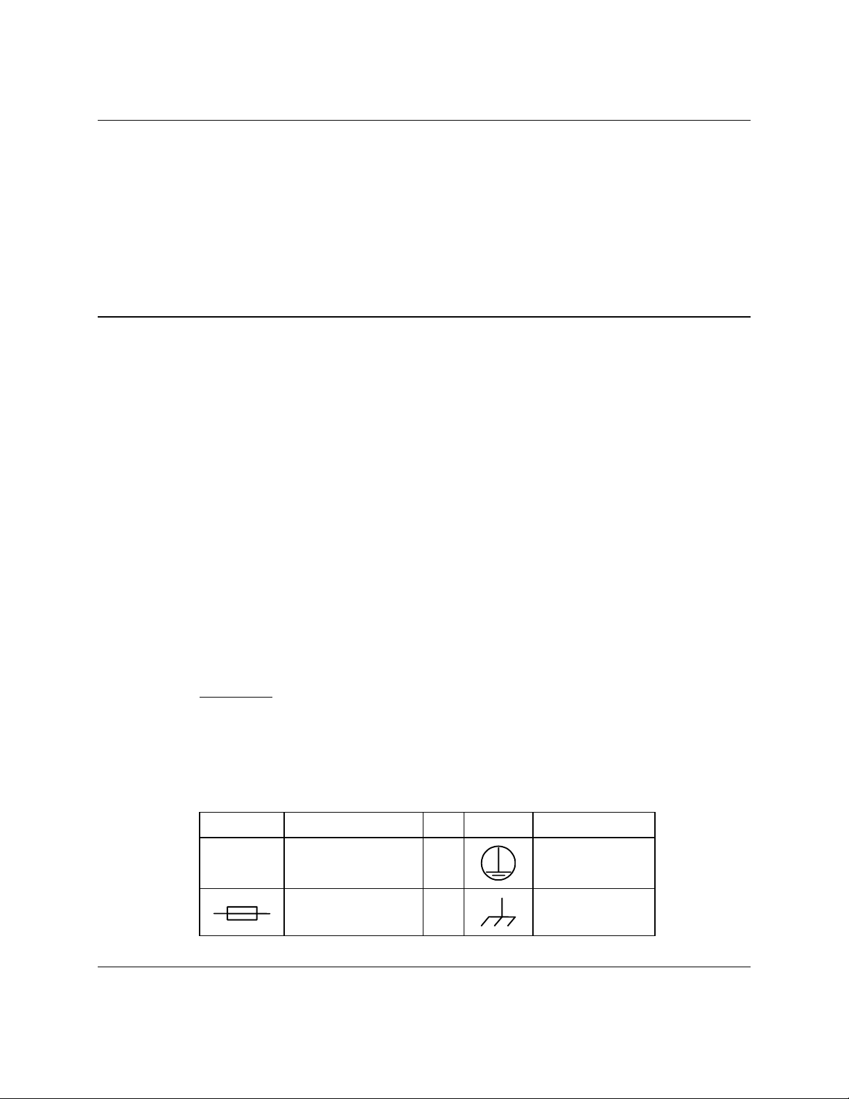
International Symbols:
Symbol Definition Symbol Definition
~
Alternating Current
Fuse
Telecommunications Terminal Equipment Directive
v
Protective Earth
Chassis Ground
Page 8

Breakout Panel Revision 2
Preface MN/UB530.IOM
In accordance with the Telecommunications Terminal Equipment Directive 91/263/EEC,
this equipment should not be directly connected to the Public Telecommunications
Network.
EMC (Electromagnetic Compatibility)
In accordance with European Directive 89/336/EEC, the breakout panel has been shown,
by independent testing, to comply with the following standards:
Emissions: EN 55022 Class B - Limits and methods of measurement of radio
interference characteristics of Information Technology Equipment.
(Also tested to FCC Part 15 Class B)
Immunity: EN 50082 Part 1 - Generic immunity standard, Part 1: Domestic,
commercial and light industrial environment.
Additionally, the breakout panel has been shown to comply with the following standards:
EN 61000-3-2 Harmonic Currents Emission
EN 61000-3-3 Voltage Fluctuations and Flicker
EN 61000-4-2 ESD Immunity
EN 61000-4-4 EFT Burst Immunity
EN 61000-4-5 Surge Immunity
EN 61000-4-6 RF Conducted Immunity
EN 61000-4-8 Power frequency Magnetic Field Immunity
EN 61000-4-9 Pulse Magnetic Field Immunity
EN 61000-4-11 Voltage Dips, Interruptions, and Variations Immunity
EN 61000-4-13 Immunity to Harmonics
In order that the breakout panel continues to comply with
these standards, observe the following instructions:
IMPORTANT
• Connections to the transmit and receive IF ports (Type N or Type F connectors)
should be made using a good quality coaxial cable - for example 50 Ω or 75 Ω.
• All 'D' type connectors attached to the rear panel must have back-shells that provide
continuous metallic shielding. Cable with a continuous outer shield (either foil or
braid, or both) must be used, and the shield must be bonded to the backshell.
• The equipment must be operated with its cover on at all times. If it becomes necessary
to remove the cover, the user should ensure that the cover is correctly re-fitted before
normal operation commences.
vi
Page 9
Breakout Panel Revision 2
Preface MN/UB530.IOM
Safety Compliance
EN 60950
This equipment meets the Safety of Information Technology Equipment specification as
defined in EN60950.
Low Voltage Directive (LVD)
The following information is applicable for the European Low Voltage Directive
(EN60950):
<HAR>
Type of power cord required for use in the European Community.
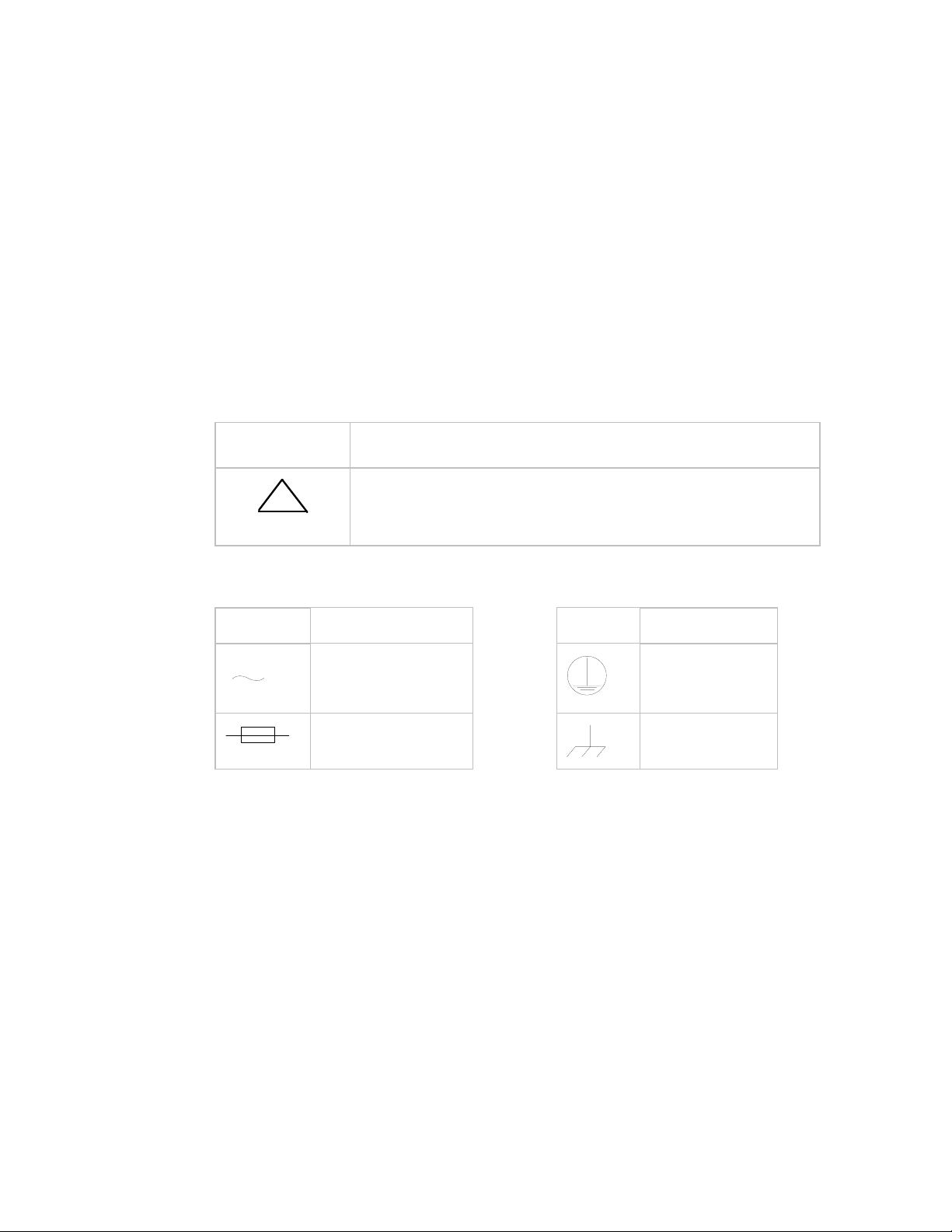
CAUTION: Double-pole/Neutral Fusing.
!
ACHTUNG: Zweipolige bzw. Neutralleiter-Sicherung.
International Symbols:
Symbol Definition Symbol Definition
Alternating Current.
Fuse.
Note: For additional symbols, refer to “Cautions” listed earlier in this preface.
Applicable testing is routinely performed as a condition of manufacturing on all units to
ensure compliance with safety requirements of EN60950.
Protective Earth.
Chassis Ground.
vii
Page 10

Breakout Panel Revision 2
Preface MN/UB530.IOM
Warranty Policy
This Comtech EF Data product is warranted against defects in material and workmanship
for a period of 12 months from the date of shipment. During the warranty period,
Comtech EF Data will, at its option, repair or replace products that prove to be defective.
For equipment under warranty, the customer is responsible for freight to Comtech EF
Data and all related custom, taxes, tariffs, insurance, etc. Comtech EF Data is responsible
for the freight charges only for return of the equipment from the factory to the customer.
Comtech EF Data will return the equipment by the same method (i.e., Air, Express,
Surface) as the equipment was sent to Comtech EF Data.
Limitations of Warranty
The foregoing warranty shall not apply to defects resulting from improper installation or
maintenance, abuse, unauthorized modification, or operation outside of environmental
specifications for the product, or, for damages that occur due to improper repackaging of
equipment for return to Comtech EF Data.
No other warranty is expressed or implied. Comtech EF Data specifically disclaims the
implied warranties of merchantability and fitness for particular purpose.
Exclusive Remedies
The remedies provided herein are the buyer's sole and exclusive remedies. Comtech EF
Data shall not be liable for any direct, indirect, special, incidental, or consequential
damages, whether based on contract, tort, or any other legal theory.
Disclaimer
Comtech EF Data has reviewed this manual thoroughly in order that it will be an easy-touse guide to your equipment. All statements, technical information, and
recommendations in this manual and in any guides or related documents are believed
reliable, but the accuracy and completeness thereof are not guaranteed or warranted, and
they are not intended to be, nor should they be understood to be, representations or
warranties concerning the products described. Further, Comtech EF Data reserves the
right to make changes in the specifications of the products described in this manual at any
time without notice and without obligation to notify any person of such changes.
If you have any questions regarding your equipment or the information in this manual,
please contact the Comtech EF Data Customer Support Department.
viii
Page 11

Chapter 1. Introduction
The UB-530 (Figure 1-1) provides industry standard interface connectors for access to the
modem’s data, clock, control, and alarm signals via a 50-pin D-sub connector. It functions
as a universal breakout panel for IDR, IBS, or D&I operations all in one, rack-mountable
unit.
Figure 1-1. UB-530 Breakout Panel
This breakout panel can be used in 1:1 switching configurations.
Major UB-530 features include:
• Convenient access to the SDM-308 Rev. 4 ESC through a standard 25-pin D
connector.
• Access to the 1/15 IBS overhead order wire, alarms, T1/E1, RS-422/449, and
V.35 data interfaces. The T1/E1 can be configured for balanced or unbalanced
DATA I/O signals through rear panel switches.
• Standardized interfaces for D&I data. Both balanced and unbalanced interfaces
for drop DATA I/O and insert DATA I/O are provided, and are selectable
through rear panel DIP switches.
• Standard 25-pin D connector pinout for V.35 or RS-530 signals
• Standard 37-pin D connector for RS-422 signals (RS-449 compatable).
1–1
Page 12

Breakout Panel Revision 1
Introduction MN/UB530.IOM
The UB-530 is a standard one unit (1U) rack-mountable chassis.The unit consists of a
printed circuit board, connectors, and switches for breakout panel operation. The
connectors and switches are located at the front and rear panels.
The UB-530 consists of the following assemblies:
Assembly Part #
Chassis PL/5809
Printed Circuit Board PL/5808
The electrical specifications for the UB-530 meet or exceed the electrical requirements of
the interfacing modem.
Refer to Chapter 2 for connector and switch information.
1–2
Page 13

Chapter 2. Connectors and
Switches
Connections between the breakout panel and other equipment are made through front and
rear panel connectors. Refer to Figure 2-1 for an illustration of the UB-530.
Figure 2-1. UB-530 Front and Rear Views
2–1
Page 14

Breakout Panel Revision 2
Connectors and Switches MN/UB530.IOM
2.1 Switches
The five configuration DIP switches located on the rear of the breakout panel are used for
selecting IBS/IDR modes of operation, and balanced or unbalanced signals, and control
of D&I looping.
The RS-422 multi-functional connector (J2) on the front panel may be used for standard
(non-overhead), IBS, or IDR (ESC) mode. SW1, SW2, and SW3 are used in selecting
IBS or IDR mode of operation.
SW4 and SW5 are used to select balanced or unbalanced inputs and outputs.
Refer to Table 2-1 for UB-530 configuration switch settings. The locations of the
switches are shown in Figure 2-1.
Table 2-1. UB-530 Configuration Switch Selections
Switch ON (Down) Position OFF (Up) Position
SW1-All IBS IDR
SW2-All IDR IBS
SW3-All IBS IDR
SW4-All Unbalanced Data & Clock Balanced Data & Clock
SW5-1 Unbalanced EXT Clock Balanced EXT Clock
SW5-2 Unbalanced EXT Clock Balanced EXT Clock
SW5-3 Drop out/Insert in loop Drop out/Insert in normal
SW5-4 Drop out/Insert in loop Drop out/Insert in normal
2.2 Connectors
The locations of the connectors are shown in Figure 2-1. Refer to Table 2-2 for a list of
UB-530 connectors.
Table 2-2. UB-530 Breakout Panel Connectors
Ref. Desig. Type Interface Function
J1 50-pin D socket Modem DATA I/O
J2 37-pin D socket RS-422 or 8 kbps ESC (IDR)
J3 25-pin D socket V.35 or RS-530
J4 25-pin D socket ESC
J5 25-pin D socket Alarms (IBS and IDR)
J6 9-pin D socket ADPCM Audio
J7 BNC Unbalanced Drop Data Input/SD
J8 BNC Unbalanced Insert Data Output/RD
J9 BNC Unbalanced Drop Data Output
J10 BNC Unbalanced Inset Data Input
J11 BNC Unbalanced External Clock
J12 15-pin D socket Balanced G.703
2–2
Page 15

Breakout Panel Revision 2
Connectors and Switches MN/UB530.IOM
2.2.1 Modem Data I/O (J1)
The modem data I/O connection is a 50-pin D connector located at the rear of the
breakout panel. Screw locks are provided for mechanical security of the mating
connector.
This connector is used to interface all signals to and from the modem. The type of signal
will depend on the configuration of the modem and panel. The UB-530 supports the
following configuration types and interface signals:
• IBS
• IDR
• D&I
• G.703
• V.35
• RS-422
• RS-232
• ASYNC
• Flex MUX
2–3
Page 16

Breakout Panel Revision 2
Connectors and Switches MN/UB530.IOM
2.2.1.1 IBS Interface (J1)
Signal Function Name Pin #
Ground GND 1, 2
External clock EXC–A 35
EXC–B 19
Serial clock TX SCT/ST–A 21
SCT/ST–B 22
ESC terrestrial TX data ESC TXD–A 5
ESC TXD–B 4
Send data SD–A 37
SD–B 38
T1E1 send data T1E1 SD–A 34
T1E1 SD–B 18
ESC terrestrial RX data ESC RXD–A 7
ESC RXD–B 6
Receive data RD–A 39
RD–B 40
T1E1 receive data T1E1 RD–A 36
T1E1 RD–B 20
Serial clock RX SCR/RT–A 23
SCR/RT–B 24
RS-422 RX octet RS422 RXO–A 8
RS422 RXO–B 9
Data set ready DSR/DM–A 41
DSR/DM–B 48
Primary alarm PRI–C 10
PRI–NO 43
PRI–NC 27
Secondary alarm SEC–C 11
SEC–NO 44
SEC–NC 28
Serial clock RX SCTE/TT–A 12
SCTE/TT–B 13
Request to send RTS–A 45
RTS–B 29
RX line signal detect RLSD/RR–A 46
Receiver ready RR–B 30
RS-422 TX octet RS-422 TXO–A 14
RS-422 TXO–B 15
Clear to send CTS–A 47
CTS–B 31
Data mode DM–B 32
2–4
Page 17

Breakout Panel Revision 2
Connectors and Switches MN/UB530.IOM
2.2.1.2 IDR Interface (J1)
Signal Function Name Pin #
Ground GND 1, 2
TX octet output 8K TXO–A 4
8K TXO–B 5
TX data 8K TXD–A 37
8K TXD–B 38
TX clock 8K TXC–A 21
8K TXC–B 22
RX octet 8K RXO–A 6
8K RXO–B 7
RX data 8K RXD–A 39
8K RXD–B 40
RX clock 8K RXC–A 23
8K RXC–B 24
Send data SD–A 34
SD–B 18
Receive data RD–A
RD–B
External clock EXC–A 35
EXC–B 19
Backward alarm 1 output BWO1–C 8
BWO1–NO 41
BWO1–NC 25
Backward alarm 2 output BWO2–C 9
BWO2–NO 42
BWO2–NC 26
Backward alarm 3 output BWO3–C 10
BWO3–NO 43
BWO3–NC 27
Backward alarm 4 output BWO4–C 11
BWO4–NO 44
BWO4–NC 28
Backward alarm input BWI–1 12
BWI–2 13
BWI–3 14
BWI–4 15
ADPCM1 audio input A1I–A 45
A1I–B 29
ADPCM1 audio output A1O–A 46
A1O–B 30
ADPCM2 audio input A2I–A 47
A2I–B 31
ADPCM2 audio output A2O–A 48
A2O–B 32
Demodulator fault DF–COM 16
DF–NO 50
Deferred maintenance alarm DMA 17
36
20
2–5
Page 18

Breakout Panel Revision 2
Connectors and Switches MN/UB530.IOM
2.2.1.3 D&I Interface (J1)
Signal Function Name Pin #
Ground GND 1, 2
Drop data input DDI–A 34
DDI–B 18
External clock EXC–A 35
EXC–B 19
Insert data output IDO–A 36
IDO–B 20
Drop data output DDO–A 37
DDO–B 38
Insert data input IDI–A 39
IDI–B 40
Terrestrial TX data TER–TXDAT 5
Terrestrial RX data TER–RXDAT 7
Primary PRI–COM 10
PRI–NO 43
PRI–NC 27
Secondary SEC–COM 11
SEC–NO 44
SEC–NC 28
Data set ready DSR 48
2–6
Page 19

Breakout Panel Revision 2
Connectors and Switches MN/UB530.IOM
2.2.2 RS-422 (IBS) or 8 kbps ESC (IDR) (J2)
The RS-422 or 8 kbps ESC (IDR) connection is a 37-pin D connector located at the front
of the breakout panel. Screw locks are provided for mechanical security of the mating
connector.
connection will operate as either an IBS (standard RS-422) or an IDR (8-kbps ESC)
The
I/O, depending on the configuration switch settings on the rear panel (see Section 2.1).
2.2.2.1 IBS/RS-422 (J2)
Signal Function Name Pin #
Ground GND 1, 19, 20, 37
TX octet TXO–A 3
TXO–B 21
Send data SD–A 4
SD–B 22
Send timing ST–A 5
ST–B 23
Receive data RD–A 6
RD–B 24
Request to send RTS–A 7
RTS–B 25
Receive timing RT–A 8
RT–B 26
Clear to send CTS–A 9
CTS–B 27
Data mode DM–A 11
DM–B 29
Receiver ready RR–A 13
RR–B 31
External clock EXC–A 15
EXC–B 33
RX octet RXO–A 16
RXO–B 34
Terminal timing TT–A 17
TT–B 35
2–7
Page 20

Breakout Panel Revision 2
Connectors and Switches MN/UB530.IOM
2.2.2.2 IDR 8-kbps ESC (J2)
Signal Function Name Pin #
Ground GND 1, 19, 20, 37
TX octet TXO–A 3
TXO–B 21
TX data TXD–A 4
TXD–B 22
TX clock TXC–A 5
TXC–B 23
RX data RXD–A 6
RXD–B 24
Request to send/ RTS–CTS–A 7, 9
Clear to send (see note) RTS–CTS–B 25, 27
RX clock RXC–A 8
RXC–B 26
RX octet RXO–A 15
RXO–B 33
Note: RTS/CTS lines are looped together at the connector
2.2.3 V.35, RS-530 (J3)
The V.35 connection is a 25-pin D connector located at the front of the breakout panel.
Screw locks are provided for mechanical security of the mating connector.
V.35 RS-530
Signal Function Name Pin # Name Pin #
Ground GND 1, 7 GND 1,7
Send data SD–A 2 SD–A 2
SD–B 14 SD–B 14
Serial clock TX SCT–A 15 ST-A 15
SCT–B 12 ST-B 12
Receive data RD–A 3 RD–A 3
RD–B 16 RD–B 16
Request to send RTS 4 RS-A
Serial clock RX SCR–A 17 RT-A 17
SCR–B 9 RT-B 9
Clear to send CTS 5 CS-A
Data set ready DSR 6 DM-A
RX line signal detect RLSD 8 RLSD-A
External data clock EXC–A 20 MC-A 20
EXC–B 23 MC-B 23
Serial clock TX external SCTE–A 24 TT-A 24
SCTE–B 11 TT-B 11
Modulator Fault MF 25 MF 25
Demodulator Fault DF 21 DF 21
RS-B
CS-B
DM-B
RLSD-B
4
19
5
13
6
22
8
10
2–8
Page 21

Breakout Panel Revision 2
Connectors and Switches MN/UB530.IOM
2.2.3.1 Adapting the V.35 25-Pin D Connector on the UB-530 to the
UB-300 Pinout
The connectors on the UB-530 and UB-300 Universal Breakout Panels are identically
wired, except for the 25-pin D connector which, is used for the V.35 data interface. The
UB-530 uses a standard RS-530 pinout, while the UB-300 pinout is non-standard. The
following information describes how to adapt the UB-530 to the UB-300 pinout.
An adapter is added to the UB-530 breakout panel that converts to the UB-300 pinout.
Figure 2-2 illustrates the adapter that plugs directly into J3 of the UB-530, and
Table 2-3 provides the wiring information for conversion from RS-530 to the UB-300
pinout.
To
Equipment
25 Pin D Female
Connector With
UB-300 Pinout
UB-530
To
UB-300
Adapter
Male Connector
Plugs Into
UB-530 Interface
UB-530
J3
25 Pin D Connector
For V.35 Interface
Figure 2-2. UB-530 To UB-300 Adapter For 25-Pin V.35 Connector (J3)
These adapters are available from several sources. The ones listed below are solder-less
and make conversion quick and easy:
Nomenclature Web Site Model/Part No.
Patton Electronics Company
(tel: 301 975 1000),
B&B Electronics (tel: 815 433 5100), ( http://www.bb-elec.com ): 232SMFJB
( http://ww.patton.com ): Model 8X-MF
2–9
Page 22

Breakout Panel Revision 2
Connectors and Switches MN/UB530.IOM
Table 2-3. Adapter Pinout For UB-530 To UB-300 Connection
25-Pin D Connector
Pin # V.35 (RS-530) To Pin # V.35 (UB-300) Notes
1 SHLD 1 SHLD
2 SD-A 14 SD-A
3 RD-A 16 RD-A
4 RTS-A 4 RTS
5 CTS-A 5 CTS
6 DSR-A 6 DSR
7 SIGGND 7 SIGGND
8 RLSD-A 8 RLSD
9 SCR-B 17 SCR-B
10 RLSD-B 10 1
11 SCTE-B 24 SCTE-B
12 SCT-B 15 SCT-B
13 CTS-B 13 1
14 SD-B 2 SD-B
15 SCT-A 18 SCT-A
16 RD-B 3 RD-B
17 SCR-A 19 SCR-A
18 11
19 RTS-B 9 1
20 MC-A 22 MC-A (EXC-A) 2
21 DF 21 DF 3
22 DSR-B 12 1
23 MC-B 23 MC-B (EXC-B) 2
24 SCTE-A 25 SCTE-A
25 MF 20 MF 3
Notes:
1. These signals are used for RS-530 (RS-422) and not required for V.35 which
uses only the “A” side of the signals.
2. Use the MASTER (MC or EXC) clock for EXTERNAL clock input. This clock
input should equal the data rate unless the Asymmetrical Loop Timing Option
(ASLT) is available. The ASLT option allows selection of different clock rates
that vary from the digital data rate. Refer to the Utility/Modem Type/Modem
Options menu for the ASLT option information.
3. MF and DF are fault indication signals from the modem and are not V.35 or
RS-530 standard signals.
2–10
Page 23

Breakout Panel Revision 2
Connectors and Switches MN/UB530.IOM
2.2.4 Engineering Service Channel (J4)
The Engineering Service Channel (ESC) connection is a 25-pin D connector located at the
front of the breakout panel. Screw locks are provided for mechanical security of the mating
connector.
Signal Function Name Pin #
Ground GND 1, 7
Transmit data TXD–A 2
TXD–B 14
Transmit clock TXCLK 15
Receive data RXD–A 3
RXD–B 16
Request to send/ RTS/CTS 4, 5
Clear to send (see note)
Receive clock RXCLK 17
Terrestrial ESC DSR TERESESCDSR 6
Note: RTS/CTS lines are looped together at the connector.
2–11
Page 24

Breakout Panel Revision 2
Connectors and Switches MN/UB530.IOM
2.2.5 Alarms (J5)
The alarms connection is a 25-pin D connector located at the front of the breakout panel.
The alarms interface is used to provide FORM C contact closures for the purpose of alarm
reporting. FORM C contacts ratings are:
• 1A at 24 VDC
• 500 mA at 120 VAC
A connection between the Common (C) and the Normally Open (NO) contacts indicates no
fault. The alarms interface will operate either in an IBS or an IDR mode, depending on the
configuration switch settings on the rear panel (see Section 2.1).
2.2.5.1 IBS Alarms (J5)
Signal Function Name Pin #
Ground GND 14
Primary alarm PRI–C 5
PRI–NO 18
PRI–NC 6
Secondary alarm SEC–C 19
SEC–NO 7
SEC–NC 20
2.2.5.2 IDR Alarms (J5)
Signal Function Name Pin #
Ground GND 14
Backward alarm 1 output BWO1–C 2
BWO1–NO 15
BWO1–NC 3
Backward alarm 2 output BWO2–C 16
BWO2–NO 4
BWO2–NC 17
Backward alarm 3 output BWO3–C 5
BWO3–NO 18
BWO3–NC 6
Backward alarm 4 output BWO4–C 19
BWO4–NO 7
BWO4–NC 20
Demodulator fault DF–COM 8
DF–NO 21
Deferred maintenance alarm DMA 9
Backward alarm 1 input BWI–1 22
Backward alarm 2 input BWI–2 10
Backward alarm 3 input BWI–3 23
Backward alarm 4 input BWI–4 11
2–12
Page 25

Breakout Panel Revision 2
Connectors and Switches MN/UB530.IOM
2.2.6 ADPCM Audio (J6)
The ADPCM audio connection is a 9-pin D connector located at the front of the breakout
panel. Screw locks are provided for mechanical security of the mating connector.
Audio
Signal Function
Ground GND 3 Ground
ADPCM1 audio input A1I–A 1 SDA (IN)
A1I–B 6 SDB (IN)
ADPCM1 audio output A1O–A 2 RTA (OUT)
A1O–B 7 RTB (OUT)
ADPCM2 audio input A2I–A 8 STA (OUT)
A2I–B 4 STB (OUT)
ADPCM2 audio output A2O–A 9 RDA (OUT)
A2O–B 5 RDB (OUT)
Name Pin #
64k Data
(RS422)
2.2.7 Drop Data Input/Send Data (J7)
The connection for the unbalanced drop data input/send data interface is a BNC connector
located at the front of the breakout panel. For unbalanced operation, the configuration
switches on the rear of the panel must be set correctly (see Section 2.1).
2.2.8 Insert Data Output/Receive Data (J8)
The connection for the unbalanced insert data output/receive data interface is a BNC
connector located at the front of the breakout panel. For unbalanced operation, the
configuration switches on the rear of the panel must be set correctly (see Section 2.1).
2.2.9 Drop Data Output (J9)
The connection for the unbalanced drop data output interface is a BNC connector located at
the front of the breakout panel. For unbalanced operation, the configuration switches on the
rear of the panel must be set correctly (see Section 2.1).
2.2.10 Insert Data Input (J10)
The connection for the unbalanced insert data input interface is a BNC connector located at
the front of the breakout panel. For unbalanced operation, the configuration switches on the
rear of the panel must be set correctly (see Section 2.1).
2–13
Page 26

Breakout Panel Revision 2
Connectors and Switches MN/UB530.IOM
2.2.10 External Clock (J11)
The connection for the unbalanced external clock interface is a BNC connector located at
the front of the breakout panel. This connection is used for clocking data out of the buffer.
For unbalanced operation, the configuration switches on the rear of the panel must be set
correctly (see Section 2.1).
2.2.11 Balanced G.703 Interface (J12)
The connection for the balanced G.703 interface is a 15-pin socket D connector located at
the front of the breakout panel. Screw locks are provided for the mechanical security of the
mating connector. For balanced operation, the configuration switches on the rear of the
panel must be set correctly (see Section 2.1).
Signal Function Name Pin #
Ground GND 2, 4
Drop data input/SD DDI–A 1
DDI–B 9
Insert data output/RD IDO–A 3
IDO–B 11
Drop data output DDO–A 12
DDO–B 5
Insert data input IDI–A 13
IDI–B 6
External clock EXC–A 7
EXC–B 8
2–14
Page 27

METRIC CONVERSIONS
Units of Length
Unit
1 centimeter — 0.3937 0.03281 0.01094
1 inch 2.540 — 0.08333 0.2778
1 foot 30.480 12.0 — 0.3333
1 yard 91.44 36.0 3.0 —
Centimeter
Inch
Foot
Yard
Mile
6.214 x 10
1.578 x 10
1.893 x 10
5.679 x 10
Meter
-6
-5
-4
-4
0.01 — —
0.254 — 25.4
0.3048 — —
0.9144 — —
Kilometer Millimeter
1 meter 100.0 39.37 3.281 1.094
1 mile
1 mm — 0.03937 — — — — — —
1 kilometer — — — — 0.621 — — —
1.609 x 10
5
6.336 x 10⁴ 5.280 x 10³ 1.760 x 10³
6.214 x 10
-4
—
— — —
1.609 x 10³
1.609 —
Temperature Conversions
Unit
32° Fahrenheit
212° Fahrenheit
-459.6° Fahrenheit
° Fahrenheit
—
—
—
° Centigrade
0
(water freezes)
100
(water boils)
273.1
(absolute 0)
Formulas
C = (F - 32) * 0.555
F = (C * 1.8) + 32
Units of Weight
Unit
1 gram — 0.03527 0.03215 0.002205 0.002679 0.001
Gram
Ounce
Avoirdupois
Ounce
Troy
Pound
Avoir.
Pound
Troy
Kilogram
1 oz. avoir. 28.35 — 0.9115 0.0625 0.07595 0.02835
1 oz. troy 31.10 1.097 — 0.06857 0.08333 0.03110
1 lb. avoir. 453.6 16.0 14.58 — 1.215 0.4536
1 lb. Troy 373.2 13.17 12.0 0.8229 — 0.3732
1 kilogram
1.0 x 10
3
35.27 32.15 2.205 2.679 —
Page 28

2114 WEST 7TH STREET TEMPE ARIZONA 85281 USA
480 • 333 • 2200 PHONE
480 • 333 • 2161
FAX
 Loading...