

Page 1

®
turbo
TCP/IP Performance Enhancement Proxy
Installation and Operation Manual
IMPORTANT NOTE: The information contained in this document supersedes all previously published
information regarding this product. Product specifications are subject to change without prior notice.
IP
For Software Version 5.1.2 or Higher
Part Number CD-TURBOIP-G2 Revision 2
-G2
Page 2

Page 3

®
turbo
TCP/IP Performance Enhancement Proxy
Installation and Operation Manual
IP
For Software Version 5.1.2 or Higher
Part Number CD-TURBOIP-G2
-G2
Revision 2
August 9, 2011
Comtech EF Data, 2114 West 7th Street, Tempe, Arizona 85281 USA, 480.333.2200, FAX: 480.333.2161
Copyright © Comtech EF Data, 2011. All rights reserved. Printed in the USA.
Page 4

This page is intentionally blank.
Page 5

TABLE OF CONTENTS
TABLE OF CONTENTS ................................................................................................. III
FIGURES ..................................................................................................................... VIII
PREFACE ...................................................................................................................... IX
About this Manual ....................................................................................................................... ix
Reporting Comments or Suggestions Concerning this Manual ................................................. ix
Conventions and References ....................................................................................................... ix
Warnings, Cautions, and Notes .................................................................................................. ix
Metric Conversion ...................................................................................................................... x
Recommended Standard Designations ....................................................................................... x
Trademarks ................................................................................................................................. x
Safety Compliance ........................................................................................................................ x
EN 60950 Electrical Safety and Compliance .............................................................................. x
European Low Voltage Directive (LVD) (2006/95/EC) ............................................................ x
Electromagnetic Compatibility (EMC) Compliance ................................................................ xi
EN 55022 – 1997 Compliance ................................................................................................... xi
EN 50082-1 – 1997 Compliance ................................................................................................ xi
Federal Communications Commission (FCC) ........................................................................... xi
End User License Agreement (EULA) ...................................................................................... xii
End User License Agreement (EULA) Copy Protection ........................................................ xvi
Warranty Policy ........................................................................................................................ xvii
Limitations of Warranty .......................................................................................................... xvii
Exclusive Remedies ............................................................................................................... xviii
Customer Support ...................................................................................................................... xix
Contact Comtech EF Data for: ................................................................................................. xix
Contacting Comtech EF Data .................................................................................................. xix
Returning a Product for Upgrade or Repair .............................................................................. xx
CHAPTER 1. INTRODUCTION ................................................................................ 1–1
iii
Page 6

turboIP-G2 Performance Enhancement Proxy Revision 2
Table of Contents CD-TURBOIP-G2
1.1 Overview ........................................................................................................................ 1–1
1.1.1 Key Operational Features ........................................................................................... 1–2
1.2 Features .......................................................................................................................... 1–3
1.2.1 Physical Description ................................................................................................... 1–3
1.2.1.1 Major Assemblies (Standard and Optional) ........................................................ 1–3
1.2.2 Dimensional Envelopes .............................................................................................. 1–4
1.2.3 Physical Features ........................................................................................................ 1–7
1.2.3.1 Front Panels ........................................................................................................ 1–7
1.2.3.2 Rear Panels.......................................................................................................... 1–8
1.2.4 Acceleration and WAN Optimization ......................................................................... 1–9
1.2.4.1 TCP/IP Performance Limitations ........................................................................ 1–9
1.2.4.2 TCP/IP Performance Enhancement Proxy ........................................................ 1–10
1.2.4.3 Selective Acceleration ...................................................................................... 1–11
1.2.4.4 Data and Header Compression .......................................................................... 1–12
1.2.4.5 Minimum Compression Ratio ........................................................................... 1–12
1.3 Software Update .......................................................................................................... 1–12
1.4 FAST System ............................................................................................................... 1–13
1.4.1 FAST System Theory ............................................................................................... 1–13
1.4.2 FAST Implementation .............................................................................................. 1–13
1.4.3 FAST Accessible Options ......................................................................................... 1–13
1.5 Remote Control ........................................................................................................... 1–14
1.6 Summary of Specifications ......................................................................................... 1–14
CHAPTER 2. INSTALLATION AND STARTUP ...................................................... 2–1
2.1 Unpacking and Inspection ............................................................................................ 2–1
2.2 Rack Mounting the turboIP-G2 ................................................................................... 2–2
2.2.1 Rack Mounting – Full-Width turboIP-G2 Configuration ........................................... 2–3
2.2.2 1/2-Width turboI P - G 2 – R a c k M o u n t i n g C o n f i g u r a t i o n s u s i n g K i t P P - 0 0 0 0 0 4 9 .................. 2–4
2.2.2.1 1/2-Width turboIP-G2 – Single Unit Rack Mount Configuration ...................... 2–5
2.2.2.2 1/2-Width turboIP - G 2 – D u a l Rack Mount Configuration ..................................... 2–6
2.3 turboIP-G2 Cabling and Star t up .................................................................................. 2–8
CHAPTER 3. REAR PANEL CONNECTORS ......................................................... 3–1
3.1 Connectors Overview.................................................................................................... 3–1
3.2 Console Connector (DB-9F) ......................................................................................... 3–2
3.3 10/100/1000 BaseT Ethernet LAN / WAN Ports (2X RJ-45) .................................... 3–2
iv
Page 7

turboIP-G2 Performance Enhancement Proxy Revision 2
Table of Contents CD-TURBOIP-G2
3.4 10/100/1000 BaseT Ethernet MGT Port (1X RJ-45) .................................................. 3–3
3.5 IEC Line Input (AC Power) Connector ...................................................................... 3–3
CHAPTER 4. CONFIGURATION AND UPDATING ................................................. 4–1
4.1 Important Configuration Notes ................................................................................... 4–1
4.2 Required Equipment .................................................................................................... 4–2
4.3 User Interfaces .............................................................................................................. 4–2
4.3.1 CONSOLE Settings .................................................................................................... 4–3
4.4 End User License Agreement (EULA) ........................................................................ 4–3
4.4.1 End User License Agreement (EULA) Copy Protection ............................................ 4–4
4.5 turboIP-G2 Configuration Wizard .............................................................................. 4–5
4.5.1 Configuration Wizard – Operational Overview .......................................................... 4–5
4.5.1.1 User Accounts / Username .................................................................................. 4–7
4.5.1.2 Password ............................................................................................................. 4–8
4.5.1.3 UTC (Coordinated Universal Time) Settings ..................................................... 4–9
4.5.1.4 DOD Warning Banner ...................................................................................... 4–11
4.6 Updating turboIP-G2 Software .................................................................................. 4–12
4.6.1 Preparing for the Software Update ........................................................................... 4–12
4.6.1.1 Verifying Communications between the User PC and CLI .............................. 4–12
4.6.1.2 Identifying the Software Version and Management IP Address ...................... 4–13
4.6.1.2.1 Identification Using the CLI ....................................................................... 4–13
4.6.1.2.2 Identification Using the Web Server Graphical User Interface (GUI) ........ 4–14
4.6.1.3 Creating and Renaming a Temporary Folder (for the Software Archive
Download) on the User PC. .............................................................................................. 4–15
4.6.1.4 Downloading the Archived Software Update File ............................................ 4–17
4.6.2 Updating Software .................................................................................................... 4–20
4.6.2.1 Updating via the Command Line Interface (CLI) ............................................. 4–20
4.6.2.2 Updating via the Web Server Graphical User Interface (GUI) ......................... 4–22
4.6.2.2.1 FTP UPDATE via the Web Server GUI ..................................................... 4–23
4.6.2.2.2 UPLOAD UPDATE via the Web Server GUI ............................................ 4–25
4.6.2.2.3 Troubleshooting the Software Update Process ........................................... 4–26
CHAPTER 5. MANAGEMENT VIA THE CLI OR WEB SERVER GUI ..................... 5–1
5.1 Important Interface Operation Notes ......................................................................... 5–1
5.2 Command Line Interface (CLI) .................................................................................. 5–2
5.2.1 CLI Login.................................................................................................................... 5–2
5.2.2 CLI Operation using the SSH (Secure Shell) Interface .............................................. 5–3
5.2.2.1 Common Operational Features ........................................................................... 5–4
v
Page 8

turboIP-G2 Performance Enhancement Proxy Revision 2
Table of Contents CD-TURBOIP-G2
5.2.3 CLI Main Menu Screen .............................................................................................. 5–4
5.2.3.1 Configure Interfaces Screen ................................................................................ 5–6
5.2.3.1.1 Configure Interfaces | Management IP Address Configuration Screen ........ 5–7
5.2.3.1.2 Configure Interfaces | Link Setting Configuration Screen ............................ 5–8
5.2.3.1.3 Configure Interfaces | Advanced Options Screen ......................................... 5–9
5.2.3.2 Gateway Configuration Screen ......................................................................... 5–10
5.2.3.2.1 WAN Transmission Rate ............................................................................ 5–11
5.2.3.2.2 Maximum Transfer Unit (MTU) ................................................................. 5–11
5.2.3.2.3 Congestion Control ..................................................................................... 5–11
5.2.3.3 Routing Screen .................................................................................................. 5–13
5.2.3.3.1 Routing | IPv4 Routing Table Screen .......................................................... 5–13
5.2.3.3.2 Routing | IPv6 Routing Table Screen .......................................................... 5–14
5.2.3.4 SNMP Screen .................................................................................................... 5–15
5.2.3.4.1 SNMP Configuration Wizard ...................................................................... 5–15
5.2.3.4.2 SNMP Screen (SNMP v2)........................................................................... 5–16
5.2.3.4.3 SNMP Screen (SNMP v3)........................................................................... 5–17
5.2.3.5 Optimization Screen .......................................................................................... 5–18
5.2.3.6 Selective Acceleration Screen ........................................................................... 5–19
5.2.3.6.1 Selective Acceleration | View/Edit Rules Screen ........................................ 5–20
5.2.3.6.1.1 Selective Acceleration | View/Edit Rules | Edit Rule Screen ............... 5–21
5.2.3.6.2 Selective Acceleration | Statistics Screen .................................................... 5–22
5.2.3.7 Administrative Functions Screen ...................................................................... 5–23
5.2.3.7.1 Administrative Functions | Configurations/Actions Screen ........................ 5–24
5.2.3.7.2 Administrative Functions | Event Log Configuration Screen ..................... 5–25
5.2.3.7.2.1 Administrative Functions | Event Log Configuration |View Log Screen 5–
26
5.2.3.7.3 Administrative Functions | Statistics Screen ............................................... 5–27
5.2.3.7.3.1 Administrative Functions | Save/Restore State Screen ........................ 5–28
5.2.3.8 Command Line Interface Screen ...................................................................... 5–29
5.2.3.8.1 Interface Overview ...................................................................................... 5–29
5.2.3.8.2 ‘get’ Query .................................................................................................. 5–30
5.2.3.8.3 ‘ip’ Command ............................................................................................. 5–32
5.2.3.8.4 ‘log’ Command ........................................................................................... 5–32
5.2.3.8.5 ‘ping’ Command ......................................................................................... 5–32
5.2.3.8.6 ‘route’ Command ........................................................................................ 5–33
5.2.3.8.7 ‘route6’ Command ...................................................................................... 5–33
5.2.3.8.8 ‘rule’ Command .......................................................................................... 5–33
5.2.3.8.9 ‘set’ Command ............................................................................................ 5–34
5.2.3.8.10 ‘snmp’ Command ...................................................................................... 5–36
5.2.3.8.11 ‘stats’ Command ....................................................................................... 5–36
5.2.3.8.12 ‘system’ Command ................................................................................... 5–36
5.2.3.8.13 ‘tcpdump’ Command ................................................................................. 5–37
5.2.3.8.14 ‘traceroute’ Command ............................................................................... 5–37
5.2.3.8.15 ‘user’ Command ........................................................................................ 5–37
5.3 Web Server (HTTP) Graphical User Interface (GUI) ............................................. 5–38
5.3.1 Web Server GUI Login ............................................................................................. 5–38
vi
Page 9

turboIP-G2 Performance Enhancement Proxy Revision 2
Table of Contents CD-TURBOIP-G2
5.3.2 Web Server GUI Pages ............................................................................................. 5–39
5.3.2.1 Acceleration Pages ............................................................................................ 5–41
5.3.2.1.1 Acceleration | Skipware Page ...................................................................... 5–41
5.3.2.1.2 Acceleration | Optimization Page ................................................................ 5–42
5.3.2.2 Interface Pages .................................................................................................. 5–43
5.3.2.2.1 Interface | Configuration Page ..................................................................... 5–43
5.3.2.2.2 Interface | Routes Page ................................................................................ 5–44
5.3.2.2.3 Interface | IPv6 Routes Page ....................................................................... 5–44
5.3.2.2.4 Interface | Advanced Page ........................................................................... 5–45
5.3.2.3 Graphs Page ...................................................................................................... 5–46
5.3.2.4 Selective Acceleration Pages ............................................................................ 5–47
5.3.2.4.1 Selective Acceleration | Rules Page ............................................................ 5–47
5.3.2.4.2 Selective Acceleration | Stats Page ............................................................. 5–48
5.3.2.5 Admin Pages ..................................................................................................... 5–49
5.3.2.5.1 Admin | Configuration Page ........................................................................ 5–49
5.3.2.5.2 Admin | Event Log Page ............................................................................. 5–50
5.3.2.5.3 Admin | Stats Page ...................................................................................... 5–51
CHAPTER 6. MANAGEMENT VIA SNMP ............................................................... 6–1
6.1 Overview ........................................................................................................................ 6–1
6.2 MIBII Support .............................................................................................................. 6–1
6.3 Private MIB Support .................................................................................................... 6–1
6.3.1 MIB Tree ..................................................................................................................... 6–2
6.3.2 turboIP-G2 Gateway Configuration ........................................................................... 6–5
6.3.3 turboIP-G2 Interface ................................................................................................... 6–6
6.3.4 turboIP-G2 Route ........................................................................................................ 6–9
6.3.5 turboIP-G2 Selective Acceleration ........................................................................... 6–11
6.3.6 turboIP-G2 QoS Statistics Table ............................................................................... 6–15
6.3.7 turboIP-G2 Admin .................................................................................................... 6–17
6.3.8 turboIP-G2 Admin Info ............................................................................................ 6–19
6.3.9 turboIP-G2 Event Log .............................................................................................. 6–20
6.3.10 turboIP-G2 Statistics ............................................................................................. 6–21
6.3.11 turboIP-G2 Fail To Wire ....................................................................................... 6–23
6.3.12 turboIP-G2 HTTP ................................................................................................. 6–23
6.3.13 turboIP-G2 Optimization Configuration ............................................................... 6–24
6.3.14 turboIP-G2 Notifications ...................................................................................... 6–29
6.3.15 turboIP-G2 Process Notifications ......................................................................... 6–30
CHAPTER 7. EASYCONNECT™ ............................................................................ 7–1
7.1 Introduction ................................................................................................................... 7–1
7.2 easyConnect™ ON ........................................................................................................ 7–1
vii
Page 10

turboIP-G2 Performance Enhancement Proxy Revision 2
Table of Contents CD-TURBOIP-G2
CHAPTER 8. FAIL TO WIRE ................................................................................... 8–1
8.1 Introduction ................................................................................................................... 8–1
8.2 Fail to Wire Board Operation ...................................................................................... 8–1
8.3 Fail to Wire Board Installed ........................................................................................ 8–2
APPENDIX A. SAMPLE CONFIGURATIONS ......................................................... A–1
A.1 Overview ....................................................................................................................... A–1
A.2 Point-to-Point Configuration ...................................................................................... A–2
A.3 Point-to-MultiPoint Configuration............................................................................. A–3
A.4 Hub-Spoke Configuration ........................................................................................... A–4
A.5 Dynamic Bandwidth Configuration ........................................................................... A–5
FIGURES
Figure 1-1. turboIP-G2 1/2-Width (top) and Full-Width 1RU Units (Chassis Only) ................ 1–1
Figure 1-2. turboIP-G2 Dimensional Envelope – Full-Width Chassis (Typical) ....................... 1–4
Figure 1-3. turboIP-G2 Dimensional Envelope – 1/2-Width Chassis (Single Unit Mount) ...... 1–5
Figure 1-4. turboIP-G2 Dimensional Envelope – 1/2-Width Chassis (Dual Unit Mount) ......... 1–6
Figure 1-5. turboIP-G2 Front Panels (Chassis Only) ................................................................. 1–7
Figure 1-6. turboIP-G2 Rear Panels (Chassis only) ................................................................... 1–8
Figure 2-1. Typical turboIP-G2 Full-Width and 1/2-Width Unit Rack Installations ................. 2–2
Figure 2-2. Full-Width Configuration – Universal Front Rack Bracket Installation .................. 2–3
Figure 2-3. PP-0000049 Rack Mount Kit ................................................................................... 2–4
Figure 2-4. 1/2-Width Rack Mount Kit Assembly – Single Unit Configuration........................ 2–5
Figure 2-5. 1/2-Width Rack Mount Kit Assembly – Dual Unit Configuration .......................... 2–7
Figure 2-6. Installation of Rack Mount Kit’s Bridge Clips / Docking the Units ........................ 2–7
Figure 2-7. Installation of Rack Mount Kit’s Chassis Link Rear Bracket .................................. 2–8
Figure 3-1. turboIP-G2 Rear Panels (Chassis only, prior to November 2010)........................... 3–1
Figure 3-2. turboIP-G2 Rear Panels (Chassis only, November 2010 and later) ......................... 3–1
Figure A-1. Point-to-Point Configuration .................................................................................. A–2
Figure A-2. Point-to-Multipoint Configuration ......................................................................... A–3
Figure A-3. Hub-Spoke Configuration ...................................................................................... A–4
Figure A-4. Dynamic Bandwidth Configuration ....................................................................... A–5
viii
Page 11
About this Manual
PREFACE
This manual provides installation and operation information for the Comtech EF Data turboIP-G2
Performance Enhancement Proxy device. This is a document intended for the persons responsible for
the operation and maintenance of the turboIP-G2.
Comtech EF Data reserves the right to change specifications of products described in this document
at any time without notice and without obligation to notify any person of such ch anges. Informatio n
in this document may differ from information published in other Comtech EF Data documents.
Refer to the company website or contact Customer Service for the latest released product
information.
Reporting Comments or Suggestions Concerning this Manual
Comments and suggestions regarding the content and design of this manual are appreciated. To
submit comments, please contact the Comtech EF Data Technical Publications department:
TechnicalPublications@comtechefdata.com
Conventions and References
Warnings, Cautions, and Notes
A WARNING gives information about a possible hazard that MAY CAUSE DEATH or
SERIOUS INJURY.
A CAUTION
PROPERTY DAMAGE.
A NOTE
A REFERENCE
gives information about a possible hazard that MAY CAUSE INJURY or
gives important information about a task or the equipment.
directs the user to additional information about a task or the equipment.
ix
Page 12
turboIP-G2 Performance Enhancement Proxy Revision 2
Preface CD-TURBOIP-G2
Metric Conversion
Metric conversion information is located on the inside back cover of this manual. This information
is provided to assist the operator in cross-referenc ing non-Metric to Metric conversions.
Recommended Standard Designations
Recommended Standard (RS) Designations have been superseded by the new designation of the
Electronic Industries Association (EIA). There may be reference to the old ‘RS’ designation (e.g.,
RS-232) when depicting actual text displayed on the turboIP-G2’s Web Server or CLI (Remote
Control) M&C interfaces. All other references use the EIA designation.
Trademarks
Product names mentioned in this manual may be trademarks or registered trademarks of their
respective companies and are hereby acknowledged.
Safety Compliance
EN 60950 Electrical Safety and Compliance
This equipment has been shown to comply with the EN 60950 Safety of Information Technology
Equipment (Including Electrical Business Machines) safety standard.
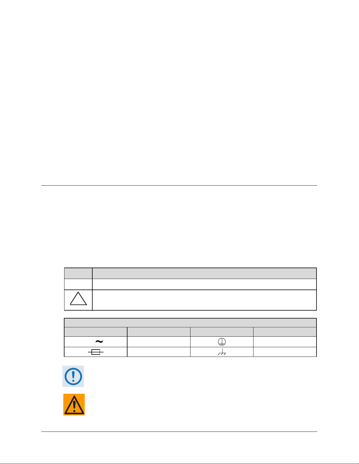
European Low Voltage Directive (LVD) (2006/95/EC)
Symbol Description
<HAR>
!
Type of power cord required for use in the European Community.
CAUTION: Double-pole/Neutral Fusing
ACHTUNG: Zweipolige bzw. Neutralleiter-Sicherung
International Symbols
Symbol Definition Symbol Definition
Alternating Current
Fuse
For additional symbols, refer to Cautions and Warnings listed earlier in this
Preface. Applicable testing is routinely performed as a condition of manufacturing
on all units to ensure compliance with safety requirements of EN 60950.
TO MAKE SURE THAT THE UNIT COMPLIES WITH THESE STANDARDS, OBEY
THESE INSTRUCTIONS:
Protective Earth
Chassis Ground
x
Page 13

turboIP-G2 Performance Enhancement Proxy Revision 2
Preface CD-TURBOIP-G2
• Use Type 'D' connectors that have back-shells with continuous metallic shielding.
• Type ‘D’ cabling must have a continuous outer shield (either foil or braid, or both). The
shield must be bonded to the back-shell.
• Operate the unit with its cover on at all times.
Electromagnetic Compatibility (EMC) Compliance
EN 55022 – 1997 Compliance
This equipment meets the radio disturbance characteristic specifications for information
technology equipment as defined in EN 55022 Limits and Methods of Measurement of Radio
Interference Characteristics of Information Technology Equipment.
EN 50082-1 – 1997 Compliance
This equipment meets the electromagnetic compatibility/generic immunity standard as defined in
EN 50082-1 Immunity Standards for Commercial Electronic Products.
Federal Communications Commission (FCC)
This equipment has been tested and found to comply with the limits for a Class A digital device,
pursuant to Part 15, Subpart B of the FCC rules. These limits are designed to provide reasonable
protection against harmful interference when the equipment is operated in a commercial
environment.
This equipment generates, uses, and can radiate radio frequency energy. If not installed and used in
accordance with the Installation and Operation Manual, operation of this equipment in a residential
area is likely to cause harmful interference that requires the user to take adequate protection
measures; in which case, users are required to correct the interference at their own expense.
xi
Page 14

turboIP-G2 Performance Enhancement Proxy Revision 2
Preface CD-TURBOIP-G2
End User License Agreement (EULA)
Upon successful login for the first time, the following End User License Agreement (EULA) is
displayed:
IMPORTANT - READ THESE TERMS CAREFULLY BEFORE USING THIS SOFTWARE.
BY CLICKING THE "ACCEPT" BOX AT THE END OF THIS PAGE AND USING THIS
SOFTWARE, YOU ACKNOWLEDGE THAT YOU HAVE READ THIS END USER
LICENSE AGREEMENT ("EULA"),THAT YOU UNDERSTAND IT, AND THAT YOU
AGREE TO BE BOUND BY ITS TERMS. IF YOU DO NOT AGREE TO THE TERMS AND
CONDITIONS OF THIS EULA, CLICK ON THE "DECLINE" BOX AT THE END OF THIS
PAGE AND THE SOFTWARE WILL NOT BE ACTIVATED.
IF YOU ARE EMPLOYEE OF A COMPANY AND/OR ARE ACTIVATING THIS
SOFTWARE AT THE REQUEST OF, AND FOR THE BENEFIT OF A THIRD PARTY,
THEN BY CLICKING BELOW YOU ACKNOWLEDGE AND REPRESENT THAT YOU
HAVE THE AUTHORITY TO ENTER INTO THIS AGREEMENT ON BEHALF OF YOUR
COMPANY OR THE THIRD PARTY FOR WHOM YOU ARE ACTIVATING THE
SOFTWARE, AND THAT THEY AGREE TO BE FULLY BOUND BY THE TERMS AND
CONDITIONS OF THIS EULA.
1. Grant of License for Registered Users
The SkipWare® version 4.5 software contained herein is provided to you through Comtech EF
Data Corporation ("CEFD"), for use exclusively with the CEFD turboIP-G2, modem or other
hardware product it accompanies. GLOBAL PROTOCOLS, Inc. ("GPI"), the owner of the
SkipWare software, grants you a non-exclusive, non-transferable license to use SkipWare version
4.0 only with the accompanying hardware. This license includes, but is not limited to the
SkipWare software version 4.5; any documentation files accompanying the software; and any online or electronic documentation (collectively, all of these things are "SkipWare"), provided that:
(i) SkipWare is used only with the accompanying CEFD turboIP-G2, modem or hardware
product; (ii) SkipWare is NOT modified; (iii) all copyright notices are maintained on SkipWare;
and (iv) you agree to be bound by the terms of this EULA. Any future software upgrades to this
4.5 version of SkipWare will be covered by either a "paid for" maintenance agreement with GPI
or as part of a "paid for" software upgrade. Software upgrades obtained from any source other
than CEFD or GPI, will be considered a license infringement, and will render your license to use
SkipWare® void.
2. Ownership
SkipWare is owned by GPI. You have no ownership rights in SkipWare, nor does this EULA
grant you any ownership rights. Rather, you have a license to use SkipWare as long as this EULA
remains in full force and effect. wnership of all intellectual property rights likewise remains at all
times with GPI. Any other use of SkipWare by any person, business, corporation, government
organization, or any other entity is strictly forbidden and is a violation of this EULA. Also any
unauthorized upgrades obtained other than from CEFD or GPI directly will be considered a
violation of this EULA.
xii
Page 15

turboIP-G2 Performance Enhancement Proxy Revision 2
Preface CD-TURBOIP-G2
3. Copyright
SkipWare contains material that is protected by the United States opyright Law, Patent Law and
trade secret law, and by international treaty provisions. This includes all programming, source
code, object code, titles, images, text, subroutines and applets, as applicable, incorporated into
SkipWare. All rights not granted to you herein are expressly and unconditionally reserved by
GPI. You may not remove any proprietary notice of GPI from any copy of SkipWare.
4. Restrictions
You may not publish, display, disclose, rent, lease, license, sublicense, modify, rename, loan,
distribute, or create derivative works based on SkipWare or any part thereof. You may not reverse
engineer, decompile, translate, adapt, or disassemble SkipWare, nor shall you attempt to create
the source code from the object code for SkipWare. You may not transmit SkipWare over any
network or between any devices, although you may use SkipWare to make such transmissions of
other materials. Also you may not upgrade SkipWare by any means, either over the web, through
changing flash memory or any other means, without the express permission of CEFD and GPI,
and you must contact and ultimately register with CEFD prior to upgrading SkipWare, and pay
for maintenance or any upgrade feed that is required. Any upgrades obtained through other than
CEFD or GPI will be considered pirated and will be a violation under this agreement.
5. Confidentiality
You acknowledge that SkipWare contains proprietary trade secrets of GPI and you hereby agree
to maintain the confidentiality of SkipWare using at least as great a degree of care as you use to
maintain the confidentiality of your own most confidential information, but in no event less than
reasonable care. You agree to reasonably communicate the terms and conditions of this SkipWare
EULA to those persons employed by you who come into contact with SkipWare, and to use your
best efforts to ensure their compliance with such terms and conditions, including, without
limitation, not knowingly permitting such persons to use any portion of SkipWare for the purpose
of deriving the source code of SkipWare.
6. No Warranty
SKIPWARE IS PROVIDED TO YOU "AS IS" AND ANY USE OF SKIPWAR E BY YOU IS
ENTIRELY AT YOUR OWN RISK. TO THE MAXIMUM EXTENT PERMITTED BY LAW,
GPI DISCLAIMS ALL WARRANTIES OF ANY KIND, EITHER EXPRESSED OR IMPLIED,
INCLUDING, WITHOUT LIMITATION, IMPLIED WARRANTIES OF MERCHANTABILITY
AND FITNESS FOR A PARTICULAR PURPOSE. GPI DOES NOT WARRANT THAT THE
FUNCTIONS CONTAINED IN SK IPWARE WILL MEET ANY REQUIREMENTS OR NEEDS
YOU MAY HAVE, OR THAT SKIPWARE WILL OPERATE ERROR FREE, OR IN AN
UNINTERRUPTED FASHION, OR THAT ANY DEFECTS OR ERRORS IN SKIPWARE WILL
BE CORRECTED, OR THAT SKIPWARE IS COMPATIBLE WITH ANY PARTICULAR
PLATFORM. SOME JURISDICTIONS DO NOT ALLOW THE WAIVER OR EXCLUSION OF
IMPLIED WARRANTIES SO THEY MAY NOT APPLY TO YOU.
xiii
Page 16

turboIP-G2 Performance Enhancement Proxy Revision 2
Preface CD-TURBOIP-G2
7. Limitation of Liability
IN NO EVENT WILL GPI BE LIABLE TO YOU OR ANY THIRD PARTY FOR ANY
INCIDENTAL OR CONSEQUENTIAL DAMAGES(INCLUDING, WITH OUT LIMITATION,
INDIRECT, SPECIAL, PUNITIVE, OR EXEMPLARY DAMAGES, INCLUDING FOR LOSS
OF BUSINESS, LOSS OF PROFITS, BUSINESS INTERRUPTION, OR LOSS OF BUSINESS
INFORMATION) ARISING OUT OF THE USE OF OR INABILITY TO U SE SKIPWARE,
OR FOR ANY CLAIM BY ANY OTHER PARTY, EVEN IF GPI HAS BE EN ADVISED OF
THE POSSIBILITY OF SUCH DAMAGES. GPI'S AGGREGATE LIABILITY WITH
RESPECT TO ITS OBLIGATIONS UNDER THIS EULA OR OTHERWISE WITH
RESPECT TO SKIPWARE OR OTHERWISE SHALL NOT EXCEED THE AMOUNT OF
THE LICENSE FEE PAID BY YOU TO GPI FOR SKIPWARE. BECAUSE SOME
STATES/COUNTRIES DO NOT ALLOW THE EXCLUSION OR LIMITATION OF
LIABILITY FOR CONSEQUENTIAL OR INCIDENTAL DAMAGES, THE ABOVE
LIMITATIONMAY NOT APPLY TO YOU.
GPI also shall have no liability for non-delivery or delay in delivery of products and services
arising from any event beyond its reasonable control, whether or not foreseeable by either party,
including but not limited to, war, acts of terrorism and events related to such acts, fire, flood,
accident, adverse weather, inability to secure transportation, insurrections, riots, or civil
commotions, strikes, lockouts, or other labor disturbances; acts of God; or acts, omissions, or
delays in acting by, or as a result of, any governmental authority, governmental act or regulation,
and other causes or events beyond GPI's reasonable control, whether or not similar to those which
are enumerated above.
8. Export Restrictions
THIS EULA IS EXPRESSLY MADE SUBJECT TO ANY LAWS, REGUL ATIONS, ORDE RS,
OR OTHER RESTRICTIONS ON THE EXPORT FROM THE UNITED STATES OF
AMERICA OF SKIPWARE OR INFORMATION ABOUT SUCH SKIPWARE, WHICH MAY
BE IMPOSED FROM TIME TO TIME BY THE GOVERNMENT OF THE UNITED STATES
OF AMERICA. YOU SHALL NOT EXPORT SKIPWARE, OR INFORMATION ABOUT
SKIPWARE, WITHOUT THE EXPRESS CONSENT OF GPI AND COMPLIANCE WITH
SUCH LAWS, REGULATIONS, ORDERS, OR OTHER RESTRICTIONS.
9. Termination
This EULA is effective for so long as you own and operate the CEFD turboIP-G2, modem or
other hardware product which SkipWare accompanies. You may terminate this EULA at any time
by destroying or returning to GPI all copies of SkipWare in your possession or under your
control. GPI may terminate this EULA for any reason, including, but not limited to, if GPI finds
that you have violated any of the terms or conditions of this EULA, including upgrading this
software from a source other than CEFD or GPI. Upon receiving notification of termination by
GPI, you agree to return to GPI all copies of SkipWare and to certify in writing that all known
copies, including backup copies, have been destroyed. All provisions relating to confidentiality,
proprietary rights, and non-disclosure shall survive the termination of this SkipWare EULA, and
termination will in no event affect any liability or obligation which arose prior thereto.
xiv
Page 17

turboIP-G2 Performance Enhancement Proxy Revision 2
Preface CD-TURBOIP-G2
10. Notice
All notices to CEFD shall be in writing and shall be made either via e-ma il or conventional mail.
Notices to CEFD must be sent to the attention of Customer Service at
techsupport@comtechefdata.com
, if by e-mail, or at Comtech EF Data Corporation, 2114 West 7th
Street, Tempe, AZ 85821 USA if by conventional mail. Notices to you may be sent either to the email address, or to the conventional mail address, if supplied to GPI or posted as a notice on our
Web site located at www.comtechefdata.com
.
Any notices or communication under this EULA will be deemed delivered to the party receiving
such communication (i) two business days after deposit with a commercial overnight carrier, with
written verification of receipt; (ii) five business days after the mailing date, if sent by
conventional US mail, return receipt requested; or (iii) on the delivery date if transmitted by
confirmed e-mail.
11. General
This EULA shall be construed, interpreted and governed by the laws of the State of Maryland
without regard to conflicts of law provisions thereof. Notwithstanding, the parties agree that none
of the provisions in this EULA will be governed by the Uniform Computer Information
Transactions Act ("UCITA") as enacted by the State of Maryland or any other jurisdiction. The
exclusive forum for any disputes arising out of or relating to this EULA shall be an appropriate
state court sitting in Montgomery County, Maryland, or a federal court sitting in the State of
Maryland, USA. You may not transfer or assign this EULA or any of your rights or obligations
hereunder to any third party. Any waiver or modification of this EULA shall only be effective if it
is in writing and signed by both parties hereto. If any part of this EULA is held invalid or
unenforceable, that portion shall be construed in a manner consistent with applicable law to
reflect, as nearly as possible, the original intentions of the parties, and the remaining portions
shall remain in full force and effect. This EULA shall constitute the entire Agreement between
the parties hereto.
xv
Page 18
turboIP-G2 Performance Enhancement Proxy Revision 2
Preface CD-TURBOIP-G2
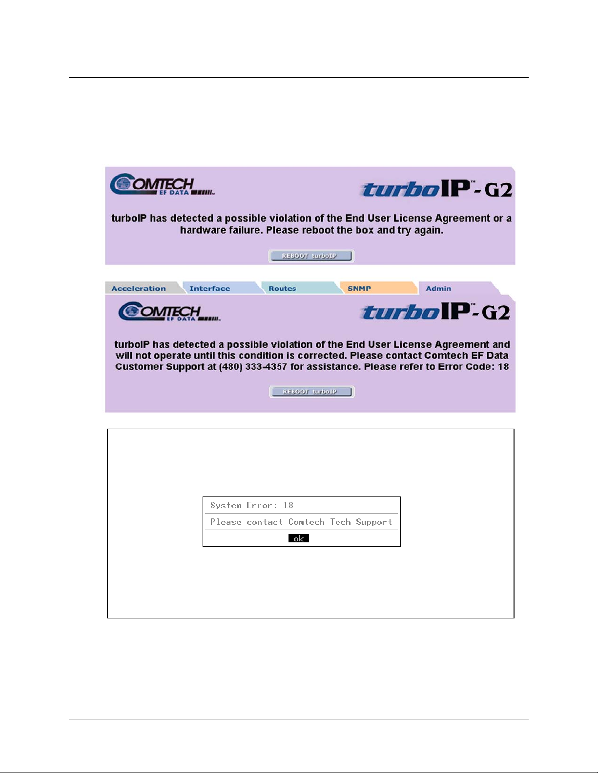
End User License Agreement (EULA) Copy Protection
turboIP-G2 uses copy protection mechanisms to enforce the End User License Agreement (EULA).
If the unit detects tampering, it will stop functioning and display an appropriate message.
Sample messages include:
xvi
Page 19

turboIP-G2 Performance Enhancement Proxy Revision 2
Preface CD-TURBOIP-G2
Warrant y Policy
Comtech EF Data’s turboIP-G2 is warranted against defects in material and
workmanship for a period of one year from the date of shipment. During the warranty
period, Comtech EF Data will, at its option, repair or replace products that prove to be
defective. Repairs are warranted for the remainder of the original one year warranty or a
90 day extended warranty, whichever is longer.
For equipment under warranty, the owner is responsible for freight to Comtech EF Data
and all related customs, taxes, tariffs, insurance, etc. Comtech EF Data is responsible for
the freight charges only for return of the equipment from the factory to the owner.
Comtech EF Data will return the equipment by the same method (i.e., Air, Express,
Surface) as the equipment was sent to Comtech EF Data.
All equipment returned for warranty repair must have a valid RMA number issued prior
to return and be marked clearly on the return packaging. Comtech EF Data strongly
recommends all equipment be returned in its original packaging.
Comtech EF Data Corporation’s obligations under this warranty are limited to repair or
replacement of failed parts, and the return shipment to the buyer of the repaired or
replaced parts.
Limitations of Warranty
The warranty does not apply to any part of a product that has been installed, altered,
repaired, or misused in any way that, in the opinion of Comtech EF Data Corporation,
would affect the reliability or detracts from the performance of any part of the product, or
is damaged as the result of use in a way or with equipment that had not been previously
approved by Comtech EF Data Corporation.
The warranty does not apply to any product or parts thereof where the serial number or the
serial number of any of its parts has been altered, defaced, or removed.
The warranty does not cover damage or loss incurred in transportation of the product.
The warranty does not cover replacement or repair necessitated by loss or damage from
any cause beyond the control of Comtech EF Data Corporation, such as lightning or other
natural and weather related events or wartime environments.
The warranty does not cover any labor involved in the removal and or reinstallation of
warranted equipment or parts on site, or any labor required to diagnose the necessity for
repair or replacement.
The warranty excludes any responsibility by Comtech EF Data Corporation for incidental or
consequential damages arising from the use of the equipment or products, or for any inability
to use them either separate from or in combination with any other equipment or products.
xvii
Page 20

turboIP-G2 Performance Enhancement Proxy Revision 2
Preface CD-TURBOIP-G2
A fixed charge established for each product will be imposed for all equipment returned
for warranty repair where Comtech EF Data Corporation cannot identify the cause of the
reported failure.
Exclusive Remedies
Comtech EF Data Corporation’s warranty, as stated is in lieu of all other warranties,
expressed, implied, or statutory, including those of merchantability and fitness for a
particular purpose. The buyer shall pass on to any purchaser, lessee, or other user of
Comtech EF Data Corporation’s products, the aforementioned warranty, and shall
indemnify and hold harmless Comtech EF Data Corporation from any claims or liability
of such purchaser, lessee, or user based upon allegations that the buyer, its agents, or
employees have made additional warranties or representations as to product preference or
use.
The remedies provided herein are the buyer’s sole and exclusive remedies. Comtech EF
Data shall not be liable for any direct, indirect, special, incidental, or consequential
damages, whether based on contract, tort, or any other legal theory.
xviii
Page 21

turboIP-G2 Performance Enhancement Proxy Revision 2
Preface CD-TURBOIP-G2
Customer Support
Review the Warranty Policy before contacting Comtech EF Data Technical Support or
Customer Service.
Contact Comtech EF Data for:
• Technical Support – Product support or training.
• Customer Service – Information on returning an in-warranty or out-of-warranty product for
upgrade or repair. Be prepared to provide the product model number and its serial number.
Contacting Comtech EF Data
Contact Comtech EF Data Customer & Technical Support during normal business hours (Monday
through Friday, 8 A.M. to 5 P.M Mountain Standard Time (MST)):
For: Contact:
Telephone +1.480.333.2433
turboIP® Performance
Enhancement Proxies
(PEP) Technical Support
Email cdmipsupport@comtechefdata.com
Fax +1.480.333.2161
Comtech EF Data Main Number +1.480.333.2200
Web Site http://www.comtechefdata.com
Mailing Address
2114 West 7th Street
Tempe, Arizona 85281 USA
xix
Page 22

turboIP-G2 Performance Enhancement Proxy Revision 2
Preface CD-TURBOIP-G2
Returning a Product for Upgrade or Repair
Step Task
1
2
3
Go to the Comtech EF Data Service page (http://www.comtechefdata.com/service.asp)
and read the Return Material Authorization section in its entirety.
Request a Return Material Authorization Number:
• On the Comtech EF Data Service page: Select the Return Material
Authorization hyperlink.
• On the Comtech EF Data Support page
(http://www.comtechefdata.com/support.asp): Click [Send RMA Request]
(http://www.comtechefdata.com/rmaform.asp);
• Fill out the RMA form completely;
• Click [Send Email].
• Alternately:
o Send an e-mail providing this same detailed information to Comtech EF Data
Customer Service (service@comtechefdata.com).
o Contact Comtech EF Data Customer & Technical Support by phone or fax.
Pack the product in its original shipping carton and protective packaging.
4
Ship the product back to Comtech EF Data. Shipping charges should be prepaid.
xx
Page 23
1.1 Overview
The turboIP-G2 is Comtech EF Data’s next generation turboIP Performance Enhancement
Proxies (PEPs) product, built specifically to meet the satellite acceleration needs of current
Department of Defense (DOD) Satcom programs. The turboIP-G2’s smart congestion controls
allow it to accelerate in the DOD’s most complex networks, and is compatible with the U.S.
military’s most commonly deployed Time Division Multiple Access (TDMA) technologies.
The turboIP-G2 combines standards-compliance, interoperability, DOD security and management
features, and Wide Area Network (WAN) optimization into a single commercial off-the-shelf
(COTS) platform. It serves as a true plug-and-play device that can be dropped into any network –
regardless of the architecture – with virtually no user configuration required. Accelerating at
speeds of 15, 45, or 155 Mbps, the turboIP-G2 works equally as well as a hub device or a remote
site PEP.
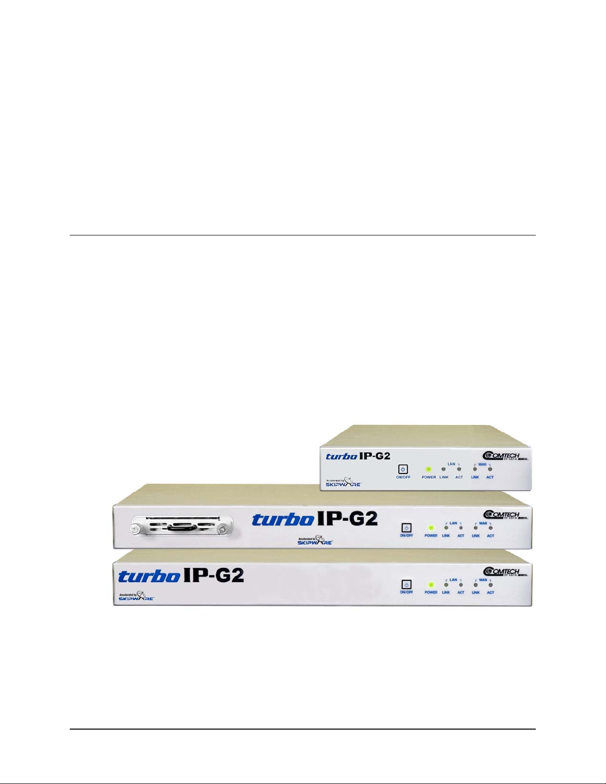
Chapter 1. INTRODUCTION
Figure 1-1. turboIP-G2 1/2-Width (top) and Full-Width 1RU Units (Chassis Only)
Figure 1-1 shows the turboIP-G2 chassis, which is available in three versions – as a 1/2-Width
unit (shown
the purpose of brevity, all versions are collectively referred to throughout this manual as the
turboIP-G2.
at top), or as a Full-Width 1RU unit with either removable or fixed hard drive. For
1–1
Page 24

turboIP-G2 Performance Enhancement Proxy Revision 2
Introduction CD-TURBOIP-G2
The turboIP-G2 is fully compliant with the Space Communications Protocol Standard Transport
Protocol (SCPS-TP) standard and provides optimized interoperability with all models of turboIP,
past and present.
1.1.1 Key Operational Features
• Developed in the USA
• 1 year Hardware warranty (see PREFACE for details)
• Additional Software Warranties and Complete System Warranties Available
• Available in 1RU Full-Width (19” rack) form factor, with fixed or removable hard drive
• Also available in hardened 1RU 1/2-Width (19” rack) form factor
• Optional rack kit allows left, right or dual mount rack installation of 1/2-Width unit(s)
• Meets DOD Security Requirements
• SCPS-TP (MIL-STD-2045-44000)
• Available in 15 Mbps, 45 Mbps, or 155 Mbps WAN rates
• WAN Optimization (available on units manufactured from November 2010 forward)
• Implements Open Standards
• IPv4/IPv6 Acceleration and Management
• Selective Acceleration (U.S. Patent 6,937,560)
• Intelligent Congestion Control
• Support for up to 10,000 Sessions
• Data and Header Compression
• VLAN (802.1Q) and GRE Tunnel (RFC 2784) Support
• Automatic Window Scaling (RFC 1323)
• Explicit Congestion Notification (ECN) (RFC 3168)
• Rate Pacing versus Dynamic Bandwidth Support
• Black Hole Detection & Recovery
• Path Maximum Transmission Unit (MTU) Discovery
• Tolerates Packet Reordering & Large Queues
• Asymmetrical Route Management
• Dual OR Single Interface Mode with Policy-Based Routing
• Common Internet File Support (CIFS) i.e., Microsoft File Sharing Acceleration
• Data Redundancy Elimination (DRE) Caching
• WebCache – HTTP Caching Engine
• Persistent LZ Compression
1–2
Page 25

turboIP-G2 Performance Enhancement Proxy Revision 2
Introduction CD-TURBOIP-G2
• Simplified User Configuration and Management
• Quick Start
• Flexible Management Interfaces
• Enhanced Performance Analysis Tools
• SNACK/SACK
• Size, Weight, and Power considerations (SWaP)
• 10/100/1000 Mbps Auto Sensing, Auto Crossover Capabilities
• Dedicated Traffic (WAN, LAN) ports and Management Ethernet Port (available on units
manufactured from November 2010 forward)
• Fail-to-Wire
1.2 Features
1.2.1 Physical Description
The turboIP-G2 Full-Width unit (with fixed or removable hard drive) is constructed as a 1RUhigh, rack-adaptable chassis. For rack-mounted configurations, handles are assembled to the front
sides of the chassis that allow easy removal from and placement into a rack.
Similarly, rack adapter kits are available for the 1/2-Width models that allow installation in either
single or dual configuration into a standard 19” wide rack. Handles provided with the adapter kits
are assembled to the front sides of the chassis to allow easy removal from an d placement into a
rack.
Both the Full-Width and 1/2-Width units may be freestanding if desired.
1.2.1.1 Major Assemblies (Standard and Optional)
CEFD Part No. Description
KT-0000172 turboIP-G2 1/2-Width Rack-mount Chassis
KT-0000171 turboIP-G2 Full-Width Rack-mount Chassis w/Fixed Hard Drive
KT-0000271 turboIP-G2 1/2-Width Rack-mount Chassis w/Removable Hard Drive
PP-0000049 Optional Rack Mount Kit (1/2-Width Single or Dual Unit Mount)
1–3
Page 26
turboIP-G2 Performance Enhancement Proxy Revision 2
Introduction CD-TURBOIP-G2
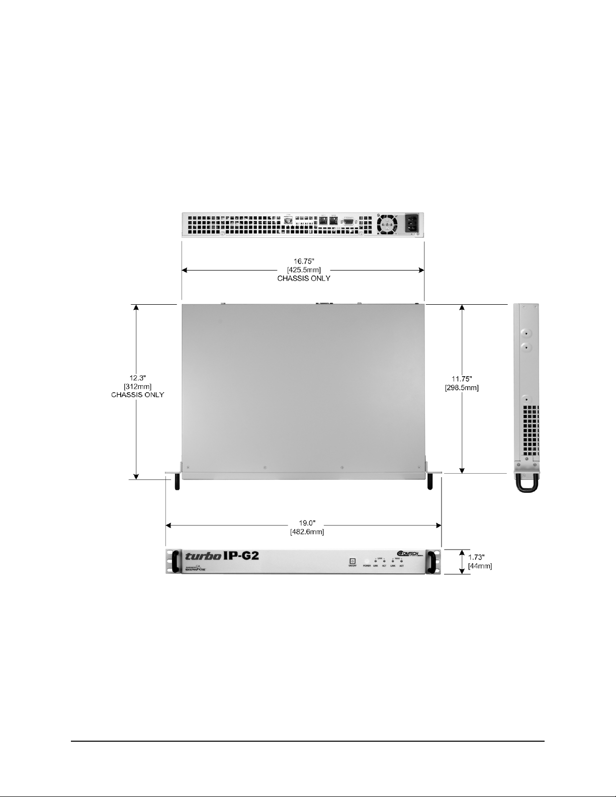
1.2.2 Dimensional Envelopes
This section provides the dimensional envelopes for the turboIP-G2 Full-Width and 1/2-Width
and configurations (both single and dual rack setups using the optional Rack Mount Kit
PP-0000049).
Note: All dimensions provided in this section are considered approximate, and are furnished for
reference only.
Figure 1-2. turboIP-G2 Dimensional Envelope – Full-Width Chassis (Typical)
1–4
Page 27
turboIP-G2 Performance Enhancement Proxy Revision 2
Introduction CD-TURBOIP-G2
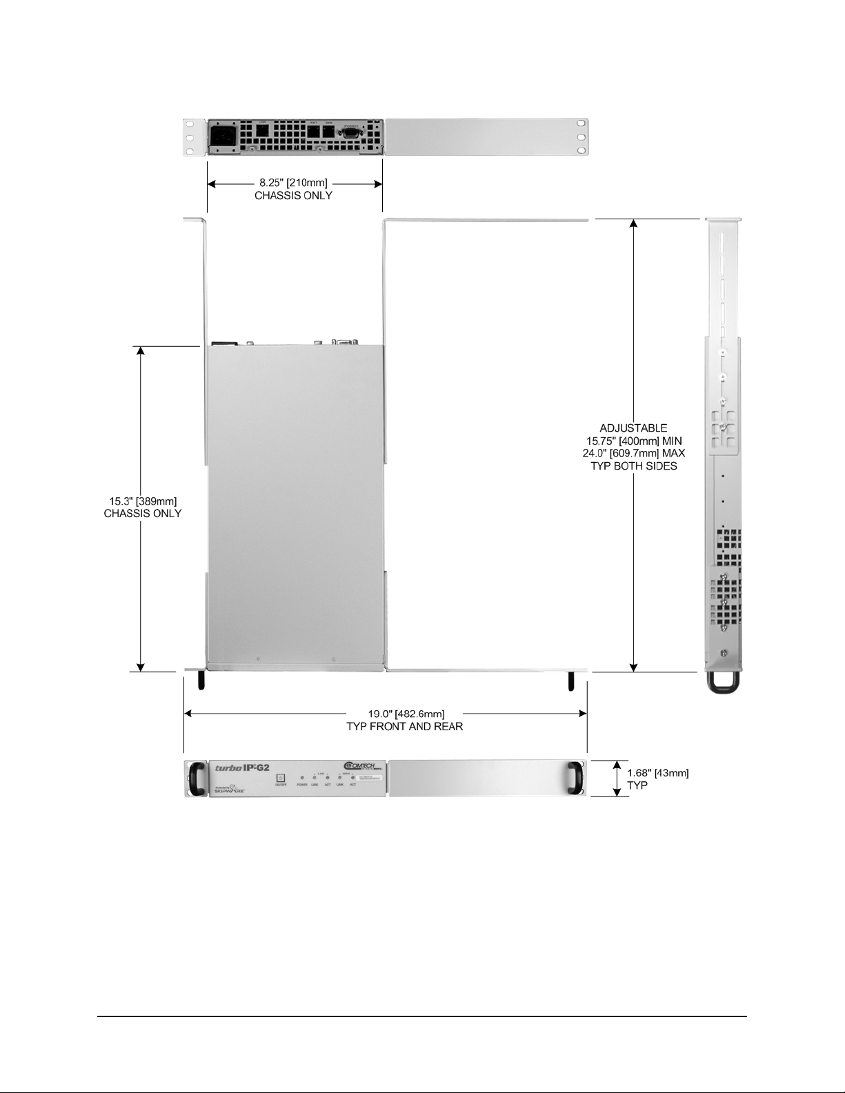
Figure 1-3. turboIP-G2 Dimensional Envelope – 1/2-Width Chassis (Single Unit Mount)
1–5
Page 28
turboIP-G2 Performance Enhancement Proxy Revision 2
Introduction CD-TURBOIP-G2
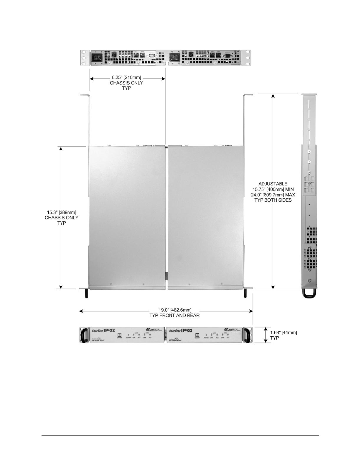
Figure 1-4. turboIP-G2 Dimensional Envelope – 1/2-Width Chassis (Dual Unit Mount)
1–6
Page 29
turboIP-G2 Performance Enhancement Proxy Revision 2
Introduction CD-TURBOIP-G2
1.2.3 Physical Features
1.2.3.1 Front Panels
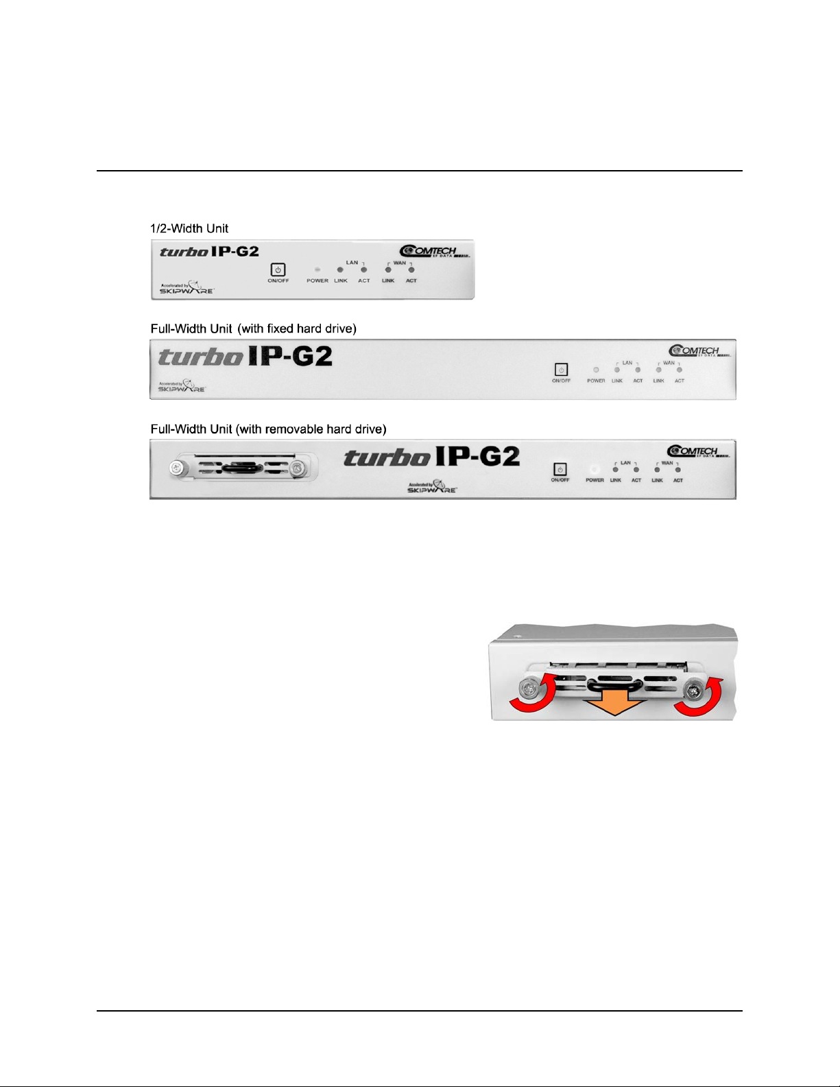
Figure 1-5. turboIP-G2 Front Panels (Chassis Only)
Figure 1-5 shows the turboIP-G2 1/2-
Width and Full-Width unit front panels. All units feature a
power switch with a sealed membrane overlay. Five Light-emitting Diode (LED) lights indicate
power on, and indication of link and activity for LAN and WAN.
Full-Width unit with removable hard drive: The
turboIP-G2 meets strong security requirements for
cached data by providing an optional secure erase
hard drive technology, allowing for deeper storage
and history buffers, while maintaining guaranteed
security of stored data.
1–7
Page 30
turboIP-G2 Performance Enhancement Proxy Revision 2
Introduction CD-TURBOIP-G2
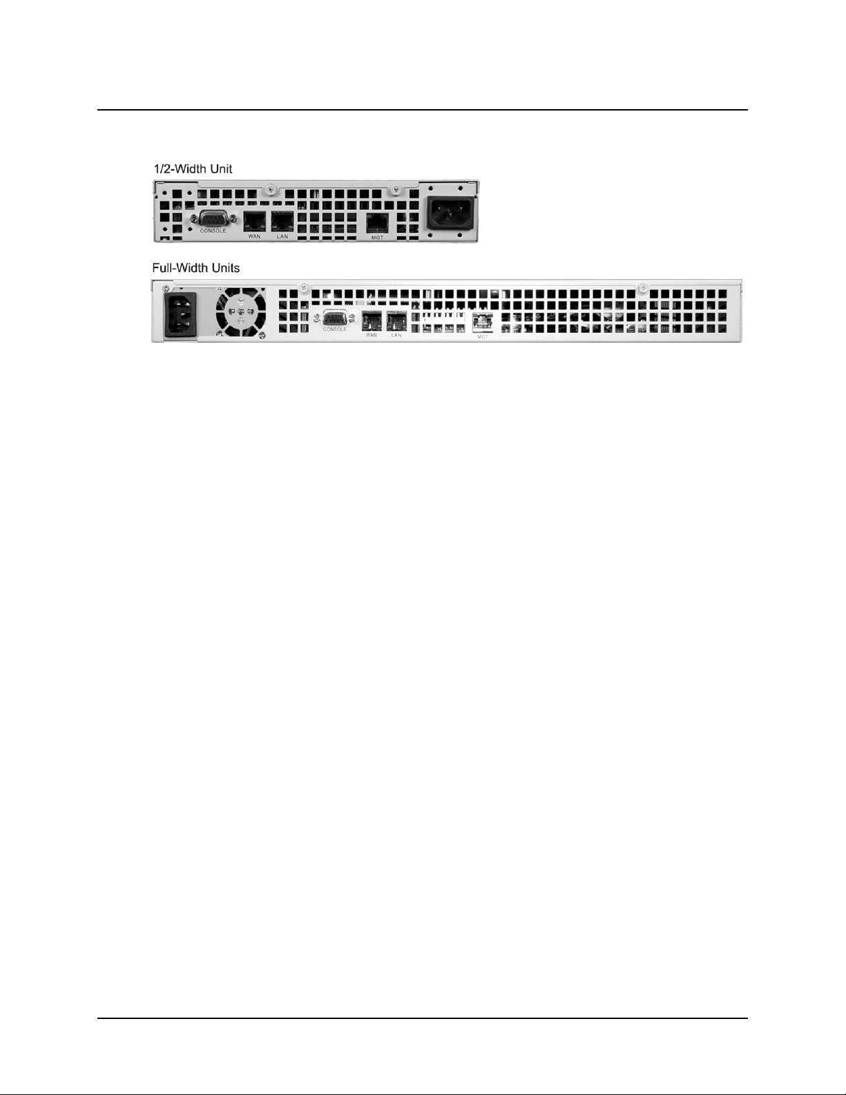
1.2.3.2 Rear Panels
Figure 1-6. turboIP-G2 Rear Panels (Chassis only)
Figure 1-6 s
configurations. Each chassis features an EIA-232 female port, two RJ-45 10/100/1000 BaseT
ports, an RJ-45 Management Port (with units manufactured from November 2010 forward), and
an IEC-320 AC Power Receptacle. See Chapter 3. REAR PANEL CONNECTORS for
detailed information about these connectors and their functionality.
hows the rear panel for both the 1/2-Width and Full-width turboIP-G2 chassis
1–8
Page 31

turboIP-G2 Performance Enhancement Proxy Revision 2
Introduction CD-TURBOIP-G2
1.2.4 Acceleration and WAN Optimization
WAN Optimization is available with units manufactured from November 2010
forward.
All turboIP Performance Enhancement Proxies combat the inherent challenges of transmitting
Transmission Control Protocol (TCP) over satellite links. The units provide transparent
acceleration of TCP sessions, increasing throughput over satellite links while requiring minimal
topology changes. They provide reliable connection-oriented, end-to-end data transfer for user
applications.
Powered by the industry-leading SCPS implementation, SkipWare, the turboIP-G2 overcomes
performance loss associated with conditions common in tactical networking, including weather
effects, blockage, latency and interference.
The turboIP-G2 complies with DOD requirements for volatile memory data storage by providing
RAM-based web caching. The turboIP-G2 also provides support for both IPv4 and IPv6,
allowing DOD programs to satisfy IPv6 conformance mandates.
1.2.4.1 TCP/IP Performance Limitations
Due to its design, TCP/IP does not perform well over impaired links. The link impairment could
be due to delay or noise or both. A typical satellite link suffers due to high delay and high noise.
The main reasons for poor TCP/IP performance over an impaired link can be summarized as:
• Slow start algorithm. Slow start algorithm allows a TCP sender to increase the data
transmission rate without overwhelming the network. It achieves this goal by gradually
increasing the number of unacknowledged segments at the start of the session. The time
required for an acknowledgement over the satellite link severely limits the ramp up in
transmission rate.
• TCP window size. The most unacknowledged data that a TCP sender can have
outstanding is limited by the sender’s window size. This limits the transmission rate in
the steady state to Window_Size/Round_Trip_Time (e.g., for a typical receive windows
size of 64 Kbytes and satellite round trip time of 540 ms, the maximum throughput is
limited to approximately 121 kbps).
• Congestion avoidance algorithms. The congestion avoidance and control mechanism of
TCP attributes packet loss to network congestion, as opposed to corruption due to noise
in the channel. This leads to drastic reduction in transmission rates. Recovery from
congestion is slowed due to the high round trip time and noise in the satellite channel.
1–9
Page 32

turboIP-G2 Performance Enhancement Proxy Revision 2
Introduction CD-TURBOIP-G2
1.2.4.2 TCP/IP Performance Enhancement Proxy
Comtech EF Data’s turboIP-G2 Performance Enhancement Proxy is designed to alleviate TCP/IP
bottlenecks in an impaired environment (high delay, high bit error rate, or both), while preserving
interoperability with any TCP device. It achieves this by combining TCP with a number of
enhancements that modernize IP transport.
turboIP-G2 is based on SCPS-TP, the Transport Protocol of SCPS, an open standard specifically
defined for space communications. This standard is open, published, and internationally
distributed. SCPS-TP is an ISO standard (15893), a CCSDS standard (714.0-B-1), and a
MIL-STD (MIL-STD-2045-44000).
turboIP-G2 is fully compatible with network devices that use TCP, supporting existing Internet
standards, including network congestion and retransmission schemes. This allows turboIP-G2 at
one end of the link to operate with TCP devices at the other end of the link without the need for a
peer turboIP-G2 device, providing partial performance enhancement. However, it is
recommended that TCP traffic pass through a pair of turboIP
Proxies, in order to take full advantage of the SCPS-TP protocol.
The key features of turboIP-G2 that help alleviate TCP/IP performance bottlenecks are:
• Quick Start. turboIP-G2 makes full and immediate use of the links available, eliminating
the inefficiencies of the TCP slow-start algorithm.
• Window Scaling. turboIP-G2 supports window sizes up to 1 GB, far exceeding the
standard TCP window size of 64 Kbytes.
• Intelligent Congestion Control. turboIP-G2 is optimized for real-world, mixed-loss
environments. It is capable of distinguishing data corruption from congestion-induced
data loss. Doing so prevents unnecessary activation of congestion control mechanisms,
which can lead to significant reductions in transmission rates.
• Selective Negative Acknowledgments (SNACKs). SNACKs identify specific lost or
damaged packets and request retransmission of those packets. This provides for quicker
recovery and better bandwidth utilization in lossy environments.
• Path MTU Discovery. turboIP-G2 allows Slipware to dynamically detect the allowed
MTU for the path between the Skip ware gateway and the peer gateway or end systems
for accelerated traffic, thus eliminating fragmentation of TCP segments that are too large
for the path MTU.
• Tolerance for packet reordering. turboIP-G2 prevents spurious retransmissions due to
packet reordering in the path between two skip ware gateways
• Support for large queues with congestion control. turboIP-G2 prevents spurious
retransmissions timeouts (RTO) caused by an increase in RTT due to queuing, improving
throughput when using the Per-Connection congestion control on long delay networks
that support large queues.
TM
Performance Enhancement
1–10
Page 33

turboIP-G2 Performance Enhancement Proxy Revision 2
Introduction CD-TURBOIP-G2
• Explicit Congestion Notification (ECN). Traditionally, TCP/IP networks signal
congestion by dropping packets. When ECN is successfully negotiated, an ECN-aware
router may set a mark in the IP header instead of dropping a packet in order to signal
impending congestion. The receiver of the packet echoes the congestion indication to the
sender, which must react as though a packet was dropped.
• Rate Pacing. turboIP-G2 meters out bursty traffic at a rate not to exceed the configured
transmission rate of the satellite channel. This prevents the satellite channel from
becoming congested.
• Per-Connection. turboIP-G2 allows Per-Connection Mode to support dynamic
bandwidth paths, where the bandwidth may be different for any of the paths being
accelerated by the turboIP-G2. Treats any loss as an indication of congestion and reduces
the throughput by half
• Error Tolerance. turboIP-G2 allows Error Tolerance Mode to support dynamic
bandwidth paths, where the bandwidth may be different for any of the paths being
accelerated by the turboIP-G2. Will tolerate 1/12 amount of loss in a window before
reducing the throughput to half.
When Rate Pacing Mode, Pre-Connection Mode or Error Tolerance Mode are
selected to optimize TCP acceleration performance:
• Rate Pacing Mode should be used when the bandwidth path for accelerated
TCP traffic remains constant with the set WAN Transmission Rate.
• Per-Connection Mode should be used to support dynamic bandwidth paths,
where the bandwidth may be different for any of the paths being accelerated by
the turboIP-G2 and there is low congestion in networks.
• Error Tolerance Mode should be used to support dynamic bandwidth paths,
where the bandwidth may be different for any of the paths being accelerated by
the turboIP-G2 and there is high congestion in networks.
1.2.4.3 Selective Acceleration
Selective Acceleration implemented by the Comtech turboIP-G2 is a mechanism for providing
different Quality of Service (QoS) for different datagrams. Selective Acceleration only applies to
IPv4 datagrams that are received on the LAN interface and forwarded to the WAN interface.
Selective Acceleration is implemented as an ordered table of rules that determine the QoS to be
provided for traffic passing through the turboIP-G2. The rules have three parts:
1) An accounting part that specifies the location and status of the rule in the table;
2) A filter part that matches the datagram’s passing through the turboIP-G2 to each rule;
3) A QoS part that determines how the data that matches the rule is to be treated. Each rule can
specify that either all packets matching the rule be dropped or the following QoS parameters
be applied:
1–11
Page 34

turboIP-G2 Performance Enhancement Proxy Revision 2
Introduction CD-TURBOIP-G2
• A priority level;
• A maximum data rate (bandwidth) for all traffic matching the rule;
• Whether or not to accelerate TCP sessions matching the rule (i.e., invoke SCPS-TP).
1.2.4.4 Data and Header Compression
The turboIP-G2 supports header and payload compression of accelerated TCP traffic.
Compression is enabled or disabled by a global setting. If it is enabled, both header and data
compression will be attempted on all new accelerated sessions. Compression will be negotiated
during the TCP connection establishment. Therefore, even if the turboIP-G2 has compression
enabled, and if the peer turboIP-G2 does not also have compression enabled, then the session will
not be compressed.
Data compression on accelerated TCP flows will be handled on a segment-by-segment basis. The
compressibility of each segment payload will be evaluated individually and only those segments
where the impacts would be beneficial will be compressed. If a session is to be compressed, then
the segments corresponding to that session will be compressed only if:
• The uncompressed payload length is greater than 90 octets, and
• The compressed length is not larger than two octets smaller than the uncompressed
length.
1.2.4.5 Minimum Compression Ratio
The compression ratio is defined as the ratio of the sum of the sizes of all TCP segments in an
uncompressed session to the sum of the sizes of the TCP segments if that same session were
compressed. Note that this is different from the definition used in the compression ratio statistic.
A minimum compression ratio of 1.91:1 shall be achieved with the Canterbury corpus and 1.63:1
with the Calgary corpus, when the data is transferred through the turboIP-G2 using FTP.
The turboIP-G2 shall never produce a compression ratio less than 1 with any data, that is, the size
of the compressed flows shall always be less than or equal to the size that the flow would have
been if compression were disabled for that flow.
1.3 Software Update
The turboIP-G2 is factory-shipped with the latest version of operating software. If a software
update is needed, it can be downloaded from Comtech EF Data’s Web site
(www.comtechefdata.com
business hours via e-mail or on CD by standard mail delivery.
The turboIP-G2 Software Update process is as follows:
) or obtained from Comtech EF Data Customer Support during normal
1–12
Page 35

turboIP-G2 Performance Enhancement Proxy Revision 2
Introduction CD-TURBOIP-G2
• Perform the update without opening the turboIP-G2 by connecting the MGT port on the
turboIP-G2 rear panel to the Ethernet port of a user-supplied PC.
• Download the software update via the Internet (or as otherwise obtained from Comtech
EF Data Customer Support) to the user PC.
• Transfer the software update via automated File Transfer Protocol (FTP) from the user
PC to the turboIP-G2. See Chapter 4. CONFIGURATION
AND UPDATING.
1.4 F A ST Sy stem
The turboIP-G2 incorporates a number of optional features. In order to permit a lower initial cost,
the unit may be purchased with only the desired features enabled.
If, at a later date, the user wishes to upgrade the functionality of a unit, Comtech EF Data
provides Fully Accessible System Topology (FAST), a technology which permits the purchase
and installation of options through special authorization codes. These unique Fast Access Codes
may be purchased from Comtech EF Data during normal business hours, and then loaded into the
unit via the rear panel ‘CONSOLE’ port or, on units manufactured after November 2010, the rear
panel ‘MGT’ port.
1.4.1 FAST System Theory
FAST allows an operator to order a unit precisely tailored for the initial application. When
service requirements change, FAST allows the operator to upgrade the topology of the unit onlocation, within minutes, and without having to remove the unit from the setup. This accelerated
upgrade is possible due to FAST’s extensive use of the programmable logic devices incorporated
into Comtech EF Data products.
1.4.2 FAST Implementation
Comtech EF Data’s FAST system is factory-implemented in the turboIP-G2. All FAST options
are available through the basic platform unit at the time of order. FAST allows immediate
activation of available options – first, upon entry of the FAST Access Code, and then by setting
the desired operational parameters via the remote control or Web Server Graphical User
interfaces.
1.4.3 FAST Accessible Options
• IPv6 acceleration and management – Pending
• Data and Header Compression
• HTTP RAM-based Caching – Pending
• CIFS/WAFS Acceleration – Pending
• 45 Mbps WAN rate
• 155 Mbps WAN rate
1–13
Page 36

turboIP-G2 Performance Enhancement Proxy Revision 2
Introduction CD-TURBOIP-G2
1.5 Remote Control
The operator may monitor and control (M&C) the turboIP-G2 through the ‘CONSOLE’ M&C
serial port (RS-232 or RS-485 2- or 4-wire), or via 10/100/1000 BaseT Ethernet using the RJ-45
‘MGT’ port (available on units manufactured from November 2010 forward).
1.6 Summary of Specifications
Feature Specifications
• LAN, WAN, MGT (1 each): RJ-45 10/100/1000BaseT Ethernet, auto-sensing and
Rear Connectors (5)
(as of November 2010)
auto-crossover
• CONSOLE: EIA-232 DB-9F
• AC POWER: IEC-320
Front Panel Status
LEDs
Temperature
Humidity Operating: 5 to 90% @ 40° C (104° F), non-condensing
Vibration
Shock Operating: 15G acceleration peak (1 ms duration)
Safety EN-60950 (CE)
EMC FCC Part 15 Subpart B / EN55022-EN55024 (CE)
Chassis Half-Width
Chassis Full-Width
• Link and activity for LAN, WAN
• Power indication with on/off control
Operating:
Storage:
Operating: 5 to 17 Hz, 0.1'' double amplitude displacement 17 to 500 Hz, 1.5G
acceleration peak-to-peak (max.)
Dimensions:
Weight:
Power:
Dimensions:
Weight:
Power:
5° to 60° C (140° F)
0° to 75° C (167° F)
1.68H x 8.25W x 15.3D inches (43H x 210W x 389D mm)
<7 lbs (3.2 kg)
100 to 240V AC, 50 to 60 Hz, 90W max.
1.73H x 16.75W x 12.3D inches (44H x 425.4W x 312D mm)
8.5 lbs (3.86 kg)
90 to 264V AC, 47 to 63 Hz, 110W max.
Cooling Fans Two internal fans
1–14
Page 37

Chapter 2. INSTALLATION AND
2.1 Unpacking and Inspection
The turboIP-G2 and its Installation and Operation Manual were packaged and shipped in a
reusable cardboard carton containing protective foam spacing.
This equipment contains parts and assemblies sensitive to damage by
Electrostatic Discharge (ESD). Use ESD precautionary procedures when
handling the equipment.
Once opened, inspect the shipment:
Step Task
STARTUP
1
2
3
4
5
Keep all shipping materials for storage or reshipment.
Check the packing list to ensure the shipment is complete.
Inspect the equipment for any possible damage incurred during shipment. Contact
the carrier and Comtech EF Data immediately to submit a damage report if damage
is evident.
Review the Installation and Operation Manual carefully to become
familiar with operation.
Proceed to Section 2.2 Rack Mounting the turboIP-G2.
2–1
Page 38

turboIP-G2 Performance Enhancement Proxy Revision 2
Installation and Startup CD-TURBOIP-G2
2.2 Rack Mounting the turboIP-G2
Figure 2-1 shows a rack “cut-away” side view with two typical turboIP-G2 rack-mounted
configurations:
• Installation of the Full-Width turboIP-G2 using the installed Universal Front Rack
Brackets.
• Installation of the 1/2-Width (half-rack) turboIP-G2 – either as a single 1/2-Width
turboIP-G2 or as a pair – using the optional PP-0000049 Rack Mount Kit.
Mount equipment in the rack(s) as required for efficient arrangement and operation. If the
turboIP-G2 is to be mounted in a rack, ensure that there is adequate clearance for ventilation. In
rack systems where there is high heat dissipation, forced air cooling must be provided by top- or
bottom-mounted fans or blowers. Under no circumstance should the highest internal rack
temperature be allowed to exceed 60°C (140°F).
Figure 2-1. Typical turboIP-G2 Full-Width and 1/2-Width Unit Rack Installations
2–2
Page 39

turboIP-G2 Performance Enhancement Proxy Revision 2
Installation and Startup CD-TURBOIP-G2
2.2.1 Rack Mounting – Full-Width turboIP- G 2 Configuration
The tool required for this installation is a medium Phillips™ screwdriver. Each Full-Width
turboIP-G2 is provided with two Universal Front Rack Brackets (with pre-assembled handles
attached).
(2X) Universal Front Rack Bracket (3X) #6-32 x 1/4” lg. screws per side
(with pre-assembled handle)
Final assembly of a Full-Width turboIP-G2 is accomplished as follows:
Figure 2-2. Full-Width Configuration – Universal Front Rack Bracket Installation
Step Single Unit Mounting Procedure
1
2
As shown in Figure 2-2: Secu
assembled handle) to each side of the turboIP-G2 Full-Width chassis using three
(3) of the provided M3 x 6mm long flat head machine screws per side.
As shown in Figure 2-1: Ins
a 1RU rack space; use the front mounting ears to secure the configuration to the
rack’s front mounting rails as needed (mounting hardware provided by customer).
re one (1) Universal Front Rack Bracket (with pre-
tall the turboIP-G2 Full-Width chassis assembly into
2–3
Page 40

turboIP-G2 Performance Enhancement Proxy Revision 2
Installation and Startup CD-TURBOIP-G2
2.2.2 1/2-Width turboIP-G2 – Rack Mounting Configurations using Kit PP-0000049
Using the Rack Mount Kit (CEFD Part Number PP-0000049), a single 1/2-Width turboIP-G2 or a
1/2-Width turboIP-G2 pair may be installed into a 1RU rack space. Figure 2-3 shows th
individual components provided in this kit; the item numbers in this illustration are referenced in
the assembly instructions provided on the pages that follow.
e
Quantity Required from Kit
Figure 2-3
Item No.
1 ─ 1 Bracket, Rear – Chassis Link
2 1 2 Bracket, Short – Universal (RH/LH) Front Mounting Ear
3 1 2 Bracket, Short – Universal (RH/LH) Rear Mounting Ear
4 1 ─ Bracket, Long – Universal (RH/LH) Front Mounting Ear
5 1 ─ Bracket, Long – Universal (RH/LH) Rear Mounting Ear
6 ─ 2 Bridge Clip Lock Link (Block & Pin Assembly – Front Docking)
7 2 2 Handle – M4 thread
8 4 4 Machine Screw –Flat Head, Phillips, M4 x 8mm lg (for Item 7)
9 A/R (20 provided) A/R (20 provided)
10 ─ 8 Machine Screw – Flat Head, Phillips, #6-32 x 1/4" lg (for Item 1)
11 ─ 4 Machine Screw – Flat Head, Phillips, #6-32 x 3/8” lg (for Item 6)
Single1/2-Width
Unit Mounting
Dual 1/2-Width
Units Mounting
Machine Screw – Hex Head w/washer, Phillips, #6-32 x 1/4" lg (for
Items 2 thru 5)
Description
Figure 2-3. PP-0000049 Rack Mount Kit
(For 1/2-Width Single and Dual Mounting Configurations)
2–4
Page 41

turboIP-G2 Performance Enhancement Proxy Revision 2
Installation and Startup CD-TURBOIP-G2
2.2.2.1 1/2-Width turboIP-G2 – Single Unit Rack Mount Configuration
The tools required for this installation are a medium Phillips™ screwdriver and, optionally for use
with Item 9, a 1/4” drive socket. This configuration, as illustrated in Figure 2-4, is
follows (refer back to Figure 2-3 to iden
Step 1/2-Width Single Unit Mount Assembly Procedure
tify all parts referred to in these instructions by Item #):
assembled as
1
2
3
As shown in Figure 2-4:
Brackets (Items 2 and 3) to the left side of the 1/2-Width chassis, and the Front and
Rear Long Brackets (Items 4 and 5) to the right side of the chassis, using the #6-32 x
1/4" long hex head machine screws (Item 9).
Do not fully tighten the rear bracket screws until the assembly is adjusted for proper
rack mounting (as per Step 3 of this procedure).
As shown in Figure 2-4: Install the handle
bracket rack ears using the M4 x 8mm long flat head screws (Item 8).
As shown in Figure 2-1: Install the turboIP-G2 assembly into the rack as neede d. The
rear brackets are slotted to adjust the assembly to suit the requi red rack depth.
Depending on the style of rack used:
a. Bolt the assembly into the rack using the front mounting ears (mounting
hardware provided by customer).
b. Slide the rear brackets back or forth until the rear bracket mounting ears
contact the rear rack mounting rail.
c. Mark the left and right rear brackets at the inside edge of the unit chassis , and
then remove the assembly from the rack.
d. Tighten down the rear bracke t screws on both sides, making sur e the marked
depth is maintained for the rear brackets.
Reinstall the assembly into the rack. Use the front and rear mounting ears on the rack
brackets to secure the configuration to the rack mounting rails as needed (mounting
hardware provided by customer).
Assemble one each of the Front and Rear Universal Short
s (Item 7) onto the right and left front
Figure 2-4. 1/2-Width Rack Mount Kit Assembly – Single Unit Configuration
2–5
Page 42

turboIP-G2 Performance Enhancement Proxy Revision 2
Installation and Startup CD-TURBOIP-G2
2.2.2.2 1/2-Width turboIP-G2 – D ual Rack Mount Configuration
The tools required for this installation are a medium Phillips™ screwdriver and, optionally for use
with Item 9, a 1/4” drive socket. This configu ration, as illustrated in Figure 2-5,
follows (refer back to Figure 2-3 to identify all parts referred to in these instructions by
Step 1/2-Width Dual Unit Mount Assembly Procedure
is assembled as
Item #):
1
2
3
4
5
As shown in Figure 2-6: Assemble a Bridge Clip (Item 6) to each turboIP-G2 1/2-
Width unit using the #6-32 x 3/8” long flat head machine screws (Item 11) as
follows:
a. Assemble the clip for the left-hand turboIP-G2 unit to the right side of the
chassis so that the pin is po sitioned t op facing t owards re ar.
b. Assemble the clip for the right-hand turboIP-G2 unit to the left side of the
chassis so that the pin is po sitioned bottom faci ng toward s front.
As shown in Figure 2-6: Dock the turboI P-G2 pair by pla cing the left-ha nd unit forward
of the right-hand unit, and then guid ing the pai r toget her until th e guide pins for e ach cli p
are fully engaged and the clip surfaces abut. Figure 2-5
As shown in Figure 2-7: Secure the Chassis Link Rear Bracket (Item 1) to the rear
panels of both 1/2-Width chassis, using the #6-32 x 1/4" long flat head machine screws
(Item 10).
As shown in Figure 2-5: Assemble the
(Items 2 and 3) to the sides of the chassis using the #6-32 x 1/4" long hex head
machine screws (I
Do not fully tighten the rear bracket screws until the assembly is adjusted for proper
rack mounting (as per Step 6 of this procedure).
As shown in Figure 2-5:
bracket rack ears using the M4 x 8mm long flat head machine screws (Item 8).
tem 9).
Install the handles (Item 7) onto the right and left front
Front and Rear Universal Rack Brackets
shows a properly docked pair.
6
As shown in Figure 2-1: Install the turboIP-G2 assembly into the rack as needed. The
rear brackets are slotted to adjust the assembly to suit the requi red rack depth.
Depending on the style of rack used:
a. Bolt the assembly into the rack using the front mounting ears (mounting
hardware provided by customer).
b. Slide the rear brackets back or forth until the rear bracket mounting ears
contact the rear rack mounting rail.
c. Mark the left and righ t rear brackets at the inside edge o f the un it chassis , and
then remove the assembly from the rack.
d. Tighten down the rear bracket screws on both sides, making sure the marked
depth is maintained for the rear brackets.
e. Reinstall the assembly into the rack. Use the front and rear mounting ears on
the rack brackets to secure the configuration to the rack mounting rails as
needed (mounting hardware provided by customer).
2–6
Page 43

turboIP-G2 Performance Enhancement Proxy Revision 2
Installation and Startup CD-TURBOIP-G2
Figure 2-5. 1/2-Width Rack Mount Kit Assembly – Dual Unit Configuration
Figure 2-6. Installation of Rack Mount Kit’s Bridge Clips / Docking the Units
2–7
Page 44

turboIP-G2 Performance Enhancement Proxy Revision 2
Installation and Startup CD-TURBOIP-G2
Figure 2-7. Installation of Rack Mount Kit’s Chassis Link Rear Bracket
2.3 turboIP-G2 Cabling and Startup
Once the turboIP-G2 installation has been properly rack-mounted, make all data, monitor and
control, and power connections that are required for operation. See Chapter 3. REAR PANEL
CONNECTORS for the technical information about each connection interface.
Once all the necessary cabling connections have been made, press the ON/OFF switch on the
turboIP-G2. The unit performs a memory and BIOS test at startup. During this time, an initial
click will be heard, followed by a second click 30 seconds later. At this point, all tests are
complete and the SkipWare software is operational.
2–8
Page 45

Chapter 3. REAR PANEL
3.1 Connectors Overview
The connectors located on the turboIP-G2 rear panel provide the necessary external connections
between the unit and other equipment. This chapter summarizes and provides detailed
information about these connections.
CONNECTORS
Figure 3-1. turboIP-G2 Rear Panels (Chassis only, prior to November 2010)
Figure 3-2. turboIP-G2 Rear Panels (Chassis only, November 2010 and later)
3–1
Page 46

turboIP-G2 Performance Enhancement Proxy Revision 2
Rear Panel Connectors CD-TURBOIP-G2
3.2 Console Connector (DB-9F)
The Console connector is a Type 'D' 9-pin female connector (DB-9F), providing the
user with configuration, monitoring and control of the turboIP-G2 via remote means
over an RS-485 multi-drop bus using the serial console Command Line Interface (CLI),
where data is transmitted in asynchronous serial form using ASCII characters.
The connector pinouts are as follows:
Pin # Signal Function Name
1 Rx Line Signal Detect Output
2 Tx Data Output
3 Rx Data Input
4 DTE Ready Input
5 Ground N/A
6 DCE Ready Output
7 Clear to Send Input
8 Request to Send Output
9 No Connection Output
For detailed information about using this interface for serial remote control of the turboIP-G2, see
Chapter 5. MANAGEMENT
VIA THE CLI OR WEB SERVER GUI
3.3 10/100/1000 BaseT Ethernet LAN / WAN Ports (2X RJ-45)
These are standard RJ-45 female receptacles, used as primary WAN and LAN traffic
ports. For units manufactured prior to November 2010, these ports were also used for
turboIP-G2 monitor and control (M&C) via Telnet, HTTP, and SNMP, as well as
updating turboIP-G2 firmware. This receptacle uses a UTP cable to connect to an
Ethernet hub, router, switch, PC, etc.
The connector pinouts are as follows:
Pin # Description Direction
1
2
3
4
5
6
TX+ Out
TX- Out
Rx+ In
N/A
N/A
Rx- In
3–2
Page 47

turboIP-G2 Performance Enhancement Proxy Revision 2
Rear Panel Connectors CD-TURBOIP-G2
3.4 10/100/1000 BaseT Ethernet MGT Port (1X RJ-45)
Available on units manufactured from November 2010 forward, this port is a standard RJ-45
receptacle used for turboIP-G2 monitor and control (M&C) via Telnet, HTTP, and SNMP. It
can also used for updating turboIP-G2 firmware. This receptacle uses a UTP cable to connect
to an Ethernet hub, router, switch, PC, etc.
The connector pinouts are as follows:
Pin # Description Direction
1
2
3
4
5
6
For detailed information on M&C operations, see Chapter 5. MANAGEMENT
WEB SERVER GUI.
OR
TX+ Out
TX- Out
Rx+ In
N/A
N/A
Rx- In
VIA THE CLI
3.5 IEC Line Input (AC Power) Connector
A standard, detachable, non-locking, 3-prong power cord (IEC plug) supplies the
Alternating Current (AC) power to the turboIP-G2. Note from Figure 3-1 that
orientation and location of the connector differs between the turboIP-G2 1/2-Width
and Full-Width units.
Note the following:
AC Power Specifications
Input Power 1/2-Width Unit: 100 to 240 VAC, 50 to 60 Hz, 90 W max
Full-Width Unit: 90 to 264 VAC, 47 to 63 Hz, 110 W max.
Input Voltage 100 to 240 VAC, +6/-10% - autosensing
(total absolute max. range is 90 to 254 VAC)
Connector Type IEC
the
3–3
Page 48

turboIP-G2 Performance Enhancement Proxy Revision 2
Rear Panel Connectors CD-TURBOIP-G2
Notes:
3–4
Page 49

Chapter 4. CONFIGURATION AND
4.1 Important Configuration Notes
1. The turboIP-G2 must first be placed in the link such that it has visibility of
TCP traffic in both directions; i.e., forward traffic as well as the TCP
acknowledgments must pass through the unit.
If the unit is connected such that it has visibility only of forward traffic or
TCP acknowledgments, all such TCP sessions through the turboIP-G2 will
be accelerated.
not
2. During configuration of the turboIP-G2, all changes take effect immediately,
with the exception of the following three changes, which require reboot of
the unit:
• Initial Configuration Wizard
UPDATING
• Restore to Factory Defaults
• Updating the Unit Software
4–1
Page 50

turboIP-G2 Performance Enhancement Proxy Revision 2
Configuration and Updating CD-TURBOIP-G2
4.2 Required Equipment
In addition to connecting the turboIP-G2 to the network with user-provided Ethernet cables and
Ethernet switches/hubs, the following user-provided equipment is required for the ‘CONSOLE’
port connection (located on the unit rear panel):
• A female-to-male (DB-9F to DB-9M) straight-through modem cable;
• A PC running a terminal emulation program such as HyperTerminal (for use of the CLI),
and a compatible Web browser such as Internet Explorer (for use of the Web Server
GUI).
Microsoft has acknowledged a bug for HyperTerminal shipped with Windows
2000 prior to Service Pack 2, where the keyboard numeric pad’s ARROW keys –
↑(8), ↓(2), ←(4), and →(6) – were non-functional.
Use of the ARROW keys when NumLock is OFF will work under HyperTerminal,
provided that the client is running Windows 2000 Service Pack 4.
For complete information, go to:
http://support.microsoft.com/default.aspx?kbid=26307
4.3 User Interfaces
• Chapter 3. REAR PANEL CONNECTORS
• Chapter 5. MANAGEMENT
The turboIP-G2 supports a basic menu-driven interface – the Command Line Interface (CLI) – that is
accessible via the DB-9F serial ‘CONSOLE’ port located on the turboIP-G2 rear panel.
Operation is also available via the unit’s Web Server Graphical User Interface (GUI) when an
available Ethernet port on the user PC is connected to the turboIP-G2’s RJ-45 ‘MGT’ port.
Each interface contains the same functionality, with one except ion: the USERID and PASSWORD
are configurable only via the CLI for obvious security reasons.
VIA THE
CLI OR WEB SERVER GUI
4–2
Page 51

turboIP-G2 Performance Enhancement Proxy Revision 2
Configuration and Updating CD-TURBOIP-G2
4.3.1 CONSOLE Settings
The turboIP-G2 must be properl y insta lled a nd cabled, and the user PC – running a terminal emulation
program such as HyperTerminal on Microsoft Windows – must be p roperly connected to the unit’s
serial ‘CONSOLE’ port. To ensure proper user communication/connectivity with this interface,
refer to the following table for proper configuration of the user PC’s dedicated serial port:
Item Setting Item Setting
Baud Rate 38,400 bps Hardware Flow Control None
Data Bits 8 Software Flow Control None
Parity None Terminal Emulation VT100/VT100J
Stop Bits 1 Cable Configuration Straight-through
4.4 End User License Agreement (EULA)
Upon initial startup of a new turboIP-G2 unit, the CLI will display the End User License Agreement
(EULA):
In order to access or otherwise proceed to the Configuration Wizard, the end
user is required to Accept
the turboIP-G2 End User License Agreement.
4–3
Page 52

turboIP-G2 Performance Enhancement Proxy Revision 2
Configuration and Updating CD-TURBOIP-G2
4.4.1 End User License Agreement (EULA) Copy Protection
turboIP-G2 uses copy protection mechanisms to enforce the End User License Agreement (EULA).
If the unit detects tampering, it will stop functioning and the CLI displays an appropriate message:
When using the Web Server GUI, examples of this message are as follows:
4–4
Page 53

turboIP-G2 Performance Enhancement Proxy Revision 2
Configuration and Updating CD-TURBOIP-G2
4.5 turboIP-G2 Configuration Wizard
Use of the turboIP-G2 CLI is required for initial operational configuration. The user is required to
run the Configuration Wizard when the following criteria apply:
• Any time a new turboIP-G2 unit is shipped, and then installed, with Factory Defaults;
• Any time Restoring Factory Defaults has been selected from the CLI Administration
page.
The user-friendly Configuration Wizard provides a series of step-by-step instructions that guide
the user through this initial configuration.
4.5.1 Configuration Wizard – Operational Overview
At any time during the initial Configuration Wizard, the ESC key can be used to
cancel all changes and reboot.
Use the table that follows for an overview of the Configuration Wizard. Refer to the chapter
section identified in the “Section” column for detailed information about the pertinent
“Configuring Item.”
4–5
Page 54

turboIP-G2 Performance Enhancement Proxy Revision 2
•
•
Configuration and Updating CD-TURBOIP-G2
Table 4-1. Configuration Wizard
Configuring Item Default Value Format Example Section
User
Accounts/Username
N/A
Password N/A
Must be at least 5 and no more than 31
alphanumeric characters in length.
Passwords must be at least 8 characters and
no more than 31 characters in length.
Passwords are case sensitive and must
contain at least one character from each of
Re-enter password N/A
the following groups: uppercase, lowercase,
digit, and special character.
Special characters include:
“_!-.;:<>,[]{}\|()*&^%$#@`~'+=?/”
UTC Month
UTC Day Two-digit integer from 01 to 31 ‘01’
UTC Year Four-digit integer ‘2006’
Current system
setting
Two-digit integer from 01 to 12 ‘01’
UTC Military Time hh:mm:ss ‘09:19:51’
Select 1 or Yes to enable
• Select 2 or N
o to disable
By enabling the Department of Defense
warning banner on the Serial and SSH
DOD Warning Banner N/A
interfaces, the message will remain on the
screen until the user hits a key on their
keyboard.
Note: The DOD Warning Banner can only be
enabled or disabled via the Configuration
Wizard.
Save Changes & Reboot
Finishing Configuration N/A
• Save Changes & Shutdown
• Cancel All Changes & Reboot
• Cancel All Changes & Shutdown
‘admin’ 4.5.1.1
‘C0mtech!’ 4.5.1.2
4.5.1.3
4.5.1.4
N/A –
4–6
Page 55

turboIP-G2 Performance Enhancement Proxy Revision 2
Configuration and Updating CD-TURBOIP-G2
4.5.1.1 User Accounts / Username
User Accounts
There are two levels of user accounts: Administrator and Normal User.
There must always be at least one (1) Administrator account. The first Administrator account
must be created through the Configuration Wizard. If only one Administrator account exists, the
user cannot delete the account. An error message will be displayed if there is an attempt to delete
the Administrator.
Up to five user accounts are supported via the Web, SSH and Serial interfaces. Account
authentication uses passwords, which must follow the complexity requirements described in
Section 4.5.1.2.
Username
Usernames must be at least five (5) and no more than 31 alphanumeric characters in length.
4–7
Page 56

turboIP-G2 Performance Enhancement Proxy Revision 2
Configuration and Updating CD-TURBOIP-G2
4.5.1.2 Password
Passwords must be at least eight (8) and no more than 31 characters in length. Passwords are
case-sensitive and must contain at least one character from each of the following types:
9 Uppercase
9 Lowercase
9 Digit
9 Special character, including “_!-.;:<>,[]{}\|()*&^%$#@`~'+=?/”
Upon initial entry of the password, the user is prompted to re-enter the password to confirm and
ensure accuracy of the original entry.
Password Complexity
When changing passwords, at least four (4) characters in the new password must be different
from the old password.
The system does not keep a record of old passwords, once a password is
changed. If the Administrator login or password is lost, the turboIP-G2 can be
restored to Factory Defaults using the following account that accessible only
via the CLI serial interface:
username: safe
password: C0mtech!
Once the factory defaults are restored, the turboIP-G2 can be rebooted and the
user will be able to accept the EULA and begin the Configuration Wizard.
4–8
Page 57

turboIP-G2 Performance Enhancement Proxy Revision 2
Configuration and Updating CD-TURBOIP-G2
4.5.1.3 UTC (Coordinated Universal Time) Settings
UTC Month Setting
Specify the month as a two-digit integer (01-12) as shown:
UTC Day of the Month Setting
Specify the day as a two-digit integer (01-31) as shown:
4–9
Page 58

turboIP-G2 Performance Enhancement Proxy Revision 2
Configuration and Updating CD-TURBOIP-G2
UTC Year Setting
Specify the year as a four-digit integer as shown:
UTC Military Time Setting
Specify the time in the hh:mm:ss format as shown:
4–10
Page 59

turboIP-G2 Performance Enhancement Proxy Revision 2
Configuration and Updating CD-TURBOIP-G2
4.5.1.4 DOD Warning Banner
The DOD Warning Banner is enabled or disabled only via the Configuration
Wizard.
Select ‘1) Y
(Secure Shell) interfaces:
“DoD Warning Banner
This is a Department of Defense Computer System. This computer system, including all
related equipment, networks, and network devices (specifically including Internet access)
are provided only for authorized U.S. Government use. DoD computer systems may be
monitored for all lawful purposes, including to ensure that their use is authorized, for
management of the system, to facilitate protection against unauthorized access, and to
verify security procedures, survivability, and operational security. Monitoring includes
active attacks by authorized DoD entities to test or verify the security of this system. During
monitoring, information may be examined, recorded, copied and used for authorized
purposes. All information, including personal information, placed or sent over this system
may be monitored. Use of this DoD computer system, authorized or unauthorized,
constitutes consent to monitoring of this system. Unauthorized use may subject you to
criminal prosecution. Evidence of unauthorized use collected during monitoring may be
used for administrative, criminal, or other adverse action. Use of this system constitutes
consent to monitoring for these purposes.”
This warning will remain on the screen until the user presses a key on the keyboard.
es’ to enable the Department of Defense warning banner on the Serial and SSH
4–11
Page 60

turboIP-G2 Performance Enhancement Proxy Revision 2
Configuration and Updating CD-TURBOIP-G2
4.6 Updating turboIP-G2 Software
Backward Compatibility Advisory:
All turboIP-G2 software updates must be done in sequential order; that is, in
order to update to the most recent turboIP-G2 software version, the turboIP-G2
must be operating with the previous turboIP-G2 software release.
A unit running Software Version 5.1.2 is verified as compatible with units
running Version 4.5.X and greater. No guarantee is provided that Software Ver.
5.1.2 will be compatible with versions prior to 4.5.X.
If the unit is running any software version older than Version 4.8.X, it must first to
updated, at minimum, to Version 4.8.X with separate update files. Refer to
Upgrade Instructions V48x.pdf
Support.
The turboIP-G2 is factory-shipped with the latest version of operating software. If a software
update is needed, it can be acquired by download from Comtech EF Data’s Web site
(www.comtechefdata.com
), or from Comtech EF Data Customer Support during normal business
hours either by e-mail or on CD by standard mail delivery.
The turboIP-G2 Software Update process, explained in detail in the ensuing subsections, is as
follows:
• To perform the software update without opening the turboIP-G2, connect the ‘MGT’ port
on the unit rear panel to the Ethernet port of a user-supplied PC.
, available from Comtech EF Data Customer
• Download the software update via the Internet to the user PC.
• Transfer the software update via the unit’s automated File Transfer Protocol (FTP)
utilities from the user PC to the turboIP-G2, using either the CLI or Web Server GUI.
4.6.1 Preparing for the Software Update
The turboIP-G2 can be updated from a PC with an FTP Server via the serial ‘CONSOLE’ port or
using Ethernet (locally via the ‘LAN’ port, remotely via the ‘WAN’ port, or via the M&C-dedicated
‘MGT’ port).
4.6.1.1 Verifying Communications between t h e User PC and CLI
Before starting, verify connectivity to the turboIP-G2 by Ping response. Type “ping
xxx.xxx.xxx.xxx” at the Windows Command-line prompt (where ‘xxx.xxx.xxx.xxx’ is the unit
Management IP Address, if known – see the next section for acquiring this information). The
response should confirm whether or not the unit is properly connected and communicating.
4–12
Page 61

turboIP-G2 Performance Enhancement Proxy Revision 2
Configuration and Updating CD-TURBOIP-G2
4.6.1.2 Identifying the Software Version and Management IP Addr ess
4.6.1.2.1 Identification Using the CLI
Nested menus or commands are accessed by typing either the item’s
designated line number (e.g., the ‘1’ in (1) Configure Interface) or the underlined
character (e.g., the ‘C’ in (1) C
description.
• To identify the current running software version – from the CLI Main Menu, select (7)
ministrative Functions ► (1) Configurations/Actions ► (1) System Status.
Ad
As shown here, the software version is identified on the “turboIP-G2 version” line. The first
four digits of the Unit ID also identify the software version and its revision letter. (The Serial
Number is required when contacting Comtech EF Data Customer Support. Take time to make
note of this number as well, should contact be required for any reason.)
• To identify the currently assigned Management IP Address – from the CLI Main Menu, select
(1) C
onfigure Interface.
onfigure Interface) in the page/selection
4–13
Page 62

turboIP-G2 Performance Enhancement Proxy Revision 2
Configuration and Updating CD-TURBOIP-G2
4.6.1.2.2 Identification Using the Web Server Graphical User Interface (GUI)
• To identify the current running software version – from the Admin | Configuration page:
• To identify the currently assigned Management IP Address – from the Interface |
Configuration page:
4–14
Page 63

turboIP-G2 Performance Enhancement Proxy Revision 2
Configuration and Updating CD-TURBOIP-G2
4.6.1.3 Creating and Renaming a Temporary Folder (for the Software
Archive Download) on the User PC.
• Drive letterc:isusedintheseexamples.Anyvalid, writabledrivelettercanbe
used.
• Typical foralltasks: Type thecommandwithout quotes
toexecute.
There are several ways the user may create and rename a temporary folder on a Windows-based
PC:
Using the Windows Desktop:
• Right-click anywhere on the desktop to open the popup submenu, and then select New >
Folder to create the temporary folder. The new folder will be created on the desktop.
• Right-click on the new folder and then select “Rename” from the popup submenu. Rename
this folder to "temp" or some other convenient, unused name.
Using Windows Explorer:
• Select File > New > Folder to create the temporary folder. The new folder will be created in
the active folder.
• Right-click the “New Folder” folder name, and then rename this folder to "temp" or some
other convenient, unused name.
Using the “RUN” and “BROWSE” windows:
• Select [Start] on the Windows taskbar, and then click the “Run...” icon. The “Run” window
will open.
, andthen press Enter
4–15
Page 64

turboIP-G2 Performance Enhancement Proxy Revision 2
Configuration and Updating CD-TURBOIP-G2
• Click [Browse] in the “Run” window. The “Browse” window will open.
• Click the “Create New Folder” icon in the “Browse” window. The new folder will be
created.
• Right-click the “New Folder” folder name, and then rename this folder to “temp” or some
other convenient, unused name.
Using Windows Command-line:
• First, click [Start] on the Windows taskbar, and then click the “Run...” icon (or, depending
on Windows OS versions prior to Windows 95, click the “MS-DOS Prompt” icon from the
Main Menu).
• Next, open a Command-line window…
o For Windows 95 or Windows 98 – Type “command”.
o For any Windows OS versions later than Windows 98 – Type “cmd” or “command”.
o Alternately, from [Start], select All Programs > Accessories > Command Prompt.
o Finally, from the Command-line prompt (c:\>), type “mkdir temp” or “md temp”
(mkdir and md stand for make directory), and then click [OK].
There should now be a "temp" folder created and available for placement of the software
file download. Proceed to the next task.
4–16
Page 65

turboIP-G2 Performance Enhancement Proxy Revision 2
Configuration and Updating CD-TURBOIP-G2
4.6.1.4 Downloading the Archived Software Up date File
(Note: The choices shown here are representative of updates available via the Web as of July 2011. These selections are
updated periodically. Contact Comtech EF Data Customer Support for questions regarding the availability of support files
for your specific product.)
• Using the user PC Web browser, go online to www.comtechefdata.com
• On the Main page – select the Support tab and then the Software Downloads hyperlink – or
.
– under Support Information, click Software Downloads.
• On the Software Downloads page – click Download Flash and Software Update Files.
• On the Flash Updates Index page – select the (Select a Product Line) RAN & WAN
Optimization hyperlink or select the turboIP®-G2 product hyperlink from within that
product line selection box.
4–17
Page 66

turboIP-G2 Performance Enhancement Proxy Revision 2
Configuration and Updating CD-TURBOIP-G2
• On the RAN & WAN Optimization product page – select the turboIP®-G2 product
hyperlink;
• Select the appropriate software EXE or ZIP download hyperlink.
o About File Archive Formats: Comtech EF Data provides its downloadable files in
two compressed archive formats: *.exe (self-extracting) and *.zip (compressed).
The *.exe file does not require a file archiver and compression utility program such
as PKZIP for Windows, WinZip, ZipCentral, etc. (PKZIP for DOS is not supported
due to file naming conventions). Comtech EF Data does not provide this utility
program.
Some firewalls do not allow the download of *.exe files. Download the *.zip file
instead, and extract the software files from the archive download with a usersupplied utility program. For detailed information on handling archived files, refer
to the utility program’s Help documentation.
o About Software Numbers, File Versions, and Formats: Comtech EF Data’s Web
site catalogues its software update files by product type (e.g., router, modem, etc.),
the specific model, and optional hardware configurations.
The turboIP-G2 software download hyperlink appears as F0000128X_V###,
where ‘X’ denotes the revision letter, and ‘###’ represents the software version
(e.g., V152 = Version 1.5.2).
• Download the archive file to the temporary folder.
Once the EXE or ZIP hyperlink is selected the “File Download” window opens and
prompts selection of [Open] or [Save]:
o Click [Open] to turn over file extraction to the user-supplied utility program. Be sure to
extract the software files to the “temp” folder created earlier.
o Click [Save] to open the “Save As” window. Be sure to select and [Save] the archive
*.exe or *.zip file to the “temp” folder created earlier.
Otherwise, click [Cancel] to quit and exit the file download process.
• Extract the software files from the archive file.
(If not already done with File Download > [Open]) Extract the software files from the
downloaded *.exe or *.zip archive file with the user-supplied utility program:
4–18
Page 67

turboIP-G2 Performance Enhancement Proxy Revision 2
Configuration and Updating CD-TURBOIP-G2
o Double-click on the archive file name, and then follow the prompts provided by the
user-supplied utility program. Extract, at a minimum, two files:
fw128x_from_48x_51x_Upgrade.zip (**SEE NOTE) – the bulk image file set (the
‘x’ in ‘fw128x’ denotes the revision letter), and
TurboIP-G2 Upgrade Instructions V###.pdf – the update procedure notes PDF
file (‘###’ denotes the software version number).
** Do NOT extract the files from the nested zip file! This file is
provided in a proprietary format that is intended for processing by
the turboIP-G2’s automated FTP utilities.
• Confirm availability of the software files in the temporary folder.
There are several ways the user may view the contents of the temporary folder on a
Windows-based PC, including:
FROM THE WINDOWS DESKTOP:
o Double-left-click the “temp” folder saved to the Windows Desktop.
o Use Windows Explorer to locate, and then double-left-click the “temp” folder.
o Use the Browse Window ([Start] > ...Run > [Browse]) to locate, and then double-click
the “c:/temp” folder.
USING COMMAND-LINE:
o Type “cd c:\temp” at the Command-line prompt to change to the temporary directory
created earlier using Command-line.
o Type “dir” to list the files extracted to the temporary directory from the downloaded
archive file.
The software files have been successfully downloaded and are now available for FTP
transfer to the turboIP-G2. Proceed to the next task.
4–19
Page 68
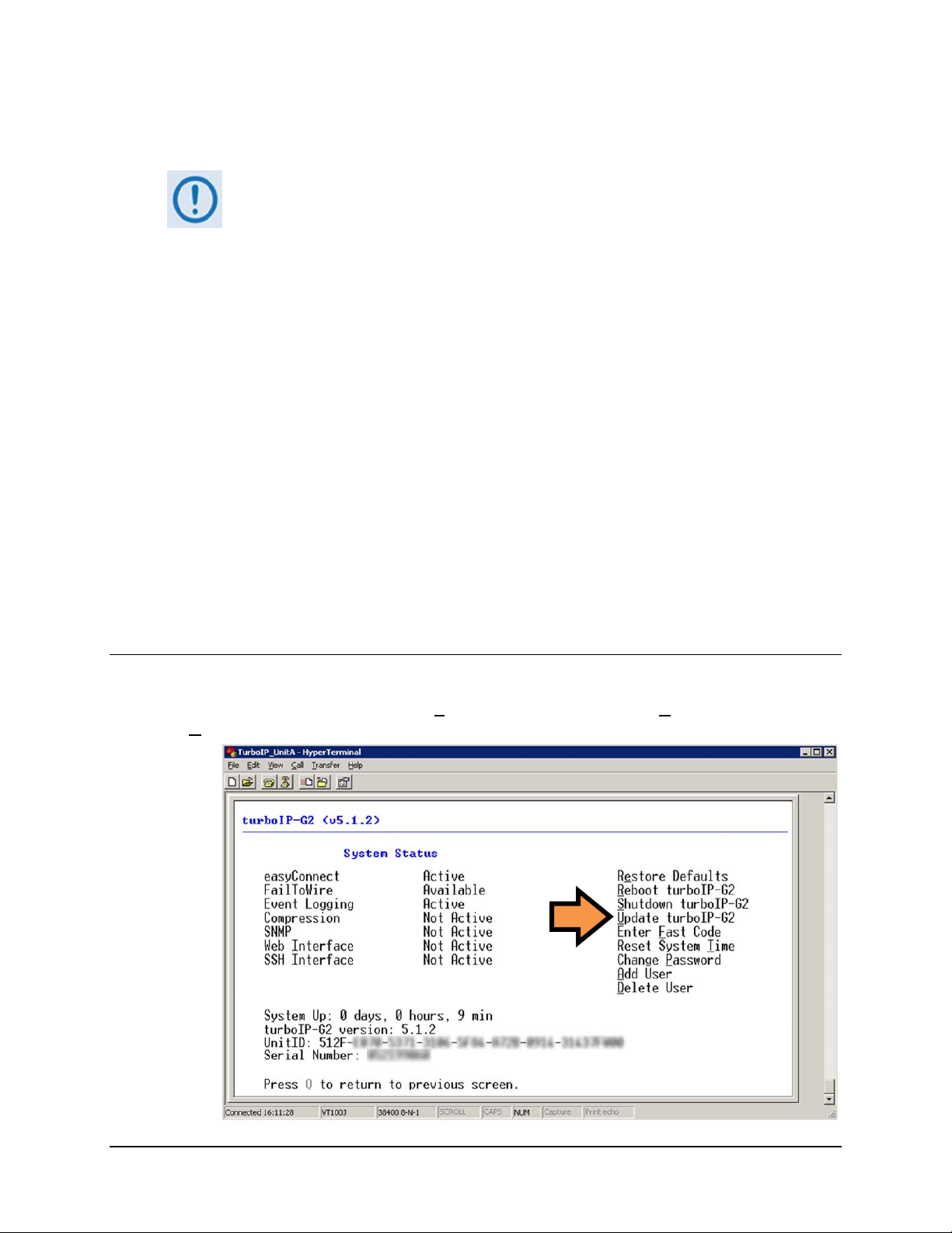
turboIP-G2 Performance Enhancement Proxy Revision 2
Configuration and Updating CD-TURBOIP-G2
4.6.2 Updating Software
Toproceedwiththesoftwareupdateprocedure,assumptionsaremadethat:
• TheturboIP‐G2isconnectedtoauser‐supplied,Windows‐basedPC,and:
o ThePC’sserialportisconnectedtotheturboIP‐G2‘CONSOLE’port.
o The PC’s Ethernet port is connected to the turboIP‐G2 ‘MGT’ Etherne
port with a user‐supplied hub, switch, or direct Ethern et cable
connection.
o The PC is running a terminal emulation program (for operation of the
turboIP‐G2 Serial Command Line Interface) and a compatible Web
browser(foroperationoftheturboIP‐G2WebServerGUI).
• The tu
rboIP‐G2’s Management IP address has been recorded using the
turboIP‐G2CommandLineInterface(CLI),andthesoftwareversionhasbeen
identifiedusingeithertheCLIortheCDM‐840WebServerInterface‘ADMIN
|SOFTWARE’page.
• Thelatestsoftwarefileshavebeendownloadedorotherwise re
ceivedfrom
Comtech EF Data and are available on the user PC in an accessible
temporaryfolder.
t
4.6.2.1 Updating via the Command Line Interface (CLI)
From the CLI Main Menu, select (7) Administrative Functions ► (1) Configurations/Actions
pdate turboIP-G2.
► U
4–20
Page 69

turboIP-G2 Performance Enhancement Proxy Revision 2
Configuration and Updating CD-TURBOIP-G2
The FTP dialogue opens. Enter the appropriate FTP Username/Password login information; the
IP address of the FTP Server; and the name of the turboIP-G2 software update file. The user is
then prompted to re-enter the FTP password. The turboIP-G2 then connects to the FTP server and
downloads the software update files.
When the download is complete, a prompt appears to confirm completion of the update, and that
the unit will need to be rebooted. The turboIP-G2 then reboots to the new software and retains all
configurations settings.
If the update process fails, the failure may be due to any of these causes:
• Incorrect username / password
• Incorrect FTP server IP address
• File does not exist
• Specified file is not a valid update file
Contact CEFD Network Product Support cdmipsupport@comtechefdata.com if
there are any difficulties or questions about upgrading the turboIP-G2.
4–21
Page 70

turboIP-G2 Performance Enhancement Proxy Revision 2
Configuration and Updating CD-TURBOIP-G2
4.6.2.2 Updating via the Web Server Graphical User Interface (GUI)
The turboIP-G2 can be upgraded by using the Web Server GUI from the user PC with an FTP
Server, locally via the ‘LAN’ port, remotely via the ‘WAN’ port, or via the dedicated ‘MGT’
port. Alternately, the turboIP-G2 can be upgraded from the user PC that is using a Web browser
to access turboIP-G2 operation.
From the Admin | Configuration page, click UUPPDDAATTEE ttuurrbbooIIPP--GG22 to continue with either
method.
4–22
Page 71

turboIP-G2 Performance Enhancement Proxy Revision 2
Configuration and Updating CD-TURBOIP-G2
4.6.2.2.1 FTP UPDATE via the Web Server GUI
Before starting the FTP Update process:
• Configure the FTP Server Home Directory to the temporary folder that was
created to store the downloaded turboIP-G2 software upgrade proprietary
image file.
•
Verify connectivity between the user PC and the turboIP-G2 with a Ping
response.
From the nested UPDATE turboIP-G2 page, click FFTTPP UUPPDDAATTEE :
Enter the appropriate FTP User/Password login information; the IP address of the FTP Server;
and the name of the turboIP-G2 software updated file. Click UUPPDDAATTEE
the software update process.
ttuurrbbo
o
IIPP--GG22
to begin
4–23
Page 72

turboIP-G2 Performance Enhancement Proxy Revision 2
Configuration and Updating CD-TURBOIP-G2
Typical for either the FTP UPDATE or UPLOAD UPDATE processes, the message “Update in
Progress” displays on the page once the update begins. As the update continues, the End User
License Agreement page displays:
The user must click AACCCCEEPPTT to continue through to completion of the software update
process.
Once the EULA is accepted, the “Update in Progress” message reappears through completion of
the software update process; at this time, the message “Update Complete! The turboIP-G2 will
now reboot” displays while the unit automatically reboots and activates the update.
The user will be required to log in to the Web Server GUI once again to resume the session.
4–24
Page 73
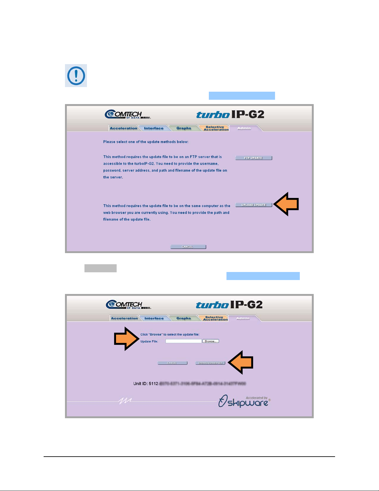
turboIP-G2 Performance Enhancement Proxy Revision 2
Configuration and Updating CD-TURBOIP-G2
4.6.2.2.2 UPLOAD UPDATE via the Web Server GUI
Before starting the UPLOAD UPDATE process, verify that the downloaded
turboIP-G2 software upgrade proprietary image file is properly available from
the temporary folder created earlier.
From the nested UPDATE turboIP-G2 page, click UUPPLLOOAADD UUPPDDAATTEE :
Click Browse... to navigate to the temporary folder created earlier to store the downloaded
software update file, and then select that file. Then, Click UUPPDDAATTEE
software update process.
As with the FTP UPDATE process, the message “Update in Progress” displays on the page
once the update begins. As the update continues, the End User License Agreement will next
ttuurrbbo
o
IIPP--GG22
to begin the
4–25
Page 74

turboIP-G2 Performance Enhancement Proxy Revision 2
Configuration and Updating CD-TURBOIP-G2
appear. Again, the user must AACCCCEEPPTT the EULA to continue through to completion of the
software update process; the “Update in Progress” message reappears through completion of the
software update process, and the message “Update Complete! The turboIP-G2 will now
reboot” then displays while the unit automatically reboots and activates the update.
The user will be required to log in to the Web Server GUI once again to resume the session.
4.6.2.2.3 T roubleshooting the Software Update Process
Typical for either the FTP UPDATE or UPLOAD UPDATE processes, if the
upgrade process fails, the failure may be due to any of these causes:
• Incorrect username / password
• Incorrect FTP server IP address
• File does not exist
• Specified file is not a valid upgrade file
Contact CEFD Network Product Support cdmipsupport@comtechefdata.com if
there are any difficulties or questions about upgrading the turboIP-G2.
The GUI will display a message page appropriate for the specific error. For example, the
following message displays if the specified FTP host is found to be invalid:
Click OOKK from any error page to return back to the previous page to retry the software update
process.
4–26
Page 75

Chapter 5. MANAGEMENT VIA THE
CLI OR WEB SERVER GUI
5.1 Important Interface Operation Notes
To use the turboIP-G2 Command Line Interface (CLI) or Web Server Graphical
User Interface (GUI), assumptions are made that:
The turboIP-G2 is connected to a user-supplied, Windows-based PC, and:
o The PC’s serial port is connected to the turboIP-G2 ‘CONSOLE’ port.
o The PC’s Ethernet port is connected to the turboIP-G2 ‘MGT’ Ethernet
port (available only on units manufactured from November 2010 to
present) with a user-supplied hub, switch, or direct Ethernet cable
connection.
o The PC is running a terminal emulation program (for operation of the
turboIP-G2 serial Command Line Interface) and a compatible Web
browser (for operation of the turboIP-G2 Web Server GUI).
The turboIP-G2 supports a basic menu-driven interface – the Command Line Interface (CLI) – that is
accessible using the ‘CONSOLE’ serial port provided on the rear panel. In addition, the Web Server
Graphical User Interface (GUI) is available via connection to the ‘MGT’ port, an RJ-45, 10/100/1000
BaseT Ethernet management interface that is dedicated for monitor and control purposes.
Each interface contains the same functionality, with one exception: the USERID and PASSWORD
are configurable only via the CLI, for obvious security reasons.
This chapter provides a high-level overview of the functionality provided by these interfaces and
references other chapters for further details.
5–1
Page 76

turboIP-G2 Performance Enhancement Proxy Revision 2
Management via the CLI or Web Server GUI CD-TURBOIP-G2
5.2 Command Line Interface (CLI)
For any new turboIP-G2 unit, the console will first display the EULA (End User License
Agreement), and a run-through of the Configuration Wizard is required. Refer to Chapter 4.
CONFIGURING AND UPDATING for detailed information regarding first-time unit
configuration.
5.2.1 CLI Login
Upon successful configuration and startup of the unit, the user is first prompted to log in with the
User ID and Password.
For example:
A successful login results in the display of the turboIP-G2 CLI Main Menu screen and the last
active session:
A note about interface appearance: The appearance of the terminal emulator-based CLI may
vary across individual user configurations. While the Main Menu screen shown above depicts use
of a HyperTerminal interface, all subsequent screen shots in this chapter depict only the CLI
screen and not the terminal emulator interface itself.
5–2
Page 77

turboIP-G2 Performance Enhancement Proxy Revision 2
Management via the CLI or Web Server GUI CD-TURBOIP-G2
5.2.2 CLI Operation using the SSH (Secure Shell) Interface
When SSH (Secure Shell) is the selected interface, the security features require that
administrative maintenance and control operations are accomplished using a Secure Shell (SSH)
Command Line Interface (CLI).
To initiate a SSH CLI session:
1. From the SSH terminal emulation program’s
folder, double-click the program filename (e.g.,
putty.exe), shortcut, icon, etc. to open the SSH
application and its configuration window.
2. (Using PuTTY as the example program) Type in
the Management IP address of the turboIP-G2 (in
the example to the right, the Host Name (or IP
Address) window) and select SSH as the
Connection Type.
3. Click Open to open the session. The session login
window will appear as per the first example
shown below left.
4. Once the login is accepted, the user is granted access to the CLI as per the second example
shown below right.
For demonstration purposes, this section uses PuTTY, a free and open source
terminal emulator application used as a serial console client for SSH, Telnet,
rlogin and raw TCP computing protocols. While the CLI Main and nested
screens will be identical across terminal emulator applications, setup may
differ slightly – the chapter assumes users’ familiarity with their preferred SSH
interface.
5–3
Page 78

turboIP-G2 Performance Enhancement Proxy Revision 2
Management via the CLI or Web Server GUI CD-TURBOIP-G2
5.2.2.1 Common Operational Features
For any CLI screen, all changes take effect immediately upon pressing the ENTER key, with the
exception of the following three changes, which require reboot of the unit:
Initial Configuration Wizard (see Chapter 4. CONFIGURATION AND UPDATING)
Restore to Factory Defaults (see Sect. )
Updating the Unit Software (See Sect. )
Most pop-up parameter configuration windows may be exited, without saving changes, by pressing
the ESC key.
Where the Entry column (provided to specify the single-keystroke ‘mnemonic’ available to execute
a command or open a nested screen) for a tabulated item is designated as [RO], this means that the
pertinent selection is a read-only parameter provided on that screen for informational purposes only.
Most screens feature, at the bottom of the screen, the message “Press Q to return to previous
screen.” Press ‘Q’ to exit from the current screen, without saving changes made there, and to return
to the previous screen.
5.2.3 CLI Main Menu Screen
Selection Entry Description Section
Configure Interfaces 1, C
Enter Management IP Address and subnet mask
Enter Bridge IP Address and subnet mask
Turn WEB Interface On/Off
Turn SSH Interface On/Off
Set LAN/WAN/Management port Link Settings
Display LAN/WAN/Management MAC address and Link Status
Configure PBR
Fail To Wire On/Off
5.2.3.1
5–4
Page 79
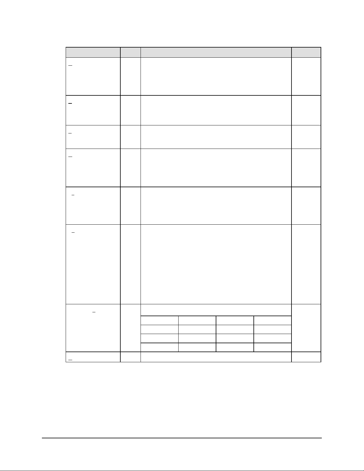
turboIP-G2 Performance Enhancement Proxy Revision 2
Management via the CLI or Web Server GUI CD-TURBOIP-G2
Selection Entry Description Section
Gateway
Configuration
Set LAN and WAN Transmission Rates
2, G
Set LAN Maximum Transfer Unit (MTU)
5.2.3.2
Set WAN Maximum Transfer Unit (MTU)
Set Congestion Control to Per-Connection or Rate Pacing, and
Error-Tolerance
Routing 3, R
Add, adjust, or delete IPv4 and IPv6 routes from system routing
5.2.3.3
table
(Route entries are only required for remote network access to the
turboIP-G2)
SNMP 4, S
Set SNMP subsystem On/Off
5.2.3.4
Set SNMP system variables such as, System Information,
Community Strings, and Trap Destination.
Optimization 5, O
Turn Compression On/Off
5.2.3.5
Turn Web Cache On/Off
Turn DRE On/Off
Turn CIFS On/Off
Clear all Optimization Stats
Selective Acceleration 6, E
Add, move, edit, and delete TCP/UDP QoS/Acceleration rules
5.2.3.6
Monitor statistics by priority
Each rule has the following variables - Source IP address/Mask,
Destination IP address/Mask, Protocol, Source Port, Destination
Port, Priority, Bandwidth, Acceleration ON/OFF, and Status.
Administrative
Functions
Displays System Status for turboIP-G2 features – easyConnect,
7, d
FailToWre, Event Logging, Compression, SNMP, Web Interface,
5.2.3.7
SSH Interface
Displays System Up Time, turboIP-G2 Version, Unit ID
Used to administer the system functions – Restore Defaults,
Reboot, Shutdown, Upgrade, Reset System Time, Change
Password, Add User, Delete User
Enable Logging, View or Clear Event Log
Display/Reset System Statistics – Avg. Compression Ratio,
Session Statistics, WAN and LAN Statistics
Save and Restore State
Command Line
Interface
8, L
Allows user to run the following commands/queries:
get help ip log
5.2.3.8
menu ping route route6
rule set snmp stats
system user tcpdump trace
Quit 9, Q
Quit the CLI and return to the session login prompt
5.2.2.1
5–5
Page 80

turboIP-G2 Performance Enhancement Proxy Revision 2
o
Management via the CLI or Web Server GUI CD-TURBOIP-G2
5.2.3.1 Configure Interfaces Screen
Selection Entry Description Section
easyConnect
Management IP
Addresses
Web User Interface
SSH User Interface
Link Settings
Advanced Options
[RO] Status only (always on) –
A
M
W Select as On/Off using ▲▼keys, press ENTER to save.
S Select as On/Off using ▲▼keys, press ENTER to save.
L
A
dd IPv4 or IPv6 Management IP Addresses
emove IPv4 or IPv6 Management IP Addresses
R
Select/display LAN, WAN or Management Link Settings:
Select using ▲▼keys, then press ENTER to set speed for each
port:
o Auto-Negotiate, 10baseT, 10baseT-FD, 100baseTx,
100baseTx-FD , 1000baseTx-FD
Displays the following [RO] information for each port:
o MAC Address
o Displays Link Status – Established, Not Established
o Speed Reported
Auto-Negotiation – Enabled, Disabled
Select I
Select F
nterface mode as Single/Double using ▲▼keys, press
ENTER to save.
ail-to-Wire as Enabled/Disabled using ▲▼keys, press
ENTER to save.
5.2.3.1.1
5.2.3.1.2
5.2.3.1.3
–
–
5–6
Page 81

turboIP-G2 Performance Enhancement Proxy Revision 2
Management via the CLI or Web Server GUI CD-TURBOIP-G2
5.2.3.1.1 Configure Interfaces | Management IP Addre ss Configura tion Screen
The Management IP Address Configuration screen allows a user to A
IP addresses. The Management IP Address is assigned to the ‘MGT’ port (available only on units
manufactured from November 2010 to present).
To add a Management IP Address, press ‘A’ – the user will be prompted for the IP Address
Version – select IPv4 or IPv6 using the ▲▼arrow keys; select the version and then press
ENTER to proceed:
For IPv4 version addresses – Enter the IP Address and Subnet Mask.
For IPv6 version addresses – Enter the IPv6 Address and Routing Prefix.
For either, press ENTER to save.
To remove a Management IP Address, press ‘R’ – the user will be prompted to specify the IP
Address Num; press ENTER to execute removal of that address.
The Interface Configuration allows a user to add or remove manageable IP Addresses:
To add a Management Address destined for the MGT (Management) Port, select
“Management”.
To add a Management IP Address that is destined for the LAN and WAN traffic ports,
select “Bridge”.
To add a manageable IP Address when PBR is enabled, and the unit is configured in
Single Interface Mode, select “Untagged VLAN”. Ensure that the VLAN number
matches the LAN or WAN PBR VLAN.
dd or Remove Management
5–7
Page 82

turboIP-G2 Performance Enhancement Proxy Revision 2
Management via the CLI or Web Server GUI CD-TURBOIP-G2
5.2.3.1.2 Configure Interfaces | Link Setting Configuration Screen
The Link Setting Configuration screen allows the user to configure the speed, duplex, and autonegotiation on the LAN, WAN, and Management ports, and displays the MAC address.
Selection Entry Description
Select setting using ▲▼keys, then press ENTER to set for each port:
LAN Link Setting L
WAN Link Setting W
Management Link
Setting
(Link current
operating
parameters)
M
[RO]
Auto-Negotiate
10baseT
10baseT-FD
100baseTx
100baseTx-FD
1000baseTx-FD
Displays the following read-only information for each port:
MAC Address
Link Status – Established, Not Established
Speed Reported
Auto-Negotiation – Enabled, Disabled
The screen will reflect the updating configuration settings upon its next access from the
Configure Interfaces screen. Information on the Link Setting, MAC Address, reported speed,
and auto-negotiation are updated and provided here on a read-only basis.
5–8
Page 83

turboIP-G2 Performance Enhancement Proxy Revision 2
Management via the CLI or Web Server GUI CD-TURBOIP-G2
5.2.3.1.3 Configure Interfaces | Advanced Options Screen
The Advanced Interface Configuration screen allows the turboIP-G2 to be configured in an out of
bound network.
Selection Entry Description
Interface Mode I
Fail To Wire
(Data pass through)
PBR Support [RO] Displays PBR Support as On/Off
LAN IP [RO] Displays LAN IP Address /Subnet Mask /Next Hop
WAN IP [RO] Displays WAN IP Address/Subnet Mask/Next Hop
Select as Single/Double using ▲▼keys, press ENTER to save.
LAN VLAN ID and WAN VLAN ID
F Select as Enabled/Disabled using ▲▼keys, press ENTER to save.
The unit’s LAN port is required to be connected to the router or device handling the internal
routing of packets. The Interface Mode must be set to Single, and PBR Support must be turned
On.
Configure the LAN and WAN interfaces to correspond to the networks assigned to the userprovided router. Single mode uses VLAN to segregate the LAN and WAN networks.
Ensure that the router that is connected to the turboIP-G2 LAN port has two (2) virtual interfaces
available.
5–9
Page 84

turboIP-G2 Performance Enhancement Proxy Revision 2
Management via the CLI or Web Server GUI CD-TURBOIP-G2
5.2.3.2 Gateway Configuration Screen
The Gateway Configuration screen allows a user to configure and LAN and WAN rates and
MTU. Also this screen allows the user to configure Congestion Control. A user may need to
configure a MTU to match the network’s MTU.
Allowing larger MTUs than what Ethernet devices can support may result in bad
network performance.
Selection Entry Description Section
Set LAN Transmission Rate (15 Mbps FAST Option) – Enter a
LAN L
(LAN) Maximum
Transfer Unit (MTU)
WAN W
(WAN) Maximum
Transfer Unit (MTU)
Congestion Control o
number followed by a space and 'bps', 'kbps' or 'Mbps'. Range is ≥
10 kbps and ≤ 15 Mbps.
M Specify MTU size, in bytes (default is 1500) –
Set WAN Transmission Rate (15 Mbps FAST Option) – Enter a
number followed by a space and 'bps', 'kbps' or 'Mbps'. Range is ≥
10 kbps and ≤ 15 Mbps.
x Specify MTU size, in bytes (default is 1500) 5.2.3.2.2
Select as Per-Connection,Rate Pacing, or Error Tolerance using
▲▼keys, press ENTER to save.
–
5.2.3.2.1
5.2.3.2.3
5–10
Page 85

turboIP-G2 Performance Enhancement Proxy Revision 2
Management via the CLI or Web Server GUI CD-TURBOIP-G2
5.2.3.2.1 W A N Transmission Rate
Set the maximum bandwidth available for TCP traffic on the WAN interface (a number, followed
by a space and 'bps', 'kbps' or 'Mbps'). Must be ≥ 10 kbps and ≤ 15 Mbps. Setting the WAN
transmission rate in excess of available bandwidth could lead to packet loss and degraded
performance.
Set the maximum bandwidth available for TCP traffic on the WAN interface (a number, followed
by a space and 'bps', 'kbps' or 'Mbps'). Must be ≥ 10 kbps and ≤ 45 Mbps. Setting the WAN
transmission rate in excess of available bandwidth could lead to packet loss and degraded
performance.
Set the maximum bandwidth available for TCP traffic on the WAN interface (a number, followed
by a space and 'bps', 'kbps' or 'Mbps'). Must be ≥ 10 kbps and ≤ 155 Mbps. Setting the WAN
transmission rate in excess of available bandwidth could lead to packet loss and degraded
performance.
For a mix of TCP / non-TCP traffic, use these settings to limit the bandwidth for TCP traffic:
Example 1 – A pair of turboIP-G2s is used to accelerate TCP traffic on a satellite link
where satellite Modem A has a TX data rate of 12 Mbps, and satellite Modem B has a TX
data rate of 2048 kbps. Use WAN setting 12 Mbps for turboIP-G2 A, and 2048 kbps for
turboIP-G2 B.
Example 2 – A turboIP-G2 is in place at a hub where there are three outbound satellite
links to three separate remotes with the following links:
Link A – Hub 4 Mbps Outbound, Remote A – 1536 kbps Inbound
Link B – Hub 3 Mbps Outbound, Remote B – 1024 kbps Inbound
Link A – Hub 2 Mbps Outbound, Remote C – 768 kbps Inbound
The Hub turboIP-G2 WAN is set to 9 Mbps to equal the total available Outbound
bandwidth (4 + 3 + 2). In this example, create Selective Acceleration Rules to limit the
bandwidth to match the Outbound TX data rate for each Remote. Set the Remote turboIP-
G2 WAN setting to the Inbound TX data rate to the Hub.
5.2.3.2.2 Maximum Transfer Unit (MTU)
The MTU setting enables the turboIP-G2 to better support interoperability with other IP devices
requiring less than 1500-byte TCP payloads. The MTU default setting is 1500 bytes.
5.2.3.2.3 Congestion Control
The turboIP-G2 supports three congestion control algorthim modes:
Per-Connection Mode – The Per-Connection Mode mirrors the standard TCP
congestion control algorthim. If any loss is detected, the window will be reduced by half.
It should be used to support dynamic bandwidth paths, where the bandwidth may be
different for any of the paths being accelerated by the turboIP-G2. This mode will
interpret any loss as congestion.
5–11
Page 86

turboIP-G2 Performance Enhancement Proxy Revision 2
Management via the CLI or Web Server GUI CD-TURBOIP-G2
Rate Pacing Mode – The Rate Pacing Mode will always try to achieve the WAN Rate. It
should be used when bandwidth path for accelerated TCP traffic remains constant with
the set WAN Transmission Rate. In Rate Pacing Mode, the turboIP-G2 meters out bursty
traffic at a rate not to exceed the configured transmission rate of the satellite channel.
This prevents the satellite channel from becoming congested and will maximize
accelerated TCP throughput to match the set WAN Transmission Rate.
Error Tolerance Mode – The Error Tolerance Mode is similar to Per-Connection Mode,
with the exception that the TCP windows will not be reduced unless loss is more than
1/12 of the windows. Also Error Tolerance Mode supports ECN (Explicit Congestion
Notification) if both TurboIP supports this feature. ECN is an end to end notification of
network congestion without dropping packets.
Error Tolerance Mode should be used to support dynamic bandwidth paths, where the
bandwidth may be different for any of the paths being accelerated by the turboIP-G2.
This mode only should be used if ECN is enabled on the bottleneck link.
5–12
Page 87

turboIP-G2 Performance Enhancement Proxy Revision 2
Management via the CLI or Web Server GUI CD-TURBOIP-G2
5.2.3.3 Routing Screen
Route entries are needed only to allow access to the turboIP-G2 from an outside
network (using the Web or SNMP IP interface).
Select 1 to access the IPv4 Routing Table, or 2 to access the IPv6 Routing Table.
5.2.3.3.1 Routing | IPv4 Routing Table Screen
Per the example here, the Destination is set to all IP Addresses, the Prefix is set to all Netmasks,
and the Next Hop address is 192.1.1.1.
To add an IPv4 route, press ‘A’ – the user will first be prompted to enter the Dest Address,
Subnet Mask, and Net Hop address; press ENTER when done. The user will next be
prompted to specify the Route Status – select Active or Not in Service using the ▲▼ keys,
and then press ENTER to save. IPv4 route numbers are automatically assigned in the order
they are created.
To remove an IPv4 route, press ‘R’ – the user will be prompted to specify the IP Address
(Route) Num; press ENTER to execute removal of that route.
To edit an IPv4 route, press ‘E’ – the user will first be prompted to specify the Route Num
to edit; then, edit the Dest Address, Subnet Mask, and Next Hop address as desired. Finally,
edit the Route Status as Active or Not in Service. Press ENTER to save any changes made.
5–13
Page 88

turboIP-G2 Performance Enhancement Proxy Revision 2
Management via the CLI or Web Server GUI CD-TURBOIP-G2
5.2.3.3.2 Routing | IPv6 Routing Table Screen
Per the example here, the Destination is set to all IP Addresses, the Prefix is set to all Prefixes,
and the Next Hop address is 2001:db8::2.
To add an IPv6 route, press ‘A’ – the user will first be prompted to enter the Dest Address,
Routing Prefix, and Net Hop address; press ENTER when done. The user will next be
prompted to specify the Route Status: Select as Active or Not in Service using the ▲▼
keys, and then press ENTER to save. IPv6 route numbers are automatically assigned in the
order they are created.
To remove an IPv6 route, press ‘R’ – the user will be prompted to specify the Route Num;
press ENTER to execute removal of that route.
To edit an IPv6 route, press ‘E’ – the user will first be prompted to specify the Route Num
to edit; then, edit the Dest Address, Routing Prefix, and Next Hop address as desired.
Finally, edit the Route Status as Active or Not in Service. Press ENTER to save any
changes made.
5–14
Page 89

turboIP-G2 Performance Enhancement Proxy Revision 2
Management via the CLI or Web Server GUI CD-TURBOIP-G2
5.2.3.4 SNMP Screen
By default, SNMP (Simple Network Management Protocol) is not initially enabled or configured
for operation. Initial access to the SNMP screen prompts the user to run the SNMP Configuration
Wizard:
Press ‘R’ to Run the Configuration Wizard. User prompts appear in the order presented here:
5.2.3.4.1 SNMP Configuration Wizard
Prompt Response
Which SNMP version would you like to use? Select ‘2’ for SNMP v2, or ‘3’ for SNMP v3.
If SNMP v2 is selected, proceed as follows:
SNMP sysName: sysName: Enter a desired name for the system.
SNMP sysLocation: sysLocation: Enter a desired location for the system.
SNMP sysContact: sysContact: Enter a desired contact for the system.
SNMP Trap Destination IP Address: Trap IP: Enter the IP Address xxx.xxx.xxx.xxx
Read (Read-only) Community: Enter a desired name.
SNMP v2 Community Strings:
If SNMP v3 is selected, proceed as follows:
Username: Enter a desired username.
Would you like to use Authentication? Press 1 or Y for Yes, 2 or N for No
If Yes is selected for Authentication
Auth. Passphrase:
Set (Read-Write) Community: Enter a desired name.
Trap (Notification) Community: Enter a desired name.
Enter a passphrase that is from 8 to 255 characters long.
Would you like to use Privacy? Press 1 or Y for Yes, 2 or N for No
If Yes is selected for Privacy
Priv. Passphrase:
Enter a passphrase that is from 8 to 255 characters long.
5–15
Page 90

turboIP-G2 Performance Enhancement Proxy Revision 2
Management via the CLI or Web Server GUI CD-TURBOIP-G2
Typical for the SNMP v2 or SNMP v3 Configuration Wizard, continue as follows:
Would you like to enable SNMP?
You have almost finished the SNMP
Configuration Wizard.
Once the SNMP Configuration Wizard closes, the appearance of the SNMP screen differs
depending on the SNMP for which the CLI has been configured.
5.2.3.4.2 SNMP Screen (SNMP v2)
The screen example shown here depicts the SNMP screen as defined by a typical SNMPv2 user.
Press 1 or E to Enable SNMP
Press 2 or D to Disable SNMP
Press 1 or S to Save SNMP Changes
Press 2 or C to Cancel SNMP Changes
Selection Entry Description
SNMP S Select as On/Off using ▲▼keys, press ENTER to save.
N
ame N As required.
SYSTEM
INFORMATION
COMMUNITY
NAMES
Trap Destination IP Address T IP address destination for traps.
Run SNMP Configuration Wizard R
Location L As required.
Contact C As required.
Read-W
rite Access W SNMP SET Community String.
Read-Only Access O SNMP GET Community String.
Notification Access A SNMP Trap Community String.
Select to erase and/or reconfigure all SNMP settings or to
change to the alternate SNMP Version (SNMP v2 or v3).
5–16
Page 91

turboIP-G2 Performance Enhancement Proxy Revision 2
Management via the CLI or Web Server GUI CD-TURBOIP-G2
5.2.3.4.3 SNMP Screen (SNMP v3)
With SNMP v3 selected, no configuration settings are displayed other than the following
selections:
Selection Entry Description
SNMP S Select as On/Off using ▲▼keys, press ENTER to save.
Run SNMP Configuration
Wizard
Select to erase and/or reconfigure all SNMP settings or to change to
R
the alternate SNMP Version (SNMP v2 or v3).
5–17
Page 92

turboIP-G2 Performance Enhancement Proxy Revision 2
Management via the CLI or Web Server GUI CD-TURBOIP-G2
5.2.3.5 Optimization Screen
WAN Optimization is available with units manufactured from November 2010 to
the present date.
Selection Entry Description
Compression C
Web Cache W
DNS (Domain Name
System) S
Clear Cache e Using ▲▼keys, select Yes to clear Web Cache, No to abort command
DRE (Data
Redundancy
Elimination)
Clear Cache
CIFS (Common Internet
File System)
Clear All Optimization
Stats
erver
Select as On/Off using ▲▼keys, press ENTER to save.
Turning Compression On enables Data and Header Compression.
Select as On/Off using ▲▼keys, press ENTER to save.
WebCache enables caching only pertaining to HTTP/HTTPS protocol on the
LAN side. (Note – DNS Server must be configured first.)
S Add a DNS Server.
Select as Off, Persistent-LZ, or DRE + Persistent-LZ using ▲▼keys, press
ENTER to save.
D
Persistent-LZ will compress any compressible data.
DRE + Persistent-LZ will eliminate redundancies found within data; also, if
the data is compressible it will compress the data
l
Using ▲▼keys, select Yes to clear DRE Cache, No to abort command
I
Select as On/Off using ▲▼keys, press ENTER to save.
Using ▲▼keys, select Yes to clear Optimization Stats and refresh screen, No
A
to abort command
5–18
Page 93

turboIP-G2 Performance Enhancement Proxy Revision 2
Management via the CLI or Web Server GUI CD-TURBOIP-G2
5.2.3.6 Selective Acceleration Screen
Selection Entry Description Section
View/Edit Rules 1, V Select to view, edit, add, or remove Selection Acceleration Rule. 5.2.3.6.1
Statistics 2, S Select to view Selection Acceleration Statistics by Priority. 5.2.3.6.2
5–19
Page 94

turboIP-G2 Performance Enhancement Proxy Revision 2
Management via the CLI or Web Server GUI CD-TURBOIP-G2
5.2.3.6.1 Selective Acceleration | View/Edit Rules Screen
Selection Entry Description Sect.
Insert Rule I Insert the rule before selected rule. –
Edit Rule E Modify the selected rule to change its variables. 5.2.3.6.1.1
Remove Rule R Remove one selected rule at a time. –
Move Rule M Move the selected rule to higher or lower order of rule ID. –
First F Go to the first screen where the rule ID at #. –
Last L Go to the last screen of the rule table at #. –
Scroll Up U Scroll up one screen at a time. –
Scroll Down D Scroll down one screen at a time. –
Selective Acceleration Rules can be applied to any IP traffic through the
turboIP-G2; assigning a Priority (1-8) and Bandwidth limit to IP traffic that falls
within the Rule.
For any traffic that meets the criteria of more than one Rule, the first (lowest #)
Rule will be applied.
The default acceleration rule creates one TCP rule for any TCP traffic, a bridge
rule for any other traffic that will not be accelerated, and a default rule is
applied to all traffic not meeting these two defined rules; the default rule
cannot be edited or removed.
5–20
Page 95

turboIP-G2 Performance Enhancement Proxy Revision 2
Management via the CLI or Web Server GUI CD-TURBOIP-G2
5.2.3.6.1.1 Selective Acceleration | View/Edi t Rules | Edit Rule Screen
Selection Entry Description
IP Version V
Source Address Mask S
Destination Address Mask D
Priority P
Protocol r Select as TCP, UDP, or Any using ▲▼keys, press ENTER to save.
Select as ANY, IPv4, or IPv6 using ▲▼keys, press ENTER to save.
Default is ANY.
Default 0.0.0.0 (wild card – applied to any IPv4 address).
Default ::/0 (wild card – applied to any IPv6 address).
Default 0.0.0.0 (wild card – applied to any IPv4 address).
Default ::/0 (wild card – applied to any IPv6 address).
Select as 1 through 8 (with 1 being highest priority), Drop, or Bridge using
▲▼keys, press ENTER to save.
Default __ (no entry = wild card – applied to any port).
Source Port Start / End o
Destination Port Start / End e
Maximum Bandwidth M
Acceleration A
Status t
Cancel Changes C Select to cancel all changes made on this screen
Enter Start and End Port numbers for a range of ports.
Enter same port for Start and End for a single port.
Default __ (no entry = wild card – applied to any port)
Enter Start and End Port numbers for a range of ports.
Enter same port for Start and End for a single port.
Depending on units FAST Options:
155 WAN Rate Default is 155000 kbps.
45 WAN Rate Default is 45000 kbps.
15 WAN Rate Default is 15000 kbps.
Select as On/Off using ▲▼keys, press ENTER to save:
Select On to accelerate TCP traffic within this Rule.
Select Off to bypass acceleration for TCP traffic within this Rule.
Select as Active/Not in Service using ▲▼keys, press ENTER to save:
Select Active for Rule to be applied.
Select Not in Service to have Rule not applied.
5–21
Page 96

turboIP-G2 Performance Enhancement Proxy Revision 2
Management via the CLI or Web Server GUI CD-TURBOIP-G2
5.2.3.6.2 Selective Acceleration | Statistics Screen
Selective Acceleration Statistics are sorted by Priority, not by rule number. The Priority 8 Statistics
include any Default Rule traffic, plus any traffic within a Rule having a Priority of 8.
All Statistics except Current Rate and Accelerated Sessions are cumulative from the last instance of
clearing Statistics.
Note the following:
Statistic Description
Packets Sent Packets sent for this Priority
Packets Dropped Packets Dropped for this Priority
Cur Rate (kbps) Current Rate in kbps for this Priority
Avg Rate (kbps) Avg Rate in kbps for this Priority
Max Rate (kbps) Max Rate in kbps for this Priority
Accel Sessions Current Accelerated Sessions for this Priority
5–22
Page 97

turboIP-G2 Performance Enhancement Proxy Revision 2
Management via the CLI or Web Server GUI CD-TURBOIP-G2
5.2.3.7 Administrative Functions Screen
About Administrator Functions: The Administrator changes passwords, and
adds and deletes users only through the Serial CLI and SSH (Secure Shell)
interfaces via the ‘admin’ login. Normal users cannot see or edit these
settings.
The Administrator specifies whether an account is an Administrator or Normal
User.
The option to change usernames is not available through the Web Server GUI. To
accomplish this, the Administrator deletes the user account and then recreates it
with a new username. If the Administrator tries to add more than the maximum
number of five (5) user accounts, an error mes sage is displa yed.
See Chapter 4. CONFIGURATION and UPDATING for detailed information about
the use of key Administrator Function s.
Selection Entry Description Sect.
Configuration/Actions 1, C Select to perform administrative functions 5.2.3.7.1
Event Log 2, E Select to view or clear Event Log 5.2.3.7.2
Statistics 3, S Select to view or clear statistics 5.2.3.7.3
Save/Restore State 4, a Select to save or restore unit configurations 5.2.3.7.4
5–23
Page 98

turboIP-G2 Performance Enhancement Proxy Revision 2
Management via the CLI or Web Server GUI CD-TURBOIP-G2
5.2.3.7.1 Administrative Functions | Configurations/Actions Screen
The information organized under the System Status column at the left-hand side of this screen
provides read-only information about the unit; i.e., the current operating status of its available
operational features, physcial unit identifying information, etc.:
Item Description
easyConnect Active (always enabled)
FailToWire Available/Not Available – indicates presence of Fail to Wire Hardware
Event Logging Active/Not Active
Compression Active/Not Active
SNMP Active/Not Active
Web Interface Active/Not Active
SSH Interface Active/Not Active
System Up Displays System Up Time in days/hours/minutes
turboIP-G2 version Current SW Version
Unit ID Unit ID #
Serial Number Unit Serial Number
5–24
Page 99

turboIP-G2 Performance Enhancement Proxy Revision 2
Management via the CLI or Web Server GUI CD-TURBOIP-G2
The right-hand side of the Configuration/Actions screen provides a number of configuration
actions:
Selection Entry Description Sect.
Restore Defaults e Restore Factory Default settings (SSH/CLI Only function) –
Reboot turboIP-G2 R Manual Reboot –
Shutdown turboIP-G2 S Manual Shutdown –
Upgrade turboIP-G2 U Upgrade turboIP-G2 Software 4.6
Enter FAST Code F
Reset System Time T Time reset (SSH/CLI Only function) 4.5.1.3
Change Password P Change current Password (SSH/CLI Only function) 4.5.1.2
Add User A Select to add new user account (SSH/CLI Only functiaon) 4.5.1.1
Delete User D Select to delete user account (SSH/CLI Only function) –
Enter the 20-digit FAST Access Code, obtained from Comtech EF Data
Customer Support, used to unlock optional FAST features
–
5.2.3.7.2 Administrative Functions | Event Log Configuration Screen
Selection Entry Description Sect.
Event Logging L Select as On/Off using ▲▼keys, press ENTER to save. –
View log V Select to view log
Clear log C Select to clear log –
5.2.3.7.2.1
5–25
Page 100

turboIP-G2 Performance Enhancement Proxy Revision 2
Management via the CLI or Web Server GUI CD-TURBOIP-G2
5.2.3.7.2.1 Administrative Functions | Event Log Configuration |View Log Screen
Selection Entry Description
Top T Go to the top entry in the Event Log
Scroll Up U Scroll the display up a screen
Scroll Down D Scroll the display down a screen
End E Go to the bottom entry in the Event Log
5–26
 Loading...