

Page 1

y
™
v4.0
turboIP
TCP/IP Performance Enhancement Prox
User Guide
Part Number MN/TURBOIP.IOM
Revision 6
Page 2

ii
Page 3

turboIP
TCP/IP Performance Enhancement Proxy
Comtech EF Data is an ISO 9001
Registered Company
™
v4.0
User Guide
MN/TURBOIPv4.0.IOM
Revision 6
June 20, 2006
Page 4

CUSTOMER SUPPORT
Contact the Comtech EF Data Customer Support Department for:
Product support or training
Information on upgrading or returning a product
Reporting comments or suggestions concerning manuals
Contact Customer Support using any of the following methods:
Mail: Comtech EF Data
Email: service@comtechefdata.com
Customer Support Department
2114 West 7th Street
Tempe, Arizona 85281 USA
Phone: 480.333.2200 (Main Comtech EF Data Number)
480.333.4357 (Customer Support Desk)
Fax: 480.333.2161
Internet:
www.comtechefdata.com
To return a Comtech EF Data product (in-warranty and out-of-warranty) for repair or
replacement:
1. Request a Return Material Authorization (RMA) number from the Comtech EF Data
Customer Support Department.
2. Be prepared to supply the Customer Support representative with the model number,
serial number, and a description of the problem.
3. To ensure that the product is not damaged during shipping, pack the product in its
original shipping carton/packaging.
4. Ship the product back to Comtech EF Data. (Shipping charges should be prepaid.)
For more information regarding the warranty policies, see Warranty Policy, p. ix.
Page 5

Table of Contents
CHAPTER 1. OVERVIEW ....................................................................................................1-1
1.1 Introduction ..........................................................................................................................1-1
1.2 TCP/IP Performance Limitations..........................................................................................1-3
1.3 TCP/IP Performance Enhancement Proxy ..........................................................................1-3
1.4 Selective Acceleration..........................................................................................................1-4
1.5 Data and Header Compression ...........................................................................................1-5
1.6 turboIP Physical Description and Specifications..................................................................1-6
CHAPTER 2. FAIL TO WIRE..................................................................................................2-1
2.1 Description ...........................................................................................................................2-1
2.2 Fail to Wire Board Operation ...............................................................................................2-1
2.3 Fail to Wire Board Installed..................................................................................................2-2
2.4 No Fail to Wire Board Installed ............................................................................................2-4
CHAPTER 3. EASYCONNECT™..............................................................................................3-1
3.1 easyConnect™ ON ..............................................................................................................3-1
3.2 Important easyConnect™ Notes...........................................................................................3-2
CHAPTER 4. CONFIGURING TURBOIP™ ........................................................................4–1
4.1 Important Configuration Notes ......................................................................................4–1
4.2 Required Equipment List...............................................................................................4–1
4.3 User Interfaces..............................................................................................................4–2
iii
Page 6

turboIPv4.0 Revision 6
Getting Started MN/TURBOIPv4.0.IOM
4.4 Configuration Wizard.....................................................................................................4–3
4.4.1 End User License Agreement (EULA) .........................................................................4–4
4.4.2 Configuration Wizard turboIP V4.0 - Summary.......................................................... 4–5
4.4.2.1 Configuration Wizard turboIP V4.0 - User Accounts ...........................................4–7
4.4.2.3 Configuration Wizard turboIP V4.0 – Network Settings for Remote Access .....4–9
4.4.2.4 Configuration Wizard turboIP V4.0 – WAN Transmission Rate.......................4–10
4.4.2.5 Configuration Wizard turboIP V4.0 – DoD Banner ..........................................4–11
4.4.2.6 Configuration Wizard turboIP V4.0 – Web Interface........................................4–12
4.4.2.7 Configuration Wizard turboIP V4.0 – SNMP....................................................4–13
4.5 Menus and Functions - Summary ...............................................................................4–16
4.5.1 CLI - Log In.........................................................................................................4–18
4.5.2 CLI - Configure Interface Menu ..........................................................................4–19
4.5.3 CLI - Gateway Configuration Menu ....................................................................4–20
4.5.3.1 WAN Transmission Rate ................................................................................4–20
4.5.3.2 Maximum Transfer Unit (MTU) .......................................................................4–21
4.5.3.3 Compression ...................................................................................................4–21
4.5.3.4 Congestion Control.......................................................................................... 4–21
4.5.4 CLI - Route Configuration Menu........................................................................4–22
4.5.5 CLI - SNMP Configuration Menu SNMP V2 CLI Menu Display........................ 4–23
4.5.6 CLI - Selective Acceleration Menu ....................................................................4–25
4.5.7 CLI - Administrative Functions Menu ................................................................4–29
4.5.8 Web – Log In .......................................................................................................4–36
4.5.9 Web – Acceleration page ....................................................................................4–37
4.5.10 Web – Interface page ..........................................................................................4–38
4.5.11 Web – Routes page.............................................................................................4–39
4.5.12 Web – Selective Acceleration page.....................................................................4–40
4.5.13 Web – Admin page..............................................................................................4–42
4.6 Upgrade turboIP™ ......................................................................................................4–44
4.6.1 CLI - Upgrade turboIP ........................................................................................4–45
4.6.2 Web - Upgrade turboIP ......................................................................................4–46
4.6.2.1 Web - FTP Upgrade .........................................................................................4–47
4.6.2.2 Web - Upload Upgrade ...................................................................................4–48
iv
Page 7

turboIPv4.0 Revision 6
Getting Started MN/TURBOIPv4.0.IOM
CHAPTER 5. SNMP .............................................................................................................5-1
5.1 MIBII Support .......................................................................................................................5-1
5.2 Private MIB Support.............................................................................................................5-1
5.2.1 turboIPv3GatewayConfiguration ...........................................................................5–3
5.2.2 turboIPv3Interface .................................................................................................5–6
5.2.3 turboIPv3Route .....................................................................................................5–6
5.2.4 turboIPv3SelectiveAcceleration.............................................................................5–7
5.2.5 turboIPv3QoSStatisticsTable ..............................................................................5–10
5.2.6 turboIPv3Compression........................................................................................5–12
5.2.7 turboIPv3Admin...................................................................................................5–12
5.2.8 turboIPv3AdminInfo.............................................................................................5–13
5.2.9 turboIPv3EventLog..............................................................................................5–13
5.2.10 turboIPv3Statistics...............................................................................................5–14
5.2.11 turboIPv3FailToWire............................................................................................5–16
5.2.12 turboIPv3HTTP....................................................................................................5–16
5.2.13 turboIPv3Notifications .........................................................................................5–17
5.2.14 turboIPv3ProcessNotifications ............................................................................5–18
CHAPTER 6. COPY PROTECTION.....................................................................................6-1
CHAPTER 7. SAMPLE CONFIGURATIONS .......................................................................7-1
7.1 Sample Configurations Introductions ...................................................................................7-1
7.2 Point-to-Point Configuration.................................................................................................7-2
7.3 Point-to-Multipoint Configuration..........................................................................................7-3
7.4 Hub-Spoke Configuration.....................................................................................................7-4
7.5 Dynamic Bandwidth Configuration.......................................................................................7-6
CHAPTER 8. END USER LICENSE AGREEMENT............................................................8–1
v
Page 8
turboIPv4.0 Revision 6
Getting Started MN/TURBOIPv4.0.IOM
ABOUT THIS MANUAL
This manual provides installation and operation information for Comtech EF Data’s turboIP™
Performance Enhancement Proxy. This document is intended for network designers and operators
responsible for the operation and maintenance of the turboIP™.
CONVENTIONS AND REFERENCES
CAUTIONS AND WARNINGS
Indicates information critical for proper equipment function.
IMPORTANT
CAUTION
Indicates a hazardous situation that, if not avoided, may result in minor or moderate
injury. CAUTION may also be used to indicate other unsafe practices or risks of
property damage.
Indicates a potentially hazardous situation that, if not avoided, could result in
WARN ING
death or serious injury.
METRIC CONVERSION
Metric conversion information is located on the inside back cover of this manual. This
information is provided to assist the operator in cross-referencing non-metric to metric
conversions.
TRADEMARKS
All product names mentioned in this manual may be trademarks or registered trademarks of their
respective companies and are hereby acknowledged.
REPORTING COMMENTS OR SUGGESTIONS CONCERNING THIS MANUAL
Comments and suggestions regarding the content and design of this manual will be appreciated.
To submit comments, please contact the Comtech EF Data Customer Support Department.
vi
Page 9

turboIPv4.0 Revision 6
Getting Started MN/TURBOIPv4.0.IOM
EMC COMPLIANCE
This is a Class A product. In a domestic environment, it may cause radio interference that
requires the user to take adequate protection measures.
EN55022 COMPLIANCE
This equipment meets the radio disturbance characteristic specifications for information
technology equipment as defined in EN55022
EN50082-1 COMPLIANCE
This equipment meets the electromagnetic compatibility/generic immunity standard as defined in
EN50082-1.
.
FEDERAL COMMUNICATIONS COMMISSION (FCC)
This equipment has been tested and found to comply with the limits for a Class A digital device,
pursuant to Part 15 of the FCC rules. These limits are designed to provide reasonable protection
against harmful interference when the equipment is operated in a commercial environment.
This equipment generates, uses, and can radiate radio frequency energy. If not installed and used
in accordance with the instruction manual, it may cause harmful interference to radio
communications. Operation of this equipment in a residential area is likely to cause harmful
interference, in which case users are required to correct the interference at their own expense.
Note: To ensure compliance, properly shielded cables for DATA I/O shall be used.
More specifically, these cables shall be shielded from end to end, ensuring a
continuous shield.
HIGHLIGHTS OF THIS REVISON
Revised Chapter 8. End User License Agreement
vii
Page 10

turboIPv4.0 Revision 6
Getting Started MN/TURBOIPv4.0.IOM
Safety Compliance
EN 60950
Applicable testing is routinely performed as a condition of manufacturing on all units to ensure
compliance with safety requirements of EN60950.
This equipment meets the Safety of Information Technology Equipment specification as defined
in EN60950.
LOW VOLTAGE DIRECTIVE (LVD)
The following information is applicable for the European Low Voltage Directive (EN60950):
<HAR> Type of power cord required for use in the European Community.
CAUTION: Double-pole/Neutral Fusing.
!
ACHTUNG: Zweipolige bzw. Neutralleiter-Sicherung.
International Symbols:
Symbol Definition Symbol Definition
Alternating Current.
Fuse.
Protective Earth.
Chassis Ground.
Note: For additional symbols, refer to “Cautions” listed earlier in this preface.
viii
Page 11

turboIPv4.0 Revision 6
Getting Started MN/TURBOIPv4.0.IOM
WARRANTY POLICY
This Comtech EF Data product is warranted against defects in material and workmanship for a
period of two years from the date of shipment. During the warranty period, Comtech EF Data
will, at its option, repair or replace products that prove to be defective.
For equipment under warranty, the customer is responsible for freight to Comtech EF Data and all
related customs fees, taxes, tariffs, insurance, etc. Comtech EF Data is responsible for the freight
charges only for return of the equipment from the factory to the customer. Comtech EF Data will
return the equipment by the same method (i.e., Air, Express, Surface) as the equipment was sent
to Comtech EF Data.
LIMITATIONS OF WARRANTY
The foregoing warranty shall not apply to defects resulting from improper installation or
maintenance, abuse, unauthorized modification, or operation outside of environmental
specifications for the product, or, for damages that occur due to improper repackaging of
equipment for return to Comtech EF Data.
No other warranty is expressed or implied. Comtech EF Data specifically disclaims the implied
warranties of merchantability and fitness for particular purpose.
EXCLUSIVE REMEDIES
The remedies provided herein are the buyer's sole and exclusive remedies. Comtech EF Data shall
not be liable for any direct, indirect, special, incidental, or consequential damages, whether based
on contract, tort, or any other legal theory.
DISCLAIMER
Comtech EF Data has reviewed this manual thoroughly in order to provide an easy-to-use guide
to the equipment. All statements, technical information, and recommendations in this manual and
in any guides or related documents are believed reliable, but the accuracy and completeness
thereof are not guaranteed or warranted, and they are not intended to be, nor should they be
understood to be, representations or warranties concerning the products described. Further,
Comtech EF Data reserves the right to make changes in the specifications of the products
described in this manual at any time without notice and without obligation to notify any person of
such changes.
If you have any questions regarding the equipment or the information in this manual, please
contact the Comtech EF Data Customer Support Department.
ix
Page 12

turboIPv4.0 Revision 6
Getting Started MN/TURBOIPv4.0.IOM
This page is intentionally left blank.
x
Page 13
turboIP™
Performance
Enhancement
Proxy
1.1 INTRODUCTION
This User Guide provides an overview of Comtech EF Data’s turboIP™ Performance
Enhancement Proxy along with instructions on how to configure the turboIP™, starting
from factory default settings, so that it is passing traffic within minutes. It is assumed that
the reader is familiar with general IP networking principles.
1.1.1 DEFINITIONS
Term Meaning
Bridge
Byte
CLI (Command
Line Interface)
Compression
Datagram
easyConnect™
Fail to Wire (FTW)
Frame
Gateway
HTTP (Hyper Test
Transfer Protocol)
kbps (kilobits per
second)
Chapter 1. Overview
In this document, this term refers to a network element that receives
frames from one network interface and forwards them in the direction of
their destination based on their link layer addresses.
Eight bits (see Octet).
The user interface of the turboIP system that is available via the serial port.
A turboIP feature that will attempt both Header and Payload Compression
on all accelerated TCP sessions.
The portion of a PDU that corresponds to the network layer and higher,
that is, that portion that is transferred end to end between IP hosts on
different networks.
The feature of the turboIP system that allows it to operate as a bridge.
turboIP feature that will allow all traffic to automatically bypass the turboIP
in the event of a failure.
A link layer PDU.
A network device used to perform protocol conversions at a specific
protocol layer to interconnect dissimilar networks.
Protocol standard for web access.
A rate of 1,000 bits per second.
1-1
Page 14

turboIPv4.0 Revision 6
Overview MN/TURBOIP.IOM
Term Meaning
LAN (Local Area
Network)
MB (Megabytes)
Mbps (Megabits
per second)
Management IP
ms (millisecond)
Octet
PDU (Protocol
Data Unit)
RTT (Round Trip
Time)
Selective
Acceleration
Session
SkipWare®
SNMP
turboIP ™
hardware
WAN (Wide Area
Network)
On the turboIP, this refers to the Ethernet port that would be attached to
the LAN.
1,048,576 Bytes (Octets).
A rate of 1,000,000 bits per second.
The IP assigned to the turboIP for management via HTTP or SNMP. On
the turboIP, both the LAN and WAN port can be accessed by the
Management IP.
A rate of 0.001 second.
Eight bits (see Byte).
The messages sent between peer entities in a protocol. The PDU includes
headers generated or consumed by the protocol implementation as well as
the data portion carried by the entity. A PDU may be segmented by a lower
layer protocol.
The elapsed time (in milliseconds) for traffic to be sent from one host and a
response received by the sending host.
The ability to provide a different quality of service to different datagrams.
The term ‘Selective Acceleration’ actually applies to all types of IPv4 traffic,
not just to accelerated sessions.
A single bi-directional TCP connection between two end systems (hosts)
SCPS-TP compliant layer-4 gateway software developed by Global
Protocols. SkipWare also provides many of the gateway (GW) functions of
the turboIP software. Skipware does
(i.e., SNMP, CLI< HTTP, etc.), GPOS, and some other turboIP software.
Simple Network Management Protocol.
The hardware platform provided by Comtech on which the turboIP
software executes.
On the turboIP, this refers to the Ethernet port that would be physically
attached to the outbound satellite equipment.
NOT include management interfaces
1-2
Page 15

turboIPv4.0 Revision 6
Overview MN/TURBOIP.IOM
1.2 TCP/IP PERFORMANCE LIMITATIONS
Due to its design, TCP/IP does not perform well over impaired links. The link impairment could
be due to delay or noise or both. A typical satellite link suffers due to high delay and high noise.
The main reasons for poor TCP/IP performance over an impaired link can be summarized as:
Slow start algorithm Slow start algorithm allows a TCP sender to increase the data
transmission rate without overwhelming the network. It achieves this
goal by gradually increasing the number of unacknowledged segments
at the start of the session. The time required for an acknowledgement
over the satellite link severely limits the ramp up in transmission rate.
TCP window size The most unacknowledged data that a TCP sender can have
outstanding is limited by the sender’s window size. This limits the
transmission rate in the steady state to Window_Size/Round_Trip_Time
(e.g., for a typical receive windows size of 64 kbytes and satellite round
trip time of 540 ms, the maximum throughput is limited to approximately
121 kbps).
Congestion avoidance
algorithms
The congestion avoidance and control mechanism of TCP attributes
packet loss to network congestion, as opposed to corruption due to
noise in the channel. This leads to drastic reduction in transmission
rates. Recovery from congestion is slowed due to the high round trip
time and noise in the satellite channel.
1.3 TCP/IP PERFORMANCE ENHANCEMENT PROXY
Comtech EF Data’s turboIP™ Performance Enhancement Proxy is designed to alleviate TCP/IP
bottlenecks in an impaired environment (high delay, high bit error rate, or both), while preserving
interoperability with any TCP device. It achieves this by combining TCP with a number of
enhancements that modernize IP transport.
turboIP™ is based on SCPS-TP, the Transport Protocol of SCPS, an open standard specifically
defined for space communications. This standard is open, published, and internationally
distributed. SCPS-TP is an ISO standard (15893), a CCSDS standard (714.0-B-1), and a MILSTD (MIL-STD-2045-44000).
turboIP™ is fully compatible with network devices that use TCP, supporting existing Internet
standards, including network congestion and retransmission schemes. This allows turboIP™ at
one end of the link to operate with TCP devices at the other end of the link without the need for a
peer turboIP™ device, providing partial performance enhancement. However, it is recommended
that TCP traffic pass through a pair of turboIP
take full advantage of the SCPS-TP protocol.
TM
Performance Enhancement Proxies, in order to
1-3
Page 16

turboIPv4.0 Revision 6
Overview MN/TURBOIP.IOM
The key features of turboIP™ that help alleviate TCP/IP performance bottlenecks are:
Quick Start turboIP™ makes full and immediate use of the links available, eliminating
the inefficiencies of the TCP slow-start algorithm.
Window Scaling turboIP™ supports window sizes up to 1 Gbyte, far exceeding the standard
TCP window size of 64 Kbytes.
Intelligent
Congestion
Control
Rate Pacing
Per-Connection 1turboIP™ Version 4.0 adds Per-Connection Mode to support dynamic
Selective
Negative
Acknowledgments
(SNACKs)
1
Note: With turboIP™ Version 4.0, either Rate Pacing or Pre-Connection Mode can be
selected to optimize TCP acceleration performance.
1
turboIP™ is optimized for real-world, mixed-loss environments. It is capable
of distinguishing data corruption from congestion-induced data loss. Doing
so prevents unnecessary activation of congestion control mechanisms,
which can lead to significant reductions in transmission rates.
turboIP™ meters out bursty traffic at a rate not to exceed the configured
transmission rate of the satellite channel. This prevents the satellite channel
from becoming congested.
bandwidth paths, where the bandwidth may be different for any of the paths
being accelerated by the turboIP.
SNACKs identify specific lost or damaged packets and request
retransmission of those packets. This provides for quicker recovery and
better bandwidth utilization in lossy environments.
Rate Pacing Mode Should be used when the bandwidth path for accelerated TCP
traffic remains constant with the set WAN Transmission Rate.
Per-Connection Mode Should be used to support dynamic bandwidth paths, where the
bandwidth may be different for any of the paths being accelerated
by the turboIP.
1.4 SELECTIVE ACCELERATION
Selective Acceleration implemented by the Comtech turboIP is a mechanism for providing
different quality of service (QoS) for different datagrams. Selective Acceleration only applies to
IPv4 datagrams that are received on the LAN interface and forwarded to the WAN interface.
Selective Acceleration is implemented as an ordered table of rules that determine the QoS to be
provided for traffic passing through the turboIP. The rules have three parts: an accounting part
that specifies the location and status of the rule in the table, a filter part that matches the
datagram’s passing through the turboIP to each rule, and a QoS part that determines how the data
that matches the rule is to be treated. Each rule can specify that either all packets matching the
rule be dropped or the following QoS parameters be applied:
• A priority level
• A maximum data rate (bandwidth) for all traffic matching the rule
• Whether or not to accelerate TCP sessions matching the rule (i.e., invoke
SCPS-TP)
1-4
Page 17

turboIPv4.0 Revision 6
Overview MN/TURBOIP.IOM
1.5 DA TA AND HEADER COMPRESSION
The turboIP supports header and payload compression of accelerated TCP traffic. Compression is
enabled or disabled by a global setting. If it is enabled, both header and data compression will be
attempted on all new accelerated sessions. Compression will be negotiated during the TCP
connection establishment. Therefore, even if the turboIP has compression enabled, and if the peer
turboIP does not also have compression enabled, then the session will not be compressed.
Data compression on accelerated TCP flows will be handled on a segment-by-segment basis. The
compressibility of each segment payload will be evaluated individually and only those segments
where the impacts would be beneficial will be compressed.
If a session is to be compressed, then the segments corresponding to that session will be
compressed only if:
1. the uncompressed payload length is greater than 90 octets;
and,
2. the compressed length is not larger than two octets smaller than the uncompressed
length.
1.5.1 MINIMUM COMPRESSION RATIO
The compression ratio is defined as the ratio of the sum of the sizes of all TCP segments in an
uncompressed session to the sum of the sizes of the TCP segments if that same session were
compressed. Note that this is different from the definition used in the compression ratio statistic.
A minimum compression ratio of 1.91:1 shall be achieved with the Canterbury corpus and 1.63:1
with the Calgary corpus, when the data is transferred through the turboIP using FTP.
The turboIP shall never produce a compression ratio less than 1 with any data, that is, the size of
the compressed flows shall always be less than or equal to the size that the flow would have been
if compression were disabled for that flow.
1-5
Page 18
turboIPv4.0 Revision 6
Overview MN/TURBOIP.IOM
1.6 turboIP PHYSICAL DESCRIPTION AND SPECIFICATIONS
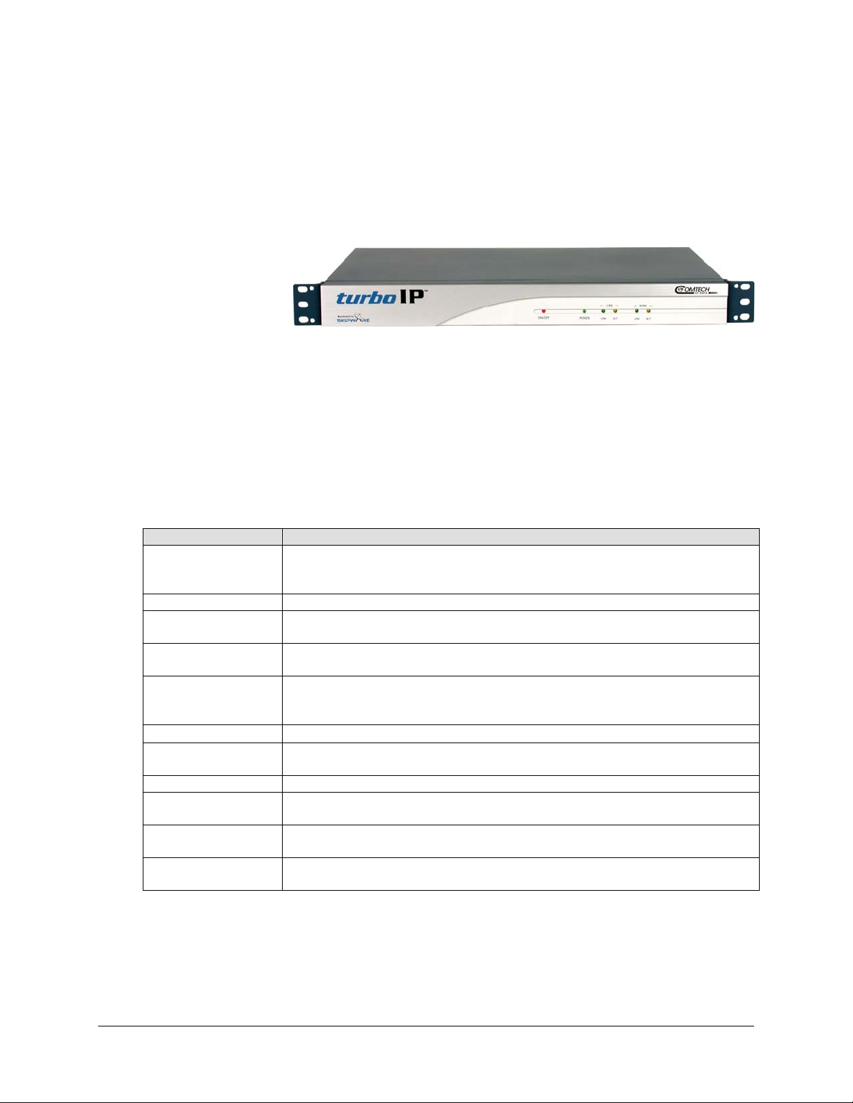
Figure 1-1. turboIP Front Panel View
Front Panel Control/LEDs
ON/OFF Recessed power reset switch
POWER Green when power is applied
LAN/LINK Green when LAN Port senses 10/100 Base-T link
LAN/ACT Flashing amber when LAN Port sense s Ethernet Activity
WAN/LINK Green when WAN Port senses 10/100 Base-T link
WAN/ACT Flashing amber when WAN Port senses Ethernet Activity
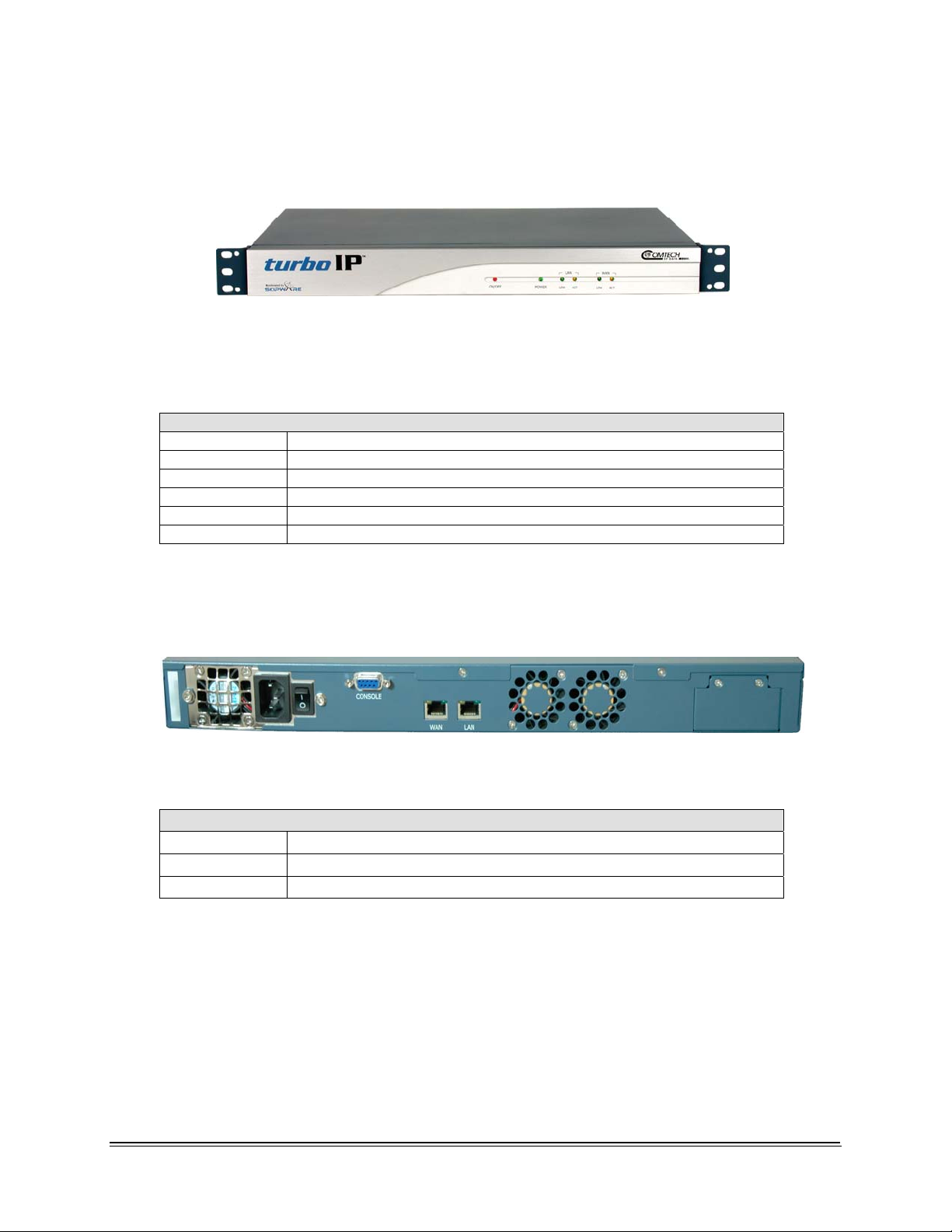
Figure 1-2. turboIP Rear Panel View
Rear Panel Connectors
CONSOLE EIA-232 Female 9-pin for serial console CLI
WAN RJ-45, 10 Base-T/100 Base-T Ethernet, Auto-Sensing
LAN RJ-45, 10 Base-T/100 Base-T Ethernet, Auto-Sensing
1-6
Page 19

turboIPv4.0 Revision 6
Overview MN/TURBOIP.IOM
Physical Specifications and Approvals
Temperature Operating: 5° to 45°C (41° to 113°F)
Storage: 0° to 75°C (32° to 138°F)
Humidity Operating: 5 to 95% @ 40°C (104°F), non-condensing
Vibration Operating: 5 to 17 Hz, 0.1” double amplitude displacement
17 to 500 Hz
1.5G acceleration peak-to-peak (maximum)
Shock Operating: 15G acceleration peak (1 ms duration)
Safety UL/CSA/TV/CE/FCC
EMI Meets FCC/VDE Class A
Power Supply 90~132 VAC or 180~260 VAC
@ 47~63 Hz, 150W maximum
Chassis
Dimensions
Weight
Heavy duty steel with aluminum front panel
19.0W x 1.75H x 18.4D inches
(48.3 x 4.45 x 46.7 cm)
12 lbs (5.44 kg)
Cooling Fans Qty. 2, 6.3 CFM sleeve cooling fans (rear)
1-7
Page 20

turboIPv4.0 Revision 6
Overview MN/TURBOIP.IOM
This page intentionally left blank.
1-8
Page 21

Chapter 2. Fail to Wire
2.1 DESCRIPTION
The Fail to Wire (FTW) function provides a low-cost solution for high network
availability. If the unit fails, then the installed FTW board allows traffic to bypass the
turboIP™ as if it were simply a wire. This means that a unit failure will not bring down
the whole network. Traffic will continue to pass and, at most, the existing TCP sessions
will be terminated and have to be restarted. The FTW functionality provides network
reliability without the added cost of one-for-one redundancy.
2.2 FAIL TO WIRE BOARD OPERATION
If the turboIP fails (excluding loss of power), then the FTW board switches into “wire”
mode approximately 7 to 10 seconds after the failure. At this time, all traffic is bypassed
around the turboIP. All active TCP sessions will timeout and need to be restarted. Newly
started TCP sessions will be bypassed around the turboIP without acceleration.
If turboIP reboots, then the FTW board switches to wire mode seven to 10 seconds after
the reboot is initiated, and stays in “wire” mode until the reboot is completed. Hence, 7 to
10 seconds is the extent of network outage caused by a reboot of the turboIP.
If the turboIP loses power, then the FTW board immediately switches into “wire” mode.
Approximately one second of traffic is lost during this switch. In addition, all TCP
sessions will timeout and have to be restarted.
While the turboIP is off, the FTW board is in “wire” mode and all traffic is bypassed
around the turboIP. When the turboIP is powered on again, the FTW board switches from
“wire” mode to “normal” mode during which time no traffic passes through the turboIP
for 7 to 10 seconds. After this period, the board will switch back into “wire” mode and
bypass traffic around the turboIP for 33 seconds while turboIP is booting. When the
turboIP finishes bootup, the FTW board switches from “wire” mode to “normal” mode
and the turboIP begins normal operations. About one second of traffic loss is possible
during this final switch.
2-1
Page 22
turboIPv4.0 Revision 6
Fail to Wire MN/TURBOIP.IOM
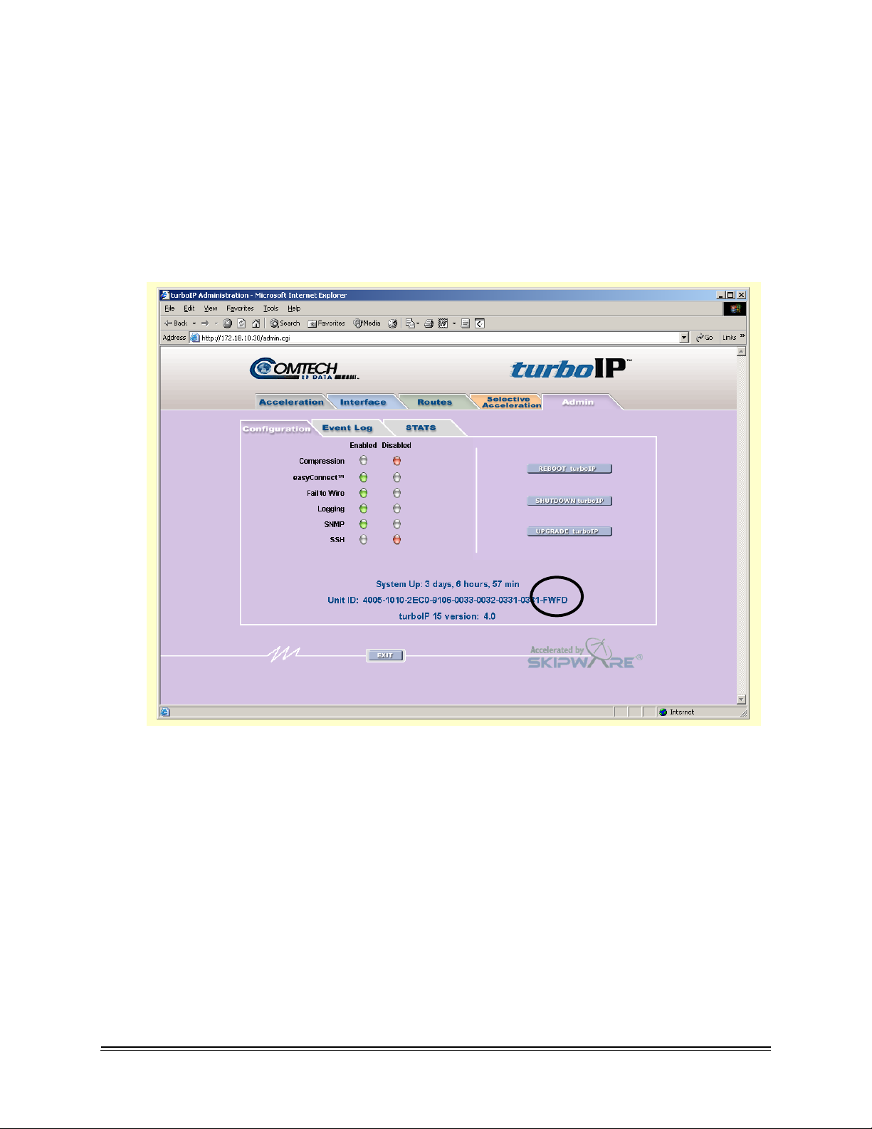
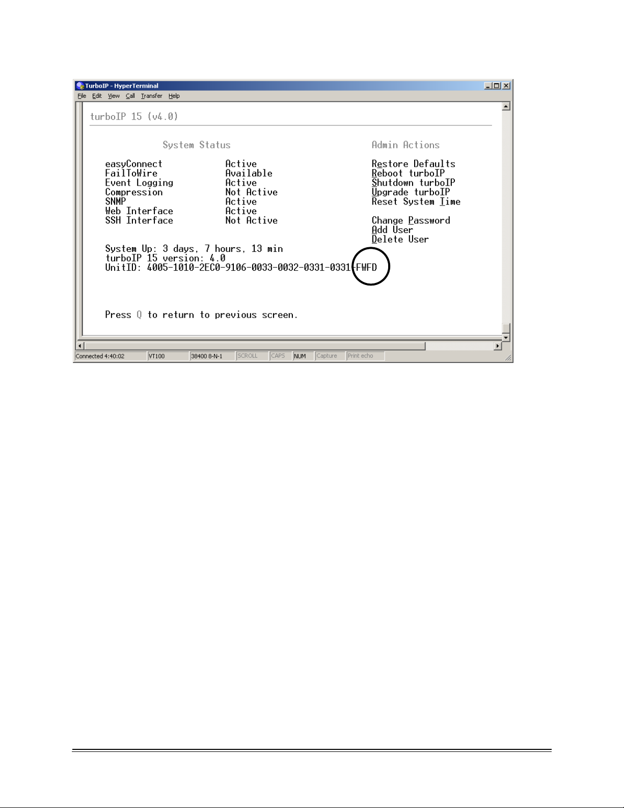
2.3 FAIL TO WIRE BOARD INSTALLED
If the Fail to Wire (FTW) board is installed in the turboIP, then the last four characters of
the Unit ID on the Upgrade page will read “FWFD”.
The presence of a FTW board can be verified by looking at the Unit ID on both the HTTP
interface and the CLI interface as shown below.
2-2
Page 23
turboIPv4.0 Revision 6
Fail to Wire MN/TURBOIP.IOM
2-3
Page 24
turboIPv4.0 Revision 6
Fail to Wire MN/TURBOIP.IOM
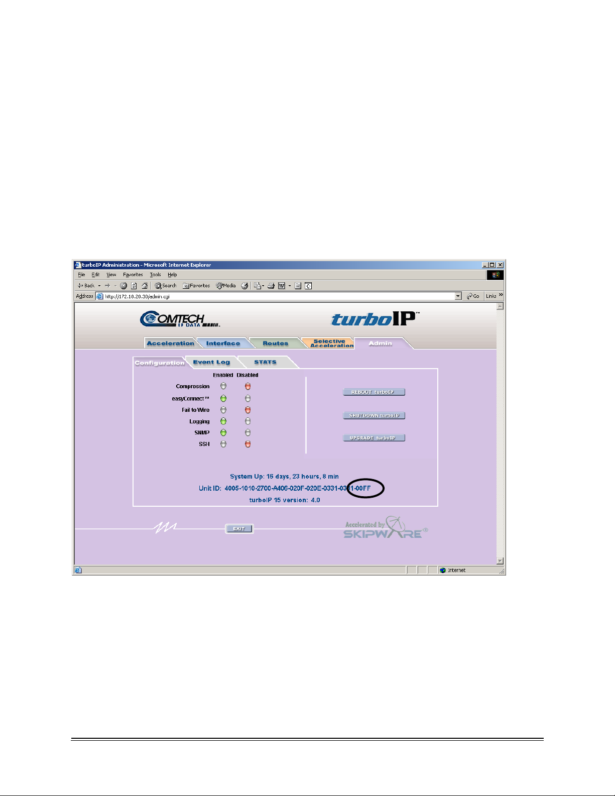
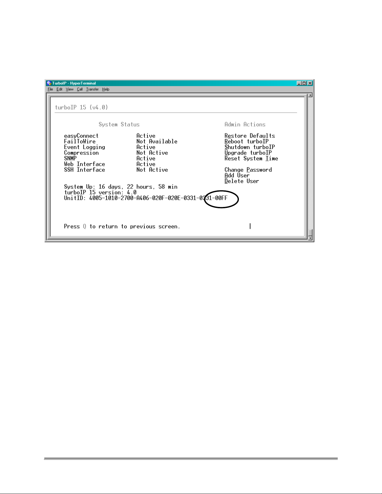
2.4 NO FAIL TO WIRE BOARD INSTALLED
If no FTW board is installed as part of the turboIP, then the last four characters of the
Unit ID on the Upgrade page will read “00FF”. Without a FTW board installed in the
turboIP this feature is unavailable. The unit will detect the absence of FTW capability
and not be able to switch into “wire” mode during possible failures or reboots.
The absence of a FTW board can be verified by looking at the Unit ID on the HTTP
interface and the CLI interface as shown below.
2-4
Page 25
turboIPv4.0 Revision 6
Fail to Wire MN/TURBOIP.IOM
2-5
Page 26

turboIPv4.0 Revision 6
Fail to Wire MN/TURBOIP.IOM
This page intentionally left blank.
2-6
Page 27

Chapter 3. easyConnect™
easyConnect™ is Comtech EF Data’s intelligent networking technology intended to
allow easy integration of turboIP™ into existing networks. It also simplifies design and
installation of a new network. It reduces network reconfiguration that is required when
introducing turboIP into an existing link. easyConnect™ can be turned ON after
turboIP V3.0 or later.
3.1 easyConnect™ ON
With easyConnect™ enabled, turboIP™ can be added to existing links without impacting
existing non-TCP traffic and without having to reconfigure existing network devices. It
also reduces the complexity when designing and installing a new network.
easyConnect™ mode:
All IP and Non-IP traffic is transparently bridged.
IP multicast is transparently bridged
Unicast IP datagrams that do not contain TCP payload are transparently bridged,
and can be assigned a Priority or bandwidth restriction with Selective
Acceleration Rules.
Unicast IP datagrams that contain TCP payload can be assigned a Priority or
bandwidth restriction with Selective Acceleration Rules. Also, Selective
Acceleration can be used to designate which TCP traffic is accelerated and which
is not accelerated.
With easyConnect™ mode, the unit has only one IP address (Management IP Address)
that both the LAN and WAN port will respond to.
3-1
Page 28

turboIPv4.0 Revision 6
easyConnect MN/TURBOIP.IOM
3.2 Important easyConnect Notes
1. With easyConnect™ mode, the turboIP™ cannot be the default gateway or the
next hop for any locally attached devices. Instead, the turboIP will work as a
IMPORTANT
transparent bridge.
2. For any turboIP
Route Table for TCP traffic to be forwarded through the turboIP. With V4.0,
Route entries are only needed to allow Web access or FTP upgrades of the
turboIP from an outside network
with SW earlier then V4.0, entries must be made into the
3-2
Page 29

Chapter 4. Configuring turboIP™
4.1 IMPORTANT CONFIGURATION NOTES
1. turboIP™ must be placed in the link such that it has visibility of TCP
traffic in both directions, i.e., the forward traffic as well as the TCP
CAUTION
acknowledgments must go through the unit. If the unit is placed such that it
only has visibility of forward traffic or TCP acknowledgments, all such
TCP sessions through turboIP™ will not be accelerated.
2. During configuration of turboIP™, a reboot is required for the three
following changes; all other changes are immediately in effect:
a. Initial Configuration Wizard
b. Restore to Factory Defaults
c. Upgrading of the Unit
4.2 REQUIRED EQUIPMENT LIST
In addition to the Ethernet cables and Ethernet switches/hubs required to connect
turboIP™ to the network, the following equipment is required for the console connection:
1. DB-9 (female) to DB-9 (male) straight-through modem cable
2. PC running terminal emulation program (such as HyperTerminal)
4–1
Page 30

turboIPv4.0 Revision 6
Configuring turboIP MN/TURBOIP.IOM
4.3 USER INTERFACES
turboIP™ supports a basic menu-driven interface, which is accessible using the console
port, or a web-based graphical user interface (GUI). The interfaces contain the same
functionality, with one exception. The USERID and PASSWORD are only configurable
via the console connection, for obvious security reasons.
CONSOLE SETTINGS
IMPORTANT
Baud Rate
Data Bits
Parity
Stop Bits
Hardware Flow Control
Software Flow Control
Terminal Emulation
Cable Configuration
38,400 bps
8
None
1
None
None
VT100/VT100J
Straight - Through
1. Entry of the numeric pad’s arrow keys when the NumLock is OFF
will work under Hyperterminal, provided that the client is running
Windows 2000, Service Pack 4. Microsoft has acknowledged a
bug for Hyperterminal shipped with Windows 2000 prior to Service
Pack 2 where the arrow keys were non-functional.
(
http://support.microsoft.com/default.aspx?kbid=263077).
2. Web-based graphical user interface (GUI) CAN ONLY be turned on
in CLI. End-user is required to run Configuration Wizard for initial
setup or log into CLI Menu to ENABLE “Web User Interface.’
4–2
Page 31

turboIPv4.0 Revision 6
Configuring turboIP MN/TURBOIP.IOM
4.4 CONFIGURATION WIZARD
turboIPV4.0 has implemented Configuration Wizard to be a user-friendly Command-Line
Interface(CLI) through serial console. Initial setup of the turboIP must be done using the
serial console. A series of step-by-step instructions will guide you through the initial
configuration. End user is required to run the Configuration Wizard with the following
conditions:
Brand new turboIP units shipped with Factory Defaults.
After Restoring Factory Defaults in the CLI Administration page.
Changes with turboIP V4.0 Configuration Wizard
IMPORTANT
1. Initial configuration via the Configuration Wizard is no longer
required before the turboIP can be used. Acceleration will be
enabled at all times. If the user wants to change any of the default
settings or access any user interfaces, the Configuration Wizard
must be run.
2. The box will be pre-configured to 15 Mbps for the WAN
Transmission Rate. Congestion Control will be set to
“Per-Connection.”
3. No user interfaces will be accessible until the Configuration Wizard
is run.
4. The Wizard will ask the user if they will be configuring the box via
the network. If the user selects that they will not be configuring the
box for the network, the Wizard will not ask any network specific
questions such as IP Address, Subnet Mask, Default Gateway, Web
configuration and SNMP configuration. If the user selects to
configure the box via the network, the network specific questions
will still appear in the wizard.
5. All network configuration will still be available via the user
interfaces after the wizard is run.
6. The Maximum Round Trip Time (RTT) setting is no longer
available.
4–3
Page 32

turboIPv4.0 Revision 6
Configuring turboIP MN/TURBOIP.IOM
4.4.1 END USER LICENSE AGREEMENT (EULA)
To use the console interface, launch a terminal window emulation program such as
HyperTerminal on Microsoft Windows, set the console settings. For a brand new
turboIP unit, the console will display EULA(End User License Agreement).
In order to access to the Configuration Wizard, end user is required to accept turboIP
License Agreement. After Accepting the License Agreement, user may proceed to
turboIP Configuration Wizard
.
4–4
Page 33

turboIPv4.0 Revision 6
Configuring turboIP MN/TURBOIP.IOM
4.4.2 CONFIGURATION WIZARD TURBOIP V4.0 - SUMMARY
Note: At any time during the initial Configuration Wizard, the ESC key can be used to
cancel all changes and reboot.
Information to be provided throughout the Configuration Wizard is listed in the
following table. Detailed information is contained in the Section Listed.
Section Configuring
Item
4.4.2.1 Username
Password
4.4.2.2
N/A
Re-enter
password
UTC Month
UTC Day
UTC Year 4 digit integer ‘2006’
Default
Value
N/A Must be at least 5 and no
N/A ‘C0mtech!’
N/A
Current
system
setting
Format Example
‘admin’
more than 31 alphanumeric
characters in length.
Passwords must be at least
8 characters and no more
than 31 characters in length.
Passwords are case
sensitive and must contain
at least one character from
each of the following groups:
uppercase, lowercase, digit,
and special character.
Special characters include
“_!.;:<>,[]{}\|()*&^%$#@`~'+=?/”
Two digit integer between 1
to 12
Two digit integer between 1
to 30 or 31
‘C0mtech!’
‘01’
‘01’
4.4.2.3
UTC Military
Time
Management
IP Address
Management
Subnet Mask
Default
Gateway
hh:mm:ss ‘09:19:51’
10.10.10.1 ddd.ddd.ddd.ddd ‘192.9.1.3’
255.255.255.0 ddd.ddd.ddd.ddd ‘255.255.255.0’
0.0.0.0 ddd.ddd.ddd.ddd
Must be on same subnet as
Management IP.
4–5
‘192.9.1.4’
Page 34

turboIPv4.0 Revision 6
Configuring turboIP MN/TURBOIP.IOM
4.4.2.4 WAN Rate
4.4.2.5
4.4.2.6 Web Interface
4.4.2.7
DoD Warning
Banner
Configure
SNMP
15 Mbps A number, followed by a
space and 'bps', 'kbps' or
'Mbps'
Must be ≥ 10 kbps and ≤ 15
Mbps
N/A 1 for Enable
2 for Disable
Selecting ‘Yes’ will enable
the Department of Defense
warning banner on the
Serial and SSH interfaces,
which will remain on the
screen until the user hits a
key on their keyboard.
Note: The DoD Warning
Banner can only be enabled
or disabled via the
Configuration Wizard.
N/A 1 for Enable
2 for Disable
N/A 1 for Enable
2 for Disable
‘1000 kbps’
Save Changes & Reboot
Save Changes & Shutdown
15
Finishing
Configuration
Cancel All Changes &
Reboot
Cancel All Changes &
Shutdown
4–6
Page 35

turboIPv4.0 Revision 6
Configuring turboIP MN/TURBOIP.IOM
4.4.2.1 CONFIGURATION WIZARD TURBOIP V4.0 - USER ACCOUNTS
User Accounts - There shall be two levels of user accounts: Administrator and Normal
User. There must always be at least one Administrator account.
The first Administrator account must be created through the Configuration Wizard. If
only one Administrator account exists, the user will not be able to delete the account. An
error message will be displayed if there is an attempt to delete the Administrator.
Usernames - must be at least 5 and no more than 31 alphanumeric characters in length.
4–7
Page 36

turboIPv4.0 Revision 6
Configuring turboIP MN/TURBOIP.IOM
4.4.2.2 CONFIGURATION WIZARD TURBOIP V4.0 – PASSWORD
Password Complexity - Passwords must be at least 8 characters and no more than 31
characters in length.
Passwords are case sensitive and must contain at least one character from each of the
following groups: uppercase, lowercase, digit, and special character. Special characters
include “_!-.;:<>,[]{}\|()*&^%$#@`~'+=?/”
When changing passwords, at least four characters in the new password must be different
from the old password. The system will not keep any record of old passwords once a
password is changed.
4–8
Page 37

turboIPv4.0 Revision 6
Configuring turboIP MN/TURBOIP.IOM
If the Administrator login or password is lost, the turboIP can be
restored to Factory Defaults using the following account only
IMPORTANT
accessible via the serial interface:
username: safe
password: C0mtech!
Once the factory defaults are restored, the turboIP can be rebooted and
the user will be able to accept the EULA and begin the Configuration
Wizard.
4.4.2.3 CONFIGURATION WIZARD TURBOIP V4.0 – NETWORK SETTINGS
REMOTE ACCESS
FOR
Network Settings – To allow access to the turboIP via the network (using the Web or
SNMP IP interface) select ‘Yes’.
Management IP Address/Subnet Mask – Enter the IP you wish to assign to the turboIP
(both the LAN and WAN port will respond to this IP).
Default Gateway - Enter the IP of the Gateway (must be on same subnet as
Management IP).
4–9
Page 38

turboIPv4.0 Revision 6
Configuring turboIP MN/TURBOIP.IOM
4.4.2.4 CONFIGURATION WIZARD TURBOIP V4.0 – WAN TRANSMISSION
RATE
WAN Transmission Rate – Set the maximum bandwidth available for TCP traffic on
the WAN interface (a number, followed by a space and 'bps', 'kbps' or 'Mbps'). Must be
≥ 10 kbps and ≤ 15 Mbps. Setting WAN transmission rate in excess of available
bandwidth could lead to a packet loss and degraded performance. If you have a mix of
TCP and non-TCP traffic, use this setting to limit the bandwidth for TCP traffic.
Example 1 – If a pair of turboIPs’ were used to accelerate TCP traffic on a satellite link
where satellite modem A has a TX data rate of 12 Mbps and satellite modem B has a TX
data rate of 2048 kbps, the WAN setting for turboIP A would be 12 Mbps and would be
2048 kbps for turboIP B.
Example 2 – If a turboIP was in place at a hub where there were three outbound satellite
links to three separate remotes with the following links;
Link A – Hub 4 Mbps Outbound, Remote A 1536 kbps Inbound
Link B – Hub 3 Mbps Outbound, Remote B 1024 kbps Inbound
Link A – Hub 2 Mbps Outbound, Remote C 768 kbps Inbound
The Hub turboIP WAN would be set to 9 Mbps to equal the total available Outbound
bandwidth (4 + 3 + 2). In this example, Selective Acceleration Rules would need to be
created to limit the bandwidth to match the Outbound TX data rate for each Remote. The
Remote TurboIP WAN setting would be set to the Inbound TX data rate to the Hub.
4–10
Page 39

turboIPv4.0 Revision 6
Configuring turboIP MN/TURBOIP.IOM
4.4.2.5 CONFIGURATION WIZARD TURBOIP V4.0 – DOD BANNER
DoD Warning Banner – Selecting ‘Yes’ will enable the Department of Defense warning banner
on the Serial and SSH interfaces, which will remain on the screen until the user hits a key on their
keyboard.
Note - The DoD Warning Banner can only be enabled or disabled via the Configuration Wizard.
4–11
Page 40

turboIPv4.0 Revision 6
Configuring turboIP MN/TURBOIP.IOM
4.4.2.6 CONFIGURATION WIZARD TURBOIP V4.0 – WEB INTERFACE
Web Interface – Selecting ‘Yes’ will enable the turboIP Web interface, for local or remote
access.
4–12
Page 41

turboIPv4.0 Revision 6
Configuring turboIP MN/TURBOIP.IOM
4.4.2.7 CONFIGURATION WIZARD TURBOIP V4.0 – SNMP
SNMP can be configured via the Configuration Wizard or later via the CLI. If
Configuring SNMP is selected during the turboIP Configuration Wizard setup step, the
following tables provide the steps for SNMP Configuration.
4–13
Page 42

turboIPv4.0 Revision 6
Configuring turboIP MN/TURBOIP.IOM
If SNMP v2 is selected, see the following table.
Step Configuring Item for
SNMP v2
1 SNMP sysName N/A ‘Comtech’
2 SNMP sysLocation N/A ‘Tempe, Arizona’
3 SNMP sysContact N/A ‘TechSupport’
4 Trap Destination Ip
Address
5 Read Community N/A Between 1-255
6 Set Community N/A Between 1-255
7 Trap Community N/A Between 1-255
8 enable SNMP N/A 1 for Enable
9 Save SNMP Changes N/A 1 for save changes
10 Return to Configuration
Wizard
Default
Value
N/A ddd.ddd.ddd.ddd ‘192.1.1.1’
N/A
Format Example
‘public’
characters
‘private’
characters
‘trap’
characters
2 for Disable
2 for Cancel changes
4–14
Page 43

turboIPv4.0 Revision 6
Configuring turboIP MN/TURBOIP.IOM
If SNMP v3 is selected, see the following table.
Step Configuring Item for
SNMP v3
1 SNMP sysName N/A ‘Comtech’
2 SNMP sysLocation N/A ‘Tempe,
3 SNMP sysContact N/A ‘TechSupport’
4 Trap Destination IP
Address
5 Username ‘snmpadmin’
6 Enable Authentication 1 for Yes
6-1 Auth. Passphrase Enter Authentication
7 Enable Privacy 1 for Yes
Default
Value
N/A ddd.ddd.ddd.ddd ‘192.1.1.1’
Format Example
Arizona’
2 for No
‘comtechauth’
Passphrase if
Authentication is
selected.
Between 8-255
characters.
2 for No
7-1 Priv. Passphrase Enter Privacy
Passphrase if Privacy is
selected.
Enter between 8 and
255 characters.
8 enable SNMP N/A 1 for Enable
2 for Disable
9 Save SNMP Changes N/A 1 for save changes
2 for Cancel changes
10 Return to Configuration
Wizard
N/A
‘comtechprivacy’
4–15
Page 44

turboIPv4.0 Revision 6
Configuring turboIP MN/TURBOIP.IOM
4.5 MENUS AND FUNCTIONS - SUMMARY
The menus and functions that comprise this section are:
CLI Menu
Menu Description
Configure Interfaces
Menu
Gateway Menu
Routing Menu Add, adjust, or delete routes from system routing table
SNMP Menu Set SNMP subsystem On/Off
Selective Acceleration
Menu
Enter Management IP Address and subnet mask
Turn WEB Interface On/Off
Turn SSH Interface On/Off
Set LAN/WAN port Link Setting
Display LAN/WAN MAC address and Link Status
Set LAN and WAN Transmission Rates
Set WAN Maximum Transfer Unit (MTU)
Turn Compression On/Off
Set Congestion Control to Per-Connection or Rate Pacing
Route entries are only required for remote network access to
the turboIP.
Set SNMP system variables such as, System Information,
Community Strings, and Trap Destination.
Add, move, edit, and delete TCP/UDP QoS/Acceleration rules
Monitor statistics by priority
Each rule has the following variables - Source IP
address/Mask, Destination IP address/Mask, Protocol, Source
Port, Destination Port, Priority, Bandwidth, Acceleration
ON/OFF, and Status.
Administration Menu Displays System Status for turboIP features – easyConnect,
FailToWre, Event Logging, Compression, SNMP, Web
Interface, SSH Interface
Displays System Up Time, turboIP Version, Unit ID
Used to administer the system functions – Restore Defaults,
Reboot, Shutdown, Upgrade, Reset System Time, Change
Password, Add User, Delete User
Enable Logging, View or Clear Event Log
Display/Reset System Statistics – Avg. Compression Ratio,
Session Statistics, WAN and LAN Statistics
4–16
Page 45

turboIPv4.0 Revision 6
Configuring turboIP MN/TURBOIP.IOM
WEB Menu
Menu Description
Acceleration Set LAN and WAN Transmission Rates
Set WAN Maximum Transfer Unit (MTU)
Turn Compression On/Off
Set Congestion Control to Per-Connection or Rate Pacing
Interface Enter Management IP Address and subnet mask
Set LAN/WAN port Link Setting
Display LAN/WAN MAC address and Link Status
Routes Add, adjust, or delete routes from system routing table
Route entries are only required for remote network access to
the turboIP.
Selective Acceleration
Rules
Stats
Administration Menu
Configuration
Event Log
Stats
Add, move, edit, and delete TCP/UDP QoS/Acceleration rules
Monitor statistics by priority
Each rule has the following variables - Source IP
address/Mask, Destination IP address/Mask, Protocol, Source
Port, Destination Port, Priority, Bandwidth, Acceleration
ON/OFF, and Status.
Displays System Status for turboIP features – easyConnect,
FailToWire, Event Logging, Compression, SNMP, SSH
Interface
Displays System Up Time, turboIP Version, Unit ID
Used to administer the system functions – Reboot, Shutdown,
Upgrade
Enable Logging, View or Clear Event Log
Display/Reset System Statistics – Avg. Compression Ratio,
Session Statistics, WAN and LAN Statistics
Note: The Web interface Administration menu does not
support the following functions - Restore Defaults, Changes to
User Accounts or Password, and Reset System Time. These
functions are restricted to the CLI or SSH serial interface.
4–17
Page 46
turboIPv4.0 Revision 6
Configuring turboIP MN/TURBOIP.IOM
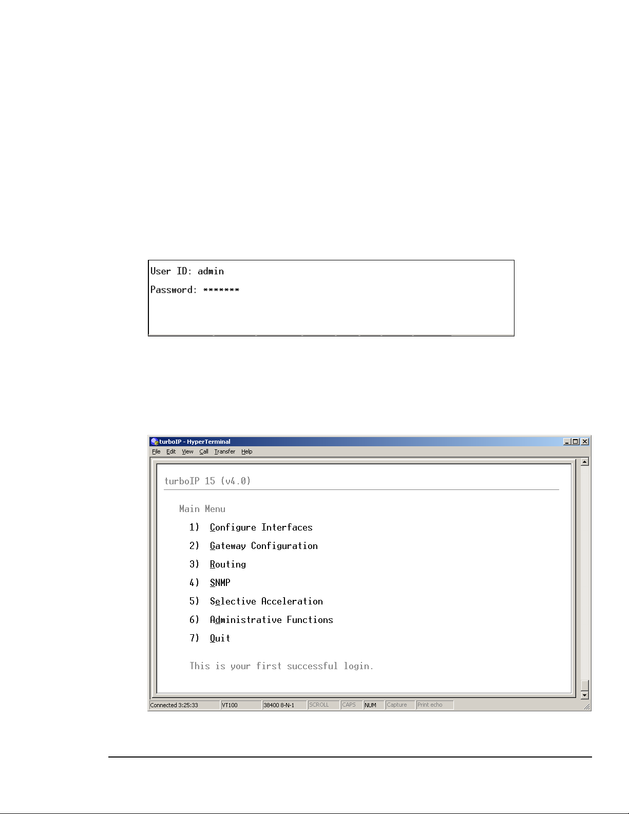
4.5.1 CLI - LOG IN
To use the console interface, launch a terminal window emulation program such as
HyperTerminal on Microsoft Windows, set the console settings. For a brand new
turboIP unit, the console will display EULA(End User License Agreement) and running
thorough Configuration Wizard is required.
Login using the username and password.
For Example:
A successful log in from the CLI will open the Main Menu. Note that the first successful
login is displayed also. With all subsequent logins, the time and date of the last successful
login will be displayed.
4–18
Page 47

turboIPv4.0 Revision 6
Configuring turboIP MN/TURBOIP.IOM
4.5.2 CLI - C
ONFIGURE INTERFACE MENU
Function Select Description
easyConnect N/A Status Only (On)
Management IP M Management IP address
Management Subnet Mask
Web Interface E Select - On/Off
SSH Interface S Select - On/Off
LAN Link Setting L Select - Auto-Negotiate, 10baseT, 10baseT-FD,
100baseTx, 100baseTx-FD
MAC Address (Read only)
Link Status – Established, Not Established
Media Type (If Established)
Auto-Negotiation - (If in Auto-Negotiate and Established)
WAN Link Setting W Select - Auto-Negotiate, 10baseT, 10baseT-FD,
100baseTx, 100baseTx-FD
MAC Address (Read only)
Link Status – Established, Not Established
Media Type (If Established)
Auto-Negotiation - (If in Auto-Negotiate and Established)
4–19
Page 48

turboIPv4.0 Revision 6
Configuring turboIP MN/TURBOIP.IOM
4.5.3 CLI - GATEWAY CONFIGURATION MENU
Function Select Description
LAN L LAN Transmission Rate – 10Mbps/100Mbps
WAN
Compression C Select - On/Off
Congestion Control O Select – Per-Connection or Rate Pacing
W WAN Transmission Rate – (a number, followed by a space and
'bps', 'kbps' or 'Mbps'). Must be ≥ 10 kbps and ≤ 15 Mbps
M Maximum Transfer Unit (MTU): MTU size in bytes, default 1500
4.5.3.1 WAN TRANSMISSION RATE
Set the maximum bandwidth available for TCP traffic on the WAN interface (a
number, followed by a space and 'bps', 'kbps' or 'Mbps'). Must be ≥ 10 kbps and
≤ 15 Mbps. Setting WAN transmission rate in excess of available bandwidth could
lead to a packet loss and degraded performance.
If you have a mix of TCP and non-TCP traffic, use this setting to limit the
bandwidth for TCP traffic.
4–20
Page 49

turboIPv4.0 Revision 6
Configuring turboIP MN/TURBOIP.IOM
Example 1 – If a pair of turboIPs’ were used to accelerate TCP traffic on a satellite
link where satellite modem A has a TX data rate of 12 Mbps and satellite modem B
has a TX data rate of 2048 kbps, the WAN setting for turboIP A would be 12 Mbps
and would be 2048 kbps for turboIP B.
Example 2 – If a turboIP was in place at a hub where there were three outbound
satellite links to three separate remotes with the following links;
Link A – Hub 4 Mbps Outbound, Remote A 1536 kbps Inbound
Link B – Hub 3 Mbps Outbound, Remote B 1024 kbps Inbound
Link A – Hub 2 Mbps Outbound, Remote C 768 kbps Inbound
The Hub turboIP WAN would be set to 9 Mbps to equal the total available
Outbound bandwidth (4 + 3 + 2). In this example, Selective Acceleration Rules
would need to be created to limit the bandwidth to match the Outbound TX data rate
for each Remote. The Remote TurboIP WAN setting would be set to the Inbound
TX data rate to the Hub.
4.5.3.2 MAXIMUM TRANSFER UNIT (MTU)
This setting enables the turboIP to better support interoperability with other IP
devices requiring less than 1500-byte TCP payloads. Default setting for the MTU is
1500 bytes.
4.5.3.3 COMPRESSION
With Compression enabled, the turboIP will compress accelerated TCP Data,
Compression is not applied to non-TCP or non accelerated TCP.
4.5.3.4 CONGESTION CONTROL
Per-Connection Mode – Should be used to support dynamic bandwidth paths, where
the bandwidth may be different for any of the paths being accelerated by the turboIP.
Rate Pacing Mode– Should be when bandwidth path for accelerated TCP traffic
remains constant with the set WAN Transmission Rate. In Rate Pacing Mode, the
turboIP meters out bursty traffic at a rate not to exceed the configured transmission
rate of the satellite channel. This prevents the satellite channel from becoming
congested and will maximize accelerated TCP throughput to match the set WAN
Transmission Rate.
4–21
Page 50

turboIPv4.0 Revision 6
Configuring turboIP MN/TURBOIP.IOM
4.5.4 CLI - ROUTE CONFIGURATION MENU
Function Select Description
Add Route A Enter - Route Number, Destination IP Address, Netmask, Next
Hop IP Address
Route Status – set to Active or Not in Service
Note – Status will display as Invalid if turboIP was not able to
create the Route. For example, if the Next Hop was not on the
same subnet as the turboIP.
Remove Route R Select Route Number to remove
Edit Route E Select Route Number to edit
Route entries are not required for the turboIP V4.0 to accelerate or
forward any IP traffic. SW versions prior to 4.0 do require Route entries
IMPORTANT
to forward any TCP traffic.
Route entries are only needed to allow access to the turboIP from an
outside network (using the Web or SNMP IP interface).
4–22
Page 51

turboIPv4.0 Revision 6
Configuring turboIP MN/TURBOIP.IOM
4.5.5 CLI - SNMP CONFIGURATION MENU
SNMP V2 CLI MENU DISPLAY
SNMPV2 CONFIGURATION
Function Select Description
SNMP S Select - On/Off
System Information
Name
Location
Contact
Community Names
Read-Write Access
Read-Only Access
Notification Access
Trap Destination IP
Address
N
L As required
C As required
W
O SNMP GET Community String
A SNMP Trap Community String
T IP address destination for traps
As required
SNMP SET Community String
Run SNMP
Configuration Wizard
R Select to erase all SNMP settings or to change to a different
SNMP Version (2 or 3)
See Section 4.4.2.7 Configuration Wizard - SNMP
4–23
Page 52

turboIPv4.0 Revision 6
Configuring turboIP MN/TURBOIP.IOM
SNMP V3 CLI MENU DISPLAY
When SNMP V3 is selected, no SNMP V3 settings are displayed.
SNMPV3 C
ONFIGURATION
Function Select Description
SNMP S Select - On/Off
Run SNMP
Configuration Wizard
R Select to erase all SNMP settings or to change to a different
SNMP Version (2 or 3)
See Section 4.4.2.7 Configuration Wizard - SNMP
4–24
Page 53

turboIPv4.0 Revision 6
Configuring turboIP MN/TURBOIP.IOM
4.5.6 CLI - SELECTIVE ACCELERATION MENU
Function Select Description
View/Edit Rules 1 or V Select to view, edit add or remove Selection Acceleration Rule
Statistics 2 or S Select to view Selection Acceleration Statistics by Priority
4–25
Page 54

turboIPv4.0 Revision 6
Configuring turboIP MN/TURBOIP.IOM
SELECTIVE ACCELERATION VIEW/EDIT RULES MENU
Function Select Description
Insert Rule I Insert the rule before selected rule.
Move Rule M Move the selected rule to higher or lower order of rule ID.
Edit Rule E Modify the selected rule to change its variables.
Remove Rule R Remove one selected rule at a time.
First F Go to the first page where the rule ID at #
Last L Go to the last page of the rule table at #
Scroll Up U Scroll up one page at a time.
Scroll Down D Scroll down one page at a time.
Selective Acceleration Rules can be applied to any IP traffic through
the turboIP; assigning a Priority (1-8) and Bandwidth limit to IP
IMPORTANT
traffic that falls within the Rule.
For any traffic that meets the criteria of more than one Rule, the first
(lowest #) Rule will be applied.
The Default Rule is applied to all traffic not meeting a defined Rule
and cannot be edited or removed.
4–26
Page 55

turboIPv4.0 Revision 6
Configuring turboIP MN/TURBOIP.IOM
SELECTIVE ACCELERATION INSERT/EDIT RULES MENU
Function Select Description
Source Address
1 or S Default 0.0.0.0 (wild card – applied to any IP address)
Mask
Source Address
2 or D Default 0.0.0.0 (wild card – applied to any IP address)
Mask
Priority 3 or P Select 1 – 8 (1 being highest priority)
Protocol 4 or R Select TCP, UDP or Any
Source Port
Start
End
Destination Port
Start
End
Maximum
5 Default __ (no entry = wild card – applied to any port)
Enter Start and End Port numbers for a range of ports.
Enter same port for Start and End for a single port.
6 Default __ (no entry = wild card – applied to any port)
Enter Start and End Port numbers for a range of ports.
Enter same port for Start and End for a single port.
7 or M Default 15000 kbps
Bandwidth
Acceleration 8 or A Select On to accelerate TCP traffic within this Rule.
Select Off to bypass acceleration for TCP traffic within this Rule.
Status 9 or T Select Active for Rule to be applied.
Select Not in Service to have Rule not applied.
4–27
Page 56

turboIPv4.0 Revision 6
Configuring turboIP MN/TURBOIP.IOM
SELECTIVE ACCELERATION STATISTICS MENU
Selective Acceleration Statistics are sorted by Priority (not by Rule #). The Priority 8
Statistics include any Default Rule traffic plus any traffic within a Rule with a Priority
of 8.
All Statistics (except Current Rate and Accelerated Sessions) are cumulative from the last
instance of clearing Statistics.
Statistic Description
Packets Sent Packets sent for this Priority
Packets Dropped Packets Dropped for this Priority
Cur Rate (kbps) Current Rate in kbps for this Priority
Avg Rate (kbps) Avg Rate in kbps for this Priority
Max Rate (kbps) Max Rate in kbps for this Priority
Accel Sessions Current Accelerated Sessions for this Priority
4–28
Page 57

turboIPv4.0 Revision 6
Configuring turboIP MN/TURBOIP.IOM
4.5.7 CLI - ADMINISTRATIVE FUNCTIONS MENU
Function Select Description
Configuration/
Actions
Event Log 2 or E Select to view or clear Event Log
Statistics 3 or S Select to view or clear statistics
1 or C Select to perform administrative functions
4–29
Page 58

turboIPv4.0 Revision 6
Configuring turboIP MN/TURBOIP.IOM
ADMINISTRATIVE CONFIGURATIONS/ACTIONS MENU
SYSTEM STATUS (READ ONLY)
turboIP Function Description
easyConnect Active (always enabled)
FailToWire Available/Not Available – indicates presence of Fail to Wire
Hardware
Event Logging Active/Inactive
Compression Active/Inactive
SNMP Active/Inactive
Web Interface Active/Inactive
SSH Interface Active/Inactive
System Up Displays System Up Time in days/hours/minutes
TurboIP version Current SW Version
Unit ID Unit ID #
4–30
Page 59

turboIPv4.0 Revision 6
Configuring turboIP MN/TURBOIP.IOM
ADMIN ACTIONS
Function Select Description
Restore Defaults E Restore Factory Default settings (SSH/CLI Only function)
Reboot turboIP R Manual Reboot
Shutdown turboIP S Manual Shutdown
Upgrade turboIP U Upgrade turboIP SW – See Section
Reset System Time T Time reset (SSH/CLI Only function)
Change Password P Change current Password (SSH/CLI Only function)
Add User A Add new User account (SSH/CLI Only function)
Delete User D Delete User account (SSH/CLI Only function)
Multiple Users – Up to five user accounts are supported via the Web, SSH and Serial
interfaces. Account authentication will be done using passwords. Passwords shall be
required to follow the complexity requirements specified in the Password Complexity
section below.
User Accounts - There shall be two levels of user accounts: Administrator and Normal
User. There must always be at least one Administrator account.
The first Administrator account must be created through the Configuration Wizard. If
only one Administrator account exists, the user will not be able to delete the account. An
error message will be displayed if there is an attempt to delete the Administrator.
Usernames - must be at least five and no more than thirty-one alphanumeric characters
in length.
Administrator Functions - The Administrator shall be able to change passwords, add
and delete users only through the SSH and Serial interfaces. Normal users will not be
able to see or edit these settings.
When adding user accounts, the Administrator must specify if the account is an
Administrator or Normal User.
The option to change usernames through the Serial interface will no longer be available.
To accomplish this, the Administrator can delete the user account and then add it back in
with a new username. If the Administrator user tries to add more than the maximum
number of user accounts, an error message will be displayed.
4–31
Page 60

turboIPv4.0 Revision 6
Configuring turboIP MN/TURBOIP.IOM
Password Complexity - Passwords must be at least 8 characters and no more than 31
characters in length.
Passwords are case sensitive and must contain at least one character from each of the
following groups: uppercase, lowercase, digit, and special character. Special characters
include “_!-.;:<>,[]{}\|()*&^%$#@`~'+=?/”
When changing passwords, at least four characters in the new password must be different
from the old password. The system will not keep any record of old passwords once a
password is changed.
If the Administrator login or password is lost, the turboIP can be
restored to Factory Defaults using the following account only
IMPORTANT
accessible via the serial interface:
username: safe
password: C0mtech!
Once the factory defaults are restored, the turboIP can be rebooted and
the user will be able to accept the EULA and begin the Configuration
Wizard.
4–32
Page 61

turboIPv4.0 Revision 6
Configuring turboIP MN/TURBOIP.IOM
ADMINISTRATIVE EVENT LOG CONFIGURATION MENU
Function Select Description
Event Logging L Select On/Off
View log V Select to view log
Clear log C Select to clear log
4–33
Page 62

turboIPv4.0 Revision 6
Configuring turboIP MN/TURBOIP.IOM
ADMINISTRATIVE VIEW EVENT LOG
ADMINISTRATIVE STATISTICS MENU
4–34
Page 63

turboIPv4.0 Revision 6
Configuring turboIP MN/TURBOIP.IOM
Counter Name Description
Avg. Compression Ratio Average compression ratio over time (Initial value is 1.00).
Max. Accel. Session: Maximum number of accelerated TCP sessions currently
acting.
Max. Accel. Session Init/Sec Maximum number of accelerated TCP sessions that are
initiated per second.
Max. Accel. Session
Terminated/Sec
Session Requested
Failed
Sessions TimeOut Cumulated timeout sessions.
Bad Checksums Bad checksum packet counts
WAN TX Indicates data transmitted to the WAN: packets, bytes, and
WAN RX Indicates data received from the WAN: packets, bytes, and
LAN TX Indicates data transmitted to the LAN: packets, bytes, and
LAN RX Indicates data received from the LAN: packets, bytes, and
Maximum number of accelerated TCP sessions that are
terminated per second.
Cumulated number that session requests failed.
drop.
drop.
drop.
drop.
Function/Admin
Action
Reset Compression
Ratio
Description Operation
Reset compression ratio counter back
to 1.0.
Press “C” on CLI or click
“Reset Compression Ratio”
button on web.
Reset ALL Reset counters in the STATS page -
also includes the STATS in the
selective Acceleration menu.
4–35
Press “A
“Reset ALL” button
” on CLI or click
Page 64

turboIPv4.0 Revision 6
Configuring turboIP MN/TURBOIP.IOM
4.5.8 WEB – LOG IN
To use the web interface, first configure the turboIP IP address and enable WEB
Interface through the console, then launch any standard web browser program such as
Internet Explorer on Microsoft Windows, and login using the configured username
and password.
Successful Log In will open the Web Acceleration Page
4–36
Page 65

turboIPv4.0 Revision 6
Configuring turboIP MN/TURBOIP.IOM
4.5.9 WEB – ACCELERATION PAGE
See Section 4.5.3 CLI – Gateway Configuration Menu for all details regarding configuring the
Acceleration settings.
On the web pages, values are enforced once SSAAVVEE is clicked.
IMPORTANT
4–37
Page 66

turboIPv4.0 Revision 6
Configuring turboIP MN/TURBOIP.IOM
4.5.10 WEB – INTERFACE PAGE
See Section 4.5.2 CLI – Configure Interface Menu for all details regarding configuring the
Interface settings.
On the web pages, values are enforced once SSAAVVEE is clicked.
IMPORTANT
4–38
Page 67

turboIPv4.0 Revision 6
Configuring turboIP MN/TURBOIP.IOM
4.5.11 WEB – ROUTES PAGE
See Section 4.5.4 CLI – Route Configuration Menu for all details regarding configuring the
Route settings.
On the web pages, values are enforced once SSAAVVEE is clicked.
IMPORTANT
4–39
Page 68

turboIPv4.0 Revision 6
Configuring turboIP MN/TURBOIP.IOM
4.5.12 WEB – SELECTIVE ACCELERATION PAGE
SELECTIVE ACCELERATION VIEW/EDIT RULES PAGE
See Section 4.5.6 CLI – Selective Acceleration Menu for all details regarding configuring the
Selective Acceleration settings.
On the web pages, values are enforced once SSAAVVEE is clicked.
IMPORTANT
4–40
Page 69

turboIPv4.0 Revision 6
Configuring turboIP MN/TURBOIP.IOM
SELECTIVE ACCELERATION STATISTICS PAGE
4–41
Page 70

turboIPv4.0 Revision 6
Configuring turboIP MN/TURBOIP.IOM
4.5.13 WEB – ADMIN PAGE
ADMIN CONFIGURATION PAGE
See Section 4.5.7 CLI – Administrative Functions Menu for all details regarding configuring
the Administrative settings.
On the web pages, values are enforced once SSAAVVEE is clicked.
IMPORTANT
4–42
Page 71

turboIPv4.0 Revision 6
Configuring turboIP MN/TURBOIP.IOM
ADMIN EVENT LOG PAGE
ADMIN STATISTICS PAGE
4–43
Page 72

turboIPv4.0 Revision 6
Configuring turboIP MN/TURBOIP.IOM
4.6 UPGRADE TURBOIP™
All turboIP upgrades must be done in sequential order, that is, in
order to upgrade to the most recent turboIP SW, the turboIP must
be operating with the previous turboIP SW release. The turboIP SW
Versions are as follows:
Ver 2.5.5.3 1/8/04
Ver 2.6 1/22/04
Ver 2.6.1 6/1/04
Ver 2.6.2 9/8/04
Ver 2.6.3 11/30/04
Ver 3.0 4/13/05
Ver 3.1 9/14/05
Ver 4.0 5/12/06
All turboIP SW Upgrade Packages can be downloaded from the
Comtech EF Data website
IMPORTANT
www.comtechefdata.com
Select Downloads/Flash Upgrades/flash firmware update
files/turboIP
Each SW Upgrade Package contains –
Upgrade image
MIB files
Release Notes
Upgrade Instructions
All turboIP SW image files have a ‘.zip’ file extension, but they are
not a Windows ZIP file – do not try to unzip the SW image file.
Always review the Upgrade Instructions for the particular SW you
are upgrading to as some details in the upgrade procedure may
change.
4–44
Page 73

turboIPv4.0 Revision 6
Configuring turboIP MN/TURBOIP.IOM
4.6.1 CLI - UPGRADE TURBOIP
The turboIP can be upgraded from a PC with an FTP Server, locally via the LAN port or
remotely via the WAN port. Configure the FTP Server Home Directory to be where the
turboIP SW Upgrade Image file is located. Verify connectivity to the turboIP by
verifying a Ping response.
From Administrative Functions Menu, select Configurations/Actions and then select “U”
to Upgrade turboIP.
Enter the appropriate FTP User/Password log in information, the IP address of the FTP
Server and the name of the turboIP SW Upgrade Image file. A prompt will display to reenter the FTP password and then the turboIP will connect to the FTP server and
download the Upgrade Image. When the download is complete, a prompt will appear to
confirm the upgrade is complete and the unit will need to be rebooted. The turboIP will
then reboot to the new SW and retain all configurations settings.
If the upgrade process fails, the failure may be due to any of these causes:
Incorrect username / password
Incorrect FTP server IP address
File does not exist
Specified file is not a valid upgrade file
Contact CEFD Network Product Support
any difficulties or questions about upgrading your turboIP.
cdmipsupport@comtechefdata.com if there are
4–45
Page 74

turboIPv4.0 Revision 6
Configuring turboIP MN/TURBOIP.IOM
4.6.2 WEB - UPGRADE TURBOIP
The turboIP can be upgraded from a PC with an FTP Server, locally via the LAN port or
remotely via the WAN port. To use this method, select FTP UPGRADE.
Or, the turboIP can be upgraded from the PC that is currently web browsing the turboIP.
To use this method, select UPLOAD UPGRADE.
4–46
Page 75

turboIPv4.0 Revision 6
Configuring turboIP MN/TURBOIP.IOM
4.6.2.1 WEB - FTP UPGRADE
Configure the FTP Server Home Directory to be where the turboIP SW Upgrade
Image file is located. Verify connectivity to the turboIP by verifying a Ping response.
Enter the appropriate FTP User/Password log in information, the IP address of the FTP
Server and the name of the turboIP SW Upgrade Image file. Use the UUPPGGRRAADDEE
ttuurrbbooIIPP
Once the upgrade completes successfully, the following message is displayed:
function to upgrade the unit's software.
Select the RREEBBOOOOTT ttuurrbbooIIPP button to reboot the unit and
allow the upgrade to take effect.
4–47
Page 76

turboIPv4.0 Revision 6
Configuring turboIP MN/TURBOIP.IOM
4.6.2.2 WEB - UPLOAD UPGRADE
Click “Browse” to select the upgrade file and then select the UUPPGGRRAADDEE ttuurrbbooIIPP
function to upgrade the unit's software.
Once the upgrade completes successfully, the following message is displayed:
Select the RREEBBOOOOTT ttuurrbbooIIPP button to reboot the unit and
allow the upgrade to take effect.
4–48
Page 77

turboIPv4.0 Revision 6
Configuring turboIP MN/TURBOIP.IOM
If the upgrade process fails, the failure may be due to any of these causes:
Incorrect username / password
Incorrect FTP server IP address
File does not exist
Specified file is not a valid upgrade file
Appropriate messages are displayed in each case. For example, if the file is not a valid
upgrade file or has been corrupted, the following message is displayed:
Contact CEFD Network Product Support cdmipsupport@comtechefdata.com if there are
any difficulties or questions about upgrading your turboIP.
4–49
Page 78

turboIPv4.0 Revision 6
Configuring turboIP MN/TURBOIP.IOM
This page is intentionally left blank.
4–50
Page 79

turboIPv4.0 Revision 6
SNMP MN/TURBOIP.IOM
Chapter 5. SNMP
5.1 MIBII SUPPORT
turboIP™ supports RFC 1213 (MIBII) for managing the turboIP™. All public
OIDs in the system, interface, IP, ICMP, TCP, UDP, and SNMP groups are
supported with the exception of the ipRouteTable OIDs which are Read-Only.
Routes should be entered via the console’s routing screen or Web’s Routes page
instead of through the MIBII’s ipRouteTable OIDs.
5.2 PRIVATE MIB SUPPORT
The following sections describe the SNMP private (product specific) MIB as
provided for the Comtech EF Data turboIP™ unit. Shown below is the OID tree
of the turboIP™ private MIB, followed by the data type of each OID.
MIB Tree:
1 --- iso
1.3 --- org
1.3.6 --- dod
1.3.6.1 --- internet
1.3.6.1.4 --- private
1.3.6.1.4.1 --- enterprises
1.3.6.1.4.1.6247 --- comtechEFData
1.3.6.1.4.1.6247.23 --- turboIPv3
1.3.6.1.4.1.6247.23.1 --- turboIPv3Objects
1.3.6.1.4.1.6247.23.1.1 --- turboIPv3GatewayConfiguration
1.3.6.1.4.1.6247.23.1.1.1 --- turboIPv3Lan
1.3.6.1.4.1.6247.23.1.1.1.1 --- turboIPv3LanTransmissionRate (INTEGER)
1.3.6.1.4.1.6247.23.1.1.2 --- turboIPv3Wan
1.3.6.1.4.1.6247.23.1.1.2.1 --- turboIPv3WanTransmissionRate (INTEGER)
1.3.6.1.4.1.6247.23.1.1.2.2 --- turboIPv3WanMTU (INTEGER)
1.3.6.1.4.1.6247.23.1.1.3 --- turboIPv3CongestionControl (INTEGER)
1.3.6.1.4.1.6247.23.1.2 --- turboIPv3Interface
1.3.6.1.4.1.6247.23.1.2.1 --- turboIPv3EasyConnectActive (INTEGER)
1.3.6.1.4.1.6247.23.1.2.2 --- turboIPv3EasyConnectMode
1.3.6.1.4.1.6247.23.1.2.2.1 --- turboIPv3ManagementIpAddress (IpAddress)
1.3.6.1.4.1.6247.23.1.2.2.2 --- turboIPv3ManagementSubnetMask (IpAddress)
1.3.6.1.4.1.6247.23.1.3 --- turboIPv3Route
1.3.6.1.4.1.6247.23.1.3.1 --- turboIPv3RouteTable (SEQUENCE OF
TurboIPv3RouteEntry)
1.3.6.1.4.1.6247.23.1.3.1.1 --- turboIPv3RouteEntry (TurboIPv3RouteEntry)
1.3.6.1.4.1.6247.23.1.3.1.1.1 --- turboIPv3RowStatus (RowStatus)
5-1
Page 80

turboIPv4.0 Revision 6
SNMP MN/TURBOIP.IOM
1.3.6.1.4.1.6247.23.1.3.1.1.2 --- turboIPv3RouteDestAddress (IpAddress)
1.3.6.1.4.1.6247.23.1.3.1.1.3 --- turboIPv3RouteDestSubnetMask (IpAddress)
1.3.6.1.4.1.6247.23.1.3.1.1.4 --- turboIPv3NextHopAddress (IpAddress)
1.3.6.1.4.1.6247.23.1.4 --- turboIPv3SelectiveAcceleration
1.3.6.1.4.1.6247.23.1.4.1 --- turboIPv3QoSRuleTable (SEQUENCE OF
TurboIPv3QoSRuleEntry)
1.3.6.1.4.1.6247.23.1.4.1.1 --- turboIPv3QoSRuleEntry (TurboIPv3QoSRuleEntry)
1.3.6.1.4.1.6247.23.1.4.1.1.1 --- turboIPv3QoSRuleAction (RuleAction)
1.3.6.1.4.1.6247.23.1.4.1.1.2 --- turboIPv3QoSRuleOrder (INTEGER)
1.3.6.1.4.1.6247.23.1.4.1.1.3 --- turboIPv3QoSRuleSrcAddress (IpAddress)
1.3.6.1.4.1.6247.23.1.4.1.1.4 --- turboIPv3QoSRuleSrcSubnetMask (IpAddress)
1.3.6.1.4.1.6247.23.1.4.1.1.5 --- turboIPv3QoSRuleDestAddress (IpAddress)
1.3.6.1.4.1.6247.23.1.4.1.1.6 --- turboIPv3QoSRuleDestSubnetMask (IpAddress)
1.3.6.1.4.1.6247.23.1.4.1.1.7 --- turboIPv3QoSRuleProtocol (INTEGER)
1.3.6.1.4.1.6247.23.1.4.1.1.8 --- turboIPv3QoSRuleSrcPortStart (INTEGER)
1.3.6.1.4.1.6247.23.1.4.1.1.9 --- turboIPv3QoSRuleSrcPortEnd (INTEGER)
1.3.6.1.4.1.6247.23.1.4.1.1.10 --- turboIPv3QoSRuleDestPortStart (INTEGER)
1.3.6.1.4.1.6247.23.1.4.1.1.11 --- turboIPv3QoSRuleDestPortEnd (INTEGER)
1.3.6.1.4.1.6247.23.1.4.1.1.12 --- turboIPv3QoSRulePriority (INTEGER)
1.3.6.1.4.1.6247.23.1.4.1.1.13 --- turboIPv3QoSRuleMaxBandwidth (INTEGER)
1.3.6.1.4.1.6247.23.1.4.1.1.14 --- turboIPv3QoSRuleTcpAcceleration (INTEGER)
1.3.6.1.4.1.6247.23.1.4.1.1.15 --- turboIPv3QoSRuleFilterAll (INTEGER)
1.3.6.1.4.1.6247.23.1.4.2 --- turboIPv3QoSStatisticsTable (SEQUENCE OF
TurboIPv3QoSStatisticsEntry)
1.3.6.1.4.1.6247.23.1.4.2.1 --- turboIPv3QoSStatisticsEntry
(TurboIPv3QoSStatisticsEntry)
1.3.6.1.4.1.6247.23.1.4.2.1.1 --- turboIPv3QoSPriority (INTEGER)
1.3.6.1.4.1.6247.23.1.4.2.1.2 --- turboIPv3QoSSentPkts (Counter32)
1.3.6.1.4.1.6247.23.1.4.2.1.3 --- turboIPv3QoSDroppedPkts (Counter32)
1.3.6.1.4.1.6247.23.1.4.2.1.4 --- turboIPv3QoSCurDataRate (Gauge32)
1.3.6.1.4.1.6247.23.1.4.2.1.5 --- turboIPv3QoSAvgDataRate (Gauge32)
1.3.6.1.4.1.6247.23.1.4.2.1.6 --- turboIPv3QoSMaxDataRate (Gauge32)
1.3.6.1.4.1.6247.23.1.4.2.1.7 --- turboIPv3QoSAcceleratedTcpSessions (Gauge32)
1.3.6.1.4.1.6247.23.1.5 --- turboIPv3Compression
1.3.6.1.4.1.6247.23.1.5.1 --- turboIPv3CompressionActive (INTEGER)
1.3.6.1.4.1.6247.23.1.5.2 --- turboIPv3CompressionStats
1.3.6.1.4.1.6247.23.1.5.2.1 --- turboIPv3CompressionRatio (INTEGER)
1.3.6.1.4.1.6247.23.1.5.2.2 --- turboIPv3ResetCompressionRatio (INTEGER)
1.3.6.1.4.1.6247.23.1.6 --- turboIPv3Admin
1.3.6.1.4.1.6247.23.1.6.1 --- turboIPv3AdminFunctions
1.3.6.1.4.1.6247.23.1.6.1.1 --- turboIPv3SystemDateAndTime (DateAndTime)
1.3.6.1.4.1.6247.23.1.6.1.2 --- turboIPv3SystemReboot (INTEGER)
1.3.6.1.4.1.6247.23.1.6.1.3 --- turboIPv3SystemShutdown (INTEGER)
1.3.6.1.4.1.6247.23.1.6.2 --- turboIPv3AdminInfo
1.3.6.1.4.1.6247.23.1.6.2.1 --- turboIPv3Version (DisplayString)
1.3.6.1.4.1.6247.23.1.6.2.2 --- turboIPv3UnitId (DisplayString)
1.3.6.1.4.1.6247.23.1.7 --- turboIPv3EventLog
1.3.6.1.4.1.6247.23.1.7.1 --- turboIPv3EventLogActive (INTEGER)
1.3.6.1.4.1.6247.23.1.7.2 --- turboIPv3EventLogClear (INTEGER)
1.3.6.1.4.1.6247.23.1.7.3 --- turboIPv3EventLogTable (SEQUENCE OF
TurboIPv3EventLogEntry)
1.3.6.1.4.1.6247.23.1.7.3.1 --- turboIPv3EventLogEntry (TurboIPv3EventLogEntry)
1.3.6.1.4.1.6247.23.1.7.3.1.1 --- turboIPv3EventLogIndex (INTEGER)
5-2
Page 81

turboIPv4.0 Revision 6
SNMP MN/TURBOIP.IOM
1.3.6.1.4.1.6247.23.1.7.3.1.2 --- turboIPv3EventLogEvent (TurboIPLogEntry)
1.3.6.1.4.1.6247.23.1.8 --- turboIPv3Statistics
1.3.6.1.4.1.6247.23.1.8.1 --- turboIPv3ResetStats (INTEGER)
1.3.6.1.4.1.6247.23.1.8.2 --- turboIPv3ResetStatsTimeStamp (TimeStamp)
1.3.6.1.4.1.6247.23.1.8.3 --- turboIPv3OperationalStats
1.3.6.1.4.1.6247.23.1.8.3.1 --- turboIPv3MaxAcceleratedTcpSessions (Gauge32)
1.3.6.1.4.1.6247.23.1.8.3.2 --- turboIPv3MaxTcpSessionInitiationsPerSec (Gauge32)
1.3.6.1.4.1.6247.23.1.8.3.3 --- turboIPv3MaxTcpSessionTerminationsPerSec (Gauge32)
1.3.6.1.4.1.6247.23.1.8.4 --- turboIPv3ErrorStats
1.3.6.1.4.1.6247.23.1.8.4.1 --- turboIPv3TotalTcpSessionsRequestFailed (Counter32)
1.3.6.1.4.1.6247.23.1.8.4.2 --- turboIPv3TotalTcpSessionsTimedOut (Counter32)
1.3.6.1.4.1.6247.23.1.8.4.3 --- turboIPv3TotalTcpSegmentBadChecksum (Counter32)
1.3.6.1.4.1.6247.23.1.9 --- turboIPv3FailToWire
1.3.6.1.4.1.6247.23.1.9.1 --- turboIPv3FailToWireAvailable (INTEGER)
1.3.6.1.4.1.6247.23.1.10 --- turboIPv3HTTP
1.3.6.1.4.1.6247.23.1.10.1 --- turboIPv3HttpOperationalState (INTEGER)
1.3.6.1.4.1.6247.23.2 --- turboIPv3Notifications
1.3.6.1.4.1.6247.23.2.1 --- turboIPv3LoginNotifications
1.3.6.1.4.1.6247.23.2.1.1 --- turboIPv3LoginFailure
1.3.6.1.4.1.6247.23.2.2 --- turboIPv3ProcessNotifications
1.3.6.1.4.1.6247.23.2.2.1 --- turboIPv3SkipwareStart
1.3.6.1.4.1.6247.23.2.2.2 --- turboIPv3HttpServerStart
1.3.6.1.4.1.6247.23.2.2.3 --- turboIPv3SnmpShutdown
1.3.6.1.4.1.6247.23.3 --- turboIPv3Conformance
1.3.6.1.4.1.6247.23.3.1 --- turboIPv3Groups
1.3.6.1.4.1.6247.23.3.1.1 --- turboIPv3SystemGroup
1.3.6.1.4.1.6247.23.3.1.2 --- turboIPv3NotificationGroup
5.2.1 turboIPV3GATEWAYCONFIGURATION
OID 1.3.6.1.4.1.6247.23.1.1.1.1
Leaf turboIPv3LanTransmissionRate
Type Integer
ACCESS: GET = RO
GET/SET = RW
RC = READ/CREATE
Description kbps
OID 1.3.6.1.4.1.6247.23.1.1.2.1
Leaf turboIPv3WanTransmissionRate
Type Integer
ACCESS: GET = RO
GET/SET = RW
RC = READ/CREATE
Description kbps
OID 1.3.6.1.4.1.6247.23.1.1.2.2
Leaf turboIPv3WanMTU
Type Integer
ACCESS: RW
RW
The transmission rate in kbps of the LAN interface.
RW
The transmission rate in kbps of the WAN interface.
5-3
Page 82

turboIPv4.0 Revision 6
SNMP MN/TURBOIP.IOM
GET = RO
GET/SET = RW
RC = READ/CREATE
Description bytes
The maximum transmission unit (MTU) in bytes for the WAN interface.
OID 1.3.6.1.4.1.6247.23.1.1.3
Leaf turboIPv3CongestionControl
Type Integer
ACCESS:
GET = RO
GET/SET = RW
RC = READ/CREATE
Description 1:perConnection(1)
RW
2:ratePacing(2)
Apply per-connection congestion control or rate pacing.
OID 1.3.6.1.4.1.6247.23.1.8.1
Leaf turboIPv3ResetStats
Type Integer
ACCESS:
GET = RO
GET/SET = RW
RC = READ/CREATE
Description Resets all the statistics counters to their initial values.
RW
OID 1.3.6.1.4.1.6247.23.1.8.2
Leaf turboIPv3ResetStatsTimeStamp
Type Time Ticks
ACCESS:
GET = RO
GET/SET = RW
RC = READ/CREATE
Description The value of sys UpTime at which the statistics counters were last reset. At any time, the elapsed time
RO
from the last reset can be calculated by subtracting this object from sysUpTime.
OID 1.3.6.1.4.1.6247.23.1.8.3.1
Leaf turboIPv3MaxAcceleratedTcpSessions
Type Gauge32
ACCESS:
GET = RO
GET/SET = RW
RC = READ/CREATE
Description The maximum number of concurrent accelerated TCP sessions (high water mark) since system startup
RO
or counter reset.
OID 1.3.6.1.4.1.6247.23.1.8.3.2
Leaf turboIPv3MaxTcpSessionInitiationsPerSec
Type Gauge32
ACCESS:
GET = RO
GET/SET = RW
RC = READ/CREATE
RO
5-4
Page 83

turboIPv4.0 Revision 6
SNMP MN/TURBOIP.IOM
Description Maximum number of TCP sessions established in a single 1-second period.
5-5
Page 84

turboIPv4.0 Revision 6
SNMP MN/TURBOIP.IOM
5.2.2 turboIPV3INTERFACE
OID 1.3.6.1.4.1.6247.23.1.2.1
Leaf turboIPv3EasyConnectActive
Type Integer
ACCESS:
GET = RO
GET/SET = RW
RC = READ/CREATE
Description 1: yes (name)
OID 1.3.6.1.4.1.6247.23.1.2.2.1
Leaf turboIPv3ManagementIpAddress
Type IpAddress
ACCESS:
GET = RO
GET/SET = RW
RC = READ/CREATE
Description The management IP address in network byte order when in easyConnect mode.
RO
Indicates whether or not the easyConnect feature is turned on.
RW
OID 1.3.6.1.4.1.6247.23.1.2.2.2
Leaf turboIPv3ManagementSubnetMask
Type IpAddress
ACCESS:
GET = RO
GET/SET = RW
RC = READ/CREATE
Description The management subnet mask in network byter order when in easyConnect mode.
RW
5.2.3 turboIPV3ROUTE
OID 1.3.6.1.4.1.6247.23.1.3.1.1.1
Leaf turboIPv3RowStatus
Type Integer
ACCESS:
GET = RO
GET/SET = RW
RC = READ/CREATE
Description Status of this entry in turboIPv3 Route Table.
OID 1.3.6.1.4.1.6247.23.1.3.1.1.2
Leaf turboIPv3RouteDestAddress
Type IpAddress
ACCESS:
GET = RO
GET/SET = RW
RC = READ/CREATE
RC
RC
5-6
Page 85

turboIPv4.0 Revision 6
SNMP MN/TURBOIP.IOM
Description The destination IP address for this route in the Route Table.
OID 1.3.6.1.4.1.6247.23.1.3.1.1.3
Leaf turboIPv3RouteDestSubnetMask
Type IpAddress
ACCESS:
GET = RO
GET/SET = RW
RC = READ/CREATE
Description The destination subnet mask for this route in the Route Table.
RC
OID 1.3.6.1.4.1.6247.23.1.3.1.1.4
Leaf turboIPv3NextHopAddress
Type IpAddress
ACCESS:
GET = RO
GET/SET = RW
RC = READ/CREATE
Description The next hop IP address (locally attached) for this route in the Route Table.
RC
OID 1.3.6.1.4.1.6247.23.1.4.1.1.1
Leaf turboIPv3QoSRuleAction
Type Integer
ACCESS:
GET = RO
GET/SET = RW
RC = READ/CREATE
Description Rule action for this entry in the turboIPv3QoSRuleTable.
RC
5.2.4 turboIPV3SELECTIVEACCELERATION
OID 1.3.6.1.4.1.6247.23.1.4.1
Leaf turboIPv3QoSRuleTable
Type Integer
ACCESS:
GET = RO
GET/SET = RW
RC = READ/CREATE
Description Table entry for routes in Route Table.
OID 1.3.6.1.4.1.6247.23.1.4.1.1.1
Leaf turboIPv3QoSRuleAction
Type Integer
ACCESS:
GET = RO
GET/SET = RW
RC = READ/CREATE
Description Rule action for this entry in the turboIPv3QoSRuleTable.
N/A
RC
5-7
Page 86

turboIPv4.0 Revision 6
SNMP MN/TURBOIP.IOM
OID 1.3.6.1.4.1.6247.23.1.4.1.1.2
Leaf turboIPv3QoSRuleOrder
Type Integer
ACCESS:
GET = RO
GET/SET = RW
RC = READ/CREATE
Description The order of the rule in the Rule Table. Consecutively numbered from 1 with highest numbered rule
RC
being the default and unchangeable.
When turboIPv3QoSRuleOrder is set to a different valid rule number in the turboIP QoS Rule Table the
rule referenced by the new value is moved to the location of the rule referenced by the index and the
rules are renumbered to reflect the new locations.
OID 1.3.6.1.4.1.6247.23.1.4.1.1.3
Leaf turboIPv3QoSRuleScrAddress
Type IpAddress
ACCESS:
GET = RO
GET/SET = RW
RC = READ/CREATE
Description The source IP address in network byte order for matching packets to this rule.
RC
OID 1.3.6.1.4.1.6247.23.1.4.1.1.4
Leaf turboIPv3QoSRuleScrSubnetMask
Type IpAddress
ACCESS:
GET = RO
GET/SET = RW
RC = READ/CREATE
Description The source subnet mask in network byte order for matching packets.
RC
OID 1.3.6.1.4.1.6247.23.1.4.1.1.5
Leaf turboIPv3QoSRuleDestAddress
Type IpAddress
ACCESS:
GET = RO
GET/SET = RW
RC = READ/CREATE
Description The destination IP address in network byte order for matching packets to this rule.
RC
OID 1.3.6.1.4.1.6247.23.1.4.1.1.6
Leaf turboIPv3QoSRuleDestSubnetMask
Type IpAddress
ACCESS:
GET = RO
GET/SET = RW
RC = READ/CREATE
Description The destination subnet mask in network byte order for matching packets to this rule.
RC
OID 1.3.6.1.4.1.6247.23.1.4.1.1.7
Leaf turboIPv3QoSRuleProtocol
5-8
Page 87

turboIPv4.0 Revision 6
SNMP MN/TURBOIP.IOM
Type Integer
ACCESS:
GET = RO
GET/SET = RW
RC = READ/CREATE
Description The protocol for matching packets to this rule.
RC
OID 1.3.6.1.4.1.6247.23.1.4.1.1.8
Leaf turboIPv3QoSRuleScrPortStart
Type Integer
ACCESS:
GET = RO
GET/SET = RW
RC = READ/CREATE
Description The start of the TCP/UDP source port range for matching packets to this rule.
RC
OID 1.3.6.1.4.1.6247.23.1.4.1.1.9
Leaf turboIPv3QoSRuleScrPortEnd
Type Integer
ACCESS:
GET = RO
GET/SET = RW
RC = READ/CREATE
Description The end of the TCP/UDP source port range for matching packets to this rule.
RC
OID 1.3.6.1.4.1.6247.23.1.4.1.1.10
Leaf turboIPv3QoSRuleDestPortStart
Type Integer
ACCESS:
GET = RO
GET/SET = RW
RC = READ/CREATE
Description The start of the TCP/UDP destination port range for matching packets to this rule.
RC
OID 1.3.6.1.4.1.6247.23.1.4.1.1.11
Leaf turboIPv3QoSRuleDestPortEnd
Type Integer
ACCESS:
GET = RO
GET/SET = RW
RC = READ/CREATE
Description The end of the TCP/UDP destination port range for matching packets to this rule.
RC
OID 1.3.6.1.4.1.6247.23.1.4.1.1.12
Leaf turboIPv3QoSRulePriority
Type Integer
ACCESS:
GET = RO
GET/SET = RW
RC = READ/CREATE
Description The proiority number of the WAN transmission queue into which packets will be put when they match this
RC
rule.
5-9
Page 88

turboIPv4.0 Revision 6
SNMP MN/TURBOIP.IOM
OID 1.3.6.1.4.1.6247.23.1.4.1.1.13
Leaf turboIPv3QoSRuleMaxBandwidth
Type Integer
ACCESS:
GET = RO
GET/SET = RW
RC = READ/CREATE
Description The maximum bacdwidth allowed (within a given priority level) for a flow of packets that match this rule.
RC
OID 1.3.6.1.4.1.6247.23.1.4.1.1.14
Leaf turboIPv3QoSRuleTcpAcceleration
Type Integer
ACCESS:
GET = RO
GET/SET = RW
RC = READ/CREATE
Description Turns ON or OFF the TCP acceleration for TCP session that matches this rule.
RC
OID 1.3.6.1.4.1.6247.23.1.4.1.1.15
Leaf turboIPv3QoSRuleFilterAll
Type Integer
ACCESS:
GET = RO
GET/SET = RW
RC = READ/CREATE
Description If set to ‘yes’ it drops packets matching this rule.
RC
5.2.5 turboIPV3QOSSTATI S TICSTABLE
OID 1.3.6.1.4.1.6247.23.1.4.2.1
Leaf turboIPv3QoSStatisticsEntry
Type
ACCESS:
GET = RO
GET/SET = RW
RC = READ/CREATE
Description Table entries of rules for selective acceleration and quality of service.
OID 1.3.6.1.4.1.6247.23.1.4.2.1.1
Leaf turboIPv3QoSPriority
Type Integer
ACCESS:
GET = RO
GET/SET = RW
RC = READ/CREATE
Description The priority number of the WAN transmission queue.
OID 1.3.6.1.4.1.6247.23.1.4.2.1.2
Leaf turboIPv3QoSSentPkts
RO
5-10
Page 89

turboIPv4.0 Revision 6
SNMP MN/TURBOIP.IOM
Type Counter
ACCESS:
GET = RO
GET/SET = RW
RC = READ/CREATE
Description The number of packets sent on this WAN transmission queue.
RO
OID 1.3.6.1.4.1.6247.23.1.4.2.1.3
Leaf turboIPv3QoSDroppedPkts
Type Counter
ACCESS:
GET = RO
GET/SET = RW
RC = READ/CREATE
Description The number of packets dropped on this WAN transmission queue.
RO
OID 1.3.6.1.4.1.6247.23.1.4.2.1.4
Leaf turboIPv3QoSCurDataRate
Type Counter
ACCESS:
GET = RO
GET/SET = RW
RC = READ/CREATE
Description The current data rate being sent on this WAN transmission queue (average per second).
RO
OID 1.3.6.1.4.1.6247.23.1.4.2.1.5
Leaf turboIPv3QoSAvgDataRate
Type Counter
ACCESS:
GET = RO
GET/SET = RW
RC = READ/CREATE
Description The average data rate that has been sent on this WAN transmission queue since the last statistics reset.
RO
OID 1.3.6.1.4.1.6247.23.1.4.2.1.6
Leaf turboIPv3QoSMaxDataRate
Type Counter
ACCESS:
GET = RO
GET/SET = RW
RC = READ/CREATE
Description The maximum data rate that has been sent on this WAN transmission queue.
RO
OID 1.3.6.1.4.1.6247.23.1.4.2.1.7
Leaf turboIPv3QoSAcceleratedTcpSessions
Type Counter
ACCESS:
GET = RO
GET/SET = RW
RC = READ/CREATE
Description The current number of Accelerated TCP sessions being put into this WAN transmission queue.
RO
5-11
Page 90

turboIPv4.0 Revision 6
SNMP MN/TURBOIP.IOM
5.2.6 turboIPV3COMPRESSION
OID 1.3.6.1.4.1.6247.23.1.5.1
Leaf turboIPv3CompressionActive
Type Integer
ACCESS:
GET = RO
GET/SET = RW
RC = READ/CREATE
Description Global enable and disable for compression.
OID 1.3.6.1.4.1.6247.23.1.5.2
Leaf turboIPv3CompressionStats
Type N/A
ACCESS:
GET = RO
GET/SET = RW
RC = READ/CREATE
Description Table entry of turboIP v3 Compression Stats.
OID 1.3.6.1.4.1.6247.23.1.5.2.1
Leaf turboIPv3CompressionRatio
Type Integer
ACCESS:
GET = RO
GET/SET = RW
RC = READ/CREATE
Description The average, since last statistic reset, over all data passing from the LAN to WAN interfaces over all
RW
N/A
RO
compressed accelerated sessions,of the ratio of the payload size of the transmitted segments to the size
that the payloads would have if the data were not compressed.
OID 1.3.6.1.4.1.6247.23.1.5.2.2
Leaf turboIPv3ResetCompressionRatio
Type Integer
ACCESS:
GET = RO
GET/SET = RW
RC = READ/CREATE
Description Allows reset of the average compression ratio.
RW
5.2.7 turboIPADMIN
OID 1.3.6.1.4.1.6247.23.1.6.1
Leaf turboIPv3AdminFunctions
Type N/A
ACCESS:
GET = RO
GET/SET = RW
RC = READ/CREATE
Description
N/A
5-12
Page 91

turboIPv4.0 Revision 6
SNMP MN/TURBOIP.IOM
OID 1.3.6.1.4.1.6247.23.1.6.1.1
Leaf turboIPv3SystemDateAndTime
Type DateAndTime
ACCESS:
GET = RO
GET/SET = RW
RC = READ/CREATE
Description Current date and time.
RO
OID 1.3.6.1.4.1.6247.23.1.6.1.2
Leaf turboIPv3SystemReboot
Type Integer
ACCESS:
GET = RO
GET/SET = RW
RC = READ/CREATE
Description Performs system reboot.
RW
OID 1.3.6.1.4.1.6247.23.1.6.1.3
Leaf turboIPv3SystemShutdown
Type Integer
ACCESS:
GET = RO
GET/SET = RW
RC = READ/CREATE
Description Performs system shutdown.
RW
5.2.8 turboIPV3ADMININFO
OID 1.3.6.1.4.1.6247.23.1.6.2.1
Leaf turboIPv3Version
Type DisplayString
ACCESS:
GET = RO
GET/SET = RW
RC = READ/CREATE
Description The version of the turboIPv3 software.
RO
OID 1.3.6.1.4.1.6247.23.1.6.2.2
Leaf turboIPv3UnitId
Type DisplayString
ACCESS:
GET = RO
GET/SET = RW
RC = READ/CREATE
Description The Unit ID of the turboIPv3 system.
RO
5.2.9 turboIPV3EVENTLOG
OID 1.3.6.1.4.1.6247.23.1.7.1
5-13
Page 92

turboIPv4.0 Revision 6
SNMP MN/TURBOIP.IOM
Leaf turboIPv3EventLogActive
Type Integer
ACCESS:
GET = RO
GET/SET = RW
RC = READ/CREATE
Description Global enable and disable for event logging.
RW
OID 1.3.6.1.4.1.6247.23.1.7.2
Leaf turboIPv3EventLogClear
Type Integer
ACCESS:
GET = RO
GET/SET = RW
RC = READ/CREATE
Description Clears all entries in the turboIPv3EventLogTable.
RW
OID 1.3.6.1.4.1.6247.23.1.7.3
Leaf turboIPv3EventLogTable
Type N/A
ACCESS:
GET = RO
GET/SET = RW
RC = READ/CREATE
Description Sequence of turboIPv3EventLogEntry.
N/A
OID 1.3.6.1.4.1.6247.23.1.7.3.1.1
Leaf turboIPv3EventLogIndex
Type Integer
ACCESS:
GET = RO
GET/SET = RW
RC = READ/CREATE
Description Index for event log entry.
RO
OID 1.3.6.1.4.1.6247.23.1.7.3.1.2
Leaf turboIPv3EventLogEvent
Type OCTET STRING
ACCESS:
GET = RO
GET/SET = RW
RC = READ/CREATE
Description Text string for event log entry. The log entry has the floowing format: date, time, severity_level,
RO
source_component, event_description.
5.2.10 turboIPV3STATISTICS
OID 1.3.6.1.4.1.6247.23.1.8.1
Leaf turboIPv3ResetStats
Type Integer
ACCESS:
GET = RO
GET/SET = RW
RC = READ/CREATE
RW
5-14
Page 93

turboIPv4.0 Revision 6
SNMP MN/TURBOIP.IOM
Description Resets all the statistics counters to their initial values.
OID 1.3.6.1.4.1.6247.23.1.8.2
Leaf turboIPv3ResetStatsTimeStamp
Type TimeTicks
ACCESS:
GET = RO
GET/SET = RW
RC = READ/CREATE
Description The value of sysUpTime at which the statistics counters were last reset. At any time, the elapsed time
RO
from the last reset can be calculated by subtracting this object from sysUpTime.
OID 1.3.6.1.4.1.6247.23.1.8.3
Leaf turboIPv3OperationalStats
Type N/A
ACCESS:
GET = RO
GET/SET = RW
RC = READ/CREATE
Description
N/A
OID 1.3.6.1.4.1.6247.23.1.8.3.1
Leaf turboIPv3MaxAcceleratedTcpSessions
Type Gauge32
ACCESS:
GET = RO
GET/SET = RW
RC = READ/CREATE
Description The maximum number of concurrent accelerated TCP sessions (high water mark) since system startup
RO
or counter reset.
OID 1.3.6.1.4.1.6247.23.1.8.3.2
Leaf turboIPv3MaxTcpSessionInitiationsPerSec
Type Gauge32
ACCESS:
GET = RO
GET/SET = RW
RC = READ/CREATE
Description Maximum number of TCP sessions established in a single 1-second period.
RO
OID 1.3.6.1.4.1.6247.23.1.8.3.3
Leaf turboIPv3MaxTcpSession TerminationsPerSec
Type Gauge32
ACCESS:
GET = RO
GET/SET = RW
RC = READ/CREATE
Description Maximum number of TCP session’s terminations in a single 1-second period.
RO
OID 1.3.6.1.4.1.6247.23.1.8.4
Leaf turboIPv3ErrorStats
Type N/A
ACCESS:
GET = RO
GET/SET = RW
RC = READ/CREATE
Description
N/A
5-15
Page 94

turboIPv4.0 Revision 6
SNMP MN/TURBOIP.IOM
OID 1.3.6.1.4.1.6247.23.1.8.4.1
Leaf turboIPv3TotalTcpSessionsRequestFailed
Type Counter
ACCESS:
GET = RO
GET/SET = RW
RC = READ/CREATE
Description The total number of valid new sessions requested which were rejected.
RO
OID 1.3.6.1.4.1.6247.23.1.8.4.2
Leaf turboIPv3TotalTcpSessionsTimedOut
Type Counter
ACCESS:
GET = RO
GET/SET = RW
RC = READ/CREATE
Description The total number of TCP sessions which were terminated because they were idle for too long.
RO
OID 1.3.6.1.4.1.6247.23.1.8.4.3
Leaf turboIPv3TotalTcpSegmentBadCheckSum
Type Counter
ACCESS:
GET = RO
GET/SET = RW
RC = READ/CREATE
Description The total number of TCP segments which were dropped because of an incorrect TCP checksum.
RO
5.2.11 turboIPV3FAILTOWIRE
OID 1.3.6.1.4.1.6247.23.1.9.1
Leaf turboIPv3FailToWireAvailable
Type Integer
ACCESS:
GET = RO
GET/SET = RW
RC = READ/CREATE
Description Availability of the fail-to-wire board.
RO
5.2.12 turboIPV3HTTP
OID 1.3.6.1.4.1.6247.23.1.10.1
Leaf turboIPv3HttpOperationalState
Type Integer
ACCESS:
GET = RO
GET/SET = RW
RC = READ/CREATE
Description Indication of the operational state of the WEB server process.
RO
5-16
Page 95

turboIPv4.0 Revision 6
SNMP MN/TURBOIP.IOM
5.2.13 turboIP
V3NOTIFICATIONS
OID 1.3.6.1.4.1.6247.23.2.1.1
Leaf turboIPv3LoginFailure
Type
ACCESS:
GET = RO
GET/SET = RW
RC = READ/CREATE
Description Notification to indicate that a failed login attempt occurred on the HTTP interface.
Trap
OID 1.3.6.1.4.1.6247.23.2.2.1
Leaf turboIPv3SkipwareStart
Type
ACCESS:
GET = RO
GET/SET = RW
RC = READ/CREATE
Description Notification indicates that the Skipware task has started.
Trap
OID 1.3.6.1.4.1.6247.23.1.2.2.2
Leaf turboIPv3HttpServerStart
Type
ACCESS:
GET = RO
GET/SET = RW
RC = READ/CREATE
Description Notification indicates that the HTTP server has started.
Trap
OID 1.3.6.1.4.1.6247.23.2.2.3
Leaf turboIPv3SnmpShutdown
Type
ACCESS:
GET = RO
GET/SET = RW
RC = READ/CREATE
Description Notification indicates that the SNMP agent has shutdown.
Trap
5-17
Page 96

turboIPv4.0 Revision 6
SNMP MN/TURBOIP.IOM
5.2.14 turboIPV3PROCESSNOTIFICATIONS
OID 1.3.6.1.4.1.6247.23.2.2.1
Leaf turboIPv3SkipwareStart
Type
ACCESS:
GET = RO
GET/SET = RW
RC = READ/CREATE
Description Notification indicates that the Skipware task has started.
Trap
OID 1.3.6.1.4.1.6247.23.2.2.2
Leaf turboIPv3HttpServerStart
Type
ACCESS:
GET = RO
GET/SET = RW
RC = READ/CREATE
Description Notification indicates that the HTTP server has started.
Trap
OID 1.3.6.1.4.1.6247.23.2.2.3
Leaf turboIPv3SnmpShutdown
Type
ACCESS:
GET = RO
GET/SET = RW
RC = READ/CREATE
Description Notification indicates that the SNMP agent has shutdown.
Trap
5-18
Page 97

Chapter 6. Copy Protection
turboIP™ uses copy protection mechanisms to enforce the End User License Agreement (EULA,
see Chapter 8). If the unit detects tampering, it will stop functioning and display an appropriate
message. Sample messages include:
6-1
Page 98

turboIPv4.0 Revision 6
Copy Protection MN/TURBOIPv4-1.IOM
NOTES:
6-2
Page 99

Chapter 7. Sample Configurations
7.1 Sample Configurations Introduction
This chapter will describe typical topologies that the turboIP™ can be used in. Each sample
configuration will show how the turboIP™ would be configured for optimal performance. The
following list will apply to the turboIP™ in all cases –
• The turboIP™ must be placed in the network so that all TCP traffic that is to be
accelerated will be directed through the turboIP™. The local network would be
connected to turboIP™ LAN port and the WAN port would be connected to the satellite
modem (or to a router which connects directly to the satellite modem).
• With easyConnect™ mode, the turboIP™ is never a “Next Hop” or a Default Gateway
for any locally attached devices. Instead, the turboIP™ will work as a transparent bridge,
so a turboIP™ can be placed in any network without having to reconfigure any network
devices.
• The turboIP™ Fail-to-Wire feature insures that all traffic continues to flow, even if there
is a turboIP™ failure, such as a power supply failure.
• The turboIP™ is fully compatible with network devices that use TCP, supporting
existing Internet standards, including network congestion and retransmission schemes.
This allows turboIP™ at one end of the link to operate with TCP devices at the other end
of the link without the need for a peer turboIP™ device, providing partial performance
enhancement. However, it is recommended that TCP traffic pass through a pair of
turboIP Performance Enhancement Proxies, in order to take full advantage of the SCPSTP protocol.
The following sections show and describe the addition of turboIP™ to an existing network.
7-1
Page 100

turboIPv4.0 Revision 6
Sample Configuration MN/TURBOIP.IOM
7.2 Point-to-Point Configuration
Internet
LAN
WAN
Hub Site
s
p
s
b
p
M
b
k
5
1
8
4
0
2
2
0
4
1
8
5
k
M
bp
b
s
p
s
LAN
WAN
Remote Site
This configuration is a typical example where turboIPs’ are used to maximize the TCP
throughput in a Point-to-Point system. Note the turboIPs’ are placed so that all TCP traffic
between the Remote and the hub must pass through the turboIP. The following table defines the
configuration settings for each turboIP.
Configuration Parameter Hub turboIP Remote turboIP
WAN Transmission Rate
15 Mbps (equal to the TX
data rate of Hub modem)
2048 kbps (equal to the TX
data rate of Remote modem)
Congestion Control
Selective Acceleration
Route Table
Rate Pacing Rate Pacing
No Selective Acceleration Rules are required. Rules could be
added to prioritize or set BW limits on any type of traffic.
No Route Table entries are required. Routes could be added
to allow remote access from outside of LAN subnet.
7-2
 Loading...