

Page 1

M
-
2
p
SN
O
eration and Maintenance Manual
100
LinkSync Modem
Part Number MN/SNM1002.OM Revision 2
Page 2

Page 3

SNM-1002
LinkSync™ Modem
Operation and Maintenance Manual
Part Number MN/SNM1002.OM
Comtech EFData is an ISO 9001
Registered Company.
Revision 2
May 15, 2002
Comtech EFData, 2114 West 7th Street, Tempe, Arizona 85281 USA, 480.333.2200, FAX: 480.333.2161.
Copyright © Comtech EFData, 2000. All rights reserved. Printed in the USA.
Page 4

SNM-1002 LinkSync™ Modem Revision 2
Preface MN/SNM1002.OM
Network Customer Support
The Network Customer Support Plan identifies the steps to be followed in resolving the
Customer’s concern.
The resolution efforts will follow these levels of contact:
• Level One Contact – Factory Authorized Service Center.
• Level Two Contact – Comtech EF Data Customer Support.
• Level Three Contact – Network Test and Field Support
Procedural Steps
Step Procedure
1
2
3
4
5
The Customer raises a concern with the Level One Contact.
The Level One Contact will perform Hardware repairs and Network Operations
troubleshooting in accordance with the Comtech EF Data Service Center
agreement.
If the Level One Contact is unable to resolve the concern, then the Level One
Contact will inform the Level Two Contact of the concern in accordance with the
instructions found within the attached Comtech EF Data Customer Support
Department’s document.
The Level Two Contact will enter the concern into the Comtech EF Data database
and determine whether the concern is a Hardware concern or a Network
Operations concern
The Level Two Contact will interface with the Level One Contact and provide
the appropriate hardware support and enter all correspondence into the Comtech EF
Data database.
6
7
8
If the Level Two Contact determines that the concern is a Network Operations
concern, then the Level Two Contact will inform the Level Three Contact.
The Level Three Contact will interface with the Level One Contact and provide
the appropriate support and enter all correspondence into the Comtech EF Data
database.
If the Level Three Contact determines that there is a Hardware failure then the
Level Three Contact will inform the Level Two Contact. Go to Step 5.
ii
Page 5

SNM-1002 LinkSync™ Modem Revision 2
Preface MN/SNM1002.om
Network Customer Support Plan
Customer
Yes
Midas Network is functioning
properly?
No
Level One Contact is notified
Authorized Factory Service
Center
Resolved by Hardware repair
or Network Operations
troubleshooting?
No
Level Two Contact is notified
CEFD Customer Support
Hardware or Network
Operations issue?
*Note: If equipment was purchased
directly from Comtech EFData (not
through a Factory Authorized
Service Center), then CEFD
Customer Support will be the initial
point of contact.
Yes
CEFD Customer Support
provides HW support
Hardware
Hardware
Network
Operations
Level Three Contact is notified
CEFD Network Test and Field
Support
Hardware or Network
Operations issue?
CEFD Network Test and Field
Support
provides Network Operations
support
iii
Page 6

SNM-1002 LinkSync™ Modem Revision 2
Preface MN/SNM1002.OM
See the Comtech EF Data website at http://www.comtechefdata.com
Service Center. Contact the Factory Authorized Service Center for:
for contact information for a Factory Authorized
• Product support
• Information on upgrading or returning a product
Contact the Comtech EF Data Customer Support Department for:
• Product support or training
• Information on upgrading or returning a product
A Customer Support representative may be reached at:
Comtech EF Data
Attention: Customer Support Department
2114 West 7th Street
Tempe, Arizona 85281 USA
480.333.2200 (Main Comtech EF Data Number)
480.333.4357 (Customer Support Desk)
480.333.2500 FAX
or, E-Mail can be sent to the Systems Support Engineering at:
midasfss@comtechefdata.com
To return a Comtech EF Data product (in-warranty and out-of-warranty) for repair or replacement:
1. Request a Return Material Authorization (RMA) number from the Comtech EF Data
Customer Support Department.
2. Be prepared to supply the Customer Support representative with the model number, serial
number, and a description of the problem.
3. To ensure that the product is not damaged during shipping, pack the product in its
original shipping carton/packaging.
4. Ship the product back to Comtech EF Data. (Shipping charges should be prepaid.)
iv
Page 7

SNM-1002 LinkSync™ Modem Revision 2
Preface MN/SNM1002.om
Contact the Comtech EF Data Network Test and Field Support for:
• System level Network Operations support
• Information on upgrading Network Operation software
• Reporting comments or suggestions concerning manuals
A Network Test and Field Support representative may be reached at:
Comtech EF Data
Attention: Network Test and Field Support
2114 West 7th Street
Tempe, Arizona 85281 USA
480.333.2200 (Main Comtech EF Data Number)
480.333.3693 (Network Test and Field Support)
480.333.2161 (FAX)
or, E-Mail can be sent to the Network Test and Field Support Department at:
mailto:midasfss@comtechefdata.com
Contact us via the web at www.comtechefdata.com
.
v
Page 8

SNM-1002 LinkSync™ Modem Revision 2
Preface MN/SNM1002.OM
This page is intentionally left blank.
vi
Page 9

Table of Contents
CHAPTER 1. INTRODUCTION......................................................................................................1–1
Overview......................................................................................................................................1–1
1.1
1.2 Mode of Operation......................................................................................................................1–2
1.3 Options.........................................................................................................................................1–5
1.4 Specifications...............................................................................................................................1–6
1.4.1 Summary Specifications........................................................................................................................ 1–6
1.4.2 Environmental and Physical.................................................................................................................. 1–8
1.5 Bit Error Rate Performance ......................................................................................................1–8
1.6 Typical Spectral Occupancy ....................................................................................................1–10
1.7 Dimensional Envelope ..............................................................................................................1–11
CHAPTER 2. INSTALLATION................................................................................... 2–1
2.1 Unpacking....................................................................................................................................2–1
2.2 Installation...................................................................................................................................2–2
2.2.1 Typical Single-Thread Cable Installation.............................................................................................. 2–4
2.2.2 Typical Redundant Cable Installation................................................................................................... 2–5
2.3 Rear Panel Connections..............................................................................................................2–7
2.3.1 Remote Connector and Pinouts (J6)...................................................................................................... 2–8
2.3.2 Data I/O Interface Connector (J8)......................................................................................................... 2–8
2.3.3 RF Output Connector (CP1).................................................................................................................. 2–8
2.3.4 RF Input Connector (CP2) .................................................................................................................... 2–8
2.3.5 External Reference (CP3)...................................................................................................................... 2–9
2.3.6 AC Power Connector ............................................................................................................................ 2–9
2.3.7 DC Power - Optional............................................................................................................................. 2–9
2.3.8 Ground Connector (GND)..................................................................................................................... 2–9
vii
Page 10

SNM-1002 LinkSync™ Modem Revision 2
Preface MN/SNM1002.OM
CHAPTER 3. OPERATION........................................................................................3–1
3.1 Front Panel..................................................................................................................................3–1
3.1.1 LED Indicators...................................................................................................................................... 3–2
3.1.2 Front Panel Keypad............................................................................................................................... 3–3
3.2 Menu System ...............................................................................................................................3–4
3.3 Front Panel Menu.......................................................................................................................3–5
3.4 OPENING SCREEN...................................................................................................................3–6
3.4.1 FUNCTION SELECT:CONFIGURATION......................................................................................... 3–6
3.4.1.1 CONFIGURATION:MODULATOR..............................................................................................3–7
3.4.1.2 CONFIGURATION:DEMODULATOR......................................................................................3–11
3.4.1.3 CONFIGURATION:INTERFACE...............................................................................................3–15
3.4.1.4 CONFIGURATION:SAVE...........................................................................................................3–20
3.4.1.5 CONFIGURATION:RECALL......................................................................................................3–20
3.4.2 FUNCTION SELECT:MONITOR ....................................................................................................... 3–21
3.4.2.1 MONITOR:RAW BER.................................................................................................................3–21
3.4.2.2 MONITOR:CORRECTED BER...................................................................................................3–21
3.4.2.3 MONITOR:EB/NO.......................................................................................................................3–21
3.4.2.4 MONITOR:RECEIVE SIGNAL...................................................................................................3–22
3.4.2.5 MONITOR:SWEEP FREQUENCY.............................................................................................3–22
3.4.2.6 MONITOR:BUFFER FILL...........................................................................................................3–22
3.4.3 FUNCTION SELECT:FAULTS/ALARMS......................................................................................... 3–23
3.4.3.1 FAULTS AND ALARMS:MODULATOR..................................................................................3–24
3.4.3.2 FAULTS AND ALARMS:DEMODULATOR............................................................................. 3–24
3.4.3.3 FAULTS AND ALARMS:TX INTERFACE...............................................................................3–25
3.4.3.4 FAULTS AND ALARMS:RX INTERFACE...............................................................................3–26
3.4.3.5 FAULTS AND ALARMS:COMMON.........................................................................................3–27
3.4.4 FUNCTION SELECT:STORED FLTS/ALMS.................................................................................... 3–28
3.4.4.1 STORED FLTS/ALMS:MODULATOR ......................................................................................3–29
3.4.4.2 STORED FLTS/ALMS:DEMODULATOR.................................................................................3–29
3.4.4.3 STORED FLTS/ALMS:TX INTERFACE....................................................................................3–30
3.4.4.4 STORED FLTS/ALMS:RX INTERFACE....................................................................................3–31
3.4.4.5 STORED FLTS/ALMS:COMMON..............................................................................................3–32
3.4.4.6 STORED FLTS/ALMS:CLEAR...................................................................................................3–32
3.4.5 FUNCTION SELECT:UTILITY.......................................................................................................... 3–33
3.4.5.1 UTILITY:MODULATOR.............................................................................................................3–34
3.4.5.2 UTILITY:DEMODULATOR.......................................................................................................3–37
3.4.5.3 UTILITY:INTERFACE................................................................................................................3–39
3.4.5.4 UTILITY:SYSTEM......................................................................................................................3–43
3.4.5.5 UTILITY:MODEM TYPE............................................................................................................3–48
3.4.5.6 UTILITY:FACTORY SETUP (NOT APPLICABLE)..................................................................3–53
viii
Page 11

SNM-1002 LinkSync™ Modem Revision 2
Preface MN/SNM1002.OM
CHAPTER 4. THEORY OF OPERATION................................................................. 4–1
4.1 Monitor and Control (M&C).....................................................................................................4–1
4.2 Modulator....................................................................................................................................4–3
4.2.1 Modulator Specifications ...................................................................................................................... 4–5
4.2.2 Theory of Operation.............................................................................................................................. 4–6
4.2.3 Theory of Modulation Types................................................................................................................. 4–7
4.3 Demodulator................................................................................................................................4–9
4.3.1 Demodulator Specifications.................................................................................................................. 4–10
4.3.2 Theory of Operation.............................................................................................................................. 4–11
CHAPTER 5. MAINTENANCE.................................................................................. 5–1
5.1 System Checkout.........................................................................................................................5–1
5.1.1 Interface Checkout ................................................................................................................................ 5–2
5.1.2 Modulator Checkout.............................................................................................................................. 5–3
5.1.3 Demodulator Checkout ......................................................................................................................... 5–6
5.2 Fault Isolation..............................................................................................................................5–8
5.2.1 System Faults/Alarms ........................................................................................................................... 5–8
5.2.2 Faults/Alarms Display........................................................................................................................... 5–12
5.2.3 Faults/Alarms Analysis......................................................................................................................... 5–12
APPENDIX A. REMOTE CONTROL OPERATION..................................................A–1
APPENDIX B. REDUNDANT WIRING SCHEMATIC...............................................B–1
ix
Page 12

SNM-1002 LinkSync™ Modem Revision 2
Preface MN/SNM1002.OM
Figures
Figure 1-1. SNM-1002 .............................................................................................................................................1–1
Figure 1-2. Typical NMS Configuration..................................................................................................................1–2
Figure 1-3. Typical Redundancy for the Network and LinkSync Modems..............................................................1–3
Figure 1-4. Modular Design .....................................................................................................................................1–3
Figure 1-5. Block Diagram.......................................................................................................................................1–5
Figure 1-6. Viterbi BER Performance Curves..........................................................................................................1–9
Figure 1-7. Typical Spectral Occupancy................................................................................................................1–10
Figure 1-8. SNM-1002 Dimensional Envelope......................................................................................................1–11
Figure 2-1. Installation of the Mounting Bracket.....................................................................................................2–3
Figure 2-2. Typical Single-Thread Installation.........................................................................................................2–4
Figure 2-3. Typical Redundant Wiring Schmetic.....................................................................................................2–6
Figure 2-2. View of Rear Panel................................................................................................................................2–7
Figure 3-1. Front Panel View...................................................................................................................................3–1
Figure 3-2. Keypad...................................................................................................................................................3–3
Figure 3-3. Main Menu.............................................................................................................................................3–5
Figure 3-4. Baseband Loopback.............................................................................................................................3–18
Figure 4-1. M&C Block Diagram.............................................................................................................................4–2
Figure 4-2. Modulator Block Diagram.....................................................................................................................4–4
Figure 4-3. Demodulator Block Diagram.................................................................................................................4–9
Figure 5-1. Fault Isolation Test Setup ......................................................................................................................5–2
Figure 5-2. Typical Output Spectrum (with Noise)..................................................................................................5–5
Figure 5-3. Typical Output Spectrum (without Noise).............................................................................................5–5
Figure 5-4. Typical Eye Constellations....................................................................................................................5–7
Tables
Table 1-1. Summary Specifications..........................................................................................................................1–6
Table 1-2. Environmental and Physical....................................................................................................................1–8
Table 2-1. Rear Panel Connectors............................................................................................................................2–4
Table 2-2. Remote Connector and Pinouts (J6)........................................................................................................2–5
Table 3-1. LED Indicators........................................................................................................................................3–2
Table 4-1. Modulator Specifications ........................................................................................................................4–5
Table 4-2. Demodulator Specification....................................................................................................................4–10
Table 5-1. Conversion to S/N and Eb/N0 Chart.........................................................................................................5–4
Table 5-2. SNM-1002 Fault Tree .............................................................................................................................5–9
x
Page 13

SNM-1002 LinkSync™ Modem Revision 2
Preface MN/SNM1002.OM
About this Manual
This manual provides installation and operation information for the Comtech EF Data
SNM-1002 LinkSync™ Modem. This is a technical document intended for earth station
engineers, technicians, and operators responsible for the operation and maintenance of
the SNM-1002 LinkSync™ Modem.
Conventions and References
Cautions and Warnings
CAUTION indicates a hazardous situation that, if not avoided, may result in
minor or moderate injury. CAUTION may also be used to indicate other
CAUTION
WARNING
unsafe practices or risks of property damage.
WARNING indicates a potentially hazardous situation that, if not avoided,
could result in death or serious injury.
IMPORTANT indicates a statement that is associated with the task
IMPORTANT
being performed. .
Metric Conversion
Metric conversion information is located on the inside back cover of this manual. This
information is provided to assist the operator in cross-referencing English to Metric
conversions.
Recommended Standard Designations
Recommended Standard (RS) Designations have been superseded by the new designation
of the Electronic Industries Association (EIA). References to the old designations are
shown only when depicting actual text displayed on the screen of the unit (RS-232, RS485, etc.). All other references in the manual will be shown with the EIA designations
(EIA-232, EIA-485, etc.) only. For more information, refer to the Department of Defense
(DOD) MIL-STD-188-114A, “Electrical Characteristics of Digital Interface Circuits.”
xi
Page 14

SNM-1002 LinkSync™ Modem Revision 2
Preface MN/SNM1002.OM
Trademarks
Products names mentioned in this manual may be trademarks or registered trademarks of
their respective companies and are hereby acknowledged.
Reporting Comments or Suggestions Concerning this Manual
Comments and suggestions regarding the content and design of this manual will be
appreciated. To submit comments, please contact the Comtech EF Data Technical
Publications department: techpub@comtechefdata.com
Electrical Safety
The SNM-1002 LinkSync Modem has been shown to comply with the following safety
standard:
• EN 60950: Safety of Information Technology Equipment, including electrical business
machines.
The equipment is rated for operation over the range 85 to 264 volts AC. It has a maximum
power consumption of 60 watts.
Fuses
The SNM-1002 LinkSync Modem is fitted with two fuses, one each for line and neutral
connections. These are contained within the body of the IEC power connector, behind a small
plastic flap.
• For 230 volt AC operation, use T0.75A, 20mm fuses.
• For 115 volt AC operation, use T1.25A fuses, 20mm fuses.
IMPORTANT
Environmental
The SNM-1002 must not be operated in an environment where the unit is exposed to extremes of
temperature outside the ambient range 0 to 50°C (32 to 122°F), precipitation, condensation, or
humid atmospheres above 95% RH, altitudes (un-pressurised) greater than 2000 metres,
excessive dust or vibration, flammable gases, corrosive or explosive atmospheres.
Operation in vehicles or other transportable installations that are equipped to provide a stable
environment is permitted. If such vehicles do not provide a stable environment, safety of the
equipment to EN60950 may not be guaranteed.
For continued operator safety, always replace the fuses with the
correct type and rating.
xii
Page 15

SNM-1002 LinkSync™ Modem Revision 2
Preface MN/SNM1002.OM
Installation
The installation and connection to the line supply must be made in compliance to local or national
wiring codes and regulations.
The SNM-1002 is designed for connection to a power system that has separate ground, line and
neutral conductors. The equipment is not designed for connection to power system that has no
direct connection to ground.
The SNM-1002 is shipped with a line inlet cable suitable for use in the country of operation. If it
is necessary to replace this cable, ensure the replacement has an equivalent specification.
Examples of acceptable ratings for the cable include HAR, BASEC and HOXXX-X. Examples of
acceptable connector ratings include VDE, NF-USE, UL, CSA, OVE, CEBEC, NEMKO,
DEMKO, BS1636A, BSI, SETI, IMQ, KEMA-KEUR and SEV.
International Symbols:
Symbol Definition Symbol Definition
~
Alternating Current
Fuse
Telecommunications Terminal Equipment Directive
In accordance with the Telecommunications Terminal Equipment Directive 91/263/EEC, this
equipment should not be directly connected to the Public Telecommunications Network.
Protective Earth
Chassis Ground
xiii
Page 16

SNM-1002 LinkSync™ Modem Revision 2
Preface MN/SNM1002.OM
EMC (Electromagnetic Compatibility)
In accordance with European Directive 89/336/EEC, the SNM-1001 Network Modem has been
shown, by independent testing, to comply with the following standards:
Emissions: EN 55022 Class B - Limits and methods of measurement of radio interference
characteristics of Information Technology Equipment.
(Also tested to FCC Part 15 Class B)
Immunity: EN 50082 Part 1 - Generic immunity standard, Part 1: Domestic, commercial and light
industrial environment. Additionally, the SNM-1001-has been shown to comply with the
following standards:
EN 61000-3-2 Harmonic Currents Emission
EN 61000-3-3 Voltage Fluctuations and Flicker
EN 61000-4-2 ESD Immunity
EN 61000-4-4 EFT Burst Immunity
EN 61000-4-5 Surge Immunity
EN 61000-4-6 RF Conducted Immunity
EN 61000-4-8 Power frequency Magnetic Field Immunity
EN 61000-4-9 Pulse Magnetic Field Immunity
EN 61000-4-11 Voltage Dips, Interruptions, and Variations Immunity
EN 61000-4-13 Immunity to Harmonics
In order that the Modem continues to comply with these standards,
observe the following instructions:
IMPORTANT
• Connections to the transmit and receive IF ports (BNC female connectors) should
be made using a good quality coaxial cable - for example RG58/U (50 Ω or
RG59/U (75 Ω).
• All 'D' type connectors attached to the rear panel must have back-shells that
provide continuous metallic shielding. Cable with a continuous outer shield
(either foil or braid, or both) must be used, and the shield must be bonded to the
back-shell.
• The equipment must be operated with its cover on at all times. If it becomes
necessary to remove the cover, the user should ensure that the cover is correctly
re-fitted before normal operation commences.
xiv
Page 17

SNM-1002 LinkSync™ Modem Revision 2
Preface MN/SNM1002.OM
Warranty Policy
This Comtech EF Data product is warranted against defects in material and workmanship for a
period of two years from the date of shipment. During the warranty period, Comtech EF Data
will, at its option, repair or replace products that prove to be defective.
For equipment under warranty, the customer is responsible for freight to Comtech EF Data and all
related custom, taxes, tariffs, insurance, etc. Comtech EF Data is responsible for the freight
charges only for return of the equipment from the factory to the customer. Comtech EF Data will
return the equipment by the same method (i.e., Air, Express, Surface) as the equipment was sent
to Comtech EF Data.
Limitations of Warranty
The foregoing warranty shall not apply to defects resulting from improper installation or
maintenance, abuse, unauthorized modification, or operation outside of environmental
specifications for the product, or, for damages that occur due to improper repackaging of
equipment for return to Comtech EF Data.
No other warranty is expressed or implied. Comtech EF Data specifically disclaims the implied
warranties of merchantability and fitness for particular purpose.
Exclusive Remedies
The remedies provided herein are the buyer's sole and exclusive remedies. Comtech EF Data shall
not be liable for any direct, indirect, special, incidental, or consequential damages, whether based
on contract, tort, or any other legal theory.
Disclaimer
Comtech EF Data has reviewed this manual thoroughly in order that it will be an easy-to-use
guide to your equipment. All statements, technical information, and recommendations in this
manual and in any guides or related documents are believed reliable, but the accuracy and
completeness thereof are not guaranteed or warranted, and they are not intended to be, nor should
they be understood to be, representations or warranties concerning the products described.
Further, Comtech EF Data reserves the right to make changes in the specifications of the products
described in this manual at any time without notice and without obligation to notify any person of
such changes.
If you have any questions regarding your equipment or the information in this manual, please
contact the Comtech EF Data Network Customer Support Department.
xv
Page 18

SNM-1002 LinkSync™ Modem Revision 2
Preface MN/SNM1002.OM
This page is intentionally left blank.
xvi
Page 19
Chapter 1. INTRODUCTION
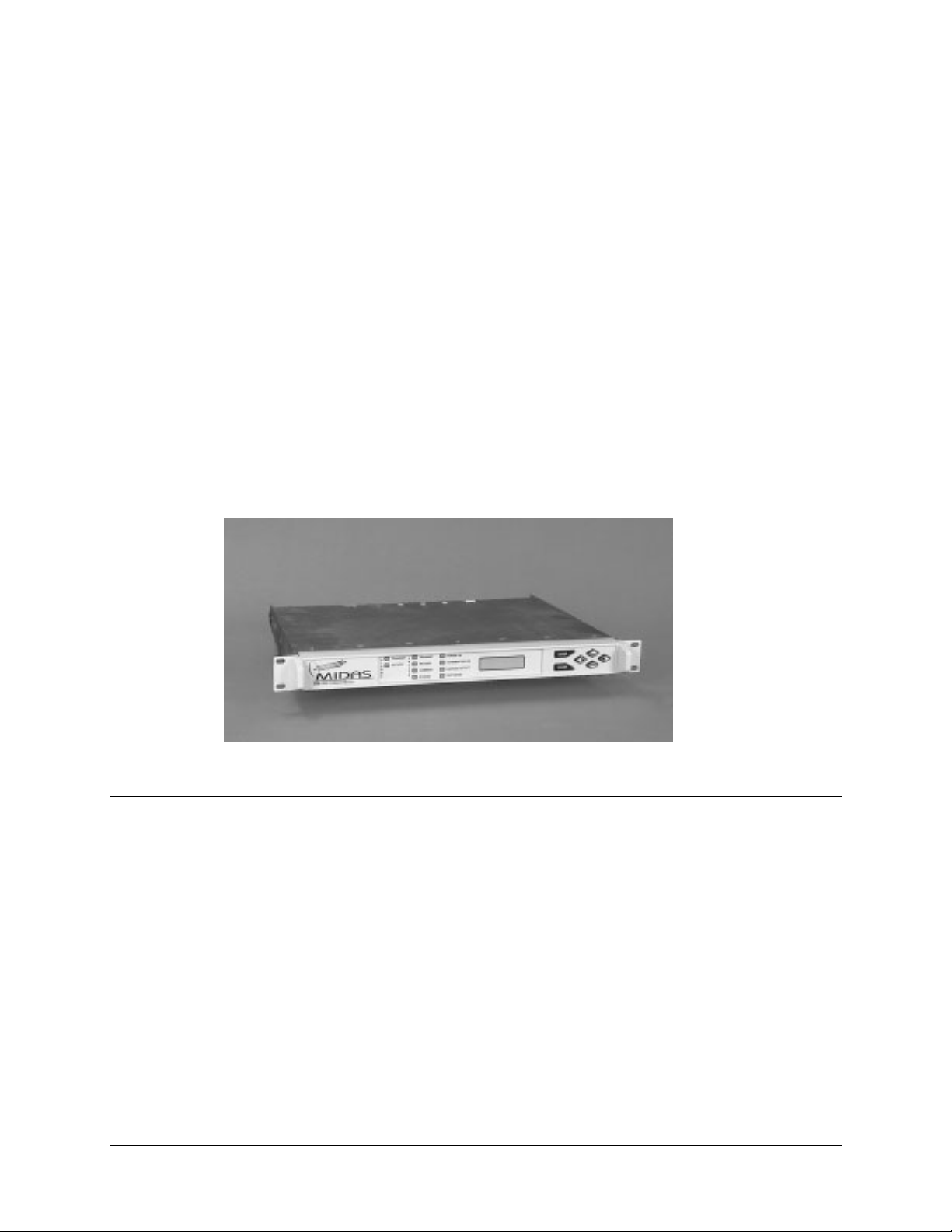
This chapter provides an overview of the SNM-1002 LinkSync Modem, referred to in
this manual as “the modem” (Figure 1-1).
Figure 1-1.
SNM-1002
LinkSync
Modem
1.1 Overview
The SNM-1002 LinkSync™ modem is a high performance, digital modem designed to
provide LinkSync™ functionality for Comtech EF Data ' s Bandwidth-on-demand (BOD)
Multimedia Integrated Digital Access System (MIDAS).
Features of the SNM-1002 include:
• 19.2 kbit/s, QPSK, 1/2 rate continuous demodulator.
• 2.4 kbit/s to 4.375 mbit/s continuous modulator.
• 50/180 MHz operation.
• Extensive online monitoring.
• Built in Self-test.
1–1
Page 20

SNM-1002 LinkSync™ Modem Revision 2
V
A
V
A
A
ALA
A
A
A
Introduction MN/SNM1002.OM
1.2 Mode of Operation
The SNM-1002 is an integral component of the MIDAS Network Management System
(NMS), providing the LinkSync™ monitor and control communication between the NMS
and the MIDAS network.
LinkSync™ provides three key functions for the MIDAS network.
• Automatic Frequency Control (AFC) for all modems within the network.
• Power Management for all active traffic circuits within the network.
• Circuit Disruption capability which allows the NMS to terminate circuits
between any two internal traffic nodes (SNM-1010/1010L)in the network.
The SNM-1002 performs a critical roll for each of these three LinkSync™ capabilities
under the direct control of the MIDAS NMS. Refer to Chapter 4. Theory of Operation.
OPERATOR
WORKSTATION
OPTIONAL PRINTER
(USER SUPPLIED)
ETHERNET
NETWOR K C ONTROL M O D EM
NMS
CONTROLLER
EIA-422
EIA-232
EIA-232
(SNM-1001)
SNM -1001 Network Control Modem
TR
TRANSMIT
NSMIT
F
E
E
RECEI
RECEI
SDT-1200
U
L
R
COMMON
SATELLITE TERMINAL
T
M
S
S
STORED
LinkSync MODEM
(SNM-1002)
ENTER
R
CLE
POWERON
ENTER
TR
NSMITTERON
RRIERDETECT
C
R
CLE
TESTMODE
TM
Figure 1-2. Typical NMS Configuration
IF
(50-180 MHz)
RFT
1–2
Page 21

SNM-1002 LinkSync™ Modem Revision 2
Introduction MN/SNM1002.OM
Figure 1-3. Typical LinkSync Redundancy
1.2.1 Description
The modem contains:
Built-in scramblers/descramblers TX and RX frequency synthesizers
Differential encoder/decoder Multi-rate FEC convolutional Viterbi Decoder
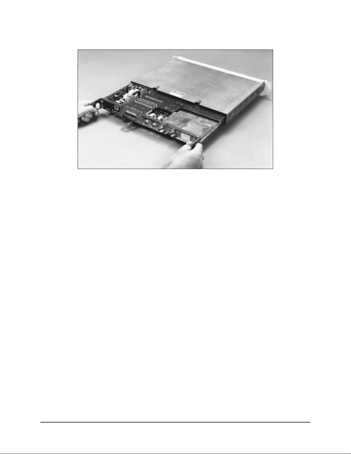
The modem is a complete, self-contained unit in a standard, one-rack unit (1 RU), 19inch (48 cm), rack-mountable enclosure weighing approximately 9 lbs. (4 kg). The unit
was constructed using modular design (Figure 1-4), and consists of from two to five
Printed Circuit Boards (PCBs), depending on the configuration. The modem consists of
two, major, replaceable assemblies as follows:
• Rear panel, main PCB, and power supply
• Upper and lower enclosures (chassis) and the front panel
1–3
Page 22
SNM-1002 LinkSync™ Modem Revision 2
Introduction MN/SNM1002.OM
Figure 1-4. Modular Design
The front panel of the modem contains all Monitor and Control (M&C) function
indicators used for operating the modem. The modem can be operated remotely via the
M&C connection on the rear panel. Refer to Chapter 2 for connector information and
Appendix A for remote control operation information.
1–4
Page 23
SNM-1002 LinkSync™ Modem Revision 2
Introduction MN/SNM1002.OM
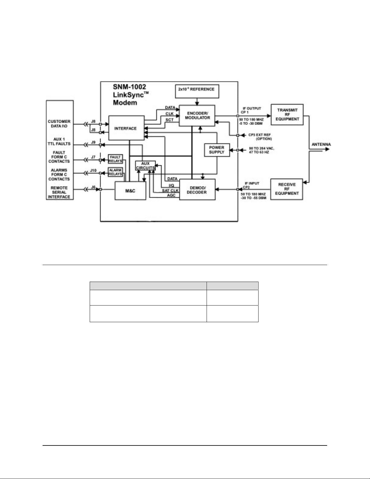
Refer to Figure 1-5 for a system block diagram.
1.3 Options
Option Remarks
Primary Input Power: 90-264 VAC KT/8000-3
-48 VDC KT/8000-4
IF Impedance : 75Ω
50Ω
Figure 1-5. Block Diagram
PL/6093-1
PL/6093-3
1–5
Page 24

SNM-1002 LinkSync™ Modem Revision 2
Introduction MN/SNM1002.OM
1.4 Specifications
1.4.1 Summary Specifications
Table 1-1 lists a summary of the specifications.
Table 1-1. Summary Specifications
Parameter Specification
Operating Frequency Range 50 to 180 MHz, in 1 Hz steps
Modulation Type QPSK
BPSK
Operating Channel Spacing Less than 0.5 dB degradation operating with 2 adjacent-like channels,
each 10 dB higher at 1.3 times the symbol rate.
Digital Interface EIA-422/449 on 37-pin D
Digital Data Rate QPSK, R=1/2, 2.4 kbps to 4.375 Mbps
Scrambling/Descrambling CCIT INTELSAT V.35
Forward Error Correction Viterbi, K=7, Rate 1/2, 3/4, 7/8
Filter Mask Types Closed net (Comtech EF Data)
Modulator
Output Power -5 to –30 dBm, adjustable in 0.1 dB steps
Output Spurious < -55 dBc, 0 to 500 MHz
Output Impedance
Output Return Loss 20 dB
Data Clock Source
Demodulator
Input Power:
Desired Carrier
Adjacent Carriers
Maximum Total
Input Impedance
Input Return Loss 20 dB
Carrier Acquisition Range
Clock Acquisition Range
AGC Output 0 to 10V at 10 mA maximum
75Ω (Optional: 50Ω)
-5
Internal , ± 1 x 10
-30 to –55 dBm
+30 dBc total power within 10 MHz from desired carrier
+40 dBc in-band (0 to 500 MHz)
-5 dBm
75Ω (Optional: 50Ω)
± 35 kHz maximum
± 100 PPM
Default Levels: 0V for –60 dBm
10V for –25 dBm
Levels can be programmed in 0.5V increments.
stability
1–6
Page 25

SNM-1002 LinkSync™ Modem Revision 2
Introduction MN/SNM1002.OM
Table 1-1. Summary Specifications (Continued)
Remote Control Specification
Signal Interface EIA-232
Baud Rate 19.2 kbps
Signals Controlled/Monitored Acquisition Sweep Parameters
Baseband Loopback
Buffer Clock TX/RX/INT
Buffer Size
Code and decode Rate
Data Rate Select
Descrambler On/Off
Descrambler Type
Differential Encoding and Decoding
IF Loopback
Interface Loopback
MOD/DEMOD Spectrum Normal/Invert
Rev Emulation Current/Function
RF Loopback
RX Clock Normal/Invert
RX Frequency
Scrambler On/Off
Scrambler Type
Self Test
Transmitter On/Off
TX Frequency
TX Power
TX/RX Filter Mask
Signals Monitored Corrected BER
Fault Status
Power Supply Voltage
Raw Error Rate
RX Carrier Detect
RX Eb/No
RX Signal Level
Stored Fault Status
Configuration Retention Will maintain current configuration for at least 1 year without power.
Addressing Programmable from 1 to 255 possibilities
Address 0 is reserved for global addressing.
Diagnostic
Diagnostic Features BER Monitoring
Buffer Fill Status Monitoring
Fault Monitoring (include current and stored faults)
IF Loopback
Input IF Power Monitoring
Remote Control via Serial Port
RF Loopback
1–7
Page 26

SNM-1002 LinkSync™ Modem Revision 2
Introduction MN/SNM1002.OM
1.4.2 Environmental and Physical
Table 1-2. Environmental and Physical
Parameter Specifications
Size 1 rack unit (1RU)
1.75" H x 19.0" W x 14" D (4.4 H x 48 W x 36 D cm)
Power Prime power 90 to 264 VAC, 47 to 63 Hz,
40W maximum, fused at 2A
Optional: 38 to 64 VDC
Operating Temperature
Storage Temperature
Humidity 0 to 95% non-condensing
Mounting Standard 19-inch (48.3 cm) rack mounts
Operational Shock When any one corner of the modem is dropped from 1 cm
Survivability Shock and Vibration MIL-STD-810D Method 514.4, Procedure 8, 1 hour/axis
Weight 9 lbs. Maximum
Shipping:
Weight
Size
0 to 50°C (32 to 122° F)
-55 to +70° C (-67 to 158° F)
Note: Front and rear accepts standard rack mount slides
onto a hard surface, the modem will not take any errors or
faults
MIL-STD-167-1
(4 kg Maximum)
15 lbs. (7 kg)
20 x 21 x 9 inch (51 x 53 x 23 cm)
1.5 Bit Error Rate Performance
The following specifications for the Eb/N0 required to achieve 10-3 to 10
different coding configurations. All values are for operating in QPSK mode. Without
coding, the modem provides QPSK operation within 0.8 dB of theoretical for BER in the
range 10
connected back-to-back through an additive white Gaussian noise channel. Refer to
Figure 1-6 for the performance BER curves.
-1
to 10-6. Performance measurements were recorded with transmit and receive IF
Eb/N0 (dB) Specification
BER 1/2 Rate 3/4 Rate 7/8 Rate
10-3 4.2 5.2 6.4
10-4 4.8 6.0 7.2
10-5 5.5 6.7 7.9
10-6 6.1 7.5 8.6
10-7 6.7 8.2 9.2
10-8 7.2 8.8 9.9
-8
BER for
1–8
Page 27

SNM-1002 LinkSync™ Modem Revision 2
Introduction MN/SNM1002.OM
1.5.1 BER Threshold
The modem will have a programmable BER threshold function. This will allow the
operator to set the threshold from 1.0 E-3 to 1.0 E-8.
10-2
-3
10
10-4
10
10
BER
10-7
10
10
-10
10
-5
-6
-8
-9
1/2 Rate 3/4 Rate 7/8 Rate
SPECIFICATIONS
3.0 4.0 5.0 6.0
7.0 8.0 9.0 10.0 11.0
E
(dB)
b/N0
Figure 1-6. Viterbi BER Performance Curves
1–9
Page 28
SNM-1002 LinkSync™ Modem Revision 2
Introduction MN/SNM1002.OM
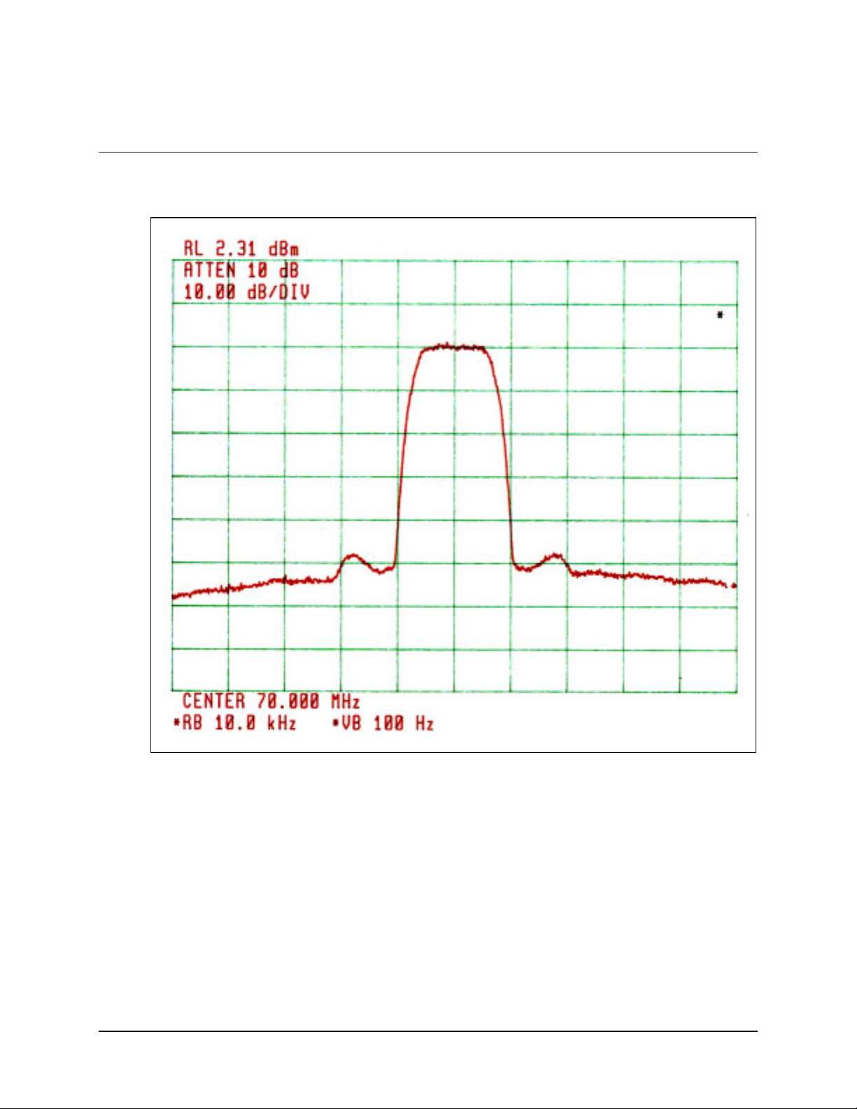
1.6 Typical Spectral Occupancy
Figure 1-7. Typical Spectral Occupancy
1–10
Page 29

SNM-1002 LinkSync™ Modem Revision 2
Introduction MN/SNM1002.OM
1.7 Dimensional Envelope
Note: All dimensions are in English units (centermeters are in parenthesis).
Figure 1-8. SNM-1002 Dimensional Envelope
1–11
Page 30

SNM-1002 LinkSync™ Modem Revision 2
Introduction MN/SNM1002.OM
This page is intentionally left blank.
1–12
Page 31

Chapter 2. INSTALLATION
This chapter provides unpacking and installation instructions, and a description of
external connections information.
The equipment contains parts and assemblies sensitive to damage by
Electrostatic Discharge (ESD). Use ESD precautionary procedures when
CAUTION
touching, removing, or inserting PCBs.
2.1 Unpacking
The modem and manual are packaged in pre-formed, reusable, cardboard cartons
containing foam spacing for maximum shipping protection.
Do not use any cutting tool that will extend more than 1 inch into the
container. This can cause damage to the modem.
CAUTION
Unpack the modem as follows:
1. Cut the tape at the top of the carton indicated by OPEN THIS END.
2. Remove the cardboard/foam space covering the modem.
3. Remove the modem, manual, and power cord from the carton.
4. Save the packing material for storage or reshipment purposes.
5. Inspect the equipment for any possible damage incurred during shipment.
6. Check the equipment against the packing list to ensure the shipment is correct.
7. Refer to Section 2.2 for installation instructions.
2–1
Page 32

SNM-1002 LinkSync Modem Revision 2
Installation MN/SNM1002.OM
2.2 Installation
The modem arrives fully assembled from the factory. After unpacking the modem, install
the modem as follows:
1. If required, install the mounting bracket in equipment rack (Figure 2-1). Install
and tighten the bracket bolts.
2. Loosen the screw with flat washer located on the left side of modem chassis.
Mount the modem chassis into the equipment rack and slide the screw with flat
washer through the slot of the mounting bracket. Tighten the screw sufficiently to
allow the modem chassis to slide in the bracket.
3. Connect the cables to the proper locations on the rear panel. Refer to Section 2.3
for connector pinouts, placement, and function.
4. Connect the primary power cable to the power source. Before turning on the
power switch, become familiar with the front panel operation in Chapter 3.
5. If problems exist with the installation, refer to Chapter 5 for troubleshooting
information.
2–2
Page 33

SNM-1002 LinkSync Modem Revision 2
Installation MN/SNM1002.OM
Figure 2-1. Installation of the Mounting Bracket
2–3
Page 34

SNM-1002 LinkSync Modem Revision 2
Installation MN/SNM1002.OM
2.2.1 Typical Single-Thread Cable Installation
Note: Cables may be procured from Comtech EF Data by contacting Comtech EF Data
Network Customer Support department for information.
1. Connect supplied Y-Cable (Figure 2-2) as follows:
a. Connect the supplied-cable base connector to the FASTCOM card.
b. Connect supplied-cable Port 1 connector to the Comtech EF Data
supplied EIA-422 cable from SNM-1001 Modem.
c. Cable Port 2 connector is not connected.
2. Connect 9-pin EIA-232 cable from Controller Server COM 1 port to SNM-1001
Remote port (J6).
a. If non-redundant SNM-1001, the following remote settings are required:
• EIA-232
• 19.2 Baud rate
• 8N1
3. Connect 9-pin EIA-232 cable from Controller Server COM 2 port to SNM-1002
Remote port (J6).
4. Connect 25-pin pre-programmed dongle (security key) to Controller Server
25-pin I/O port.
Figure 2-2. Typical Single-Thread Installation
2–4
Page 35

SNM-1002 LinkSync Modem Revision 2
Installation MN/SNM1002.OM
Item No. Cable Description From To
1 Comtech EF Data
Supplied
2 CA/5684 Supplied Y-Cable Port 1 of the SNM-1001
3 EIA-232 MIDAS Controller COM 2 SNM-1002 Remote port (J6)
4
EIA-232 MIDAS Controller COM 1 SNM-1001Remote port (J6)
FASTCOM Card CA/5684
2.2.2 Redundant LinkSync (Network Control) Modem Installation
A typical redundant wiring schematic is included to assist the user in establishing a
redundant configuration. The following table can assist the user in cable selection and
location. One or both of the 1:1 redundant configurations can be installed in a MIDAS
System. Figure 2-3 shows both Network Control Modem and LinkSync Modem
Redundancy.
Item No. Cable Description From To
1 CA/5684 MIDAS Controller SMS-301 J1 COM
2 EIA-422 37-pin SMS-301 (J2) SNM-1001(A) (J8)
3 EIA-422 37-pin SMS-301 (J3) SNM-1001 (B) (J8)
4 BNC SMS-301 (J4) (TX-IF) Combiner
5 BNC SMS-301 (J8) (RX-IF) Combiner
6 BNC SMS-301 (J9) A SNM-1001(A) CP2 TX/IF
7 BNC SMS-301 (J6) B SNM-1001(B) CP1 TX/IF
8 BNC SMS-301 (J7) B SNM-1001(B) CP2 RX/IF
9 BNC SMS-301 (J5) A SNM-1001(A) CP1 TX/IF
10 EIA-232 9-pin
Network Control Modem
11 EIA-232 SMS-301 (J10)
12 EIA-422 37-pin SMS-301 (J2) SNM-1002 (A) Data I/O
13 EIA-422 37-pin SMS-301 (J3) SNM-1002 (B) Data I/O
14 EIA-232 9-pin
15 BNC SMS-301 (J9) A SNM-1002 A) CP2 RX-IF
16 BNC SMS-301 (J8) RX-IF Combiner
17 BNC SMS-301 (J4) TX-IF Combiner
18 BNC SMS-301 (J5) A SNM-1002(A) CP1 TX-IF
19 BNC SMS-301 (J7) B SNM-1002(B) CP2 RX-IF
LinkSync Modem
20 BNC SMS-301 (J6) B SNM-1002(B) CP1 TX-IF
21 EIA-232 SMS-301 (J10)
Ribbon Cable
Ribbon Cable
SMS-301 (J13)
Modem COM
Remote Control
SMS-301 (J13)
Modem COM
Remote Control
SNM-1001(A) (J6) Remote
SNM-1001(B) (J6) Remote
MIDAS Controller COM1
SNM-1002(A) (J6) Remote
SNM-1002(B) (J6) Remote
MIDAS Controller COM2
2–5
Page 36

SNM-1002 LinkSync Modem Revision 2
Installation MN/SNM1002.OM
Figure 2-3. Typical Redundant Wiring Schematic
2–6
Page 37

SNM-1002 LinkSync Modem Revision 2
Installation MN/SNM1002.OM
2.3 Rear Panel Connections
The rear panel connectors provide all necessary external connections between the modem
and other equipment.
Table 0-1 lists these connectors, and Figure 2-4 shows their locations.
Figure 2-4. View of Rear Panel
Table 0-1. Rear Panel Connectors
Name
REMOTE J6 9-pin D Remote Interface
FAULT
Connector is not used.
DATA I/O J8 37-pin D EIA-422
AUX 1
Connector is not used.
ALARMS
Connector is not used.
TX/IF OUTPUT CP1 BNC RF Output
RX/IF INPUT CP2 BNC RF Input
EXTERNAL REF CP3 BNC Input
AC INPUT NONE IEC
GROUND NONE 10-32 Stud
REF DES Connector Type
J7 9-pin D FORM C Fault Relay Contacts
J9 9-pin D (TTL) Faults
Satellite Clock
Demod I/Q
Automatic Gain Control (AGC) Out
J10 9-pin D FORM C Alarm
Relay Contacts
Function
Note: The European EMC Directive (EN55022, EN50082-1) requires using properly shielded
cables for DATA I/O. These cables must be double-shielded, ensuring a continuous ground
shield.
2–7
Page 38

SNM-1002 LinkSync Modem Revision 2
Installation MN/SNM1002.OM
2.3.1 Remote Connector and Pinouts (J6)
The remote connector is a 9-pin female D connector (J6) located on the rear panel of the
modem. Screw locks are provided for mechanical security of the mating connector.
The remote connector interfaces the M&C functions to the MIDAS Controller. This is an
EIA-232 DCE interface. Refer to Appendix A for a description of the remote interface.
Refer to Table 0-2 for pinout information.
Table 0-2. Remote Connector and Pinouts (J6)
EIA-232
Pin # Name
1
2 RD (RX)
3 TD (TX)
4
5 GND
6 DSR
7 RTS
8 CTS
9
2.3.2 Data I/O Interface Connector (J8)
This connector is only utilized when the modem is operating in a Redundant LinkSync
Configuration. In a Redundant LinkSync Configuration, the Data I/O cable connects
between an SNM-301 1:1 Switch and J8 of the LinkSync modem. Refer to Chapter 1,
Figure 1-3.
2.3.3 RF Output Connector (CP1)
CP1 is a BNC connector for the transmit IF signal. The standard output impedance is 75Ω,
and the output power level is -5 to -30 dBm. In normal operation, the output will be a
QPSK- or BPSK-modulated signal between 50 and 180 MHz, in 1 Hz steps.
2.3.4 RF Input Connector (CP2)
CP2 is a BNC connector for the receive IF signal. The standard input impedance is 75. For
normal operation, the desired carrier signal level should be between -30 and -55 dBm.
Signals between 50 and 180 MHz are selected and demodulated to produce clock and data
at the Data I/O connector.
2–8
Page 39

SNM-1002 LinkSync Modem Revision 2
Installation MN/SNM1002.OM
2.3.5 External Reference (CP3)
CP3 is a BNC connector for an external reference. The input impedance is 75Ω. For
normal operation, the reference signal is
≥ 0 dBm.
2.3.6 AC Power Connector
The AC power is supplied to the SNM-1002 by a standard, d etachab le, non-locking,
3-prong power cord. Refer to the following listing for AC power specifications.
Input power
Input voltage
Connector type
Fuse protection
50W max.
90 to 264 VAC, 47 to 63Hz.
Note: Unit switches ranges automatically.
IEC
1A slo-blo line and neutral fusing 5 mm type fuses.
2.3.7 DC Power - Optional
For DC supplied units, the DC Power is supplied by terminal lugs installed on the back
panel. Refer to the following table for specifications
Input power
Input voltage
Connector type
Fuse protection
50W max.
38 to 64 VDC.
Terminal Lug
1A slo-blo 5 mm type fuses.
2.3.8 Ground Connector (GND)
A #10-32 stud on the rear panel of the modem is used for connecting a common chassis
ground among all equipment.
Note: The AC power connector provides the safety ground.
2–9
Page 40

SNM-1002 LinkSync Modem Revision 2
Installation MN/SNM1002.OM
This page is intentionally left blank.
2–10
Page 41

Chapter 3. OPERATION
3.1 Front Panel
Note: Front panel operation of the LinkSync modem is only required for initial
installation for setting the remote communication parameters. Under normal operation,
the MIDAS NMS configures and controls the LinkSync for all of the functions it
provides. A complete menu tree is shown for navigational purposes only.
The modem front panel (Figure 3-1) enables control of modem configurations parameters
and displays the modem status.
Figure 3-1. Front Panel View
The front panel features include:
• 32-character, 2-line LCD display
• 6-button keypad for local control
• 10 LEDs to provide overall status at a glance
3–1
Page 42

SNM-1002 LinkSync Modem Revision 2
Operation MN/SNM1002.OM
3.1.1 LED Indicators
The 10 LEDs on the front panel indicate:
• General modem summary faults
• Status
• Alarms
The indicators are defined in Table 3-1 as follows:
Table 3-1. LED Indicators
Name LED Meaning
Faults
Transmit Red A fault condition exists in the transmit chain.
Receive Red A fault condition exists in the receive chain.
Common Red A common equipment fault condition exists.
Stored Yellow A fault has been logged and stored.
The fault may or may not be active.
Status
Power On Green Power is applied to the modem.
Transmitter On Green Transmitter is currently on.
This indicator reflects the actual condition of the transmitter, as
opposed to the programmed condition.
Carrier Detect Green Decoder is locked.
Test Mode Yellow Flashes when the modem is in a test configuration.
Alarms
Transmit Yellow A transmit function is in an alarm condition.
Receive Yellow A receive function is in an alarm condition.
3–2
Page 43

SNM-1002 LinkSync Modem Revision 2
Operation MN/SNM1002.OM
3.1.2 Front Panel Keypad
The front panel keypad permits local operation of the modem. The keypad consists of six
keys (Figure 3-2). It is locked out for normal use.
ENTER
CLEAR
Figure 3-2. Keypad
Each key provides one or more logical functions. These functions are defined in the
following table.
ENTER This key is used to select a displayed function or to execute a modem
configuration change.
CLEAR This key is used to back out of a selection or to cancel a configuration change
which has not been executed using [ENTER]. Pressing [CLEAR] generally
returns the display to the previous selection.
Left and Right
Diamond Keys
Top and Bottom
Diamond Keys
These keys are used to move to the next selection or to move the cursor for
certain functions.
Note: Throughout this chapter, [
diamond keys.
These keys are used primarily to change configuration data (numbers). At times,
they are also used to move from one section to another.
Note: Throughout this chapter, [
diamond keys.
←] and [→] are used to indicate left and right
↑] and [↓] are used to indicate top and bottom
The modem responds by beeping whenever a key is pressed:
• A single beep indicates a valid entry and the appropriate action was taken.
• A double beep indicates an invalid entry or a parameter is not available for
operation.
3–3
Page 44

SNM-1002 LinkSync Modem Revision 2
Operation MN/SNM1002.OM
3.2 Menu System
Use the Main menu in Figure 3-3 as a quick reference for accessing the modem functions.
When the modem power is applied, the base level of the menu system displays the
sign-on message:
• Line 1 of the sign-on message is the modem type.
• Line 2 is the node address.
The main level of the menu system is Function Select. To access this level from the
sign-on message, press the [←] or [→] keys. From the Function Select menu, select one
of the functional categories:
• Configuration
• Monitor
• Faults/Alarms
• Stored Faults/Alarms
• Utility
Press [←] or [→] to move from one selection to another. When line 2 displays the desired
function, select that level by pressing [ENTER]. After entering the appropriate functional
level, press [←] or [→] to move to the desired function.
To view the modem’s configuration, enter the Configuration level from the Function
Select menu. Once in the Configuration menu, press [←] or [→] to scroll through the
Configuration menu selection:
• Modulator
• Demodulator
• Interface
• Save
• Recall
Press [ENTER] to select the desired Configuration menu option. To view the options for
the selected configuration parameters, press [←] or [→].
Notes:
1. Menus or commands that are specific to certain modem configurations are only
accessible after selecting the appropriate modem configuration. This prevents
incompatible parameters from accidentally being selected.
3. All of the windows are accessible in the Custom mode. Take caution not to select
incompatible parameters, as the modem does not shut out incompatible command
choices in the Custom mode.
3–4
Page 45

SNM-1002 LinkSync Modem Revision 2
Operation MN/SNM1002.OM
3.3 Front Panel Menu
SELECT
CONFIGURATION
MONITOR
FAULTS/ALARMS
STORED FLTS/ALMS
UTILITY
FACTORY SETUP (NOT APPL ICABLE
MODULATOR
DEMODULATOR
INTERFACE
SAVE
RECALL
RAW BER
CORRECTED BER
EB/NO
RECEIVE SIGNAL
SWEEP FREQUENCY
BUFFER FILL
MODULATOR
DEMODULATOR
TX INTERFACE
RX INTERFACE
COMMON
MODULATOR
DEMODULATOR
TX INTERFACE
RX INTERFACE
COMMON
CLEAR
MODULATOR
DEMODULATOR
INTERFACE
SYSTEM
MODEM TYPE
CODE/DATA RATE
TX-IF FREQUENCY
TX-IF OUTPUT
TX POWER LEVEL
SCRAMBLER
DIFF ENCODER
CARRIER MODE
MODEM REFERENCE
CODE/DATA RATE
RX-IF FREQUENCY
DESCRAMBLER
DIFF DECODER
RF LOOP BACK
IF LOOP BACK
BER THRESHOLD
SWEEP CENTER
SWEEP RANGE
REACQUISITION
TX CLOCK SOURCE
TX CLOCK PHASE
EXT-CLK FREQ
BUFFER CLOCK
RX CLOCK PHASE
B-BAND LOOP BACK
BUFFER SIZE
BUFFER CENTER
LOOP TIMING
ASSIGNED FILTERS
MOD POWER OFFSET
MODULATOR TYPE
ENCODER TYPE
TX BPSK OREDERING
MOD SPECTRUM
TX SYMBOL RATE
ASSIGNED FILTERS
DEMODULATOR TYPE
DECODER TYPE
RX BPSK ORDERING
DEMOD SPECTRUM
RX SYMBOL RATE
TX OVERHEAD TYPE
RX OVERHEAD TYPE
TX TERR INTERFACE
RX TERR INTERFACE
BUFFER PROGRAM
FRAMING STRUCTURE
RTS TX-IF CNTRL
TX DATA PHASE
RX DATA PHASE
CTS DELAY
TIME/DATE
REMOTE BAUD RATE
REMOTE ADDRESS
REMOTE TYPE
OPERATION MODE
YEAR DISPLAY
TEST MODE STATUS
LAMP TEST
SELF TEST
DISPLAY CONTRAST
M&C FIRMWARE
BOOT FIRMWARE
FPGA FIRMWARE
DEMO MODE
EXT AGC: MAX PWR
EXT AGC: MIN PWR
MASTER RESET
MODEM TYPE
MODEM EMULATION
REV EMULATION
MODEM OPTIONS
LOCAL MODEM AUPC
MODEM SERIAL
CONFIGURATION CODE
Figure 3-3. Main Menu
3–5
Page 46

SNM-1002 LinkSync Modem Revision 2
Operation MN/SNM1002.OM
Note: The following menus tree shows the modem functions available for an SNM-1002
LinkSync Modem. The defaulkt settings used when deployed in a MIDAS Network are
underlined.
3.4 OPENING SCREEN
SNM 1002
Ver:X.X.X
3.4.1 FUNCTION SELECT:CONFIGURATION
FUNCTION SELECT
CONFIGURATION
The main level of the menu system is Function Select. To access this level from the
sign-on message, press the [←] or [→] keys. From the Function Select menu, select one
of the functional categories:
• Configuration
• Monitor
• Faults/Alarms
• Stored Faults/Alarms
• Utility
Press [←] or [→] to move from one selection to another. When line 2 displays the desired
function, select that level by pressing [ENTER]. After entering the appropriate functional
level, press [←] or [→] to move to the desired function.
3–6
Page 47

SNM-1002 LinkSync Modem Revision 2
Operation MN/SNM1002.OM
3.4.1.1 CONFIGURATION:MODULATOR
CONFIGURATION
MODULATOR
To view the modem’s configuration, enter the Configuration level from the Function
Select menu. Once in the Configuration menu, press [←] or [→] to scroll through the
Configuration menu selection:
• Modulator
• Demodulator
• Interface
• Save
• Recall
Press [ENTER] to select the desired Configuration menu option. To view the options for
the selected configuration parameters, press [←] or [→].
3.4.1.1.1 MODULATOR: CODE RATE/TYPE
TX-X QPSK 1/2
19.200 kbps
Transmit code rate/type as follows:
TX-A QPSK 1/2 19.200 kbps
TX-B QPSK 1/2 19.200 kbps
TX-C QPSK 1/2 19.200 kbps
TX-D QPSK 1/2 19.200 kbps
TX-V QPSK 1/2 19.200 kbps
Upon entry, the current transmitter rate is displayed.
3–7
Page 48

SNM-1002 LinkSync Modem Revision 2
Operation MN/SNM1002.OM
3.4.1.1.2 MODULATOR:TX-IF FREQENCY
TX-IF FREQUENCY
70.000000 MHz
Displays the modulator TX IF frequency between 50 and 180 MHz, in 1 Hz steps.
Upon entry, the current transmitter frequency is displayed with the flashing cursor on the
first character. Press [← ] or [→] to move the flashing cursor, and [↑ ] or [↓ ] to increase
or decrease the digit at the flashing cursor. Press <ENTER> to execute the change.
3.4.1.1.3 MODULATOR:TX-IF OUTPUT
TX-IF OUTPUT
ON
Displays the modulator output status, either On
Upon entry, the current TX-IF output is displayed with the flashing cursor on the first
character. Press [↑ ] or [↓ ] to On or Off. Press <ENTER> to execute the change.
or Off.
3.4.1.1.4 MODULATOR:TX POWER LEVEL
TX POWER LEVEL
-10.0 dBm
Displays the modulator output level from:
• -5.0 to –30.0 dBm (Normal Range)
Upon entry, the current TX power level is displayed with the flashing cursor on the first
character. Press [← ] or [→] to move the flashing cursor, and [↑ ] or [↓ ] to increase or
decrease the digit at the flashing cursor. Press <ENTER> to execute the change.
3–8
Page 49

SNM-1002 LinkSync Modem Revision 2
Operation MN/SNM1002.OM
3.4.1.1.5 MODULATOR:SCRAMBLER
SCRAMBLER
ON
Displays the scrambler status, either On
Upon entry, the current scrambler is displayed with the flashing cursor on the first
character. Press [↑ ] or [↓ ] to change the carrier mode. Press <ENTER> to execute the
change
or Off.
3.4.1.1.6 MODULATOR:DIFF. ENCODER
DIFF. ENCODER
ON
Displays the differential encoder status, either On
Upon entry, the current differential decoder is displayed with the flashing cursor on the
first character. Press [↑ ] or [↓ ] to change the carrier mode. Press <ENTER> to execute
the change.
or Off.
3–9
Page 50

SNM-1002 LinkSync Modem Revision 2
Operation MN/SNM1002.OM
3.4.1.1.7 MODULATOR:CARRIER MODE
CARRIER MODE
NORMAL-MODULATED
Displays the carrier mode of operation as follows:
Normal-Modulated
Center-CW
Offset-CW
Dual-CW
Upon entry, the current carrier mode is displayed with the flashing cursor on the first
character. Press [↑ ] or [↓ ] to change the carrier mode. Press <ENTER> to execute the
change.
The carrier mode in normally in this Modulated position.
Generates a carrier at the current modulator frequency. This can be used to
measure the output frequency.
Generates a single, upper, side-band-suppressed carrier signal. The upper sideband is at one-quarter of the symbol rate from the carrier. When inverted
spectrum is selected, this generates a single, lower, side-band-suppressed
carrier.
Generates a dual side-band suppressed carrier signal. Side-bands are at one-half
of the symbol rate from the carrier. This is used to check the channel balance and
carrier null.
3.4.1.1.8 MODULATOR:MODEM REFERENCE
MODEM REFERENCE
INTERNAL
Displays the following references to the modulator:
• INTERNAL
• EXT1, EXT5, EXT10, and EXT20 MHz
Note: If any EXT REF is selected for the modem reference and there is no input to CP3,
the modem will detect an alarm and switch to the INTERNAL clock.
Upon entry, the current modem reference is displayed with the flashing cursor on the first
character. Press [↑ ] or [↓ ] change the modem reference. Press <ENTER> to execute the
change.
3–10
Page 51

SNM-1002 LinkSync Modem Revision 2
Operation MN/SNM1002.OM
3.4.1.2 CONFIGURATION:DEMODULATOR
CONFIGURATION
DEMODULATOR
3.4.1.2.1 DEMODULATOR:CODE RATE/TYPE
RX-X QPSK 1/2
19.200 kbps
Receive code rate/type as follows:
RX-A QPSK 1/2 19.200 kbps
RX-B QPSK 1/2 19.200 kbps
RX-C QPSK 1/2 19.200 kbps
RX-D QPSK 1/2 19.200 kbps
RX-V QPSK 1/2 19.200 kbps
Upon entry, the current transmitter rate is displayed. Press [↑ ] or [↓ ] change the
assigned filter. Press <ENTER> to execute the change.
3.4.1.2.2 DEMODULATOR:RX-IF FREQUENCY
RX-IF FREQUENCY
70.000000 MHZ
Displays the demodulator receive frequency, between 50 and 180 MHz, in 1 Hz steps.
Upon entry, the current RF-IF frequency is displayed. Press [↑ ] or [↓ ] change the
assigned filter. Press <ENTER> to execute the change.
3–11
Page 52

SNM-1002 LinkSync Modem Revision 2
Operation MN/SNM1002.OM
3.4.1.2.3 DEMODULATOR:DESCRAMBLER
DESCRAMBLER
ON
Displays the descrambler status, either On
Upon entry, the current descrambler is displayed. Press [↑ ] or [↓ ] change the assigned
filter. Press <ENTER> to execute the change.
or Off.
3.4.1.2.4 DEMODULATOR:DIFF.DECODER
DIFF. DECODER
ON
Displays the differential decoder status, either On
Upon entry, the current differential decoder is displayed. Press [↑ ] or [↓ ] change the
assigned filter. Press <ENTER> to execute the change.
or Off.
3.4.1.2.5 DEMODULATOR:RF LOOP BACK
RF LOOP BACK
OFF
Displays the RF loop back status, either On or Off
Upon entry, the current RF loop back is displayed. Press [↑ ] or [↓ ]. Press <ENTER> to
execute the change.
.
3–12
Page 53

SNM-1002 LinkSync Modem Revision 2
Operation MN/SNM1002.OM
3.4.1.2.6 DEMODULATOR:IF LOOP BACK
IF LOOP BACK
OFF
Displays the IF loop back status, either On or Off
Upon entry, the current IF loop back is displayed. Press [↑ ] or [↓ ]. Press <ENTER> to
execute the change.
.
3.4.1.2.7 DEMODULATOR:BER THRESHOLD
BER THRESHOLD
NONE
Displays the BER threshold .
If the BER threshold set is exceeded, a receive fault will be indicated by the modem
status indicators. BER threshold may be set from 1.0 E-3 to 1.0 E-8, or may be disabled
by specifying NONE
Upon entry, the current BER threshold is displayed. Press [↑ ] or [↓ ]. Press <ENTER> to
execute the change.
.
3.4.1.2.8 DEMODULATOR:SWEEP CENTER
SWEEP CENTER
+ 0 HZ
Displays the sweep center frequency for the directed sweep function. When in directed
sweep, the value from the sweep monitor screen (when the modem was last locked)
should be entered for the sweep center frequency. The sweep center frequency can be set
in the range from –35000 to +35000 Hz. Default: 0 Hz
Upon entry, the current sweep center frequency is displayed with the flashing cursor on
the first character. Press [← ] or [→] to move the flashing cursor, and [↑ ] or [↓ ] to
increase or decrease the digit at the flashing cursor. Press <ENTER> to execute the
change.
3.4.1.2.9 DEMODULATOR:SWEEP RANGE
3–13
.
Page 54

SNM-1002 LinkSync Modem Revision 2
Operation MN/SNM1002.OM
SWEEP RANGE
60000 HZ
Displays the overall travel of the sweep width range during acquisition in the directed
sweep mode. The sweep width may be set from 0 to 70000 Hz. Default: 60000 Hz
When set at 70000 Hz, the modem is in Normal acquisition mode. The smaller the range,
the faster the modem will lock, provided the receive carrier center frequency is within the
RX-IF frequency sweep range.
.
3.4.1.2.10 DEMODULATOR:REACQUISITION
REACQUISITION
0 SECONDS
Displays the sweep reacquisition mode time duration. This is the time that the modem
will remain in a narrow sweep after loss of acquisition. After this timer runs out, the
modem will return to the normal acquisition sweep. The reacquisition time is 0 to 999
seconds. Default: 0 seconds
.
3–14
Page 55

SNM-1002 LinkSync Modem Revision 2
Operation MN/SNM1002.OM
3.4.1.3 CONFIGURATION:INTERFACE
CONFIGURATION
INTERFACE
3.4.1.3.1 INTERFACE:TX CLOCK SOURCE
TX CLOCK SOURCE
SCT (INTERNAL)
Programs the clock source for the modem transmitter clock to the following
configurations:
TX TERRESTRIAL
SCT (INTERNAL)
RX (SATELLITE)
EXT CLOCK
Upon entry, the current TX clock source is displayed. Press [↑ ] or [↓ ] to make the
selection. Press <ENTER> to execute the change.
Sets the TX clock to recover timing from the incoming clock/data.
Sets the TX clock to operate from the modem internal clock (this also is the
fallback clock).
Note: When loop timing is enabled, SCT (LOOP) is displayed instead of SCT
(INTERNAL).
Sets the RX clock to recover timing from the output clock/data.
Sets the TX clock to operate from the EXT-CLK clock. Transmit clock source
must be phase/frequency locked to the data that is being transmitted. The
correct frequency must be programmed into EXT-CLK FREQ.
3–15
Page 56

SNM-1002 LinkSync Modem Revision 2
Operation MN/SNM1002.OM
3.4.1.3.2 INTERFACE:TX CLOCK PHASE
TX CLOCK PHASE
INVERT
Programs the TX clock phase to AUTO, NORMAL, INVERT
Upon entry, the current TX clock phase is displayed. Press [↑ ] or [↓ ] to make the
selection. When AUTO is s elected, the modem will automatically select NORMAL or
INVERT to properly phase the TX clock with the TX data. Press <ENTER> to execute
the change.
.
3.4.1.3.3 INTERFACE:EXT-CLK FREQ
EXT-CLK FREQ
1544.000 KHZ
Programs the external reference clock input frequency between 8.0 kHz and 10.0 MHz.
Default: 1544 kHz
Note: The clock rate must be equal to the data rate unless the asymmetrical loop timing
option is present.
This clock frequency can be any multiple of 600 Hz from 2.4 to 64 kHz, and can be any
multiple of 8 kHz from 64 kHz to 4.376 MHz.
This can be used for the Doppler/plesiochronous buffer reference. It can be a reference to
SCT. Use the master clock input on J8 for the external master reference. The EXT REF
on CP3 only allows for 1, 5, 10, and 20 MHz external reference input.
Upon entry, the current setting for the external reference is displayed. Press [←] or [→]
to increment or decrement the digit at the flashing cursor. Press [ENTER] to execute the
change.
.
3–16
Page 57

SNM-1002 LinkSync Modem Revision 2
Operation MN/SNM1002.OM
3.4.1.3.4 INTERFACE:BUFFER CLOCK
BUFFER CLOCK
RX (SATELLITE)
Programs the interface buffer output clock to one of the following modes:
RX (SATELLITE)
SCT (INTERNAL)
EXT. CLOCK
TX TERRESTRIAL
INSERT CLOCK
Upon entry, the current setting of the plesiochronous buffer clock is displayed. Press [↑] or
[↓] to make the selection. Press [ENTER] to execute the change.
Sets the output buffer clock to the satellite clock. (This is a Bypass.)
Sets the buffer clock to operate from the modem internal clock. This is
also the fallback clock.
Sets this clock source to the external clock.
Sets the buffer output clock to recover timing from the incoming TX data
clock.
Selects the recovered clock from the insert send data input received from
the terrestrial equipment.
3.4.1.3.5 INTERFACE:RX CLOCK PHASE
RX CLOCK PHASE
NORMAL
Programs the RX clock phase to Normal
Upon entry, the status of the RX Clock is displayed. Press [↑] or [↓] to make the selection.
Press [ENTER] to execute the change.
or Inverted.
3–17
Page 58

SNM-1002 LinkSync Modem Revision 2
/
Operation MN/SNM1002.OM
3.4.1.3.6 INTERFACE:B-BAND LOOP BACK
B-BAND LOOP BACK
OFF
Programs the modem for baseband loopback operation, On or Off
When baseband loopback is turned on, the data and timing signals are switched from the
demodulator to the modulator on the modem side of the interface. The DTE baseband
signals are also looped back from the transmitter data and clock to receiver data and clock
on the customer side of the interface. This is a bi-directional loopback of the baseband data.
Refer to figure 3-4 for a block diagram of baseband loopback operation.
Upon entry, the status is displayed. Press [↑] or [↓] to make the selection. Press [ENTER] to
execute the change.
.
CUSTOMER
DATA
REMOTE SERIAL
INTERFACE
FAULT INDICATORS
IBS OR IDR
INTERFACE
SATELLITE MODEM
ENCODER/
MODULATOR
MICRO-
COMPUTER
DEMODULATOR
DECODER
POWER SUPPLY
TRANSMIT RF
EQUIPMENT
AC POWER
RECEIVE RF
EQUIPMENT
Figure 3-4. Baseband Loopback
Note: When baseband loopback is turned on, data is looped back on the customer side of the
interface. This is a bi-directional loopback of the baseband data. This test mode will verify the
customer equipment and cabling between the modem and the customer equipment. The baseband
loopback is not bi-directional in D&I.
ANTENNA
3–18
Page 59

SNM-1002 LinkSync Modem Revision 2
Operation MN/SNM1002.OM
3.4.1.3.7 INTERFACE:BUFFER SIZE
BUFFER SIZE
0 (BYPASS)
Sets the size of the buffer, 32 to 262144 bits, 1 to 99 mS , or 0 (Bypass)
Upon entry, the current buffer length is displayed. Press [↑] or [↓] to select the desired
buffer size. The buffer size is displayed in seconds or bits. Enter the Utility Interface menu
to change the buffer units to seconds or bits.
• If selecting seconds, choose from 1 to 99 ms, in increments of 1 ms,
or 0 (Bypass).
• If selecting bits, choose from 32 to 262144 bits, in increments of 16 bits.
• Press [ENTER] to execute the change.
Note: To have the modem calculate the plesiochronous shift, set the buffer units to ms.
When a specific buffer depth is desired, set the buffer units to bits. Select bits or ms from
the Utility Interface menu.
3.4.1.3.8 INTERFACE:BUFFER CENTER
BUFFER CENTER
YES/NO
This configuration function is used to center the buffer. Choosing YES centers the buffer.
Press <ENTER> twice to center the buffer.
3.4.1.3.9 INTERFACE:LOOP TIMING
3–19
Page 60

SNM-1002 LinkSync Modem Revision 2
Operation MN/SNM1002.OM
LOOP TIMING
OFF
The SCT output will become phase-locked to the RX satellite clock.
TX and RX data rates must be equal unless the asymmetrical loop timing option is On or
.
Off
Upon entry, the status is displayed. Press [↑] or [↓] to make the selection. Press [ENTER]
to execute the change.
3.4.1.4 CONFIGURATION:SAVE
CONFIGURATION
SAVE
The Configuration Save menu allows programming of configuration parameters into
memory on the M&C. There are five memory locations that may be used to store specific
configuration setups that are used frequently. After changing the configuration
parameters to the desired settings, enter the Configuration Save menu and select memory
location 1 through 5.
Press [ENTER] to execute the save.
3.4.1.5 CONFIGURATION:RECALL
CONFIGURATION
RECALL
The Configuration Recall menu allows the user to recall a previously saved configuration
setup. Upon entry, select memory location 1 through 5 by pressing [↑] or [↓].
Press [ENTER] to execute the recall.
3.4.2 FUNCTION SELECT:MONITOR
3–20
Page 61

SNM-1002 LinkSync Modem Revision 2
Operation MN/SNM1002.OM
FUNCTION SELECT
MONITOR
3.4.2.1 MONITOR:RAW BER
RAW BER
NO DATA
Displays the current BER or “No Data” (if carrier is not locked).
Range: < m.m E-e to > m.m E-e.
Note: Low limit is based on performance. High limit is based on data/code rate.
3.4.2.2 MONITOR:CORRECTED BER
CORRECTED BER
NO DATA
Displays the current corrected BER or “No Data” (if carrier is not locked).
Range: 1.0 E-3 to 1.0 E-12.
Note: Low limit is based on performance. High limit is 1.0 E-12.
3.4.2.3 MONITOR:EB/NO
EB/NO
16.0
Displays the current Eb/N0 or “No Data” (if carrier is not locked).
Range: 2.0 to 16.0 dB.
Note: Low limit is based on the data rate. High limit is 16.0 dB.
3.4.2.4 MONITOR:RECEIVE SIGNAL
3–21
Page 62

SNM-1002 LinkSync Modem Revision 2
Operation MN/SNM1002.OM
RECEIVE SIGNAL
-60.0 DBM
Displays the current receive signal level.
Range: -25.0 to -60.0 dBm.
3.4.2.5 MONITOR:SWEEP FREQUENCY
SWEEP FREQUENCY
+ 0 HZ
Displays the current offset frequency or “No Data” (if carrier is not locked).
Range: -35,000 to +35,000 Hz.
3.4.2.6 MONITOR:BUFFER FILL
BUFFER FILL
50%
Displays the current plesiochronous buffer fill status percent.
Range: 1 to 99%.
3.4.3 FUNCTION SELECT:FAULTS/ALARMS
3–22
Page 63

SNM-1002 LinkSync Modem Revision 2
Operation MN/SNM1002.OM
FUNCTION SELECT
FAULTS/ALARMS
The Faults/Alarms menu is accessible from the Function Select menu. The Faults/Alarms
are similar to monitor functions, as they display the current fault status of the group being
displayed.
Press [←] or [→] to move between the following Faults/Alarms groups:
• Modulator
• Demodulator
• Transmit Interface
• Receive Interface
• Common Equipment
Line 2 of the display shows the current Faults/Alarms status in real time. For each
parameter monitored, fault status is displayed as one of the following:
• “–” indicates that no fault or alarm exists.
• “+” indicates that a fault exists, and will cause switching in a redundant system.
• Reversed contrast “+” indicates an active alarm.
Unlike faults, alarms do not cause switching to occur. To display labels for individual
faults or alarms, press [ENTER].
Press [←] or [→] to move the flashing cursor to make the selection. The label for that
Fault/Alarm is then displayed on line 1 of the display. Press [CLEAR] to exit this level of
operation and return to the previous level.
The following sections outline the faults and alarms monitored and displayed in each
group.
3–23
Page 64

SNM-1002 LinkSync Modem Revision 2
Operation MN/SNM1002.OM
3.4.3.1 F AUL TS AND ALARMS:MODULATOR
MODULATOR
+--------
IF SYNTHESIZER
DATA CLOCK SYN
I CHANNEL
Q CHANNEL
AGC LEVEL
MODEM REF ACT
MODEM REF PLL
MODULE
CONFIGURATION
Modulator IF synthesizer fault.
Transmit clock synthesizer fault. Indicates the internal Voltage
Controlled Oscillator (VCO) has not locked to the incoming data
clock.
I channel data activity fault.
Q channel data activity fault.
TX IF AGC level fault.
MODEM REF activity alarm.
MODEM REF PLL not locked.
Modulator module fault.
Modulator configuration fault.
3.4.3.2 FAULTS AND ALARMS:DEMODULATOR
DEMODULATOR
+-++-----
CARRIER DETECT
IF SYNTHESIZER
I CHANNEL
Q CHANNEL
BER THRESHOLD
MODULE
CONFIGURATION
Carrier detect fault. Indicates the decoder is not locked.
Demodulator IF synthesizer fault. Indicates the IF synthesizer is
not locked.
I channel activity fault. Indicates a loss of activity in the I channel
of the quadrature demodulator.
Q channel activity fault. Indicates a loss of activity in the
Q channel of the quadrature demodulator.
Secondary alarm result of the BER threshold set in the DEMOD
Configuration menu.
Demodulator/decoder module fault.
Demodulator/decoder configuration fault.
3–24
Page 65

SNM-1002 LinkSync Modem Revision 2
Operation MN/SNM1002.OM
3.4.3.3 F AUL TS AND ALARMS:TX INTERF ACE
TX INTERFACE
---------
TX DROP
TX DATA/AIS
TX CLK PLL
TX CLK ACTIVITY
TX AUDIO 1 CLIP
TX AUDIO 2 CLIP
CONFIGURATION
Not Applicable.
Data or AIS. When data fault is selected in the Interface
Configuration menu, the fault indicates a data stable condition. This
indicates the data is all 1s or 0s (i.e., data is not transitioning). When
AIS is selected, the alarm indicates the data is all 1s from customer
data input to the modem. When None is selected in the Interface
Configuration menu, the TX Data/AIS Fault/Alarm is not activated.
Note: AIS is an alarm, not a switching fault.
Transmitter phase-locked loop fault. Indicates the transmitter
Phase-Locked Loop (PLL) is not locked.
Activity detector alarm of the selected interface transmit clock.
The interface will fall back to the internal clock when this alarm
is active.
Not Applicable.
Not Applicable.
TX interface configuration fault.
Indicates the TX interface cannot execute a programmed
configuration parameter.
3–25
Page 66

SNM-1002 LinkSync Modem Revision 2
Operation MN/SNM1002.OM
3.4.3.4 F AUL TS AND ALARMS:RX INTERF ACE
RX INTERFACE
---------
BUFFER UNDERFLOW
BUFFER OVERFLOW
RX DATA/AIS
FRAME BER
BACKWARD ALARM
BUFFER CLK PLL
BUFFER CLK ACT
DEMUX LOCK
RX 2047 LOCK
BUFFER FULL
RX INSERT
RX AUDIO 1 CLIP
RX AUDIO 2 CLIP
CONFIGURATION
Buffer underflow alarm. Indicates that a buffer underflow has
occurred.
Buffer overflow alarm. Indicates that a buffer overflow has
occurred.
Data or AIS. When data fault is selected in the Configuration
Interface menu, the fault indicates a data stable condition. This
indicates the data coming from the satellite is all 1s or 0s (i.e.,
data is not transitioning). When AIS is selected, the Alarm
indicates the data is all 1s from the satellite. When None is
selected in the Configuration Interface menu, the RX Data/AIS
Fault/Alarm is not activated.
Note: AIS is an alarm, not a switching fault.
Frame BER fault. Indicates that the frame BER exceeds 1-3.
Not Applicable.
Buffer clock phase-locked loop fault. Indicates the buffer clock
PLL is not locked.
Activity detector alarm of the selected interface receive clock.
The interface will fall back to the satellite clock when this fault is
active.
DEMUX lock fault. Indicates that the DEMUX is not locked.
RX 2047 lock alarm. Indicates the RX 2047 data pattern is not
locked.
Note: This alarm is only active if RX 2047 is ON.
Buffer full alarm. Indicates the buffer is less than 10% or greater
than 90% full.
Not Applicable.
Not Applicable.
Not Applicable.
Configuration alarm.
3–26
Page 67

SNM-1002 LinkSync Modem Revision 2
Operation MN/SNM1002.OM
3.4.3.5 F AUL TS AND ALARMS:COMMON
COMMON
---------
BATTERY/CLOCK
-12V SUPPLY
+12V SUPPLY
+5V SUPPLY
SELF TEST
CONTROLLER
INTERFACE MODULE
Battery or clock fault.
-12V power supply fault.
+12V power supply fault.
+5V power supply fault.
Self Test Fault. Indicates a selt test fault if the transmitted signal
is not not received.
Controller fault. Typically indicates the controller has gone
through a power on/off cycle.
Interface module fault. Typically indicates that the interface
module is missing or will not program.
3–27
Page 68

SNM-1002 LinkSync Modem Revision 2
Operation MN/SNM1002.OM
3.4.4 FUNCTION SELECT:STORED FL TS/ALMS
FUNCTION SELECT
STORED FLTS/ALAMS
The modem stores the first 10 (Flt0 through Flt9) occurrences of fault status changes in
each of the following major fault categories:
• Modulator
• Demodulator
• Transmit Interface
• Receive Interface
• Common Equipment
Each fault status change is stored with the time and date of the occurrence of the fault.
Stored faults may be viewed by entering the stored faults level from the Select menu.
Stored faults are not maintained through controller power-on reset cycle. However, the
last known time is maintained in nonvolatile Random Access Memory (RAM). On
power-up, a common equipment fault is logged (Flt0) with that last known time and date.
In addition, on power-up, an additional common equipment fault is logged (Flt1) to
indicate the power-up time and date. The power-down and power-up times are logged as
common equipment fault 0 and common equipment fault 1, respectively.
On entering the stored faults level, press [←] or [→] to move between the fault groups
and the “Clear Stored Faults ?” selections. The time and date of the first stored fault
status (Flt0) for the selected group will be displayed alternately on line 2 of the display.
Press [↑] or [↓] to cycle through the selected group has stored fault status (Flt0 through
Flt9). To display the fault status associated with the displayed time and date, press
[ENTER]. To identify the fault, press [←] or [→] to move the flashing cursor. To clear
the currently logged stored faults, press [ENTER] when the “Clear Stored Faults/Yes?”
selection is displayed.
Note: Faults are stored in time sequence, with the oldest fault status change stored in
Flt0, and the most recent in Flt9. Only the first 10 fault status changes are stored. All
stored faults, which have not been used, indicate “No Fault” on the display.
3–28
Page 69

SNM-1002 LinkSync Modem Revision 2
Operation MN/SNM1002.OM
3.4.4.1 STORED FLTS/ALMS:MODULATOR
MODULATOR X
STORED TIME/DATE
(FAULT LABEL)
---------
IF Synthesizer
DATA CLOCK SYN
I CHANNEL
Q CHANNEL
AGC LEVEL
MODEM REF ACT
MODEM REF PLL
MODULE CONFIGURATION
3.4.4.2 STORED FLTS/ALMS:DEMODULATOR
DEMODULATOR X
STORED TIME/DATE
(FAULT LABEL)
---------
CARRIER DETECT
IF SYNTHESIZER
I CHANNEL
Q CHANNEL
BER THRESHOLD
MODEL
CONFIGURATION
3.4.4.3 STORED FLTS/ALMS:TX INTERFACE
3–29
Page 70

SNM-1002 LinkSync Modem Revision 2
Operation MN/SNM1002.OM
TX INTERFACE X
STORED TIME/DATE
(FAULT LABEL)
---------
TX DROP (Not Applicable)
TX DATA/AIS
TX CLK PLL
TX CLK ACTIVITY
TX AUDIO 1 CLIP (Not Applicable)
TX AUDIO 2 CLIP (Not Applicable)
CONFIGURATION
3.4.4.4 STORED FLTS/ALMS:RX INTERFACE
3–30
Page 71

SNM-1002 LinkSync Modem Revision 2
Operation MN/SNM1002.OM
RX INTERFACE X
STORED TIME/DATE
(FAULT LABEL)
---------
BUFFER UNDERFLOW
BUFFER OVERFLOW
RX DATA/AIS
FRAME BER
BACKWARD ALARM (Not Applicable)
BUFFER CLK PLL
BUFER CLK ACT
DEMUX LOCK
RX 2047 LOCK
BUFFER FULL
RX INSERT (Not Applicable)
RX AUDIO 1 CLIP (Not Applicable)
RX AUDIO 2 CLIP (Not Applicable)
CONFIGURATION
3.4.4.5 STORED FLTS/ALMS:COMMON
3–31
Page 72

SNM-1002 LinkSync Modem Revision 2
Operation MN/SNM1002.OM
COMMON X
STORED TIME/DATE
(FAULT LABEL)
---------
BATTERY/CLOCK
-12 VOLT SUPPLY
+12 VOLT SUPPLY
+5 VOLT SUPPLY
SELF TEST
CONTROLLER
INTERFACE MODULE
3.4.4.6 STORED FLTS/ALMS:CLEAR
CLEAR ??
STORED FAULTS
3–32
Page 73

SNM-1002 LinkSync Modem Revision 2
Operation MN/SNM1002.OM
3.4.5 FUNCTION SELECT:UTILITY
FUNCTION SELECT
UTILITY
The Function Select Utility menu is divided into the following categories:
• Modulator
• Demodulator
• Interface
• Network
• System
• Modem Type
• Factory Setup
The menu information includes:
• Filter Types
• Terrestrial Interface Types
• Mod/Demod Types
• Time/Date
• Encoder/Decoder Types
• Modem Types
• Current Firmware
• Test Mode Status
• Overhead Type
• Revision Emulation
• Lamp Test
Provisions are also made for assigning data and code rates to the modulator and
demodulator.
After entering the Utility menu, press [←] or [→] to select the desired sub-menu, and
press [ENTER].
Notes:
1. The Utility Factory Setup menu is for Comtech EF Data service personnel only.
Entering this menu without authorization may cause the modem to operate
incorrectly.
2. Changes in the Utility menu may cause changes in other front panel menus.
3–33
Page 74

SNM-1002 LinkSync Modem Revision 2
Operation MN/SNM1002.OM
3.4.5.1 UTILITY:MODULATOR
UTILITY
MODULATOR
3.4.5.1.1 MODULATOR: ASSIGN TRANSMIT FILTERS
ASSIGN
TRANSMIT FILTERS
Transmit code rate/type as follows:
TX-A QPSK 1/2 19.200 kbps
TX-B QPSK 1/2 19.200 kbps
TX-C QPSK 1/2 19.200 kbps
TX-D QPSK 1/2 19.200 kbps
TX-V QPSK 1/2 19.200 kbps
Upon entry, the current transmitter rate is displayed.
3.4.5.1.2 MODULATOR:MOD POWER OFFSET
MODEM POWER OFFSET
+ 0.0 DB
Modulator power offset adjust. Offsets the modulator output power readout in the
Configuration menu. This feature does not actually change the modulator power level, but
displays an offset value in the monitor.
The modulator power offset range is -99.9 to +99.9 dB, in 0.1 dB steps.
Note: Anything except 0.0 dB will cause ADJ to be displayed for the TX power level.
3–34
Page 75

SNM-1002 LinkSync Modem Revision 2
Operation MN/SNM1002.OM
3.4.5.1.3 MODULATOR:MODULATOR TYPE
MODULATOR TYPE
INTELSAT OPEN
Transmit filter type select. Select one of the following for network filtering:
Note: Change in EFD, ASYNC, or Custom modem types only.
INTELSAT OPEN
EFD CLOSED SDM-51 COMPATIBLE
CSC CLOSED
Notes:
1. TX filter type is selectable only when CUSTOM is selected for the modem type in
the Utility Modem Type menu.
2. Code Rate 3/4 is not compatible with a combination of a CSC CLOSED Modulator
Type and Sequential Encoder.
FDC CLOSED
3.4.5.1.4 MODULATOR:ENCODER TYPE
ENCODER TYPE
VITERBI
Encoder type selection. Select VITERBI
Notes:
1. Change in EFD, ASYNC, or Custom modem types only.
2. A Sequential Encoder Type and a 3/4 Code Rate combination is
not compatible with a CSC CLOSED Modulator Type.
Press[←], [→], [↑], or [↓] to move the flashing cursor. Press [ENTER] to execute the
change.
or SEQUENTIAL encoder type.
3–35
Page 76

SNM-1002 LinkSync Modem Revision 2
Operation MN/SNM1002.OM
3.4.5.1.5 MODULATOR:TX BPSK ORDERING
TX BPSK ORDERING
STANDARD
Transmit BPSK bit ordering selection. Select STANDARD
Press[←], [→], [↑], or [↓] to move the flashing cursor. Press [ENTER] to execute the
change.
or NON-STANDARD
3.4.5.1.6 MODULATOR:MOD SPECTRUM
MOD SPECTRUM
NORMAL
Programmable vector rotation allows the operator to select NORMAL
spectrum reversal of the I and Q baseband channels.
Press[←], [→], [↑], or [↓] to move the flashing cursor. Press [ENTER] to execute the
change
or INVERT for
3.4.5.1.7 MODULATOR:TX SYMBOL RATE
TX SYMBOL RATE
19.200 KSPS
Status only. Selects TX Symbol Data rate.
3.4.5.2 UTILITY:DEMODULATOR
UTILITY
DEMODULATOR
3–36
Page 77

SNM-1002 LinkSync Modem Revision 2
Operation MN/SNM1002.OM
3.4.5.2.1 DEMODULATOR:ASSIGN RECEIVE FILTERS
ASSIGN
RECEIVE FILTERS
Receive code rate/type as follows:
RX-A QPSK 1/2 19.200 kbps
RX-B QPSK 1/2 19.200 kbps
RX-C QPSK 1/2 19.200 kbps
RX-D QPSK 1/2 19.200 kbps
RX-V QPSK 1/2 19.200 kbps
Upon entry, the current transmitter rate is displayed.
3.4.5.2.2 DEMODULATOR: DEMODULATOR TYPE
DEMODULATOR TYPE
INTELSAT OPEN
Transmit filter type select. Select one of the following for network filtering:
Note: Change in EFD, ASYNC, or Custom modem types only.
INTELSAT OPEN
EFD CLOSED SDM-51 COMPATIBLE
CSC CLOSED
Notes:
1. TX filter type is selectable only when CUSTOM is selected for the modem type in
the Utility Modem Type menu.
2. Code Rate 3/4 is not compatible with a combination of a CSC CLOSED
Modulator Type and Sequential Encoder.
FDC CLOSED
3.4.5.2.3 DEMODULATOR:DECODER TYPE
DECODER TYPE
VITERBI
3–37
Page 78

SNM-1002 LinkSync Modem Revision 2
Operation MN/SNM1002.OM
Decoder type selection. Select VITERBI
Notes:
1. Change in EFD, ASYNC, or Custom modem types only.
2. A Sequential Decoder Type and a 3/4 Code Rate combination is
not compatible with a CSC CLOSED Modulator Type.
Press[←], [→], [↑], or [↓] to move the flashing cursor. Press [ENTER] to execute the
change.
or SEQUENTIAL decoder type.
3.4.5.2.4 DEMODULATOR:RX BPSK ORDERING
RX BPSK ORDERING
STANDARD
Receive BPSK bit ordering selection. Select STANDARD
Press[←], [→], [↑], or [↓] to move the flashing cursor. Press [ENTER] to execute the
change.
or NON-STANDARD
3.4.5.2.5 DEMODULATOR:DEMOD SPECTRUM
DEMOD SPECTRUM
NORMAL
Programmable vector rotation allows the operator to select NORMAL
spectrum reversal of the I and Q baseband channels.
Press[←], [→], [↑], or [↓] to move the flashing cursor. Press [ENTER] to execute the
change.
3.4.5.2.6 DEMODULATOR:RX SYMBOL RATE
RX SYMBOL RATE
or INVERT for
3–38
Page 79

SNM-1002 LinkSync Modem Revision 2
Operation MN/SNM1002.OM
19.200 KSPS
Status only.
Selects RX Symbol Data rate, with 4.800 to 2500.000 ksps.
3.4.5.3 UTILITY:INTERFACE
UTILITY
INTERFACE
3.4.5.3.1 INTERFACE:TX OVERHEAD TYPE
TX OVERHEAD TYPE
NONE
Select None for TX overhead type.
Note: Overhead types are selectable only when Custom is selected for modem type in the
Utility Modem Type menu.
3.4.5.3.2 INTERFACE:RX OVERHEAD TYPE
RX OVERHEAD TYPE
NONE
Select None RX overhead type.
Note: Overhead types are selectable only when Custom is selected for modem type in the
Utility Modem Type menu.
3.4.5.3.3 INTERFACE:TX TERR INTERF ACE
TX TERR INTERFACE
3–39
Page 80

SNM-1002 LinkSync Modem Revision 2
Operation MN/SNM1002.OM
RS422
Displays the TX interface type RS-232, RS-422, or V.35.
3.4.5.3.4 INTERFACE:RX TERR INTERF ACE
RX TERR INTERFACE
RS422
Displays the RX interface type RS-232, RS-422, or V.35.
3.4.5.3.5 INTERFACE:BUFFER PROGRAM
BUFFER PROGRAM
BITS
Buffer unit program function. Select MILLI-SECONDS or BITS
Note: To have the modem calculate the plesiochronous shift, set the buffer units to MILLISECONDS. For a specific buffer depth, set the buffer units to BITS.
.
3.4.5.3.6 INTERFACE:FRAMING STRUCTURE
FRAMING STRUCTURE
3–40
Page 81

SNM-1002 LinkSync Modem Revision 2
Operation MN/SNM1002.OM
T1 FRAMING
STRUCTURE: G.704
E1 FRAMING
STRUCTURE: G.704
Displays the currently selected framing type and structure of the data. This function is used
with the buffer program in ms for plesiochronous buffer slips.
Upon entry, the framing type (T1 or E1) is displayed on Line 1. The framing structure of
each type (None or G.704) is displayed on Line 2. Press [←] or [→] and [↑] or [↓] to select
framing structure and type. Press [ENTER] to execute the change.
3.4.5.3.7 INTERFACE:RTS TX-IF CNTRL
RTS TX-IF CNTRL
OFF
Programs the modem to allow a Request To Send (RTS) signal to On or Off
when data is ready for transmission.
Press[←], [→], [↑], or [↓] to move the flashing cursor. Press [ENTER] to execute the
change.
the output
3.4.5.3.8 INTERFACE:TX DATA PHASE
TX DATA PHASE
NORMAL
3–41
Page 82

SNM-1002 LinkSync Modem Revision 2
Operation MN/SNM1002.OM
TX data phase relationship. Use this option to select NORMAL
data relationship to the selected TX clock.
Upon entry, press [↑] or [↓] to make the selection. Press [ENTER] to execute the change.
or INVERT for the TX
3.4.5.3.9 INTERFACE:RX DATA PHASE
RX DATA PHASE
NORMAL
RX data phase relationship. Use this option to select NORMAL
data relationship to the selected RX clock.
Upon entry, press [↑] or [↓] to make the selection. Press [ENTER] to execute the change.
or INVERT for the RX
3.4.5.3.10 INTERFACE:CTS DELAY
CTS DELAY
X SECONDS
Sets the delay in seconds (0 to 60) for the Clear To Send (CTS) signal.
Default: 0 Seconds
.
3–42
Page 83

SNM-1002 LinkSync Modem Revision 2
Operation MN/SNM1002.OM
3.4.5.4 UTILITY:SYSTEM
UTILITY
SYSTEM
3.4.5.4.1 SYSTEM:TIME/DATE
TIME: 12:00:00AM
DATE: 7/04/1976
Time of day and date display/set function.
The current time and date in the modem’s memory are displayed when selected.
To change the modem time and/or date, press [ENTER].
• Press [←] or [→] to position the cursor over the parameter to be changed.
• Press [↑] or [↓] to change the parameter.
• Once the parameters are displayed as desired, press [ENTER] to set the time and
date.
3.4.5.4.2 SYSTEM:REMOTE BAUD RATE
REMOTE BAUD RATE
19.200 BPS NONE
The parity and baud rate settings of the modem are displayed.
To change the modem parity, press [ENTER].
• Press [←] or [→] to position the cursor over the parameter to be changed.
• Press [↑] or [↓] to change the parameter.
• Once the parameters are displayed as desired, press [ENTER] to set the baud rate
and parity.
• The parity can be set to EVEN, ODD, or NONE
The baud rate is 19200 bit/s.
3–43
.
Page 84

SNM-1002 LinkSync Modem Revision 2
Operation MN/SNM1002.OM
3.4.5.4.3 SYSTEM:REMOTE ADDRESS
REMOTE ADDRESS
1
The current modem address is displayed (1
Note: 0 is reserved as a global address.
To change the remote address, press [ENTER]. Press [↑] or [↓] to make the selection. Press
[ENTER] to execute the change.
to 255).
3.4.5.4.4 SYSTEM:REMOTE TYPE
REMOTE TYPE
RS-232
Select RS-485 (2-Wire), RS-485 (4-Wire), or RS-232
.
3.4.5.4.5 SYSTEM:OPERATION MODE
OPERATION MODE
DUPLEX
Programs the modem for DUPLEX
Upon entry, the operational status may be changed. Press [↑] or [↓] to make the selection.
Press [ENTER] to execute the change.
Note: When TRANSMIT ONLY or RECEIVE ONLY are selected, the appropriate faults
are masked from the Faults and Stored Faults menus.
, TRANSMIT ONLY, or RECEIVE ONLY operation.
3–44
Page 85

SNM-1002 LinkSync Modem Revision 2
Operation MN/SNM1002.OM
3.4.5.4.6 SYSTEM:YEAR DISPLAY
YEAR DISPLAY
2 - DIGIT
Selects the display for the year in either 2-digit or 4-digit format.
Upon entry, the year display may be changed. Press [↑] or [↓] to make the selection. Press
[ENTER] to execute the change
3.4.5.4.7 SYSTEM:TEST MODE STATUS
TEST MODE STATUS
---------
Test mode status indicator. The following modem test points are listed and display a “+”
when a test mode is active:
• RS CORR OFF
• INTRFC LOOP BACK
• B-BAND LOOP BACK
• RF LOOP BACK
• IF LOOP BACK
• CARRIER MODE
• RX 2047 PATTERN
• TX 2047 PATTERN
To view the test modes, press [ENTER]. Press [↑] or [↓] to make the selection.
3.4.5.4.8 SYSTEM:LAMP TEST ??
LAMP TEST ??
PRESS ENTER
Lamp test function. Press [ENTER] to turn the front panel indicators on for 3 seconds.
3–45
Page 86

SNM-1002 LinkSync Modem Revision 2
Operation MN/SNM1002.OM
3.4.5.4.9 SYSTEM:SELF TEST
SELF TEST
AUTO
Select OFF, AUTO, or RUN. After completion of the test, SELF TEST (“PASSED” or
“FAILED”) is displayed.
• OFF bypasses built-in self test
• AUTO initiates built-in self test when turning on modem
• RUN initializes self test
3.4.5.4.10 SYSTEM:DISPLAY CONTRAST
DISPLAY CONTRAST
LEVEL: 64
Sets the contrast setting of the Front Panel menu.
Press [ENTER] to begin. Press [↑] or [↓] to increment or decrement the number at the
flashing cursor, from 0 to 100. Press [ENTER] to execute the change.
3.4.5.4.11 SYSTEM:M&C FIRMWARE
M&C FIRWARE
FW/NNNNNN-DDR
Displays the M&C module firmware version. The display includes the month, day, and
year.
3.4.5.4.12 SYSTEM:BOOT FIRMWARE
BOOT FIRWARE
FW/NNNNNN-DDR
Displays the boot module firmware version. The display includes the month, day, and y ear
3.4.5.4.13 SYSTEM:FPGA FIRMWARE
3–46
Page 87

SNM-1002 LinkSync Modem Revision 2
Operation MN/SNM1002.OM
FPGA FIRWARE
FW/NNNNNN-DDR
Displays the FPGA module firmware version.
The display includes the month, day, and year.
3.4.5.4.14 SYSTEM:DEMO MODE
DEMO MODE
OFF
Turn all FAST features ON that are installed in the modem for 60 minutes.
During this time period, the operator is encouraged to implement the features
and discover the capablilites of the different options. After the 60-minute
time limit, the modem resets to its previous configuration.
3.4.5.4.15 SYSTEM:EXT AGC: MAX PWR
EXT AGC: MAX PWR
0.0 VOLTS
Sets the AGC voltage for a receive signal level of -60.0 dBm. The voltage range is 0.0
10.0V, in 0.5V steps.
Upon entry, the current external AGC voltage level is displayed. Press [↑] or [↓] to
increment or decrement the AGC voltage level in 0.5V steps. Press [ENTER] to execute the
change.
Note: For any receive signal level between -25.0 and -60.0 dBm, the software will
interpolate the required AGC voltage.
to
3.4.5.4.16 SYSTEM:EXT AGC: MIN PWR
3–47
Page 88

SNM-1002 LinkSync Modem Revision 2
Operation MN/SNM1002.OM
EXT AGC: MIN PWR
10.0 VOLTS
Sets the AGC voltage for a receive signal level of -25.0 dBm. The voltage range is 0.0 to
, in 0.5V steps.
10.0V
Upon entry, the current external AGC voltage level is displayed. Press [↑] or [↓] to
increment or decrement the AGC voltage level in 0.5V steps. Press [ENTER] to execute the
change.
Note: For any receive signal level between -25.0 and -60.0 dBm, the software will
interpolate the required AGC voltage.
3.4.5.4.17 SYSTEM:MASTER RESET
MASTER RESET
HARD/SOFT
Initiating a hard reset will reset the modem and place the
default configuration settings in ROM. Initiating a soft reset
CAUTION
Select [ENTER] once to access HARD or SOFT.
Press [←] or [→] to make the selection. Press [ENTER].
Press [→] five times to move the cursor to YES. Select YES and press [ENTER] again.
Note: The following parameters do not revert to default settings after a hard reset:
will reset the modem hardware, but saves the current
configuration settings
.
• Address
• Parity
• Baud Rate
• Remote Type
• Ext AGC: Min Pwr
• Ext AGC: Max Pwr
• Display Contrast
3.4.5.5 UTILITY:MODEM TYPE
3–48
Page 89

SNM-1002 LinkSync Modem Revision 2
Operation MN/SNM1002.OM
UTILITY
MODEM TYPE
3.4.5.5.1 MODEM TYPE:MODEM TYPE
MODEM TYPE
CUSTOM
Selects the following types of modem operation:
• CUSTOM
• EFD Closed Network Operation
When the modem is changed from one type of operation to another, the modem will be
reset to the default configurations of the new modem type. The RF-IF Output must be
turned on to get the modem to lock.
• If the existing modem type is the same as the type entered, the modem will not
change any parameters.
• If the modem type is changed to Custom, no parameters will be changed.
• If the modem will not allow the modem type selection, that type of operation
may not be an available option.
• Select MODEM OPTIONS and OVERHEAD OPTIONS to see which modem
operations are allowed.
Selections are made from the Front Panel menu
3–49
Page 90

SNM-1002 LinkSync Modem Revision 2
Operation MN/SNM1002.OM
3.4.5.5.2 MODEM TYPE:MODEM EMULATION
MODEM EMULATION
DISABLED
Selects the following types of modem emulation:
SDM-100 VER: 15.7.1
SDM-300 6.2.2
SDM-308-4 4.03
SDM-308-4 6.05
SDM-308-4 6.08
SDM-308-4 7.03
SDM-309 6.04
SDM-650 4.12A
SDM-650 4.16
SDM-6000 5.1.1
or Disabled
Upon entry, the current modem emulation is displayed. Press [↑] or [↓] to change the
display. Press [ENTER] to execute the change.
3.4.5.5.3 MODEM TYPE:REVISION EMULATION
REV EMULATION
CURRENT VERSION
Programs an emulation mode of a previous functional revision. This allows the user to
select the CURRENT VERSION
Note: The number displayed in the CURRENT VERSION position increases with each
software version change.
Upon entry, the CURRENT VERSION is displayed. Press [↑] or [↓] to select the
FUNCTIONAL version. Press [ENTER] to execute the change.
or FUNCTIONAL X.
3–50
Page 91

SNM-1002 LinkSync Modem Revision 2
Operation MN/SNM1002.OM
Notes:
1. Programming a current version (default) allows all features and options (if
installed) to operate normally.
2. Programming a FUNCTIONAL version (X) eliminates any changes that affect
the later version. Only functional changes are affected by the revision emulation
feature.
3. A correction change (e.g., VER 3.1.2) remains fixed in accordance with the latest
version. Since the revision emulation default is the current version, program the
functional version at the start of each operation.
4. The revision emulation feature does not affect some interface changes for the
direct operation of the modem (Configuration save/recall, test mode screen in the
Utility/System, all factory setup modes, etc.).
3.4.5.5.4 MODEM TYPE:MODEM OPTIONS
MODEM OPTIONS
--------------
Displays the installed modem options.
If the option is installed, a “+” symbol is displayed. To view the available options press
[ENTER]. Observe for the flashing cursor. Press the [←] [→] arrows to move from one
symbol to the next. The first line will display the option. The second line will display the
status:
HIGH POWER ( 0 ) 0 = Not Installed, Not Upgradeable
HIGH STABILITY ( 0 ) - = Not Installed
ASLT ( - ) + = Installed
VITERBI ( + ) X = Not Installed, Field Upgradeable
SEQUENTIAL ( - )
SINGLE RATE ( - )
LOW RATE VAR ( - )
FULL RATE VAR ( + )
CARD #1 PCB ( x )
CARD #2 PCB ( x )
CARD #3 PCB ( x )
8PSK 2/3 ( - )
TX ONLY ( - )
RX ONLY ( - )
3–51
Page 92

SNM-1002 LinkSync Modem Revision 2
Operation MN/SNM1002.OM
3.4.5.5.5 MODEM TYPE:CARD #1 TYPE (NOT INSTALLED)
3.4.5.5.6 MODEM TYPE:CARD #2 TYPE (NOT INSTALLED)
3.4.5.5.7 MODEM TYPE:CARD #3 TYPE (NOT INSTALLED)
3.4.5.5.8 MODEM TYPE:LOCAL MODEM AUPC
LOCAL MODEM AUPC
OFF
Configures the modem for the self-monitoring Local Modem AUPC mode and for local TX
power control (self-monitoring) due to severe rain fade.
Notes:
1. The self-monitoring Local Modem AUPC mode is not used when the
ASYNC/AUPC is selected as the Modem Type.
2. Used for local control (self-monitoring) due to severe rain fade.
3.4.5.5.9 MODEM TYPE:MODEM SERIAL
MODEM SERIAL
123456789
Status Only
3–52
Page 93

SNM-1002 LinkSync Modem Revision 2
Operation MN/SNM1002.OM
3.4.5.5.10 MODEM TYPE:CONFIGURATION CODE - MODEM
CONFIGURATION
CODE - MODEM
1) AAAAAAAAAA
2) AAAAAAAAAA
If installed, Status Only
Comtech EF Data supplied code.
.
3.4.5.6 UTILITY:FACTORY SETUP (NOT APPLICABLE)
3–53
Page 94

SNM-1002 LinkSync Modem Revision 2
Operation MN/SNM1002.OM
This page is intentionally left blank.
3–54
Page 95

Chapter 4. THEORY OF
4.1 LinkSync™
LinkSync™ is a unique MIDAS feature providing:
• Automatic Frequency Control (AFC)
• Uplink Power Control (UPC) at the MIDAS Controller
• Circuit Power Management (Option)
! Site level call blocking based on HPA power
4.1.1 Automatic Frequency Control
OPERATION
MIDAS provides automatic frequency control (AFC) to reduce the traffic modem
acquisition time for continuous mode operation and to improve the burst acquisition
performance of the SNM-1000/1001 Network Control Modem and the Node Control
Modems
The outbound control channel is used as the system-wide reference, which is
continuously monitored by the LinkSync™ Modem at the MIDAS Controller site and all
the Node Control Modems
in any part of the system.
1
Includes SNM-1000 and the integrated traffic/control modem s (SNM -1010 and SNM-1010L).
2
The integrated traffic/control modems and the network te rm inals i n a standard configurat ion
monitor the outbound control channel in the “control m ode”.
4–1
1
, by keeping the frequency drift to within ± 500 Hz.
2
. The AFC process does not depend on the absolute accuracy
Page 96

SNM-1002 LinkSync Modem Revision 2
Theory of Operation MN/SNM1002.OM
The AFC process consists of three steps:
1. Removing the receive offset of the Network Control Modem at the MIDAS
Controller.
2. Removing the receive offset of the Node Control Modems and the traffic
modems at the traffic sites.
2. Removing the transmit offset of the Node Control Modems and the traffic
modems at the traffic sites.
These three steps are performed as follows:
1. The LinkSync™ Modem measures the receive frequency of the outbound
control channel and provides this information to the MIDAS Controller
periodically, the period being user-configurable. The MIDAS Controller then
calculates the offset from the nominal, which is used to correct the Network
Control Modem’s TX frequency.
2. The Node Control Modem determines the receive offset by measuring the
receive frequency of the outbound control channel.
a. This offset is used to calibrate the RX frequency of the Node Control
Modem and all the traffic modems (during call setup) at the node.
b. The traffic modems that have active calls are not adjusted. Calibrations
are periodically performed where the period is user –configurable.
3. MIDAS Controller periodically polls a Node Control Modem to transmit
exclusively, and measures the receive frequency for the incoming bursts from
the Node Control Modem on the inbound control channel.
a. It then estimates the offset and provides this information to the Node
Control Modem.
b. The Node Control Modem then applies this offset to correct its TX
frequency and that of all the traffic modems (during call setup).
c. The traffic modems that have active calls are not adjusted. This process
is repeated periodically, the period being user-configurable.
4–2
Page 97

SNM-1002 LinkSync Modem Revision 2
Theory of Operation MN/SNM1002.OM
4.1.2 Uplink Power Control
Uplink Power Control at the MIDAS Controller site compensates for outbound control
channel uplink degradation so that it always downlinks at a constant power at the
satellite.
A reference E
is calculated for the received outbound control channel at the MIDAS
b/No
Controller site for clear sky conditions. The LinkSync™ Modem, at the MIDAS
Controller site, measures the received outbound control channel E
on a continuous
b/No
basis.
• If the measured E
differs from the calculated reference, the MIDAS
b/No
Controller calculates the offset to be applied to the transmit power level of the
outbound control channel to achieve the desired reference E
b/No
.
• The transmit power is adjusted only when the difference exceeds a threshold,
which is configurable.
4.1.3 Circuit Power Management (Option)
Circuit power management is provided as an option. It includes:
• Circuits at setup.
• Site level call blocking based on available High power Amplifiers (HPA) power.
4.1.3.1 Site Level Call Blocking
The MIDAS Controller supports dynamic site level call blocking based on the available
HPA power. The MIDAS Controller keeps track of the HPA power for each site. A call
originating from a site is blocked if it would cause the total transmit power for that site to
exceed the recommended HPA power (less backoff). This leads to improved system
stability.
4.2 Monitor and Control (M&C)
The M&C monitors the modem and provides configuration updates to other modems
within the modem when necessary.
The modem configuration parameters are maintained in battery-backed RAM, which
provides total recovery after power-down situation. The M&C functions include
extensive fault and status reporting. All modem functions are accessible through a remote
communications interface. A block diagram of the M&C is shown in Figure 4-1.
4–3
Page 98

SNM-1002 LinkSync Modem Revision 2
Theory of Operation MN/SNM1002.OM
4.2.1 Theory of Operation
The M&C card is composed of the following subsections:
• Microcontroller with Universal Asynchronous Receiver/Transmitter (UART)
• Digital-to-Analog Converter (DAC)
• Read Only Memory (ROM)
• Analog-to-Digital Converter (ADC)
• Read Access Memory (RAM)
• Universal ASYNC
• User Interface
• Fault and Alarm Relays
FAULT
MODEM
AND ALARM
RELAYS
11 MHz
CLOCK
DAC
ADC
MICRO-
2
IC BUS
CONTROLLER
EIA-232
OR
EIA-485
Figure 4-1. M&C Block Diagram
ROM
(M&C,
BULK,
BOOT)
RAM AND
REAL
TIME
CLOCK
9-PIN
REMOTE
4–4
Page 99

SNM-1002 LinkSync Modem Revision 2
Theory of Operation MN/SNM1002.OM
The heart of the M&C card is the Dallas 80C310 microcontroller operating at 11 MHz.
This microcontroller contains 256 kbytes of internal RAM. The ROM at U8 is 29F040
(512 kbytes).
ROM access times must be equal to or greater than 150 ns. The RAM can be 8 or
32 kbytes in size. This RAM chip is internally battery-backed and contains a real time
clock used by the M&C.
The non-volatile RAM on the M&C module allows the module to retain configuration
information without prime power for 1 year (approximately). If the modem is powered
down, the following sequence is carried out by the M&C microcontroller.
1. When power is applied to the M&C, the microcontroller checks the non-volatile
memory to see if valid data has been retained. If valid data has been retained, the
modem is reconfigured to the parameters maintained by the RAM.
2. If the non-volatile memory fails the valid data test, a default configuration from
ROM is loaded into the system.
The UART supports serial ASYNC communications channels (remote port) with a data
rate of 19200 bit/s. The UART is a built-in peripheral of the microcontroller. The
communications type is EIA-232.
The DAC supplies a voltage that controls the contrast of the display. The ADC monitors
all the voltages from the power supply. The DAC and ADC are mapped to the
microcontroller with an Integrated Circuit (IC) bus.
All functions are memory-mapped to the micro-controller.
4.3 Modulator
The modulator provides PSK modulated carriers within the 50 to 180 MHz range. The
types of modulation that encode the transmitted baseband data from the interface PCB
are:
• BPSK
• QPSK
Refer to Section 4.2.3 for a description of each modulation type.
A block diagram of the modulator is shown in Figure 4-2.
4–5
Page 100

SNM-1002 LinkSync Modem Revision 2
Theory of Operation MN/SNM1002.OM
MONITOR
SCT
REFERENCE
SCT
PLL
OPTIONAL
CONVOLUTIONAL
ENCODER
&
CONTROL
LO
BPF
BPF
DIGITAL
SIGNAL
PROCESSING
POWER LEVEL
CONTROL
Figure 4-2. Modulator Block Diagram
LPF
RF LOOPBACK
OUTPUT
RF
OUTPUT
4–6
 Loading...