

Page 1

p
MULTIMEDIA INTEGRATED DIGITAL ACCESS SYSTEM
SNM-1001
Network Control Modem
O
eration and Maintenance Manual
Part Number MN/SNM1001.OM Revision 1
Page 2

Comtech EFData is an ISO 9001
Registered Company.
SNM-1001
Network Control Modem
Operation and Maintenance Manual
Part Number MN/SNM1001.OM
Revision 1
May 31, 1999
Comtech EFData, 2114 West 7th Street, Tempe, Arizona 85281 USA, (480) 333-2200, FAX: (480) 333-2161.
Copyright © Comtech EFData, 2000. All rights reserved. Printed in the USA.
Page 3

Customer Support
Contact the Comtech EFData Customer Support Department for:
• Product support or training
• Information on upgrading or returning a product
• Reporting comments or suggestions concerning manuals
A Customer Support representative may be reached at:
Comtech EFData
Attention: Customer Support Department
2114 West 7th Street
Tempe, Arizona 85281 USA
(480) 333-2200 (Main Comtech EFData Number)
(480) 333-4357 (Customer Support Desk)
(480) 333-2161 FAX
or, E-Mail can be sent to the Customer Support Department at:
service@comtechefdata.com
Contact us via the web at www.comtechefdata.com.
1. To return a Comtech EFData product (in-warranty and out-of-warranty) for
repair or replacement:
2. Request a Return Material Authorization (RMA) number from the Comtech
EFData Customer Support Department.
3. Be prepared to supply the Customer Support representative with the model
number, serial number, and a description of the problem.
4. To ensure that the product is not damaged during shipping, pack the product in
its original shipping carton /p ack ag ing .
5. Ship the product back to Comtech EFData. (Shipping charges should be prepaid.)
For more information regarding the warranty policies, see Warranty Policy, p. ix.
ii Rev. 1
Page 4

Table of Contents
CHAPTER 1. INTRODUCTION........................................................................................1–1
1.1 Overview........................................................................................................................................................... 1–1
1.2 Mode of Operation........................................................................................................................................... 1–2
1.2.1 Description................................................................................................................................................ 1–4
1.3 Options .............................................................................................................................................................. 1–4
1.4 Specifications.................................................................................................................................................... 1–5
CHAPTER 2. INSTALLATION.........................................................................................2–1
2.1 Unpacking......................................................................................................................................................... 2–1
2.2 System Installation........................................................................................................................................... 2–2
2.3 External Modem Connectors.......................................................................................................................... 2–4
2.3.1 DATA I/O Interface (J8)........................................................................................................................... 2–4
2.3.1.1 EIA-422/449 Interface Connector Pinouts........................................................................................2–5
2.3.2 Remote (J6)............................................................................................................................................... 2–6
2.3.3 Faults (J7).................................................................................................................................................. 2–7
2.3.4 TX IF Output (CP1).................................................................................................................................. 2–7
2.3.5 RX IF Input (CP2)..................................................................................................................................... 2–8
2.3.6 AC Power.................................................................................................................................................. 2–8
2.3.7 DC Power.................................................................................................................................................. 2–8
2.3.8 Chassis GND............................................................................................................... .............................. 2–8
2.3.9 AGC Test Point......................................................................................................................................... 2–8
Rev. 1 iii
Page 5

Preface SNM-1001 Network Control Modem
CHAPTER 3. OPERATION..............................................................................................3–1
3.1 Front Panel....................................................................................................................................................... 3–1
3.1.1 LED Indicator............................................................................................................................................ 3–2
3.1.2 Front Panel Keypad Option....................................................................................................................... 3–2
3.2 Clocking Options.............................................................................................................................................. 3–2
CHAPTER 4. THEORY OF OPERATION........................................................................4–1
4.1 Modulator......................................................................................................................................................... 4–1
4.1.1 Specifications............................................................................................................................................ 4–3
4.1.2 Theory of Operation .................................................................................................................................. 4–3
4.2 Demodulator..................................................................................................................................................... 4–5
4.2.1 Specifications............................................................................................................................................ 4–6
4.2.2 Theory of Operation .................................................................................................................................. 4–6
4.2.3 Viterbi Decoding Theory .......................................................................................................................... 4–7
4.3 Monitor and Control ....................................................................................................................................... 4–9
4.3.1 Non-Volatile Memory............................................................................................................................... 4–9
4.3.2 Remote Interface Specification............................................................................................ ..................... 4–10
4.3.3 M&C Theory of Operation........................................................................................................................ 4–10
4.3.4 Remote Interface Configuration................................................................................................................ 4–10
4.3.5 Modem Defaults........................................................................................................................................ 4–10
4.4 Digital Interfaces.............................................................................................................................................. 4–12
4.4.1 EIA-422/449 Interface............................................................................................................................... 4–12
4.4.1.1 Functional Description..................................................................................................................... 4–12
4.4.1.2 Specification..................................................................................................................................... 4–14
CHAPTER 5. MAINTENANCE.........................................................................................5–1
5.1 System Checkout.............................................................................................................................................. 5–1
5.1.1 Modulator Checkout.................................................................................................................................. 5–2
5.1.2 Demodulator Checkout ............................................................................................................................. 5–3
5.1.3 Test Points................................................................................................................................................. 5–6
5.1.3.1 Modulator Test Points...................................................................................................................... 5–6
5.1.3.2 Demod/M&C/Interface Test Points.................................................................................................. 5–7
5.2 Fault Isolation ..................................................................................................................................................5–8
5.2.1 Modulator Faults....................................................................................................................................... 5–10
5.2.1.1 Continuous Mode............................................................................................................................. 5–10
5.2.2 Demodulator Faults................................................................................................................................... 5–11
5.2.2.1 Burst Mode....................................................................................................................................... 5–11
5.2.3 Transmit Interface Faults .......................................................................................................................... 5–11
5.2.4 Receive Interface Faults............................................................................................................................ 5–11
5.2.4.1 Burst Mode....................................................................................................................................... 5–11
5.2.5 Common Equipment Faults....................................................................................................................... 5–12
5.3 Module Identification ...................................................................................................................................... 5–13
iv Rev. 1
Page 6

SNM-1001 Network Control Modem Preface
5.4 Software Versions............................................................................................................................................ 5–13
5.5 Repackaging Requirements for Shipment..................................................................................................... 5–14
APPENDIX A. REMOTE CONTROL OPERATION ..........................................................A–1
A.1 General......................................................................................................................................................... A–2
A.2 Message Structure....................................................................................................................................... A–3
A.2.1 Start Character........................................................................................................................................... A–3
A.2.2 Device Address......................................................................................................................................... A–3
A.2.3 Command/Response.................................................................................................................................. A–4
A.2.4 End Character............................................................................................................................................ A–4
A.3 Configuration Commands/Responses........................................................................................................ A–5
A.3.1 Modulator.................................................................................................................................................. A–5
A.3.2 Demodulator.............................................................................................................................................. A–7
A.3.3 Interface .................................................................................................................................................... A–9
A.3.4 System....................................................................................................................................................... A–13
A.3.5 AUPC........................................................................................................................................................ A–13
A.4 Status Commands/Responses ..................................................................................................................... A–15
A.4.1 Configuration............................................................................................................................................ A–15
A.4.2 Error Performance..................................................................................................................................... A–31
A.5 Stored Faults................................................................................................................................................ A–32
Rev. 1 v
Page 7

Preface SNM-1001 Network Control Modem
Figures
Figure 1-1. SNM-1001 Network Control Modem................................................................................................. 1–1
Figure 1-2. Typical NMS Configuration................................................................................................................ 1–3
Figure 1-3. Typical Network Control Channel Configuration ...............................................................................1–3
Figure 1-4. SNM-1001 Block Diagram................................................................................................................. 1–4
Figure 1-5. SNM-1001 Acquisition Performance ................................................................................................. 1–8
Figure 1-6. SNM-1001 Bit Error Rate Performance (Burst Mode)....................................................................... 1–9
Figure 2-1. Typical Rack Elevation....................................................................................................................... 2–3
Figure 2-2. Chassis Dimensional Drawing............................................................................................................ 2–3
Figure 2-3. SNM-1001 Rear Panel View .............................................................................................................. 2–4
Figure 3-1. SNM-1001 Front Panel View............................................................................................................. 3–1
Figure 4-1. Modulator Block Diagram.................................................................................................................. 4–2
Figure 4-2. Demodulator Block Diagram Burst Mode.......................................................................................... 4–5
Figure 4-3. Viterbi Decoder Block Diagram ......................................................................................................... 4–8
Figure 4-4. EIA-422/449 Diagram........................................................................................................................ 4–13
Figure 5-1. Typical Output Spectrum.................................................................................................................... 5–2
Figure 5-2. Typical Output Spectrum Noise......................................................................................................... 5–4
Figure 5-3. Typical Eye Constellations................................................................................................................. 5–5
Figure 5-4. SNM-1001 Fault Tree (Burst Mode).................................................................................................. 5–8
Figure 5-5. SNM-1001 Fault Tree (Continuous Mode)......................................................................................... 5–9
Tables
Table 1-1. Burst Mode Specifications................................................................................................................... 1–5
Table 1-2. Continuous Mode Specifications......................................................................................................... 1–6
Table 1-3. Burst Mode BER Specifications.......................................................................................................... 1–7
Table 2-1. Rear Panel Connectors ......................................................................................................................... 2–4
Table 4-1. M&C Jumper Settings (AS/4973)........................................................................................................ 4–2
Table 5-1. Adaptive Broadband Part Numbers for Various Modules ................................................................... 5–13
vi Rev. 1
Page 8

SNM-1001 Network Control Modem Preface
About this Manual
This manual provides installat ion and operat ion info rmation for the Adaptive Broadband
SNM-1001 Network Control Modem. This is a technical document intended for earth
station engineers, technicians, and operators responsible for the operation and
maintenance of the SNM-1001 Network Control Modem.
Conventions and References
Cautions and Warnings
CAUTION indicates a hazardous situation that, if not avoided, may result in
minor or moderate injury. CAUTION may also be used to indicate other
CAUTION
unsafe practices or risks of property damage.
WARNING
Metric Conversion
Metric conversion information is located on the inside back cover of this manual. This
information is provided to assist the operator in cross-referencing English to Metric
conversions.
these references apply to the MIL-STD-188-114A electrical characteristics for a balanced
voltage digital interface circuit, Type 1 generator, for the full range of data rates. For
more information, refer to the Department of Defense (DOD) MIL-STD-188-114A,
“Electrical Characteristics of Digital Interface Circuits.”
Trademarks
Products names mentioned in this manual may be trademarks or registered trademarks of
their respective companies and are hereby acknowledged.
WARNING indicates a potentially hazardous situation that, if not avoided,
could result in death or serious injury.
Rev. 1 vii
Page 9
Preface SNM-1001 Network Control Modem
Reporting Comments or Suggestions Concerning this Manual
Comments and suggestions regarding the content and design of this manual will be
appreciated. To submit comments, please contact the Comtech EFData Customer Support
Department.
European EMC Directive
In order to meet the European Electro-Magnetic Compatibility (EMC) Directive
(EN55022, EN50082-1), properly shielded cables for DATA I/O are required. More
specifically, these cables must be shielded from end-to-end, ensuring a continuous
ground shield.
The following information is applicable for the European Low Voltage Directive
(EN60950):
<HAR> Type of power cord required for use in the European Community.
CAUTION: Double-pole/Neutral Fusing
!
International Symbols:
Note:
For additional symbols, refer to “Cautions and Warnings” listed earlier in this
preface.
ACHTUNG: Zweipolige bzw. Neutralleiter-Sicherung
Alternating Current.
Fuse.
Safety Ground.
Chassis Ground.
viii Rev. 1
Page 10

SNM-1001 Network Control Modem Preface
Warranty Policy
This Comtech EFData product is warranted against defects in material and workmanship
for a period of one year from the date of shipment. During the warranty period, Comtech
EFData will, at its option, repair or replace products that prove to be defective.
For equipment under warranty, the customer is responsible for freight to Comtech
EFData and all related custom, taxes, tariffs, insurance, etc. Comtech EFData is
responsible for the freight charges
the customer. Comtech EFData will return the equipment by the same method (i.e., Air,
Express, Surface) as the equipment was sent to Comtech EFData.
only
for return of the equipment from the factory to
Limitations of Warranty
The foregoing warranty shall not apply to defects resulting from improper installation or
maintenance, abuse, unauthorized modification, or operation outside of environmental
specifications for the product, or, for damages that occur due to improper repackag ing of
equipment for return to Comtech EFData.
No other warranty is expressed or implied. Comtech EFData specifically disclaims the
implied warranties of merchantability and fitness for particular purpose.
Exclusive Remedies
The remedies provided herein are the buyer's sole and exclusive remedies. Comtech
EFData shall not be liable for any direct, indirect, special, incidental, or consequential
damages, whether based on contract, tort, or any other legal theory.
Disclaimer
Comtech EFData has reviewed this manual thoroughly in order that it will be an easy-touse guide to your equipment. All statements, technical information, and
recommendations in this manual and in any guides or related documents are believed
reliable, but the accuracy and completeness thereof are not guaranteed or warranted, and
they are not intended to be, nor should they be understood to be, representations or
warranties concerning the products described. Further, Comtech EFData reserves the
right to make changes in the specifications of the products described in this manual at any
time without notice and without obligation to notify any person of such changes.
If you have any questions regarding your equipment or the information in this manual,
please contact the Comtech EFData Customer Support Department.
Rev. 1 ix
Page 11

Preface SNM-1001 Network Control Modem
This page has been intentionally left blank.
x Rev. 1
Page 12
This chapter describes the SNM-1001 network control modem, referred to in this manual
as “the modem”.
1.1 Overview
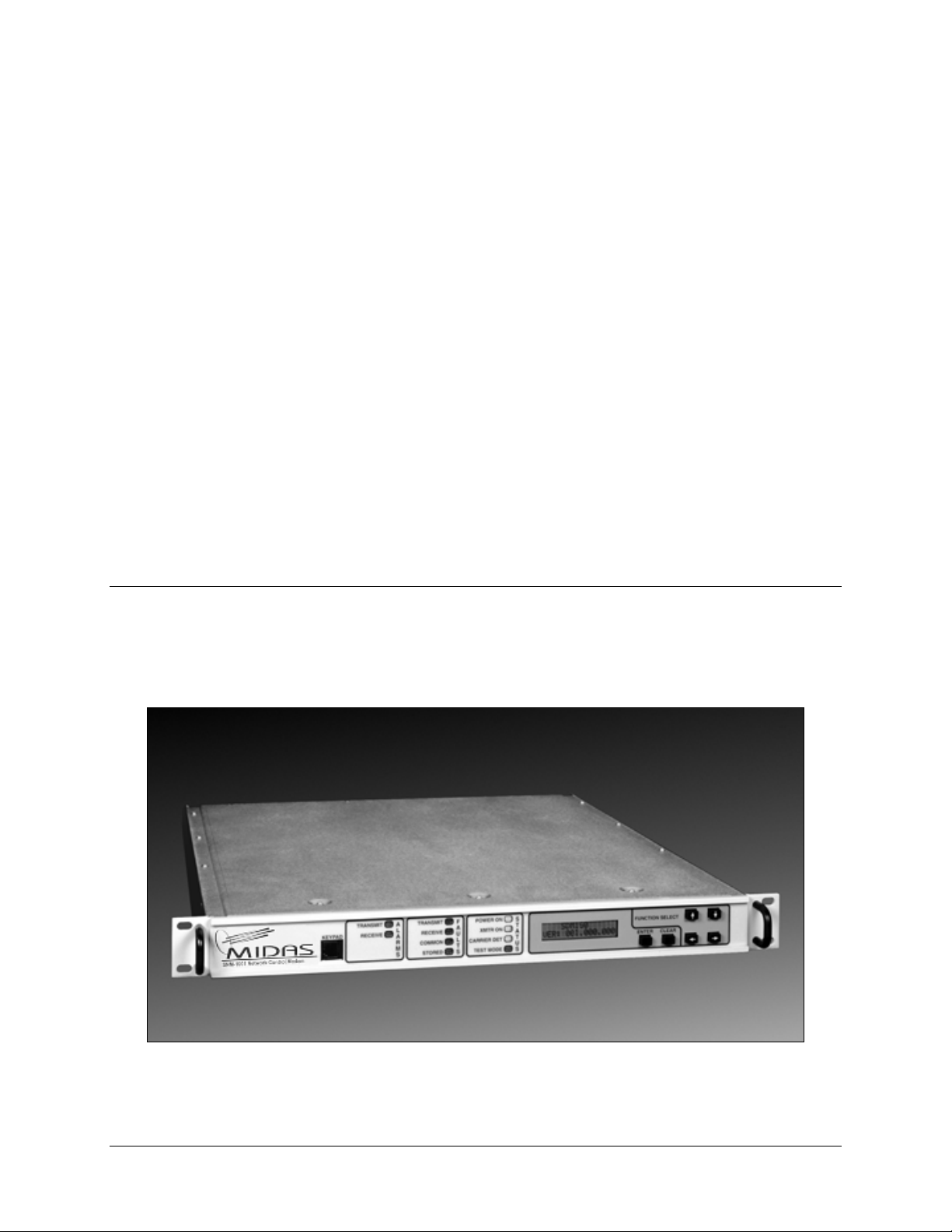
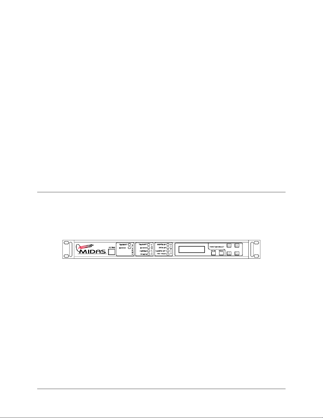
The SNM-1001 Network Control Modem (Figure 1-1) is a fully integrated, digital
satellite network channel modem.
Chapter 1.
INTRODUCTION
1
Figure 1-1. SNM-1001 Network Control Modem
Rev. 1 1–1
Page 13

Introduction SNM-1001 Network Control Modem
Using digital signal processing techniques, it functions as the network control channel
modem for Comtech EFData’s Bandwidth-on-Demand (BOD) Multimedia Integrated
Digital Access System (MIDAS).
Features of the SNM-1001 include the following:
• Fully integrated master control mode functionality
• 19.2 kbit/s, QPSK, 1/2 rate burst mode demodulator
• 19.2 kbit/s, QPSK, 1/2 rate continuous mode modulator
• Operational parameters stored in EEPROM
• 50/180 MHz operation
1.2 Mode of Operation
The SNM-1001 is an integral component of the MIDAS Network Management System
(NMS), providing the control channel communication path between the NMS and the
remote nodes.
The NMS transmits commands to the remote nodes through the SNM-1001, using a
continuous, TDM, outbound carrier. The remote nodes send requests and status messages
to the NMS using the slotted ALOHA burst inbound channel. This inbound channel
technology allows multiple remote nodes to share a single inbound carrier.
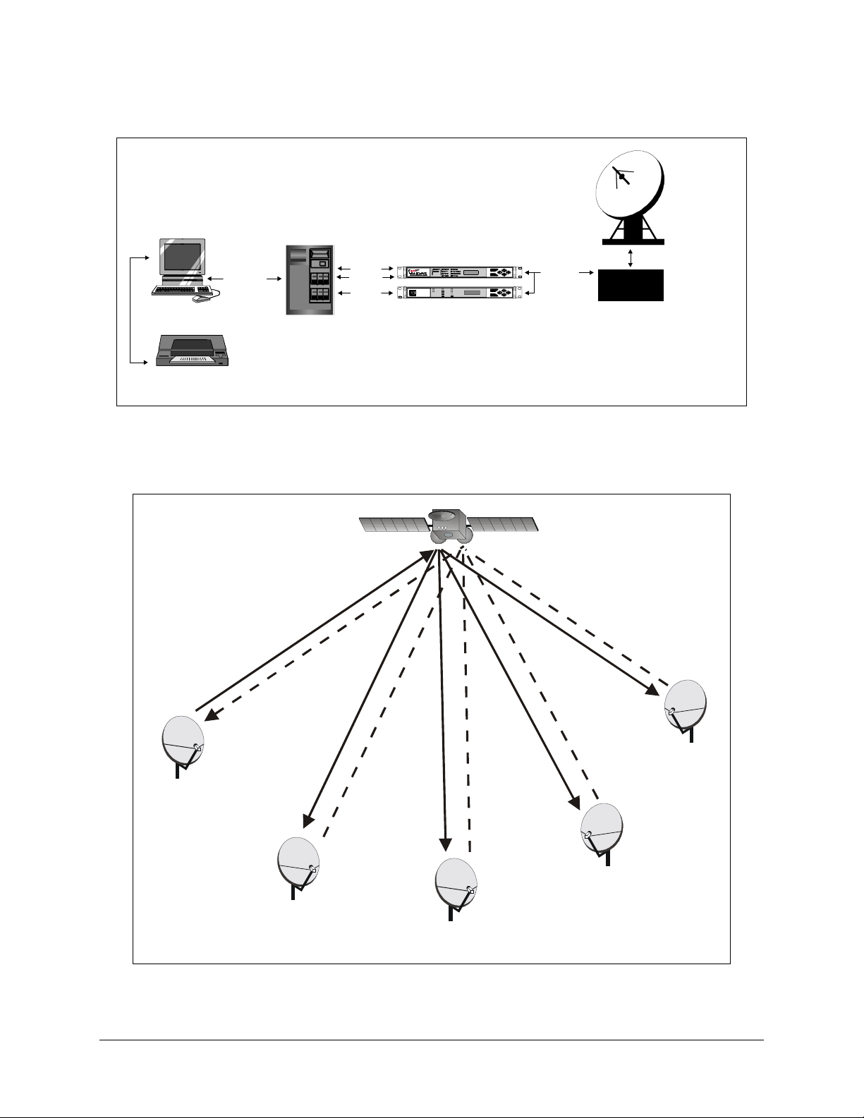
A typical NMS configuration is shown in Figure 1-2. A typical network control channel
configuration is shown in Figure 1-3.
1–2 Rev. 1
Page 14
SNM-1001 Network Control Modem Introduction
)
NETWORK CONTROL MODEM
OPERATOR
WORKSTATION
OPTIONAL PRINTER
(USER SUPPLIED)
ETHERNET
NMS
CONTROLLER
EIA-422
EIA-232
EIA-232
(SNM-1001)
SNM -1001 Network Control Modem
TRANSMIT
TRAN SMIT
A
F
L
A
RECEIVE
RECEIVE
SDT -1200
A
U
R
L
COMMON
SATELLITE TERMIN AL
M
T
S
S
STORED
LinkSync MODEM
(SNM-1002)
ENTER
CLEAR
POWER ON
ENTER
TRANSMITTER ON
CARRIE R DET ECT
CLEAR
TEST MODE
TM
IF
(50-180 MHz)
RFT
Figure 1-2. Typical NMS Configuration
BURST
CONTINUOUS
NMS SITE
(SNM-1001)
TDMA INBOUND
TDN OUTBOUND
REMOTE 3
(SNM-1010)
REMOTE 1
(SNM-1000)
REMOTE 2
(SNM-1000)
Figure 1-3. Typical Network Control Channel Configuration
REMOTE 4
(SNT-1020
Rev. 1 1–3
Page 15
Introduction SNM-1001 Network Control Modem
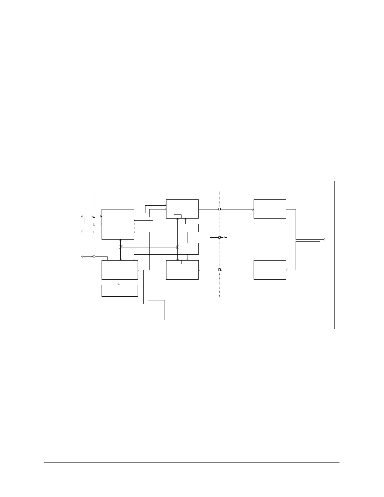
1.2.1 Description
The SNM-1001 is a complete, self-contained unit in a standard 1 Unit (1U) 19”
(48.26 cm) rack-mountable enclosure weighing approximately 10 lbs. (8.63 kg.)
All Monitor and Control (M&C) functions and indicators for operation of the modem, as
well as the display Printed Circuit Board (PCB), are located on the front panel.
The chassis contains the power supply; a fan is located on the rear panel.
A system block diagram is shown in Figure 1-4.
SNM-1001
CUSTOMER
DATA I/O
EXT.
CLOCK
ALARMS
FORM C
CONTACTS
REMOTE
SERIAL
INTERFACE
NETWORK
CONTROL MODEM
J8
J8
J7
J6
INTERFACE
DISPL AY AND
COMMAND BUS
M&C
KEYPAD
DATA
CLK
SCT
DATA
CLK
ENCODER/
MODULATOR
M&C
POWER
SUPPLY
M&C
DEMOD/
DECODER
IF OUTPUT
CP1
50 TO 90 MHz
100 TO 180 MHz
-5 TO -30 dBm
90 TO 264 VAC,
47 TO 63 Hz
IF INPUT
CP2
50 TO 90 MHz
100 TO 180 MHz
-30 TO -55 dBm
TRANSMIT
RF
EQUIPMENT
RECEIVE
RF
EQUIPMENT
ANTENNA
FRONT
PANEL
REMOTE
(OPT.)
Figure 1-4. SNM-1001 Block Diagram
1.3 Options
The following option is available for the SNM-1001:
• ± 48 VDC power
1–4 Rev. 1
Page 16

SNM-1001 Network Control Modem Introduction
1.4 Specifications
Table 1-1 and Table 1-2 list the operating specifications of the modem in Burst mode and
Continuous mode, respectively.
Table 1-1. Burst Mode Specifications
General Specifications
Operating Frequenc y Range 50 to 180 MHz, synthesiz e d in 100 H z st e ps
Type of D e modulation QPSK
Operating Channel Spacing Less than 0.5 dB degradation operating with 2 adjacent-like
channels, each 10 dB higher at 1.3 times the symbol rate, or
a minimum of 1.2 times the speci f i e d ac quis ition ra ng e
Bit Error Rate See Table 1-3
Digital Interfac e EIA-422/449 on 37-pin D
Digital Data Rate:
QPSK, 1/2 Rate 19.2 kbit/s
Doppler Buffer N/A
Forward Error Correc tion Convolutional encoding with s oft decision, K=7 Viterbi
decoding.
Data Descrambling Selectable or none, 215-1, synchronous
Prime Power 90 to 264 VAC auto select, 47 to 63 H z , 50W maxim um,
fused at 2A
Size 1.75” H x 19.0” W x 20.1” D ( 4.44 H x 48.26 W x 51.0 D
cm) (see Figure 2-2)
Operating Temperature
Storage Temperature
Humidity 0 to 95% noncondensing
Diagnostic Feature s IF Loopback
Additional Demodulator Specifications
Input Power (Desired Ca r rie r ) -30 to -55 dBm (com posite )
Input Impedance 75Ω standard
Input Return Loss 20 dB
Carrier Acquis ition Ra ng e
Clock Acquisition Ra ng e
Acquisition Tim e < 30 ms
Directed Sweep N/A
0° to 55°C (32° to 131° F)
-55° to +70°C (-131° to 158° F)
RF Loopback
Baseband Loopback (bi-directional, elect ric a l)
Fault Monitoring
Bit Error Rate Monitoring
Remote Control via Serial Port
+30 dB power within 2 MH z from desired c a rr ie r
+40 dB power outside of 2 MHz from de s ir ed c a r ri e r
– 5 dBm maximum composite
4 kHz minim um
±
100 PPM
±
Rev. 1 1–5
Page 17

Introduction SNM-1001 Network Control Modem
Table 1-2. Continuous Mode Specifications
General Specifications
Operating Frequenc y Range 50 to 180 MHz, synthesiz e d in 100 H z st e ps
Type of Modula tion QPSK
Operating Channel Spacing Less than 0.5 dB degradation operating with 2 adjacent-like
channels, each 10 dB higher at 1.3 times the symbol rate, or a
minimum of 1.2 times the spec ified acquisition range
Phase Noise In accordance with IESS-308
Digital Interface
(Field Changeable Plug-in Modules )
One Interface per Module)
Digital Data Rates:
QPSK, 1/2 Rate 19.2 kbit/s
Doppler Buffer Program mable from 64 to 65536 bits , or from 1 to 50 ms
Forward Error Correc tion Convolutional encoding with s oft decision K=7 Viterbi
Data Scrambling CCITT V.35
Prime Power 90 to 264 VAC auto select, 47 to 63 H z , 50W maxim um,
Size 1.75” H x 19.0” W x 20.1” D ( 4.44 H x 48.26 W x 51.0 D
Operating Temperature
Storage Temperature
Humidity 0 to 95% noncondensing
Diagnostic Feature s IF Loopback
Additional Modulator Specifications
Output Power -5 to -30 dBm, adjustable in 0.1 dB st e ps
Output Spurious and Harmonic s -55 dBc in 4 kHz BW in- ba nd (50 to 180 MH z )
Output Impedance 75Ω standard
Output Return Loss 20 dB
Output Frequency Stability
Data Clock Source Internal or external
Internal Data Clock Stability
EIA-422/449 on 37-pin D
total depth
decoding, Sequential decoding
fused at 2A
cm) (see Figure 2-2)
0° to 55°C (32° to 131° F)
-55° to +70°C (-131° to 158° F)
RF Loopback
Baseband Loopback (bi-directional, elect ric a l)
Fault Monitoring
Bit Error Rate Monitoring
Remote Control via Serial Port
-55 dBc in 4 kHz BW out- of-band (0 to 500 MHz)
10 PPM
±
External clock
10 PPM
±
100 PPM and < 5% jitter
±
1–6 Rev. 1
Page 18

SNM-1001 Network Control Modem Introduction
Remote Control Specifications
Serial Interface EIA-232, baud rate is19,200 bit/s.
Signals Controlled/Monitored Transmit Frequency
Receive Frequency
Transmit Power
Transmitter ON/OFF
IF Loopback
RF Loopback
Baseband Loopba c k
Scrambler ON/OFF
Descrambler ON/OFF
Sweep Center
Filter Mask
Raw Error Rate
Corrected Bit Error Rate
Receive E
b/N0
TX Clock Internal/External
RX Clock Normal/Invert
Receive Signal Level
Receive Carrier Detect
Power Supply Voltage s
Fault Status
Stored Fault Status
Configuration Retention Will maintain current config uration for at least one ye ar without
power
Addressing Programmable to 1 of 255 possibilitie s
Address 0 res e rved for global addr e s s ing
The Bit Energy-to-Noise Ratio (Eb/N0) required to achieve 10-6 to 10-9 bit error rate in
Burst mode is listed in Table 1-3.
Table 1-3. Burst Mode BER Specifications
Eb/N
0
6 dB 6.4
8 dB 1.1
BER PER ACQ
-4
-4
6.3
9.1
-2
-3
93%
99%
Notes:
1. Burst mode performance is measured with a 100 byte packet.
2. BER values are measured with a packet long enough to allow 100 errors.
Rev. 1 1–7
Page 19
Introduction SNM-1001 Network Control Modem
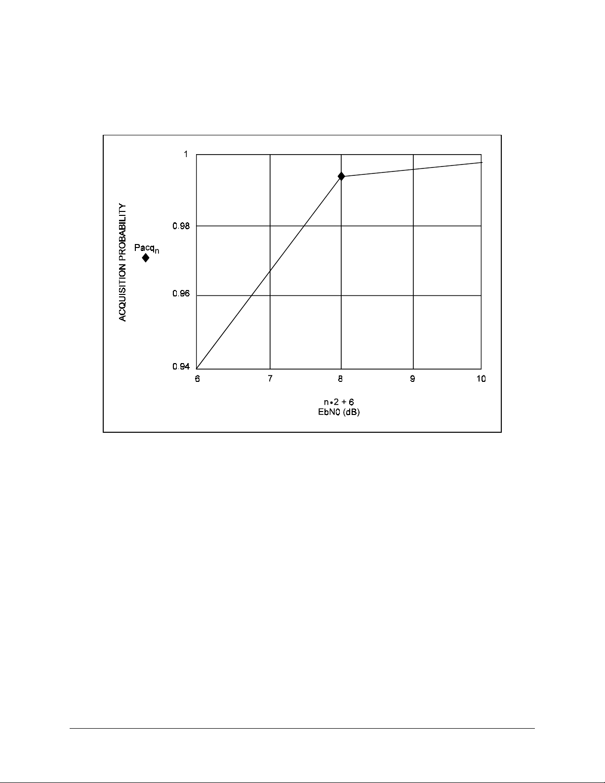
Acquisition performance of the modem is shown in Figure 1-5.
Figure 1-5. SNM-1001 Acquisition Performance
1–8 Rev. 1
Page 20
SNM-1001 Network Control Modem Introduction
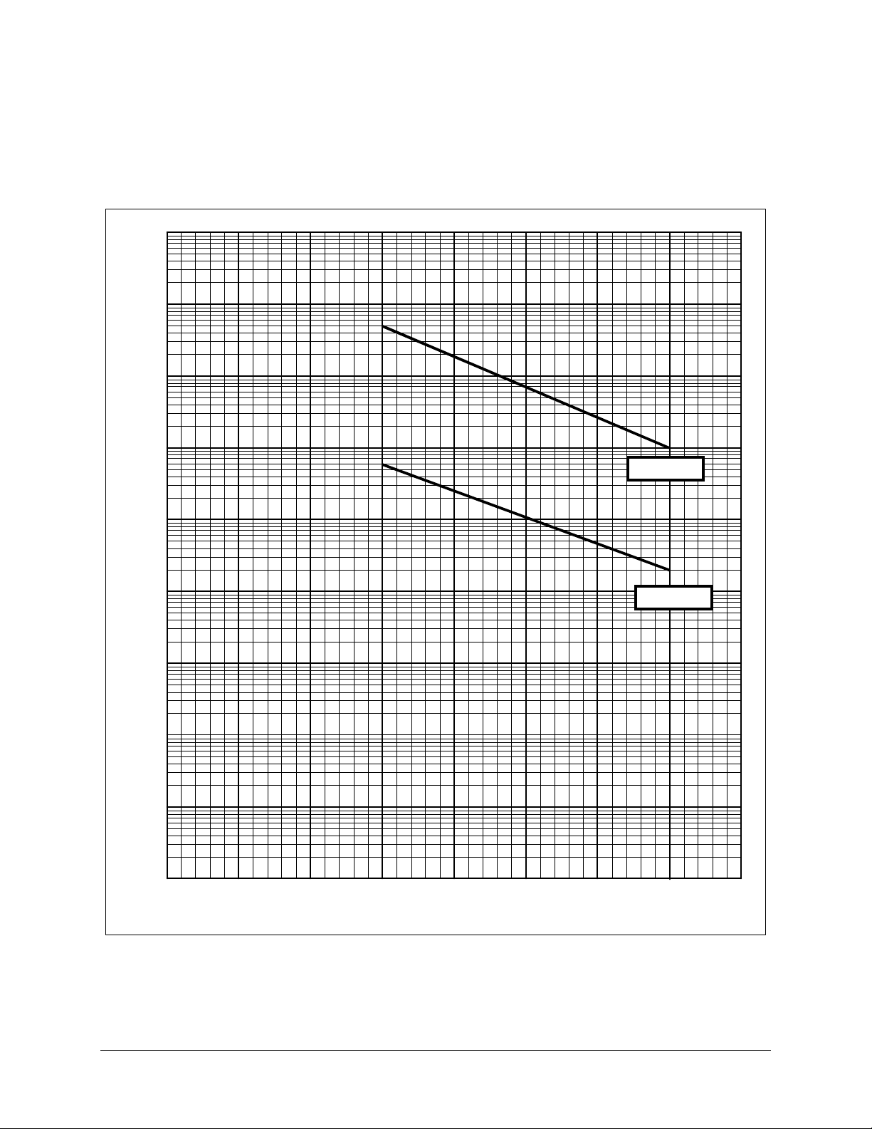
The Bit Error Rate (BER) performance of the modem in Burst mode is shown in
Figure 1-6.
1
-1
10
-2
10
-3
10
BER
-4
10
BER
-5
10
-6
10
-7
10
-8
10
3.0 4.0 5.0 6.0
BER
7.0 8.0 9.0 10.0 11.0
E
(dB)
b/N0
Figure 1-6. SNM-1001 Bit Error Rate Performance (Burst Mode)
Rev. 1 1–9
Page 21

Introduction SNM-1001 Network Control Modem
This page is intentionally left blank.
1–10 Rev. 1
Page 22

This chapter contains the following information:
• Unpacking
• Installation
• System options
• External connections
2.1 Unpacking
The modem and manual are packaged in a pre-formed, reusable cardboard carton
containing foam spacing for maximum shipping protection.
Chapter 2.
INSTALLATION
2
The circuit cards are contained in the modem chassis.
Do not use any cutting tool that will extend more than 1” (2.54cm) into the
container and cause damage to the modem.
CAUTION
To remove the modem:
1. Cut the tape at the top of the carton where it is indicated OPEN THIS END.
2. Lift out the cardboard/foam spacer covering the modem.
3. Remove the modem, manual, and power cord from carton.
Rev. 1 2–1
Page 23

Installation SNM-1001 Network Control Modem
4. Save the packing material for reshipment purposes.
5. Inspect the equipment for damage incurred during shipment.
6. Check the equipment against the packing list to ensure that the shipment is
complete.
2.2 System Installation
To install the modem:
1. Mount the modem chassis in the assigned position in the equipment rack. Refer
to
Figure 2-1 for a typical rack elevation for an M:N system. For a custom rack
installation, refer to the chassis dimensional drawing in Figure 2-2.
Connect the cables to the appropriate locations on the rear panel. Section 2.3
contains a description of connector pinouts, placements, and functions.
Before turning on the power switch, read and become familiar with Chapter 3.
Verify that all jumper settings are correctly set for remote operation. Jumper
settings are listed in Table 4-1.
Turn on the power switch, located on the rear panel.
Check for proper TX output signal level and spectrum.
Check for proper RX input signal level and spectrum.
If there is any problem with the installation, refer to Chapter 5 for instructions on
how to troubleshoot the system.
2–2 Rev. 1
Page 24
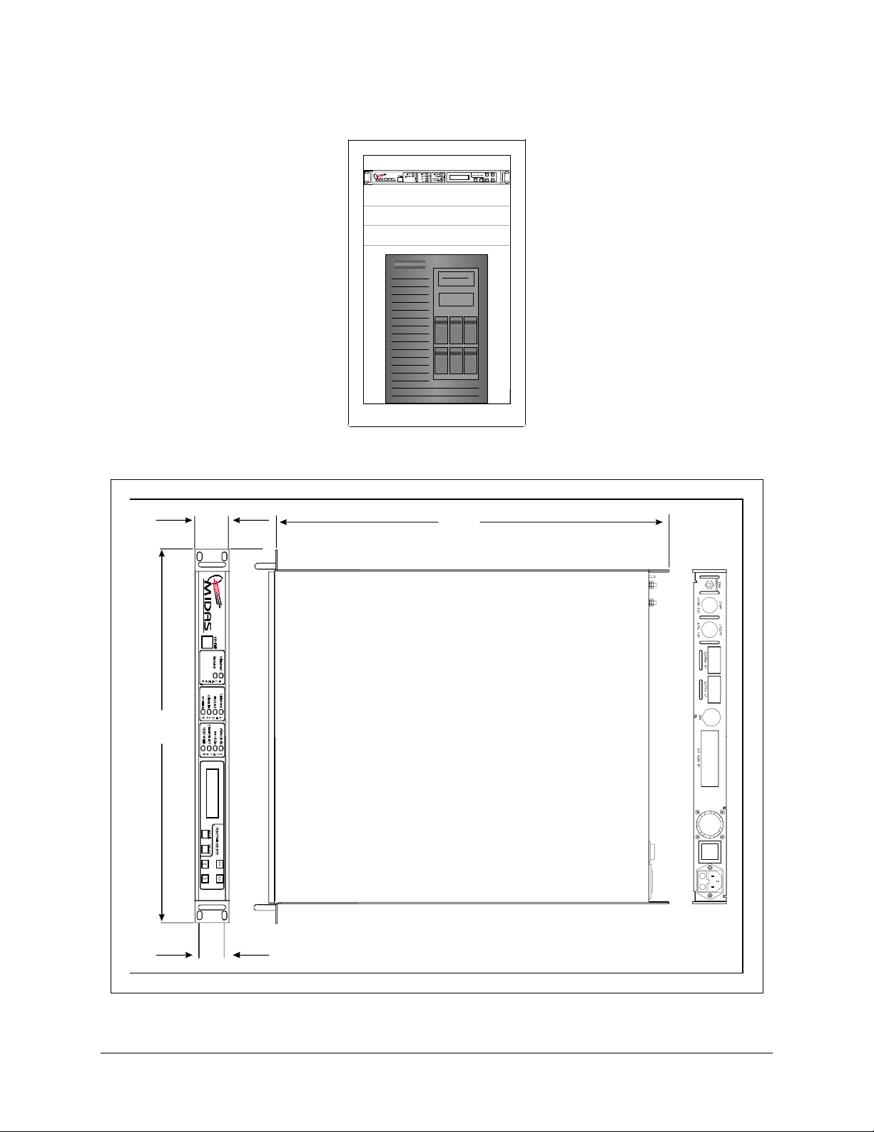
SNM-1001 Network Control Modem Installation
SNM -1001 Network
Figure 2-1. Typical Rack Elevation
19.0
(48.26)
1.75
(4.5)
S N M -1001 N etw ork C ontrol M odem
20.10
(51.0)
1.25
(3.17)
Figure 2-2. Chassis Dimensional Drawing
Rev. 1 2–3
Page 25
Installation SNM-1001 Network Control Modem
2.3 External Modem Connectors
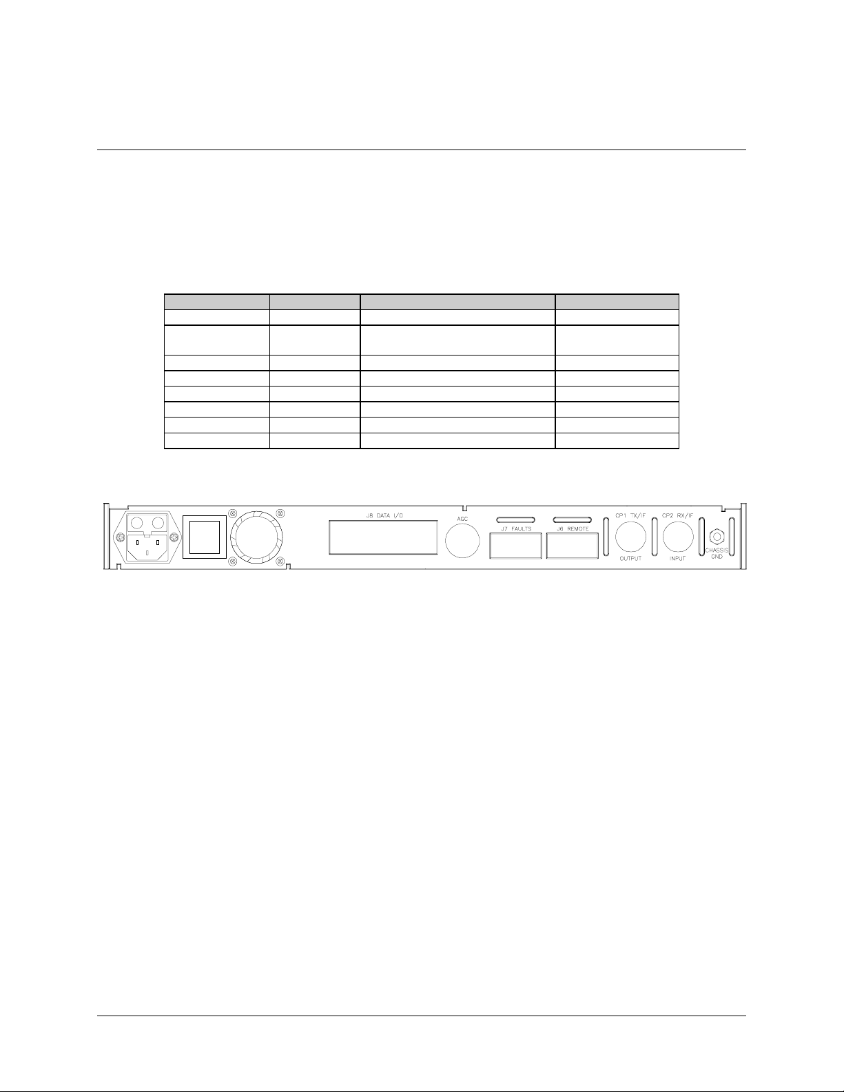
Connections between the modem and other equipment are made through five connectors.
These connectors are listed in Table 2-1 and their locations are shown in Figure 2-3. The
use of each connector is described in the following paragraphs.
Table 2-1. Rear Panel Connectors
Name Ref. Design Function Connector Type
AC POWER None AC Power Input Standard
DATA I/O J8 DATA Input/Output ( I/O )
EIA-422/449
AGC None AGC Test Point Test Point
FAULTS J7 FORM-C Fault Relay Contacts 9-pin Female D
REMOTE J6 Remote Interf a ce 9-pin Female D
TX IF OUTPUT CP1 TX IF Output BNC
RX IF INPUT CP2 RX IF Input BNC
CHASSIS GND None Chassis Ground #10-32 Stud
Various
37-pin D
Figure 2-3. SNM-1001 Rear Panel View
2.3.1 DATA I/O Interface (J8)
The DATA I/O interface connector is used to interface data input and output signals to
and from the modem. J8 connects to the customer terrestrial equipment directly, or
through a protection switch. The modem operates with a single interface configuration.
The DATA I/O interface is EIA-422/449.
2–4 Rev. 1
Page 26

SNM-1001 Network Control Modem Installation
2.3.1.1 EIA-422/449 Interface Connector Pinouts
The EIA-422/449 interface is provided on a 37-pin female D connector accessible on the
rear panel of the modem. Screw locks are provided for mechanical security of the mating
connector.
Signal Function Name Pin #
Send Data SD-A
SD-B
Send Timing ST-A
ST-B
Receive Data RD-A
RD-B
Request to Send EIA-A
EIA-B
Receiver Timing RT-A
RT-B
Clear to Send CS-A
CS-B
Data Mode DM-A
DM-B
Receiver Ready RR-A
RR-B
Terminal Timing TT-A
TT-B
Master Clock (input) MC-A
MC-B
Demod Fault – 21
Mod Fault – 3
Signal Ground SG 1, 19, 20, 37
(See Note)
(See Note)
(See Note)
(See Note)
4
22
5
23
6
24
7
25
8
26
9
27
11
29
13
31
17
35
16
34
Note:
The EIA and CS lines are jumpered together on the demod/M&C card
(AS/4973-2), since the modem does not support polled operation.
Rev. 1 2–5
Page 27

Installation SNM-1001 Network Control Modem
2.3.2 Remote (J6)
The remote connector allows the user to interface the Monitor and Control (M&C)
functions with a remote location. This interface is EIA-232-C. For further discussion on
the remote interface, refer to Chapter 4.
The remote interface is provided on a 9-pin female D connector. Screw locks are
provided for mechanical security of the mating connector.
The remote connector is a Data Circuit Terminating Equipment (DCE) interface.
There are jumpers that must be set on the demodulator board to select the EIA-232-C
remote interface. Refer to Chapter 4 for their location and configuration information.
EIA-232-C
4-Wire and 2-Wire Mode
Pin # Name
1
2RD (RX)
3TD (TX)
4
5GND
6DSR
7RTS
8CTS
9
2–6 Rev. 1
Page 28

SNM-1001 Network Control Modem Installation
2.3.3 Faults (J7)
The fault connector on the modem is used to provide FORM-C contact closures for the
purpose of fault reporting. There are three FORM-C summary fault contacts:
• Modulator
• Demodulator
• Common equipment
To obtain a system summary fault, connect all FORM-C contacts in parallel.
The fault interface is provided on a 9-pin female D connector. Screw locks are provided
for mechanical security of the mating connector. The pinout of the connector is as
follows:
Pin # Name Function
1 NO C ommon equipment is not f a ulte d
2COM
3 NC Common equipment is faulted
4 NO Modula tor is not faulted
5COM
6 NC Modulator is faulted
7 NO D e modulator is not faulted
8COM
9 NC Demodulator is faulted
Note:
A connection between the common (COM) and normally open (NO) contacts
indicates no fault.
2.3.4 TX IF Output (CP1)
CP1 is the transmit IF connector. The output impedance is 75Ω. The output power level
is -5 to -30 dBm, in 0.1 dB steps.
In normal operation, the output will be a QPSK modulated result of the DATA I/O
connector, between 50 and 180 MHz.
Rev. 1 2–7
Page 29

Installation SNM-1001 Network Control Modem
2.3.5 RX IF Input (CP2)
CP2 is the receive IF connector. The input impedance is 50Ω (75Ω optional).
In normal operation, the desired carrier signal level should read between -30 and 55 dBm.
Signals between 50 and 180 MHz are selected and demodulated to produce clock and
data at the DATA I/O connector.
2.3.6 AC Power
The AC power is supplied to the modem by a standard, detachable, non-locking, 3-prong
power cord. Normal input voltage is 90 to 264 VAC, 47 to 63 Hz. The modem will
automatically switch between ranges. Maximum power consumption is less than 40W.
2.3.7 DC Power
DC power is available as an option. The DC power is supplied to the modem by a 3
position terminal block. Normal input voltage is ± 48 VDC,
consumption is less than 40W.
2.3.8 Chassis GND
A #10-32 stud is available on the rear panel for the purpose of connecting a common
chassis ground between all of the equipment.
Note:
The safety ground is provided through the AC power connector.
2.3.9 AGC Test Point
The Automatic Gain Control (AGC) test point is a BNC connector on the back of the
modem chassis. This feature allows the user to monitor the AGC.
10%. Maximum power
±
2–8 Rev. 1
Page 30
This chapter describes the front panel operation and clocking options of the modem.
3.1 Front Panel
The front panel of the modem (Figure 3-1) is locked out. It displays SNM-1001. The
NMS sets all values.
S N M -1001 N etw o rk C o n tro l M o d em
Chapter 3.
OPERATION
3
Figure 3-1. SNM-1001 Front Panel View
Rev. 1 3–1
Page 31

Operation SNM-1001 Network Control Modem
3.1.1 LED Indicator
General modem status and summary fault information are indicated by 10 LEDs on the
front panel. The indicators are defined in the following tables.
Faults
Name LED Description
Transmit Red Indicates that a fault condition e x ists in the transmit chain.
Receive Red Indicates that a fault condition exists in the receive chain.
Common Red Indicates that a common equipment fault condition exists.
Stored Yellow Indicates that a fault has been logged and stored. The fault may or
may not be ac tiv e .
Status
Name LED Description
Power ON Green Indicates that power is applied to the modem.
Transmitter ON Green Indicates that the transmitter is currently ON. This indicator ref le cts
the actual condition of the tra nsmitter, as opposed to the
programm e d c ondition.
Carrier Detect Green Indicates that the decoder is locked.
Test Mode Yellow Flashes when the modem is in a test conf ig uration.
Alarms
Name LED Description
Transmit Yellow Indic a te s tha t a transmit function is in an alarm condition.
Receive Yellow Indicates that a receive function is in an alarm condition.
3.1.2 Front Panel Keypad Option
This feature is a future option which will allow the user to plug in a hand-held keypad,
and will allow access to all programming capabilities.
3.2 Clocking Options
The clocking is addressed through the NMS.
3–2 Rev. 1
Page 32

This chapter describes the theory of operation for the various PCBs in the modem.
4.1 Modulator
The modem modulator creates a QPSK modulated carrier within the 50 to 180 MHz
range from the digital data stream provided by the interface section.
The following subsections make up the modulator:
• Scrambler
• Convolutional encoder
• I/Q Nyquist filters
• Modulator
• Output amplifier
• RF synthesizer
• SCT synthesizer
Chapter 4.
THEORY OF OPERATION
4
Modulator jumper settings are shown in Table 4-1 .
A block diagram of the modulator is shown in Figure 4-1.
Rev. 1 4–1
Page 33

Theory of Operation SNM-1001 Network Control Modem
Table 4-1. M&C Jumper Settings (AS/4973)
ConfigurationJumper Position
Redundant Non-Redundant
JP10 1 to 2 Closed Open
3 to 4 Closed Open
5 to 6 Open Closed
7 to 8 Open Closed
JP 22 5 to 6 Open Closed
JP 2 1 to 2 Closed Open
2 to 3 Open Closed
JP 3 1 to 2 Closed Open
2 to 3 Open Closed
JP 11 1 to 2 CTS shorted to TX FPGA CTS shorted to TX FPGA
JP 6, JP7 2 to 3 Closed Closed
JP 18 1 to 2 Closed Closed
JP 21 2 to 3 Off Off
M&C
COMMAND
BUS
TX_DATA
TX_CLOCK
0
VCO
EXT.
RX SAT CLK
MICROPROCESSOR
MPC
SCRAMBLERS
PREAMBLE
GENERATOR
POSTAMBLE
IF FILTER
CLOCK
MPC
90
DDS
IMPC
MPC
MPC
CONVOLUTIONAL
ENCODERS
I
Q
REF
OSC
RF
SYNTH
VECTOR
ROTATION
I
Q
Figure 4-1. Modulator Block Diagram
VARIABLE
ATTENUATOR
MPC
ATTENUATOR
DIGITAL
NYQUIST
DIGITAL
NYQUIST
OUTPUT SWITCH
RF SWITCH
DAC
DAC
IF
50 to 180 MHz
-5 to-30 dBm
ALIAS
FILTER
ALIAS
FILTER
OUTPUT
IF LOOPBACK
SCT
4–2 Rev. 1
Page 34

SNM-1001 Network Control Modem Theory of Operation
4.1.1 Specifications
Modulation Type QPSK
Digital Data Rate:
QPSK, 1/2 Rate 19.2 kbit/s
Test Modes Carrier null and quadrature (dua l a nd offset) CW
Frequency Ra ng e 50 to 180 MHz
Frequency Selec t Method Synthesized
Frequency Step Size 100 Hz
Frequency Stability (RF)
Frequency Stability (SCT)
Phase Error 2.5° maximum
Filtering Type Nyquist, pre-equa lize d
Spectral Occupancy
Spurious and Harmonic s -55 dBc, 0 to 500 MHz
Output Power Level Ra ng e
Output Stability
Output Power Adjustm e nt 0.5 dB step size
Output Impedance
Output Return Loss 20 dB minim um
Scrambling CCITT V.35
FEC Encoding Convolutional K=7 1/2 Rate Viterbi
Decoding Soft-decision Viterbi
Reported Faults AGC level fault
10 PPM internal oscillator
±
10 PPM internal oscillator
±
Spectral density is -30 dB , ± 0.75 symbol rate
-5 to -30 dBm, ± 0.5 dB
0.5 dB
±
75
Ω
Rate 1/2
Synthesizer f a ult
I channel filter activity
Q channel filter activity
Clock activity f a ult
4.1.2 Theory of Operation
The modulator is composed of two basic sections: the baseband processing section and
the RF section. The modem M&C controls all programmable functions in both sections.
Data to be transmitted will come from the interface card via the demodulator. The format
is EIA-422, and includes a clock that is synchronous with the data. The data signal at this
point is clean and free of jitter. The data signal goes to the scrambler, which provides
energy dispersal. It then goes to a differential encoder. The data signal passes to the
Viterbi K = 7 convolutional encoder.
The output of the encoder generates two separate data streams to drive the I&Q channels
of the modulator. If selected from the front panel menu, one channel can be inverted,
causing a spectral inversion.
Rev. 1 4–3
Page 35

Theory of Operation SNM-1001 Network Control Modem
From the encoder, the data signal passes through a set of variable-rate digital Nyquist
filters. The filter set is for Comtech EFData Closed Network. There are activity detectors
on both the I&Q channel Nyquist filters.
The digital Nyquist filters are followed by Digital to Analog (D/A) converters and
reconstruction filters. These filters provide proper spectral shaping and equalization. The
filters are under control of the M&C. The symbol rate is 19.2 ks/s.
The I&Q filtered data signals are applied to the RF modulator, which converts them to a
modulated carrier. The spectral shape will be identical to that of the input data streams,
but double-sided about the carrier frequency.
The RF synthesizer provides the proper frequencies to convert the modulator IF to the
desired output frequency in the 50 to 180 MHz range. The synthesizer has multiple
loops, and incorporates a DDS chip to accommodate 100 Hz steps over a range of 130
MHz. The RF section has a frequency stability of
±
1 x 10⁻⁵.
The signal from the power combiner is sent to the output amplifier, which amplifies the
low level signal from the modulator section to the proper level for output from the
module. The amplifier contains circuitry that provides programmable control of the
output level over a range of -5.0 to -30.0 dBm, in 0.1 dB steps. Power leveling is
provided at
±
1.0 dB to maintain the stability of the output level over time and
temperature.
Fault information from the modulator is sent to the M&C, and includes:
• Synthesizers out-of-lock
• RF output leveled
• Input data clock activity
• I channel digital filter activity
• Q channel digital filter activity
4–4 Rev. 1
Page 36

SNM-1001 Network Control Modem Theory of Operation
4.2 Demodulator
The modem demodulator converts a QPSK modulated signal of 50 to 180 MHz to a
demodulated baseband data stream. The demodulator then performs error correction on
the data stream, using a Viterbi decoding algorithm.
A block diagram of the demodulator is shown in Figure 4-2.
Demodulator jumper settings for selecting ROM size are listed in Table 4-1.
RF
IF INPUT
50 TO 180 MHz
-55 TO -30 dBm
IF
LOOPBACK
AGC
RXDATA
RXCLOCK
RR
MICRO-
PROCESSOR
MPC
SYNCHRONOUS
DESCRAMBLER
IF FILTER
RF
SYNTH
MPC
MPC
I
Q
LOOP
LOOP
DIGITAL
NYQUIST
DIGITAL
NYQUIST
ALIAS
FILTER
ALIAS
FILTER
0
90
VCO
DDS
VITERBI
MPC
DDS
A/D
A/D
BB
SOFT DECISION
MAPPING
UNIQUE WORD
DETECTOR
DIGITAL
COSTAS
DELAY
DIGITAL
CLOCK
Figure 4-2. Demodulator Block Diagram Burst Mode
Rev. 1 4–5
Page 37

Theory of Operation SNM-1001 Network Control Modem
4.2.1 Specifications
Digital Data Rate:
QPSK, 1/2 Rate 19.2 kbit/s
Symbol Rate 19.2 ks/s
IF Frequency 50 to 180 MHz, in 100 Hz steps
Input Level -30 to -55 dBm
Decoding Ty pe 1/2
Filter Mask Closed network
Scrambler Types 215-1 Synchronous
Modulation Types QPSK
4.2.2 Theory of Operation
The demodulator card functions as an advanced, fully digital, coherent phase-lock
receiver, and a Viterbi or Sequential decoder.
The following subsections make up the demodulator:
• RF synthesizer
• IF amplifier
• Quadrature demodulator
• Identical anti-aliasing filters
• D/A converters
• Digital Nyquist filters
• Costas loop
• Clock loop
• Automatic Gain Control (AGC)
• Automatic Offset Control (AOC)
• Unique word detector
• Ambiguity resolver
• Soft-decision decoder
• Synchronous descrambler
• End of message detector
The modulated signal enters the RF module, where it is converted from an IF signal at 50
to 180 MHz to I&Q baseband channels. The synthesizer has multiple loops, and
incorporates a DDS chip to accommodate 100 Hz steps over a range of 130 MHz. The
RF section has a frequency stability of
±
1 x 10⁻⁵.
The two channels are then passed through identical anti-aliasing filters, D/A converters,
and digital Nyquist filters.
4–6 Rev. 1
Page 38

SNM-1001 Network Control Modem Theory of Operation
The result is a filtered, digital representation of the received signal. A Costas loop
maintains the phase lock during the message. A phase-lock loop maintains the data clock.
The soft-decision mapper converts the I&Q samples to soft-decision values. The
soft-decision values are then fed to the Viterbi decoder, where error detection and
correction are performed.
The I&Q channels are also used to calculate the AGC and AOC voltages. The AGC and
AOC are fed back to the RF module.
Finally, the data from the output of the Viterbi decoder is descrambled with a 2
15
-1
synchronous descrambler, and routed to the interface card. There also is a summary fault
relay that provides a FORM C output located on the demodulator board.
The data clock phase can be selected from the Interface Utility menu.
Using Digital Signal Processing (DSP) techniques, the demodulator looks for carrier
power in an 8 kHz bandwidth. When a carrier is detected, the DSP calculates the offset
from the nominal frequency. The DSP then zeros out the offset. This occurs during the
CW portion of the preamble sequence. During the second part of the preamble sequence,
the clock phase is recovered. When the unique word is detected, the Demod determines
the ambiguity of the received signal. It then corrects the ambiguity, if necessary, and
starts feeding data to the Viterbi decoder. A delay generator determines when the first bit
of the data packet comes out of the Viterbi decoder, and initiates the synchronous load of
15
the 2
-1 synchronous descrambler. After the descrambler starts the lock, the RR lines are
set to true, denoting that valid data is being received. The demodulator, when locked,
continually monitors the incoming data for the end-of-message marker. When the
end-of-message marker is detected, a delay generator determines when the remaining
data has been flushed out of the modem, and the Lock and RR line is set to false.
Note:
The data packet must not be less than 48 bits of data. There is no maximum length
for the data packet.
4.2.3 Viterbi Decoding Theory
The Viterbi decoder is used in open-network applications, typically in Intelsat Business
Service (IBS) or Intermediate Data Rate (IDR) communication systems. The Viterbi
decoder operates in conjunction with the convolutional encoder in the transmit modem.
The Viterbi decoder and convolutional encoder correct the transmission channel errors in
the received data stream.
Figure 4-3 is a block diagram of the Viterbi decoder.
Rev. 1 4–7
Page 39

Theory of Operation SNM-1001 Network Control Modem
MICRO-
COMPUTER
BUS
I CHANNEL
Q CHANNEL
MICROCOMPUTER
INTERFACE
COSTAS
PROCESSOR
FREQUENCY
LOCKED LOOP
CLOCK
RECOVERY
DEPUNCTURE
DECODER
AMBIGUITY
RESOLVERAND
VW DETECTOR
INPUT
BUFFER
VITERBI DECODER INCLUDES
CHANNEL BER DETECTION
DESCRAMBLER
LOCK
DETECT
DDS
RECEIVE
RECEIVE
CLOCK
AGC
CONTROL
IF
Figure 4-3. Viterbi Decoder Block Diagram
The Viterbi decoder processes 3-bit quantized R0 and R1 parallel code bits (symbols)
from the demodulator. The quantization is 3-bit soft-decision in sign/magnitude format.
This is a representation of the data transmitted, corrupted by additive white Gaussian
noise. The decoder uses the code symbols produced by the encoder to determine which
symbols have been corrupted by the transmission channel. The decoder corrects as many
corrupted symbols as possible.
The data signal passes through an ambiguity resolver, which compensates for the
potential 90° phase ambiguity inherent in a QPSK demodulator.
A set of branch metric values is then computed for each of the received symbol pairs.
The values are related to the probability that the received symbol pair was actually
transmitted as one of the four possible symbol pairs. The branch metrics are then
processed by the Add-Select-Compare (ASC) computer.
The ASC computer makes decisions about the most probable transmitted symbol stream
by processing the current branch metrics with the state metrics computed for the 64
previous decoder inputs. The results of the ASC computer are stored in memory called
“path memory.”
4–8 Rev. 1
Page 40

SNM-1001 Network Control Modem Theory of Operation
Path memory is 80 states in depth. The path with the maximum metric is designated as
the survivor path, and its data are used for output. The difference between the minimum
and the maximum path metrics is used as the means of determining synchronization of
the decoder.
The output data may then be descrambled and differentially decoded. Both of these
processes are optional, and may be selected locally or remotely. The data signal out of
the differential decoder is sent to the interface card for formatting and output.
The synchronization signal is used for lock detect, and is sent to the M&C. The raw BER
count is generated from re-encoding the decoded data and comparing it to a delayed
version of the input data. The count is then sent to the M&C for further processing.
4.3 Monitor and Control
The modem uses a sophisticated micro-controller module to perform the M&C functions
of the modem. This module is located on the demodulator board, and is referred to as the
“M&C.” The M&C monitors the modem and provides configuration updates to other
modules within the modem when necessary.
The modem configuration parameters are maintained in battery-backed RAM. The RAM
provides for total recovery after a power-down situation.
Extensive fault monitoring and status gathering are provided.
All modem functions are accessible through a remote communications interface.
4.3.1 Non-Volatile Memory
Non-volatile memory on the M&C module allows it to retain configuration information
without prime power for at least one year. Should the modem be powered down, the
following sequence is carried out when power is re-applied to the M&C:
1. The micro-controller checks the non-volatile memory RAM to see if valid data
has been retained. If valid data has been retained, the modem is reconfigured to
that information.
2. If non-volatile memory fails the valid data test, a default configuration from
ROM is loaded into the system.
Rev. 1 4–9
Page 41

Theory of Operation SNM-1001 Network Control Modem
4.3.2 Remote Interface Specification
Refer to Appendix A for the remote interface specification.
4.3.3 M&C Theory of Operation
The M&C module is built around the Intel 80C32 micro-controller, operating at
11.0592 MHz. The microsystem is designed to support up to 512 kbytes of read-only
code memory, and up to 32 kbytes of non-volatile random-access data memory.
4.3.4 Remote Interface Configuration
All modem functions can be remotely controlled and monitored via an EIA-232-C
communications link. The EIA-232-C interface is used to communicate with a single
modem.
For M&C jumper settings, refer to Table 4-1.
4.3.5 Modem Defaults
The M&C has default settings that are loaded into the modem at power-up. These default
settings are also loaded each time the modem has been hard reset. The following tables
list the defaults settings for each modem configuration parameter.
Modulator Defaults Demodulator Defaults
Data Rate A Data Rate A
TX Rate A 19.2 kbit/s, QPSK RX Rate A 19.2 kbit/s, QPSK
TX-IF Frequency 70 MHz RX-IF Frequency 70 MHz
TX-IF Output ON Descrambler ON
Mod Power Offse t 0 dB Differential Decoder OFF
TX Power Output -10 dBm Demodulator Type INTELSAT Open
Scrambler O N Decoder Type Viterbi, 1/2 Rate
Differentia l Encode r OFF IF Loopback OFF
Modulator Type INTELSAT O pe n RF Loopback OFF
Encoder Type Viterbi, 1/2 Rate BER Threshold None
CW Mode Normal (OFF)
Interface Defaults System Defaults
TX Clock Source T X T ER RE ST R IAL Time 12:00 AM
TX Clock Phase NORMAL Date 7/4/76
RX Clock Phase NORMAL Baud Rate 9600
Baseband Loopback OFF Parity Even
Defaults for Burst Mode
Address 1
Operation Mode Duplex
4–10 Rev. 1
Page 42

SNM-1001 Network Control Modem Theory of Operation
Defaults for Continuous Mode
Modulator Defaults Demodulator Defaults
Data Rate A Data Rate A
TX Rate 19.2 kbit/s, QPSK RX Rate 19.2 kbit/s, QPSK
TX-IF Frequency 70 MHz RX-IF Fr e que nc y 70 MHz
TX-IF Output ON Descrambler ON
Mod Power Offse t 0 dB Differential De c ode r ON
TX Power Output -10 dBm Demodulator Ty pe INTELSAT Ope n
Scrambler ON Decoder Type Viterbi
Differentia l Encode r ON IF Loopback OFF
Modulator Type INTELSAT Open RF Loopback OFF
Encoder Type Viterbi Sweep Center
Frequency
CW Mode Norm a l ( O FF) Sweep Range 70000 Hz
BER Threshold None
Interface Defaults System Defaults
TX Clock Source TX TERRESTRIAL Time 12:00 AM
Buffer Clock Sourc e RECEIVE SATELLI T E Date 7/4/76
TX Clock Phase AUTO Baud Ra te 9600
RX Clock Phase NORMAL Parity Even
Baseband Loopba c k OFF Addres s 1
Buffer Size BYPASS Operation Mode Duplex
0 Hz
Rev. 1 4–11
Page 43

Theory of Operation SNM-1001 Network Control Modem
4.4 Digital Interfaces
The modem interface module is a daughter card that plugs onto the demodulator board.
The module provides the interface for terrestrial data and overhead signals, and the fault
reporting output of the modem.
EIA-422/449 and EIA-232-C interfaces are available for input and output of terrestrial
data when the modem is in the Continuous mode. Both baseband and interface loopbacks
are provided. The terrestrial data rate is 19.2 kbit/s.
4.4.1 EIA-422/449 Interface
4.4.1.1 Functional Description
The EIA-422/449 digital interface provides the level translation, buffering, and
termination between the internal modem signals and the EIA-422/449 interface on the
rear panel.
Electrical characteristics of the EIA-422/449 interface signals are defined in EIA STD
EIA-422. Details of the mechanical interface are found in EIA STD EIA
-
449.
A functional diagram of the interface is shown in Figure 4-4.
The EIA-422/449 interface provides a Send Timing (ST) clock signal at the modem data
rate.
• In the Internal Clock mode, the data to be transmitted, Send Data (SD), must be
synchronized to ST.
• In the External Clock mode, the clock is accepted on the Terminal Timing (TT)
input to clock-in the data to be transmitted.
• In either Internal or External Clock mode, the phase relationship between the
clock and data is not important as long as it meets the EIA-422/449 jitter
specifications.
4–12 Rev. 1
Page 44

SNM-1001 Network Control Modem Theory of Operation
35
3
C
5
CS
C
3 5
8
S
S
33,3
0 81135,36
6
3
9
3
0
A clock phase correction circuit is provided which shifts the clock away from the data
transition times. The clock phasing is jumper selectable at JP1.
• When there is no jitter on the clock source, the Auto setting is used.
• The Normal setting is used when standard specifications on clock and data
relationships exist.
• The Invert mode is used when the incoming clock is inverted from the standard
clock and data relationship. Refer to Table 4-1 for jumper settings.
J1
P1
+TT
-
+
DF1
14
T
+12V
4
RT
1
-12V
RD
DM
INTF
INTF1
-
+
-
+M
-
MOD FAULT
+
+
+
-
+
-RT
+
-RD
+RR
-
+DM
-DM 11
4
27
T
1
2
Figure 4-4. EIA-422/449 Diagram
Data received by the modem is output on the Received Data (RD) lines, while the
recovered clock is output on the Receive Timing (RT) lines.
For applications that require the rising edge of the clock to occur in the middle of the
data bit time, receive clock Normal mode should be selected.
Invert mode puts the falling edge of RT in the middle of the data bit. This selection can
be made from the front panel in the Configuration menu or from a remote terminal.
Rev. 1 4–13
Page 45

Theory of Operation SNM-1001 Network Control Modem
The Request To Send (RTS) lines are hardwired by JP11 to the Clear To Send (CTS)
lines on the Demod/M&C card (AS/4973-2) for Continuous mode operation.
The RTS line is activated for Burst mode by jumping pins 1 and 2 on JP11.
Data Mode (DM) indicates that the modem is powered up.
Receiver Ready (RR) indicates that an RF carrier is being received and demodulated
with a sufficiently low error rate for the decoder to remain locked.
The EIA-422/449 interface also provides bi-directional relay loopback of both the clock
and data at the DCE interface.
• In loopback from the DTE side, SD is connected to RD, and either ST or TT
(in Internal or External mode) is looped back to RT.
• From the modem side, the received data and recovered clock are routed back to
the modulator input for retransmission.
The Common Equipment, Modulator, and Demodulator fault outputs are provided on dry
contact FORM C relays. They are available on the Fault connector on the modem rear
panel.
Fault indicators are also provided on Transistor/Transistor Logic (TTL) open collector
drivers on the EIA-422/449 connector.
• The TTL MOD fault indicates a Modulator or Common Equipment fault.
• The TTL DEMOD fault indicates a Demodulator or Common Equipment fault.
4.4.1.2 Specification
Circuit Supported SD, ST, TT, RD, RT, D M, RR, MC , MOD FAULT,
Amplitude (RD, RT, ST , DM, RR) 4, ± 2V differential into 100Ω.
DC Offset (RD, RT, ST, DM, RR) 0.0, ± 0.4V.
Impedance (RD, RT, ST , D M, RR) Less than 100Ω, differential.
Impedance (SD , TT, MC) 100, ± 20Ω, differential.
Polarity True when B positive w ith re spe ct to A.
Phasing (RD, RT) False-to-true transition of RT nominally in c e nter of RD da ta
Symmetry (ST, TT, RT) 50%, ± 5%.
Frequency Stability (ST )
Modulator Fault Open collector output. Fa ult is ope n ci rc uit.
Demodulator Fault Open collector output. Fault is open c irc uit.
DEMOD FAULT.
False when A positive w ith re spec t to B.
bit.
100 PPM.
±
15V maximum, 20 mA maximum current sink.
15V maximum, 20 mA maximum current sink.
4–14 Rev. 1
Page 46

This chapter provides the following information:
• System checkout
• Modulator faults
• Module identification
• Software versions
• Repacking requirements
5.1 System Checkout
Chapter 5.
MAINTENANCE
5
The system checkout section is to be used as an aid in setting up a modem within the
earth station. It includes E
and constellation pictures.
Rev. 1 5–1
tables, a typical output spectrum, and typical eye pattern
b/N0
Page 47
Maintenance SNM-1001 Network Control Modem
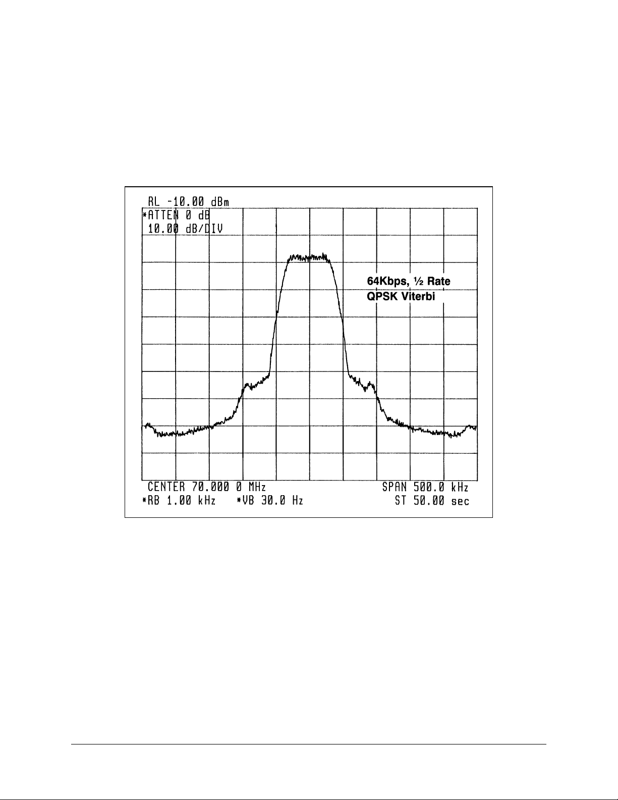
5.1.1 Modulator Checkout
A typical output spectrum is shown in Figure 5-1. If the output does not resemble this
picture, refer to the fault isolation in Section 5.2 to locate the problem.
Figure 5-1. Typical Output Spectrum
The carrier frequency is selected through the NMS.
5–2 Rev. 1
Page 48

SNM-1001 Network Control Modem Maintenance
5.1.2 Demodulator Checkout
The input to the demodulator card must be set within the proper frequency and power
level ranges for the demodulator to lock to the signal. Refer to Figure 5-2 and the table
below to check for proper E
b/N0
level.
The following table lists Comtech EFData’s conversion of (S+N)/N to S/N and E
1/2 data rate:
(dB) Code Rate 1/2
(S+N)/N S/N Eb/N
4.0 1.8 1.8
4.5 2.6 2.6
5.0 3.3 3.3
5.5 4.1 4.1
6.0 4.7 4.7
6.5 5.4 5.4
7.0 6.0 6.0
7.5 6.6 6.6
8.0 7.3 7.3
8.5 7.8 7.8
9.0 8.4 8.4
9.5 9.0 9.0
10.0 9.5 9.5
10.5 10.1 10.1
11.0 10.6 10.6
11.5 11.2 11.2
12.0 11.7 11.7
12.5 12.2 12.2
13.0 12.8 12.8
13.5 13.3 13.3
14.0 13.8 13.8
14.5 14.3 14.3
15.0 14.9 14.9
15.5 15.4 15.4
16.0 15.9 15.9
16.5 16.4 16.4
17.0 16.9 16.9
17.5 17.4 17.4
18.0 17.9 17.9
18.5 18.4 18.4
19.0 18.9 18.9
19.5 19.5 19.5
20.0 20.0 20.0
0
b/N0
for
Figure 5-2 is an example of the typical output spectrum noise for a 1/2 rate carrier
operating at an E
of 8.0 dB. (S+N)/N is measured by taking the average level of the
b/N0
noise and the average level of the top of the modem spectrum as shown. Use this
measurement for the first column on the above table. Read across the page to find the
S/N and E
Rev. 1 5–3
for the specific code rate.
b/N0
Page 49

Maintenance SNM-1001 Network Control Modem
Figure 5-2. Typical Output Spectrum Noise
5–4 Rev. 1
Page 50

SNM-1001 Network Control Modem Maintenance
With Noise
Without Noise
Figure 5-3. Typical Eye Constellations
Rev. 1 5–5
Page 51

Maintenance SNM-1001 Network Control Modem
5.1.3 Test Points
The modem does not have accessible test points. When troubleshooting is required at
board level, the cover must be removed.
The following is a list of test points located on the PCB, and a description of the signals
that should be present under normal operation.
5.1.3.1 Modulator Test Points
TP 1 DATA CLOCK TTL level clock that is locked to the incoming data to the interface
card.
TP 2 SYMBOL CLOCK TTL level clock that is locked to the incoming clock to the interface
card. This clock is r unning a t the s ymbol frequenc y and not at the
data rate. The f re que nc y is equal to:
BPSK = 2 x Bit Clock
•
QPSK1/2 = Bit Clock
•
QPSK3/4 = 2/3 Bit Clock
•
QPSK7/8 = 4/7 Bit Clock
•
TP 3 Q MIXER Analog output of the Q channe l ba seba nd re c onstruc tion f ilte r a nd
the input to the RF modulator.
TP 4 Q DIGITAL FILTER Analog output f rom the Digital filter.
TP 5 I DIGITAL FIL TER Analog output from the Digital filter.
TP 6 I MIXER Analog output of the I channel ba se ba nd rec onstruc tion filter and the
input to the RF modulator.
5–6 Rev. 1
Page 52

SNM-1001 Network Control Modem Maintenance
5.1.3.2 Demod/M&C/Interface Test Points
TP 3 +5V +5V
TP 4 GND Ground
TP 11 GND Gr ound
TP 12 SD Send Data
TP 13 TT Terminal Timing (Transmit Clock)
TP 14 RD Receive Data
TP 15 RT Receive Timing
TP 16 GND Gr ound
TP 18 I I Channel Analog R F Output
TP 19 Q Q Channel Analog R F O utput
TP 20 Q OFF Analog Q Channel D C O ffset Control
TP 21 Q CHAN Q Channel Analog Anti-Alias Filter
Output
TP 22 I CHAN I Channel Analog Anti-A lias Filte r
Output
TP 24 I OFF Analog I Channel D C O ffset Control
TP 25 GND Gr ound
TP 26 AGC DRV Analog AGC Drive
TP 27 Q A/D IN Q Channel Analog to Di g ita l Input
TP 28 AGC CTRL Digital AGC Control
TP 29 GND Gr ound
TP 30 I A/D IN I Channel Analog to Digital Input
TP 31 IF SYNTH REF (R143 must be populated) IF Synthesizer R e f e r e nc e
TP 34 DATCLK Data Rate Clock
TP 36 RX CLOCK Buffer Output CL K
TP 37 DP1 Constellation I Test Point
TP 38 DP2 Constellation Q Test Point
TP 41 SYMBCK Symbol Clock
D9 OVFL Buffer Overflow LED
D10 UNFL Buffer Underflow LED
D11 DON/PG XILINX Done Programming LED
Rev. 1 5–7
Page 53

Maintenance SNM-1001 Network Control Modem
5.2 Fault Isolation
The modem has been designed so that a qualified technician may isolate fault conditions
without removing the modem from its location. The fault monitoring capability of the
modem is designed to aid the operator in determining the cause of a failure.
System faults are reported in the Fault menu. Stored faults are reported in the StFaults
menu. The following list is to be used in isolating the problem and deciding the
appropriate action to be taken. Figure 5-4 and Figure 5-5 are diagrams of the SNM-1001
fault tree in the Burst mode and Continuous mode, respectively.
SNM-1001
FAULT TREE
MOD FAULT S
IF SYNTHESIZER
DATA CLOCK SYN
AGC
MODULE
DEMODFAULTS
IF SYNTHESIZER
MODULE
TX IF OUTPUT OFF
TX FAULT LED
111
111
1
11
111
TX FAULT RELAY
RX FAULT LED
RX FAULT RELAY
11
11
COM EQ FAULT LED
COM EQ FAULT RELAY
TX ALARM LED
INTERFACE FAUL T S
RX ALARM LED
COMMON EQUIPMENT FAULTS
BATTERY/CLOCK
-12VPOWER SUPPLY
+12VPOWER SUPPLY
+5VSUPPLY
CONTROLLER
INTERFACE MODULE
Figure 5-4. SNM-1001 Fault Tree (Burst Mode)
TX FAULT LED
TX IF OUTPUT OFF
RX FAULT LED
TX FAULT RELAY
COM EQ FAULT LED
RX FAULT RELAY
1
111
11
1111
COM EQ FAULT RELAY
1TX INTF FLTTX CLK ACTIVITY
1
TX ALARM LED
RX ALARM FAULT LED
5–8 Rev. 1
Page 54

SNM-1001 Network Control Modem Maintenance
SNM-1001
FAULT TREE
MOD FAULT S
IF SYNTHESIZER
DATA
CLOCK SYN
I CHANNEL
Q CHANNEL
AGC
MODULE
DEMODFAULTS
MODULE
IF SYNTHESIZER
I CHANNEL
Q CHANNEL
DESCRAMBLER
BER THRESHOLD
TX IF OUTPUT OFF
TX FAULT LED
111
111
1
11
111
TX FAULT RELAY
RX FAULT LED
RX FAULT RELAY
COM EQ FAULT LED
TX ALARM LED
COM EQ FAULT RELAY
INTERFACE FAUL T S
RX ALARM LED
BUFFER UNDERFLOW_
BUFFER OVERFLOW RX INTF FLTS
BUFFER CLOK ACT
TX INTF
FLTTX CLK ACTIVITY
COMMON EQUIPMENT FAULTS
1
1
1
1
1
1
1
1
1
1
1
1MODULE
1
BATTERY/CLOCK
-12VPOWER SUPPLY
+12VPOWER SUPPLY
+5VSUPPLY
CONTROLLER
INTERFACE MODULE
Figure 5-5. SNM-1001 Fault Tree (Continuous Mode)
TX FAULT LED
TX IF OUTPUT OFF
RX FAULT LED
TX FAULT RELAY
COM EQ FAULT LED
RX FAULT RELAY
1
111
11
1111
COM EQ FAULT RELAY
1
1
TX ALARM LED
1
1
1
RX ALARM FAULT LED
Rev. 1 5–9
Page 55

Maintenance SNM-1001 Network Control Modem
5.2.1 Modulator Faults
5.2.1.1 Continuous Mode
Fault/Alarm Possible Problem and Action
IF SYNTHESIZER Modulator IF synthesizer is faulted.
This is considered a major alarm and will turn OFF the modulator output.
Return the modem for repair.
DATA CL O CK SY N Transmit data clock sy nthe s iz e r fault.
This fault is an indication that the inte rnal cloc k VCO ha s not lock e d to the
incoming data cloc k , or the inte rna l c loc k s ynthesizer has not loc k e d to the
internal reference. T his is conside re d a major alarm and w ill turn OFF the
modulator output.
Check to see that the proper data rate has been set up and selected. Verify that
the incoming data rate matches what has been selected in the modem. Verify
the frequency of the input data clock to be within the lock range of 100 PPM.
If the inputs to the modem are all correct and the proble m still exists, replace
the modem and return for repair.
I CHANNEL Activity alarm for the I channel digital filter.
This alarm is cons ide re d a major alarm and will turn OFF the modulator IF
output.
An alarm in this position indicate s e ithe r a f a ult in the scra mbler or, if the
scrambler is disabled, it indicates a loss of inc om ing da ta . If the f a ult is a ctiv e
with the scram bler tur ned O FF, che c k to se e tha t the re is input da ta a t the da ta
I/O connector. If data is present, the problem could be in the interface section.
If the fault is active w ith the sc ra mbler turned ON, the problem could be in
the modulator section. R e turn the modem for re pair .
Q CHANNEL Activity alarm for the Q channe l dig ital filter.
Follow the same procedure as for the I channel.
AGC LEVEL Output power AG C le v e l fault.
Indicates that the leve l a t the modulator output is not the level that is
programmed. Replace the modem and return it for repair.
MODULE Modulator module fault.
Typically indic at es the modulator will not program . This could indicate a
problem in the interface between the modulator and M&C due to m odula tor
firmwa re be ing ins ta lle d inc orre c tly, or a pin not maki ng c ontac t . Ver ify the
modulator firmware is correctly insta lled. If the problem still exists , return the
modem for re pa ir .
5–10 Rev. 1
Page 56

SNM-1001 Network Control Modem Maintenance
5.2.2 Demodulator Faults
5.2.2.1 Burst Mode
Fault/Alarm Possible Problem and Action
IF SYNTHESIZER Demodulator IF synthesizer f a ult.
Indicates the dem odulat or IF s ynthesizer is f aulte d. This fault is a hardw a re
failure. Return the modem for repair.
MODULE De modulator module fault.
Typically indic a te s the de modulator will not program . This could indicate a
problem in the M&C or in the interface between the demodulator and M&C.
Return the modem for repair.
5.2.3 Transmit Interface Faults
Fault/Alarm Possible Problem and Action
TX CLOCK ACT Activity detector alarm of selected interface transmit clock.
Indicates the selected TX clock is not detected. Verify the signal at the
selected TX clock source. The interface will fall back to the internal clock
when this alarm is active.
5.2.4 Receive Interface Faults
5.2.4.1 Burst Mode
This fault is not applicable when the modem is in the Burst mode.
Rev. 1 5–11
Page 57

Maintenance SNM-1001 Network Control Modem
5.2.5 Common Equipment Faults
Fault/Alarm Possible Problem and Action
BATTERY/CLOCK M&C battery voltage or clock fault.
Indicates a low voltag e in the memory battery. Typically will be active when a
modem has be e n ha rd r e se t, or the firmware ha s be e n cha ng e d. When a hard
reset has been executed or the firmware has been changed, this fault may be
active when the modem is first turne d ON . It s hould c le ar a utom a tic a lly as the
battery charg e s up.
-12V -12V power supply fault.
Indicates a high or low v oltag e c ondition. L e v e l is
the -12V line from the power supply or on the boa r d. Che c k TP 2 on the M&C
section to verify the prope r -12V m onitor v olta g e (1.06V). If this v olta g e is not
correct, the modem will verify tha t the -12V supply is not at the proper level.
This would indicate the power supply is f aulte d. R e turn modem for repa ir .
+12V +12V power supply fa ult.
Use the same pr oc e dure a s with -12V fault. To ve rify the +12V pow e r s upply
voltage, check T P 4 on the M& C. A voltage of 3.81V will be monitored when
the +12V is at the proper level.
+5V +5V power supply fault.
Use the same pr oc e dure a s with -12V fault. To ve ri f y the +5V power s upply
voltage, check T P 5 on the M&C se c tion. A voltage of 2.5V will be monitored
when the +5V is at the proper level.
CONTROLR Controller fault.
Indicates loss of power in the M&C card. Typically indicates the controller has
gone through a powe r O N - OFF c ycle.
INTERFACE Interface module fault.
Indicates a problem in programming the interface. This could indicate a
problem in the M&C or in the interface between the interface section and
M&C. Return the modem for repair.
5%. Check for a short on
±
5–12 Rev. 1
Page 58

SNM-1001 Network Control Modem Maintenance
5.3 Module Identification
The modem PCBs each have an assembly number marked on the board. The latest
revision is stamped on the board, along with the serial number.
Comtech EFData tracks the hardware by the assembly number, revision, and serial
number.
When replacing a plug-on module, care must be taken to ensure proper
orientation of the card.
CAUTION
Refer to the individual sections on each module for location of the configuration
identification.
Refer to Table 5-1 for a list of part numbers and descriptions of various modules used in
the modem.
Table 5-1. Comtech EFData Part Numbers for Various Modules
Chassis Assembly Base Part #
Dash #
1
2
RF Modulator Part #
Dash #
2
RF Demodulator Part #
Dash #
2
Interface
EIA-422 AS/2524
5.4 Software Versions
S/W Version Firmware # Description of Change
1.1.1 3060-1- Original release.
2.1.1 3060-1A Added support for D oppler buffer and Comstre am compatibility
3.1.1 3060-1B Added sequential BPSK code rate suppor t.
3.1.2 3060-1C Correctional changes.
4.1.1 3060-1D Added Modem Type to Utility menu to allow SDM-100 or SDM-
4.1.2 3060-1E Correctiona l c hang e s .
4.1.3 3060-1F Correctional changes.
5.1.1 3060-1G Added support for Fa irchild c ompatibility.
5.1.2 3060-1H Correctional c hang e s .
6.2.1 3060-1I Added support for SDM-51 compatibility .
AS/5182-X
Description
AC, EFD, With Display
DC, EFD, With Display
AS/3995-X
Description
75
Modulator
Ω
AS/4401-X
Description
75
Demodulator
Ω
for Modulator Type and Demodula tor Type.
650 emulation.
Rev. 1 5–13
Page 59

Maintenance SNM-1001 Network Control Modem
7.2.1 3060-1J Added rev-emulation for bac kward-com pa tible ope ra tion. Added
ADPCM option, and changed a c quisition r a ng e to ± 35 kHz.
7.2.2 3060-1K Correctional c hang e s .
8.2.1 3060-1L Added re mote support of TX-IF output us ing R TS signal.
8.2.2 3060-1M Correctional changes.
9.2.1 3060-1N Added support for ASYNC/A UPC inte rface and support for 8-bit,
no parity.
10.3.1 3060-1P Added support f or ne w RF board.
11.4.1 4328-1- Update from FW/3060-1 adding support for SD M-150.
12.5.1 4328-1A Added Reed-Solomon support.
13.6.1 4328-1B Added spect ra l inv e r s ion.
13.6.2 4328-1C Correctional chang e s .
13.6.3 4328-1D Correctional changes.
13.6.4 4328-1E Correctional changes.
14.7.1 4969-14969-2-
14.7.2 4969-1A
4969-2A
14.7.3 4969-1B
4969-2B
14.7.4 4969-1C
4969-2C
15.7.1 4969-1D
4969-2D
15.7.2 4969-1E
4969-2E
15.7.3 4969-1F
4969-2F
15.7.4 4969-1G
4969-2G
15.7.5 4969-1H
4969-2H
15.7.6 4969-1J
4969-2J
15.7.7 4969-1K
4969-2K
15.7.8 4969-1L
4969-2L
Replaces FW/3060-1 and 4328-1, combining support f or
AS/2528 with support f or AS/4973.
Removed 38400 burs t s uppor t f or ne w RF Demod.
Added two new r e mote comma nds for network opera tion.
Correctional changes.
Added Asy nc information to rem ote s ta tus c ommands.
Affec ts only IDC-150 operations.
Allows 10 kbit/s for QPSK 1/2.
Fixed extended Eb/No for new A S/4973.
Fixed Viterbi based repor ting for Eb/N
Fixed bit error threshold ala rm.
Added support to allow N MS c ontrol RF dur ing s ystem fa ilure s .
Added support for NMS to a llow modem to have an option to
boot up with display SNM-1001 in front panel.
o.
5.5 Repackaging Requirements for Shipment
If it is necessary to return the modem for repair, the modem must be shipped in the
original factory packaging or equivalent packing material for protection.
Failure to comply with the repackaging requirements will void the warranty.
CAUTION
5–14 Rev. 1
Page 60

Appendix A.
REMOTE CONTROL OPERATION
A
This appendix describes the remote control operation of the SNM-1001.
• Firmware number: FW/4969-1L and FW/4969-2L
• Software version: 15.7.7
The -2 version is the PLCC (Plastic Leadless Chip Carrier) version, applicable to the
SDM-100A and -150A.
The -1 version is the 28-pin DIP version, applicable to the SDM-100 and -150.
Rev. 1 A–1
Page 61

Remote Control Operation SNM-1001 Network Control Modem
A.1 General
Remote controls and status information are transferred via an EI A485 (optional EI A232C)
serial communications link.
Commands and data are transferred on the remote control com munications link as
US ASCII-encoded character strings.
The remote communications link is operated in a half- duplex m ode.
Communications on the rem ote link are initiated by a rem o te controller or term inal. The
modem never transm its data on the link unless it is commanded to do so.
Since the SNM-1001 operates in both Burst and Continuous modes, command and
command parameter selection will be dependent upon whether the Transmit Mode has
been configured as Burst or Continuous, and whether the Receive Mode has been
configured as Burst or Continuous. The SNM-1001 modem will default to Transmit
Burst, Receive Burst modes after a cold startup, or when a hard reset has been initiated.
A–2 Rev. 1
Page 62

SNM-1001 Network Control Modem Remote Control Operation
A.2 Message Structure
The ASCII character form at used requires 11 bits/character:
• 1 start bit
• 7 information bits
• 1 parity bit
• 2 stop bits
Messages on the remote link fall into the categories of commands and responses.
Commands are m essag es w hich are transmitted to a satellite modem, while responses are
messages returned by a satellite m odem in response to a com mand.
The general message structure is as follows:
• Start Character
• Device Address
• Command/Response
• End of Message Character
A.2.1 Start Character
A single character precedes all messages transmitted on the remote link. This character
flags the start of a message. This character is:
“<”
•
•
for commands
“>”
for responses
A.2.2 Device Address
The device address is the address of the one satellite modem which is designated to receiv e
a transmitted command, or w hich is responding to a com m and.
Valid device addresses are 1 to 3 characters long, and in the range of 1 to 255. Address 0 is
reserved as a global address which simultaneously addresses all dev ices on a g iv en
communications link. Devices do not acknowledge global commands.
Each satellite modem which is connected to a com mon remote comm unications link must
be assigned its own unique address. Addresses are software selectable at the modem, and
must be in the range of 1 to 255.
Rev. 1 A–3
Page 63

Remote Control Operation SNM-1001 Network Control Modem
A.2.3 Command/Response
The command/response portion of the messag e contains a v ariable-length character
sequence which conveys command and response data.
If a satellite modem receiv es a message addressed to it which does not match the
established protocol or cannot be implemented, a negativ e acknowledg ment message is sent
in response. This message is:
add/?ER1_parity error'cr''lf']
• >
(Error message for received parity errors.)
>add/?ER2_invalid parameter'cr''lf']
•
(Error message for a recognized command which cannot be implemented or has parameters
which are out of range.)
add/?ER3_unrecognizable command'cr''lf']
• >
(Error message for unrecognizable command or bad command syntax.)
>add/?ER4_modem in local mode'cr''lf']
•
(Modem in local error; send the REM command to go to remote mode.)
>add/?ER5_hard coded parameter'cr'' lf']
•
(Error message indicating that the parameter is hardware dependent and may not be changed
remotely.)
Note:
add is used to indicate a valid 1 to 3 character device address in the range
between 1 and 255.
A.2.4 End Character
Each message is ended with a single character which sig n als the end of the m essag e:
“cr”
•
“]”
•
Carriage return character for commands
End bracket for responses
A–4 Rev. 1
Page 64

SNM-1001 Network Control Modem Remote Control Operation
A.3 Configuration Commands/Responses
A.3.1 Modulator
Modulator
Frequency
RF Output
(IF Output)
Modulator
Rate Preset
Assignment
Modulator
Rate Preset
Selection
Command:
Response:
Status:
Response:
Command:
Response:
Status:
Response:
Command:
Response
Status:
Response:
Command:
Response:
Status:
<add/MF_nnn.nnnn'cr'
>add/MF_nnn.nnnn'cr'
RF_OFF'cr''lf']
<add/MF_'cr'
>add/MF_nnn.nnnn'cr''lf']
<add/RF_xxx'cr'
>add/RF_xxx'cr''lf']
<add/RF_'cr'
>add/RF_xxx'cr''lf']
<add/AMRx_nnnn_mmm.mmm'cr'
>add/AMRx_nnnn_mmm.mmm'cr''lf']
<add/AMRx_'cr'
>add/AMRx_nnnn_mmm.mmm'cr''lf']
<add/SMRx_'cr'
>add/SMRx_'cr'
RF_OFF'cr''lf']
See MR command.
Where: nnn.nnnn = Frequency in MHz, 50.0000 to
180.0000, in 2.5 kHz steps.
Note: When the modulator frequency is program med, the
RF output is switched off.
Where: xxx = ON or OFF.
Where:
x = A, B, C, D, or V (Preset designator).
nnnn = 1/2, 3/4, 7/8, or BP12 (Coder rat e).
mmm.mmm = Data rate in kHz.
Notes:
1. When ADPCM Interface is selected, only 32.000 and
64.000 are allowed.
2. When the Async Interface is used. I f the ASYNC
baud rate is higher than allowable for the new data
rate, the maximum baud rate will be select ed
automatically.
Where: x = A, B, C, D, or V (Preset designator).
Note: Setting the m odul ator rate turns off the RF transmitter.
Modulator
Rate
Variable
Assignment
& Selection
Set
Modulator
Power
Offset
Command:
Response:
Status:
Command:
Response:
Status:
Response:
<add/SMRV_nnnn_mmm.mmm'cr'
>add/SMRV_nnnn_mmm.mmm'cr'
RF_OFF'cr''lf']
See MR command.
<add/MPO_snn.n'cr'
>add/MPO_snn.n'cr''lf']
<add/MPO_'cr'
>add/MPO_snn.n'cr''lf']
Where:
nnnn = 1/2, 3/4, 7/8, or BP12 (Coder rat e).
mmm.mmm = Data rate in kHz.
Notes:
1. Setting the modulator turns off the RF transm itter.
2. When ADPCM Interface is selected, only 32.000 and
64.000 are allowed.
3. When the Async Interface is used. I f the ASYNC
baud rate is higher than allowable for the new data
rate, the maximum baud rate will be select ed
automatically.
Where: snn.n = +49. 9 to -49.9, in 0.1 dB increments.
Note: The modulator power offset i s added to the nominal
power level to adjust the transm i t power range.
Rev. 1 A–5
Page 65

Remote Control Operation SNM-1001 Network Control Modem
Set
Modulator
Output
Power Level
Scrambler
Enable
Differential
Encoder
Enable
Modulator
Type
Modulator
Encoder
Type
Command:
Response:
Status:
Response:
Command:
Response:
Status:
Response:
Command:
Response:
Status:
Response:
Command:
Response:
Status:
Response:
Command:
Response:
Status:
Response:
<add/MOP_snn.n'cr'
>add/MOP_snn.n'cr''lf']
<add/MOP_'cr'
>add/MOP_snn.n'cr''lf']
<add/SE_xxx'cr'
>add/SE_xxx'cr''lf']
<add/SE_'cr'
>add/SE_xxx'cr''lf']
<add/DENC_xxx'cr'
>add/DENC_xxx'cr''lf']
<add/DENC_'cr'
>add/DENC_xxx'cr''lf']
<add/MT_xxxx'cr'
>add/MT_xxxx'cr''lf']
<add/MT_xxxx'cr'
>add/MT_xxxx'cr''lf']
<add/MET_xxx'cr'
>add/MET_xxx'cr''lf']
<add/MET_xxx'cr'
>add/MET_xxx'cr''lf']
Where: snn.n = -30. 0 to -5.0, in 0.1 steps (nominal range in
dBm).
Notes:
1. The nominal power range is modified relative to the
value specified by the modulator power offset
(MPO_).
2. The MOP_ command will return status only when
local AUPC is enabled.
Where: xxx = ON or OFF.
Where: xxx = ON or OFF.
Where: xxxx = INTL (INTELSAT OP EN NETWORK), EFD
(COMTECH EFDATA CLOSED NETWORK), CSC
(COMSTREAM CLOSED NETWORK), FDC (FAIRCHILD
CLOSED NETWORK), or SDM51 (SDM51 COMPATIBLE).
Where: xxx = VIT (K-7 VITERBI ENCOD ER) or SEQ
(SEQUENTIAL ENCODER).
Transmit
BPSK Data
Ordering
Modulator
Spectrum
Rotation
ReedSolomon
Encoder
Enable
Modulator
Spectrum
Rotation
Command:
Response:
Status:
Response:
Command:
Response:
Status:
Response:
Command:
Response:
Status:
Response:
Command:
Response:
Status:
Response:
<add/TDA_xxx'cr'
>add/TDA_xxx'cr''lf']
<add/TDA_xxx'cr'
>add/TDA_xxx'cr''lf']
<add/MSR_xxxx'cr'
>add/MSR_xxxx'cr''lf']
<add/MSR_'cr'
>add/MSR_xxxx'cr''lf']
<add/RSEN_xxx'cr'
>add/RSEN_xxx'cr'lf']
<add/RSEN_'cr'
>add/RSEN_xxx'cr'lf']
<add/MSR_xxxx'cr'
>add/MSR_xxxx'cr''lf']
<add/MSR_'cr'
>add/MSR_xxxx'cr''lf']
Where: xxx = NRM (STANDARD) or INV (NON STANDARD).
Where: xxxx = NRM (n ormal spectrum) o r INV (inve rted
spectrum).
Where: xxx = ON or OFF.
Where: xxxx = NRM (n ormal spectrum) o r INV (inve rted
spectrum).
A–6 Rev. 1
Page 66

SNM-1001 Network Control Modem Remote Control Operation
A.3.2 Demodulator
Set Demod
Frequency
Demod
Rate Preset
Assignment
Demod
Rate Preset
Selection
Demod
Rate
Variable
Assignment
& Selection
Command:
Response:
Status:
Response:
Command:
Response
Status:
Response:
Command:
Response:
Status:
Command:
Response:
Status:
<add/DF_nnn.nnnn'cr'
>add/DF_nnn.nnnn'cr''lf']
<add/DF_'cr'
>add/DF_nn.nnnn'cr''lf']
<add/ADRx_nnnn_mmm.mmm'cr'
>add/ADRx_nnnn_mmm.mmm'cr''lf']
<add/ADRx_'cr'
>add/ADRx_nnnn_mmm.mmm'cr''lf']
<add/SDRx_'cr'
>add/SDRx_'cr''lf']
See DR command.
<add/SDRV_nnnn_mmm.mmm'cr'
>add/SDRV_nnnn_mmm.mmm'cr''lf']
See DR command.
Where: nnn.nnnn = Frequency in MHz, 50.0000 to
180.0000, in 2.5 kHz steps.
Where:
x = A, B, C, D, or V (Preset designator).
nnnn = 1/2, 3/4, 7/8, or BP12 (Dec oder rate).
mmm.mmm = Data rate in kHz.
Notes:
1. When ADPCM Interface is selected, only 32.000 and
64.000 are allowed.
2. When the Async Interface is used. I f the ASYNC
baud rate is higher than allowable for the new data
rate, the maximum baud rate will be select ed
automatically.
Where: x = A, B, C, D, or V (Preset designator).
Where:
nnnn = 1/2, 3/4, 7/8, or BP12 (Dec oder rate).
mmm.mmm = Data rate in kHz.
Notes:
1. When ADPCM Interface is selected, only 32.000 and
64.000 are allowed.
2. When the Async Interface is used. I f the ASYNC
baud rate is higher than allowable for the new data
rate, the maximum baud rate will be select ed
automatically.
Descramble
Enable
Differential
Decoder
Enable
RF
Loopback
IF
Loopback
Command:
Response:
Status:
Response:
Command:
Response:
Status:
Response:
Command:
Response:
Status:
Response:
Command:
Response:
Status:
Response:
<add/DE_xxx'cr'
>add/DE_xxx'cr''lf']
<add/DE_'cr'
>add/DE_xxx'cr''lf']
<add/DDEC_xxx'cr'
>add/DDEC_xxx'cr''lf']
<add/DDEC_'cr'
>add/DDEC_xxx'cr''lf']
<add/RFL_xxx'cr'
>add/RFL_xxx'cr''lf']
<add/RFL_'cr'
>add/RFL_xxx'cr''lf']
<add/IFL_xxx'cr'
>add/IFL_xxx'cr''lf']
<add/IFL_'cr'
>add/IFL_xxx'cr''lf']
Where: xxx = ON or OFF.
Where: xxx = ON or OFF.
Where: xxx = ON or OFF.
Where: xxx = ON or OFF.
Rev. 1 A–7
Page 67

Remote Control Operation SNM-1001 Network Control Modem
Sweep
Center
Frequency
Sweep
Width
Range
Bit Error
Rate
Threshold
Demod
Type
Demod
Decoder
Type
Receive
BPSK Data
Ordering
Command:
Response:
Status:
Response:
Command:
Response:
Status:
Response:
Command:
Response:
Status:
Response:
Command:
Response:
Status:
Response:
Command:
Response:
Status:
Response:
Command:
Response:
Status:
Response:
<add/SCF_snnnnn'cr'
>add/SCF_snnnnn'cr''lf']
<add/SCF_'cr'
>add/SCF_snnnnn'cr''lf']
<add/SWR_nnnnn'cr'
>add/SWR_nnnnn'cr''lf']
<add/SWR_'cr'
>add/SWR_nnnnn'cr''lf']
<add/BERT_xxxx'cr'
>add/BERT_xxxx'cr''lf']
<add/BERT_'cr'
>add/BERT_xxxx'cr''lf']
<add/DT_xxxx'cr'
>add/DT_xxxx'cr''lf']
<add/DT_xxxx'cr'
>add/DT_xxxx'cr''lf']
<add/DDT_xxx'cr'
>add/DDT_xxx'cr''lf']
<add/DDT_xxx'cr'
>add/DDT_xxx'cr''lf']
<add/RDA_xxx'cr'
>add/RDA_xxx'cr''lf']
<add/RDA_xxx'cr'
>add/RDA_xxx'cr''lf']
Where: snnnnn = -35000 to +35000, i n 1 Hz steps.
Where: nnnnn = 0 to 70000, in 1 Hz steps.
Where: xxxx = NONE, or 1 E
-n
(where n = 3, 4, 5, 6, 7, or 8).
Where: xxxx = INTL (INTELSAT OP EN NETWORK), EFD
(COMTECH EFDATA CLOSED NETWORK), CSC
(COMSTREAM CLOSED NETWORK), or FDC (FAIRCHILD
CLOSED NETWORK).
Where: xxx = VIT (K-7 VITERBI ENCOD ER) or SEQ
(SEQUENTIAL ENCODER).
Where: xxx = NRM (STANDARD) or INV (NON STANDARD).
Demod
Spectrum
Rotation
ReedSolomon
Decoder
Enable
Command:
Response:
Status:
Response:
Command:
Response:
Status:
Response:
<add/DSR_xxxx'cr'
>add/DSR_xxxx'cr''lf']
<add/DSR_'cr'
>add/DSR_xxxx'cr''lf']
<add/RSDE_xxx'cr'
>add/RSDE_xxx'cr'lf']
<add/RSDE_'cr'
>add/RSDE_xxx'cr'lf']
Where: xxxx = NRM (n ormal spectrum) o r INV (inve rted
spectrum).
Where: xxx = ON, OFF, or COR R_OFF
A–8 Rev. 1
Page 68

SNM-1001 Network Control Modem Remote Control Operation
A.3.3 Interface
Transmit
Clock
Transmit
Clock
Phase
Buffer Clock Command:
Receive
Clock
Phase
Baseband
Loop Back
Interface
Buffer Size
Command:
Response:
Status:
Response:
Command:
Response:
Status:
Response:
Response:
Status:
Response:
Command:
Response:
Status:
Response:
Command:
Response:
Status:
Response:
<add/TC_xxx'cr'
>add/TC_xxx'cr''lf']
<add/TC_'cr'
>add/TC_xxx'cr''lf']
<add/TCP_xxxx'cr'
>add/TCP_xxxx'cr''lf']
<add/TCP_'cr'
>add/TCP_xxxx'cr''lf']
<add/BC_xxx'cr'
>add/BC_xxx'cr''lf']
<add/BC_'cr'
>add/BC_xxx'cr''lf']
<add/RCP_xxxx'cr'
>add/RCP_xxxx'cr''lf']
<add/RCP_'cr'
>add/RCP_xxxx'cr''lf']
<add/BBL_xxx'cr'
>add/BBL_xxx'cr''lf']
<add/BBL_'cr'
>add/BBL_xxx'cr''lf']
Where: xxx = INT (internal SCT c lock), EXT (external TX
terrestrial clock), or SAT (receive satellite clock).
Where: xxxx = NRM (n ormal clock phasi ng), INV (inverted
clock phasing), or AUTO (automatic clock phasing).
Where: xxx = INT (internal SCT c lock), EXT (external TX
terrestrial clock), SAT (receive satellite clock), or REF (external
reference clock).
Where: xxxx = NRM (n ormal clock phasi ng) or INV (inverted
clock phasing).
Where: xxx = ON or OFF.
Buffer size programming is supported in two formats; bits, or
milli-seconds. The select ed format must be chosen using the
buffer programming command (IBP_).
Interface
Buffer Size
(Bit Format)
Interface
Buffer Size
(Millisecond
Format)
Interface
Buffer
Center
Interface
Buffer
Program
Command:
Response:
Status:
Response:
Command:
Response:
Status:
Response:
Command:
Response:
Command:
Response:
Status:
Response:
<add/IBS_nnnnn'cr'
>add/IBS_nnnnn'cr''lf']
<add/IBS_'cr'
>add/IBS_nnnnn'cr''lf']
<add/IBS_nn'cr'
>add/IBS_nn'cr''lf']
<add/IBS_'cr'
>add/IBS_nn'cr''lf']
<add/IBC_'cr'
>add/IBC_'cr''lf']
<add/IBP_xxx'cr'
>add/IBP_xxx'cr''lf']
<add/IBP_'cr'
>add/IBP_xxx'cr''lf']
Where: nnnnn = 64 to 65536, in 16 bi t i ncrements.
Where: nn = 0 to 50 (buffer s i ze in milli-seconds).
Where: xxx = BIT S or MS (milli-seconds).
Rev. 1 A–9
Page 69

Remote Control Operation SNM-1001 Network Control Modem
Interface
ADPCM
Program
Interface
Subscriber/
Trunk
Emulation
E & M
Signal Type
Interface
Encoding
Law
Off Hook
Alert Enable
Interface
Service
Channel
Level
Command:
Response:
Status:
Response:
Command:
Response:
Status:
Response:
Command:
Response:
Status:
Response:
Command:
Response:
Status:
Response:
Command:
Response:
Status:
Response:
Command:
Response:
Status:
Response:
<add/ADP_xxx'cr'
>add/ADP_xxx'cr''lf']
<add/ADP_'cr'
>add/ADP_xxx'cr''lf']
<add/SBTR_xxx'cr'
>add/SBTR_xxx'cr''lf']
<add/SBTR_'cr'
>add/SBTR_xxx'cr''lf']
<add/EMS_n'cr'
>add/EMS_n'cr''lf']
<add/EMS_'cr'
>add/EMS_n'cr''lf']
<add/LAW_y'cr'
>add/LAW_y'cr''lf']
<add/LAW_'cr
>add/LAW_y'cr''lf']
<add/HOOK_xxx'cr'
>add/HOOK_xxx'cr''lf']
<add/HOOK_'cr
>add/HOOK_xxx'cr''lf']
<add/ISCL_xx_nnn'cr'
>add/ISCL_xx_nnn'cr''lf']
<add/ISCL_xx'cr'
>add/ISCL_xx_nnn'cr''lf']
Where: xxx = ON or OFF.
Note: Only valid when ADPCM board is installed.
Where: xxx = SUB or TRK.
Note: Only valid when ADPCM board is installed.
Where: n = 1 to 5, in steps of 1.
Note: Only valid when ADPCM board is installed.
Where: y = A (A-Law) or U (u-Law).
Where: xxx = ON or OFF.
Note: Only valid when ADPCM board is installed.
Where:
xx = TX or RX (service channel designator).
nnn = -20 to +10, in steps of 1 (servi ce channel level in
dBm).
Note: Only valid when ADPCM board is installed.
Interface
RD Signal
Interface
SD Signal
Interface
RR Signal
Interface
DM Signal
Interface
ASYNC
Communications
Program
Command:
Response:
Status:
Response:
Command:
Response:
Status:
Response:
Command:
Response:
Status:
Response:
Command:
Response:
Status:
Response:
Command:
Response:
Status:
Response:
<add/RD_xxx'cr'
>add/RD_xxx'cr''lf']
<add/RD_'cr'
>add/RD_xxx'cr''lf']
<add/SD_xxx'cr'
>add/SD_xxx'cr''lf']
<add/SD_'cr'
>add/SD_xxx'cr''lf']
<add/RR_xxx'cr'
>add/RR_xxx'cr''lf']
<add/RR_'cr'
>add/RR_xxx'cr''lf']
<add/DM_xxx'cr'
>add/DM_xxx'cr''lf']
<add/DM_'cr'
>add/DM_xxx'cr''lf']
<add/ACP_xxx'cr'
>add/ACP_xxx'cr''lf']
<add/ACP_'cr'
>add/ACP_xxx'cr''lf']
Where: xxx = NRM or INV.
Note: Only valid when ADPCM board is installed.
Where: xxx = NRM or INV.
Note: Only valid when ADPCM board is installed.
Where: xxx = NRM or INV.
Note: Only valid when ADPCM board is installed.
Where: xxx = NRM or INV.
Note: Only valid when ADPCM board is installed.
Where: xxx = ON or OFF.
Note: Only valid when ASYNC board is installed.
A–10 Rev. 1
Page 70

SNM-1001 Network Control Modem Remote Control Operation
ASYNC
Transmit
Overhead
Baud Rate
ASYNC
Receive
Overhead
Baud Rate
ASYNC
Transmit
Channel
Character
Length
ASYNC
Receive
Channel
Character
Length
ASYNC
Transmit
Channel
Stop Bits
ASYNC
Receive
Channel
Stop Bits
Command:
Response:
Status:
Response:
Command:
Response:
Status:
Response:
Command:
Response:
Status:
Response:
Command:
Response:
Status:
Response:
Command:
Response:
Status:
Response:
Command:
Response:
Status:
Response:
<add/TOBR_nnnnn'cr'
>add/TOBR_nnnnn'cr''lf']
<add/TOBR_'cr'
>add/TOBR_nnnnn'cr''lf']
<add/ROBR_nnnnn'cr'
>add/ROBR_nnnnn'cr''lf']
<add/ROBR_'cr'
>add/ROBR_nnnnn'cr''lf']
<add/TCCL_n'cr'
>add/TCCL_n'cr''lf']
<add/TCCL_'cr'
>add/TCCL_n'cr''lf']
<add/RCCL_n'cr'
>add/RCCL_n'cr''lf']
<add/RCCL_'cr'
>add/RCCL_n'cr''lf']
<add/TOSB_n'cr'
>add/TOSB_n'cr''lf']
<add/TOSB_'cr'
>add/TOSB_n'cr''lf']
<add/RCSB_n'cr'
>add/RCSB_n'cr''lf']
<add/RCSB_'cr'
>add/RCSB_n'cr''lf']
Where: nnnnn = 150, 300, 600, 1200, or 2400.
Note: Only valid when ASYNC board is installed with ASYNC
enabled.
Where: nnnnn = 150, 300, 600, 1200, or 2400.
Note: Only valid when ASYNC board is installed with ASYNC
enabled.
Where: n = 5, 6, 7, or 8 (characters).
Note: Only valid when ASYNC board is installed with ASYNC
enabled.
Where: n = 5, 6, 7, or 8 (characters).
Note: Only valid when ASYNC board is installed with ASYNC
enabled.
Where: n = 1 or 2 (stop bits).
Note: Only valid when ASYNC board is installed with ASYNC
enabled.
Where: n = 1 or 2 (stop bits).
Note: Only valid when ASYNC board is installed with ASYNC
enabled.
ASYNC
Transmit
Overhead
Channel
Parity
ASYNC
Receive
Overhead
Channel
Parity
Interface
Loop
Timing
ASYNC
Overhead
Communications
Type
Interface
Wire Type
Terrestrial
Communications
Type
Command:
Response:
Status:
Response:
Command:
Response:
Status:
Response:
Command:
Response:
Command:
Response:
Status:
Response:
Command:
Response:
Command:
Response:
Status:
Response:
<add/TOCP_xxxx'cr'
>add/TOCP_xxxx'cr''lf']
<add/TOCP_'cr'
>add/TOCP_xxxx'cr''lf']
<add/ROCP_xxxx'cr'
>add/ROCP_xxxx'cr''lf']
<add/ROCP_'cr'
>add/ROCP_xxxx'cr''lf']
<add/ILT_xxx'cr'
>add/ILT_xxx'cr''lf']
<add/OCT_xxxxx'cr'
>add/OCT_xxxxx'cr''lf']
<add/OCT_'cr'
>add/OCT_xxxxx'cr''lf']
<add/IWT_xxxxxxx'cr'
>add/IWT_xxxxxxx'cr''lf']
<add/TCT_xxxxx'cr'
>add/TCT_xxxxx'cr''lf']
<add/TCT_'cr'
>add/TCT_xxxxx'cr''lf']
Where: xxxx = ODD, EVEN, or NONE.
Note: Only valid when ASYNC board is installed with ASYNC
enabled.
Where: xxxx = ODD, EVEN, or NONE.
Note: Only valid when ASYNC board is installed with ASYNC
enabled.
Where: xxx = ON or OFF.
Where: xxxxx = RS232 or RS485.
Note: Only valid when ASYNC board is installed.
Where: xxxxxxx = 2_WIRE or 4_WIRE.
Note: Only valid when ASYNC board is installed.
Where: xxxxx = RS422 or V.35.
Note: Only valid when ASYNC board is installed.
Rev. 1 A–11
Page 71

Remote Control Operation SNM-1001 Network Control Modem
Interface
SD Signal
Command
Interface
RS Signal
Command
Interface
MC Signal
Command
Interface TT
Signal
Command
Interface
RD Signal
Command
Interface
RR Signal
Command
Interface
DM Signal
Command
Interface
CS Signal
Command
Command:
Response:
Command:
Response:
Command:
Response:
Command:
Response:
Command:
Response:
Command:
Response:
Command:
Response:
Command:
Response:
<add/ISSD_xxx'cr'
>add/ISSD_xxx'cr''lf']
<add/ISRS_xxx'cr'
>add/ISRS_xxx'cr''lf']
<add/ISMC_xxx'cr'
>add/ISMC_xxx'cr''lf']
<add/ISTT_xxx'cr'
>add/ISTT_xxx'cr''lf']
<add/ISRD_xxx'cr'
>add/ISRD_xxx'cr''lf']
<add/ISRR_xxx'cr'
>add/ISRR_xxx'cr''lf']
<add/ISDM_xxx'cr'
>add/ISDM_xxx'cr''lf']
<add/ISCS_xxx'cr'
>add/ISCS_xxx'cr''lf']
Where: xxx = NRM or INV.
Note: Only valid when ASYNC board is installed.
Where: xxx = NRM or INV.
Note: Only valid when ASYNC board is installed.
Where: xxx = NRM or INV.
Note: Only valid when ASYNC board is installed.
Where: xxx = NRM or INV.
Note: Only valid when ASYNC board is installed.
Where: xxx = NRM or INV.
Note: Only valid when ASYNC board is installed.
Where: xxx = NRM or INV.
Note: Only valid when ASYNC board is installed.
Where: xxx = NRM or INV.
Note: Only valid when ASYNC board is installed.
Where: xxx = NRM or INV.
Note: Only valid when ASYNC board is installed.
Interface
RT Signal
Command
Interface ST
Signal
Command
Command:
Response:
Command:
Response:
<add/ISRT_xxx'cr'
>add/ISRT_xxx'cr''lf']
<add/ISST_xxx'cr'
>add/ISST_xxx'cr''lf']
Where: xxx = NRM or INV.
Note: Only valid when ASYNC board is installed.
Where: xxx = NRM or INV.
Note: Only valid when ASYNC board is installed.
A–12 Rev. 1
Page 72

SNM-1001 Network Control Modem Remote Control Operation
A.3.4 System
Time Of
Day
Date Command:
Remote Command:
Clear
Stored
Faults
Modem
Operation
Mode
RTS TX-IF
Control
Mode
Command:
Response:
Status:
Response:
Response:
Status:
Response:
Response:
Command:
Response:
Command:
Response:
Status:
Response:
Command:
Response:
Status:
Response:
<add/TIME_hh:mmxx'cr'
>add/TIME_hh:mmxx'cr''lf']
<add/TIME_'cr'
>add/TIME_hh:mmxx'cr''lf']
<add/DATE_mm/dd/yy'cr'
>add/DATE_mm/dd/yy'cr''lf']
<add/DATE_'cr'
>add/DATE_mm/dd/yy'cr''lf']
<add/REM_'cr'
>add/REM_'cr''lf']
<add/CLSF_'cr'
>add/CLSF_'cr''lf']
<add/MOM_xxxxxxx'cr'
>add/MOM_xxxxxxx'cr''lf']
<add/MOM_'cr'
>add/MOM_xxxxxxx'cr''lf']
<add/RTSM_xxx'cr'
>add/RTSM_xxx'cr''lf']
<add/RTSM_'cr'
>add/RTSM_xxx'cr''lf']
Where:
hh = 1 to 12 (hours).
mm = 00 to 59 (minutes).
xx = AM or PM.
Where:
mm = 1 to 12 (mont h).
dd = 1 to 31 (day).
yy = 00 to 99 (year).
This command c onf i gures the modem for rem ote operation.
The SDM100A will respond to any status request at any time.
However, the SDM100A must be in 'Rem ote Mode' to change
configuration parameters .
This command is used to clear all stored faults logged by the
SDM100A.
Where: xxxxxxx = TX_ON LY, RX_ONLY, or D UPLEX.
This command configures the modem for simplex or duplex
operation modes. When transmit only mode is selected
receive faults are inhibited and when receive only mode is
selected transmi t faults are inhibited.
Where: xxx = ON or OFF.
This command configures the modem for t he RTS TX-IF
control mode. If "ON" is selec ted, the TX-IF output will only be
turned on if the incoming RTS signal is asserted (also t he TXIF output has to be programmed ON and no major modulator
faults are present). If " OFF" i s selected, the TX-IF output will
operate normal ignoring the RTS si gnal .
RF Mode
Control
Command:
Response:
Status:
Response:
<add/RFMD_xxxx'cr'
>add/RFMD_xxxx'cr''lf']
<add/RFMD_xxxx'cr'
>add/RFMD_xxxx'cr''lf']
Where: xxxx = NRM (N orma l Mode), PWR (Turn RF off on
power up), COMM (Turn RF off on power up and loss of
remote comm uni cations after 10 seconds), CD (Turn RF ON
when carrier is detected, turn RF OFF when no carrier is
detected. For the RF ON condition, the TX-IF must be
programmed ON. Note: RTS TX-IF, when enabled over-rides
CD).
This command allows f or t he RF output to be enabled or
disabled depending on the following described c ondi tions. One
application for this command will be in demand network
systems.
A.3.5 AUPC
AUPC Local
Enable
Rev. 1 A–13
Command:
Response:
Status:
Response:
<add/LPC_xxx'cr'
>add/LPC_xxx'cr''lf']
<add/LPC_'cr'
>add/LPC_xxx'cr''lf']
Where: xxx = ON or OFF.
Note: When program med ON, the MOP (Modulator Output
Power) command is not all owed, only MOP status is allowed.
Page 73

Remote Control Operation SNM-1001 Network Control Modem
AUPC
Nominal
Power Level
AUPC
Maximum
Power Limit
AUPC
Minimum
Power Limit
AUPC Eb/N
Target Set
Point
AUPC
Maximum
Tracking
Rate
AUPC Local
Carrier Loss
Action
Command:
Response:
Status:
Response:
Command:
Response:
Status:
Response:
Command:
Response:
Status:
Response:
0
Command:
Response:
Status:
Response:
Command:
Response:
Status:
Response:
Command:
Response:
Status:
Response:
<add/NOMP_snn.n'cr'
>add/NOMP_snn.n'cr''lf']
<add/NOMP_'cr'
>add/NOMP_snn.n'cr''lf']
<add/MAXP_snn.n'cr'
>add/MAXP_snn.n'cr''lf']
<add/MAXP_'cr'
>add/MAXP_snn.n'cr''lf']
<add/MINP_snn.n'cr'
>add/MINP_snn.n'cr''lf']
<add/MINP_'cr'
>add/MINP_snn.n'cr''lf']
<add/ENSP_nn.n'cr'
>add/ENSP_nn.n'cr''lf']
<add/ENSP_'cr'
>add/ENSP_nn.n'cr''lf']
<add/MAXT_n.n'cr'
>add/MAXT_n.n'cr''lf']
<add/MAXT_'cr'
>add/MAXT_n.n'cr''lf']
<add/LCL_xxxx'cr'
>add/LCL_xxxx'cr''lf']
<add/LCL_'cr'
>add/LCL_xxxx'cr''lf']
Where: snn.n = -30. 0 to -5.0, in 0.1 steps (nominal range in
dBm).
Note: The nominal power range is modified relative to the
value specified by the modulator power offset (MPO_).
Where: snn.n = -30. 0 to -5.0, in 0.1 steps (nominal range in
dBm).
Note: The nominal power range is modified relative to the
value specified by the modulator power offset (MPO_).
Where: snn.n = -30. 0 to -5.0, in 0.1 steps (nominal range in
dBm).
Note: The nominal power range is modified relative to the
value specified by the modulator power offset (MPO_).
b/N0
Where: nn.n = 3.2 t o 16. 0, in 0.1 increments (E
in dB).
Where: n.n = 0.5 t o 6. 0, in 0.5 increments (max. tracking rate
in dBm/minut e).
Wh ere: xxxx = HOLD, NOM, or MA X (power level set ting when
local carrier loss).
AUPC
Remote
Carrier Loss
Action
Remote
Modem
AUPC
Commands
Remote
AUPC
Enable
Remote
Interface
Baseband
Loop Back
Command:
Response:
Status:
Response:
Command:
Response:
Status:
Response:
Command:
Response:
Status:
Response:
<add/RCL_xxxx'cr'
>add/RCL_xxxx'cr''lf']
<add/RCL_'cr'
>add/RCL_xxxx'cr''lf']
<add/RPC_xxx'cr'
>add/RPC_xxx'cr''lf']
<add/RPC_'cr'
>add/RPC_xxx'cr''lf']
<add/RBBL_xxx'cr'
>add/RBBL_xxx'cr''lf']
<add/RBBL_'cr'
>add/RBBL_xxx'cr''lf']
Wh ere: xxxx = HOLD, NOM, or MA X (power level set ting when
remote carrier loss).
Notes:
1. Always wait 3 seconds between consecutive remote
modem command/status polls .
2. If Local AUP C i s not enabled, status commands will
return last known condition. They will also request
status from the remote modem. This allows a second
request to return proper status .
Where: xxx = ON, OFF, or UNK (remote AUPC enable).
Where: xxx = ON, OFF, or UNK (remote baseband loop back
enable).
A–14 Rev. 1
Page 74

SNM-1001 Network Control Modem Remote Control Operation
A.4 Status Commands/Responses
A.4.1 Configuration
Modulator
Config
Status
Command:
Response:
<add/MCS_'cr'
>add/MCS_'cr'
RF_xxx'cr'
MF_nnn.nnnn'cr'
MR_nnnn_mmm.mmm'cr'
AMRA_nnnn_mmm.mmm'cr'
AMRB_nnnn_mmm.mmm'cr'
AMRC_nnnn_mmm.mmm'cr'
AMRD_nnnn_mmm.mmm'cr'
AMRV_nnnn.mmm.mmm'cr'
MPO_snn.n'cr'
MOP_snn.n'cr'
SE_xxx'cr'
DENC_xxx'cr'
MT_xxxx'cr'
MET_xxx'cr'
TDA_xxx'cr'
COM_xxx'cr'
RSEN_xxx'cr'
MSR_xxx'cr''lf']
RF Output (ON/OFF)
Modulator Frequency
Modulator Rate
Preset 'A' Assi gnment
Preset 'B' Assi gnment
Preset 'C' Assignment
Preset 'D' Assignment
Preset 'V' Assi gnment
Modulator Power Offset
Modulator Output Power
Scrambler Enable (ON/OFF)
Differential Encoder (ON/OFF)
Modulator Type
Modulator Encoder Type
Transmit BPSK Data Ordering
Carrier Only Mode (ON/OFF)
Reed-Solomon Encoder (ON/OFF)
Modulator Spectrum Rotati on
The modulator configuration status comm and causes a block
of data to be returned by the addressed modem. The block of
data reflects the current configuration status of the modulator
module.
Rev. 1 A–15
Page 75

Remote Control Operation SNM-1001 Network Control Modem
Modulator/
Coder
Config
Program
Status
Command:
Response:
<add/MCP_'cr'
>add/MCP_'cr'
MOM_xxxxxxx'cr'
MT_xxxx'cr'
MET_xxx'cr'
MF_nnn.nnnn'cr'
MR_nnnn_mmm.mmm'cr'
MPO_snn.n'cr'
MOP_snn.n'cr' (Note 1)
SE_xxx'cr'
DENC_xxx'cr'
TDA_xxx'cr'
TC_xxx'cr'
TCP_xxxx'cr'
BBL_xxx'cr'
ADP_xxx'cr' (Note 2)
SBTR_xxx'cr' (Note 2)
EMS_x'cr' (Note 2)
LAW_y'cr' (Note 2)
ISCL_TX_nnn'cr' (Note 2)
RD_xxx'cr' (Note 2)
SD_xxx' cr' (Note 2)
RR_xxx'cr' (Note 2)
DM_xxx'cr' (Note 2)
RTSM_xxx'cr'
ACP_xxx'cr' (Note 3)
TOBR_nnnnn'cr' (Note 4)
TCCL_n'cr' (Note 4)
TOSB_n'cr' (Note 4)
TOSB_n'cr' (Note 4)
LPC_xxx'cr' (Note 4)
NOMP_snn.n'cr' (Note 5)
MINP_snn.n'cr' (Note 5)
MAXP_snn.n'cr' (Note 5)
LCL_xxxx'cr' (Note 5 )
RCL_xxxx'cr' (Note 5)
OCT_xxxxx'cr' (Note 3)
TCT_xxxxx'cr' (Note 3)
ISSD_xxx'c r' (Note 3)
ISRS_xxx'c r' (Note 3)
ISMC_xxx'cr ' (Note 3)
ISTT_xxx'c r' (Note 3)
RSEN_xxx'cr'
MSR_xxx'cr'
RF_xxx'cr''lf']
Modem Operation Mode
Modulator Type
Modulator Encoder Type
Modulator Frequency
Modulator Rate
Modulator Power Offset
Modulator Output Power
Scrambler Enable (ON/OFF)
Differential Encoder (ON/OFF)
Transmit BPSK Data Ordering
Transmit Clock (S ource)
Transmit Clock P hase
Baseband Loopback
Interface ADPCM Programming
Interface Subscriber/ T runk Emulation
Interface E&M Signal Type
Interface Transmit Encoding Law
Interface Transmit Service Channel Level
Interface RD Signal
Interface SD Signal
Interface RR Signal
Interface DM Signal
RTS TX-IF Control Mode
Interface ASYNC Programming
ASYNC Transmit Overhead B aud Rat e
ASYNC Transmit Channel Character Length
ASYNC Transmit Channel Stop Bits
ASYNC Transmit Overhead Channel Parity
AUPC Local Enable
AUPC Nominal Power Value
AUPC Minimum Power Value
AUPC Maximum Power Value
AUPC Local Carrier Loss
AUPC Remote Carrier Loss
ASYNC Overhead Communic ations Type
Terrestrial Communications Type
ASYNC Interface SD S i gnal
ASYNC Interface RS Signal
ASYNC Interface MC Signal
ASYNC Interface TT Signal
Reed-Solomon Encoder (ON/OFF)
Modulator Spectrum Rotati on
RF Output (ON/OFF)
This command is used by the Comtech EFData M:N protection
switch to collect i nformation that is nec essary to configure
back-up modems.
Notes:
1. Status only returned when AUPC option is not
enabled.
2. Status only returned when ADPCM board is installed.
3. Status only returned when ASYNC board is installed.
4. Status only returned when ASYNC option is enabled.
5. Status not returned when local AUPC is enabled.
A–16 Rev. 1
Page 76

SNM-1001 Network Control Modem Remote Control Operation
Demodulato
r Config
Status
Command:
Response:
<add/DCS_'cr'
>add/DCS_'cr'
DF_nnn.nnnn'cr'
DR_nnnn_mmm.mmm'cr'
ADRA_nnnn_mmm.mmm'cr'
ADRB_nnnn_mmm.mmm'cr'
ADRC_nnnn_mmm.mmm'cr'
ADRD_nnnn_mmm.mmm'cr'
ADRV_nnnn.mmm.mmm'cr'
DE_xxx'cr'
DDEC_xxx'cr'
RFL_xxx'cr'
IFL_xxx'cr'
SCF_snnnnn'cr'
SWR_nnnnn'cr'
BERT_xxxx'cr'
DT_xxxx'cr'
DDT_xxx'cr'
RDA_xxx'cr'
RSDE_xxx'cr'
DSR_xxx'cr''lf']
Demodulator Frequency
Demodulator Rate
Preset 'A' Assi gnment
Preset 'B' Assi gnment
Preset 'C' Assignment
Preset 'D' Assignment
Preset 'V' Assi gnment
Descrambler Enable (ON/OFF)
Differential Decoder (ON/OFF)
RF Loopback (ON/OFF)
IF Loopback (ON/OFF)
Sweep Center Frequency
Sweep Width Range
BER Threshold
Demodulator Type
Demodulator Decoder Type
Receive BPSK Data Ordering
Reed-Solomon Decoder
Demodulator Spectrum Rotation
The demodulator configuration status comm and causes a
block of data to be returned by the addres sed modem. The
block of data reflect s the current configuration of the demod.
Rev. 1 A–17
Page 77

Remote Control Operation SNM-1001 Network Control Modem
Demod/
Decoder
Config
Program
Status
Command:
Response:
<add/DCP_'cr'
>add/DCP_'cr'
MOM_xxxxxxx'cr'
BERT_xxxx'cr'
DT_xxxx'cr'
DDT_xxx'cr'
DF_nnn.nnnn'cr'
DR_nnnn_mmm.mmm'cr'
DE_xxx'cr'
DDEC_xxx'cr'
RFL_xxx'cr'
IFL_xxx'cr'
SCF_snnnnn'cr'
SWR_nnnnn'cr'
RDA_xxx'cr'
BC_xxx'cr'
RCP_xxxx'cr' (Note 1)
BBL_xxx'cr'
IBP_xxx'cr'
IBS_nnnnn'cr'
ADP_xxx'cr' (Note 2)
SBTR_xxx'cr' (Note 2)
EMS_x'cr' (Note 2)
LAW_y'cr' (Note 2)
ISCL_RX_nnn'cr' (Note 2)
RD_xxx'cr' (Note 2)
SD_xxx' cr' (Note 2)
RR_xxx'cr' (Note 2)
DM_xxx'cr' (Note 2)
ROBR_nnnnn'cr' (Note 3)
RCCL_n'cr' (Note 3)
ROCP_xxxx'cr ' (Note 3)
LPC_xxx'cr' (Note 3)
ENSP_nn.n'cr' (Note 4)
MAXT_n.n'cr' (Note 4)
OCT_xxxxx'cr' (Note 5)
TCT_xxxxx'cr' (Note 5)
ISRD _xxx'cr ' (Note 5)
ISRR _xxx'cr ' (Note 5)
ISDM_xxx'cr ' (Note 5)
ISCS_xxx'c r' (Note 5)
ISRT_xxx'cr' (No te 5)
ISST_xxx'cr' (Note 5)
RSDE_xxx'cr'
DSR_xxx'cr''lf']
Modem Operation Mode
BER Threshold
Demodulator Type
Demodulator Decoder Type
Demodulator Frequency
Demodulator Rate
Descrambler Enable (ON/OFF)
Differential Decoder (ON/OFF)
RF Loopback (ON/OFF)
IF Loopback (ON/OFF)
Sweep Center Frequency
Sweep Width Range
Receive BPSK Data Ordering
Buffer Clock (Source )
Receive Clock Phase
Baseband Loop Back
Interface Buffer Programming
Interface Buffer Size
Interface ADPCM Programming
Interface Subscriber/ T runk Emulation
Interface E&M Signal Type
Interface Receive Encoding Law
Interface Service Rece i ve Channel Level
Interface RD Signal
Interface SD Signal
Interface RR Signal
Interface DM Signal
ASYNC Receive Overhead Baud Rate
ASYNC Receive Channel Character Length
ASYNC Receive Overhead Channel Parity
AUPC Local Enable
b/N0
AUPC E
Target Set Point
AUPC Max. Tracking Rate
ASYNC Overhead Communic ations Type
Terrestrial Communications Type
ASYNC Interface RD Si gnal
ASYNC Interface RR Si gnal
ASYNC Interface DM Signal
ASYNC Interface CS Signal
ASYNC Interface RT Si gnal
ASYNC Interface ST S ignal
Reed-Solomon Decoder
Demodulator Spectrum Rotation
This command is used by the Comtech EFData M:N protection
switch to collect i nformation that is nec essary to configure
back-up modems.
Notes:
1. Status only returned when ASYNC board is installed.
2. Status only returned when ADPCM board is installed.
3. Status only returned when ASYNC option is enabled.
4. Status only returned when AUPC option is enabl ed.
5. Status only returned when ASYNC option is not
enabled.
A–18 Rev. 1
Page 78

SNM-1001 Network Control Modem Remote Control Operation
Interface
Config
Status
Command:
Response:
<add/ICS_'cr'
>add/ICS_'cr'
TC_xxx'cr'
TCP_xxxx'cr'
RCP_xxxx'cr' ( Note 5)
BBL_xxx'cr'
BC_xxx'cr'
IBP_xxx'cr'
IBS_nnnnn'cr'
ADP_xxx'cr' (Note 1 )
SBTR_xxx'cr' (Note 1)
EMS_x'cr' (Note 1)
LAW_y'cr' (Note 1)
HOOK _xxx'cr' (Note 1)
ISCL_TX_nnn'cr' (Note 1)
ISCL_RX_nnn'cr' (Note 1)
RD_xxx'cr' (Note 1)
SD_xxx' cr' (Note 1)
RR_xxx'cr' (Note 1)
DM_xxx'cr' (Note 1)
ALBJ_xxx'c r' (Not e 1)
RTSM_xxx'cr'
ILT_ xxx'cr' (Note 2)
TOBR_nnnnn'cr' (Note 2)
TCCL_n'cr' (Note 2)
TOSB_n'cr' (Note 2)
TOCP _xxxx'cr ' (Note 2)
ROBR_nnnnn'cr' (Note 2)
RCCL_n'cr' (Note 2)
ROCP_xxxx'cr ' (Note 2)
LPC_xxx'cr' (Note 2)
NOMP_snn.n'cr' (Note 3)
MINP_snn.n'cr' (Note 3)
MAXP_snn.n'cr' (Note 3)
LCL_xxxx'cr' (Note 3)
RCL_xxxx'cr' (Note 3)
ENSP_nn.n'cr' (Note 3)
MAXT_n.n'cr' (Note 3)
OCT_xxxxx'cr' (Note 4)
TCT_xxxxx'cr' (Note 4 )
ISSD_xxx'c r' (Note 4)
ISRS_xxx'c r' (Note 4)
ISMC_xxx'cr ' (Note 4)
ISTT_xxx'c r' (Note 4)
ISRD _xxx'cr ' (Note 4)
ISRR _xxx'cr ' (Note 4)
ISDM_xxx'cr ' (Note 4)
ISCS_xxx'c r' (Note 4)
ISRT_xxx'cr' (Note 4)
ISST_xxx'cr''lf'] (Note 4)
Transmit Clock (S ource)
Transmit Clock P hase
Receive Clock Phase
Baseband Loop Back
Buffer Clock (Source )
Interface Buffer Programming
Interface Buffer Size
Interface ADPCM Programming
Interface Subscriber/ T runk Emulation
Interface RD Signal
Interface Transmit Encoding Law
Interface Off Hook Al ert Enable
Interface Transmit Service Channel Level
Interface Receive Servic e Channel Level
Interface RD Signal
Interface SD Signal
Interface RR Signal
Interface DM Signal
Interface Analog Loopback Jumper Status
RTS TX-IF Control Mode
Interface Loop Timing
ASYNC Transmit Overhead B aud Rat e
ASYNC Transmit Channel Character Length
ASYNC Transmit Channel Stop Bits
ASYNC Transmit Overhead Channel Parity
ASYNC Receive Overhead Baud Rate
ASYNC Receive Channel Character Length
ASYNC Receive Overhead Channel Parity
AUPC Local Enable
AUPC Nominal Power Value
AUPC Minimum Power Value
AUPC Maximum Power Value
AUPC Local Carrier Loss
AUPC Remote Carrier Loss
b/N0
AUPC E
Target Set Point
AUPC Max. Tracking Rate
ASYNC Overhead Communic ations Type
Terrestrial Communications Type
ASYNC Interface SD S i gnal
ASYNC Interface RS Signal
ASYNC Interface MC Signal
ASYNC Interface TT Signal
ASYNC Interface RD Si gnal
ASYNC Interface RR Si gnal
ASYNC Interface DM Signal
ASYNC Interface CS Signal
ASYNC Interface RT Si gnal
ASYNC Interface ST S ignal
The Interface configuration status comm and causes a block of
data to be returned by the addressed modem. The block
reflects the current configuration of the interface.
Notes:
1. Status only returned when ADPCM board is installed.
2. Status only returned when ASYNC option is enabled.
3. Status only returned when AUPC option is enabl ed.
4. Status only returned when ASYNC board is installed.
Rev. 1 A–19
Page 79

Remote Control Operation SNM-1001 Network Control Modem
Automatic
Uplink
Power
Control
(AUPC)
Config
Status
Modem
Faults
Status
(Summary)
Modulator
Status
Command:
Response:
Command:
Response:
Command:
Response:
<add/ACS_'cr'
>add/ACS_'cr'
LPC_xxx'cr'
NOMP_-nn.n'cr'
MINP_-nn.n'cr'
MAXP_-nn.n'cr'
ENSP_n.n'cr'
MAXT_n.n'cr'
LCL_xxxx'cr'
RCL_xxxx'cr'
<add/MFS_'cr'
>add/MFS_'cr'
DMD_xxx'cr'
MOD_xxx'cr'
ITX_xxx'cr'
IRX_xxx'cr'
CEQ_xxx'cr''lf']
<add/MS_'cr'
>add/MS_'cr'
RF_xxx'cr'
MOD_xxx'cr'
SYN_xxx'cr'
DCS_xxx'cr'
ICH_xxx'cr'
QCH_xxx'cr'
AGC_xxx'cr'
SFLT_xx'cr''lf']
Local AUPC Enable (ON/OFF)
Nominal Power Value (-5.0 to -30.0)
Minimum Power Limit (-5. 0 to -30.0)
Maximum Power Value (-5.0 to -30.0)
b/N0
Target Set Point (3.2 to 9.7)
E
Max. Tracking Rate (0.5 to 6.0)
Local Carrier Loss (HOLD, NOM, MAX)
Remote Carrier Loss (HOLD, NOM, MAX)
The interface (AUPC) configuration status com mand causes a
block of data to be returned by the addres sed modem. The
block reflects t he current configuration of the interface.
Demodulator (FLT/OK)
Modulator (FLT/OK)
Interface Transmit Side (FLT/OK)
Interface Receive Side (FLT/OK )
Common Equipment (FLT/OK)
RF Output (ON/OFF) Actual Stat us Not Config
Module (OK/FLT)
IF Synthesizer (OK/FLT)
Data Clock Synthesizer (OK/FLT)
I Channel (OK/FLT)
Q Channel (OK/FLT)
AGC Level (OK/FLT)
Number of Stored Faults Logged (0 t o 10)
Demodulato
r Status
Interface
Transmit
Side Status
Interface
Receive
Side Status
Command:
Response:
Command:
Response:
Command:
Response:
<add/DS_'cr'
>add/DS_'cr'
MOD_xxx'cr'
CD_xxx'cr'
SYN_xxx'cr'
ICH_xxx'cr'
QCH_xxx'cr'
DSCR_xxx'cr'
BERT_xxx'cr'
SFLT_xx'cr''lf']
<add/ITXS_'cr'
>add/ITXS_'cr'
CLK_xxx'cr'
TAC_ xxx'cr' (See Note)
SFLT_xx'cr''lf']
<add/IRXS_'cr'
>add/IRXS_'cr'
CLK_xxx'cr'
UNFL_xxx'cr'
OVFL_xxx'cr'
RAC_xxx'cr' (See Not e)
DMXL_xxx'cr' (See Note )
SFLT_xx'cr''lf']
Demod Module (OK/FLT)
Carrier Detect (OK/FLT)
IF Synthesizer Lock (OK/FLT)
I Channel (OK/FLT)
Q Channel (OK/FLT)
Descrambler (OK/FLT)
BER Threshold (OK/FLT)
Number of Stored Faults Logged (0 t o 10)
Selected Transmit Cl ock Activity (OK/FLT)
Transmit Audio Clip (OK/FLT)
Number of Stored Faults Logged (0 t o 10)
Note: Status only returned when ADPCM board is i nstalled.
Selected Buffer Clock Activity (OK/FLT)
Buffer Underflow (OK/FLT)
Buffer Overflow (OK/FLT)
Receive Audio Clip (OK/FLT)
Demultiplexer Lock (OK/FLT)
Number of Stored Faults Logged (0 t o 10)
Note: Status only returned when ADPCM board is i nstalled.
A–20 Rev. 1
Page 80

SNM-1001 Network Control Modem Remote Control Operation
Common
Equipment
Command:
Response:
Status
Eb/N0 Status Command:
Response:
Modulator
Rate Status
Command:
Response:
<add/CES_'cr'
>add/CES_'cr'
M&C_xxx'cr'
INT_xxx'cr'
BAT_xxx'cr'
+5_xxx'cr'
+12_xxx'cr'
-12_xxx'cr'
MODE_xxxxxx'cr'
SFLT_xx'cr''lf']
<add/EBN0_'cr'
>add/EBN0_xnn.ndB'cr''lf']
<add/MR_'cr'
>add/MR_nnnn_mmm.mmm'cr''lf']
Monitor & Control Module (OK/FLT)
Data Interface Module (OK/FLT)
Battery/Clock (OK/FLT)
+5V Power Supply (OK/FLT)
+12V Power Supply (OK/FLT)
-12V Power Supply (OK/FLT)
Mode (LOCAL or REMOTE)
Number of Stored Faults Logged (0 t o 10)
The common equipment status command causes a block of
data to be returned which indicates the status of the com mon
equipment.
Where:
x = < or > (data modifier to indicate that the E
b/N0
is less
than or greater than the returned value).
b/N0
nn.n = 1.0 to 99.9 ( E
value).
Notes:
1. The 'x' (< or >) parameter is onl y returned if the E
b/N0
has exceeded the computational resolution of the
system.
b/N0
2. "No Data" is ret urned i f the E
cannot be calculated.
3. "Sampli ng" i s returned if not enough data is current l y
b/N0
available to calculate the E
.
Where:
nnnn = 1/2, 3/4, 7/8, or BP12 (Coder rat e).
mmm.mmm = Data rate in kHz.
Demodulato
r Rate
Status
Receive
Signal Level
Status
Command:
Response:
Command:
Response:
<add/DR_'cr'
>add/DR_nnnn_mmm.mmm'cr''lf']
<add/RSL_'cr'
>add/RSL_xsnn.ndBm'cr''lf']
Where:
nnnn = 1/2, 3/4, 7/8, or BP12 (Dec oder rate).
mmm.mmm = Data rate in kHz.
Where:
x = < or > (data modifier to indicate that the receive signal
level is less than or greater than the returned value).
s = + or - (receive signal level sign, pl us or minus).
nn.n = 0.0 to 99.9 (receive signal level magnitude).
Notes:
1. The 'x' (< or >) parameter is onl y returned if the level
has exceeded the computational resolution of the
system.
2. "No Data" is ret urned i f the level cannot be calculated.
3. "Sampli ng" i s returned if not enough data is current l y
available to calculate t he l evel .
Rev. 1 A–21
Page 81

Remote Control Operation SNM-1001 Network Control Modem
Current
Sweep
Value
Interface
Analog
Loopback
Jumper
Status
Command:
Response:
Status:
Response:
<add/CSV_'cr'
>add/CSV_snnnnn'cr''lf']
<add/ALBJ_'cr'
>add/ALBJ_xxx'cr''lf']
Where:
x = < or > (data modifier to indicate that the sweep offset
value is less than or greater than the returned value).
s = + or - (sweep offset from c enter).
nnnnn = 0 to 35000.
Notes:
1. This command returns the current sweep offset value.
2. The 'x' (< or >) parameter is onl y returned if the level
has exceeded the computational res ol ution of the
system.
3. "No Data" is ret urned i f the level cannot be calculated.
4. "Sampli ng" i s returned if not enough data is current l y
available to calculate t he l evel .
Where: xxx = ON or OFF.
Note: Only valid when ADPCM board is installed.
A–22 Rev. 1
Page 82

SNM-1001 Network Control Modem Remote Control Operation
Bulk Consol
Analog
Command:
Response:
<add/BCAS_'cr'
>add/BCAS_p1,p2,p3, . . . pn'cr''lf']
This command is similar to the 'B CS_' command but, returns
modem analog parameters.
Status
Where 'pn' is t he l ast parameter returned.
Parameter
Number
1
Parameter Name
(Command Reference)
Receive Signal Level
Description
p1 = xsnn.n, receive signal level in dBm.
(ref. "RSL_" command).
2
Raw BER
p2 = xm.m
-ee
.
(ref. "RBER_" com mand).
3
Corrected BER
p3 = xm.m
-ee
.
(ref. "CBER_" com mand).
4
E
b/N0
p4 = xnn.n, E
b/N0
in dB.
(ref. "EBN0_" com mand).
5
Current Sweep Value
p5 = snnnnn, sweep offset value in Hz.
(ref. "CSV_" com mand).
Note: Parameters 2 through 5 are dependent on carrier acquisition, i f the decoder is not locked empty data blocks are returned
(,,,,).
Rev. 1 A–23
Page 83

Remote Control Operation SNM-1001 Network Control Modem
Bulk Consol
Status
Where 'pn' is t he l ast parameter returned.
Command:
Response:
Parameter
Number
1
2
3
4
5
6
7
8
9
10
11
12
13
14
15
16
<add/BCS_'cr'
>add/BCS_p1,p2,p3, . . . pn'cr''lf']
Parameter Name
(Command Reference)
Modulator RF output
(ref. "RF_" comm and).
Modulator IF frequency
(ref. "MF_" command).
Modulator rate
(ref. "MR_" comm and).
Modulator preset 'A' assignment
(ref. "ARMA_" com mand).
Modulator preset 'B' assignment
(ref. "ARMB_" com mand).
Modulator preset 'C' assignment
(ref. "ARMC_" command).
Modulator preset 'D' assignment
(ref. "ARMD_" command).
Modulator preset 'V' assignment
(ref. "ARMV_" com mand).
Modulator power offset
(ref. "MPO_" command).
Modulator output power level
(ref. "MOP_" comm and).
Scrambler enable
(ref. "SE_" com mand).
Differential encoder enable
(ref. "DENC_" command).
Modulator type
(ref. "MT_" command).
Modulator encoder type
(ref. "MET_" command).
Transmit BPSK Data Ordering
(ref. "TDA_" com mand).
Carrier only mode ON/OFF.
This command causes bulk modem s tatus to be returned.
To reduce the length of the response, message parameter
data are returned without identifiers. However, parameter
identification can be det ermined by order of return. Each
status parameter is terminated with a ',' (c omma) except for
the last parameter which has the standard message
termination sequence ('cr''lf']). Most of t he data returned is
formatted the same way as the single command status
request (refer to the appropriate portions of this document i n
preceding sections).
Description
p1 = n, where 'n' is '0' (off) or '1' (on).
p2 = nnn.nnnn, IF frequency in MHz.
p3 = nnnn_mmm.mmm, code rate/data rate in kbit/s.
p4 = nnnn_mmm.mmm, code rate/data rate in kbit/s.
p5 = nnnn_mmm.mmm, code rate/data rate in kbit/s.
p6 = nnnn_mmm.mmm, code rate/data rate in kbit/s.
p7 = nnnn_mmm.mmm, code rate/data rate in kbit/s.
p8 = nnnn_mmm.mmm, code rate/data rate in kbit/s.
p9 = snn.n, modulator power offset in dB.
p10 = snn.n, transmit ter output power level in dBm.
p11 = n, where 'n' is '0' (off) or '1' (on).
p12 = n, where 'n' is '0' (off) or '1' (on).
p13 = n, where 'n' is '0' (EFD), '1' (INTL), '2' (CSC), '3'
(FDC), or 4 (SDM51).
p14 = n, where 'n' is '0' (SEQ) or '1' (V I T ).
p15 = n, where 'n' is '0' (NRM) or '1' (INV).
p16 = n, where 'n' is '0' (off) or '1' (on).
A–24 Rev. 1
Page 84

SNM-1001 Network Control Modem Remote Control Operation
Bulk Consol
Status
(Continued)
Parameter
Number
17
18
19
20
21
22
23
24
25
26
27
28
29
30
31
32
33
34
35
Parameter Name
(Command Reference)
Demodulator IF frequency
(ref. "DF_" comm and).
Demodulator rate
(ref. "DR_" command).
Demodulator preset A assignment
(ref. "ADRA_" command).
Demodulator preset B assignment
(ref. "ADRB_" command).
Demodulator preset C assignment
(ref. "ADRC_" command).
Demodulator preset D assignment
(ref. "ADRD_" command).
Demodulator preset V assignment
(ref. "ADRV_" command).
Descrambler enable
(ref. "DE_" command).
Differential decoder enable
(ref. "DDEC_" command).
RF loopback
(ref. "RFL_" comm and).
IF loopback
(ref. "IFL_" command).
Sweep center frequency
(ref. "SCF_" command).
Sweep width range
(ref. "SWR_" command).
BER threshold
(ref. "BERT_" command).
Demodulator type
(ref. "DT_" comm and).
Demodulator decoder type
(ref. "DDT_" comm and).
Receive BPSK Data Ordering
(ref. "RDA_" command).
Transmit clock source
(ref. "TC_" command).
Transmit clock phase
(ref. "TCP_" com mand).
Description
p17 = nnn.nnnn, demodulator IF f requenc y in MHz.
p18 = nnnn_mmm.mmm, code rate/data rate in kbit/s.
p19 = nnnn_mmm.mmm, code rate/data rate in kbit/s.
p20 = nnnn_mmm.mmm, code rate/data rate in kbit/s.
p21 = nnnn_mmm.mmm, code rate/data rate in kbit/s.
p22 = nnnn_mmm.mmm, code rate/data rate in kbit/s.
p23 = nnnn_mmm.mmm, code rate/data rate in kbit/s.
p24 = n, where 'n' is '0' (off) or '1' (on).
p25 = n, where 'n' is '0' (off) or '1' (on).
p26 = n, where 'n' is '0' (off) or '1' (on).
p27 = n, where 'n' is '0' (off) or '1' (on).
p28 = snnnnn, sweep center frequency in Hz.
p29 = nnnnn, sweep range in Hz.
p30 = xxxx, BER threshold.
p31 = n, where 'n' is '0' (EFD), '1' (INTL), '2' (CSC), or '3'
(FDC).
p32 = n, where 'n' is '0' (SEQ) or '1' (V I T ).
p33 = n, where 'n' is '0' (NRM) or '1' (INV).
p34 = n, where 'n' is '0' (INT), '1' (REF ), or '2' (EXT).
p35 = n, where 'n' is '0' (NRM), '1' (INV), or ' 2' (AUTO).
Rev. 1 A–25
Page 85

Remote Control Operation SNM-1001 Network Control Modem
Bulk Consol
Status
(Continued)
(Note 1)
(Note 1)
(Note 1)
(Note 1)
(Note 1)
(Note 1)
(Note 1)
(Note 1)
(Note 1)
(Note 1)
(Note 1)
Parameter
Number
36
37
38
39
40
41
42
43
44
45
46
47
48
49
50
51
52
53
Parameter Name
(Command Reference)
Buffer clock source
(ref. "BC_" command).
Receive clock phase
(ref. "RCP_" command).
Baseband loopback
(ref. "BBL_" com mand).
Interface Buffer Programming
(ref. "IBP_" command).
Interface buffer size
(ref. "IBS_" command).
Modem operation mode
(ref. "MOM_" command).
MODEM REMOTE/LOCAL mode.
ADPCM Interface Programming
(ref. "APD_" com mand)
ADPCM Subscriber/Trunk
Emulation
(ref. "SBTR_" command).
ADPCM E & M Signal Type
(ref. "EMS_" command).
ADPCM Encoding Law
(ref. "LAW_" command).
Off hook alert enable
(ref. "HOOK_" command).
ADPCM Transmit Service Channel
(ref. "ISCL_" com mand).
Level
ADPCM Receive Service Channel
(ref. "ISCL_" com mand).
Level
ADPCM RS-422 Send Data Signal
Programming
ADPCM RS-422 Receive Signal
Programming
ADPCM RS-422 Receiver Ready
Signal Programming
command).
ADPCM RS-422 Data Mode Signal
Programming
(ref. "SD_" command).
(ref. "RD_" command).
(ref. "RR_"
(ref. "DM_" command).
Description
p36 = n, where 'n' is '0' (INT), '1' (REF ), '2' (EXT), or '3'
(SAT).
p37 = n, where 'n' is '0' (NRM) or '1' (INV).
p38 = n, where 'n' is '0' (off) or '1' (on).
p39 = n, where 'n' is '0' (BITS ) or '1' (MS).
p40 = nnnnnn, buffer size in bits or milli seconds.
p41 = n, where 'n' is '1' (TX_ONLY), '2' (RX_ONLY), or '3'
(DUPLEX).
p42 = n, where 'n' is '0' (LOCAL) or '1' (REMOTE).
p43 = n, where 'n' is '0' (off) or '1' (on).
p44 = n, where 'n' is '0' (Subscriber) or '1' (Trunk).
p45 = n, where 'n' is '1', '2', '3' , '4', or '5' (signal type).
p46 = n where 'n' is 'A' (A-Law ) or 'U' (u-Law)
p47 = n, where 'n' is '0' (off) or '1' (on).
p48 = nnn, service channel level in dB m.
p49 = nnn, service channel level in dB m.
p50 = n, where 'n' is '0' (NORMAL) or '1' (INVERT).
p51 = n, where 'n' is '0' (NORMAL) or '1' (INVERT).
p52 = n, where 'n' is '0' (NORMAL) or '1' (INVERT).
p53 = n, where 'n' is '0' (NORMAL) or '1' (INVERT).
A–26 Rev. 1
Page 86

SNM-1001 Network Control Modem Remote Control Operation
Bulk Consol
Status
(Continued)
(Note 1)
(Note 1)
(Note 2)
(Note 3)
(Note 3)
(Note 3)
(Note 3)
(Note 3)
(Note 3)
(Note 3)
(Note 3)
(Note 2)
(Note 2)
(Note 2)
(Note 2)
(Note 2)
(Note 2)
(Note 2)
Parameter
Number
54
55
56
57
58
59
60
61
62
63
64
65
66
67
68
69
70
71
Parameter Name
(Command Reference)
ADPCM Audio Loopback Jumper
(ref. "ALBJ_" command).
Status
RTS TX-IF Control Mode
(ref. "RTSM_" command).
ASYNC Communications
programming ON/OFF
command).
Interface Loop Timing
(ref. "ILT_" command).
ASYNC TX Overhead Baud Rate
(ref. "TOBR_" command).
ASYNC TX Channel Char. Length
(ref. "TCCL_" command).
ASYNC TX Channel Stop Bits
(ref. "TCSB_" command).
ASYNC TX Channel Parity
(ref. "TOCP_" command).
ASYNC RX Overhead Baud Rate
(ref. "ROBR_" command).
ASYNC RX Channel Char. Length
(ref. "RCCL_" command).
ASYNC RX Channel Parity
(ref. "ROCP_" command).
ASYNC Overhead Communications
(ref. "OCT_" command).
Type
Interface Wire Type
(ref. "IWt_" command).
Terrestrial Communications Type
(ref. "TCT_" command).
ASYNC Interface SD Signal
(ref. "ISD_" com mand).
ASYNC Interface RS Signal
(ref. "ISD_" com mand).
ASYNC Interface MC Signal
(ref. "IMC_" command).
ASYNC Interface TT Signal
(ref. "ITT_" command).
(ref. "ASP_"
Description
p54 = n, where 'n' is '0' (off) or '1' (on).
p55 = n, where 'n' is '0' (off) or '1' (on).
p56 = n, where 'n' is '0' (off) or '1' (on).
p57 = n, where 'n' is '0' (off) or '1' (on).
p58 = nnnnn, where 'nnnnn' is the currently programmed
baud rate.
p59 = n, where 'n' is the currently programmed character
length.
p60 = n, where 'n' is the current number of stop bits
programmed.
p61 = xxxx, where 'xxxx' i s the currently programmed
parity.
p62 = nnnnn, where 'nnnnn' is the currently programmed
baud rate.
p63 = n, where 'n' is the currently programmed character
length.
p64 = xxxx, where 'xxxx' i s the currently programmed
parity.
p65 = n, where 'n' is '0' (RS232) or '1' (RS485).
p66 = n, where 'n' is '2' (2-W i re) or ' 4' (4-Wire).
p67 = n, where 'n' is '0' (RS422) or '1' (V.35).
p68 = n, where 'n' is '0' (NORMAL) or '1' (INVERT).
p69 = n, where 'n' is '0' (NORMAL) or '1' (INVERT).
p70 = n, where 'n' is '0' (NORMAL) or '1' (INVERT).
p71 = n, where 'n' is '0' (NORMAL) or '1' (INVERT).
Rev. 1 A–27
Page 87

Remote Control Operation SNM-1001 Network Control Modem
Bulk Consol
Status
(Continued)
(Note 2)
(Note 2)
(Note 2)
(Note 2)
(Note 2)
(Note 2)
Parameter
Number
72
73
74
75
76
77
78
79
80
81
82
Parameter Name
(Command Reference)
ASYNC Interface RD Signal
(ref. "IRD_" command).
ASYNC Interface RR Signal
(ref. "IRR_" command).
ASYNC Interface DM Signal
(ref. "IDM_" command).
ASYNC Interface CS Signal
(ref. "ICS_" command).
ASYNC Interface RT Signal
(ref. "IRT_" command).
ASYNC Interface ST Signal
(ref. "IST_" command).
Modulator Spectrum Rotation
(ref. "MSR_ command).
Demodulator Spectrum Rotation
(ref. "DSR_ command).
Reed-Solomon Encoder Enable
(ref "RSEN_ comm and).
Reed-Solomon Decoder Enable
(ref "RSDE_ comm and).
Reserved.
Description
p72 = n, where 'n' is '0' (NORMAL) or '1' (INVERT).
p73 = n, where 'n' is '0' (NORMAL) or '1' (INVERT).
p74 = n, where 'n' is '0' (NORMAL) or '1' (INVERT).
p75 = n, where 'n' is '0' (NORMAL) or '1' (INVERT).
p76 = n, where 'n' is '0' (NORMAL) or '1' (INVERT).
p77 = n, where 'n' is '0' (NORMAL) or '1' (INVERT).
p78 = n, where 'n' is '0' (NORMAL) or '1' (INVERT).
p79 = n, where 'n' is '0' (NORMAL) or '1' (INVERT).
p80 = n, where 'n' is '0' (off) or '1' (on).
p81 = n, where 'n' is '0' (OFF) or '1' (CORR_OFF).
83
84
85
Notes:
1. Status only returned when ADPCM board is installed.
2. Status only returned when ASYNC board is i nstalled.
3. Status only returned when ASYNC option i s enabled.
4. For any parameter other than the last parameter that is not returned, a comma (",") will be returned.
Reserved.
Reserved.
Reserved.
A–28 Rev. 1
Page 88

SNM-1001 Network Control Modem Remote Control Operation
Change
Status
Equipment
Type
Monitor &
Control
Firmware
Information
Command:
Response:
Command:
Response:
Command:
Response:
<add/CS_'cr'
>add/CS_x'cr''lf']
<add/ET_'cr'
>add/ET_tttttttt_xxx.yyy.zzz'cr''lf']
<add/MCFI_'cr'
>add/MCFI_'cr'
VER_xxx.yyy.zzz'cr'
FW/nnnnnn-ddr'cr'
mm/dd/yy'cr''lf']
Where: The 'x' character i s defined as follows:
'@' = no change since last BCS_ and BCSF_ polls.
'A' = BCS_ response has changed since last BCS_
poll.
'B' = BCSF_ response has c hanged since last BCSF_
poll.
'C' = Both responses have changed s i nce last BCS_
and BCSF_ polls.
This command indicates that a change has or has not
occurred on either the BCS_ or the BCSF_ response since
the last BCS_ or BCSF_ poll .
Where:
tttttttt = Equipment type.
xxx.yyy.zzz = Software versi on.
This command returns the equipment type and the
software version of the addressed devi ce.
Where:
xxx.yyy.zzz = Software version number (0.0.0 to
999.999.999).
nnnnnn = Firmware number (0 to 999999).
dd = Firmware dash number (0 to 99).
DATA ROM
Firmware
Information
Interface
Type
Bulk Consol
Status
AUPC
Command:
Response:
Command:
Response:
Command:
Response:
<add/DFI_'cr'
>add/DFI_'cr'
DSP_FW/nnnnnn-ddr'cr'
DSP_mm/dd/yy'cr'
FPGA_FW/nnnnnn-ddr'cr'
FPGA_mm/dd/yy'cr''lf']
<add/IT_'cr'
>add/IT_ttttt'cr''lf']
<add/BCSA_'cr'
>add/BCSA_p1,p2,p3, . . . pn'cr''lf']
r = Firmware revision (-, or A to Z).
Where:
nnnnnn = Firmware number (0 to 999999).
dd = Firmware dash number (0 to 99).
r = Firmware revision (-, or A to Z).
Where: ttt tt = RS422, V.35, RS232, A DP CM, or ASYNC.
This command returns the Interface equipment type.
Rev. 1 A–29
Page 89

Remote Control Operation SNM-1001 Network Control Modem
Where 'pn' is t he l ast parameter returned.
Parameter
Number
1
2
3
4
5
6
7
8
Parameter Name
(Command Reference)
Local AUPC enable ON/OFF.
Nominal Power Value.
Minimum Power Value.
Maximum Power V alue.
b/N0
Target Set Point.
E
Max. Tracking Rate.
Local Carrier Loss.
Remote Carrier Loss.
Description
p1 = n, where 'n' is '0' (off) or '1' (on).
p2 = snn.n, where 'snn.n' Nominal Power Value in dBm.
p3 = snn.n, where 'snn.n' Minimum Power Value in dBm.
p4 = snn.n, where 'snn.n' Maximum Power Value in dBm.
b/N0
p5 = n.n, where 'n.n' E
Target Set Point in dB.
p6 = n.n, where 'n.n' is the Max. Tracking Rate in dB / Min.
p7 = n, where 'n' is '0' (HOLD), '1' (NOMINAL), or '2'
(MAXIMUM).
p8 = n, where 'n' is '0' (HOLD), '1' (NOMINAL), or '2'
(MAXIMUM).
A–30 Rev. 1
Page 90

SNM-1001 Network Control Modem Remote Control Operation
A.4.2 Error Performance
Raw BER Command:
Corrected
BER
Response:
Command:
Response:
<add/RBER_'cr'
>add/RBER_xm.mE-ee'cr''lf']
<add/CBER_'cr'
>add/CBER_xm.mE-ee'cr''lf']
Where:
x = < or > (data modifier to indicate that the error rate is
less than or greater than the returned val ue).
m.m = 1.0 to 9.9 (error rate mantissa).
ee = 1 to 99 (error rate exponent).
Notes:
1. The 'x' (< or >) parameter is only returned if t he error
rate has exceeded the computational resolution of the
system.
2. "No Data" is ret urned i f the error rate cannot be
calculated.
3. "Sampli ng" i s returned if not enough data is current l y
available to calculate t he error rat e.
Where:
x = < or > (data modifier to indicate that the error rate is
less than or greater than the returned val ue).
m.m = 1.0 to 9.9 (error rate mantissa).
ee = 1 to 99 (error rate exponent).
Notes:
1. The 'x' (< or >) parameter is onl y returned if the error
rate has exceeded the computational resolution of the
system.
2. "No Data" is ret urned i f the error rate cannot be
calculated.
3. "Sampli ng" i s returned if not enough data is current l y
available to calculate t he error rat e.
Rev. 1 A–31
Page 91

Remote Control Operation SNM-1001 Network Control Modem
A.5 Stored Faults
Information on stored faults is returned when requested. If no stored fault exists for a
given fault number, the words “NO Fault” will be returned instead of the normal
time/date status information.
The following symbols are commonly used to define the stored faults status commands:
• # Fault number (0 to 9). “0” is the first fault stored.
• hh Hours in 24-hr. format.
• mm Minutes.
• ss Seconds.
• MM Month.
• DD Day.
• YY Year.
Modulator
Stored
Faults
Demodulato
r Stored
Faults
Interface
Transmit
Side Stored
Faults
Interface
Receive
Side Stored
Faults
Command:
Response:
Command:
Response:
Command:
Response:
Command:
Response:
<add/MSF_#'cr'
>add/MSF_# hh:mm:s s MM/DD/ Y Y'cr'
MOD_xxx'cr'
SYN_xxx'cr'
DCS_xxx'cr'
ICH_xxx'cr'
QCH_xxx'cr'
AGC_xxx'cr''lf']
<add/DSF_#'cr'
>add/DSF_# hh:mm:ss MM/DD/YY'cr'
MOD_xxx'cr'
CD_xxx'cr'
SYN_xxx'cr'
ICH_xxx'cr'
QCH_xxx'cr'
DSCR_xxx'cr'
BERT_xxx'cr''lf']
<add/ITSF_#'cr'
>add/ITSF_# hh:mm:ss MM/DD/YY'cr'
CLK_xxx'cr''lf']
TAC_ xxx'cr' (See Note)
<add/IRSF_#'cr'
>add/IRSF_# hh:mm :ss MM/DD/YY'cr'
CLK_xxx'cr'
UNFL_xxx'cr'
OVFL_xxx'cr''lf']
RAC_xxx'cr' (See Note )
DMXL_xxx'cr' (See Note)
HOOK _xxx'cr' (See N ote)
Module (OK/FLT)
IF Synthesizer (OK/FLT)
Data Clock Synthesizer (OK/FLT)
I Channel (OK/FLT)
Q Channel (OK/FLT)
AGC Level (OK/FLT)
Demod Module (OK/FLT)
Carrier Detect (OK/FLT)
IF Synthesizer Lock (OK/FLT)
I Channel (OK/FLT)
Q Channel (OK/FLT)
Descrambler (OK/FLT)
BER Threshold (OK/FLT)
Selected Transmit Cl ock Activity (OK/FLT)
Transmit Audio Clip (OK/FLT)
Note: Status only returned when ADPCM board is
installed.
Selected Buffer Clock Activity (OK/FLT)
Buffer Underflow (OK/FLT)
Buffer Overflow (OK/FLT)
Receive Audio Clip (OK/FLT)
Demultiplexer Lock (OK/FLT)
Remote Off Hook Fault (OK/FLT)
Note: Status only returned when ADPCM board is
installed.
A–32 Rev. 1
Page 92

SNM-1001 Network Control Modem Remote Control Operation
Common
Equipment
Stored
Faults
ReedSolomon
Unavailable
Seconds
Command:
Response:
Command:
Response:
<add/CSF_#'cr'
>add/CSF_# hh:mm:ss MM/DD/YY'cr'
M&C_xxx'cr'
INT_xxx'cr'
BAT_xxx'cr'
+5_xxx'cr'
+12_xxx'cr'
-12_xxx'cr''lf']
<add/RSSF_#'cr'
>add/RSSF_# hh:mm :ss
MM/DD/YY'cr'
UNASEC_xxx'cr''lf']
Monitor & Control Module (OK/FLT)
Data Interface Module (OK/FLT)
Battery/Clock (OK/FLT)
+5V Power Supply (OK/FLT)
+12V Power Supply (OK/FLT)
-12V Power Supply (OK/FLT)
Unavailable Seconds (FLT/OK)
Rev. 1 A–33
Page 93

Remote Control Operation SNM-1001 Network Control Modem
Bulk Consol
Status
Faults
Command:
Response:
<add/BCSF_'cr'
>add/BCSF_abcdefghijkl'cr''lf']
This command causes all modem faul t status to be
returned. To reduce the length of the res ponse, fault status
is embedded into the bit structure of the charact ers that
are returned. Faults are indicated by a bi nary 1 i n the
designated bit position.
Character 'a': Modulator fault status character 1.
Bit 6 = 1 always.
Bit 5 = Modulator module fault.
Bit 4 = RF output status , actual not programmed status
(1 = on, 0 = off).
Bit 3 through Bit 0 = Binary repres entation (0 to 10) of
the number of modulator stored faults.
Character 'b': Modulator fault status character 2.
Bit 6 = 1 always.
Bit 5 = IF Synthesizer.
Bit 4 = Data Clock Synthesizer.
Bit 5 = I Channel.
Bit 2 = Q Channel.
Bit 1 = AGC Level.
Bit 0 = reserved.
Character 'c': Modulator fault status character 3.
Bit 6 = 1 always.
Bit 5 = reserved.
Bit 4 = reserved.
Bit 3 = reserved.
Bit 2 = reserved.
Bit 1 = reserved.
Bit 0 = reserved.
Character 'd': Demodulat or fault status character 1.
Bit 6 = 1 always.
Bit 5 = Demod module faul t.
Bit 4 = Carrier detect status (0 for decoder lock).
Bit 3 through Bit 0 = Binary repres entation (0 to 10) of
the number of demodulator stored faults.
Character 'e': Demodulat or fault status character 2.
Bit 6 = 1 always.
Bit 5 = IF Synthesizer Lock .
Bit 4 = I Channel.
Bit 3 = Q Channel.
Bit 2 = Descrambler.
Bit 1 = BER threshold.
Bit 0 = reserved.
Character 'f': Demodul at or fault status charac ter 3.
Bit 6 = 1 always.
Bit 5 = reserved.
Bit 4 = reserved.
Bit 3 = reserved.
Bit 2 = reserved.
Bit 1 = reserved.
Bit 0 = reserved.
Character 'g': Interfac e transmit side faul t s character 1.
Bit 6 = 1 always.
Bit 5 = reserved.
Bit 4 = reserved.
Bit 3 through Bit 0 = Binary repres entation (0 to 10) of
the number of interface t ransmit side stored faults.
A–34 Rev. 1
Page 94

SNM-1001 Network Control Modem Remote Control Operation
Character 'h': Interfac e transmit side faul t s character 2.
Bit 6 = 1 always.
Bit 5 = Selected Transmit Clock Acti vi ty.
Bit 4 = ADPCM Transmit A udi o Cli p. (See Note)
Bit 3 = reserved.
Bit 2 = reserved.
Bit 1 = reserved.
Bit 0 = reserved.
Note: This bit will only be set if ADPCM is installed.
Character 'i': Interface receive side faults c haracter 1.
Bit 6 = 1 always.
Bit 5 = reserved.
Bit 4 = reserved.
Bit 3 through Bit 0 = Binary repres entation (0 to 10) of
the number of interface receive side stored faults.
Character 'j': Interface receive side faults c haracter 2.
Bit 6 = 1 always.
Bit 5 = Selected Buffer Clock Activity.
Bit 4 = Buffer Underflow.
Bit 3 = Buffer Overflow.
Bit 2 = ADPCM Receive Audio Clip. (See Note)
Bit 1 = ADPCM Demultiplexer Lock . (See Note)
Bit 0 = Remote Off Hook . (See Note)
Note: These bits will only be set if ADPCM is installed.
Character 'k': Common equipment fault s tatus character 1.
Bit 6 = 1 always.
Bit 5 = Monitor & Control Module.
Bit 4 = Interface Module.
Bit 3 through Bit 0 = Binary repres entation (0 to 10) of
the number of common equipment stored faults.
Character 'l': Common equipment fault status character 2.
Bit 6 = 1 always.
Bit 5 = Battery/Cloc k.
Bit 4 = +5V power supply.
Bit 3 = +12V power supply.
Bit 2 = -12V power supply.
Bit 1 = reserved.
Bit 0 = reserved.
Character 'm': Interface Reed-Solomon Unavailable
Seconds.
Bit 6 = 1 always.
Bit 5 = not used.
Bit 4 = not used.
Bit 3 through Bit 0 = Binary repres entation (0 to 10) of
the number of Reed-Solomon Unavai l abl e S e conds
stored faults.
Rev. 1 A–35
Page 95

Remote Control Operation SNM-1001 Network Control Modem
This page is intentionally left blank.
A–36 Rev. 1
Page 96

G
Glossary
The following is a list of acronyms and abbreviations that may be found in this manual.
Acronym/
Abbreviation
Ω
16QAM 16 Quadrature Amplitude Modulation
8PSK 8 Phase Shift Keying
AAmpere
A/D Analog to Digital
AC Alternating Current
ADC Analog to Digital Converter
ADJ Adjust
ADMA Amplitude Domain Multiple Access
ADPCM Adaptive Differential Pulse Code Modulation
AFC Automatic Frequency Control
AGC Automatic Gain Control
AIS Alarm Indication Sig nal
AM Amplitude Modulation
AMI Alternate Mark Inversion
AOC Automatic Offset Control
APM Amplitude Phase Modulation
ASC Add-Select-Compare
ASCII American Standard Code for Information Interchange
ASK Amplitude Shift Keying
ASYNC Asynchronous
AUPC Automatic Uplink Power Control
AUX 1 Auxiliary 1
AVC Automatic Volume Control
BB Baseband
BCD Binary Coded Decima l
BER Bit Error Rate
BER CONT BIT Error Rate Continuous
bit/s bits per second
BPSK Bi-Phase Shift Keying
Ohms
Definition
Rev. 1 g–1
Page 97

Glossary SNM-1001 Network Control Modem
BTU British Thermal Unit
BW Backward Alarm or Bandwidth
BWR Bandwidth Ratio
CCelsius
C/N Carrier-to-Noise Ratio
C/No Carrier-to-Noise Density Ratio
CCITT International Telephone and Telegraph Consultative Committee
CDMA Code Division Multiple Access
CH Channel
CHNL Channel
CIC Common Interface Circuit
CL Carrier Loss
CLK Clock
CLNA C-band LN A
CLR Clear
CMOS Complementary Me ta l Oxide Semiconductor
Coax Coaxial
Codec Coder/Decoder
COM Common
CPFSK Continuous-Phase Frequency Shift Keying
CPSK Coherent Phase Shift Keying
CPU Central P r ocessing Unit
cr Carriage Return
CRC Cyclic Redunda nc y Check
CRT Cathode Ray Tube
CS Clear to Send
CSC Comstream Compatible
CSMA Carrier Sense Multiple Access
CTS Clear to Send
CU Channel Unit
CW Continuous Wave
D&I Drop and Insert
D/A Digital-to-Analog
D/C Down Conver te r
DAC Digital-to-Analog Converter
DAMA Demand Assignment Multiple Access
DSP Digital Signal Processing
dB Decibels
dB/Hz Decibels/Hertz (unit of carrier -to- noise de ns ity ratio)
dBc Decibels referred to carrier
dBm Decibels referred to 1.0 milliw att
dBm0 The signal ma g nitude in dBm referenced to the nominal level at that point
dBW Decibels referred to 1.0 watt
DC Direct Current
DCE Data Circuit Terminating Equipment
DCPSK Differentially Cohere nt Phase Shif t Ke ying
DDO Drop Data Output
DDS Direct Digital Synthesis
Demod Demodulator
DEMUX Demultiplexer
DET Detector
DM Data Mode
DPCM Dif f e r entia l Pulse C ode Modula tion
DPSK Diff e rentia l Phase Shif t Ke ying
DSP Digital Signal Processing
DSR Data Signal Rate
g–2 Rev. 1
Page 98

SNM-1001 Network Control Modem Glossary
DTE Data Terminal Equipment
E&M Ear and Mouth
Eb/N
0
Bit Energy-to-Noise Ratio
ECL Emitter Coupled Logic
EDP Electronic Data Processing
EEPROM Electrically-Erasable Programmable Read-Only Memory
EFD Adaptive Broadband Compatible
EIA Electronic Industries Association
EMC Electro-Magnetic Compatibility
EMF Electromotive Force
EPROM Erasable Read-Only Memory
ESC Engineering Service Circuit or Engineering Service Channel
ESD Electrostatic Discharge
EXC External Clock
EXT External Reference Clock
FDC Fairchild Data Compatible
FDMA Frequency Division Multiple Access
FEC Forward Error Correction
FET Field Effect Transistor
FFSK Fast Frequency Shift Keying
FIFO First in/First Out
Flt Fault
FM Frequency Modulation
FPGA Field Programmable Gate Array
FS Frame Sync
FSK Frequency Shift K e ying
FW Firmware
GHz
Gigahertz (10
9
hertz)
GND Ground
HI STAB High Stability
HPA High Power Amplifier
Hz Hertz (cycle per second)
I&Q In-Phase and Quadrat ure
I/O Input/Output
IBS INTELSAT Business Services
IC Integrated Circuit
IDI Insert Data Input
IDR Intermediate Data Rate
IESS INTELSAT Earth Station Standards
IF Intermediate Frequency
INMARSAT International Maritime Satellite Organization
INTELSAT International Telec om munications Satellite Organiza tion
ISD Insert Send Data
k
K
Ω
kbit/s
kHz
3
kilo (10
)
kilo-ohms
Kilobits per second (10
3
Kilohertz (10
Hertz)
3
bits per second)
ks/s Kilosymbols Per Second (103 symbols per second)
kW
Kilowatt (10
3
Watts)
LAN Local Area Network
LCD Liquid Crystal Display
LED Light-Emitting Diode
lf Line Feed
LNA Low Noise Amplifier
LO Local Oscillator
Rev. 1 g–3
Page 99

Glossary SNM-1001 Network Control Modem
LSB Least Significant Bit
LSI Large Scale Integration (semiconductors)
m
mille (10
-3
)
M&C Monitor and Control
mA Milliamperes
Max Maximum
MAN Metropolitan Area Network
Mbit/s Megabits per second
MC Monitor and Control
MFS Multiframe Sync
MHz
Megahertz (10
6
Hertz)
MIDAS Multimedia Integrated Digital Access System
Min Minimum or Minute
MNA Midas Net wor k Access
Mod Modulator
MOP Modulated Output Power
MPC Microprocessor Controller
ms
Millisecond (10
-3
second)
Ms/s Megasymbols per s e c ond
MSB Most Significant Bit
MUX Multiplexer
n
nano (10
-9
)
N/A Not Applicable
NACK Negative A c k nowledgment
NC No Connection or Normally Closed
NO Normally Open
NRZ Non-Return to Zero (code)
ns
Nanosecond (10
-9
second)
OQPSK Offset Quadrature Phase Shift Keying
OSC Oscillator
p
pico (10
-12
)
P-P Peak-to-Peak
P/AR Peak to Average Ratio
PAL Programmable Array Logic
PC Printed C ircuit
PCB Printed Circuit Board
PCM Pulse Code Modulation
PECL Positive Emitter Coupled Logic
pF
PicoFarads (10
-12
Farads)
PK Peak
PLL Phase-Locked L oop
PN Pseudo-Noise
PPM Parts Per Million
PS Power Supply
PSK Phase Shift Keying
PWB Printed Wiring Board
PWR Power
QAM Quadrature Amplitude Modula tion
QPSK Quadrature Phase Shift Keying
RAM Random Access Memory
RD Receive Data
REF Reference
RF Radio Frequency
RLSD Recei ve Line Signal Detect
RMA Return Material Authorization
g–4 Rev. 1
Page 100

SNM-1001 Network Control Modem Glossary
ROM Read-Only Memory
RR Receiver Ready
RS Ready to Send
RT Receive Timing
RTS Request to Send
RX Receive (Receiver)
RXCLK Receive Clock
RXD Receive Data
RZ Return-to-Zero
s Second
S/N Signal-to-Noise Ratio
SCPC Single Channel Per Carrier
SCR Serial Clock Receive
SCT Serial Clock Transmit
SCTE Serial Clock Transmit External
SD Send Data
SFS Subframe Sync
SMS Satellite Multiservice System
SN Signal-to-Noise Ratio
SSB Single-sideband
SSPA Solid State Power Amplifier
ST Send Timing
SW Switch
SYMBCK Symbol Clock
SYN Synthesizer
SYNC Synchronize
TB Terminal Block
TCXO Temperature-Compensate d Crystal Oscillator
TDMA Time Division Multiple Access
TEMP Temperature
TERR Terrestrial
TP Test Point
TT Terminal Timing
TTL Transistor-Transistor Logic
TX Transmit (Transmitter)
TXCLK Transmit Clock
TXD Transmit Data
TXO TX Octet
U/C Up converter
UART Universal Asynchronous Receiver/Transm itter
UHF Ultra-high Frequency
UNK Unknown
US United States
UW Unique Word
V Volts
VAC Volts, Alternating Current
VCO Voltage-Controlled Oscillator
VCXO Voltage-Controlled Crystal Oscillator
VDC Volts, Direct Current
VSWR Voltage Standing Wave Ra tio
WWatt
WG Waveguide
The following list contains definitions of terms that may be found in this manual.
Rev. 1 g–5
 Loading...