

Page 1

SMS-758
SMS-758
SMS-758SMS-758
Modem Protection Switch
Modem Protection Switch
Modem Protection SwitchModem Protection Switch
Installation and Operation Manual
Installation and Operation Manual
Installation and Operation ManualInstallation and Operation Manual
Part Number MN/SMS758.IOM
Revision 3
Page 2

Page 3

EFData Corporation is an ISO 9001 Registered Company
SMS-758
SMS-758
SMS-758SMS-758
Modem Protection Switch
Modem Protection Switch
Modem Protection SwitchModem Protection Switch
Installation and Operation Manual
Installation and Operation Manual
Installation and Operation ManualInstallation and Operation Manual
Part Number MN/SMS758
Revision 3
May 19, 1995
EFData Top Assembly No. AS/1891
Special Instructions:
This is the fourth edition of the manual.
Change bars were not utilized.
This revision supersedes part number MN/U-SMS758 Edition 3 dated January, 1992.
Copyright © Comtech EFData, 2000
All rights reserved.
Printed in the USA.
Comtech EFData, 2114 West 7th Street, Tempe, Arizona 85281 USA, (480) 333-2200, FAX: (480) 333-2161.
Page 4

Warranty Policy
This EFData Corporation product is warranted against defects in material and
workmanship for a period of one year from the date of shipment . Duri ng the warranty
period, EFData will, at its option, repair or replace produc t s that prove to be defective.
For equipment under warranty, the customer is responsible for freight to EFData and
all related custom, taxes, tariffs, insurance, etc. EFDat a i s responsible for the freight
charges
return the equipment by the same method (i.e., A i r, Express, Surface) as the
equipment was sent to EFDat a.
for return of the equipment f rom the factory to the customer. EFDat a will
only
Limitations of Warranty
The foregoing warranty shall not apply to defects resulting from i mproper installation
or maintenance, abuse, unaut horized modification, or operation outside of
environmental specifi cations for the product, or, for damages that occur due to
improper repackaging of equipment for return to EFData.
No other warranty is expressed or implied. EFData Corporation specifically
disclaims the implied warranties of merchantability and fitness for particular
purpose.
Exclusive Remedies
The remedies provided herein are the buyer's sole and exclusive remedies. E FData
Corporation shall not be liable for any direct, indirect, special, incidental, or
consequential damages, whether bas ed on contact, tort, or any other legal theory.
Disclaimer
EFData has reviewed this manual thoroughly in order that it will be an easy-to-use
guide to your equipment. All statements, technical informat i on, and recommendations
in this manual and in any guides or rel ated documents are believed reli abl e, but the
accuracy and completeness thereof are not guaranteed or warranted, and they are
not intended to be, nor should they be unders t ood to be, representations or warranties
concerning the products described. Further, EFData reserves the right to make
changes in the specifications of the products described in this manual at any time
without notice and without obligation to not i fy any person of such changes.
If you have any questions regarding your equipment or the information i n this manual,
please contact the EFData Customer Service Depart ment. (For more information,
refer to the preface.)
Page 5

About this Manual
This manual describes the installation and operation for the EFData SMS-758 modem
protection switch.
Audience
This is a technical document intended for earth station engineers, technicians, and
operators responsible for the operation and maintenance of the SMS-758 modem
protection switch.
Organization
This manual includes the following chapters and appendixes:
Preface
Chapter 1 — describes the unit’s purpose, function, and specifications.
•
Chapter 2 — describes the installation process.
•
• Chapter 3 — describes the operation.
Chapter 4 — describes the theory of operation.
•
• Chapter 5 — describes maintenance and troubleshooting.
• Appendix A — describes remote control operation for modem switching.
• Appendix B — describes remote control operation for independent mod/demod
switching.
Appendix C — describes the 7 downlink/1 backup option.
•
MN/SMS758 Rev. 3 i
Page 6
Preface SMS-758 Modem Protection Switch
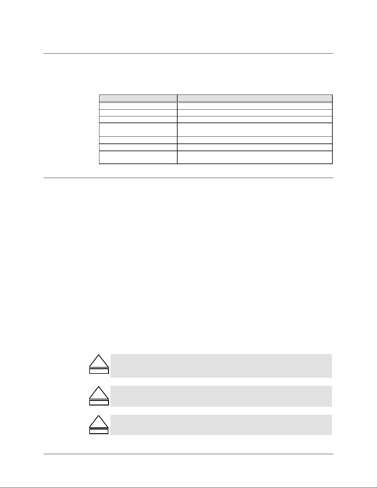
Revision Numbering Scheme
The following table identifies the revision numbering scheme utilized for EFData
installation and operation manuals, addenda, and supplements:
Part Number Description
MN/SMS758 Rev. 0 1st edition of the manual.
MN/SMS758 Rev. 1 1st revision of the manual.
MN/SMS758 Rev. 2 2nd revision of the manual.
MN/SMS758 Rev. 1
MN/SMS758 Rev. 2
MN/SMS758 Rev. 2
MN/SMS758 Rev. 3 3rd revision of the manual (it includes information from
SA
A
B
Supplement A to Rev. 1 of the manual. (The “S” in “SA”
designates “Supplement.”)
Addendum A to Rev. 2 of the manual.
Addendum B to Rev. 2 of the manual.
Addenda A and B).
Conventions Used in this Manual
Screen Output and Command Syntax
A distinctive type of font is used for screen output and command syntax, which looks
like this:
This line is in monospace font.
Notes
Note: This is the style for a note.
Cautions, Warnings, and Dangers
The international hazard alert signal is shown below. The signal word listed beneath the
symbol is changed to indicate the nature of the hazard. The terms, in increasing order of
seriousness, are CAUTION, WARNING, and DANGER.
CAUTION indicates a hazardous situation that, if not avoided, may result in
!
CAUTION
WARNING
minor or moderate injury. CAUTION may also be used to indicate other
unsafe practices or risks of property damage.
WARNING indicates a potentially hazardous situation that, if not avoided,
!
could result in death or serious injury.
DANGER indicates an imminent hazard that, if not avoided, will result in
!
DANGER
ii MN/SMS758 Rev. 3
death or serious injury.
Page 7

SMS-758 Modem Protection Switch Preface
Heading Hierarchy
Each section of this manual is structured according to the following heading hierarchy:
Level Heading Format
1 (Highest)
2
3
4 (Lowest)
Level Heading 1
Level Heading 2
Case Sensitivity
Unless stated otherwise, commands and arguments listed in this manual are not case
sensitive.
References Used in this Manual
Military Standards
References to “MIL-STD-118” apply to the 114A series (i.e., MIL-STD-118-114A),
which provides electrical and functional characteristics of the unbalanced and balanced
voltage digital interface circuits applicable to both long haul and tactical
communications. Specifically, these references apply to the MIL-STD-188-114A
electrical characteristics for a balanced voltage digital interface circuit, Type 1 generator,
for the full range of data rates.
Level Heading 3
Level Heading 4
For more information, refer to the following document:
• Department of Defense (DOD) MIL-STD-188-114A, “Electrical Characteristics
of Digital Interface Circuits.”
Trademarks
Product names mentioned in this manual may be trademarks or registered trademarks of
their respective companies and are hereby acknowledged.
MN/SMS758 Rev. 3 iii
Page 8

Preface SMS-758 Modem Protection Switch
Related Documents
The following documents are referenced in this manual:
• Department of Defense (DOD) MIL-STD-188-114A, “Electrical Characteristics
of Digital Interface Circuits.”
• EFData Specification SP/1891.
Reporting Comments or Suggestions Concerning this Manual
Comments and suggestions regarding the content and design of this manual will be
appreciated. To submit comments, please complete the Technical Publications Remarks
Form found at the end of this manual.
Returning a Product
To return an EFData (in-warranty and out-of-warranty) product for repair or
replacement:
1. Request a Return Material Authorization (RMA) number from the EFData
Customer Service Department.
Be prepared to supply the Customer Service representative with the model
number, serial number, and a description of the problem.
2. To ensure that the product is not damaged during shipping, pack the product in
its original shipping carton/packaging.
3. Ship the product back to EFData. (Shipping charges should be prepaid.)
For more information regarding the warranty policies, refer to the disclaimer page
located behind the title page.
Upgrading a Product
To receive product upgrade information (i.e., hardware and/or software), contact an
EFData Customer Service representative.
Product Training
To obtain product training information, contact an EFData Customer Service
Representative.
iv MN/SMS758 Rev. 3
Page 9

Table of Contents
CHAPTER 1. INTRODUCTION..................................................................................1–1
1.1 Scope............................................................................................................................................................. 1–1
1.2 Purpose and Function.................................................................................................................................. 1–1
1.3 Description ................................................................................................................................................... 1–2
1.4 Performance Specification........................................................................................................................ 1–10
CHAPTER 2. INSTALLATION...................................................................................2–1
2.1 Unpacking..................................................................................................................................................... 2–1
2.2 System Installation.......................................................................................................................................2–2
2.2.1 Switch Setup........................................................................................................................................... 2–2
2.2.2 Modem Setup......................................................................................................................................... 2–3
2.3 System Requirements.................................................................................................................................. 2–3
2.4 External Connections.................................................................................................................................. 2–4
2.4.1 Data I/O.................................................................................................................................................. 2–5
2.4.2 External RS485 and RS232 Interface (J1 and J2) .................................................................................. 2–6
2.4.3 Modem Control RS485.......................................................................................................................... 2–6
2.4.4 On-Line Status (J4, J5)........................................................................................................................... 2–7
2.4.5 Relay-Remote/Fault (J6)......................................................................................................................... 2–8
2.4.6 Downlink Inputs (J7 through J10, J12 through J15)............................................................................... 2–8
2.4.7 Back-up Demods (J11, J16)................................................................................................................... 2–9
2.4.8 Prime Mod Inputs (J18 through J25)...................................................................................................... 2–9
2.4.9 Back-up Mod Inputs (J26, J36).............................................................................................................. 2–9
2.4.10 Offline IF Outputs (J17, J27) ............................................................................................................... 2–9
2.4.11 IF Outputs (J28 through J35).............................................................................................................. 2–10
2.4.12 AC Power (J37, J38).......................................................................................................................... 2–10
2.4.13 DC Power (J37, J38).......................................................................................................................... 2–10
2.4.14 Ground (J37) ...................................................................................................................................... 2–10
MN/SMS758 Rev. 3 v
Page 10

Table of Contents SMS-758 Modem Protection Switch
CHAPTER 3. OPERATION........................................................................................3–1
3.1 Front Panel Description.............................................................................................................................. 3–1
3.1.1 LED Indicators....................................................................................................................................... 3–2
3.1.2 Keypad and LCD Display....................................................................................................................... 3–2
3.2 Switch Setup................................................................................................................................................. 3–6
3.2.1 System Setup.......................................................................................................................................... 3–6
3.2.1.1 Time and Date Menu.......................................................................................................................3–6
3.2.1.2 Downlink Option.............................................................................................................................3–7
3.2.1.3 Active Prime Modulators Menu...................................................................................................... 3–7
3.2.1.4 Active Prime Demodulators Menu.................................................................................................. 3–7
3.2.1.5 Active Backup Modulators Menu................................................................................................... 3–7
3.2.1.6 Active Backup Demodulators Menu............................................................................................... 3–7
3.2.1.7 Modem Addresses Menu................................................................................................................. 3–8
3.2.2 Modem Setup......................................................................................................................................... 3–8
3.2.2.1 Interface Type Menu....................................................................................................................... 3–9
3.2.2.2 Downlink Selection Menu............................................................................................................. 3–10
3.2.2.3 Modulator Priority Menu.............................................................................................................. 3–10
3.2.2.4 Demodulator Priority Menu.......................................................................................................... 3–10
3.2.2.5 Demodulator Delay ....................................................................................................................... 3–11
3.2.2.6 Modulator Delay........................................................................................................................... 3–11
3.2.3 Modem Configuration.......................................................................................................................... 3–12
3.2.3.1 Prime and Backup Modem Configuration..................................................................................... 3–12
3.2.3.2 Modem Configuration Menu......................................................................................................... 3–12
3.2.3.3 Modem Verification...................................................................................................................... 3–13
3.2.4 Faults.................................................................................................................................................... 3–13
3.2.4.1 Modulator Operation Fault............................................................................................................ 3–13
3.2.4.2 Demodulator Operation Fault....................................................................................................... 3–14
3.2.4.3 M:N Faults.................................................................................................................................... 3–14
3.2.4.4 Battery Faults................................................................................................................................ 3–14
3.2.5 Operational Modes............................................................................................................................... 3–15
3.2.5.1 Bypass Mode................................................................................................................................. 3–15
3.2.5.2 Auto Mode.................................................................................................................................... 3–15
3.2.5.3 Local Mode................................................................................................................................... 3–20
3.2.5.4 Remote Mode................................................................................................................................ 3–20
3.2.6 Status Menu.......................................................................................................................................... 3–21
CHAPTER 4. THEORY OF OPERATION..................................................................4–1
4.1 Monitor and Control................................................................................................................................... 4–1
4.1.1 Theory of Operation............................................................................................................................... 4–2
4.1.2 M&C Serial Interface............................................................................................................................. 4–2
4.1.3 Remote Baud Rate.................................................................................................................................. 4–3
4.1.4 Remote Address..................................................................................................................................... 4–3
4.1.5 External Remote Serial Interface Selection............................................................................................ 4–4
4.1.6 Battery.................................................................................................................................................... 4–4
4.1.7 Error Response Function........................................................................................................................ 4–4
4.1.8 External I/O Interrupt Arbitration...........................................................................................................4–5
vi MN/SMS758 Rev. 3
Page 11

SMS-758 Modem Protection Switch Table of Contents
4.2 Modem Control Interface Specification..................................................................................................... 4–5
4.3 Relay-Remote Interface Specification........................................................................................................ 4–6
4.3.1 Command Structure................................................................................................................................ 4–6
4.4 Fault Interface Specification....................................................................................................................... 4–9
4.4.1 Controller fault....................................................................................................................................... 4–9
4.4.2 M:N Fault............................................................................................................................................... 4–9
4.4.3 Demodulator Signal Fault..................................................................................................................... 4–10
4.5 Online Status Specification....................................................................................................................... 4–10
4.5.1 Modulator Online Status....................................................................................................................... 4–10
4.5.2 Demodulator Online Status.................................................................................................................. 4–10
4.6 Interface Switches...................................................................................................................................... 4–11
4.6.1 RS-422/449 and MIL-STD-188-114/RS-449 Interface Switch............................................................ 4–11
4.6.1.1 Specification ................................................................................................................................. 4–11
4.6.1.2 Connector Pinouts......................................................................................................................... 4–12
4.6.2 V.35 Interface Switch........................................................................................................................... 4–15
4.6.2.1 Specification ................................................................................................................................. 4–15
4.6.2.2 Connector Pinouts......................................................................................................................... 4–16
4.6.3 V.35/RS-232 Interface Switch.............................................................................................................. 4–19
4.6.3.1 Electrical Specifications................................................................................................................ 4–20
4.6.3.2 Connector Pinouts......................................................................................................................... 4–21
4.6.3.2.1 V.35 Option........................................................................................................................... 4–21
4.6.3.2.2 RS-232 Option....................................................................................................................... 4–22
4.6.4 DS-1 and G.703 Interface Switch......................................................................................................... 4–25
4.6.4.1 Specification ................................................................................................................................. 4–26
4.6.4.2 Connector Pinouts......................................................................................................................... 4–26
4.6.5 IDR Interface Switch............................................................................................................................ 4–29
4.6.5.1 Specification ................................................................................................................................. 4–30
4.6.5.2 Connector Pinouts......................................................................................................................... 4–30
4.6.6 2:N IDR Interface Switch (1877 and 1879).......................................................................................... 4–33
4.6.6.1 Specification ................................................................................................................................. 4–33
4.6.6.2 Operation ...................................................................................................................................... 4–34
4.6.6.3 Connector Pinouts......................................................................................................................... 4–34
4.6.7 2:N IBS/ASYNC Interface Switch (1694 and 1695)............................................................................ 4–38
4.6.7.1 Specification ................................................................................................................................. 4–38
4.6.7.2 Operation ...................................................................................................................................... 4–39
4.6.7.3 Connector Pinouts......................................................................................................................... 4–39
4.7 Address Decoder/Driver............................................................................................................................ 4–44
4.7.1 Specifications....................................................................................................................................... 4–44
4.7.2 Theory of Operation............................................................................................................................. 4–44
4.8 IF Switch Driver ........................................................................................................................................ 4–46
4.8.1 Specifications....................................................................................................................................... 4–46
4.8.2 Theory of Operation............................................................................................................................. 4–46
MN/SMS758 Rev. 3 vii
Page 12

Table of Contents SMS-758 Modem Protection Switch
4.9 IF Switch..................................................................................................................................................... 4–47
4.9.1 Specifications....................................................................................................................................... 4–47
4.9.2 Theory of Operation............................................................................................................................. 4–47
4.10 Online Telemetry..................................................................................................................................... 4–49
4.10.1 Specifications..................................................................................................................................... 4–49
4.10.2 Theory of Operation........................................................................................................................... 4–49
4.11 Power Supply ........................................................................................................................................... 4–51
4.11.1 Specifications..................................................................................................................................... 4–51
CHAPTER 5. MAINTENANCE...................................................................................5–1
5.1 Fault Descriptions........................................................................................................................................ 5–1
5.1.1 Modulator Operation Fault..................................................................................................................... 5–1
5.1.2 Demodulator Operation Fault................................................................................................................. 5–1
5.1.3 M:N Faults.............................................................................................................................................. 5–2
5.1.4 Battery Faults......................................................................................................................................... 5–2
5.2 Fault Isolation.............................................................................................................................................. 5–3
5.2.1 Modulator Operation.............................................................................................................................. 5–3
5.2.2 Demodulator Operation.......................................................................................................................... 5–4
5.2.3 M:N Operation ....................................................................................................................................... 5–5
5.2.4 Battery.................................................................................................................................................... 5–6
5.3 Module Replacement................................................................................................................................... 5–7
5.3.1 Power Supply......................................................................................................................................... 5–7
5.3.2 IF Switch................................................................................................................................................ 5–8
5.3.3 Switch Driver ......................................................................................................................................... 5–8
5.3.4 Address Decoder/Driver......................................................................................................................... 5–8
5.3.5 M&C ...................................................................................................................................................... 5–8
5.3.6 Online Telemetry.................................................................................................................................... 5–9
5.3.7 Interface Switches.................................................................................................................................. 5–9
5.4 Repacking for Shipment.............................................................................................................................. 5–9
5.4.1 Return Instructions................................................................................................................................. 5–9
5.4.2 Repacking Instructions........................................................................................................................... 5–9
APPENDIX A. REMOTE CONTROL OPERATION: MODEM SWITCH.................... A–1
A.1 General ........................................................................................................................................................A–1
A.2 Message Structure ......................................................................................................................................A–1
A.2.1 Start Character.......................................................................................................................................A–2
A.2.2 Device Address......................................................................................................................................A–2
A.2.3 Command/Responses.............................................................................................................................A–3
A.2.4 End Character........................................................................................................................................A–3
viii MN/SMS758 Rev. 3
Page 13

SMS-758 Modem Protection Switch Table of Contents
A.3 Configuration Commands/Responses .......................................................................................................A–4
A.3.1 Modulator Configuration Commands/Responses..................................................................................A–4
A.3.1.1 Prime Modulator Active.................................................................................................................A–4
A.3.1.2 BackupModulator Active...............................................................................................................A–4
A.3.2 Demodulator Configuration Commands/Responses..............................................................................A–4
A.3.2.1 Prime Demodulator Active.............................................................................................................A–4
A.3.2.2 Prime Demodulator Transponder...................................................................................................A–5
A.3.2.3 Backup Demodulator Active..........................................................................................................A–5
A.3.3 Modem Configuration Commands/Responses.......................................................................................A–5
A.3.3.1 Prime Modem Address...................................................................................................................A–5
A.3.3.2 Backup Modem Address................................................................................................................A–6
A.3.3.3 Prime Modem Interface Type.........................................................................................................A–6
A.3.3.4 Backup Modem Interface Type......................................................................................................A–6
A.3.3.5 Modem Priority..............................................................................................................................A–7
A.3.3.6 Modem Online Delay.....................................................................................................................A–7
A.3.4 Status Commands/Responses.................................................................................................................A–7
A.3.4.1 Configuration Status....................................................................................................................... A–7
A.3.4.1.1 Prime Modulator Configuration Status...................................................................................A–7
A.3.4.1.2 Backup Modulator Configuration Status ................................................................................A–8
A.3.4.1.3 Prime Demodulator Configuration Status...............................................................................A–8
A.3.4.1.4 Backup Demodulator Configuration Status............................................................................A–8
A.3.4.2 Modulator Status............................................................................................................................A–9
A.3.4.3 Demodulator Status........................................................................................................................A–9
A.3.4.4 Prime Modem Fault Status.............................................................................................................A–9
A.3.4.5 Backup Modem Fault Status ........................................................................................................A–10
A.3.4.6 Firmware Version Status.............................................................................................................. A–10
A.3.4.7 Equipment Type...........................................................................................................................A–10
A.3.5 Operational Commands.......................................................................................................................A–10
A.3.5.1 Time of Day.................................................................................................................................A–10
A.3.5.2 Date..............................................................................................................................................A–11
A.3.5.3 Mode Command...........................................................................................................................A–11
A.3.5.4 Set Backup Modem Online/Offline..............................................................................................A–11
A.3.5.5 Load Modem Configuration(s).....................................................................................................A–12
A.3.5.5.1 Load All Active Modems Configurations.............................................................................A–12
A.3.5.5.2 Load Prime Modem Configuration....................................................................................... A–12
A.3.5.5.3 Load Backup Modem Configuration ....................................................................................A–13
A.3.5.6 Verify Modem Configuration(s)...................................................................................................A–13
A.3.5.6.1 Verify All Active Modems Configurations...........................................................................A–13
A.3.5.6.2 Verify Prime Modem Configuration .....................................................................................A–14
A.3.5.6.3 Verify Backup Modem Configuration..................................................................................A–14
A.3.5.7 Operational Status Commands (Faults)........................................................................................A–14
A.3.5.7.1 Modulator Operational Faults Status....................................................................................A–14
A.3.5.7.2 Demodulator Operational Faults Status................................................................................A–14
A.3.5.7.3 M:N Switch Fault Status Summary.......................................................................................A–15
A.3.5.7.4 Missing Parameter Faults...................................................................................................... A–15
A.3.5.7.5 Bulk Consolidated Status Faults...........................................................................................A–16
A.3.5.8 Downlink Transponder Option.....................................................................................................A–21
MN/SMS758 Rev. 3 ix
Page 14

Table of Contents SMS-758 Modem Protection Switch
APPENDIX B. REMOTE CONTROL OPERATION: INDEPENDENT MOD/DEMODB–1
B.1 General.........................................................................................................................................................B–1
B.2 Message Structure.......................................................................................................................................B–1
B.2.1 Start Character.......................................................................................................................................B–2
B.2.2 Device Address......................................................................................................................................B–2
B.2.3 Command/Responses .............................................................................................................................B–3
B.2.4 End Character........................................................................................................................................B–3
B.3 Configuration Commands/Responses........................................................................................................B–4
B.3.1 Modulator Configuration Commands/Responses ..................................................................................B–4
B.3.1.1 Prime Modulator Active.................................................................................................................B–4
B.3.1.2 Prime Modulator Priority............................................................................................................... B–4
B.3.1.3 Prime Modulator Online Delay.......................................................................................... ............B–4
B.3.1.4 Backup Modulator Active..............................................................................................................B–5
B.3.2 Demodulator Configuration Commands/Responses ..............................................................................B–5
B.3.2.1 Prime Demodulator Active.............................................................................................................B–5
B.3.2.2 Prime Demodulator Priority...........................................................................................................B–5
B.3.2.3 Prime Demodulator Transponder...................................................................................................B–6
B.3.2.4 Prime Demodulator Online Delay..................................................................................................B–6
B.3.2.5 Backup Demodulator Active..........................................................................................................B–6
B.3.3 Modem Configuration Commands/Responses.......................................................................................B–7
B.3.3.1 Prime Modem Address...................................................................................................................B–7
B.3.3.2 Backup Modem Address................................................................................................................B–7
B.3.3.3 Prime Modem Interface Type.........................................................................................................B–7
B.3.3.4 Backup Modem Interface Type......................................................................................................B–8
B.3.4 Status Commands/Responses.................................................................................................................B–8
B.3.4.1 Configuration Status.......................................................................................................................B–8
B.3.4.1.1 Prime Modulator Configuration Status ...................................................................................B–8
B.3.4.1.2 Backup Modulator Configuration Status................................................................................. B–8
B.3.4.1.3 Prime Demodulator Configuration Status...............................................................................B–9
B.3.4.1.4 Backup Demodulator Configuration Status.............................................................................B–9
B.3.4.2 Modulator Status............................................................................................................................B–9
B.3.4.3 Demodulator Status......................................................................................................................B–10
B.3.4.4 Prime Modem Fault Status...........................................................................................................B–10
B.3.4.5 Backup Modem Fault Status........................................................................................................B–10
B.3.4.6 Firmware Version Status..............................................................................................................B–10
B.3.4.7 Equipment Type...........................................................................................................................B–11
B.3.5 Operational Commands .......................................................................................................................B–11
B.3.5.1 Time of Day.................................................................................................................................B–11
B.3.5.2 Date..............................................................................................................................................B–11
B.3.5.3 Mode Command...........................................................................................................................B–12
B.3.5.4 Set Backup Modulator Online/Offline.......................................................................................... B–12
B.3.5.5 Set Backup Demodulator Online/Offline .....................................................................................B–12
B.3.5.6 Load Modem Configuration(s)..................................................................................................... B–13
B.3.5.6.1 Load All Active Modems Configurations.............................................................................B–13
B.3.5.6.2 Load Prime Modem Configuration.......................................................................................B –13
B.3.5.6.3 Load Backup Modem Configuration.....................................................................................B–14
x MN/SMS758 Rev. 3
Page 15

SMS-758 Modem Protection Switch Table of Contents
B.3.5.7 Verify Modem Configuration(s)...................................................................................................B–14
B.3.5.7.1 Verify All Active Modems Configurations...........................................................................B–14
B.3.5.7.2 Verify Prime Modem Configuration.....................................................................................B–15
B.3.5.7.3 Verify Backup Modem Configuration ..................................................................................B–15
B.3.5.8 Operational Status Commands (Faults)........................................................................................B–15
B.3.5.8.1 Modulator Operational Faults Status ....................................................................................B–15
B.3.5.8.2 Demodulator Operational Faults Status................................................................................B–15
B.3.5.8.3 M:N Switch Fault Status Summary....................................................................................... B–16
B.3.5.8.4 Missing Parameter Faults......................................................................................................B–16
B.3.5.8.5 Bulk Consolidated Status Faults...........................................................................................B–17
B.3.5.9 Downlink Transponder Option.....................................................................................................B–22
APPENDIX C. 7 DOWNLINK OPTION..................................................................... C–1
C.1 External Connections .................................................................................................................................C–2
C.1.1 D/L Switch Input (J7) ............................................................................................................................C–2
C.1.2 D/L Switch Output (J16)........................................................................................................................C–2
C.1.3 Downlink Inputs (J8 through J10, J12 through J15) ..............................................................................C–3
C.1.4 Backup Demod (J11).............................................................................................................................C–3
C.2 Front Panel Operation ...............................................................................................................................C–3
MN/SMS758 Rev. 3 xi
Page 16

Table of Contents SMS-758 Modem Protection Switch
This page is intentionally left blank.
xii MN/SMS758 Rev. 3
Page 17

1.1 Scope
This manual describes the SMS-758 modem protection switch (Figure 1-1), hereafter
called “the switch.”
The switch is a rack-mounted unit that provides independent backup control for
modulators and demodulators, or simultaneous modulator and demodulator (modem)
switching.
If a primary modem element failure occurs, the switch limits the loss of communication.
1.2 Purpose and Function
Chapter 1.
INTRODUCTION
The switch is a fully automated, self-contained switching unit for many EFData satellite
data modems, including:
• SDM-650B
• SDM-308B
• SDM-309B
• SDM-8000
• SDM-100
• SLM-4650
• SLM-8650
The switch, with one or two backup modems, provides redundancy for up to eight
primary modems.
The switch will automatically or manually switch one of two backup modulators online
to take the place of any of eight primary modulators. Also, one of two backup
demodulators may be switched online to receive any one of four possible downlinks.
MN/SMS758 Rev. 3 1–1
Page 18

Introduction SMS-758 Modem Protection Switch
The switch does not contain an IF signal combining/dividing section, so that the user
may externally tailor each application for minimum loss. An example system
configuration using four prime modems is shown in Figure 1-6.
In normal operation, each prime modulator input is fed through to its corresponding IF
output, and the backup modulators are fed to the offline IF outputs. When a modulator
fault is detected, the faulted modulator is switched offline and re-routed to one of the
offline IF outputs. The next available backup modulator is configured identically to the
failed modulator, and is switched ON in its place.
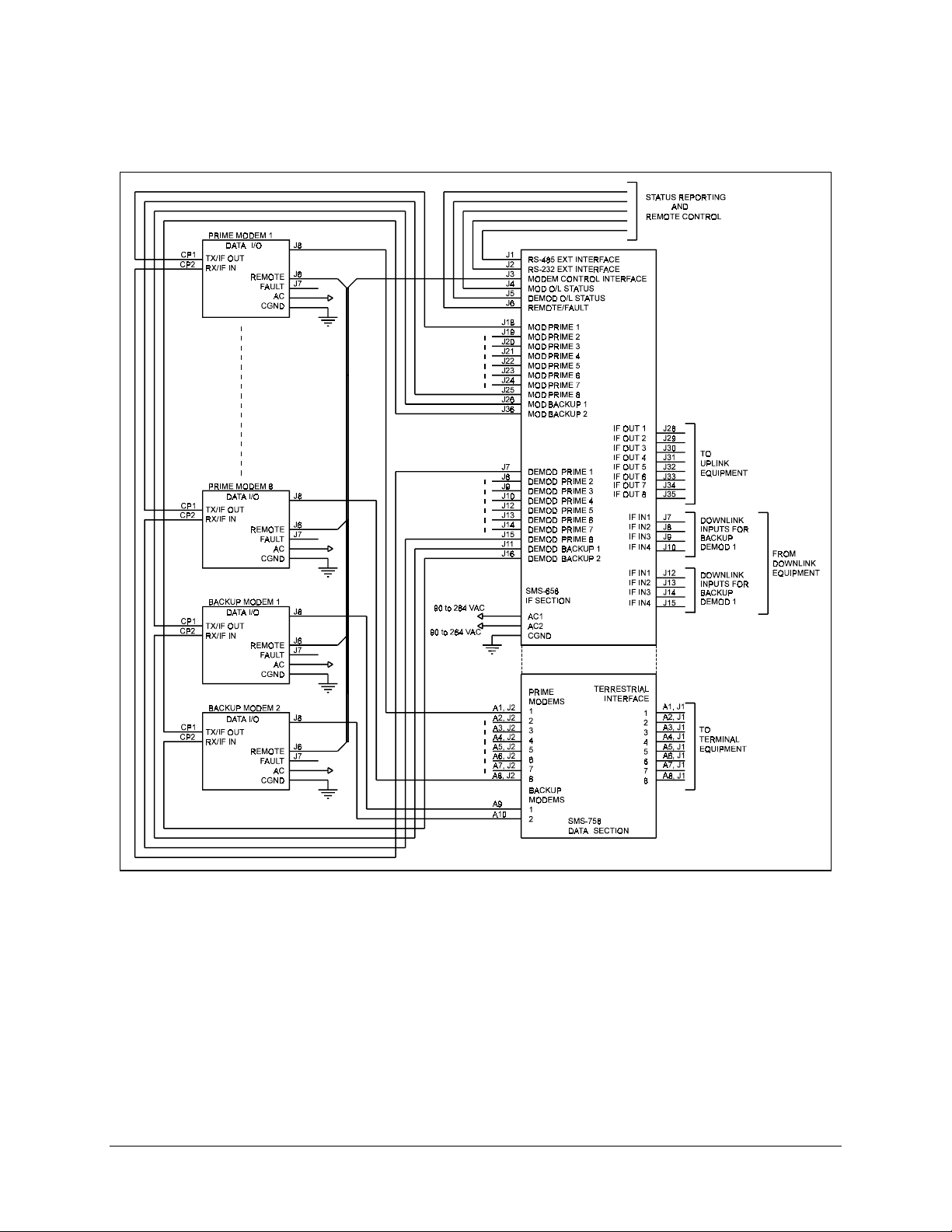
Figure 1-2 shows the switch interface between the prime and backup modems, the
terminal equipment, and IF converter equipment. The switch provides:
• All data and IF switching circuitry
• Complete status and fault reporting
The switch provides a high degree of flexibility by utilizing the multiple data rate feature
of the modems, and dual backups. Automatic configuration greatly reduces setup time.
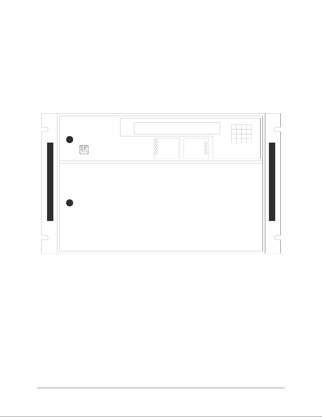
1.3 Description
The switch is complete and self contained, in a standard 19” rack-mountable enclosure
weighing approximately 50 lbs. It is of modular construction. The chassis assembly is
segmented with upper and lower chassis mounted backplanes.
The top section (Figure 1-3) contains:
The lower section contains:
The switch contains a microcontroller system. This system controls all switching
functions and maintains communication with the modems. It also communicates with an
optional external controller. A remote operator can control the switching by using a
terminal or computer, and the remote serial interface.
• Two power supplies providing redundancy in case of power failure, four printed
circuit board (PCB) assemblies, and the front panel keypad and display, which
are accessible from the front of the switch.
• Serial remote interfaces, relay-remote/fault, modulator and demodulator status,
and IF connections accessible from the rear panel. Figure 1-4 is a block diagram
of the IF switching matrix.
• An enclosed storage area, accessible from the front panel.
• The data switch interface modules, accessible from the rear.
1–2 MN/SMS758 Rev. 3
Page 19
SMS-758 Modem Protection Switch Introduction
Redundant power supplies maintain switch operation even if one power supply fails. The
switch and modem configurations are stored in battery-backed memory devices, for
protection against power loss.
A block diagram of the switch is shown in Figure 1-5.
SMS-758 MO DEM PRO TECTION
SWITCH SW1.00 PRESS NE XT
SMS-758
M:N SW ITC H
POWER
AUTO
LOCAL
REMOTE
BYPASS
BATTERY
DEMOD
FAULTSSTATUS
MOD
M:N
Figure 1-1. SMS-758 Modem Protection Switch
F1 8
7
F2
45
NXT
1
PRV
0
9
6
2
3
ENT
.
MN/SMS758 Rev. 3 1–3
Page 20
Introduction SMS-758 Modem Protection Switch
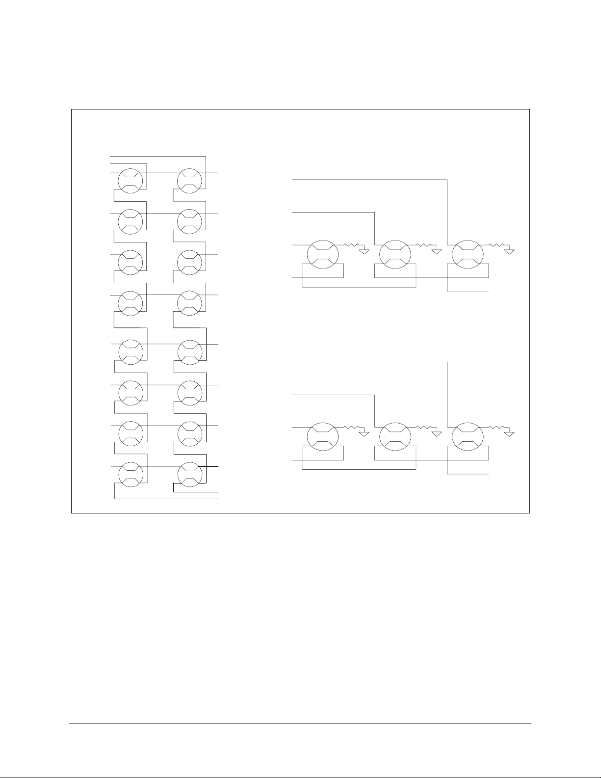
Figure 1-2. System Block Diagram
1–4 MN/SMS758 Rev. 3
Page 21
SMS-758 Modem Protection Switch Introduction
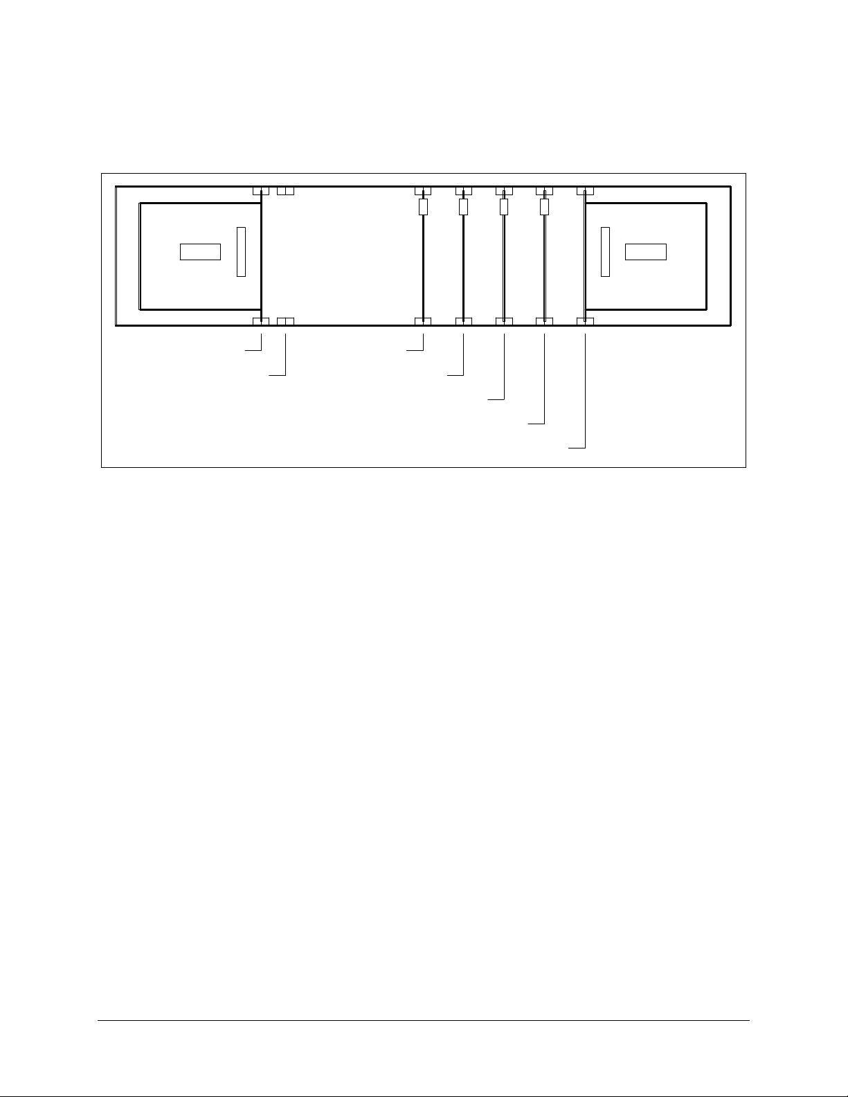
SLOT 1
POWER SUPPLY
NOT USED
SLOT 3
SWITCH DRIVER
SLOT 2
SLOT 4
ADDRESS DEC/DRV
SLOT 5
MONITOR AND CONTROL
SLOT 6
ONLINE TELEMETRY
POWER SUPPLY 2
SLOT 7
Figure 1-3. SMS-758 Upper Front Section Interior
MN/SMS758 Rev. 3 1–5
Page 22
Introduction SMS-758 Modem Protection Switch
UTS
INPUTS
BU MOD 2
BU MOD 1
MOD 1
MOD 2
MOD 3
MOD 4
MOD 5
MOD 6
MODULATOR SWITCH
OUTPUTS
IF 1
IF 2
IF 3
IF 4
IF 5
IF 6
DEMODULATOR SWITCH
INP
DOWNLINK 4
DOWNLINK 3
DOWNLINK 2
DOWNLINK 1
BACKUP DEMOD 1
INPUTS
DOWNLINK 4
DOWNLINK 3
MOD 7
MOD 8
IF 7
IF 8
BACKUP 2 IF OUTPUT
BACKUP 1 IF OUTPUT
DOWNLINK 2
DOWNLINK 1
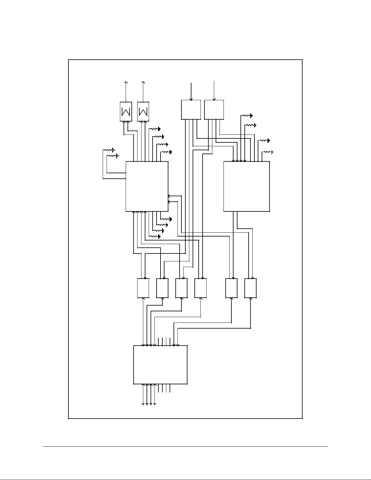
Figure 1-4. SMS-758 IF Switching Matrix
BACKUP DEMOD 2
1–6 MN/SMS758 Rev. 3
Page 23
SMS-758 Modem Protection Switch Introduction
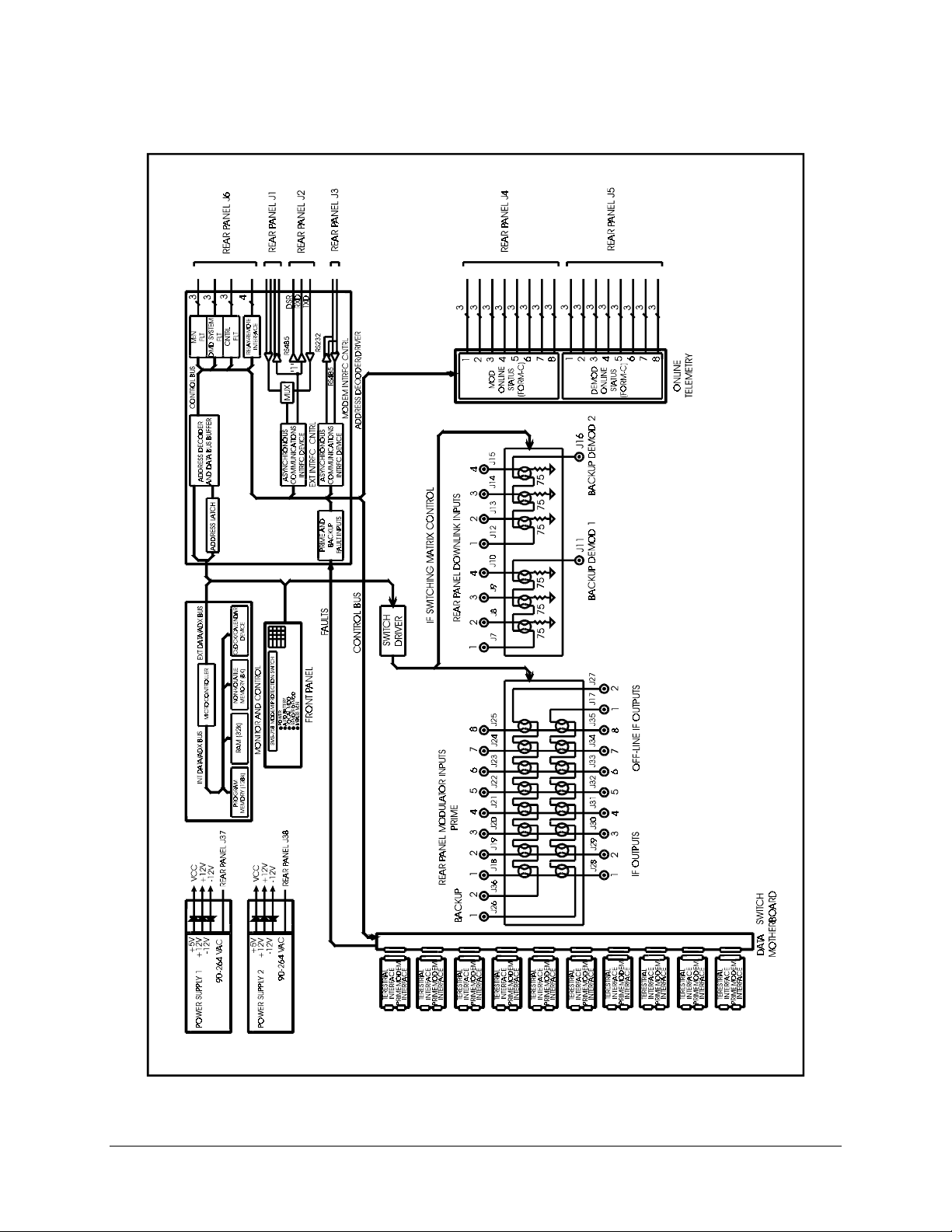
Figure 1-5. SMS-758 Block Diagram
MN/SMS758 Rev. 3 1–7
Page 24
Introduction SMS-758 Modem Protection Switch
UPLINK 1
UPLINK 2
DOWNLINK 1
DOWNLINK 2
1:6
SPLITTER
75
75
75
75
75
12345
J28
J29
J30
OFF-LINE
IF OUTPUTS
J17 J27
J31
IF
SMS-758
MODULATOR
J18
J19
J20
J21
12345
75
6
7
8
J32
J33
J34
J35
INPUTS
SWITCH
J22
J23
J24
6
7
75
BACKUP MOD
12
J26 J36
J25
8
75
75
75
1:6
SPLITTER
INPUTS
DOWNLINK
BACKUP
DEMODS
DL1
J7
J11
1
DL2
J8
SMS-758
J16
2
75
75
75
75
DL3J9
DL1
DL2
DL3
DL4
DL4
J12
J13
J14
J10
J15
IF
DEMOD
SWITCH
PRIME MOD INPUTS IF OUTPUTS
MUST BE TERMINATED INTO 75 OHMS.
TX IF
RX IF
TX IF
RX IF
TX IF
RX IF
TX IF
1
PRIME MODEMS
J2J2J2
A1A2A3
INPUTS
2
J2
J2J2J2
A4
A5A6A7A8A9
3
J2
A10
RX IF
4
TX IF
RX IF
TX IF
1
BACKUP MODEMS
RX IF
2
NOTE: ALL UNUSED IF SWITCHING CONNECTIONS
PRIME MODEM
DATA
SWITCH
SMS-758
A5A6A7
A4
J1
J1J1J1
A8
J1
TERR DATA
A1A2A3
J1J1J1
TERMINAL
EQUIPMENT
Figure 1-6. Example System Configuration
1–8 MN/SMS758 Rev. 3
Page 25

SMS-758 Modem Protection Switch Introduction
The switch consists of the following assemblies:
Assembly D escription Drawing No.
Chassis AS/1890
Controller Motherboard AS/1317
Data Switch Motherboard AS/1349
Monitor and Control AS/0356
Address Decoder/Driver AS/1048
Switch Driver AS/1316
IF Switch AS/1314
O/L Telemetry AS/0585
Display/Keypad AS/0540
Power Supply (2 each) AS/0584
DS-1 Prime Interface Switch AS/0893 8 Optional
DS-1 Backup Interface Switch AS/0894 2 Optional
V.35 Prime Interface Switch AS/0891 8 Optional
V.35 Backup Interface Switch AS/0892 2 Optional
RS-422 Prime Interface Switch AS/0890 8 Optional
RS-422 Backup Interface Switch AS/0899 2 Optional
IDR Prime Interface Switch (1:N) AS/0895 8 Optional
IDR Backup Interface Switch (1:N) AS/0896 1 Optional
IDR 45MB Prime Interface Switch AS/0936 8 Optional
IBS/ASYNC Prime Interface Switch AS/1695 8 Optional
IBS/ASYNC Backup Interface Switch AS/1694 2 Optional
IDR Prime Interface Switch (2:N) AS/1877-1 8 Optional
IDR Backup Interface Switch (2:N) AS/1879 2 Optional
Drop & Insert daisy chain Interface Switch AS/1877-2 9 Optional
MN/SMS758 Rev. 3 1–9
Page 26

Introduction SMS-758 Modem Protection Switch
1.4 Performance Specification
The operating specifications of the switch are described in Table 1-1.
Table 1-1. SMS-758 Performance Specification
Operation
Number of Online Modems Expandable from 1 to 8 with plug-in prime
interface switch modules (the modems can be
of different data rates and interfaces, as long
as the backup modems are compatible).
Number of Backup Modems Expandable from 1 to 2 with plug-in backup
interface switch modules (IDR AS/0895
interface limits the backup to one).
Data Interfaces DS-1 and G.703, V.35, RS-422/449/
MIL-STD-188-114, IBS, IDR, or D&I.
IF Frequency Response 50 MHz to 180 MHz .
Downlinks Each demodulator is configurable for 1 of 4 or
7 downlink connections.
Uplinks Eight modulator outputs may be externally
combined/divided for any number of uplinks.
Prime Modulator to Output Loss Less than 1 dB.
Backup Modulator to Prime Output Loss Less than 1 dB.
Manual Delay Switch-Over T ime:
Modulator
Demodulator
Auto Delay Switch-Over Time:
Modulator
Demodulator
Switch-Over Priority One of three priority levels av ailable
Remote Control Interfaces:
External control
Modem Control
Batteries M&C: NiCad, 30 day memory retention.
0 to 127.5 sec., in 0.5 sec. steps.
0 to 127.5 sec., in 0.5 sec. steps.
< 1 sec.
< 3 sweep periods of the back-up
demodulator.
independently for each modulator and
demodulator, if independent mod/demod
firmware is used. Modulators and
demodulators will switch simultaneously with
modem switch firmware.
RS-485 or RS-232C. Baud rates from 110 to
9600, Even or Odd parity, Addresses from
1 to 255.
RS-485, Baud rate 9600, Even parity,
Addresses from 1 to 255.
48 hr. charge time.
1–10 MN/SMS758 Rev. 3
Page 27

SMS-758 Modem Protection Switch Introduction
Indicators:
Front Panel LEDs
48-character display
Alarm Reporting:
Controller Fault Alarm
System Fault Alarm
Demodulator Fault Alarm
Operational Modes Auto, Local, Remote, and Bypass.
Controls Complete control of all M:N functions from the
Input Voltage 90 to 264 VAC (self-adjusting).
Line Power 40W maximum when both power supplies are
Line Frequency 47 to 63 Hz.
Size 19" W x 22" D x 12.20" H.
Weight 50 lbs.
Power supply on, controller and power supply
alarm, demodulator system failure, modulator
system failure, low battery alarm, auto mode,
local mode, remote mode, and bypass mode.
Prime and backup modulator and
demodulator status (fault and online status),
active modulators and demodulators (prime
and backup), modem address, modem
interface, modem uplink and downlink,
priority, delay, configuration, and fault menus.
Form C relay contact to indicate controller or
power supply failure.
Form C relay contact to indicate any non-
catastrophic failure.
Form C relay contact to indicate all
demodulators faulted and a probable IF loss.
front panel, or through the remote interface.
General
-48 VDC optional.
operating.
MN/SMS758 Rev. 3 1–11
Page 28

Introduction SMS-758 Modem Protection Switch
This page is intentionally left blank.
1–12 MN/SMS758 Rev. 3
Page 29
This chapter consists of:
CAUTION
2.1 Unpacking
The switch and manual are packaged in pre-formed, reusable, cardboard cartons
containing foam spacing for maximum shipping protection. To remove the switch:
Chapter 2.
INSTALLATION
• Unpacking instructions
• System installation
• System requirements
• Description of the external connections
The equipment contains parts and assemblies sensitive to damage by
!
Electrostatic Discharge (ESD). Use ESD precautionary procedures when
touching, removing, or inserting printed circuit boards.
Do not use any cutting tool that will extend more than 1” into the container
!
CAUTION
MN/SMS758 Rev. 3 2–1
and cause damage to the modem.
1. Cut the tape at the top of the carton (indicated by OPEN THIS END).
2. Remove the cardboard/foam space covering the switch.
3. Remove the switch, manual, and power cord from carton.
4. Save the packing material for storage or reshipment purposes.
5. Inspect the equipment for any possible damage incurred during shipment.
6. Check the equipment against the packing list to ensure the shipment is correct.
7. Refer to Section 2.2 for further system installation instructions.
Page 30

Installation SMS-758 Modem Protection Switch
2.2 System Installation
2.2.1 Switch Setup
After unpacking, refer to the following steps to install the switch:
1. Mount the switch chassis in the assigned position of the equipment rack. It is
recommended that the switch be supported by a rack-mounted shelf.
2. Be sure that all interface switch modules are in their proper positions, and are
fully seated in the rear backplane.
3. Connect the cables to the proper locations on the rear panel. Refer to Section 2.4
for connector pinouts, placement, and function.
4. Open the front panel and verify that the two power supplies and four circuit
modules are properly seated in the upper backplane.
5. Before turning the power switch ON, become familiar with front panel operation
in Chapter 3.
6. Turn ON each power supply, located inside the front panel. The power switch is
ON when the switch is depressed toward the “1”, or when the red side of the
switch is exposed.
7. Close the front panel, and configure the switch as described in Section 3.2. Place
the switch in the proper mode for operation.
8. If any installation problems occur, refer to Chapter 5 for troubleshooting the
system.
2–2 MN/SMS758 Rev. 3
Page 31

SMS-758 Modem Protection Switch Installation
2.2.2 Modem Setup
J28 through J35 are the eight IF outputs available to connect to the customer-supplied
uplink power combiners.
J7 through J10, and J12 through J15, are the downlink inputs available for use with up to
eight customer-supplied downlink splitters. The following steps describe the uplink and
downlink connections:
1. Connect the IF output cables 1 through 8 to the appropriate customer-furnished
uplink signal combiner inputs.
2. Connect the downlink input cables 1 through 4, or 1 through 7, to the appropriate
customer-furnished downlink splitters.
3. When using the 7 downlink option, connect J16 (backup 2 output) to J7, and
specify 7 downlinks/1 backup in the System menu.
Note: Be sure to terminate all unused IF outputs and downlink inputs with the
supplied 75
2.3 System Requirements
The switch, with all interface assemblies installed (Figure 2-1), is capable of operating as
a 2:8 protection switch. This means that two full-duplex standby modems back up eight
full-duplex primary modems.
Note: When IDR interface AS/0895 is used, only one backup is available.
The switch can be configured in any combination including:
• TX only modems.
• RX only modems.
• Mixed interfaces (limited to two).
• Multiple uplinks (limited to eight).
• Multiple downlinks (limited to four with 2 backups, 7 with 1 backup).
• Multiple data rate and code rate operation.
• Refer to Section 3.2 for a complete explanation of the configuration function.
BNC terminations.
Ω
MN/SMS758 Rev. 3 2–3
Page 32

Installation SMS-758 Modem Protection Switch
2.4 External Connections
All connections between the switch and other equipment are made through rear panel
connections. Table 2-1 lists these connectors, and Figure 2-1 shows the locations. The
uses of these connectors are described in the following sections.
D/L
SW
IN
1
2
5
DOWN
LINK
INPUTS
6
7
OUT
3
4
D/L
SW
J12
J13
FOR SEVEN DOWNLINK
J14
J15
J16J11
OPERATION
J10
J7
J8
J9
BU
DMD
OUT
RS485
RS232
RS485
90-264 VAC
A1
EXTERNAL
J1
J2
MODEM
CONTROL
J3
J37
J7
INPUTSJ8
J9
J10
BACK-UP
1
DEMODS
J11
A2 A3
1
2
DOWN
LINK
3
4
1
J12
2
J13
3
J14
4
J15
2
J16
A4
PRIME INTERFACE
SWITCH MODULES
A5
1
J17
OFF-LINE
IF OUTPUTS
J27
2
Figure 2-1. SMS-758 Rear Panel
123
J28 J29 J30
MOD
ON-LINE STATUS
J4
A6 A7
J20J19J18
321
PRIME MOD INPUTS
IF OUTPUTS
456
J31 J32
DEMOD
ON-LINE STATUS
J5 J6
J22J21
REMOTE/FAULT
A8
J23
J24
654
78
J33 J34 J35
J38
BACKUP INTERFACE
SWITCH MODULES
J39
J25
87
BACKUP
MOD INP UTS
A10A9
GND
1
J26
J36
2
2–4 MN/SMS758 Rev. 3
Page 33

SMS-758 Modem Protection Switch Installation
Table 2-1. Rear Panel Connections
Name Ref. Desig. Connector Function
DATA I/O A1 - A10
J1, J2
EXTERNAL
RS485
RS232
MODEM
CONTROL RS485
ON-LINE STATUS J4 and J5 25-Pin D Mod and Demod Online Status
REMOTE/FAULT S J6 25-Pin D Relay/Remote and Faults
DOWNLINK
INPUTS
BACK-UP
DEMODS
PRIME MOD
INPUTS
BACK-UP MOD
INPUTS
OFF-LINE IF
OUTPUTS
IF OUTPUTS J28 through J35 BNC IF Outputs to Uplinks
AC POWER J37, J38 CEE22 AC Power Input
DC POWER J37, J38 Terminal
GROUND J39 #10-32 Stud Chassis Ground
J1
J2
J3 9-Pin D Remote Interface
J7 through J10,
J12 through J15
J11 through J16 BNC Downlink Outputs to Backup
J18 through J25 BNC Modulator IF Inputs
J26 and J36 BNC Backup Mod IF Inputs
J17 and J27 BNC Offline Mod IF O utputs
37-Pin D
34-Pin Block
15-Pin D
37-Pin D
50-Pin D
50-Pin D
9-Pin D
9-Pin D
BNC Downlink IF Inputs
Block
RS-422/449 and
MIL-STD-188-114 I/O
V.35 I/O
DS-1 and G.703 I/O
DCTN I/O
IDR I/O
IBS I/O
Remote Interface
Reporting
Demods
48 VDC Power Input
Note: All unused BNC connectors must have a 75
termination.
Ω
2.4.1 Data I/O
Connect the Modem and Terrestrial Data I/O to the plug-in interface switch modules in
the lower rear section of the switch. The interface switch module slots are designated A1
through A10 (left to right, viewed from the rear). A1 through A8 are slots for prime
interface switch modules 1 through 8. A9 and A10 are backup module slots 1 and 2.
Prime interface switch modules have two connectors: J1 on the top connects to terrestrial
equipment; J2 on the bottom connects to the prime modem. (See Note below.) Backup
interface switch modules have one connector, J1, for backup modem connection. Refer
to Section 4.3 for electrical specifications, and data pin-outs.
Note: For the RS-422/449/MIL-STD-188-114 interface switch modules: J1 on the left
connects to the prime modem, and J2 on the right connects to the terrestrial equipment.
MN/SMS758 Rev. 3 2–5
Page 34

Installation SMS-758 Modem Protection Switch
2.4.2 External RS485 and RS232 Interface (J1 and J2)
The external interface connectors provide serial remote interface to the switch. An
external controller can connect through J1 (RS-485) or J2 (RS-232C).
Use M&C module switch pack SP1 switch 5 (SP1-5) to configure each switch for
external remote interface type, either RS-485 or RS-232C. The ON position (nearer the
PCB) selects RS-232C interface, and OFF selects RS-485.
The external interface connectors are 9-pin female D connectors with screw locks for
mechanical security. The remote connector is a DCE interface.
RS-485 RS-232C
Pin Number Name Pin Number Name
1GND1
2 2 RD (RX)
33TD (TX)
4+RX/TX4
5RX/TX5GND
66
77
8+RX/TX8
9-RX/TX9
2.4.3 Modem Control RS485
The prime and backup modems connect to the switch through J3, the modem control
interface connector. This connector provides the bus-type control interface required for
system operation.
Refer to Sections 4.2.2, 4.2.3, and the remote specifications (Appendixes A and B) for a
complete explanation of the remote interface functions.
Refer to the RS-485 pinout listed in Section 2.4.2
2–6 MN/SMS758 Rev. 3
Page 35

SMS-758 Modem Protection Switch Installation
2.4.4 On-Line Status (J4, J5)
Connectors J4 and J5 provide the output for the modulator and demodulator backup
online status in form C format:
• J4 is for the modulator online status.
• J5 is for the demodulator online status.
Refer to Section 4.1.7 for a complete explanation of the online status functions.
Two 25-pin female D connectors interface with the online status reporting sections.
Screw locks provide mechanical security for the mating connector.
ON-LINE STATUS INTERFACE
J4
Pin #
1 Mod 1 COM Demod 1 COM
2 Mod 1 NC Demod 1 NC
3 Mod 1 NO Demod 1 NO
4 Mod 2 COM Demod 2 COM
5 Mod 2 NC Demod 2 NC
6 Mod 2 NO Demod 2 NO
7 Mod 3 COM Demod 3 COM
8 Mod 3 NC Demod 3 NC
9 Mod 3 NO Demod 3 NO
10 Mod 4 COM Demod 4 COM
11 Mod 4 NC Demod 4 NC
12 Mod 4 NO Demod 4 N O
13 Mod 5 COM Demod 5 COM
14 Mod 5 NC Demod 5 NC
15 Mod 5 NO Demod 5 N O
16 Mod 6 COM Demod 6 COM
17 Mod 6 NC Demod 6 NC
18 Mod 6 NO Demod 6 N O
19 Mod 7 COM Demod 7 COM
20 Mod 7 NC Demod 7 NC
21 Mod 7 NO Demod 7 N O
22 Mod 8 COM Demod 8 COM
23 Mod 8 NC Demod 8 NC
24 Mod 8 NO Demod 8 N O
25 GROUND GROUND
Name
J5
Name
MN/SMS758 Rev. 3 2–7
Page 36

Installation SMS-758 Modem Protection Switch
2.4.5 Relay-Remote/Fault (J6)
This 25 pin connector provides both input and output signals. The inputs are contact
closures or logic-level remote control inputs. The outputs are form C relay contact
closures for controller fault, M:N fault, and demodulator system fault.
Refer to Sections 3.2.4, 3.2.5, and 4.3 for more information on the relay-remote and fault
functions.
The relay-remote input and fault status interface connects through a 25-pin female D
connector. Screw locks provide mechanical security for the mating connector.
Relay-Remote Input and Fault Output Interface
Pin No. Name
1 Controller Fault COM
2 Controller Fault NC
3 Controller Fault NO
4 Relay-Remote Input 0
5 Relay-Remote Input 1
6 Relay-Remote Input 2
7 Relay-Remote Input 3
8 Demodulator Fault COM
9 Demodulator Fault NC
10 Demodulator Fault NO
11 M:N Fault COM
12 M:N Fault NC
13 M:N Fault NO
14 through 24 No Connection
25 Ground
2.4.6 Downlink Inputs (J7 through J10, J12 through J15)
These are the downlink input connectors. These connections provide the inputs to the
downlink switching matrix:
• J7 through J10 are the inputs to backup modem 1.
• J12 through J15 are the inputs to backup modem 2, when the switch is
configured for 4 downlinks/2 backups.
Up to seven downlinks can be connected to the switch in the 7 downlink/1 backup
configuration. This option is available in the System menu on the front panel.
Downlink inputs that are not being used must be terminated into 75
Refer to Appendix C for more information on the 7 downlink/1 backup option.
2–8 MN/SMS758 Rev. 3
Ω.
Page 37

SMS-758 Modem Protection Switch Installation
2.4.7 Back-up Demods (J11, J16)
J11 and J16 provide the outputs from the downlink switching matrix. J11 is the backup
demod 1 output, and J16 is the backup demod 2 output. They connect to the backup
modem’s RX IF inputs.
Any of the 4 downlinks can be directed internally to J11 and J16. The default setting is
downlink 1.
The input frequency range is 50 to 180 MHz, with an input impedance of 75
Terminate any back-up demod port into 75
2.4.8 Prime Mod Inputs (J18 through J25)
J18 through J25 are the prime modulator IF input connections to the Modulator IF
switching matrix. They connect to the prime modem IF outputs.
The input frequency range is 50 to 180 MHz, with an input impedance of 75
Prime mod inputs that are not being used must be terminated into 75
2.4.9 Back-up Mod Inputs (J26, J36)
J26 and J36 are the backup modulator IF input connectors. They connect to the backup
modem IF outputs.
The input frequency range is 50 to 180 MHz, with an input impedance of 75
2.4.10 Offline IF Outputs (J17, J27)
when not being used.
Ω
.
Ω
.
Ω
.
Ω
.
Ω
The offline IF output connectors, J17 and J27 are used as a monitor and test point:
• The outputs of the backup modulators are routed here when not in use.
• When backups are online, the offline primes are routed here.
MN/SMS758 Rev. 3 2–9
Page 38

Installation SMS-758 Modem Protection Switch
2.4.11 IF Outputs (J28 through J35)
J28 through J35 are the modulator IF switching matrix output connections. They connect
to the external uplink power combiners. Up to 8 uplinks can be connected to the switch,
or as few as 1.
During normal operation, the prime modulator IF outputs are switched here. During a
fault condition, the backup modulator’s IF output will be switched here.
The frequency range is 50 to 180 MHz, with an output impedance of 75
output power level is equal to the modem TX output level, which is from -5 dBm to
-30 dBm.
Any IF outputs that are not being used must be terminated into 75
2.4.12 AC Power (J37, J38)
Two independent, non-locking, 3-prong power cords connect AC power to the two power
supplies.
Normal input voltage is 90 to 264 VAC (self-adjusting) at 47 to 63 Hz. Maximum power
consumption is 40W.
It is recommended that each power supply be plugged into a different power source, to
provide continuous power to the switch if one source fails.
2.4.13 DC Power (J37, J38)
Two terminal blocks are provided for optional -48 VDC (± 4.8V) power supplies.
Customer supplied power wires should be fitted with standard #6 screw lugs.
. The typical
Ω
.
Ω
Maximum power consumption is 40W.
It is recommended that each power supply be plugged into a different power source, to
provide continuous power to the switch if one source fails.
Note: Applying incorrect input voltage to these connectors can cause severe damage to
the switch and will void the product warranty. Verify that the source voltage is correct
before connecting the switch.
2.4.14 Ground (J37)
A #10-32 stud is available on the rear panel for connecting the chassis to ground.
2–10 MN/SMS758 Rev. 3
Page 39

3.1 Front Panel Description
The switch front panel (Figure 3-1) provides the local interface to configure, operate, and
monitor the switch:
• A 48-character, 2-line LCD display in the upper-front panel displays options and
status for the operator.
• Nine LEDs grouped under the LCD display provide mode and fault status at a
glance.
• A 16-key keypad to the right allows the operator to perform setup, configuration,
and operation functions.
Chapter 3.
OPERATION
• An audible beeper signals the pressing of a keypad key.
The display, LEDs, and beeper are mapped into address space of the external bus
structure. The display updates every second, and the LEDs and beeper update as needed.
SMS-758
M:N SWI TCH
SMS-758 MODEM P R OTECTION
SWIT CH SWX.XX PRESS NEXT
POWER
AUTO
LOCAL
REMOTE
BYPASS
STATUS
BATTERY
DEMOD
FAULTS
MOD
M:N
F1
F2
NEXT
PREV
9
8
7
4
6
5
2
3
1
0
ENT
.
Figure 3-1. SMS-758 Front Panel
MN/SMS758 Rev. 3 3–1
Page 40

Operation SMS-758 Modem Protection Switch
Any keypad activity provides an interrupt to the processor, which then scans the keypad.
After the input has been recognized, the processor takes the appropriate action.
All switch functions are accessible to the operator from the front panel through the [F1]
and [F2] keys, the [PREV] key, and the [NEXT] key.
Proper operation of the switch depends on its proper configuration and setup. The
following sections describe the front panel and its operation in detail.
3.1.1 LED Indicators
Nine LEDs on the front panel indicate the general switch status and summary fault
information, as follows:
Faults
M:N Red LED Lights if M:N fault condition occurs.
MOD Red LED Lights if a modulator operation fault occurs.
DEMOD Red LED Lights if demodulator operation fault occurs.
BATTERY Red LED Lights if the M&C battery voltage is low.
POWER ON Green LED Lights when power is applied to the switch.
AUTO Green LED Lights when the switch is in the automatic operating mode.
LOCAL Green LED Lights when the switch is in the local operating mode.
REMOTE Green LED Lights when the switch is in the remote operating mode.
BYPASS Green LED Lights when the switch is in the bypass operating mode.
3.1.2 Keypad and LCD Display
The keypad and LCD display provide an interface for the local operator to access the
menus that configure and operate the switch. The keypad includes the following keys:
• Numbers 0 through 9
• Decimal
• [ENT] key
• [F1] and [F2] keys
• [NEXT] and [PREV] keys
The [F1], [F2], [NEXT], and [PREV] keys control the hierarchical menu structure.
Menus provide for local setup, configuration, and operation.
Each menu contains a portion of the switch control, or setup algorithm.
Status
Only a limited knowledge of the switch is required, as the menus are self-prompting, and
all options are displayed.
3–2 MN/SMS758 Rev. 3
Page 41

SMS-758 Modem Protection Switch Operation
The base levels of this tree-structured front panel menu are as follows:
• ID menu displayed at power-on
• SYSTEM and MODEM SETUP menu
• CONFIGURATION and VERIFICATION menu
• FAULT menu
• MODE menu
• STATUS display
The ID menu displays the model number of the switch and version of firmware installed.
The [NEXT], [PREV], [F1], [F2], and [ENT] keys control the menus, and allow menu
selections.
Some display messages have menu options on the right side, aligned with the [F1] and
[F2] keys. Pressing either of those keys directs the display to the selected menu.
The operator can move forward or backward through the selected menu by pressing the
[NEXT] or [PREV] keys.
The switch beeps in response to keypad inputs:
• One beep acknowledges a valid entry, with the appropriate action being taken.
• Two beeps indicate that the entry was invalid, and no action was taken.
Once the correct menu is selected, the operator can press the [ENT] key to enter, change,
or view the functions within that menu.
Refer to Figure 3-2 for details of the menu hierarchy and display s.
The display maps show the menus available with independant mod/demod firmware
installed (version 6.x.x). Modem switching firmware (version 5.x.x) has slight
differences in the “Modem Setup” and “Local Mode” menus.
In the “Modem Setup” menu:
• The “Select Interface” menu with the options 7, 8, and 9 does not exist.
• “Mod Priority” and “Demod Priority” are conbined into “Modem Priority.”
• “Demod Delay” and “Mod Delay” are combined into “Modem Delay.”
In the “Local Mode” menu,
• The “Select Mod or Demod” menu does not exist.
MN/SMS758 Rev. 3 3–3
Page 42

Operation SMS-758 Modem Protection Switch
Figure 3-2. SMS-758 Display Map (Sheet 1 of 2)
3–4 MN/SMS758 Rev. 3
Page 43

SMS-758 Modem Protection Switch Operation
Figure 3-2. SMS-758 Display Map (Sheet 2 of 2)
MN/SMS758 Rev. 3 3–5
Page 44

Operation SMS-758 Modem Protection Switch
3.2 Switch Setup
3.2.1 System Setup
Enter the SYSTEM SETUP menu to enter, change, or view the system setup
configuration. The definitions of the system setup functions are as follows:
TIME AND DATE Time and date are entered and displayed.
DOWNLINK OPTION Downlink options are entered and displayed. (Refer to Appendix C.)
PRIME MODS Active prime modulators are selected and displayed.
PRIME DEMODS Active prime demodulators are selected and displayed.
BACKUP MODS Active backup modulators are selected and displayed.
BACKUP DEMODS Active backup demodulators are selected and displayed.
MODEM ADDRESSES Prime and backup modem addresses are selected and displayed.
In the SYSTEM SETUP menu, the operator views system configuration parameters by
using the [NEXT] and [PREV] keys. The operator can also enter data or change a
parameter through keypad entries.
When all data or changes for that parameter are entered correctly, press [ENT] to load
the information into memory.
After [ENT] is pressed, the display will increment to show the next available menu. If an
incorrect entry is made, press [PREV] to return to that menu, and re-enter the data.
The following sections describe each parameter in detail.
3.2.1.1 Time and Date Menu
This menu displays the current time and date. The operator can enter the time by
pressing [F1] and following the format:
HH MM
[F1] should then be pressed to select AM, or [F2] for PM.
When [ENT] is pressed, seconds reset to 0, and the new time loads into the clock device.
The operator can enter the date by pressing [F2] and following the format:
MM DD YY
Pressing [ENT] loads the new date into the clock device.
3–6 MN/SMS758 Rev. 3
Page 45

SMS-758 Modem Protection Switch Operation
3.2.1.2 Downlink Option
This menu displays the current downlink option, showing how many downlinks and
backups are selected.
The operator may choose from four downlinks with two backups possible, or seven
downlinks and only one backup. Pressing any number key will toggle the two options,
and pressing [ENT] will load the displayed choice into memory.
Refer to Appendix C for more information about the 7 downlink/1 backup option.
3.2.1.3 Active Prime Modulators Menu
This menu displays the current prime modulators that are active in the system. Pressing
the keys [1] through [8] will toggle the active status (ON/OFF) of the corresponding
modulator only. Modulators with numbers displayed are active. Pressing [ENT] loads
that information into memory.
3.2.1.4 Active Prime Demodulators Menu
This menu displays the current prime demodulators that are active in the system.
Pressing the keys [1] through [8] will toggle the active status of the corresponding
demodulator only. Demodulators with numbers displayed are active. Pressing [ENT]
loads that information into memory.
3.2.1.5 Active Backup Modulators Menu
This menu displays the current backup modulators that are active in the system. Pressing
the keys [1] or [2] will toggle the active status of the corresponding backup modulator
only. Modulators with numbers displayed are active. Pressing [ENT] loads that
information into memory.
3.2.1.6 Active Backup Demodulators Menu
This menu displays the current backup demodulators that are active in the system.
Pressing the keys [1] or [2] will toggle the active status of the corresponding backup
demodulator only. Demodulators with numbers displayed are active. Pressing [ENT]
loads that information into memory.
MN/SMS758 Rev. 3 3–7
Page 46

Operation SMS-758 Modem Protection Switch
3.2.1.7 Modem Addresses Menu
This menu displays the current addresses of the prime and backup modems, and channel
units, if applicable. Addresses of 1 through 255 are valid. Entering a new address and
pressing [ENT] loads the address into memory. If no address is entered for an active
modem, an M:N fault results.
Never use the global address “0”. The configurations of the prime modems
!
CAUTION
Note: Pressing [ENT] while in this menu will increment the prime modem number,
while [NEXT] will transfer the user out of that address subsection to the next menu.
For example, after assigning address 2 to prime modem 2 and pressing [ENT], an address
may be assigned to prime modem 3. Pressing [NEXT] then will allow the user to skip
prime modems 3 through 8, and go directly to the backup modem menu, and assign an
address to backup modem 1.
may become corrupted.
3.2.2 Modem Setup
To enter, change, or view the modem setup configuration, enter the MODEM SETUP
menu by pressing F2. The MODEM SETUP functions are as follows:
INTERFACE Interface type is selected and displayed for each modem.
DOWNLINK Downlink assignment (1 through 4, or 1 through 7) is selected and
MOD PRIORITY The prime modulator priorities are selected and displayed.
DEMOD PRIORIT Y The prime demodulator priorities are selected and displayed.
DEMOD DELAY The prime demodulator online delay is selected and displayed.
MOD DELAY The prime modulator online delay is selected and displayed.
Note: When using modem switch firmware, mod and demod priorities are combined into
modem priority, and mod and demod delays are combined into modem delay, since the
mod and demod switch simultaneously.
In the MODEM SETUP menu, the operator can select prime or backup modems by
pressing [F1] or [F2]. It is recommended that the prime modems be configured first,
since the switch increments the number of the prime modem displayed as each previous
set of parameters is entered.
For example, after configuring prime modem 1, the switch will ask for the configuration
for prime modem 2, etc.
displayed for demodulators. (Refer to Appendix C.)
3–8 MN/SMS758 Rev. 3
Page 47

SMS-758 Modem Protection Switch Operation
The operator can view the modem configuration parameters by using the [NEXT] and
[PREV] keys. A flashing cursor will be displayed over the selected parameter. To enter
data or change a parameter, the operator uses the keypad to enter the data. When all data
or changes for that parameter are correct, press [ENT] to load the information into
memory. The following sections describe each parameter in detail.
Note: [ENT] or [NEXT] may be used to get from one frame to the next in this menu, but
only [ENT] will enter data.
3.2.2.1 Interface Type Menu
This menu displays the current interface type for each prime and backup modem.
Selections 1 through 9 are labeled:
Screen 1 1. 15D (For both DS-1 and G.703 interfaces)
2. V.35
3. RS449 (For both RS-422/449 and M IL-ST D -188-114/R S-449 interfaces)
Screen 2 4. DCTN (Modified RS-422 interface)
5. IDR (for 1:N AS/0895)
6. OTHER
Screen 3 7. IBS
8. D&I (for “loomed” D&I systems. Read paragraph below.)
9. IDR 2:N (for 2:N AS/1877)
The operator enters the number associated with the interface type, and presses [ENT] to
load the selected interface information into memory. Selections may only be made from
the displayed options. If no interface type is entered for an active modem, an M:N fault
results.
The OTHER interface type applies to ASYNC interfaces (AS/1695), or installations with
dual 1:4 systems, or similar configurations having identical interfaces. Normally, the
switch treats the two 1:4 systems with the same interface type as a single 2:8, but when
OTHER interface type is selected for one of the 1:4 systems, the switch considers the
interfaces different, and treats each 1:4 system as a separate system.
The “loomed” D&I system requires special firmware in the switch, special switch
interfaces (AS/2152), additional breakout panels, and special cabling. The advantage of
the “loomed” system is that during switching, there is no interruption of the data stream
(T1 or E1). The only data that is affected is the data of the failed unit.
Note: Interface type is the only setup parameter for backup modems.
Note: Although the last three options do not exist with modem switch firmware, IBS and
IDR 2:N can be chosen by selecting option 6 (OTHER).
MN/SMS758 Rev. 3 3–9
Page 48

Operation SMS-758 Modem Protection Switch
3.2.2.2 Downlink Selection Menu
This menu displays the current downlink number (1 through 4, or 1 through 7) for each
demodulator. When the operator enters the number of the downlink selected and presses
[ENT], that information is loaded into memory. If no downlink is selected for an active
demodulator, an M:N fault results.
Note: Hardware connections for uplink and downlink must be identical to the setup
selection. Any difference causes erroneous switch operation.
Refer to Appendix C for more information about the 7 downlink/1 backup option.
3.2.2.3 Modulator Priority Menu
This menu displays the current priority level for this prime modulator.
• “1” indicates high priority.
• “2” indicates medium priority.
• “3” indicates low priority.
When the operator enters “1”, “2”, or “3” and presses [ENT], the information is loaded
into memory. If nothing is entered, the priority will be low.
The backup algorithm uses priority levels to make backup decisions. When a backup
modulator is online for a faulted prime with a lower priority than a newly faulted
modulator, that backup modem becomes available for use to backup the newly faulted
unit having the higher priority.
3.2.2.4 Demodulator Priority Menu
This menu displays the current priority level for this prime demodulator.
• “1” indicates high priority.
• “2” indicates medium priority.
• “3” indicates low priority.
When the operator enters “1”, “2”, or “3” and presses [ENT], the information is loaded
into memory. If nothing is entered, the priority will be low.
The backup algorithm uses priority levels to make backup decisions. When a backup
demodulator is online for a faulted prime with a lower priority than a newly faulted
prime, that backup modem becomes available for use to backup the newly faulted unit
having the higher priority.
3–10 MN/SMS758 Rev. 3
Page 49

SMS-758 Modem Protection Switch Operation
3.2.2.5 Demodulator Delay
This menu displays the current online delay for this prime demodulator, and allows the
operator to enter a new parameter. The DEMOD DELAY is the time allowed for the
prime demodulator to clear its faulted state. At the end of this delay, if the prime is no
longer faulted, it will be restored to online status. If the prime is still faulted, the backup
demodulator is committed to that channel and will be unavailable for any other faulted
prime having the same or lower priority.
The operator selects “1”, “2”, or “3”:
• “1” for no time delay.
• “2” for manual.
• “3” for automatic delay selection (2 times the sweep period).
Entering “1” or “3” and pressing [ENT] loads the information into memory. Entering “2”
and pressing [ENT] allows the operator to enter from 0 to 127.5 seconds, in 0.5 second
increments. When [ENT] is pressed again, the delay data is loaded into memory.
If nothing is entered, the switch automatically defaults to “3” (automatic).
3.2.2.6 Modulator Delay
The Modulator Delay menu displays the current online delay for this prime modulator,
and allows the operator to enter a new parameter. The MOD DELAY is the time allowed
for the prime modulator to clear its faulted state. At the end of this delay, if the prime is
no longer faulted, it is restored to online status. If the prime is still faulted, the backup
modulator is committed to that channel, and will be unavailable for any other faulted
prime having the same or lower priority.
The operator selects “1” or “2”:
• “1” for no time delay.
• “2” for manual.
Entering “1” and pressing [ENT] loads the information into memory. Entering “2” and
pressing [ENT] allows the operator to enter from 0 to 127.5 seconds, in 0.5 second
increments. When [ENT] is pressed again, the delay data is loaded into memory.
If nothing is entered, the switch defaults to 1 (none).
Note: In certain applications, the MOD/DEMOD DELAY and PRIORITY settings are
replaced by MODEM DELAY and PRIORITY settings. This occurs when modem switch
firmware is used instead of independent mod/demod.
MN/SMS758 Rev. 3 3–11
Page 50

Operation SMS-758 Modem Protection Switch
3.2.3 Modem Configuration
3.2.3.1 Prime and Backup Modem Configuration
The operator must be sure that the prime modems have all parameters properly
configured for operation prior to configuration loading or verifying. The only required
parameters for a backup modem are the data rate and code rate assignments in the
modem’s utility menu.
To communicate with the modems, the switch must have the modem addresses entered
into the system configuration. The serial interface type, baud rate, and parity of the
switch modem control interface is fixed, and therefore cannot be programmed by the
operator. For interface information, refer to Section 4.1.5.
The modems must be set to RS-485 interface, 9600 baud, and even parity. Each modem
in the switch system must have its own unique address. The interface type, baud rate,
parity, and addresses are selected on the M&C card in the modem. (See the appropriate
section of the modem installation and operation manual.)
3.2.3.2 Modem Configuration Menu
To load the modem configurations, press [F1] (LOAD) in the MODEM
CONFIGURATION menu, and proceed as follows:
1. To load the configuration of an individual prime or backup modem, use the [F1]
(SELECT) menu. If [F1] (SELECT) is pressed, the menu presents options of
PRIME (F1) and BACKUP (F2). After the selection of prime or backup, the last
menu will require entry of the prime or backup modem number. The switch
automatically loads the configuration of the modem selected.
2. To load the configuration of all active modems, use the [F2] (ALL) menu. If [F2]
(ALL) is pressed, the menu requires that [ENT] be pressed to begin the loading
of all active modem configurations.
The switch displays “OK” or “ERROR”, showing the result of the configuration loading
process. An “ERROR” response results in an M:N fault.
3–12 MN/SMS758 Rev. 3
Page 51

SMS-758 Modem Protection Switch Operation
3.2.3.3 Modem Verification
To verify the modem configurations, press [F2] (VERIFY) in the MODEM
CONFIGURATION menu, and proceed as follows:
1. To verify the configuration of an individual prime or backup modem, use the
[F1] (SELECT) menu. If F1 (SELECT) is pressed, the menu presents options of
PRIME (F1) and BACKUP (F2). After the selection of prime or backup, the last
menu will require entry of the prime or backup modem number. The switch
automatically verifies the configuration of the modem selected.
2. To verify the configuration of all the active modems, use the [F2] (ALL) menu.
If F2 (ALL) is pressed, the menu requires that [ENT] be pressed to begin the
verifying of all active modem configurations.
The switch displays “OK” or “ERROR”, showing the result of the configuration loading
process. An “ERROR” response results in an M:N fault.
3.2.4 Faults
Note: When any change is made in the prime or backup modem configuration, the
operator must reload that modem’s configuration into the switch. If this is not done, a
configuration verify error will be flagged in the M:N fault menu.
When any fault LED(s) is lighted, an operational fault condition exists. However, LEDs
are only a summary visual alarm. The operator should use the FAULT menu to
determine the exact cause of the fault and takes remedial action, if necessary.
The FAULT menu provides fault information. Use the [1], [2], [3], [4], [NEXT], and
[PREV] keys to reveal the nature of any fault indicated by a front panel red LED.
The following sections list all possible fault messages that could appear in each category.
Refer to Section 5.2 for a list of possible causes, and for the fault isolation procedures.
3.2.4.1 Modulator Operation Fault
The fault menu displays MOD fault(s) when a modulator backup switching operation
failure occurs. The messages will be as follows:
BK-UP FAULT MOD X
(Where: X = 1 to 8.)
MN/SMS758 Rev. 3 3–13
Page 52

Operation SMS-758 Modem Protection Switch
3.2.4.2 Demodulator Operation Fault
The fault menu displays DEMOD fault(s) when a demodulator backup switching
operation failure occurs. The messages will be either of the following:
BK-UP FAULT DMD X
(Where: X = 1 to 8.)
ALL DMDS D/L X FAULTED
(Where: X = 1 to 7.)
3.2.4.3 M:N Faults
The fault menu displays M:N fault(s) when a communication, configuration, setup,
and/or power supply failure occurs. The messages will be any of the following:
MODEM X COMM FAILURE
MODEM BX COMM FAILURE
CONFIG VERIFY ERROR M (or D) X
CONFIG VERIFY ERROR BM (or BD) X
BK-UP M (or D) X NOT COMPATIBLE
PRIME M (or D) X NOT COMPATIBLE
NO ADDRESS FOR PRIME X
NO ADDRESS FOR BK-UP X
NO INTERFACE FOR PRIME X
NO INTERFACE FOR BK-UP X
NO D/L FOR DMD X
NO CONFIG FOR PRIME M (or D) X
NO CONFIG FOR BK-UP M (or D) X
(Where X = 1 to 8.)
(Where X = 1 to 2.)
(Where X = 1 to 8.)
(Where X = 1 to 2.)
(Where X = 1 to 2.)
(Where X = 1 to 8.)
(Where X = 1 to 8.)
(Where X = 1 to 2.)
(Where X = 1 to 8.)
(Where X = 1 to 2.)
(Where X = 1 to 8.)
(Where X = 1 to 8.)
(Where X = 1 to 2.)
+12V FAILURE
-12V FAILURE
+5V FAILURE
POWER SUPPLY 1 FAULT
POWER SUPPLY 2 FAULT
3.2.4.4 Battery Faults
The fault menu displays a BATTERY fault when an M&C battery failure (low voltage)
occurs in the switch. The message will be as follows:
M&C BATTERY FAULT
3–14 MN/SMS758 Rev. 3
Page 53

SMS-758 Modem Protection Switch Operation
3.2.5 Operational Modes
The MODE menu selects the mode of operation. At power-up, the switch defaults to the
BYPASS mode unless:
• It was in a different mode prior to loss of power.
• The battery-backed memory was maintained.
The following modes of operation are available:
BYPASS All switching is halted. No change will take place until the switch is returned to
the AUTO, LOCAL, or REM OTE mode. No interruptions will occur in the data
flow of any modem already backed-up as a result of changing modes.
AUTOMATI C The M&C controls all switching.
LOCAL The on-site operator controls all switching.
REMOTE In REMOTE mode, all sw itching is controlled by a remote controller v ia the
remote interface. The on-site operator cannot select this mode of operation.
3.2.5.1 Bypass Mode
The BYPASS mode is recommended for configuration functions. It is the default
operating mode at power-up, if the switch was not programmed for a different mode
prior to loss of power, or if the battery-backed memory was not maintained. The switch
is not capable of performing any switching functions in the BYPASS mode. All
configuration and communication functions continue to operate, but no new backup
operation can take place. Any backup operation performed prior to selecting BYPASS
will remain in effect.
To enter the BYPASS mode, press [3] + [ENT] while in the MODE menu.
3.2.5.2 Auto Mode
The AUTO mode is the normal operating mode for the switch. Refer to the flowcharts in
Figures 3-3 and 3-4. If the switch was in this mode when power loss occurred, it will
return to this mode when power is restored. All previous backup status will be lost, but if
there are faults present when power is restored, the switch will backup those faulted
modulators and/or demodulators accordingly. Because the switch is communicating with
the prime and backup modems in this mode, response to keypad input and remote
communication may be delayed.
To enter the AUTO mode, press [1] + [ENT] while in the MODE menu.
MN/SMS758 Rev. 3 3–15
Page 54

Operation SMS-758 Modem Protection Switch
In the AUTO mode, the switch monitors the prime and backup modulator and
demodulator fault inputs, awaiting a failure. When no faults are present, the switch will
place the backup modulator(s) and demodulator(s) in the “Hot Standby” mode for the
highest priority prime(s), and a dash (-) will be displayed in the status display. In this
mode, the switch programs the backup modulator(s) and demodulator(s) for the highest
priority, lowest numbered prime modulator(s) and demodulator(s), and connects the
downlink IF to the backup demodulator(s). This action prepares the backup modulator(s)
and demodulator(s) for a minimal delay during the backing up of high priority channels.
When a fault does occur, the switch takes action according to the backup algorithm. The
backup algorithm selects the highest priority, lowest numbered faulted channel for
backup, and will take a lower priority channel backup offline, even if that channel is still
faulted, to back up a higher priority channel.
When a demodulator backup is required, the switch performs the following steps:
1. It verifies the configuration of the backup demodulator, and re-programs it, if
necessary.
2. If more than one demodulator is faulted, the switch selects the demodulator with
the highest priority. If more than one faulted demodulator is set to the highest
priority, the switch selects the demodulator with the lowest channel number.
3. The switch implements the sweep delay (it is not programmable by the user).
This delay is two times the sweep period of the demodulator. At the end of the
sweep delay or when the backup demodulator locks, the switch performs one of
the following operations:
a. If the backup demodulator fails to lock, the switch makes the back-up
demodulator available for other faulted channels.
b. If the backup demodulator locks, the switch commits the backup
demodulator to the faulted prime and starts the demodulator delay timer. An
asterisk (*) will be displayed in the status display if modem switch firmware
is installed. (Continue to Step 4.)
4. At the end of the demodulator delay, the switch again checks the fault status of
the prime demodulator.
a. If the prime demodulator still shows a fault, the switch places the backup
demodulator online for the faulted prime, and an arrow will be displayed in
the status display. The backup will then be available only to failed primes
having higher priority.
b. If the prime demodulator locks during the demodulator delay, the backup
demodulator is made available for other faulted primes.
3–16 MN/SMS758 Rev. 3
Page 55

SMS-758 Modem Protection Switch Operation
When a modulator backup is required, the switch performs the following steps:
1. It verifies the configuration of the backup modulator and re-programs it, if
necessary.
2. If more than one modulator is faulted, the switch selects the modulator with the
highest priority. If two or more faulted modulators are set to the highest priority,
the switch selects the modulator with the lowest channel number.
3. It implements a 500 millisecond delay (not programmable by the user). At the
end of the delay, the switch performs one of the following operations:
a. If the prime modulator is not faulted, the switch makes the backup modulator
available for other faulted channels.
b. If the backup modulator is not faulted, and the prime remains faulted, the
switch commits the backup modulator to the faulted prime, and starts the
modulator delay timer. An asterisk (*) is displayed in the status display if
modem switch firmware is used. (Continue to Step 4.)
4. At the end of the modulator delay, the switch again checks the fault status of the
prime modulator.
a. If the prime modulator is still faulted, the switch places the backup
modulator online for the faulted prime, and an arrow is displayed in the
status display. The backup is then available only to failed primes having
higher priority.
b. If the prime modulator clears its fault during the modulator delay, the prime
modulator is restored to service. The backup modulator is made available for
other faulted primes.
When a modem backup is required, the switch performs both demodulator and modulator
procedures simultaneously. However, the switch will not place the backup modem online
until the backup demodulator locks and the modem online delay timer times-out.
The switch continually verifies the configurations of all active modulators and
demodulators. If the switch fails to verify any configuration, an M:N fault results.
Changing from any mode to another mode (including AUTO) does not change the
backup status unless a new fault occurs.
MN/SMS758 Rev. 3 3–17
Page 56

Operation SMS-758 Modem Protection Switch
DEMOD AUTO MODE
YES
HAS THE
VERIFY TIMER
TIMED OUT?
NO
ARE ANY
PRIMES
FLT’D?
YES
ARE THE
FLT’D
PRIMES
B/U’D?
NO
PUT FLT’D
PRIMES IN PRIORITY
ORDER. START WITH
HIGHEST PRIORITY.
IS THIS
FLT’D
PRIME B/U’D?
NO
IS A
B/U
AVAILABLE?
YES
IS
THE B/U
ON STAND-BY
FOR THIS
PRIME?
YES
VERIFY B/U
CONFIGURATION.
UPDATE IF
NECESSARY.
(SERIAL REMOTE
NOT AVAILABLE)
YES
OF THE NEXT DMD.
NO
PROGRAM B/U (s)
FOR HIGHES T
PRIORITY CHANNEL( s).
(SERIAL REMOTE NOT
AVAILABLE)
YES
NO
PRIOIRTY PRIME
NO
CONFIGURATION
FOR THIS PRIME.
(SERIAL REMOTE
NOT AVAILABLE)
VERIFY THE
CONFIGURATION
(SERIAL REMOTE
NOT AVAILABLE)
ARE THE
B/U (s) ON
STAND-BY?
NO
IS A
LOWER
B/U’D?
YES
PROGRAM B/U
WITH THE
NO
YES
PLACE B/U (s ) IN
STAND-BY MODE.
INDICATE WITH “-” ON
FRONT PANEL
IS A
NON-FLT’D
PRIME B/U’D?
NO
YES
WAIT FOR ALL
YES
NO
APPLICABLE TIMERS.
NO
YES
FLT’D PRIME IN THE
YES
INDICATE PRIME
WITH “#” ON
FRONT PANEL
GO TO NEXT
PRIORITY ORDER.
ARE ALL
PRIME DMDS
FLT’D?
SET THE DMD
OPERATION FLT.
(FRONT PANEL
LEDS.)
NO
YES
IS THE
PRIME STILL
FLT’D?
YES
PLACE B/U ON - LINE
FOR FLT’D PRIME.
INDICATED PRIME
WITH “->“ ON
FRONT PANEL.
SET ALL DMDS
FLT’D FLT. (BACK
PANEL RELAY)
NO
IS THE
B/U DMD
FLT’D?
NO
HAS THE
SWEEP TIMER
TIMED OUT?
YES
ARE
OTHER
PRIMES
FLT’D?
ARE
NO
ANY
FLT’D PRIMES
NOT B/U’D?
Figure 3-3. SMS-758 Switching Algorithm Flow Chart
(Demodulator and Modem)
3–18 MN/SMS758 Rev. 3
Page 57

SMS-758 Modem Protection Switch Operation
MOD AUTO MODE
YES
NO
HAS THE
VERIFY TIMER
TIMED OUT?
NO
ARE ANY
PRIMES
FLT’D?
YES
ARE THE
FLT’D
PRIMES
B/U’D?
NO
PUT FLT’D
PRIMES IN PRIORITY
ORDER. START WITH
HIGHEST PRIORITY.
IS THIS
FLT’D
PRIME B/U’D?
NO
IS A
B/U
AVAILABLE?
YES
IS
THE B/U
ON STAND-BY
FOR THIS
PRIME?
YES
VERIFY B/U
CONFIGURATION.
UPDATE IF
NECESSARY.
(SERIAL REMOTE
NOT AVAILABLE)
YES
OF THE NEXT MOD.
NO
PROGRAM B/U (s)
FOR HIGH ES T
PRIORITY CHANNEL(s).
(SERIAL REMOTE NOT
AVAILABLE)
YES
NO
PRIOIRTY PRIME
NO
PROGRAM B/U
CONFIGURATION
FOR THIS PRIME.
(SERIAL REMOTE
NOT AVAILABLE)
VERIFY THE
CONFIGURATION
(SERIAL REMOTE
NOT AVAILABLE)
ARE THE
B/U (s) ON
STAND-BY?
NO
IS A
LOWER
B/U’D?
YES
WITH THE
NO
YES
PLACE B/U (s) IN
STAND-BY MODE.
INDICATE WITH “-” ON
FRONT PANEL
IS A
NON-FLT’D
PRIME B/U’D?
NO
YES
WAIT FOR ALL
APPLICABLE TIMERS.
NO
YES
FLT’D PRIME IN THE
INDICATE PRIME
WITH “#” ON
FRONT PANEL
GO TO NEXT
PRIORITY ORDER.
IS THE
PRIME STILL
FLT’D?
YES
PLACE B/U ON-LINE
FOR FLT’D PRIM E
WITH “->“ ON
FRONT PANEL.
NO
HAS
THE ONLINE
DELAY TIMER
TIMED OUT
YES
NO
IS THE
B/U MOD
FLT’D?
YES
HAS
THE 500 ms
TIMER TIMED
OUT?
YES
ARE
OTHER
PRIMES
FLT’D?
NO
Figure 3-4. SMS-758 Switching Algorithm Flow Chart (Modulator)
MN/SMS758 Rev. 3 3–19
Page 58

Operation SMS-758 Modem Protection Switch
3.2.5.3 Local Mode
In this operating mode, the switch responds to keypad input affecting setup,
configuration, fault inquiries, and backup online status. If the switch is in this mode
when power loss occurs, it will return to this mode when power is restored. However, the
current backup status will be lost. This mode can also be used for configuration
functions.
To enter the LOCAL mode, press [2] + [ENT] while in the MODE menu.
To change the backup status from local mode, proceed as follows:
1. Press [F1] or [F2] to select modulator or demodulator. (If the switch is a modem
switch rather than an independent modulator/demodulator switch, press [ENT] to
continue.)
2. Select the backup modem number (“1” or “2”), and press [ENT].
3. Select the prime modem number from 0 to 8. (“0” takes the backup modulator or
demodulator offline. “1” to “8” selects that prime for backup.) Press [ENT].
The switch performs the selected function and displays the online and fault status. When
the switch is in LOCAL mode, exercise care when changing the online status. The switch
performs the selected function regardless of fault status or modulator and demodulator
compatibility.
3.2.5.4 Remote Mode
In this operating mode, the switch responds to serial remote interface or relay-remote
input. The switch can receive a full range of commands from the serial remote interface
user, and a limited number from the relay-remote interface. If the switch was in this
mode prior to loss of power, it returns to this mode when power is restored. However,
current backup status will be lost.
This mode can be entered only from the serial remote interface or relay-remote interface.
For details of the Remote Interface Specification, refer to Sections 4.2 and 4.3, and
Appendixes A and B.
3–20 MN/SMS758 Rev. 3
Page 59

SMS-758 Modem Protection Switch Operation
3.2.6 Status Menu
The STATUS display follows the MODE menu. It provides the following inform ation:
• I dentifies the activ e modulators and demodulators, both prime and backup.
• Shows backup online status.
• Shows the fault status of all active prime and backup modulators and
demodulators.
The STATUS menu displays only the active modulators and dem odulators. If any
modulator or demodulator is faulted, an “F” alternates with the modem number on the
display.
The display shows online backup modulators and demodulators, with an arrow pointing to
the number of the prime being back ed- up.
“Hot Standby” mode is identified by a dash between the backup modulator/demodulator
and the prime modulator/demodulator.
An asterisk is displayed while the backup modulator/demodulator is in the process of
backing up a prime m odulator/dem odulator if modem switch firmware is installed (5.x.x).
In all modes except BYPA SS , the STATUS display returns after approximately three
minutes without keypad activity .
Refer to Figure 3-2 for details of the menu hierarchy and display s.
MN/SMS758 Rev. 3 3–21
Page 60

Operation SMS-758 Modem Protection Switch
This page is intentionally left blank.
3–22 MN/SMS758 Rev. 3
Page 61

THEORY OF OPERATION
4.1 Monitor and Control
A sophisticated microcontroller performs the monitor and control functions of the
switch. The module, called the “Monitor and Control” (M&C), plugs into slot 5 of the
switch chassis (refer to Figure 4-1 for a drawing of the M&C, and Figure 1-3 for the
location in the chassis).
The M&C gathers status and provides extensive fault monitoring. The M&C monitors
the switch configuration and updates other modules within the switch, as required.
Switch configuration parameters are stored in battery-backed RAM to provide total
recovery after a power-down.
A local front panel interface and a remote communications interface provide user access
to all switch functions.
Chapter 4.
SWITCH PACK (SP1)
PARITY AND BAUD RATE
SWITCH PACK (SP2)
ADDRESS
Figure 4-1. Monitor and Control
MN/SMS758 Rev. 3 4–1
JUMPERS JP1 THROUGH JPX
Page 62

Theory of Operation SMS-758 Modem Protection Switch
4.1.1 Theory of Operation
The M&C module uses an Intel 80C31 microcontroller operating at 5.5295 MHz.
The microsystem supports:
• 128K bytes of Read-Only Memory (ROM) for code.
• 64K bytes of Random-Access Memory (RAM) for data.
Of the 64K bytes, only 8K is used for RAM, and the remaining 56K is used for memorymapped I/O.
Memory-mapped I/O includes:
• Real time clock/memory.
• 8-channel analog-to-digital converter.
• External buffered bus structure for overall switch control and status gathering.
The 80C31 microcontroller supports a serial asynchronous communications channel
(RS-232C), with a maximum baud rate of 9600 bit/s using the 5.5295 MHz reference.
A rechargeable battery maintains the system real time clock and switch configuration
through power-down situations. Memory is maintained up to 30 days without power. A
full battery charge is attained after the switch is powered ON for 48 hours.
4.1.2 M&C Serial Interface
The M&C communicates with the address decoder/driver through an RS-232C interface.
To set the M&C for RS-232C operation:
1. Remove JP1, JP2, and JP3. Install JP4, JP5, and JPX.
2. Install JP7 at RS-232 location.
Note: The M&C should always be set up this way, even when using external RS-485
communications.
4–2 MN/SMS758 Rev. 3
Page 63

SMS-758 Modem Protection Switch Theory of Operation
4.1.3 Remote Baud Rate
The eight position switch pack, SP1, on the M&C module programs the external remote
serial communications baud rate and parity. Set the switches to ON (nearer the PCB) or
OFF (away from the PCB) to select parity and baud rate.
SP1 switch position 1 (SP1-1) sets the parity:
• “OFF” for even parity
• “ON” for odd parity
SP1 switch positions 2, 3, and 4 (SP1-2, SP1-3, and SP1-4) set the baud rate as follows:
Baud SP1-2 SP1-3 SP1-4
110 ON ON ON
150 ON ON OFF
300 ON OFF ON
600 ON OFF OFF
1200 OFF ON ON
2400 OFF ON OFF
4800 OFF OFF ON
9600 OFF OFF OFF
4.1.4 Remote Address
The switch connects to an RS-485 remote communication link. To communicate on this
link, each unit must have a unique address between 1 and 255. (0 cannot be a device
address, as it is the global address for all devices.) To set an address, use the 8-position
switch pack, SP2, on the M&C module.
Addresses are binary coded numbers:
• Switch position 1 (SP2-1) is the most significant bit.
• Switch position 8 (SP2-8) is the least significant bit.
To turn ON any switch, move it to the position closer to the PCB. For example:
Address SP2-1 SP2-2 SP2-3 SP2-4 SP2-5 SP2-6 SP2-7 SP2-8
1 OFF OFF OFF OFF OFF OFF OFF ON
3 OFF OFF OFF OFF OFF OFF ON ON
5 OFF OFF OFF OFF OFF ON OFF ON
9 OFF OFF OFF OFF ON OFF OFF ON
17 OFF OFF OFF ON OFF OFF OFF ON
33 OFF OFF ON OFF OFF OFF OFF ON
65 OFF ON OFF OFF OFF OFF OFF ON
129 ON OFF OFF OFF OFF OFF OFF ON
255 ON ON ON ON ON ON ON ON
MN/SMS758 Rev. 3 4–3
Page 64

Theory of Operation SMS-758 Modem Protection Switch
4.1.5 External Remote Serial Interface Selection
An RS-485 or RS-232C communications link on the address decoder/driver module
provides remote serial interface for all switch functions.
The RS-485 interface allows up to 32 devices to operate on a common communication
link. Each device must have a discrete address (there are 255 available discrete
addresses). RS-232C communication is only possible with a single device. Before the
configuration setup, the M&C is jumpered for RS-232C communication, but the switch
will still communicate via RS-485. See Figure 4-1 for locations of the switches and
jumpers.
Use M&C module switch pack SP1 switch 5 (SP1-5) to configure each switch for
external remote interface type, either RS-485 or RS-232C. The ON position (nearer the
PCB) selects RS-232C interface, and OFF selects RS-485.
4.1.6 Battery
A rechargeable battery on the M&C module allows it to retain configuration and status
information for up to 30 days without prime power. M&C module jumper JP6 connects
battery power from the backup RAM. During normal operation, this jumper should be in
the ON position. Refer to Figure 4-1 for jumper location. Should the switch be powered
down, the M&C microcontroller performs the following sequence:
1. Upon power-up, the M&C microcontroller checks the battery-backed RAM for
valid data. If valid data has been retained, the M&C implements the RAM-stored
switch configuration.
2. If the battery-backed RAM fails the valid data test, the switch defaults to the
bypass mode, and no configuration is loaded.
To clear the memory, JP6 must be set OFF, and the leads of capacitor C12 must be
shorted. JP6 must then be set ON again, so the memory can retain a new configuration.
Note: The external battery option (JP8) is not supported in the SMS-758 chassis, and
must be OFF.
4.1.7 Error Response Function
This is a switch function for indicating an error message when a command cannot be
carried out because local processing is using the modem control bus, local keyboard
control, and so forth.
4–4 MN/SMS758 Rev. 3
Page 65

SMS-758 Modem Protection Switch Theory of Operation
The functions for the error response switches, SW1-6, -7, and -8 are described in
Table 4-1. Table 4-2 lists the different software versions required for each switch
function.
MN/SMS758 Rev. 3 4–5
Page 66

Theory of Operation SMS-758 Modem Protection Switch
Table 4-1. Error Response Switch Options
Switch
Position
SP1-6 ER6_BUSY enable
SP1-7 ER6_BUSY wait
SP1-8 WAIT for Modem response
Switch Function Description
Selects whether the switch will return an
ON = Enabled
OFF = Disabled
ON = Immediate response
OFF = 2 second response
ON = 2 seconds
OFF = 4 seconds
ER6_BUSY response if it cannot process the
received remote command. A response will not
be returned if this switch is OFF.
Selects the time the switch attempts to process
the command. ER6_BUSY enable determines if
ER6_BUSY will be returned or not. In the
immediate response mode (ON), this will be less
than 320 ms from the command response
received by the switch.
Selects the time the switch will wait for a modem
to respond to a remote command.
Table 4-2. Software Versions for Response Switch
Software Versions
Switch Function Modem Switch Mod/Demod Switch
ER6_BUSY enable
ER6_BUSY wait
WAIT for modem response
≥ 5.00 ≥ 6.00
≥ 5.09 ≥ 6.11
≥ 5.10 ≥ 6.12
4.1.8 External I/O Interrupt Arbitration
The SMS-758 switch does not use the external I/O interrupt arbitration function. JP12,
JP13, and JP14 must be in the “LEFT” position to disable this function.
4.2 Modem Control Interface Specification
The modem control interface is an RS-485 serial communication link which allows the
switch to maintain control of backup modems, and verify the configuration of the prime
and backup modems. (See Section 2.4.3 for details of connector position and pinout.)
The RS-485 interface permits up to 32 devices to operate on a common communication
link. However, only modems and channel units may be connected to this communication
link, besides this switch. External remote communication to the modems and switch is
accomplished through the external remote interface. Refer to Section 4.1.5 for more
information.
The user cannot configure the parameters of the RS-485 interface. The baud is fixed at
9600 and parity is even. All devices communicating with the switch must have their
remote control interfaces configured to those parameters. Each modem and channel unit
must have a unique address. Refer to the Installation and Operation Manuals for each
device for details of remote interface specification and configuration.
4–6 MN/SMS758 Rev. 3
Page 67

SMS-758 Modem Protection Switch Theory of Operation
4.3 Relay-Remote Interface Specification
This section defines the protocol and word/command structure of the relay-remote
interface.
The relay-remote input (J6) allows the user to execute a limited number of mode and
online commands (refer to Section 2.4.5 for connector location and pinout). These
commands are a series of 4-bit words.
The switch has a 4-line parallel interface with pull-up resistors (10K
open inputs are logic high, and logic low inputs can be generated by connecting to pin 25
of J6. The inputs can also be driven directly from TTL or CMOS family devices.
The M:N switch recognizes a word 100 msec after the change of state is detected on the
parallel interface. The words must be held for 200 msec, and should not be sent faster
than 500 msec, or slower than 10 second intervals.
The word can be repeated any number of times, but the switch only detects it the first
time it is sent. The following section describes the commands that can be executed.
4.3.1 Command Structure
A command to the switch consists of three or four words sent on the four parallel lines,
in Non-Return-to-Zero (NRZ) or Return-to-Zero (RZ) format.
The switch recognizes each word by changes of state at the relay-remote inputs. After
debounce, the switch identifies the word. If all words are valid and the EXECUTE word
is received, the switch performs the command.
The command words START and EXECUTE are defined in Table 4-3. Target words are
defined in Table 4-4. The six command functions are defined in Table 4-5.
to +5V). Thus,
Ω
A valid command structure consists of words in the following order:
1. The START word begins all messages.
2. The COMMAND word follows the start word.
3. If the command affects the online or offline status of a prime modulator or
demodulator, the next 4-bit word must be the TARGET word. The format for the
target word is the BCD number for the prime modulator or demodulator. The
target word is not sent if the backup is to be taken offline, or AUTO or
REMOTE mode is selected.
4. The EXECUTE word follows the target (or command) word.
MN/SMS758 Rev. 3 4–7
Page 68

Theory of Operation SMS-758 Modem Protection Switch
The command words must be sent to the switch with no more than 10 seconds between
words for the switch to recognize a command. If the interval exceeds 10 seconds, the
M&C resets the word buffer, and waits for the next START word.
If an incorrect word is sent, begin the message sequence again with the START word.
This word restarts the message sequence.
Table 4-6 shows some relay-remote command examples.
Table 4-3. Relay-Remote Command Words
Input Lines
Command Word REM3 REM2 REM1 REM0
START C C C C
AUTO N N C N
REMOTE N N N C
B/U MOD 1 C C N C
B/U MOD 2 C C C N
B/U DEMOD 1 C N N C
B/U DEMOD 2 C N C N
EXECUTE C C N N
C = Change of state. N = No change of state.
Table 4-4. Modem Target Words
Input Lines
Target Modem REM3 REM2 REM1 REM0
1NNNC
2NNCN
3NNCC
4NCNN
5NCNC
6NCCN
7NCCC
8CNNN
C = Change of state. N = No change of state.
4–8 MN/SMS758 Rev. 3
Page 69

SMS-758 Modem Protection Switch Theory of Operation
Table 4-5. Relay-Remote Command Functions
Function Description
AUTO Executed only from REMOT E mode. T his function places the switch in
the automatic mode of operation.
REMOTE Executed from any operating mode other than REMO T E; must be
executed before any other relay-remote function. This function places
the switch in the remote mode of operation.
BACKUP MOD 1 Executed only from REMO T E mode. This function is used to place
backup modulator 1 online when it precedes a target word, or offline
when it precedes EXECUTE.
BACKUP MOD 2 Executed only from REMO T E mode. This function is used to place
backup modulator 2 online when it precedes a target word, or offline
when it precedes EXECUTE.
BACKUP DEMOD 1 Executed only from REMOTE mode. This function is used to place
backup demodulator 1 online when it precedes a target word, or
offline when it precedes EXECUTE.
BACKUP DEMOD 2 Executed only from REMOTE mode. This function is used to place
backup demodulator 2 online when it precedes a target word, or
offline when it precedes EXECUTE.
Table 4-6. Relay-Remote Command Examples
Input Lines
Command Words Rem3 Rem2 Rem1 Rem0 Comments
START CCCCPlaces the M:N in the remote
REMOTE NNNCmode.
EXECUTE CCNN
START CCCCPlaces B/U modulator 1 online for
B/U MOD 1 CCNCprime 2.
TARGET PRIME 2NNCN
EXECUTE CCNN
START CCCCPlaces B/U modulator 2 online for
B/U MOD 2 CCCNprime 6.
TARGET PRIME 6NCCN
EXECUTE CCNN
START CCCCPlaces B/U demodulator 1 online
B/U DEMOD 1 CNNCfor prime 5.
TARGET PRIME 5NCNC
EXECUTE CCNN
START CCCCPlace B/U demod 2 offline.
B/U DEMOD 2 CNCN(No target word.)
EXECUTE CCNN
START CCCCPlaces the M:N in the auto mode.
AUTO NNCN
EXECUTE CCNN
C = Change of state. N = No change of state.
Mod = Modulator. Demod = Demodulator.
MN/SMS758 Rev. 3 4–9
Page 70

Theory of Operation SMS-758 Modem Protection Switch
4.4 Fault Interface Specification
This section defines the protocol and format structure for monitoring the fault status
interface of the switch.
The relay-remote/fault rear panel connector (J6) provides interface for fault status
information. (See Section 2.4.5 for connector location and pin-out information.)
Three non-latching relays with form C contacts show:
• Controller status
• M:N status
• Demodulator signal status
These contacts report summary status. To determine the exact fault, the user must make
further inquiry, as described in Section 3.2.4.
4.4.1 Controller fault
A controller fault is a catastrophic failure that renders the switch non-functional. A timer
on the M&C periodically sets a monostable multivibrator which controls the fault relay.
The controller fault relay NC and COM contacts close when one of the following occurs:
• No power is applied to the switch.
• M&C fails to set the monostable.
During normal operation (when no fault occurs), the relay NC and COM contacts are
open, and the NO and COM contacts are closed.
4.4.2 M:N Fault
An M:N fault is any failure of backup operation, communication, configuration, and/or
setup that may (or may not) render the switch non-functional.
During normal operation or when power is OFF, the relay is de-energized (COM to NC).
When any failure occurs, the relay energizes (COM to NO). It remains energized until
the failure is eliminated.
4–10 MN/SMS758 Rev. 3
Page 71

SMS-758 Modem Protection Switch Theory of Operation
4.4.3 Demodulator Signal Fault
A demodulator signal fault is the failure of all active demodulators on the indicated
downlink to acquire and lock to their signals. The fault alarm indicates a possible down
converter system failure, causing loss of IF to the demodulators.
During normal operation or power-down, the relay is de-energized (COM to NC). When
all demodulators indicate loss of carrier, the relay energizes (COM to NO). The relay
remains energized until the failure is eliminated.
4.5 Online Status Specification
This section defines the protocol and format for reporting the online status of the switch.
The M&C commands the online telemetry module to report online status for all active
prime modulators and demodulators. The status is reported as form-C relay contacts to
the online status connectors (J4 and J5) on the rear panel. (See Section 2.4.4 for
connector locations and pinouts.)
4.5.1 Modulator Online Status
The active modulator’s online status is indicated by form-C relay contacts. When the
prime is online or power is OFF, the relay is de-energized (COM to NC). When a backup
modulator goes online for that prime, the relay energizes (COM to NO).
4.5.2 Demodulator Online Status
The active demodulator’s online status is indicated by form-C relay contacts. When the
prime is online or power is OFF, the relay is de-energized (COM to NC). When a backup
demodulator is online for that prime, the relay is energized (COM to NO).
MN/SMS758 Rev. 3 4–11
Page 72

Theory of Operation SMS-758 Modem Protection Switch
4.6 Interface Switches
The prime interface switch module can plug into any prime interface switch module slot
(A1 through A8) on the left side of the lower rear panel. The backup interface switch
module can plug into A9 or A10 (on the right side).
When the prime interface switch module (or the M:N switch itself) is powered down or
in the default position, all signals are routed between the terminal equipment and the
prime modem.
Modulator and/or demodulator signals can be independently switched to either of the two
backup modem interface switch modules, if the independent mod/demod firmware is
used. If modem switch firmware is used, then both the modulator and demodulator
switch to the backup when either the prime modulator or demodulator indicates a fault.
4.6.1 RS-422/449 and MIL-STD-188-114/RS-449 Interface Switch
The RS-422/449 and MIL-STD-188-114/RS-449 interface switch module switches all
interface signals by relay.
The prime interface switch module (Figure 4-2) has two 37-pin female D connectors.
• Prime modem interface (J1) on the left is a DTE interface.
• Terminal equipment interface (J2) on the right is a DCE interface.
The backup interface switch module (Figure 4-3) has one 37-pin female D connector.
The backup modem interface (J1) is a DTE interface.
A buffered set of transmit clock (TT) and master clock (MC) signals are switched to the
“hot standby” backup modulator or demodulator, or to the offline prime modulator and
demodulator when a backup operation occurs.
The fault lines from the modem connector are routed through the interface switch
modules to the M&C.
4.6.1.1 Specification
Circuits Supported SD, ST, TT, RD, RT, DM , R R, C S, RS, MC.
Switching Format Modulator and demodulator signals switch indiv idually with dry
contacts.
Contact Arrangement Modulator signals: 10 poles.
Demodulator signals: 10 poles.
4–12 MN/SMS758 Rev. 3
Page 73

SMS-758 Modem Protection Switch Theory of Operation
4.6.1.2 Connector Pinouts
A 37-pin female D connector provides interface for the RS-422/449 and
MIL-STD-188-114/RS-449 interface.
Screw locks provide mechanical security for the mating connector.
Signal Function Name Pin #
Signal Ground SG 1,19,20,37
Send Data SD-A 4
SD-B 22
Send Timing ST -A 5
ST-B 23
Receive Data RD-A 6
RD-B 24
Request To Send RS-A 7
RS-B 25
Receiver Timing RT-A 8
RT-B 26
Clear To Send CS-A 9
CS-B 27
Data Mode DM-A 11
DM-B 29
Receiver Ready RR-A 13
RR-B 31
Terminal Timing TT-A 17
TT-B 35
Master Clock MC-A 16
MC-B 34
Modulator Fault MF 3
Demodulator Fault DF 21
Note: MF and DF inputs are only on the prime and backup modem interface connectors,
not the terrestrial data connector.
MN/SMS758 Rev. 3 4–13
Page 74

Theory of Operation SMS-758 Modem Protection Switch
TRANSMIT CLOCK
TRANSMIT DATA
RECEIVE DATA
RECEIVE CLOCK
RECEIVE EXTERNAL
REFERENCE CLOCK
TERRESTRIAL
DATA I/O
RX
TX
TX
RX
RX
RX S/B
TX S/B
TRANSMIT CLOCK
TRANSMIT DATA
RECEIVE DATA
RECEIVE CLOCK
RECEIVE EXTERNAL
REFERENCE CLOCK
FAULTS
PRIME C/U
DATA I/O
DATA PATH
SELECTION
TRANSMIT CLOCK
TRANSMIT DATA
RECEIVE DATA
THE RELAYS ARE SHOWN IN THE NON-ENERGIZED
NOTE:
POSITION CONNECTING THE TERRESTRIAL DATA AND
PRIME MODEM CONNECTORS TOGETHER. STANDBY (S/B)
SIGNALS ARE ROUTED TO THE OFFLINE BACKUP MODEM.
MOD RELAYS
DEMOD RELAYS
RECEIVE CLOCK
RECEIVE EXTERNAL
REFERENCE CLOCK
MOD AND DEMOD FAULTS
INSTRUCTION
DECODER
Figure 4-2. Prime RS-422/449 and MIL-STD-188-114/RS-449 Interface Switch
DATA SWITCH
MOTHERBOARD
4–14 MN/SMS758 Rev. 3
Page 75

SMS-758 Modem Protection Switch Theory of Operation
DATA PA TH
SELECTION
TRANSMIT CLOCK
TRANSMIT DATA
RECEIVE DATA
RECEIVE CLOCK
RECEIVE EXTERNAL REFERENCE CLOCK
MOD AND DEMOD FAULTS
BACKUP
DATA I/O
MOD RELAYS
DEMOD RELAYS
INSTRUCTION
DECODER
DATA SWITCH
MOTHERBOARD
Figure 4-3. Backup RS-422/449 and MIL-STD-188-114/RS-449 Interface Switch
MN/SMS758 Rev. 3 4–15
Page 76

Theory of Operation SMS-758 Modem Protection Switch
4.6.2 V.35 Interface Switch
The V.35 interface switch module switches all interface signals by relay. The prime
interface switch module (Figure 4-4) has two 34-pin female block connectors.
• J1 (top) for terminal equipment is a DCE interface.
• J2 (bottom) for prime modem is a DTE interface.
The backup interface switch module (Figure 4-5) has one 34-pin female block connector.
The backup modem (J1) is a DTE interface. The prime interface switch module can plug
into any interface switch module slot (A1 through A8) on the left side of the lower rear
panel. The backup interface switch module can plug into A9 or A10, on the right side.
The prime interface switch module can plug into any prime interface switch module slot
(A1 through A8) on the left side of the lower rear panel. The backup interface switch
module can plug into A9 or A10 (on the right side).
When the prime interface switch module (or the M:N switch itself) is powered down or
in the default position, all signals are routed between the terminal equipment and the
prime modem.
Modulator and/or demodulator signals can be independently switched to either of the two
backup modem interface switch modules, if the independent mod/demod firmware is
used. If modem switch firmware is used, then both the modulator and demodulator
switch to the backup when either the prime modulator or demodulator indicates a fault.
A buffered set of transmit clock (SCTE) and master clock (MC) signals is switched to
the “hot standby” backup modulator or demodulator, or to the offline prime modulator
and demodulator when a backup operation occurs.
The fault lines from the modem connector are routed through the interface switch
modules to the M&C.
4.6.2.1 Specification
Circuits Supported SD, SCT, SC T E, R D, SCR , M C , CT S, R T S, DSR , RLSD.
Switching Format Modulator and demodulator signals switched individually with dry
contacts.
Contact Arrangement Modulator signals: 8 poles
Demodulator signals: 8 poles
4–16 MN/SMS758 Rev. 3
Page 77

SMS-758 Modem Protection Switch Theory of Operation
4.6.2.2 Connector Pinouts
The V.35 interface is an industry standard 34-pin block connector.
Screw locks provide mechanical security for the mating connector.
Signal Function Name Pin #
Signal Ground SG A,B
Transmit Data SD-A P
SD-B S
Serial Clock Transmit SCT-A Y
SCT-B a (AA)
Receive Data RD-A R
RD-B T
Request To Send RTS C
Serial Clock Receive SCR-A V
SCR-B X
Clear To Send CTS D
Data Set Ready D SR E
Rcv. Line Signal Det. R LSD F
Serial Clock Transmit Ext SCTE-A U
SCTE-B W
Master Clock MC-A c (CC)
MC-B d (DD)
Modulator Fault MF m (MM)
Demodulator Fault DF n (NN)
Note: MF and DF inputs are only on the prime and backup modem interface connectors,
not the terrestrial data connector.
MN/SMS758 Rev. 3 4–17
Page 78

Theory of Operation SMS-758 Modem Protection Switch
S
CE CLOC
TRANSMIT CLOCK
TRANSMIT DATA
RECEIVE DATA
RECEIVE CLOCK
RECEIVE EXTERNAL
REFERENCE CLOCK
TERRESTRIAL
DATA I/O
RX
THE RELAYS ARE SHOWN IN THE NON-ENERGIZED
NOTE:
POSITION CONNECTING THE TERRESTRIAL DATA AND
PRIME MODEM CONNECTORS TOGETHER. STANDBY (S/B)
SIGNALS ARE ROUTED TO THE OFFLINE BACKUP MODEM.
TX
TX
RX
RX
RX S/B
TX S/B
TRANSMIT CLOCK
MIT DATA
TRAN
RECEIVE DATA
RECEIVE CLOCK
RECEIVE EXTERNAL
REFEREN
FAULTS
DATA PATH
SELECTION
TRANSMIT CLOCK
TRANSMIT DATA
RECEIVE DATA
RECEIVE CLOCK
RECEIVE EXTERNAL
REFERENCE CLOCK
K
PRIME C/U
DATA I/O
MOD AND DEMOD FAULTS
MOD RELAYS
DEMOD RELAYS
INSTRUCTION
DECODER
DATA SWITCH
MOTHERBOARD
Figure 4-4. Prime V.35 Interface Switch
4–18 MN/SMS758 Rev. 3
Page 79

SMS-758 Modem Protection Switch Theory of Operation
DATA PA TH
SELECTION
TRANSMIT CLOCK
TRANSMIT DATA
RECEIVE DATA
RECEIVE CLOCK
RECEIVE EXTERNAL REFERENCE CLOCK
MOD AND DEMOD FAULTS
BACKUP
DATA I/O
MOD RELAYS
DEMOD RELAYS
INSTRUCTION
DECODER
Figure 4-5. Backup V.35 Interface Switch
DATA SWITCH
MOTHERBOARD
MN/SMS758 Rev. 3 4–19
Page 80

Theory of Operation SMS-758 Modem Protection Switch
4.6.3 V.35/RS-232 Interface Switch
The V.35/RS-232 interface switch module switches all interface signals by relay.
Interface types can be changed between V.35 and RS-232 by the SPDT toggle switch
located on the back of the daughter card. Both the prime and backup interfaces must be
in V.35 mode or RS-232 mode in order to operate correctly.
The prime interface switch module (Figure 4-6) has two 25-pin D connectors:
• J1 (top) for terminal equipment is a DCE interface.
• J2 (bottom) for the prime modem is a DTE interface.
The backup interface switch module (Figure 4-7) has one 25-pin D connector. The
backup modem (J1) is a DTE interface.
The prime interface switch module can plug into any of the interface switch module slots
(A1 through A8) on the left side of the lower rear panel. The backup interface can plug
into either A9 or A10.
When the prime interface switch module (or the M:N switch itself) is powered down or
in the default position, all signals are routed between the terminal equipment and the
prime modem.
Modulator and/or demodulator signals can be independently switched to either of the two
backup modem interface switch modules, if the independent mod/demod firmware is
used. If modem switch firmware is used, then both the modulator and demodulator
switch to the backup when either the prime modulator or demodulator indicates a fault.
A buffered set of transmit clock (SCTE) and master clock (MC) signals is switched to
the “hot standby” backup modulator or demodulator, or the offline prime modulator and
demodulator when a backup operation occurs.
The fault lines from the modem connector are routed through the interface switch
modules to the M&C.
4–20 MN/SMS758 Rev. 3
Page 81

SMS-758 Modem Protection Switch Theory of Operation
4.6.3.1 Electrical Specifications
V.35
Circuit Supported SD, SCT, SCTE, RD, SCR, DSR, DSR , RLSD
Switching Format Modulator and demodulator signals individually
with dry contacts
Contact Arrangement Mod Signals: 8 poles
Demod Signals: 8 poles
Amplitude (RD, SCR, SCT, SD, SCTE) 0.55V peak ± 20% differential into 100
Amplitude (CTS, DSR, RLSD)
Impedance (RD, SCR, SCT) 100 ± 20
Impedance (SD, SCTE) 100 ± 10
Impedance (RTS)
DC Offset (RD, SCR, SCT)
10 ± 5V into 5000 ± 2000
Ω
Ω
Ω
5000 ± 2000Ω, < 2500 pF
0.6V max., 1000Ω termination to ground
±
Polarity (SD, SCT, SCTE, RD, SCR) True when B positive wrt A
False when A positive wrt B
Polarity (RTS, SCT, DSR, RLSD)
True when < -3V wrt G ND
False when > +3V wrt GND
Phasing (SCTE, SCR) False-to-true transition, nominally in center of data
bit
Symmetry (SCR, SCTE, SCT)
Frequency
50%, ± 5%
100 PPM
±
Ω
MN/SMS758 Rev. 3 4–21
Page 82

Theory of Operation SMS-758 Modem Protection Switch
4.6.3.2 Connector Pinouts
4.6.3.2.1 V.35 Option
The V.35 interface has been converted from the 34-pin block connector (refer to
Figure 4-4) to a 25-pin D connector (refer to Figure 4-6) that is accessible from the back
panel. Screw locks are provided for mechanical security of the mating connector.
Pin #
(25-Pin)
1 A Ground
7 B Ground
14 P Send D ata A
2 S Send Data B
25 U Serial Clock Transmit External A
24 W Serial Clock Transmit External B
18 Y Serial C lock T r ansmit A
15 a (AA) Serial Clock Transmit B
16 R Receive Data A
3 T Receive Data B
19 V Serial C lock R eceiv e A
17 X Serial C lock R eceiv e B
4 C R equest to Send
5 D C lear to Send
6 E Data Set Ready
8 F Receive Line Signal Detect
22 c (CC) Ex ternal R eference Clock A
23 d (DD) External Reference Clock B
20 m (MM) Modulator fault
21 n (NN) Demodulator fault
9, 10, 11, 12, and 13 No connection in 25-pin
H, J, M, N, Z, b (BB),
e (EE), f (FF), h (HH),
j (JJ), k (KK), and l (LL)
Pin #
(34-Pin Block)
Signal Name
connector
No connection in 34-pin block
4–22 MN/SMS758 Rev. 3
Page 83

SMS-758 Modem Protection Switch Theory of Operation
4.6.3.2.2 RS-232 Option
When the switch is in the RS-232 position, the 25-pin D connector now provides the
interface for RS-232 mode of operation. Screw locks are provided for mechanical
security of the mating connector.
Pin # Signal Name Direction Circuit
1 Ground AA
7 Ground AB
2 Transmitted Data IN BA
15 Transmission Signal Element Timing OUT DB
3 Received Data OUT BB
4 Request to Send IN CA
17 Receiver Signal Element Timing OUT DD
5 Clear to Send OUT CB
18 Carrier Present OUT
6 Data Set Ready OUT CC
8 Receive Line Signal Detect OUT CF
9 External Reference Clock IN
11 Demodulator Fault
24 Transmit Signal Element Timing IN DA
25 Modulator Fault
10, 12, 13,
14, 16, 19,
21, 22, 23
No connection
MN/SMS758 Rev. 3 4–23
Page 84

Theory of Operation SMS-758 Modem Protection Switch
S
CE CLOC
TRANSMIT CLOCK
TRANSMIT DATA
RECEIVE DATA
RECEIVE CLOCK
RECEIVE EXTERNAL
REFERENCE CLOCK
TERRESTRIAL
DATA I/O
RX
V.35/RS-232 PRIME INTERFACE SWITCH
THE RELAYS ARE SHOWN IN THE NON-ENERGIZED
NOTE:
POSITION CONNECTING THE TERRESTRIAL DATA AND
PRIME MODEM CONNECTORS TOGETHER. STANDBY (S/B)
SIGNALS ARE ROUTED TO THE OFFLINE BACKUP MODEM.
TX
TX
RX
RX
RX S/B
TX S/B
TRANSMIT CLOCK
MIT DATA
TRAN
RECEIVE DATA
RECEIVE CLOCK
RECEIVE EXTERNAL
REFEREN
FAULTS
DATA PATH
SELECTION
TRANSMIT CLOCK
TRANSMIT DATA
RECEIVE DATA
RECEIVE CLOCK
RECEIVE EXTERNAL
REFERENCE CLOCK
K
PRIME C/U
DATA I/O
MOD AND DEMOD FAULTS
MOD RELAYS
DEMOD RELAYS
INSTRUCTION
DECODER
DATA SWITCH
MOTHERBOARD
Figure 4-6. Prime V.35/RS-232 Interface Switch
4–24 MN/SMS758 Rev. 3
Page 85

SMS-758 Modem Protection Switch Theory of Operation
DATA PA TH
SELECTION
TRANSMIT CLOCK
TRANSMIT DATA
RECEIVE DATA
RECEIVE CLOCK
RECEIVE EXTERNAL REFERENCE CLOCK
MOD AND DEMOD FAULTS
BACKUP
DATA I/O
MOD RELAYS
DEMOD RELAYS
INSTRUCTION
DECODER
Figure 4-7. Backup V.35/RS-232 Interface Switch
DATA SWITCH
MOTHERBOARD
MN/SMS758 Rev. 3 4–25
Page 86

Theory of Operation SMS-758 Modem Protection Switch
4.6.4 DS-1 and G.703 Interface Switch
The DS-1 and G.703 interface switch module switches all interface signals by relay.
The prime interface switch module (Figure 4-8) that is most commonly used for DS-1
has two 15-pin female D connectors.
• Terminal equipment interface J1 (top) is a DCE interface.
• Prime modem interface J2 (bottom) is a DTE interface.
The backup interface switch module (Figure 4-9) has one 15-pin female D connector.
The backup modem interface J1 is a DTE interface.
There are two optional G.703 interfaces with the following connectors:
• Two BNC connectors for SD and RD, each for the prime modem and terrestrial
data connections, and a 15-pin female D connector for modem mod and demod
faults. The backup has two BNC connectors for SD and RD, and a 15-pin female
D connector for modem mod and demod faults.
• Two 25-pin female D connectors on the prime, and one on the backup.
The prime interface switch module can plug into any prime interface switch module slot
(A1 through A8) on the left side of the lower rear panel. The backup interface switch
module can plug into A9 or A10 (on the right side).
When the prime interface switch module (or the M:N switch itself) is powered down or
in the default position, all signals are routed between the terminal equipment and the
prime modem.
Modulator and/or demodulator signals can be independently switched to either of the two
backup modem interface switch modules, if the independent mod/demod firmware is
used. If modem switch firmware is used, then both the modulator and demodulator
switch to the backup when either the prime modulator or demodulator indicates a fault.
A buffered set of transmit data (SD) and master clock (MC) signals is switched to the
“hot standby” backup modulator or demodulator, or to the offline prime modulator and
demodulator when a backup operation occurs.
The fault lines from the modem connector are routed through the interface switch
modules to the M&C.
4–26 MN/SMS758 Rev. 3
Page 87

SMS-758 Modem Protection Switch Theory of Operation
4.6.4.1 Specification
Circuits Supported SD, RD, MC.
Switching Format Modulator and demodulator signals switched individually
with dry contacts.
Contact Arrangement Modulator signals: 2 poles.
Demodulator signals: 4 poles.
4.6.4.2 Connector Pinouts
The DS-1 and G.703 interface uses a 15-pin female D connector accessible from the
switch rear panel.
Screw locks provide mechanical security for the mating connector.
Signal Function Name Pin #
Shields - 2,4
Send Data SD-A 1
SD-B 9
Receive Data RD-A 3
RD-B 11
Master Clock MC-A 7
MC-B 8
Modulator Fault MF 14
Demodulator Fault DF 15
Note: MF and DF inputs are only on the prime and backup modem interface connectors,
not the terrestrial data connector.
MN/SMS758 Rev. 3 4–27
Page 88

Theory of Operation SMS-758 Modem Protection Switch
TRANSMIT DATA
RECEIVE DATA
RECEIVE EXTERNAL
REFERENCE CLOCK TX S/B
TERRESTRIAL
DATA I/O
RX
THE RELAYS ARE SHOWN IN THE NON-ENERGIZED
NOTE:
TX
POSITION CONNECTING THE TERRESTRIAL DATA AND
PRIME MODEM CONNECTORS TOGETHER. STANDBY (S/B)
SIGNALS ARE ROUTED TO THE OFFLINE BACKUP MODEM.
RX
RX S/B
TRANSMIT DATA
RECEIVE DATA
RECEIVE EXTERNAL
REFERENCE CLOCK
MOD AND DEMOD FAULTS
MOD RELAYS
DEMOD RELAYS
TRANSMIT DATA
RECEIVE DATA
RECEIVE EXTERNAL
REFERENCE CLOCK
FAULTS
DATA PATH
SELECTION
INSTRUCTION
DECODER
DATA SWITCH
MOTHERBOARD
PRIME C/U
DATA I/O
Figure 4-8. Prime DS-1 and G.703 Interface Switch
4–28 MN/SMS758 Rev. 3
Page 89

SMS-758 Modem Protection Switch Theory of Operation
DATA PATH
SELECTION
TRANSMIT DATA
RECEIVE DATA
RECEIVE EXTERNAL REFERENCE CLOCK
MOD AND DEMOD FAULTS
BACKUP
DATA I/O
MOD RELAYS
DEMOD RELAYS
INSTRUCTION
DECODER
DATA SWITCH
MOTHERBOARD
Figure 4-9. Backup DS-1 and G.703 Interface Switch
MN/SMS758 Rev. 3 4–29
Page 90

Theory of Operation SMS-758 Modem Protection Switch
4.6.5 IDR Interface Switch
This section covers the 1:N AS/0895 prime and AS/0896 backup interfaces. Refer to
Section 4.6.5 for information on the 2:N AS/1877 prime and AS/1879 backup interfaces.
The IDR interface switch module switches all interface signals by relay. The prime
interface switch module (Figure 4-10) has two 50-pin female D connectors.
• Terminal equipment interface J1 (top) is a DCE interface.
• Prime modem interface J2 (bottom) is a DTE interface.
The backup interface switch module (Figure 4-11) has one 50-pin female D connector.
The backup modem interface J1 is a DTE interface.
The prime interface switch module can plug into any prime interface switch module slot
(A1 through A8) on the left side of the lower rear panel.
Note: The AS/0896 backup interface switch module can only plug into slot A9.
When the prime interface switch module (or the M:N switch itself) is powered down or
in the default position, all signals are routed between the terminal equipment and the
prime modem.
Modulator and/or demodulator signals can be independently switched to the backup
modem interface switch module, if the independent mod/demod firmware is used. If
modem switch firmware is used, then both the modulator and demodulator switch to the
backup when either the prime modulator or demodulator indicates a fault.
A buffered set of transmit data (SD) and reference clock (EXC) signals is switched to the
“hot standby” backup modulator or demodulator, or to the offline prime modulator and
demodulator when a backup operation occurs.
The fault lines from the modem connector are routed through the interface switch
modules to the M&C.
Note: The Prime IDR 45MB Interface Switch has buffers for operation from 10 MB to
45 MB.
4–30 MN/SMS758 Rev. 3
Page 91

SMS-758 Modem Protection Switch Theory of Operation
4.6.5.1 Specification
Circuits Supported SD, RD, EXC, TXD, TX C, TXO, RXD, RXC, R X O , BWO 1-4, BWI
1-4, A1I, A1O, A2I, A2O, AND DEMOD FAULT.
Switching Format All signals switched with dry contacts.
Contact Arrangement Modulator signals: 16 poles.
Demodulator signals: 26 poles.
Ref. Clock: 2 poles.
Spares: 2 poles.
Demodulator signals: 26 poles.
Ref. Clock: 2 poles.
Spares: 2 poles.
4.6.5.2 Connector Pinouts
The IDR interface uses a 50-pin female D connector.
Screw locks provide mechanical security of the mating connector.
Signal Function Name Pin #
Ground - 1, 2
Send Data SD-A
SD-B
Receive Data RD-A
RD-B
Reference Clock EXC-A
EXC-B
8 KBPS TX Data TXD-A
TXD-B
8 KHz TX Clock Out TXC-A
TXC-B
1 KHz TX Octet In TXO-A
TXO-B
8 KBPS RX Data RXD-A
RXD-B
8 KHz RX Clock Out RXC-A
RXC-B
1 KHz RX Octet Out RXO-A
RXO-B
Backward Alarm 1 Out BWO1-C
BWO1-NC
BWO1-NO
Backward Alarm 2 Out BWO2-C
BWO2-NC
BWO2-NO
Backward Alarm 3 Out BWO3-C
BWO3-NC
BWO3-NO
Backward Alarm 4 Out BWO4-C
BWO4-NC
BWO4-NO
34
18
36
20
35
19
37
38
21
22
4
5
39
40
23
24
6
7
8
25
41
9
26
42
10
27
43
11
28
44
MN/SMS758 Rev. 3 4–31
Page 92

Theory of Operation SMS-758 Modem Protection Switch
Backward Alarm 1 In BWI1 12
Backward Alarm 2 In BWI2 13
Backward Alarm 3 In BWI3 14
Backward Alarm 4 In BWI4 15
ADPCM 1 Audio In A1I-A
A1I-B
ADPCM 1 Audio Out A1O-A
A1O-B
ADPCM 2 Audio In A2I-A
A2I-B
ADPCM 2 Audio Out A2O-A
A2O-B
Demod Fault Relay DF-C
DF-NO
Modulator Fault MF 49
Demodulator Fault DF 33
Deferred Maintenance Alarm DMA 17
45
29
46
30
47
31
48
32
16
50
Note: MF and DF inputs are only on the prime and backup modem interface connectors,
not on the terrestrial data connector.
4–32 MN/SMS758 Rev. 3
Page 93

SMS-758 Modem Protection Switch Theory of Operation
CE CLOC
TRANSMIT DATA
TRANSMIT ESC
RECEIVE DATA
RECEIVE ESC
RECEIVE EXTERNAL
REFEREN
TERRESTRIAL
DATA I/O
NOTE:
THE RELAYS ARE SHOWN IN THE NON-ENERGIZED
K
RX
POSITION CONNECTING THE TERRESTRIAL DATA AND
PRIME MODEM CONNECTORS TOGETHER. STANDBY (S/B)
SIGNALS ARE ROUTED TO THE OFFLINE BACKUP MODEM.
TX
TX
RX
RX
RX S/B
TX S/B
MOD RELAYS
DEMOD RELAYS
TRANSMIT DATA
RECEIVE DATA
RECEIVE ESC
RECEIVE EXTERNAL
FAULTS
PRIME C/U
DATA I/O
TRANSMIT DATA
TRANSMIT ESC
RECEIVE DATA
RECEIVE ESC
RECEIVE EXTERNAL
REFERENCE CLOCK
MOD AND DEMOD FAULTS
INSTRUCTION
DECODER
DATA SWITCH
MOTHERBOARD
Figure 4-10. Prime IDR Interface Switch
TRANSMIT DATA
TRANSMIT ESC
RECEIVE DATA
RECEIVE ESC
RECEIVE EXTERNAL REFERENCE CLOCK
MOD AND DEMOD FAULTS
BACKUP C/U
DATA I/O
DATA SW ITCH
MOTHERBOARD
Figure 4-11. Backup IDR Interface Switch
MN/SMS758 Rev. 3 4–33
Page 94

Theory of Operation SMS-758 Modem Protection Switch
4.6.6 2:N IDR Interface Switch (1877 and 1879)
The 2:N IDR interface switch module switches all interface signals by relay. The prime
interface switch module (Figure 4-12) has two 50-pin female D connectors.
• Terminal equipment interface J1 (top) is a DCE interface.
• Prime modem interface J2 (bottom) is a DTE interface.
The backup interface switch module (Figure 4-13) has one 50-pin female D connector.
The backup modem interface J1 is a DTE interface.
Note: This interface module can only be used in the SMS-758 or SMS-658A. Also, this
interface can not be used in conjunction with the AS/895 or AS/896 IDR Interface
Switch modules.
The prime interface switch module can plug into any prime interface switch module slot
(A1 through A8) on the left side of the lower rear panel. The backup interface switch
module can plug into A9 or A10 (on the right side).
When the prime interface switch module (or the M:N switch itself) is powered down or
in the default position, all signals are routed between the terminal equipment and the
prime modem.
Modulator and/or demodulator signals can be independently switched to either of the two
backup modem interface switch modules, if the independent mod/demod firmware is
used. If modem switch firmware is used, then both the modulator and demodulator
switch to the backup when either the prime modulator or demodulator indicates a fault.
A buffered set of transmit data (SD) and reference clock (EXC) signals is switched to the
“hot standby” backup modulator or demodulator, or to the offline prime modulator and
demodulator when a backup operation occurs. The fault lines from the modem connector
are routed through the interface switch modules to the M&C.
4.6.6.1 Specification
Circuits Supported SD, RD, EX C , T X D , T X C , T X O , RXD, RXC, RXO, BWO 1
through 4, BWI 1 through 4, A1I, A1O, A2I, A2O, DEMOD
FAULT, DMA.
Switching Format All signals switched with dry contacts.
Contact Arrangement Modulator signals: 16 poles.
Demodulator signals: 27 poles.
Ref. Clock: 2 poles.
4–34 MN/SMS758 Rev. 3
Page 95

SMS-758 Modem Protection Switch Theory of Operation
4.6.6.2 Operation
When configuring modem setup on the front panel, it is recommended to select #9 - IDR
2:N for the interface selection.
Note: The 1877 and 1879 interface will not work when #5 - IDR is selected in the
modem setup configuration. This interface cannot be used in conjunction with any
interface switch modules that only support 1 backup. These include the AS/0895 and
AS/0896 IDR modules. Check the rear of the switch and verify that none of the interface
switch modules are the AS/0895 or AS/0896 modules.
4.6.6.3 Connector Pinouts
The 2:N IDR interface uses a 50-pin female D connector.
Screw locks provide mechanical security of the mating connector.
Signal Function Name Pin #
Ground - 1, 2
Send Data SD-A
SD-B
Receive Data RD-A
RD-B
Reference Clock EXC-A
EXC-B
8 KBPS TX Data TXD-A
TXD-B
8 KHz TX Clock Out TXC -A
TXC-B
1 KHz TX Octet In TXO-A
TXO-B
8 KBPS RX Data RXD-A
RXD-B
8 KHz RX Clock Out RXC-A
RXC-B
1 KHz RX Octet Out RXO-A
RXO-B
Backward Alarm 1 Out BWO1-C
BWO1-NC
BWO1-NO
Backward Alarm 2 Out BWO2-C
BWO2-NC
BWO2-NO
Backward Alarm 3 Out BWO3-C
BWO3-NC
BWO3-NO
Backward Alarm 4 Out BWO4-C
BWO4-NC
BWO4-NO
Backward Alarm 1 In BWI1 12
Backward Alarm 2 In BWI2 13
34
18
36
20
35
19
37
38
21
22
4
5
39
40
23
24
6
7
8
25
41
9
26
42
10
27
43
11
28
44
MN/SMS758 Rev. 3 4–35
Page 96

Theory of Operation SMS-758 Modem Protection Switch
Backward Alarm 3 In BWI3 14
Backward Alarm 4 In BWI4 15
ADPCM 1 Audio In A1I-A
A1I-B
ADPCM 1 Audio Out A1O-A
A1O-B
ADPCM 2 Audio In A2I-A
A2I-B
ADPCM 2 Audio Out A2O-A
A2O-B
Demod Fault Relay DF-C
DF-NO
Modulator Fault MF 49
Demodulator Fault DF 33
Deferred Maintenance Alarm DMA 17
45
29
46
30
47
31
48
32
16
50
Note: MF and DF inputs are only on the prime and backup modem interface connectors,
not on the terrestrial data connector.
4–36 MN/SMS758 Rev. 3
Page 97

SMS-758 Modem Protection Switch Theory of Operation
TRANSMIT DATA
TRANSMIT ESC
RECEIVE DATA
RECEIVE ESC
RECEIVE EXTERNAL
REFERENCE CLOCK
TERRESTRIAL
DATA I/O
RX
THE RELAYS ARE SHOWN IN THE NON-ENERGIZED
NOTE:
POSITION CONNECTING THE TERRESTRIAL DATA AND
PRIME MODEM CONNECTORS TOGETHER. STANDBY (S/B)
SIGNALS ARE ROUTED TO THE OFFLINE BACKUP MODEM.
TX
TX
RX
RX
RX S/B
TX S/B
TRANSMIT DATA
TRANSMIT ESC
RECEIVE DATA
RECEIVE ESC
RECEIVE EXTERNAL
REFERENCE CLOCK
FAULTS
DATA PATH
SELECTION
TRANSMIT DATA
TRANSMIT ESC
RECEIVE DATA
RECEIVE ESC
RECEIVE EXTERNAL
REFERENCE CLOCK
PRIME C/U
DATA I/O
MOD AND DEMOD FAULTS
TX RELAYS
RX RELAYS
INSTRUCT ION
DECODER
DATA SWITCH
MOTHERBOARD
Figure 4-12. Prime 2:N IDR Interface Switch (1877)
MN/SMS758 Rev. 3 4–37
Page 98

Theory of Operation SMS-758 Modem Protection Switch
DATA PATH
SELECTION
TRANSMIT ESC
TRANSMIT DATA
RECEIVE DATA
RECEIVE ESC
RECEIVE EXTERNAL REFERENCE CLOCK
MOD AND DEMOD FAULTS
BACKUP
DATA I/O
MOD RELAYS
DEMOD RELAYS
INSTRUCTION
DECODER
DATA SWITCH
MOTHERBOARD
Figure 4-13. Backup 2:N IDR Interface Switch (1879)
4–38 MN/SMS758 Rev. 3
Page 99

SMS-758 Modem Protection Switch Theory of Operation
4.6.7 2:N IBS/ASYNC Interface Switch (1694 and 1695)
The 2:N IBS/ASYNC interface switch module switches all interface signals by relay.
The prime interface switch module (Figure 4-14) has two 50-pin female D connectors.
• Terminal equipment interface J1 (top) is a DCE interface.
• Prime modem interface J2 (bottom) is a DTE interface.
The backup interface switch module (Figure 4-15) has one 50-pin female D connector.
• The backup modem interface J1 is a DTE interface.
The prime interface switch module can plug into any of the interface switch module slots
(A1 through A8) on the left side of the lower rear panel. The backup interface can plug
into either A9 or A10.
Note: This interface module can only be used in the SMS-758 or SMS-658A. Also, this
interface cannot be used in conjunction with the AS/0895 or AS/0896 1:N IDR Interface
Switch modules.
When the prime interface switch module (or the M:N switch itself) is powered down or
in the default position, all signals are routed between the terminal equipment and the
prime modem.
Modulator and/or demodulator signals can be independently switched to either of the two
backup modem interface switch modules, if the independent mod/demod firmware is
used. If modem switch firmware is used, then both the modulator and demodulator
switch to the backup when either the prime modulator or demodulator indicates a fault.
A buffered set of transmit data (SD) or transmit clock (SCTE) and reference clock
(EXC) signals is switched to the “hot standby” backup modulator or demodulator, or to
the offline prime modulator and demodulator when a backup operation occurs.
The fault lines from the modem connector are routed through the interface switch
modules to the M&C.
4.6.7.1 Specification
Circuits Supported SD, RD, EXC, SCTE, RXD, SCR, SCT , T X D PR IMARY FAULT,
SECONDARY FAULT, RTS, CTS, RLSD, RR, DSR.
Switching Format All signals switched with dry contacts.
Contact Arrangement Modulator signals: 12 poles.
Demodulator signals: 18 poles.
Ref. Clock: 2 poles.
MN/SMS758 Rev. 3 4–39
Page 100

Theory of Operation SMS-758 Modem Protection Switch
4.6.7.2 Operation
When configuring the modem setup on the front panel, use the terrestrial type (G.703
15-pin D, V.35 34-pin, RS-422 37-pin D) for the interface selection. Refer to Figures 416 and 4-17 for diagrams, and Tables 4-7 and 4-8 for jumper tables describing how to set
the jumpers for using each interface type.
Note: This interface cannot be used in conjunction with any Interface switch modules
that only support 1 backup. These include the AS/0895 and AS/0896 IDR modules.
Please check the rear of the switch and verify none of the interface switch modules are
the AS/0895 or AS/0896 assembly.
4.6.7.3 Connector Pinouts
The 2:N IBS interface uses a 50-pin female D connector. Screw locks provide
mechanical security of the mating connector.
Signal Function Name Pin #
Ground GND 1, 2
T1/E1 Send Data T1E1_SD-A
T1E1_SD-B
T1/E1 Receive Data T1E1_RD-A
T1E1_RD-B
External Clock IN EXC-A
EXC-B
RS422/V.35 Send Data SD-A
SD-B
RS422/V.35 Receive Data RD-A
RD-B
ESC TX Data TXESCDAT 5
ESC RX Data RXESCDAT 7
RS422/V.35 Receive Timing SCR/RTA
SCR/RTB
RS422/V.35 Transmit Timing SCT/STA
SCT/STB
RS422/V.35 Terminal Timing SCTE/TTA
SCTE/TTB
RS422 Transmit Octet R422TXOA
R422TXOB
RS422 Receive Octet R422RXOA
R422RXOB
RS422/V.35 Request to Send RTSA
RTSB
V.35 Data Set Ready V.35_DSR 41
RS422/V.35 Clear To Send CTSA
CTSB
RS422/V.35 Data Set Ready DSR/DMA
DSR/DMB
RS422/V.35 Receiver Ready RR/RLSDA
RR/RLSDB
34
18
36
20
35
19
37
38
39
40
23
24
21
22
12
13
14
15
8
9
45
29
47
31
48
32
46
30
4–40 MN/SMS758 Rev. 3
 Loading...