

Page 1

SMS-7000
p
Modem Protection Switch
Installation and O
Part Number MN/SMS7000.IOM Revision 3
eration Manual
Page 2

Page 3

Errata A
Comtech EF Data Documentation Update
Subject:
Date:
Document:
Part Number:
Collating Instructions:
Comments:
The following changes provide updated information for Figure2-2. This information will be
incorporated into the next revision.
Changes to Table 3-4 (Interface Configuration Jumper Settings)
October 5, 2001
SMS-7000 Modem Protection Switch
Installation and Operation Manual,
Revision 3, September 30, 1999
MN/SMS7000.EA3
Attach this page to page 2-11
Change Specifics:
See following page…….
Filename: T_ERRATA
1
Page 4
10-32x ½
Socket Head
Screw (4)
Latch
Striker
Plate
FP/5154
Fiber
Washers
(2)
Left Hinge
Mounting
Plate
FP/5152-2
Black
Latch
Knobs
LATCH04
(2)
1/4-20x1/4
Socket Head
Shoulder
Screw (2)
Hinge
Base
FP/5151
#10 Flat
Washers
(4)
IFU
DSU
Hinge
Latch
Panel
FP/5153
Fiber
Washers
(2)
Latch
Striker
Plate
FP/5154
Filename: T_ERRATA
Remove the Po wer Supplies
to install from the inside:
#10 Flat Washer s(4)
(4) 10-32x ½ So cket Head scre ws
Right Hinge
Mounting
Plate
FP/5152-1
Figure 0-1. Back Mount (Hinge) Installation
2
1/4-20x1/4
Socket
Head
Shoulder
Screw (2)
Page 5
Comtech EFData Documentation Update
Subject:
Date:
Document:
Part Number:
Collating Instructions:
Comments:
The following changes provide updated information to Table 3-4.
Backup Mod #n
Backup Demod #n
Backup #n Switching Mode Independent
Prime Mod #n
Prime Mod #1, 2, 3, 4 Priority
Prime Mod #5, 6 Priority
Prime Mod #7, 8 Priority Low Prime #5, 6, 7, 8 Multiplexer No
Prime Mod #1 through 7 Delay None D&I #1, 2, 3, 4 Unbalanced
Prime Mod # 8 Delay
Prime Demod #n
Prime Demod #1, 2, 3, 4 Priority
Prime Demod #5, 6 Priority
Prime Demod #7, 8 Priority Low Insert Data Input #5, 6, 7, 8
Prime Demod # 1 through 5 Delay None
Prime Mod #n
Prime Demod #n
Prime Mod #1, 2, 3, 4 Priority
Prime Mod #5, 6 Priority
Prime Mod #7, 8 Priority Low Insert Data Input #1, 2, 3, 4 Normal
Prime Mod #1 through 5 Delay None D&I #5, 6, 7, 8
Prime Mod #6, 7 Delay
Prime Mod # 8 Delay
Operation Mode
Time Current Parity Even
Date Current Remote Type EIA-485 (2Remote Baud Rate 9600 bit/s Mode Control Baud Rate 9600 bit/s
Errata B
Changes to Table 3-4 (Initial Defaults)
October 5, 2001
SMS-7000 Modem protection Switch Installation and Operation
Manual, Rev. 3, dated September 30, 1999
MN/SMS7000.EB3
Attach this page to page 3-33
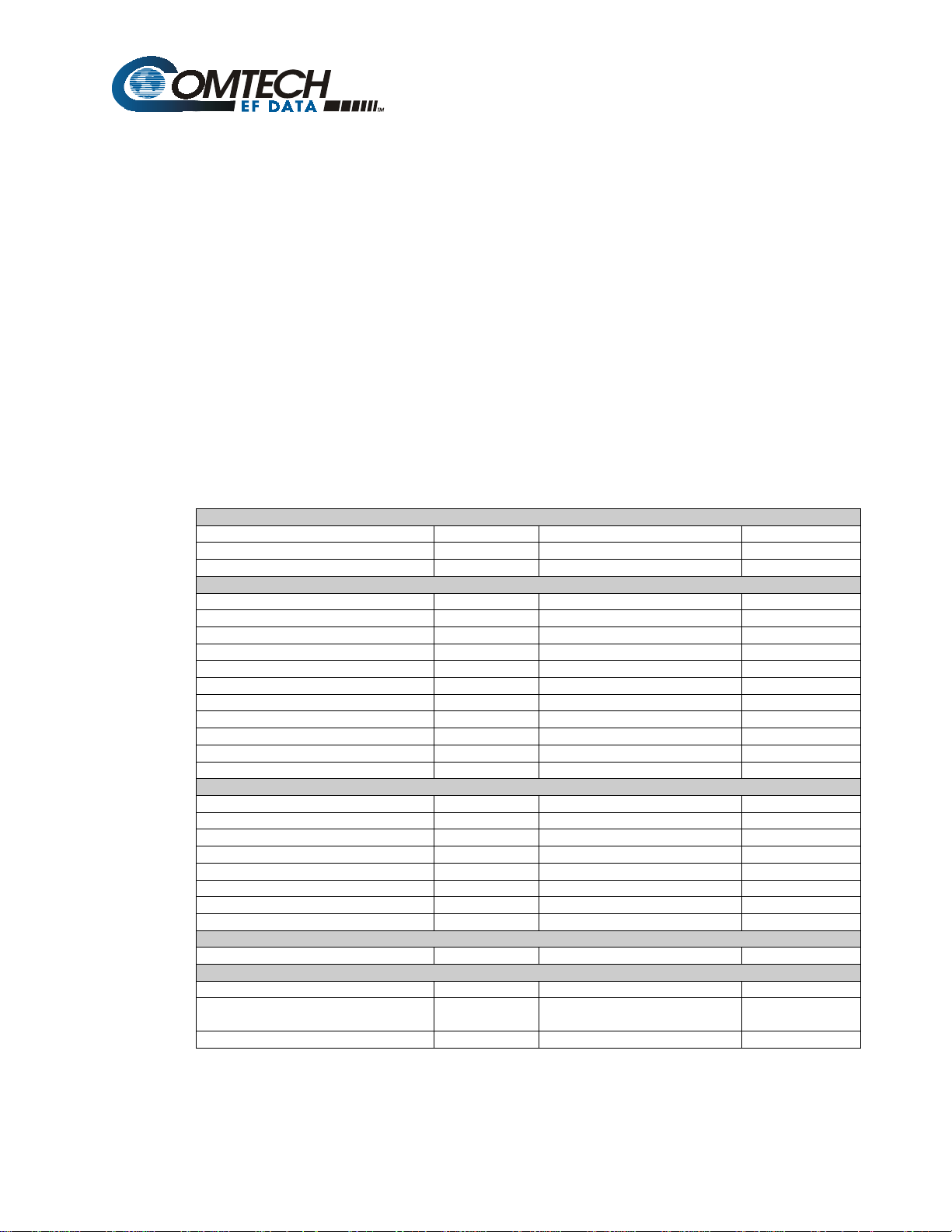
Table 3-4. Initial Defaults
Configuration Backup #n (n = 1 or 2)
Off
Off
Configuration Independent Prime #n (n = 1 through 8)
Off
Low
Low
None
Off
Low
Low
Configuration Dependent Prime #n (n = 1 through 8)
Off
Off
Low
Low
None
None
Configuration Operation Mode
Manual
Utility System
Backup #1 Multiplexer
Backup #2 Mulitiplexer No
Prime Demod #6, 7 Delay
Prime Demod #8 Delay
Prime #1, 2, 3, 4 Multiplexer
External Clock #1, 2, 3, 4 Unbalanced
Insert Data Input #1, 2, 3, 4 Normal
D&I #5, 6, 7, 8
External Clock #5, 6, 7, 8
Prime #1, 2, 3, 4 Multiplexer
Prime #5, 6, 7, 8 Multiplexer No
D&I #1, 2, 3, 4 Unbalanced
External Clock #1, 2, 3, 4 Unbalanced
External Clock #5, 6, 7, 8
Insert Data Input #5, 6, 7, 8
No
None
None
No
Unbalanced
Unbalanced
Normal
No
Unbalanced
Unbalanced
Normal
Wire)
Filename: T_ERRATA
1
Page 6

Page 7

Errata C
Comtech EFData Documentation Update
Subject:
Date:
Document:
Part Number:
Collating Instructions:
Related Documents
The following documents are referenced in this manual:
• Department of Defense (DOD) MIL-STD-188-114A, “Electrical Characteristics of Digital
Interface Circuits”
• M-2000 Multiplexer Installation and Operation Manual
• Comtech EF Data CRS-280L 1:N Redundancy Switch Installation and Operation Manual
Changes to Related Documents
October 13, 2003
SMS-7000 Modem protection Switch Installation and Operation
Manual, Rev. 3, dated September 30, 1999
MN/SMS7000.EC3
Attach this page to page viii
Filename: T_ERRATA 1
Page 8

Page 9

Comtech EFData is an ISO 9001
Registered Company.
SMS-7000
Modem Protection Switch
Installation and Operation Manual
Part Number MN/SMS7000.IOM
Revision 3
September 30, 1999
Copyright © Comtech EFData, 2000. All rights reserved. Printed in the USA.
Comtech EFData, 2114 West 7th Street, Tempe, Arizona 85281 USA, (480) 333-2200, FAX: (480) 333-2161.
Page 10

Customer Support
Contact the Comtech EFData Customer Support Department for:
• Product support or training
• Information on upgrading or returning a product
• Reporting comments or suggestions concerning manuals
A Customer Support representative may be reached at:
Comtech EFData
Attention: Customer Support Department
2114 West 7th Street
Tempe, Arizona 85281 USA
(480) 333-2200 (Main Comtech EFData Number)
(480) 333-4357 (Customer Support Desk)
(480) 333-2161 FAX
or, E-Mail can be sent to the Customer Support Department at:
service@comtechefdata.com
Contact us via the web at www.comtechefdata.com
1. To return a Comtech EFData product (in-warranty and out-of-warranty) for
repair or replacement:
2. Request a Return Material Authorization (RMA) number from the Comtech
EFData Customer Support Department.
3. Be prepared to supply the Customer Support representative with the model
number, serial number, and a description of the problem.
4. To ensure that the product is not damaged during shipping, pack the product in
its original shipping carton/packaging.
5. Ship the product back to Comtech EFData. (Shipping charges should be prepaid.)
For more information regarding the warranty policies, see Warranty Policy, p. xii.
.
ii Rev. 3
Page 11

Table of Contents
Customer Support ...................................................................................................................................................... ii
Overview of Changes to Previous Edition ............................................................................................................. viii
Overview of Changes to Previous Edition ............................................................................................................. viii
About this Manual................................................................................................................................................... viii
EMC Compliance ........................................................................................................................................................x
Warranty Policy........................................................................................................................................................ xii
CHAPTER 1. INTRODUCTION.......................................................................................................... 1–1
1.1
Overview......................................................................................................................................................1–2
1.1.1 Compatibility ...........................................................................................................................................1–2
1.1.2 Data Formats............................................................................................................................................1–4
1.1.3 Options.....................................................................................................................................................1–5
1.1.4 Protection Switch.....................................................................................................................................1–6
1.2 Description ..................................................................................................................................................1–6
1.2.1 Switch Controller Unit (SCU)..................................................................................................................1–8
1.2.2 Data Switch Unit (DSU) ..........................................................................................................................1–9
1.2.3 IF Switch Unit (IFU)..............................................................................................................................1–11
1.3 Specifications ............................................................................................................................................1–12
CHAPTER 2. INSTALLATION ...........................................................................................................2–1
2.1
Unpacking ...................................................................................................................................................2–1
2.2 Equipment Inspection ................................................................................................................................2–2
2.2.1 Included Parts...........................................................................................................................................2–2
2.2.2 Back Mount (Hinged) Hardware Kit........................................................................................................2–3
2.2.3 Top Mount Hardware Kit.........................................................................................................................2–4
2.2.4 Cables.......................................................................................................................................................2–5
2.2.5 Tools Required.........................................................................................................................................2–6
Rev. 3 iii
Page 12

Preface SMS-7000 Modem Protection Switch
2.3 Mounting .....................................................................................................................................................2–7
2.3.1 Description...............................................................................................................................................2–7
2.3.1.1 Top Mount.......................................................................................................................................2–7
2.3.1.2 Back Mount .....................................................................................................................................2–7
2.3.2 Installation................................................................................................................................................2–8
2.3.2.1 Switch Control Unit.........................................................................................................................2–8
2.3.2.2 Top Mount Installation....................................................................................................................2–8
2.3.2.3 Back Mount Installation ................................................................................................................2–10
2.4 Cable Installation......................................................................................................................................2–13
2.4.1 Interconnecting the Switch Components................................................................................................2–13
2.4.1.1 SCU (J4) to DSU (J11) Interface...................................................................................................2–15
2.4.1.2 Remote Connection .......................................................................................................................2–15
2.4.1.3 DSU (J12) to IFU (J1)...................................................................................................................2–16
2.4.1.4 DSU J9 (BU1) Modem Connector to Backup Modem..................................................................2–16
2.4.1.5 DSU JI CH to Prime Modem.........................................................................................................2–16
2.4.1.6 IFU Connections (CP17 through CP36)........................................................................................2–17
2.5 Configuration Setup .................................................................................................................................2–17
2.5.1 Configure Rack Setup............................................................................................................................2–17
2.5.2 Trouble Shoot Configuration .................................................................................................................2–19
2.6 DSU Data Connections (J1 through J10)................................................................................................2–20
2.6.1 SCU Rear Panel .....................................................................................................................................2–22
2.6.1.1 User Remote (J1)...........................................................................................................................2–22
2.6.1.2 Modem Remote (J2)......................................................................................................................2–23
2.6.1.3 Switch Faults (J3)..........................................................................................................................2–23
2.6.1.4 Prime Mod (Online) Status (J6) ....................................................................................................2–24
2.6.1.5 Prime Mod (Online) Status (J5) ....................................................................................................2–25
2.6.2 DSU Terrestrial Data Interfaces.............................................................................................................2–26
2.6.2.1 EIA-422/8 kbit/s Terrestrial Data (J6)...........................................................................................2–27
2.6.2.2 V.35/EIA-232-C Terrestrial Data (J1)...........................................................................................2–29
2.6.2.3 Engineering Service Channel Data (J4).........................................................................................2–30
2.6.2.4 Alarms (J2)....................................................................................................................................2–31
2.6.2.5 ADPCM Audio Data (J5)..............................................................................................................2–32
2.6.2.6 Balanced G.703/Drop & Insert Data (J3) ......................................................................................2–33
2.6.2.7 Unbalanced Data Ports ..................................................................................................................2–34
2.6.3 IFU Uplink and Downlink IF (CP1 through CP16) ...............................................................................2–35
CHAPTER 3. OPERATION ................................................................................................................3–1
3.1
Configuration..............................................................................................................................................3–1
3.1.1 Backup Modems ......................................................................................................................................3–2
3.1.2 Prime Modems .........................................................................................................................................3–2
3.2 Front Panel..................................................................................................................................................3–2
3.2.1 LED Indicators.........................................................................................................................................3–3
3.2.2 Front Panel Controls ................................................................................................................................3–4
3.3 Menu System...............................................................................................................................................3–5
3.4 Front Panel Menu.......................................................................................................................................3–7
3.4.1 Configuration Backup 1 and 2 Menu.......................................................................................................3–9
3.4.2 Configuration Independent Prime 1 through 8 Menu.............................................................................3–11
iv Rev. 3
Page 13

SMS-7000 Modem Protection Switch Preface
3.4.3 Configuration Dependent Prime 1 through 8 Menu...............................................................................3–15
3.4.4 Configuration Load/Verify Menu ..........................................................................................................3–17
3.4.5 Configuration Operation Mode Menu....................................................................................................3–19
3.4.6 System Status Switching Menu..............................................................................................................3–21
3.4.7 System Status Configuration Menu........................................................................................................3–23
3.4.8 Faults/Alarms Menu...............................................................................................................................3–25
3.4.9 Stored Faults/Alarms Menu ...................................................................................................................3–27
3.4.10 Utility System Menu..........................................................................................................................3–29
3.5 Setup and Configuration..........................................................................................................................3–30
3.5.1 Utility Setup...........................................................................................................................................3–30
3.5.2 Configuration .........................................................................................................................................3–30
3.5.2.1 Backup...........................................................................................................................................3–30
3.5.2.2 Prime .............................................................................................................................................3–31
3.5.2.3 Load/Verify ...................................................................................................................................3–31
3.5.2.4 Operation Mode.............................................................................................................................3–32
3.6 Faults .........................................................................................................................................................3–32
3.7 Revision Status..........................................................................................................................................3–32
3.8 Initial Defaults ..........................................................................................................................................3–33
CHAPTER 4. THEORY OF OPERATION.......................................................................................... 4–1
4.1
Interfaces.....................................................................................................................................................4–1
4.1.1 Configuration ...........................................................................................................................................4–1
4.1.2 Terrestrial Data ........................................................................................................................................4–3
4.1.3 IF Uplink/Downlink.................................................................................................................................4–3
4.1.4 Monitors...................................................................................................................................................4–4
4.1.5 Modem Interfaces.....................................................................................................................................4–5
4.2 Switching Modes.........................................................................................................................................4–6
4.2.1 Manual Mode...........................................................................................................................................4–6
4.2.2 Auto Mode ...............................................................................................................................................4–6
CHAPTER 5. MAINTENANCE...........................................................................................................5–1
5.1
Periodic Maintenance.................................................................................................................................5–1
5.2 Software Revisions......................................................................................................................................5–1
5.3 Fault Action.................................................................................................................................................5–2
5.3.1 Modem.....................................................................................................................................................5–2
5.3.2 Switch ......................................................................................................................................................5–3
APPENDIX A. REMOTE CONTROL OPERATION............................................................................. A–1
A.1
General .......................................................................................................................................................A–1
A.2 Message Structure .....................................................................................................................................A–3
A.2.1 Start Characters...................................................................................................................................A–4
Rev. 3 v
Page 14

Preface SMS-7000 Modem Protection Switch
A.2.2 Command/Response ...........................................................................................................................A–4
A.2.3 End Character .....................................................................................................................................A–5
A.3 Configuration Commands/Responses......................................................................................................A–6
A.3.1 Backup Modem...................................................................................................................................A–6
A.3.2 Prime Modem .....................................................................................................................................A–7
A.3.3 Switch ................................................................................................................................................. A–8
A.3.4 Breakout..............................................................................................................................................A–9
A.3.5 System ................................................................................................................................................A–9
A.3.6 Mode.................................................................................................................................................A–10
A.4 Status Commands/Responses .................................................................................................................A–11
A.5 Stored Faults ............................................................................................................................................A–20
A.6 About Switch............................................................................................................................................A–21
APPENDIX B. M-2000 MULTIPLEXER UTILIZATION ...................................................................... B–1
B.1
Installation .................................................................................................................................................B–1
B.2 Operation ...................................................................................................................................................B–3
Figures
Figure 1-1. SMS-7000 ..............................................................................................................................................1–1
Figure 1-2. Block diagram........................................................................................................................................1–7
Figure 1-3. SCU front panel .....................................................................................................................................1–8
Figure 1-4. SCU rear panel.......................................................................................................................................1–8
Figure 1-5. DSU/IFU terrestrial side ........................................................................................................................1–9
Figure 1-6. DSU/IFU modem side..........................................................................................................................1–10
Figure 2-1. Top mount installation...........................................................................................................................2–9
Figure 2-2. Back mount (hinge) installation...........................................................................................................2–11
Figure 2-3. Hinge mount, side view .......................................................................................................................2–12
Figure 2-4. Hinge mount, top view.........................................................................................................................2–12
Figure 2-5. Typical switch installation ...................................................................................................................2–14
Figure 2-6. SCU rear panel.....................................................................................................................................2–22
Figure 2-7. DSU/IFU terrestrial side ......................................................................................................................2–26
Figure 3-1. SMS-7000 front panel view...................................................................................................................3–1
Figure 3-2. Main menu.............................................................................................................................................3–7
Figure 3-3. Configuration backup 1 and 2 menu ......................................................................................................3–8
Figure 3-4. Configuration independent prime 1 through 8 menu ...........................................................................3–10
Figure 3-5. Configuration dependent prime 1 through 8 menu ..............................................................................3–14
Figure 3-6. Configuration load/verify menu...........................................................................................................3–16
Figure 3-7. Configuration operation mode menu ...................................................................................................3–18
Figure 3-8. System status switching menu .............................................................................................................3–20
Figure 3-9. System status configuration menu .......................................................................................................3–22
Figure 3-10. Faults/alarms menu ............................................................................................................................3–24
Figure 3-11. Stored faults/alarms menu..................................................................................................................3–26
Figure 3-12. Utility system menu ...........................................................................................................................3–28
Figure 4-1. IF switch block diagram.........................................................................................................................4–2
Figure B-1. Terrestrial data interconnections ...........................................................................................................b–2
vi Rev. 3
Page 15

SMS-7000 Modem Protection Switch Preface
Tables
Table 1-1. SMS-7000 modem hardware compatibility.............................................................................................1–3
Table 1-2. Data formats ............................................................................................................................................1–4
Table 1-3. Options ....................................................................................................................................................1–5
Table 1-4. Protection switch.....................................................................................................................................1–6
Table 1-5. SMS-7000 specifications.......................................................................................................................1–12
Table 2-1. 50-pin cable...........................................................................................................................................2–16
Table 2-2. Trouble shooting ...................................................................................................................................2–19
Table 2-3. DSU data connections (J1 through J10) ................................................................................................2–20
Table 2-4. User remote EIA-485/EIA-232 connector (J1) .....................................................................................2–22
Table 2-5. Modem remote EIA-485 connector (J2)................................................................................................2–23
Table 2-6. Switch faults connector (J3)..................................................................................................................2–23
Table 2-7. Prime mod online connector (J6) ..........................................................................................................2–24
Table 2-8. Prime demod online connector (J5).......................................................................................................2–25
Table 2-9. EIA-422 terrestrial data connectors (J6)................................................................................................2–27
Table 2-10. V.35/EIA-232 terrestrial data connectors (J1).....................................................................................2–29
Table 2-11. Engineering service channel data connectors (J4)...............................................................................2–30
Table 2-12. Alarms (J2) connectors........................................................................................................................2–31
Table 2-13. ADPCM audio data (J5) connectors....................................................................................................2–32
Table 2-14. Balanced G.703/drop & insert data connectors (J3)............................................................................2–33
Table 2-15. Unbalanced data connectors................................................................................................................2–34
Table 2-16. IFU uplink/IF downlink data connectors.............................................................................................2–35
Table 3-1. LED indicators ........................................................................................................................................3–3
Table 3-2. Front panel keypad..................................................................................................................................3–4
Table 3-3. Revision status.......................................................................................................................................3–32
Table 3-4. Initial defaults........................................................................................................................................3–33
Table 4-1. DSM interfaces........................................................................................................................................4–3
Table 4-2. SCU chassis connectors...........................................................................................................................4–4
Table 4-3. SCU rear panel connectors......................................................................................................................4–5
Table 5-1. Switch fault analysis................................................................................................................................5–3
Table A-1. SMS-7000 remote control: SMS-658/SMS-758 comparison table ........................................................a–2
Table B-1. SMS-7000/M-2000 50-pin to 37-pin interface cable pinouts .................................................................b–3
Rev. 3 vii
Page 16

Preface SMS-7000 Modem Protection Switch
Overview of Changes to Previous Edition
This revision supersedes part number MN/SMS7000 Rev. 2 dated October 3, 1997.
A summary of the changes made for Rev. 2 includes:
Chapter 1 Updated Compatibility and Data Formats paragraph and specified that
the SDM-300 modem must be the 50-pin configuration.
Added Options paragraph.
Revised Figure 1-2 to include cable part numbers.
Updated specifications paragraph to the current specification.
Relocated mounting information to Chapter 2.
Chapter 2 Added Equipment Inspection paragraphs to reflect mounting kits and
required tooling.
Added cable information.
Revised mounting instructions by including description and installation
information.
Added trouble shooting information for installation procedures.
Chapter 3 Updated software menu from version 2.1.7 to 2.1.8.
Added revision emulation and initial default paragraphs.
Appendix A Updated to software version 2.1.8.
General Deleted Mounting appendix.
Reidentified Multiplexer section as Appendix B.
About this Manual
This manual provides installation and operation information for the Comtech EFData
SMS-7000 Modem Protection Switch. This is a technical document intended for earth
station engineers, technicians, and operators responsible for the operation and
maintenance of the SMS-7000.
Related Documents
The following documents are referenced in this manual:
• Department of Defense (DOD) MIL-STD-188-114A, “Electrical Characteristics
of Digital Interface Circuits”
• M-2000 Multiplexer Installation and Operation Manual
viii Rev. 3
Page 17
SMS-7000 Modem Protection Switch Preface
Conventions and References
Cautions and Warnings
CAUTION indicates a hazardous situation that, if not avoided, may result in
minor or moderate injury. CAUTION may also be used to indicate other
CAUTION
unsafe practices or risks of property damage.
WARNING indicates a potentially hazardous situation that, if not avoided,
could result in death or serious injury.
WARN ING
Metric Conversion
Metric conversion information is located on the inside back cover of this manual. This
information is provided to assist the operator in cross-referencing English to Metric
conversions.
Recommended Standard Designations
Recommended Standard (RS) Designations have been superseded by the new designation
of the Electronic Industries Association (EIA). References to the old designations are
shown only when depicting actual text displayed on the screen of the unit (RS-232, RS485, etc.). All other references in the manual will be shown with the EIA designations
(EIA-232, EIA-485, etc.) only.
Military Standards
References to “MIL-STD-188” apply to the 114A series (i.e., MIL-STD-188-114A),
which provides electrical and functional characteristics of the unbalanced and balanced
voltage digital interface circuits applicable to both long haul and tactical
communications. Specifically, these references apply to the MIL-STD-188-114A
electrical characteristics for a balanced voltage digital interface circuit, Type 1 generator,
for the full range of data rates. For more information, refer to the Department of Defense
(DOD) MIL-STD-188-114A, “Electrical Characteristics of Digital Interface Circuits.”
Trademarks
Other product names mentioned in this manual may be trademarks or registered
trademarks of their respective companies and are hereby acknowledged.
Rev. 3 ix
Page 18

Preface SMS-7000 Modem Protection Switch
Reporting Comments or Suggestions Concerning this Manual
Comments and suggestions regarding the content and design of this manual will be
appreciated. To submit comments, please contact the Comtech EFData Customer Support
Department.
EMC Compliance
EN55022 Compliance
This equipment meets EN55022.
This is a Class A product. In a domestic environment it may cause radio interference in
which the user may be required to take adequate measures.
Federal Communications Commission (FCC)
Note: All cables shall be shielded.
This equipment has been tested and found to comply with the limits for a Class A digital
device, pursuant to Part 15 of the FCC rules. These limits are designed to provide
reasonable protection against harmful interference when the equipment is operated in a
commercial environment.
This equipment generates, uses, and can radiate radio frequency energy and, if not
installed and used in accordance with the instruction manual, may cause harmful
interference to radio communications. Operation of this equipment in a residential area is
likely to cause harmful interference in which case the user will be required to correct the
interference at his own expense.
x Rev. 3
Page 19
SMS-7000 Modem Protection Switch Preface
Low Voltage Directive (LVD)
The following information is applicable for the European Low Voltage Directive
(EN60950):
<HAR>
Type of power cord required for use in the European Community.
CAUTION: Double-pole/Neutral Fusing.
!
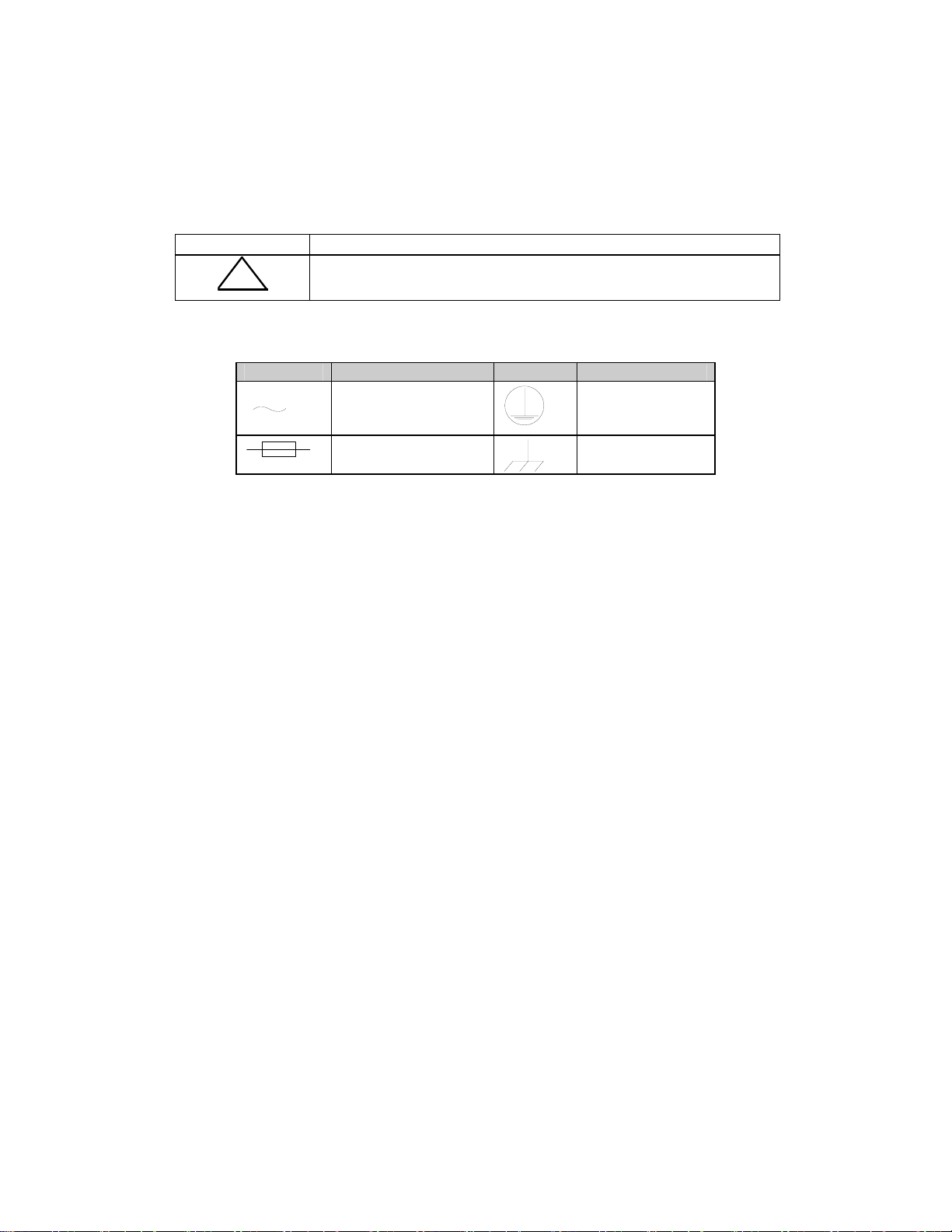
International Symbols:
Symbol Definition Symbol Definition
ACHTUNG: Zweipolige bzw. Neutralleiter-Sicherung.
Alternating Current.
Protective Earth
Fuse.
Chassis Ground.
Notes:
1. For additional symbols, refer to “Cautions” listed earlier in this preface.
2. Applicable testing is routinely performed as a condition of manufacturing on all
units to ensure compliance with requirements of EN60950 for Safety.
Rev. 3 xi
Page 20

Preface SMS-7000 Modem Protection Switch
Warranty Policy
This Comtech EFData product is warranted against defects in material and workmanship
for a period of one year from the date of shipment. During the warranty period, Comtech
EFData will, at its option, repair or replace products that prove to be defective.
For equipment under warranty, the customer is responsible for freight to Comtech
EFData and all related custom, taxes, tariffs, insurance, etc. Comtech EFData is
responsible for the freight charges only for return of the equipment from the factory to
the customer. Comtech EFData will return the equipment by the same method (i.e., Air,
Express, Surface) as the equipment was sent to Comtech EFData.
Limitations of Warranty
The foregoing warranty shall not apply to defects resulting from improper installation or
maintenance, abuse, unauthorized modification, or operation outside of environmental
specifications for the product, or, for damages that occur due to improper repackaging of
equipment for return to Comtech EFData.
No other warranty is expressed or implied. Comtech EFData specifically disclaims the
implied warranties of merchantability and fitness for particular purpose.
Exclusive Remedies
The remedies provided herein are the buyer's sole and exclusive remedies. Comtech
EFData shall not be liable for any direct, indirect, special, incidental, or consequential
damages, whether based on contract, tort, or any other legal theory.
Disclaimer
Comtech EFData has reviewed this manual thoroughly in order that it will be an easy-touse guide to your equipment. All statements, technical information, and
recommendations in this manual and in any guides or related documents are believed
reliable, but the accuracy and completeness thereof are not guaranteed or warranted, and
they are not intended to be, nor should they be understood to be, representations or
warranties concerning the products described. Further, Comtech EFData reserves the
right to make changes in the specifications of the products described in this manual at any
time without notice and without obligation to notify any person of such changes.
If you have any questions regarding your equipment or the information in this manual,
please contact the Comtech EFData Customer Support Department.
xii Rev. 3
Page 21
Chapter 1.
INTRODUCTION
1
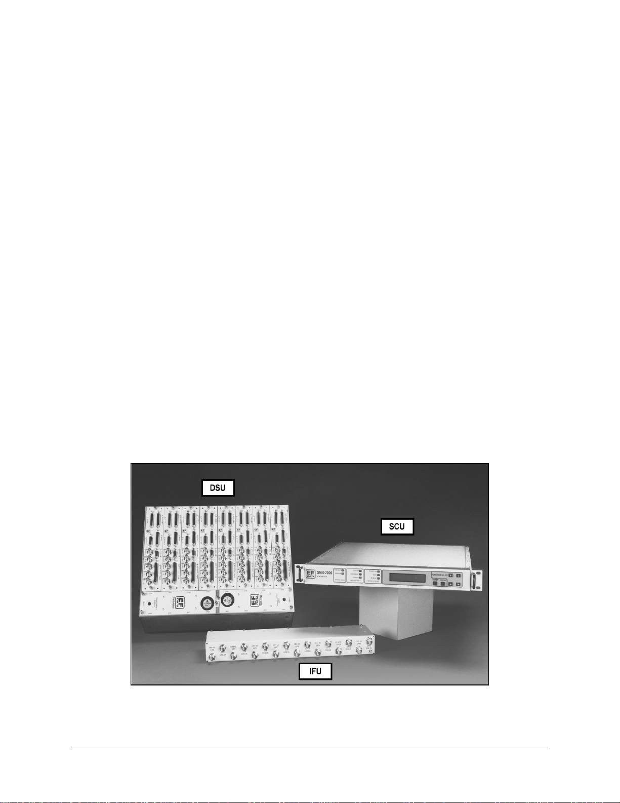
This chapter provides an overview, description, and specifications for the SMS-7000
satellite modem protection switch. The SMS-7000 is hereinafter referred to in this
manual as “the switch”, and includes the following components (refer to Figure 1-1):
•
IFU Intermediate Frequency Switch Unit
•
DSU Data Switch Unit
•
SCU Switch Control Unit
Figure 1-1. SMS-7000
Rev. 3 1–1
Page 22

Introduction SMS-7000 Modem Protection Switch
1.1 Overview
The switch is specifically designed to perform automatic redundancy switching for any
combination of up to two backup and eight prime Comtech EFData satellite modems. Up
to eight separate uplinks and downlinks can be accessed by the user at any time.
Each switch channel has a built-in breakout panel that is automatically configured to
support overhead, non-overhead, and programmable data-type modems. Configuration
and control of the switch and attached modems may be performed from a terminal or PC
connected to the switch remote port (refer to Appendix A); or directly from the switch
front panel (refer to Chapter 3).
The switch is compatible with the M-2000 multiplexer (refer to Appendix C for more
information).
The switch is tested and certified to CE-Mark requirements.
1.1.1 Compatibility
The switch is designed to operate with the following Comtech EFData modems:
•
SDM-100 • SDM-300A (see Note)
•
SDM-308-4 • SDM-6000
•
SDM-308-5 • SDM-8000
•
SDM-309B • SLM-3650 (see Note)
•
SDM-650B • SLM-6650
•
SDM-300 (see Note) • SLM-8650
Note:
Use the 50-pin D connector configuration with the switch.
1–2 Rev. 3
Page 23

SMS-7000 Modem Protection Switch Introduction
For modem compatibility, refer to Table 1-1.
Table 1-1. SMS-7000 Modem Hardware Compatibility
Rack Setup Backup Comments
SDM-308-4
SDM-6000
SDM-308-5
SDM-6000
SDM-309B
SDM-6000
SDM-308-4
SDM-8000
SDM-308-5
SDM-8000
SDM-309B
SDM-8000
SDM-650B
SDM-100A
SDM-100A
SDM-300/-300A
SDM-308-4
SDM-300/-300A
SDM-308-5
SDM-300/-300A
SDM-309
SDM-300/-300A
SDM-650B
SDM-300/-300A
SDM-6000
SDM-300/-300A
SLM-3650 None Only compatible with SLM-3650, incorporating the 50-pin Data
SLM-6650 None Only compatible with SLM-6650.
SLM-8650 None Only compatible with SLM-8650.
Either SDM-6000 must be configured as Modem Type 1 to be compatible
with SDM-308-4 (M1200P).
Note:
SDM-6000 must be configured as Modem Type 4 to be
compatible with SDM-308-4 (old IDR interface). (See Note 1)
Either SDM-6000 must be configured as Modem Type 3 to be compatible
with SDM-308-5. (See Note 1)
Either SDM-6000 must be configured as Modem Type 2 to be compatible
with SDM-309 (M1200P). (See Note 1)
Either SDM-8000 must be configured as Modem Type 1 to be compatible
with SDM-308-4.(M1200P).
Note:
SDM-8000 must be configured as Modem Type 4 to be
compatible with SDM-308-4 (old IDR interface) or Type 5 to be
compatible with SDM-308-4 (M1200/RS). (See Note 1)
Either SDM-8000 must be configured as Modem Type 3 to be compatible
with SDM-308-5. (See Note 1)
Either SDM-8000 must be configured as Modem Type 2 to be compatible
with SDM-309 (M1200P). (See Note 1)
Either SDM-100A must have sequential decoder option, and be configured
as Modem Type 1 to be compatible with SDM-650B. (See Note 1)
Either SDM-300/300A, incorporating the 50-pin Data Interface connector
must be configured to emulate an SDM-100A (Ver: 15.7.1).
Either SDM-300/300A, incorporating the 50-pin Data Interface connector
must be configured to emulate an SDM-308-4 (Ver: 4.03, 6.05, or
7.03).
Either SDM-300/300A, incorporating the 50-pin Data Interface connector
must be configured to emulate an SDM-308-5 (Ver: 6.08).
Either SDM-300/300A, incorporating the 50-pin Data Interface connector
must be configured to emulate an SDM-309 (Ver: 6.04).
Either SDM-300/300A, incorporating the 50-pin Data Interface connector
must be configured to emulate an SDM-650B (Ver; 4.12A or 4.16)
Either SDM-300/300A, incorporating the 50-pin Data Interface connector
must be configured to emulate an SDM-6000 (Ver: 5.1.1)
Interface connector.
Notes
:
1. Modem control feature supported by latest code release for SDM-100, SDM-6000, and
SDM-8000.
2. Backup modems are always compatible with primes of like models when they are
comparably equipped.
3. Consult Comtech EFData Customer Support for combinations not shown in Table 1-1.
4. Compatibility differences between modems exist due to the fact that the specific
capabilities of modems vary. For example, the SDM-8000 has a larger set of framing
structure parameters than the SDM-300, etc.
Rev. 3 1–3
Page 24

Introduction SMS-7000 Modem Protection Switch
1.1.2 Data Formats
Table 1-2 lists the data formats that the switch will support.
Table 1-2. Data Formats
Data Type Connector
V.35 Data 25-pin D
EIA-422/MIL-STD-188 Data IDR 8K Data Channel 37-pin D
G.703 Balanced 15-pin D
G.703 Unbalanced Coax BNC
EIA-232 Data 25-pin D
ADPCM Audio Data or 64K Data Overhead 9-pin D
Engineering Data Channel ASYNC Overhead 25-pin D
Alarms 25-pin D
Under the following conditions, the switch is designed to operate with prime modems
configured with different overhead data types, such as, IDR, IBS, D&I, ASYNC, or
NONE; and/or with different terrestrial data types, such as, EIA-422, V.35, or G.703:
•
Modems must be one of the following models:
!
SDM-6000
!
SDM-8000
!
SLM-6650
!
SLM-8650
•
Backup modems must have an AS/2876 interface relay board option installed, in
order for the backup modem to switch between IDR, IBS, and Custom mode.
•
Backup modems’ switching mode must be dependent when there is a mixture of
prime modem types. Example: Prime 1 is IDR, and Prime 2 is IBS, EIA-422.
Backup modems must be comparably equipped to the prime modems assigned.
(Example: Backup #1 is an SDM-8000 configured with a relay card and a sequential
decoder. It can backup prime modems (SDM-8000) that are configured as prime #1 IDR
and prime #2 configured for Custom sequential. Backup # 2 can also be an SDM-300
backing up a set of prime SDM-300 modems. The backup modems can be directed to a
specific set of modems.)
1–4 Rev. 3
Page 25
SMS-7000 Modem Protection Switch Introduction
1.1.3 Options
Table 1-3 lists the options that are applicable to the switch.
Table 1-3. Options
Input Power Mounting Kit IF Switch Switch Type Switch Quantity Option
AC Top KT/5275 No IF Switch Universal 1 None
DC Back KT/5274
75Ω Attached
50Ω Attached
75Ω Unattached
50Ω Unattached
2
3
4
5
6
7
8
Rev. 3 1–5
Page 26

Introduction SMS-7000 Modem Protection Switch
1.1.4 Protection Switch
Refer to Table 1-4 for part numbers of various switch component.
Table 1-4. Protection Switch
Part Number Description
PL/4800 Chassis Controller
PL/4801-1
PL/4801-2
PL/4802 Switch, Data
PL/4803 Power Supply, AC
PL/4831 Power Supply, DC
CA/5343 Cable Assembly, 15-Pin, EMI
CA/5361-1 Cable Assembly, Switch to Controller, 6 ft. (182.88 cm)
1.2 Description
The switch (Figure 1-1) is composed of three units:
Switch Control Unit (SCU)
•
and configuration.
Data Switch Unit (DSU)
•
data configuration and backup modem data switching.
IF Switch (IFU)
•
switching.
IF Switch, 75
IF Switch, 50
Ω
Ω
— User interface for switch and modem control
— As commanded by the SCU, performs terrestrial
— As commanded by the SCU, performs backup modem IF
This 3-chassis arrangement gives the user control of the switch from the one unit (1U)
rack mounted SCU front panel. The DSU and IFU, which contain all terrestrial and link
interfaces, are mounted inside the rack to minimize rack and external interface cabling.
These units will accommodate the particulars of external interface requirements. They
can be separated or joined together and mounted either in the rear or on the top of the
rack.
1–6 Rev. 3
Page 27
SMS-7000 Modem Protection Switch Introduction
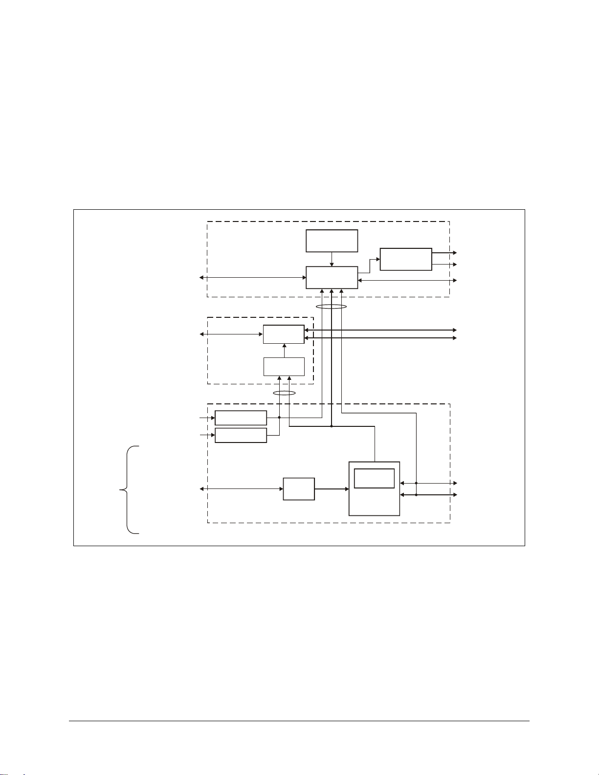
The switch functional block diagram (Figure 1-2) displays the functional partitioning and
interconnection between the three chassis.
Two cables interconnect the three units. The SCU and DSU are connected via a cable
that transfers power, faults, and switch control between the two chassis. Power, modem
faults, and switch faults originate from the DSU, while switch control commands are
initiated by the SCU. The IFU is connected to the DSU in the same manner.
CONTROL UNIT
REMOTE CONTROL
EIA-485/232
UP/DOWN LINK
16 COAX
IF SWITC H U NIT
COAX
SWITCH
SLAVE
CONTROLLER
FRONT PANEL
CONTROLLER
CA/5361
FAULT AND
STATUS RELAYS
DB9
SWITCH FAULTS
x2 DB2 5
ONLINE STATUS
DB9 EIA-485
MODEM REMOTE
16 COAX
PRIMARY MODEM IF
RX/TX
4 COAX
BACKUP MODEM IF
RX/TX
TERRESTRIAL
DATA, x8
PRIME POWER IN
PRIME POWER IN
BALANCED DATA
DB25
EIA-422
DB15
G.703
V.3 5
DB25
EIA-232-C
DB25
UNBALANCED DATA 5 COAX
D&I
G.703
EXTERNAL CLOCK
AUXILIARY DATA
ADPCM
DB9
ESC
DB25
ALARMS
DB25
CA/0755
LOW VOLTAGE
POWER
LOW VO LTAGE
POWER
BOP
x8
DATA SWITCH UNIT
Figure 1-2. Block Diagram
IBS/IDR
EIA-485
FAULTS
SLAVE
CONTROLLER
DATA SWITCH
M:N x8
x8 DB5 0
PRIMARY MODEM DATA
RX/TX
x2 DB5 0
BACKUP MODEM DATA
RX/TX
Rev. 3 1–7
Page 28
Introduction SMS-7000 Modem Protection Switch
1.2.1 Switch Controller Unit (SCU)
The SCU is a one unit (1U), 19-inch (48.26 cm) rack-mounted chassis that provides the
configuration and automatic switching control functions. Rear panel connectors on this
chassis provide all user remote control and status interfaces and rack internal control
interfaces. The front panel provides local control of the switch.
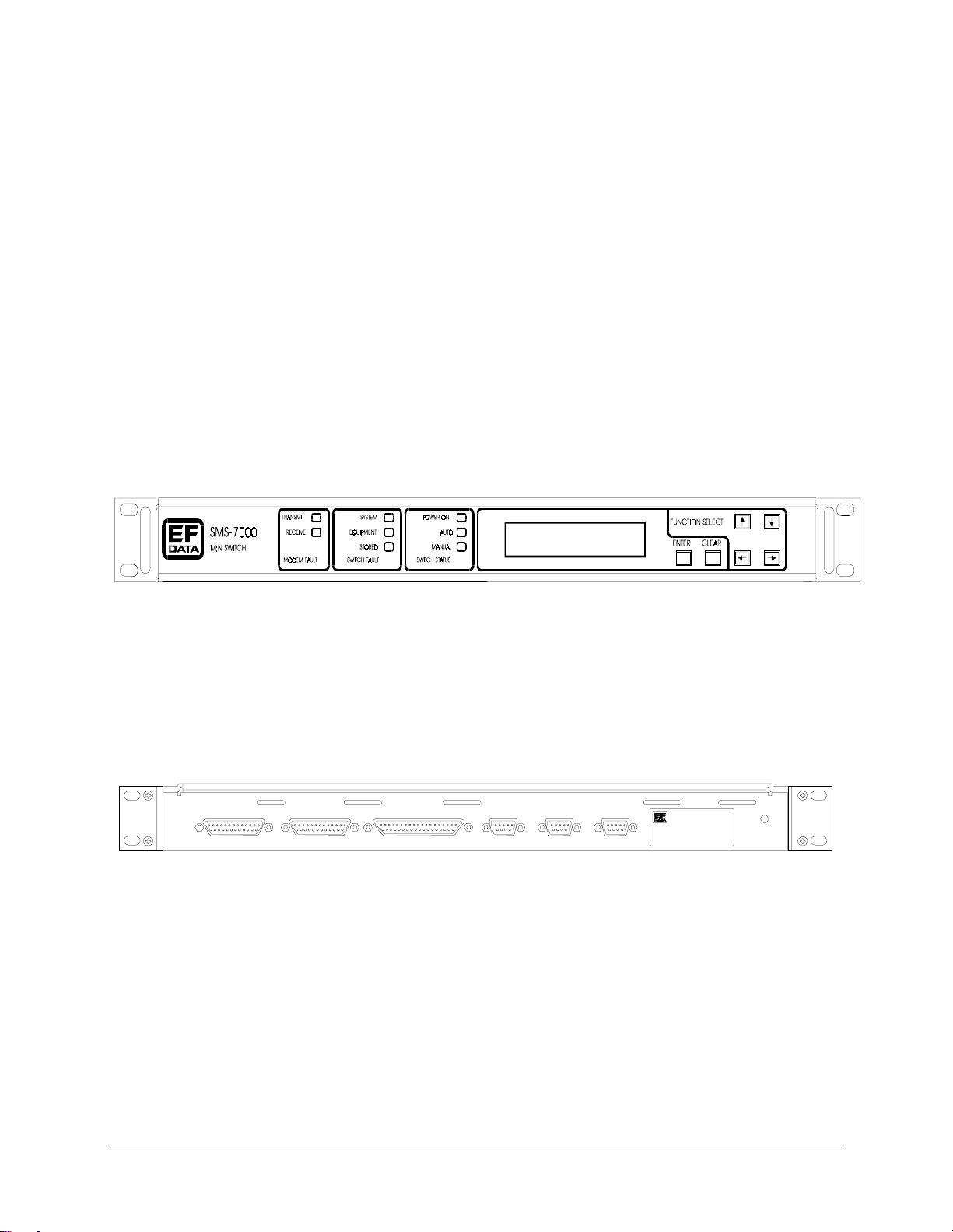
The SCU front panel (Figure 1-3) provides the user with visual fault and status
indicators. The back-lit display and keypad provide the local user control interface. The
front panel is a typical Comtech EFData modem front panel status and control interface.
The switch front panel supports all functions of the remote port. The user may configure
both the switch and associated modems as well as query status and faults.
Note:
The modem control feature is only available with certain modems. Refer to the
compatibility chart (Table 1-3) for specific applications.
Figure 1-3. SCU Front Panel
The SCU rear panel (Figure 1-4) accommodates the user serial command interface for
remote configuration and status. These interfaces are also shown in the block diagram
(Figure 1-2).
PRIME MOD
J6 J6
STATUS
PRIME MOD
STATUS
DATA SWITCH
INTER FACE
J4
J3
SWITCH
FAULTS
MODEM
J2 J1
REMOTE
USER
REMOTE
Figure 1-4. SCU Rear Panel
Prime modulator and demodulator status and switch faults are provided on dedicated I/O
connectors. Status and fault conditions are indicated at these connectors by opening and
closing relay contacts, which may be used to directly trigger external alarms and
indicators. The modem remote port is the control interface to all modems attached to the
switch. The Data Switch Interface, which carries control and fault information between
the switch chassis and SCU, is also provided.
1–8 Rev. 3
Page 29

SMS-7000 Modem Protection Switch Introduction
1.2.2 Data Switch Unit (DSU)
The DSU performs terrestrial data switch and breakout panel functions. Enclosed in a
shallow 4.5-inch (11.4 cm) deep chassis, the DSU is designed to mount within the rack in
several ways. This will accommodate particular rack configurations and user terrestrial
cable routing.
The DSU (Figure 1-5) may be equipped with up to eight data switch modules—one per
prime modem as required. The modules may be removed and replaced on site, or they
can be added later for configuration expansion. In addition to performing prime and
backup data switch functions, each module incorporates a configurable breakout panel
that steers the desired terrestrial data interfaces to a single modem I/O data connector.
VR
.S
32
53
2
VR
.S
32
53
2
VR
.S
32
53
2
VR
.S
32
53
2
VR
.S
32
53
2
VR
.S
32
53
Figure 1-5. DSU/IFU Terrestrial Side
VR
.S
32
53
2
2
VR
.S
32
53
2
Rev. 3 1–9
Page 30
Introduction SMS-7000 Modem Protection Switch
The bottom of the DSU encloses two redundant, online-replaceable, low-voltage, power
supply modules. The power supply modules service all three chassis and are individually
replaceable with no interruption of service.
All terrestrial data connections are located on the data switch module face of the DSU
(Figure 1-5). The breakout panel on the face of each data switch module supports a
variety of standard data and alarm interfaces. These interfaces support IBS, IDR, D&I, or
custom formats.
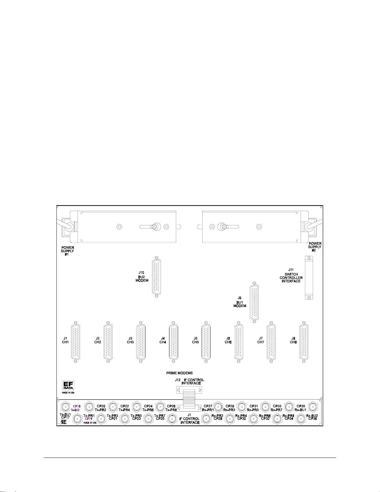
Ten modem data cable interfaces are located on the opposite face of the DSU (Figure
1-6); one for each of the eight prime and two backup satellite modems. Connectors J11
and J12 provide the interfaces for the SCU and IFU. The line cord receptacles for the
redundant power supply modules are located at the upper corners of the unit The springloaded mechanical slide, associated with each supply, must be slid aside to insert the AC
line cord. Unless the power cord is disconnected, this slide performs two functions
retaining the power cord and preventing the removal of the module.
Figure 1-6. DSU/IFU Modem Side
1–10 Rev. 3
Page 31

SMS-7000 Modem Protection Switch Introduction
1.2.3 IF Switch Unit (IFU)
All IF switching is performed in the IFU. In a typical application, the IFU is attached to
the DSU. If necessary, the unit can be mounted separately and interconnected with an
extended length interface cable. This procedure is recommended if mounting multiple
switches in the top of a rack or when separate mounting facilitates IF cabling.
The user has access to one downlink and one uplink port for each of the eight channels
(Figure 1-5).
Each prime and backup satellite modem in the configuration has an RX and TX coaxial
connection to the modem side of the DSU chassis (Figure 1-6).
Rev. 3 1–11
Page 32

Introduction SMS-7000 Modem Protection Switch
1.3 Specifications
Refer to Table 1-5 for operating specifications of the switch.
Table 1-5. SMS-7000 Specifications
Operation
Number of Service Channels Modular from 1 to 8. Field upgradeable; one data switch
module per channel.
Number of Backups 1 or 2.
Switching Modes Auto or Manual.
Backup Modes Dependent.
Independent (transmit/receive).
Modem Priority Programmable: high, medium, or low.
Configuration Control:
Remot e (programmable):
Type
EIA-485/232 with provisions for future support of standard
network interfaces.
Rate
Local
Control:
Front Panel
Remote
Front Panel LEDs:
Switch Status
Switch Fault
Modem Fault
Monitors:
Modulator Online Status
Demodulator Online Status
Switch Faults
110 to 19200 baud.
Menu-driven from the switch front panel, for both the switch
and the modems.
I/O Interfaces
Back-lit LCD display and keypad.
9-pin female D.
Power On.
Auto.
Manual.
System.
Equipment.
Stored.
Transmit.
Receive.
FORM-C relay outputs, 25-pin female D.
FORM-C relay outputs, 25-pin female D.
FORM-C relay outputs, 9-pin female D.
1–12 Rev. 3
Page 33

SMS-7000 Modem Protection Switch Introduction
Table 1-5. SMS-7000 Specifications (Continued)
I/O Interfaces
Terrestrial Data
(Each channel)
IF Ports 10 each IF Modulation: BNC.
IF Downlinks: up to 8.
Prime Power 90 to 264 VAC; 47 to 63 Hz, 40W max.
Size and Weight:
Control Unit
V.35 Data: 25-pin female D.
EIA-422/MIL-STD-188 Data: 37-pin female D.
G.703 Balanced Drop and Insert: 15-pin female D.
G.703 Unbalanced Drop and Insert: Coax.
EIA-232 Data: 25-pin female D.
ADPCM Audio Data: 9-pin female D.
Engineering Data Channel: 25-pin female D.
Alarms: 25-pin female D.
External Reference Clock: BNC.
10 each IF Demodulation: BNC.
8 each Uplinks: BNC.
8 each Downlinks: BNC.
Uplinks: up to 8.
Frequency response: 50 to 180 MHz.
Return loss: 18 dB.
Impedance: 75Ω or 50Ω (optional).
Isolation: 60 dB.
Transmit loss: < 1.5 dB.
Receive loss: < 5.0 dB.
General
-48 VDC; 40W max. optional.
1U 19-inch (48.3 cm) rack mount by 20-inch (51 cm) deep,
< 10 lbs. (4.5 kg).
Switch Unit with IF Switch
Mounting Top Mount.
Temperature:
Operating
Storage
Humidity
EMI CE-Mark certified.
8U 19-inch (48.3 cm) rack mount by approx. 4.5-inch deep
(11 cm), < 20 lbs. (9.1 kg).
Back Mount (Hinged).
0° to +40ºC (32° to 100°F).
-50° to +100ºC (-58° to 212°F).
95% at +40ºC (100°F), non-condensing.
Rev. 3 1–13
Page 34

Introduction SMS-7000 Modem Protection Switch
This page is intentionally left blank.
1–14 Rev. 3
Page 35

This chapter provides instructions for unpacking and installation, as well as external
connection information for the switch.
2.1 Unpacking
The switch (which consists of three sections) and the manual are packaged in preformed, reusable, cardboard cartons that contain foam spacing for maximum shipping
protection.
Do not use any cutting tool that will extend more than 1 inch (2.5 cm) into
the container and cause damage to the switch.
CAUTION
Chapter 2.
INSTALLATION
2
To remove the switch:
1. Cut the tape at the top of the carton (indicated by OPEN THIS END).
2. Remove the cardboard/foam packing covering the switch.
3. Remove the switch components, product manual, and power cords from the
carton.
4. Save the packing material for storage or reshipment purposes.
5. Inspect the equipment for any possible damage incurred during shipment.
6. Check the equipment against the packing list to ensure the shipment is correct.
Rev. 3 2–1
Page 36

Installation SMS-7000 Modem Protection Switch
2.2 Equipment Inspection
2.2.1 Included Parts
A typical switch contains the following components:
Note:
Parts are not drawn to scale.
Qty Description Qty Description
1 SMS-7000 Switch 1 Installation and Operation Manual
1 Cable Assembly, 37-Pin
Comtech EFData Part # PL/5361X
1 Cable Assembly, 15-pin M-15 pin
Comtech EFData Part No.
CA/5343-X
1 Envelope containing the test data
2–2 Rev. 3
Page 37

SMS-7000 Modem Protection Switch Installation
2.2.2 Back Mount (Hinged) Hardware Kit
1 Back Mount (Hinged) Hardware Kit (Comtech EFData Part # KT/5274), which includes:
Qty Description Qty Description
1 Base Hinge
8 10-32 x 1/2 Socket Head Cap Screws
Comtech EFData Part # FP/5151
1 Plate, Hinge Mounting
Comtech EFData Part # FP/5152-1
1 Plate, Hinge Mounting
Comtech EFData Part # FP/5152-2
1 Panel, Hinge Latch
Comtech EFData Part # FP/5153
2 Plate, Latch Striker
Comtech EFData Part # HW/10-32X1/2SH
8 #10 Flat Washer
Comtech EFData HW/10-FLT
4
10-32 x 3/8 Phillips Screw
Comtech EFData Part # HW/10-32X3/8 P.H.
2 Latch, Slam, 1/4 Turn, Black Knob
Comtech EFData Part # LATCH04
4 Spacer, 0.380 ID x 0.062 Thick, Fiber
Comtech EFData Part # 5154
1 Back Mount (Hinged) Hardware Kit (Comtech EFData Part # KT/5274), which includes:
Qty Description Qty Description
4 1/4-20 x 1/4 Socket Head Shoulder Screw
Comtech EFData Part #HW/1/420X1/4SHSS
Rev. 3 2–3
Comtech EFData Part # SPC380F062
Page 38

Installation SMS-7000 Modem Protection Switch
2.2.3 Top Mount Hardware Kit
1 Top Mounting Hardware Kit (Comtech EFData Part # KT/5275), which includes:
Qty Description Qty Description
2 Bracket, Rack Mounted IF Chassis
Comtech EFData Part # FP/5272
2 Bracket, Rack Mounted Switch
Chassis
6
4-40 x 3/8 Phillips Head Screw
Comtech EFData Part # HW/440X3/8P.H.
4 #10 Flat Washers
Comtech EFData Part # HW/10-FLT
Comtech EFData Part # FP/5273
4
10-32 x 3/8 Phillips Head Screw
Comtech EFData Part # HW/1032X3/8P.H.
6 #4 Flat Washers
Comtech EFData Part # HW/4-FLT
2–4 Rev. 3
Page 39

SMS-7000 Modem Protection Switch Installation
2.2.4 Cables
Notes:
1. The following QTY represents the minimum number of cables. Addition prime
and backup modems will require additional cables.
2. Contact Comtech EFData Sales department for information regrading the price
and availability of the cables.
1 Required cables for rack installation, include:
Qty Description Qty Description
1 Cable Assembly, Control,
w/Termination
2 Cable Assembly, 50-pin DSB (M to M)
Comtech EFData Part # CA/0755
4 Cable Assembly, IF BNC
Comtech EFData Part # CA/0813-X
Comtech EFData Part # CA/0737–X
Rev. 3 2–5
Page 40

Installation SMS-7000 Modem Protection Switch
2.2.5 Tools Required
Qty Description
1
3/8 inch (9 mm) drive ra tc he t.
1
3 x 3/8 inch (76 x 9 mm ) drive extension.
1
1/2 x 3/8 inch drive socke t.
6 pt.)
1
3/8 x 3/8 inch drive socke t.
9mm, 6 pt.)
1
1/4 x 3/8 inch drive socke t.
6mm, 6 pt.)
1 1/2 inch combination wrench.
13mm combination wrench with a 6 pt. box e nd.)
(Metric equivalent: 13mm,
(Metric equivalent:
(Metric equivalent:
(Metric equivalent:
2–6 Rev. 3
Page 41

SMS-7000 Modem Protection Switch Installation
2.3 Mounting
Prior to installing the switch in the customer equipment rack, an appropriate mounting
configuration must be defined. The switch components are designed for a variety of
mounting options to accommodate different user requirements.
The Switch Control Unit (SCU) chassis is a one unit (1U), 19-inch (48.3 cm) rackmountable unit intended for mounting at eye level in the front of the rack. The keypad
and display on the front panel of the SCU provide single-point control for all modems
associated with the switch, as well as for the switch.
The Data Switch Unit (DSU) and IF Unit (IFU) chassis may be mounted in various ways.
User application requirements determine which rack mounting option is used. The two
basic mounting locations are:
• Top mount
• Back mount
2.3.1 Description
2.3.1.1 Top Mount
This installation is intended for ceiling-routed cables, where terrestrial data harnesses
conveniently enter from the top of the rack. Installed on standard 19-inch (48.3 cm) rails
through an opening in the top of the rack, with the terrestrial interfaces facing up, this
configuration provides direct access to terrestrial data and IF ports at the top of the rack,
minimizing cabling within the rack.
2.3.1.2 Back Mount
This installation is intended for configurations where terrestrial data cables enter the top
and/or bottom of the rack. A back mount (hinge) kit is used to facilitate installation and
service access. The DSU and IFU are mounted directly inside the rear door of the rack.
The hinged switch chassis, when pitched out at the rear of the rack, provides access to
both the rear of the front panel-mounted equipment and the inside face of the switch.
Rev. 3 2–7
Page 42

Installation SMS-7000 Modem Protection Switch
2.3.2 Installation
2.3.2.1 Switch Control Unit
The Switch Control Unit (SCU) arrives fully assembled from the factory. After
unpacking the switch, install the switch control unit into the equipment rack and secure
with customer-furnished hardware.
2.3.2.2 Top Mount Installation
The Top Mount Hardware Kit (KT/5275) is for fixed-mounting the Data Switch Unit
(DSU) and Intermediate Frequency Switch Unit (IFU) to a standard equipment rack rails.
Kit components are listed in Section 2.2.
Although top mounting can be employed wherever there is clearance within the rack, it
provides a convenient external rack interface for both terrestrial data and IF signals that
are routed from the ceiling.
Assemble the DSU and IFU as shown in Figure 2-1 and as follows:
1. Install Bracket (FP/5272) on the IFU and secure with 6 screws and flat washers.
2. Install Bracket (FP/5273) onto the DSU and secure with 8 screws and flat
washers.
3. Position unit into the rack and secure with customer-furnished hardware.
2–8 Rev. 3
Page 43

SMS-7000 Modem Protection Switch Installation
Figure 2-1. Top Mount Installation
Rev. 3 2–9
Page 44

Installation SMS-7000 Modem Protection Switch
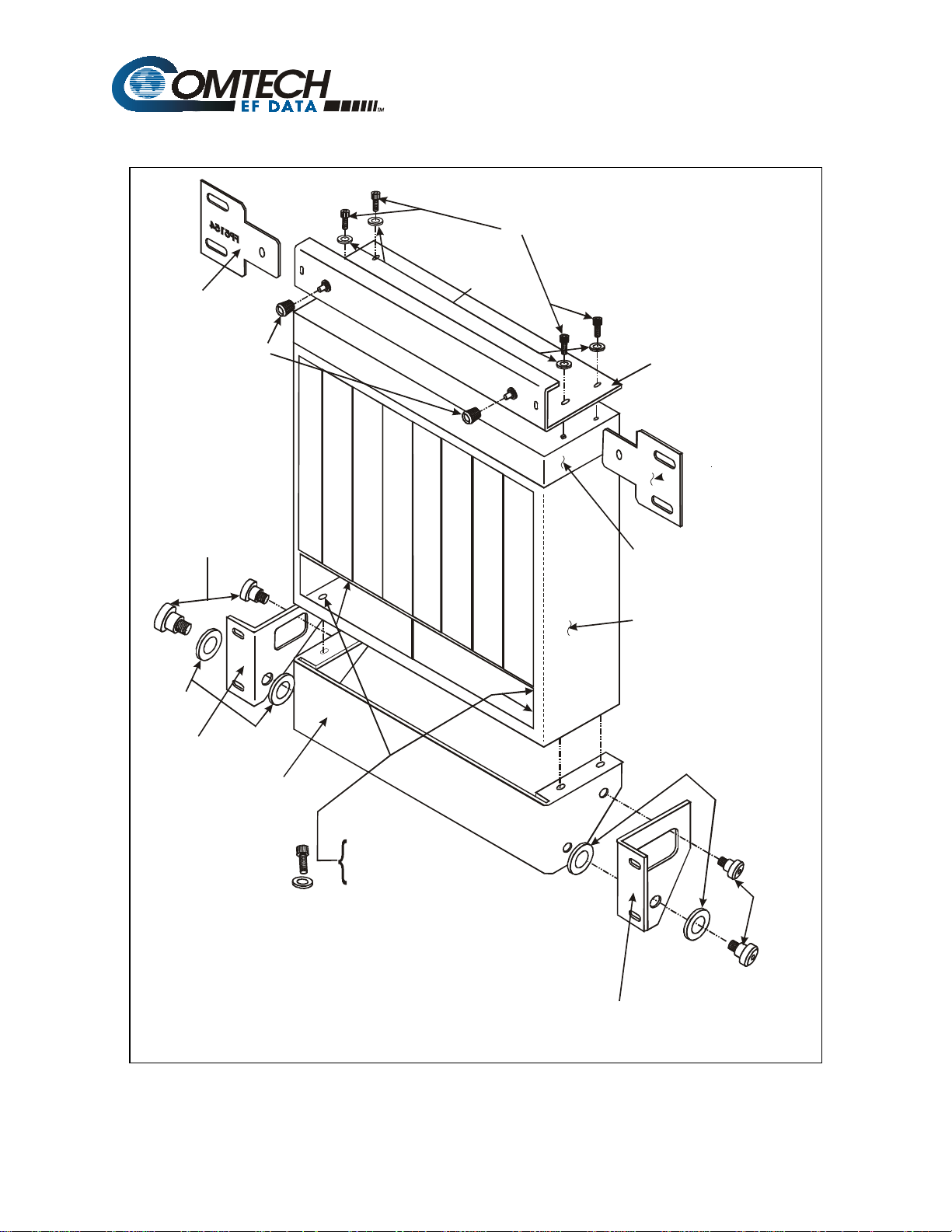
2.3.2.3 Back Mount Installation
The back mount (hinge) feature provides ready access for installation and service, while
making efficient use of rack volume. The Back-Mount Hardware Kit (KT/5274) is
intended for (but not restricted to) use in rear-mount applications where clearance and
access might create difficulty. Kit components are listed in Section 2.2.
The DSU and IFU must be secured prior to installation into the equipment rack. The
hinge is mounted to the attached base plate of the DSU). The latch plates are mounted to
the attached base plate. The DSU can be directly mounted behind the SCU and the
prime, and backup modems that it services.
Note:
This mounting requires the use of right-angle backshells for both the modem and
terrestrial data cables.
Assemble the DSU and IFU as shown in and as follows:
1. Position IFU on DSU and secure with four Phillips screws.
2. Install the Top Plate (FP/5153) to the IFU and secure with four 1/2-inch socket
screws and flat washers.
3. Install plates (FP/5154) to the equipment rack at the level to connect to the top
plate and secure with customer-furnished hardware.
4. Install base plate to the DSU and secure with four 1/2-inch socket screws and flat
washers.
5. Install right Plate (FP/5152-1) to the base plate and secure with two socket
screws and spacers.
6. Install left Plate (FP/5152-2) to the base plate and secure with two socket screws
and spacers.
7. Install the assembled DSU and IFU to the equipment rack and secure with
customer-furnished hardware.
2–10 Rev. 3
Page 45

SMS-7000 Modem Protection Switch Installation
Figure 2-2. Back Mount (Hinge) Installation
Rev. 3 2–11
Page 46

Installation SMS-7000 Modem Protection Switch
Figure 2-3. Hinge Mount, Side View
Figure 2-4. Hinge Mount, Top View
2–12 Rev. 3
Page 47

SMS-7000 Modem Protection Switch Installation
2.4 Cable Installation
2.4.1 Interconnecting the Switch Components
Refer to
Error! Reference source not found.
for typical cable installation.
The equipment rack is a mixed rack consisting of a SDM-6000 Satellite Modem serving
as the prime and a SDM-300 Satellite Modem incorporating the 50-pin data interface,
serving as the backup modem.
The SMS-7000 Switch is provided with two cables. All other cables are optional and the
customer should contact Comtech EFData Customer Support for price and availability.
Rev. 3 2–13
Page 48

Installation SMS-7000 Modem Protection Switch
(CA/5361)
(CA/5343)
SMS-7000 DSU/IFU Modem Side
TX Output
J6 Remo te
TM
CP20
CP19CP17
ADAPTIVE BROADBAND
(CA/0813-8)
(CA/0813-8)
(CA/0813-8)
CP18
(CA/0813-8)
TX/IFOUTPUT
CP1
TX Output
J6 Remote
J6 Remote
SDM-8000 PRIME #1
SDM-8000 PRIME #2
TX Output
J6 Remo te
SDM-8000 PRIME #3
TX/IF O u tput
CP3 CP1CP2
EXRE F RX/IF INPU T
J10
ALARMS
J9
AUX1
J6 Remo te
J7
FAULT
J6
REMOTE
SDM-300, 50 pin D Connector, Backup Modem
TM
ADAPTIVE BROADBAND
J6 J6 J4 J3 J2 J1
SMS-7000 SCU Rear Panel
Figure 2-5. Typical Switch Installation
2–14 Rev. 3
Page 49

SMS-7000 Modem Protection Switch Installation
2.4.1.1 SCU (J4) to DSU (J11) Interface
Refer to Figure 2-5.
Cable Assembly Part No. CA/5361 is provide with the switch. This is a single cable
interface between SCU Data Switch Interface J4 connector to the DSU Switch Controller
Interface J11 connector. The cable carries modem alarms, power supply faults, the serial
command link, and SCU power.
2.4.1.2 Remote Connection
Refer to Figure 2-5.
Option - Cable Assembly Part No. CA/0755 is offered by Comtech EFData. The remote
serial interface J6 connector of each modem in the configuration is bussed to the SCU
Modem Remote J2 connector.
This cable is a 9-pin D EIA-485 2-wire ribbon cable and must be connected before
programming the switch configuration. The cable assembly is configured for:
• Baud Rate: 9.6 to 19.2K
• 7 Information bits
• Parity: Even
• 2 Stop bits
Note:
Ensure the modems are all set to EIA-485 2-wire and that the baud rates match.
The ribbon cable assembly is used to query the configuration of modems, to set the
configuration of the backup modem, and to verify the saved configuration of the
modems. This data is used by the switch controller to set the position of the relays in the
data modules.
Rev. 3 2–15
Page 50

Installation SMS-7000 Modem Protection Switch
2.4.1.3 DSU (J12) to IFU (J1)
Refer to Figure 2-5.
Cable Assembly Part No. CA/5343 is provided with the switch. This is a single cable
interface between the two switching sections, J12 IF Control Interface on the DSU and
J1 IF Control Interface on the IFU. The cable carries EIA-485 at 9600 baud, control
signals, and power.
2.4.1.4 DSU J9 (BU1) Modem Connector to Backup Modem
Refer to Figure 2-5.
Option – Cable Part No. CA/0737 is offered by Comtech EFData. This 50-pin cable is
available in either straight hoods or right angle hoods. Refer to Table 2-1. This cable
includes two faults, Mod and Demod, pins 49 and 33. The modems will ground the two
pins when a No Fault condition exists. When either a Mod or Demod fault occurs, a line
will either Open, with the 50-pin cable pulled Off, or +5 VDC that is allowed from the
open collector fault circuit on the modem.
Table 2-1. 50-Pin Cable
Part No. Length, ft Type
CA/0737-2 2 Straight
CA/0737-4 4 Straight
CA/0737-4R 4 Right Angle
CA/0737-6 6 Straight
CA/0737-6R 6 Right Angle
CA/0737-8 8 Straight
CA/0737-8R 8 Right Angle
CA/0737-10 10 Straight
2.4.1.5 DSU JI CH to Prime Modem
Refer to Figure 2-5.
Option – Cable Part No. CA/0737 is offered by Comtech EFData.
2–16 Rev. 3
Page 51

SMS-7000 Modem Protection Switch Installation
2.4.1.6 IFU Connections (CP17 through CP36)
Refer to Figure 2-5.
Option – Cable CA/0813-8 is offered by Comtech EFData. Each prime and backup
modem in the configuration has an RX and TX coaxial connection to the modem face of
the IFU chassis. The switch and modems should have compatible characteristic IF
impedances of either 75Ω or 50Ω. Miniature coax is recommended to facilitate
harnessing.
2.5 Configuration Setup
This procedure will apply to the SDM-300, and current versions of the SDM-6000 and
SDM-8000 modems.
Note:
Communications shall be established between the switch controller and the
modems. No visual activity will occur, however, relays may click and fault lamps may
come on. Use UTILITY/MODEM CONTROL to take command of the operation.
2.5.1 Configure Rack Setup
Note:
The EIA-485 bus on the ribbon cable will be frozen if any communications are set
to EIA-232.
1. Check each modem for the following:
a. Remote Baud Rate: 9.6 or 19.2 kbit/s
b. Ribbon Cable: EIA-485 (2- or 4-wire)
c. Remote Address: Note
2. Check IF switch for the following:
a. Modem Remote Baud Rate: 9.6 or 19.2 kbit/s
b. Remote Address: Config the prime and backup modem to match.
Rev. 3 2–17
Page 52

Installation SMS-7000 Modem Protection Switch
3. Configure the switch controller, prime, and backup modems as follows:
a. Go to CONFIG/BACKUP #1 and insert all parameters.
Notes:
• DEPENDENT switching is preferred and it is the only function to
operate in the Drop and Insert application.
• The screen showing underlines will have to be filled in for the specific
modems that are to be backed up.
• If a modem in the switch is required, but not to be backed up, then leave
field blank.
• Turn MOD and DEMOD off on each prime modem, if the back up
modem is not to emulate the prime modem. The switch controller will
ignore the faults from the modem.
b. Configure the prime modems.
c. If Drop and Insert is the applications, then use Insert Clock as the RX Buffer.
Select LOOP that states; INSERT DATA INPUT LOOP or NORMAL.
Balance is for G.703 data cables that have different pairs.
d. Set LOAD ALL MODEMS. Fault lamps should go off.
4. Set switch mode from OPERATION to AUTO.
5. Backup modem should go into REMOTE.
6. Set switch screen to SYSTEM STATUS/SWITCHING.
7. Test the configured protection system as follows:
a. Crisscross the IF inputs on two prime modems.
b. Ensure the two modems transfer data to each other in the protection system.
c. Turn off the SDM-7000 switch to change data modules. If not, re-
initialization of the switch controller may result.
2–18 Rev. 3
Page 53

SMS-7000 Modem Protection Switch Installation
2.5.2 Trouble Shoot Configuration
Refer to Table 2-2 for trouble shooting information.
Table 2-2. Trouble Shooting
Problem Possible Cause Remedy
Load comes up with a MOD or DEMOD
configuration error.
A flashing number and the letter ‘F’
appears.
1. Switch controller not
communicating to the modems.
2. Backup modem cannot match all
the commands as the prime mode.
Reporting an open cable and is reporting
a fault.
Switch controller will query the modems
with a MCP and DCP command. Data
will be stored and compared with backup
modem. If no match, perform the
following:
1. Rack contains mixed modems. One
modem is high power and one is
normal power out. Set modems to
–5 dBm .
≤
2. Software version numbers are not
compatible. Upgrade the firmware
as necessary.
3. SDM-8000 is emulating an
SDM-6000 and SDM-300
emulating an SDM-6000.
Reconfigure rack with specific
modems. (SDM-8000 will backup
an SDM-6000, and the SDM-300
will backup SDM-300 modem.)
4. Ensure communications to the
modem are operational.
Backup modem will indicate a ‘B’ and
either a –, *, or ↑.
The – indicates; Backup modem is ready
to take command for a specific modem.
The * indicates; Backup modem is
undergoing remote configuration.
The ↑ indicates; Backup modem has
taken command for a specific prime
mode.
Rev. 3 2–19
Page 54

Installation SMS-7000 Modem Protection Switch
2.6 DSU Data Connections (J1 through J10)
There are 10 data cables between the modem face of the DSU and 10 possible modems
associated with the switch. Each of the eight prime modems has an associated data cable
connector, CH1 through CH8 (J1 through J8). The two backup modems are connected
with data cables to BU1 and BU2 (J9 and J10). The cable terminations are 50-pin male D
connectors. The signal/pin assignments, as they occur for each data configuration, are
listed in Table 2-3.
Table 2-3. DSU Data Connections (J1 through J10)
Signal Name
Overhead Type SDM-100 and No Overhead
Pin # IBS IDR D&I EIA-422 V.35 EIA-232
1 GND GND GND GND GND GND
2 GND GND GND
3 AGC-OUT AGC-OUT AGC-OUT
4 TXD-B 8K-TXO-A
5 TXD-A 8K-TXO-B
6 RXD-B 8K-RXO-A
7 RXD-A 8K-RXO-B
8 RS422RXO-A BWO1-C
9 RS422RXO-B BWO2-C
10 PRI-COM BWO3-C
11 SEC-COM BWO4-C
12 SCTE/TT-A BWI-1 TT-A SCTE-A TT
13 SCTE/TT-B BWI-2 TT-B SCTE-B
14 RS422TXO-A BWI-3
15 RS422TXO-B BWI-4
16 DF-COM
17 DMA
18 G703_SDB SD-B DDI-B
19 EXC-B EXC-B EXC_B EXC-B EXC-B
20 G703_RDB RD-B IDO-B
21 SCT/ST-A 8K-TXC-A ST-A SCT A ST
22 SCT/ST-B 8K-TXC-B ST-B SCT B
2–20 Rev. 3
Page 55

SMS-7000 Modem Protection Switch Installation
Table 2–3. DSU Data Connections (J1 through J10) (Continued)
Signal Name
Overhead Type SDM-100 and No Overhead
Pin # IBS IDR D&I EIA-422 V.35 EIA-232
23 SCR/RT-A 8K-RXC-A RT-A SCRA RT
24 SCR/RT-B 8K-RXC-B RT-B SCRB
25 TXCK BWO1-NC
26 RXCK BWO2-NC
27 PRI-NC BWO3-NC
28 SEC-NC BWO4-NC
29 RTS-B A1I-B RTS-B
30 RR-B A1O-B RR-B
31 CTS-B A2I-B CTS-B
32 DM-B A2O-B DM-B
33 DMD-FLT DMD-FLT DMD-FLT
34 G703_SDA SD-A DDI-A
35 EXC-A EXC-A EXC_A EXC-A EXC-A EXT CLK
36 G703_RDA RD-A IDO-A
37 SD-A 8K-TXD-A DDO-A SDA SD-A SD
38 SD-B 8K-TXD-B DDO-B SDB SD-B
39 RD-A 8K-RXD-A IDI-A RDA RD-A RD
40 RD-B 8K-RXD-B IDI-B RD-B RD-B
41 DSR/DM-A BWO1-NO
42 BWO2-NO
43 PRI-NO BWO3-NO
44 SEC-NO BWO4-NO
45 RTS-A A1I-A RTS-A RTS RTS
46 RLSD/RR-A A1O-A RR-A RLSD RR
47 CTS-A A2I-A CTS-A CTS CTS
48 DSR/DM-A A2O-A DM-A DSR DM
49 MOD-FLT MOD-FLT MOD-FLT
50 DF-NO
Rev. 3 2–21
Page 56

Installation SMS-7000 Modem Protection Switch
2.6.1 SCU Rear Panel
Refer to
Error! Reference source not found.
Figure 2-6. SCU Rear Panel
2.6.1.1 User Remote (J1)
This port is connected to a control device, such as a terminal or personal computer. The
control device then communicates with the switch and associated modems using the
protocol defined in Appendix A. The user remote interface can be an EIA-485 or EIA232, 110 to 19200 baud. The connector is a 9-pin female D with the pinouts as shown in
Table 2-4.
Table 2-4. User Remote EIA-485/EIA-232 Connector (J1)
Pin # 4-Wire 2-Wire
1 GND GND GND
2RD
3TD
4 +TX +RX/TX
5 -TX -RX/TX GND
6DSR
7RTS
8 +RX +RX/TX CTS
9-RX -RX/TX
.
EIA-485 EIA-232
2–22 Rev. 3
Page 57

SMS-7000 Modem Protection Switch Installation
2.6.1.2 Modem Remote (J2)
The modem remote interface is a 2-wire EIA-485, 9600, or 19200 baud. The connector is
a 9-pin female D, with the pinouts as shown in Table 2-5.
Table 2-5. Modem Remote EIA-485 Connector (J2)
Pin # Signal Name
1GND
2 Unused
3 Unused
4+RX/TX
5-RX/TX
6 Unused
7 Unused
8+RX/TX
9-RX/TX
2.6.1.3 Switch Faults (J3)
Switch fault outputs on this connector are provided by Form C relay contacts for status
monitoring.
• Controller Fault is indicated by a Common-to-Normally Closed contact closure,
activated if the controller loses power.
• M:N faults are indicated by a Common-to-Normally Open contact closure,
activated in the event of any fault registered in the Fault Alarm Menus.
Maximum relay contact current is 1A at 30 VDC.
The connector is a 9-pin female D with the pinouts as shown in Table 2-6.
Table 2-6. Switch Faults Connector (J3)
Pin # Signal Name
1 Controller Fault NO
2 Controller Fault COM
3 Controller Fault NC
4 M:N Fault NO
5 M:N Fault COM
6 M:N Fault NC
7 Spare 2 NO
8 Spare 2 COM
9 Spare 2 NC
Rev. 3 2–23
Page 58

Installation SMS-7000 Modem Protection Switch
2.6.1.4 Prime Mod (Online) Status (J6)
The prime mod (online) status to user connector provides Form C relay contact outputs
for status monitoring. Online is indicated by a Common-to-Normally-Closed contact
closure.
Maximum current is 1A at 30 VDC.
The connector is a 25-pin female D with the pinouts as shown in Table 2-7.
Table 2-7. Prime Mod Online Connector (J6)
Pin # Signal Name
1 MOD 1 COM
2 MOD 1 NC
3 MOD 1 NO
4 MOD 2 COM
5 MOD 2 NC
6 MOD 2 NO
7 MOD 3 COM
8 MOD 3 NC
9 MOD 3 NO
10 MOD 4 COM
11 MOD 4 NC
12 MOD 4 NO
13 MOD 5 COM
14 MOD 5 NC
15 MOD 5 NO
16 MOD 6 COM
17 MOD 6 NC
18 MOD 6 NO
19 MOD 7 COM
20 MOD 7 NC
21 MOD 7 NO
22 MOD 8 COM
23 MOD 8 NC
24 MOD 8 NO
25 SIGNAL GND
2–24 Rev. 3
Page 59

SMS-7000 Modem Protection Switch Installation
2.6.1.5 Prime Mod (Online) Status (J5)
The prime mod (online) status to user connector provides Form C relay contact outputs
for status monitoring. Online is indicated by a Common-to-Normally Closed contact
closure. Maximum current is 1A at 30 VDC.
The connector is a 25-pin female D with the pinouts as shown in Table 2-8.
Table 2-8. Prime Demod Online Connector (J5)
Pin # Signal Name
1DMD 1 COM
2DMD 1 NC
3DMD 1 NO
4DMD 2 COM
5DMD 2 NC
6DMD 2 NO
7DMD 3 COM
8DMD 3 NC
9DMD 3 NO
10 DMD 4 COM
11 DMD 4 NC
12 DMD 4 NO
13 DMD 5 COM
14 DMD 5 NC
15 DMD 5 NO
16 DMD 6 COM
17 DMD 6 NC
18 DMD 6 NO
19 DMD 7 COM
20 DMD 7 COM
21 DMD 7 NO
22 DMD 8 COM
23 DMD 8 NC
24 DMD 8 NO
25 SIGNAL GND
Rev. 3 2–25
Page 60

Installation SMS-7000 Modem Protection Switch
2.6.2 DSU Terrestrial Data Interfaces
Refer to Figure 2-7.
Up to eight switch modules support the following terrestrial data interfaces.
VR
.S
32
53
2
VR
.S
32
53
2
VR
.S
32
53
2
VR
.S
32
53
2
VR
.S
32
53
2
VR
.S
32
53
Figure 2-7. DSU/IFU Terrestrial Side
VR
.S
32
53
2
2
VR
.S
32
53
2
2–26 Rev. 3
Page 61

SMS-7000 Modem Protection Switch Installation
2.6.2.1 EIA-422/8 kbit/s Terrestrial Data (J6)
This data port is used for IBS-422 terrestrial data or IDR 8 kbit/s terrestrial overhead
data. The connector is a 37-pin female D, with one connector per channel (Table 2-9).
When using this port for IBS or no overhead data, be certain there is no
connection to the J1 (V.35) or J3 (G.703) ports. When using EIA-422 data,
CAUTION
all data switch modules must have jumper JP1 in EIA-422 position (with
jumpers connecting the middle pin and the pin closest to the front of the
switch module).
Table 2-9. EIA-422 Terrestrial Data Connectors (J6)
Signal Name
Pin # IBS IDR D&I
1 SHIELD SHIELD
2
3 RS422 TXO-A 8K TXO A
4 SD A 8K TXD A
5 ST A 8K TXC A
6 RD A 8K RXD A C
7 RTS A RTS A A
8 RT A 8K RXC A B
9 CTS A CTS A L
10 E
11 DM A N/C
12 R
13 RR A N/C E
14 M
15 EXC A 8K RXO A O
16 RS422 RXO A N/C V
17 TT A N/C E
18 D
19 GND GND
20 GND GND
21 RS422 TXO-B 8K TXO B
Rev. 3 2–27
Page 62

Installation SMS-7000 Modem Protection Switch
Table 2–9. EIA-422 Terrestrial Data Connectors (J6) (Continued)
Signal Name
Pin # IBS IDR D&I
22 SD B 8K TXD B
23 ST B 8K TXC B
24 RD B 8K RXD B
25RTS BRTS BA
26 RT B 8K RXC B L
27 CTS B CTS B
28
29 DM B N/C
30
31 RR B N/C
32
33 EXC B 8K RXO B
34 RS422 RXO B N/C
35 TT B N/C
36
37 GND GND
2–28 Rev. 3
Page 63

SMS-7000 Modem Protection Switch Installation
2.6.2.2 V.35/EIA-232-C Terrestrial Data (J1)
The V.35 terrestrial data connector (one of three IBS data options) is a 25-pin female D,
with one connector per channel (refer to Table 2-10).
When using this port, be certain there is no connection to the J6 (EIA-422)
or J3 (G.703) ports. When using EIA-232 data, all data switch modules
CAUTION
Pin # IBS V.35 IDR D&I EIA-232-C
1 SHIELD SHIELD
2SD A SD
3RD A RD
4RTS C C RTS
5CTS A A CTS
6DSR B B DM
7 SIG GND L L SIG GND
8RLSD E E RR
9 SCR B EXT CLK
10
11 SCTE B
12 SCT B R R
13 E E
14 SD B M M
15 SCT A O O ST
16 RD B V V
17 SCR A E E RT
18 D D
19
20 EXC A
21
22
23 EXC B
24 SCTE A (TT)
25 A
must have jumper JP1 in EIA-232 position (with jumpers connecting the
middle pin and the pin furthest from the front of the switch module). For
V.35, all jumpers must be in EIA-422 position.
Table 2-10. V.35/EIA-232 Terrestrial Data Connectors (J1)
Signal Name
Note:
For all eight switch modules, JP1 must be either set all EIA-232 or all
EIA-422/V.35/G.703 (JP1 set in the EIA-422/V.35/G.703 position works for most
applications).
Rev. 3 2–29
Page 64

Installation SMS-7000 Modem Protection Switch
2.6.2.3 Engineering Service Channel Data (J4)
The engineering service channel data connector is a 25-pin female D for IBS and D&I
data service. There is one connector per channel. The pinouts are shown in Table 2-11.
Table 2-11. Engineering Service Channel Data Connectors (J4)
Signal Name
Pin # IBS IDR D&I
1 SHIELD SHIELD
2 TXD A TXD A
3 RXD A RXD A
4 RTS/CTS C RTS/CTS
5 RTS/CTS A RTS/CTS
6 DSR B DSR
7 GND L GND
8E
9
10
11 R
12 E
13 M
14 TXD B O TXD B
15 TXCK V TXCK
16 RXD B E RXD B
17 RXCK D RXCK
18
19
20 EXC A
21
22
23 EXC B
24 SCTE A (TT)
2–30 Rev. 3
Page 65
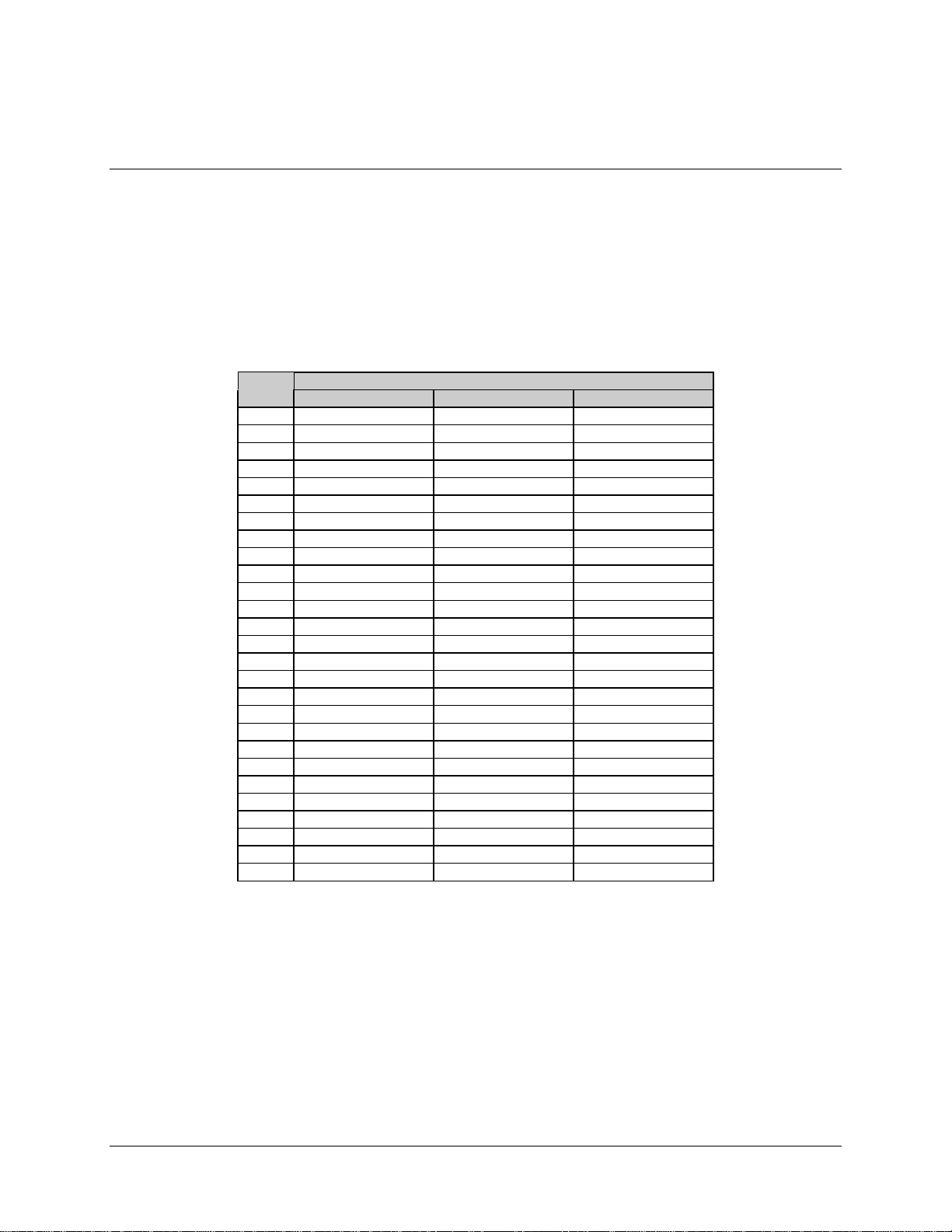
SMS-7000 Modem Protection Switch Installation
2.6.2.4 Alarms (J2)
The Alarms (J2) interface accommodates alarms as defined by IBS, IDR, and D&I data
formats. A relative demodulator signal strength (AGC_OUT) is also provided on this
connector. The alarms connector is a 25-pin female D with one connector per channel.
The pinouts are shown in Table 2-12.
Table 2-12. Alarms (J2) Connectors
Signal Name
Pin # IBS IDR D&I
1 N/C N/C N/C
2 N/C BWO1 C N/C
3 N/C BWO1 NC N/C
4 N/C BWO2 NO N/C
5 PROMPT COM BWO3 C PROMPT COM
6 PROMPT NC BWO3 NC PROMPT NC
7 SERVICE NO BWO4 NO SERVICE NO
8 N/C DF COM N/C
9 N/C DMA N/C
10 N/C BWI 2 N/C
11 N/C BWI 4 N/C
12 N/C N/C N/C
13 AGC_OUT AGC_OUT AGC_OUT
14 GND GND GND
15 N/C BWO1 NO N/C
16 N/C BWO2 C N/C
17 N/C BWO2 NC N/C
18 PROMP T NO BWO3 NO PROMPT NO
19 SERVICE COM BWO4 C SERVICE COM
20 SERVICE NC BWO4 NC SERVICE NC
21 N/C DF NO N/C
22 N/C BWI 1 N/C
23 N/C BWI 3 N/C
24 N/C N/C N/C
25 GND GND GND
26 RT B 8K RXC B L
27 CTS B CTS B
Rev. 3 2–31
Page 66

Installation SMS-7000 Modem Protection Switch
2.6.2.5 ADPCM Audio Data (J5)
The Adaptive Differential Pulse Code Modulation (ADPCM) audio data connector (as
defined for the IDR data format) is a 9-pin female D with one connector per channel. The
pinouts are shown in Table 2-13.
Table 2-13. ADPCM Audio Data (J5) Connectors
Signal Name
Pin # IBS IDR D&I 64K
1C A1I A C SDA
2O RA1O A O
3 N E GND N E GND
4N MA2I B N MSTB
5 E O A2O_B E O RDB
6C VA1I B C VSDB
7T EA1O B T ERTB
8O DA2I A O DSTA
9R A2O A R RDA
RRTA
2–32 Rev. 3
Page 67

SMS-7000 Modem Protection Switch Installation
2.6.2.6 Balanced G.703/Drop & Insert Data (J3)
Primary data for IDR and D&I as well as one of three IBS data options (balanced
G.703/D&I data connector) is facilitated by using a 15-pin female D with one connector
per channel. The pinouts are shown in Table 2-14.
When using this port for other than IDR data, be certain there is no
connection to the J6 (EIA-422) or J1 (V.35) ports. When using G.703 data,
CAUTION
Table 2-14. Balanced G.703/Drop & Insert Data Connectors (J3)
all data switch modules must have jumper JP1 in EIA-422 position (with
jumpers connecting the middle pin and the pin closest to the front of the
switch module).
Signal Name
Pin # IBS IDR D&I
1 SD A SD A DDI-A
2 GND GND GND
3 RD A RD A IDO-A
4 GND GND GND
5 Open Open DDO-B
6 Open Open IDI-B
7 EXC_A EXC_A EXC_A
8 EXC_B EXC_B EXC_B
9 SD B SD B DDI-B
10 Open Open Open
11 RD B RD B IDO-B
12 Open Open DDO-A
13 Open Open IDI-A
14 Open Open Open
15 Open Open Open
Rev. 3 2–33
Page 68

Installation SMS-7000 Modem Protection Switch
2.6.2.7 Unbalanced Data Ports
Unbalanced data ports on 75Ω BNC coax connectors contain G.703, D&I, and external
clock signals. These data ports also facilitate IBS, D&I, or IDR data. When selected from
the control panel, the Unbalanced External Clock replaces the external clock signals on
J1, J3, and J6. The pinouts are shown in Table 2-15.
When using the G.703 unbalanced data ports for other than IDR data, be
certain there is no connection to the J6 (EIA-422) or J1 (V.35) ports. When
CAUTION
using G.703 data, all data switch modules must have jumper JP1 in
EIA-422 position (with jumpers connecting the middle pin and the pin
closest to the front of the switch module).
Table 2-15. Unbalanced Data Connectors
Signal Name
Pin # IBS IDR D&I
CP1 G.703 SD G.703 SD DDI
CP2 G.703 RD G.703 RD IDO
CP3 Open Open DDO
CP4 Open Open IDI
CP5 EXC EXC EXC
2–34 Rev. 3
Page 69

SMS-7000 Modem Protection Switch Installation
2.6.3 IFU Uplink and Downlink IF (CP1 through CP16)
Each of eight channels has dedicated uplink and downlink ports located on the IFU, as
shown in Table 2-16. These ports are BNC female, either 50Ω, or 75Ω, as required.
Table 2-16. IFU Uplink/IF Downlink Data Connectors
Connector
Reference
CP1 CH1 Uplink
CP2 CH2 Uplink
CP3 CH3 Uplink
CP4 CH4 Uplink
CP5 CH5 Uplink
CP6 CH6 Uplink
CP7 CH7 Uplink
CP8 CH8 Uplink
CP9 CH1 Downlink
CP10 CH2 Downlink
CP11 CH3 Downlink
CP12 CH4 Downlink
CP13 CH5 Downlink
CP14 CH6 Downlink
CP15 CH7 Downlink
CP16 CH8 Downlink
Signal
Rev. 3 2–35
Page 70

Installation SMS-7000 Modem Protection Switch
This page is intentionally left blank.
2–36 Rev. 3
Page 71

This chapter defines the controls and procedures for configuration and operation of the
protection switch.
Note:
Familiarization with the front panel controls (Figure 3-1) and/or the related remote
commands described in Appendix A is recommended.
3.1 Configuration
The configuration of the protection switch may be performed from the front panel, or
from a terminal or personal computer connected to the protection switch remote port
(J1).
Chapter 3.
OPERATION
3
Each front panel menu screen has corresponding remote commands. The front panel
display menus are designed to guide the operator through the configuration process.
Note:
Refer to the menu tables presented in this chapter for specific configuration
information.
Figure 3-1. SMS-7000 Front Panel View
Rev. 3 3–1
Page 72

Operation SMS-7000 Modem Protection Switch
3.1.1 Backup Modems
The configuration of the backup modems (1 or 2) is usually performed first. Each backup
is defined to switch either independently or dependently, as a function of RX or TX
faults in the assigned prime modems.
A set of prime modems can be assigned using the backup configuration menu (refer to
Figure 3-3). Individual prime MOD and DEMOD priority and delay options are available
when the backup modem is intended to backup the MOD and DEMOD independently.
The independent backup will only backup the modems that are selected in the set under
the ‘Backup #n Prime Modems’ menu.
3.1.2 Prime Modems
When progressing into the prime modem (1 through 8) configuration menus, two
possible menu sets are available: independent or dependent.
• If assigned to a backup designated as independent, the modem configuration
menu set provides for setting the TX and RX parameters independently.
• If assigned to a dependent backup, no distinction is made between RX and TX in
the menu.
3.2 Front Panel
The protection switch front panel (Figure 3-1) provides a local interface to configure,
operate, and monitor the switch. For remote control operation information, refer to
Appendix A.
The front panel features:
• 48-character, 2-line, back-lit Liquid Crystal Display (LCD).
• 6-key, user friendly keypad that provides a wide variety of functions.
• 8 Light-Emitting Diodes (LEDs) on the front panel to provide overall status at a
glance.
3–2 Rev. 3
Page 73

SMS-7000 Modem Protection Switch Operation
3.2.1 LED Indicators
The eight LEDs on the front panel indicate the following (see Table 3-1):
Table 3-1. LED Indicators
Name LED Description
Status
Power On Green Indicates that power is applied to the switch.
Auto Green Indicates the switch is automatically assigning backup modems.
Manual Green Indicates the backup modems are being assigned as d i rected by the user
from the manual menu.
Switch Fault
System Red Indicates a communications failure or a configuration anomaly between
the switch and the attached modems. Specifics are displayed in the
Fault/Alarm menu. For example, mixing modems (without paying
attention to Table 1-1) in a rack will cause this fault, due to differences in
the remote communications commands.
Equipment Red Indicates a communications failure between the switch modules or a
detected fault within the switch hardware. Specifics are displayed in the
Fault/Alarm menu. For example, a power supply not plugged in will
indicate this fault.
Stored Yellow Indicates that a fault occurrence has been logged and stored. Specifics are
displayed in the Stored Fault/Alarms menu.
The fault may or may not be active.
Transmit Yellow Indicates a faulted prime modulator which has not been backed up. The
identity of the faulted modem(s) is displayed in the switch Fault/Alarm
menu. Specifics are displayed in the Fault/Alarm menu of the individual
modems. This fault clears when the faulted prime is backed up or when
the fault is removed.
Receive Yellow Indicates a faulted prime demodulator which has not been backed up. The
identity of the faulted modem(s) is displayed in the switch Fault/Alarm
menu. Specifics are displayed in the Fault/Alarm menu of the individual
modems. This fault clears when the faulted prime is backed up, or when
the fault is removed.
Rev. 3 3–3
Page 74

Operation SMS-7000 Modem Protection Switch
3.2.2 Front Panel Controls
The switch is locally operated by using the front panel keypad, which consists of the
following keys (see Table 3-2):
Table 3-2. Front Panel Keypad
Key Description
[ENTER] This key is u sed to select a displayed fun ction, or to execute a change to the
configuration.
[CLEAR] This key is used to back out of a selection, or to cancel a configuration change
which has not been executed by pressing [ENTER].
Pressing [CLEAR] generally returns the display to the previous selection.
[←] and [→]
[↑] and [↓]
These keys are used to move to the next sel ect ion, or to move the cursor for certain
functions.
These keys are used primarily to change configuration data (numbers), but are al so
used at times to move from one section to another.
Whenever a key is pressed, the switch responds with a beep:
• A single beep indicates a valid entry (the appropriate action was taken).
• A double beep indicates an invalid entry.
3–4 Rev. 3
Page 75

SMS-7000 Modem Protection Switch Operation
3.3 Menu System
Refer to Figure 3-2 through Figure 3-12 to access and execute all functions. Use the main
menu in Figure 3-2 as a quick reference for accessing the protection switch functions.
Refer to Section 3.2 for further configuration details.
When the protection switch power is turned ON, the base level of the menu system
displays the sign-on message:
• Line 1 of the sign-on message is the protection switch model number and type.
• Line 2 is the version number of the firmware.
The main level of the menu system is Function Select. To access this level from the
sign-on message, press the [←] or [→] keys. From the Function Select menu, select one
of the functional categories:
• Configuration
• System Status
• Faults/Alarms
• Stored Faults/Alarms
• Utility
Press [←] or [→] to move from one selection to another. When line 2 displays the
desired function, select that level by pressing [ENTER]. After entering the appropriate
functional level, press [←] or [→] to move to the desired function.
To view or change the configuration of the protection switch, enter the Configuration
level from the Function Select menu. While in the Configuration menu, press [←] or [→]
to scroll through the Configuration menu selection.
Press [ENTER] to select the desired Configuration menu option. To view the options for
the selected configuration parameters, press [←] or [→]. To change a configuration
parameter, press [ENTER] to begin the change process.
Press [↑] or [↓] to change the parameters. After the correct parameters are displayed,
press [ENTER] to execute the change. This action initiates the necessary programming
by the protection switch. To undo a parameter change prior to execution, press
[CLEAR].
Notes:
1. Figure 3-2 through Figure 3-12 show the front panel menu window selections.
2. Menus or commands that are specific to certain protection switch configurations
are only accessible after selecting the appropriate protection switch
configuration. This prevents incompatible parameters from accidentally being
selected.
Rev. 3 3–5
Page 76

Operation SMS-7000 Modem Protection Switch
This page is intentionally left blank.
3–6 Rev. 3
Page 77

SMS-7000 Modem Protection Switch Operation
3.4 Front Panel Menu
SMS-7000 "TYPE"
VER: 2.1.8
FUNCTION SELECT
CONFIGURATION
CONFIGURATION
BACKUP #1 or 2
(Figure 3-3)
CONFIGURATION
INDEPENDENT
PRIME #1 through 8
(Figure 3-4)
CONFIGURATION
DEPENDENT
PRIME # 1 through 8
(Figure 3-5)
CONFIGURATION
LOAD/VERIFY
(Figure 3-6)
CONFIGURATION
OPERATION MODE
(Figure 3-7)
FUNCTION SELECT
SYSTEM STATUS
SYSTEM STATUS
SWITCHING
(Figure 3-8)
SYSTEM STATUS
CONFIGURATION
(Figure 3-9)
FUNCTION SELECT
FAULTS/ALARMS
(Figure 3-10)
FUNCTION SELECT
STORED FLTS/ALARMS
(Figure 3-11)
FUNCTION SELECT
UTILITY
UTILITY
SYSTEM
(Figure 3-12)
Figure 3-2. Main Menu
Rev. 3 3–7
Page 78

Operation SMS-7000 Modem Protection Switch
SMS-7000
VER: X.X.X
BACKUP MODEM #n
ADDRESS: xxx
n = 1 or 2
xxx = 0 through 255
BACKUP #n
PRIME MODEMS
n n n n n n n n
Toggling each 'n' digit
assigns or deassigns prime
modems 1-8 respectively.
An '_' is
displayed when not
assigned.
Manual mode only
if 'INDEPENDENT'.
Status window.
FUNCTION SELECT
CONFIGURATION
BACKUP MOD #n BACKUP DEMOD #n
ON
OFF
n = 1 or 2
Manual mode only.
BACKUP #n
MULTIPLEXER
YES/NO
n = 1 to 2
If 'YES', M-2000 multiplexer
is attached.
BACKUP #n
MULTIPLEXER
ADDRESS: nnn
n = 0, 1 or 2
nnn =1 to 255
(0 removes multiplexer
from system)
Displayed only when
M-2000 multiplexer is
attached and selected.
CONFIGURATION
BACKUP #1 AND #2
Manual mode only.
ON
OFF
n = 1 or 2
Key:
ACCESS TO
SUBMENU
BACKUP #n
SWITCHING MODE
INDEPENDENT
DEPENDENT
n = 1 or 2
CONDITIONAL OR
OPTION-DEPENDENT
Parameter Information
Figure 3-3. Configuration Backup 1 and 2 Menu
3–8 Rev. 3
Page 79

SMS-7000 Modem Protection Switch Operation
3.4.1 Configuration Backup 1 and 2 Menu
Refer to Figure 3-3.
BACKUP MODEM #n
ADDRESS
BACKUP MOD #n Turn On or Off the switch to recognize that the Backup modulator
BACKUP DEMOD #n Turn On or Off the switch to recognize that the Backup
BACKUP #n SWITCHING
MODE
BACKUP #n PRIME
MODEMS
Set # other than 0. Numbers 9 or 10 are recommended when the
protection system is full; two backups and eight prime modems.
Address: 0 to 255.
Note:
Address 0 is reserved as a global address.
Upon entry, the current status is displayed. Press [↑] or [ ↓] to
make the selection. Press [ENTER] to execut e the change.
status.
Upon entry, the current status is displayed. Press [↑] or [ ↓] to
make the selection. Press [ENTER] to execut e the change.
demodulator status.
Upon entry, the current status is displayed. Press [↑] or [ ↓] to
make the selection. Press [ENTER] to execut e the change.
When a failure occurs, DEPENDENT mode switching will place
the whole Prime modem to the Backup modem. When a failure
occurs, INDEPENDENT switching will only switch half the
modem; either the Modulator or the Demodulator.
Upon entry, the current status is displayed. Press [↑] or [ ↓] to
make the selection. Press [ENTER] to execut e the change.
Place the Prime modem numbers in the spaces provided so that the
Backup modem will only look to backup the identified prime
modems.
e.g., 1 _ 3 _ 5 _ _ _. This example displays the Backup modem
replacing modem #s 1, 3, and 5.
Upon entry, the current status is displayed. Press [↑] or [ ↓] to
make the selection. Press [ENTER] to execut e the change.
BACKUP #n
MULTIPLEXER
BACKUP #n
MULTIPLEXER
ADDRESS
Rev. 3 3–9
Used when the Comtech EFData M-2000 multiplexer is included in
the modem set-up.
Upon entry, the current status is displayed. Press [↑] or [ ↓] to
make the selection. Press [ENTER] to execut e the change.
Display status of multiplexer: ‘YES or NO’.
Upon entry, the current status is displayed. Press [↑] or [ ↓] to
make the selection. Press [ENTER] to execut e the change.
Page 80

Operation SMS-7000 Modem Protection Switch
SMS-7000
VER: X.X.X
PRIME MODEM #n
ADDRESS: xxx
n = 1 through 8
xxx = 0 through 255
0 removes prime modem
from system.
PRIME DEMOD #n
ON
OFF
n = 1 through 8
Manual mode only.
Key:
ACCESS TO
SUBMENU
FUNCTION SELECT
CONFIGURATION
PRIME #n
MULTIPLEXER
ADDRESS: xxx
n = 1 through 8
xxx = 0 to 255
Displayed only if
'YES' is selected in
the previous window.
CONDITIONAL OR
OPTION-
DEPENDENT
PRIME MOD #n
ON
OFF
n = 1 through 8
Manual mode only.
PRIME DEMOD #n
PRIORITY
HIGH
MEDIUM
LOW
n = 1 through 8
Parameter
Information
CONFIGURATION
INDEPENDENT
PRIME #n
PRIME MOD #n
PRIORITY
HIGH
MEDIUM
LOW
n = 1 through 8
PRIME DEMOD #n
DELAY
NONE
AUTO
MANUAL
n = 1 through 8
BREAKOUT #n
D & I
BALANCED
UNBALANCED
PRIME MOD #n
DELAY
NONE
MANUAL
n = 1 through 8
PRIME #n
MULTIPLEXER
YES
NO
n = 1 through 8
If 'YES',
the following selection
will be displayed.
BREAKOUT #n
CONFIGURATION
n = 1 through 8
BREAKOUT #n
EXTERNAL CLOCK
BALANCED
UNBALANCED
BREAKOUT #n
INSERT DATA INPUT
LOOP
NORMAL
Used for tying DDO to
IDI for using insert
clock as the buffer
clock source
Figure 3-4. Configuration Independent Prime 1 through 8 Menu
3–10 Rev. 3
Page 81

SMS-7000 Modem Protection Switch Operation
3.4.2 Configuration Independent Prime 1 through 8 Menu
Refer to Figure 3-4.
PRIME MODEM #n
ADDRESS
PRIME MOD #n Must be On for the switch to recognize it as active.
PRIME MOD #n
PRIORITY
PRIME MOD #n DELAY NONE
PRIME DEMOD #n Must be On for the switch to recognize it as active.
PRIME DEMOD #n
PRIORITY
PRIME DEMOD #n
DELAY
Set # other than 0. Address 0 is a global address which is used to
communicate with all modems even though the address is set to
something else.
Address: 0 to 255
Upon entry, the current status is displayed. Press [↑] or [ ↓] to make
the selection. Press [ENTER] to execute the change.
Upon entry, the current status is displayed. Press [↑] or [ ↓] to make
the selection. Press [ENTER] to execute the change.
Options: LOW, MEDIUM, and HIGH.
Upon entry, the current status is displayed. Press [↑] or [ ↓] to make
the selection. Press [ENTER] to execute the change.
MANUAL = 0.5 to 127.0 SEC.
Upon entry, the current status is displayed. Press [↑] or [ ↓] to make
the selection. Press [ENTER] to execute the change.
Upon entry, the current status is displayed. Press [↑] or [ ↓] to make
the selection. Press [ENTER] to execute the change.
Options: LOW, MEDIUM, and HIGH.
Upon entry, the current status is displayed, Press [↑] or [ ↓] to make
the selection. Press [ENTER} to execute the change.
NONE
AUTO
MANUAL = 0.5 to 127.0 SEC.
Upon entry, the current status is displayed. Press [↑] or [ ↓] to make
the selection. Press [ENTER] to execute the change.
PRIME #n
MULTIPLEXER
PRIME DEMOD #n
MULTIPLEXER
ADDRESS
(Menu applies, only if
multiplexer is attached.)
Rev. 3 3–11
Displayed if multiplexer is; ‘YES or NO.’
Upon entry, the current status is displayed. Press [↑] or [ ↓] to make
the selection. Press [ENTER] to execute the change.
Set # other than 0. Address 0 removes the multiplexer from the
system.
Address: 0 to 255
Upon entry, the current status is displayed. Press [↑] or [ ↓] to make
the selection. Press [ENTER] to execute the change.
Page 82

Operation SMS-7000 Modem Protection Switch
BREAKOUT #n
CONFIGURATION
D & I Use the BNC connectors for Unbalanced.
EXTERNAL CLOCK Use the BNC connectors for Unbalanced.
INSERT DATA INPUT Options: NORMAL or LOOP
Press [ENTER] to access submenus.
Use the DB15 connecto r for Balanced.
Use the DB15 connecto r for Balanced
Loop will connect DDO to IDI for D & I operation. This allows
operator to select “in sert clock” as the buffer clock source.
3–12 Rev. 3
Page 83

SMS-7000 Modem Protection Switch Operation
This page is intentionally left blank.
Rev. 3 3–13
Page 84

Operation SMS-7000 Modem Protection Switch
SMS-7000
VER: X.X.X
PRIME MOD #n PRIME DEMOD #n
ON
OFF
n = 1 through 8
Manual mode only.
PRIME #n
MULTIPLEXER
YES
NO
n = 1 through 8
If 'YES',
the following selection
will be displayed.
FUNCTION SELECT
CONFIGURATION
ON
OFF
n = 1 through 8
Manual mode only.
PRIME #n MULTIPLEXER
ADDRESS: xxx
n = 1 through 8
xxx = 0 to 255
Displayed only if
'YES' is selected in
the previous window.
CONFIGURATION
DEPENDENT
PRIME #n
PRIME MOD #n
PRIORITY
HIGH
MEDIUM
LOW
n = 1 through 8
BREAKOUT #n
D & I
BALANCED
UNBALANCED
PRIME MOD #n
DELAY
NONE
AUTO
MANUAL
n = 1 through 8
BREAKOUT #n
CONFIGURATION
n = 1 through 8
BREAKOUT #n
EXTERNAL CLOCK
BALANCED
UNBALANCED
BREAKOUT #n
INSERT DATA INPUT
LOOP
NORMAL
Used for tying DDO to
IDI for using insert
clock as the buffer
clock source
Key:
ACCESS TO
SUBMENU
CONDITIONAL OR
OPTION-
DEPENDENT
Parameter
Information
Figure 3-5. Configuration Dependent Prime 1 through 8 Menu
3–14 Rev. 3
Page 85

SMS-7000 Modem Protection Switch Operation
3.4.3 Configuration Dependent Prime 1 through 8 Menu
Refer to Figure 3-5.
PRIME MODEM #n
ADDRESS
PRIME MOD #n Must be On for the switch to recogn i ze as active.
PRIME DEMOD #n Must be On for the switch to recognize as active.
PRIME MODEM #n
PRIORITY
PRIME MODEM #n
DELAY
PRIME #n MULTIPLEXER Displayed if multiplexer is; ‘YES or NO.’
Set # other than 0. Address 0 is a global address.
Upon entry, the current status is displayed. Press [↑] or [ ↓] to make
the selection. Press [ENTER] to execute the change.
Upon entry, the current status is displayed. Press [↑] or [ ↓] to make
the selection. Press [ENTER] to execute the change.
Upon entry, the current status is displayed. Press [↑] or [ ↓] to make
the selection. Press [ENTER] to execute the change.
Options: LOW, MEDIUM, and HIGH.
Upon entry, the current status is displayed. Press [↑] or [ ↓] to make
the selection. Press [ENTER] to execute the change.
AUTO = 2 times sweep period
MANUAL = 0.5 to 127.0 SEC.
To switch properly in DEPENDENT mode, the Prime modem demods
must have input from a source modem other than their own. Otherwise,
when the delay is set to NONE, the switch will oscillate between prime
and backup modems. This occurs because the output of the modulator
has been interrupted while the whole modem attempts to switch.
Upon entry, the current status is displayed. Press [↑] or [ ↓] to make
the selection. Press [ENTER] to execute the change.
Upon entry, the current status is displayed. Press [↑] or [ ↓] to make
the selection. Press [ENTER] to execute the change.
PRIME DEMOD #n
MULTIPLEXER
ADDRESS
(Menu applies, only if
multiplexer is attached.)
BREAKOUT #n
CONFIGURATION
D & I Use the BNC connectors for Unbalanced.
EXTERNAL CLOCK Use the BNC connectors for Unbalanced.
INSERT DATA INPUT Options: NORMAL/LOOP
Rev. 3 3–15
Set # other than 0. Address 0 removes the multiplexer from the system.
Address: 0 to 255
Upon entry, the current status is displayed. Press [↑] or [ ↓] to make
the selection. Press [ENTER] to execute the change.
Press [ENTER] to access submenus.
Use the DB15 connecto r for Balanced.
Use the DB15 connecto r for Balanced.
Select LOOP if insert clock is sel ected as receive buffer clock source at
the modem. This connects DDO to IDI. (Drop Data Out to Insert Data
In).
Page 86

Operation SMS-7000 Modem Protection Switch
SMS-7000
VER: X.X.X
LOAD PRIME MODEM
n
n = 1 through 8 n = 1 through 8
VERIFY BACKUP
MODEM n
n = 1 or 2
FUNCTION SELECT
CONFIGURATION
LOAD BACKUP
MODEM n
n = 1 or 2
VERIFY ALL
MODEMS
PRESS ENTER
TO VERIFY
All backup modems and
Prime modems
that are 'active'.
CONFIGURATION
LOAD/VERIFY
LOAD ALL MODEMS
PRESS ENTER
TO LOAD
All Backup modems and
Prime modems that
are 'active'.
VERIFY PRIME
MODEM n
Key:
ACCESS TO
SUBMENU
CONDITIONAL OR
OPTION-
DEPENDENT
Parameter
Information
Figure 3-6. Configuration Load/Verify Menu
3–16 Rev. 3
Page 87

SMS-7000 Modem Protection Switch Operation
3.4.4 Configuration Load/Verify Menu
Refer to Figure 3-6.
LOAD PRIME MODEM n Active modems only (use if configuration changes have
been made for any one prime modem).
LOAD BACKUP MODEM n Active modems only (use if configuration changes have
been made to all prime modems).
LOAD ALL MODEMS Active modems only.
Press [ENTER] twice to load.
VERIFY PRIME MODEM n Active modems only (used to verify that the modem
configuration has not changed).
VERIFY BACKUP MODEM n Active modems only.
VERIFY ALL MODEMS Active modems only.
Press [ENTER] twice to verify.
Rev. 3 3–17
Page 88
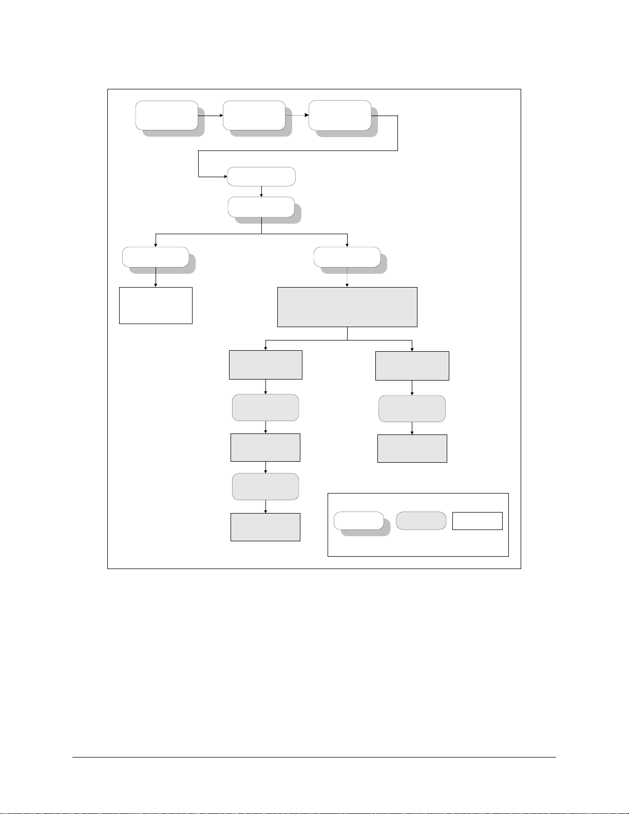
Operation SMS-7000 Modem Protection Switch
SMS-7000
VER: X.X.X
AUTO MANUAL
AUTO - Allows the
backup modem to replace
the prime modem
automatically.
FUNCTION SELECT
CONFIGURATION
OPERATION MODE
AUTO
MANUAL
MANUAL - Enables submenus for direct control of
Backups # 1 or 2
Independent
BACKUP #1 MOD
BACKUP PRIME
MODEM: n
the protection switch. The submenu displayed
depends on the switiching mode of the current
backup modem (Independent or Dependent).
CONFIGURATION
OPERATION MODE
Backups # 1 or 2
Dependent
BACKUP #1
MODEM, BACKUP
PRIME MODEM: n
n = 0, or 1 to 8
Enter 1 to 8 for online,
0 for off-line.
BACKUP #1 DEMOD
BACKUP PRIME
MODEM: n
n = 0, or 1 to 8
Enter 1 to 8 for online,
0 for off-line.
Key:
ACCESS TO
SUBMENU
n = 0, or 1 to 8
Enter 1 to 8 for online,
0 for off-line.
CONDITIONAL OR
OPTION-
DEPENDENT
Figure 3-7. Configuration Operation Mode Menu
Parameter
Information
3–18 Rev. 3
Page 89

SMS-7000 Modem Protection Switch Operation
3.4.5 Configuration Operation Mode Menu
Refer to Figure 3-7.
Operation Mode AUTO or MANUAL
If ‘AUTO’, the Backup modem automatically replaces
the failed Prime modems.
If ‘MANUAL’, a submenu is enabled for direct
control of the protection switch. The submenu
displayed depends on the switching mode of the
current backup modem; i.e., INDEPENDENT or
DEPENDENT.
Upon entry, the current status is displayed. Press [↑]
or [ ↓] to make the selection. Press [ENTER] to
execute the change.
Rev. 3 3–19
Page 90

Operation SMS-7000 Modem Protection Switch
SMS-7000
VER: X.X.X
FUNCTION SELECT
SYSTEM STATUS
MOD mmmmmmmm Byxn Bzxn
DMD dddddddd Byxn Bzxn
Figure 3-8. System Status Switching Menu
SYSTEM STATUS
SWITCHING
MOD mmmmmmmm
By xxxxx n Bz xxxxx n
Status Window
Key:
ACCESS TO
SUBMENU
CONDITIONAL OR
OPTION-
DEPENDENT
DEMOD dddddddd
By xxxxx n Bz xxxxx n
Status WindowStatus window.
Parameter
Information
3–20 Rev. 3
Page 91

SMS-7000 Modem Protection Switch Operation
3.4.6 System Status Switching Menu
Refer to Figure 3-8.
MOD mmmmmmmm Byxn Bzx n
DMD dddddddd Byxn Bzxn
MOD mmmmmmmm
By xxxxx n Bz xxxxx n
DEMOD dddddddd
By xxxxx n Bz xxxxx n
Status window.
Displays summary of active prime Mods and online backup Mods on
Line 1.
Displays summary of active prime Demods and online backup Demods
on Line 2.
If a prime or backup Mod/Demod i s faul t ed, an “F” alternates with
Mod/Demod n # on display.
Where:
Mmmmmmmm = 1 thro ugh 8 acti ve prime Mods/D emods .
– = Not active.
y = 1 backup Mod/Demod.
z = 2 backup Mod/Demod.
x = – if backup Mod/Demod is not online or HOT STANDBY.
x = -> indicates prime Mod/Demod being backed up.
x is blinking '–' indicates = transition to HOT STANDBY mode.
x is blinking '– >' indicates = Mod/Demod Backup operation in
process.
Status window.
One location for each acti ve prime.
(mmmmmmmm = 1 t hrough 8.)
'–' = if inactive.
y = 1 backup Mod.
z = 2 backup Mod.
xxxxx = Condition of backup with respect to channel n: “STDBY” or
“BCKUP”.
(flashing if in process).
n = Channel # for prime modem.
Status window.
One location for each acti ve prime.
(dddddddd =1 through 8.)
'–' = if inactive.
y = 1 backup Demod.
z = 2 backup Demod.
xxxxx = Condition of backup with respect to channel n: “STDBY” or
“BCKUP”.
(flashing if in process).
n = Channel #.
Rev. 3 3–21
Page 92

Operation SMS-7000 Modem Protection Switch
SMS-7000
VER: X.X.X
BU1 ASSGN MOD mmmmmmmm
xxx PRIORITY pppppppp
Status Window
BU2 ASSGN MOD mmmmmmm
xxx PRIORITY pppppppp
Status Window
FUNCTION SELECT
SYSTEM STATUS
SYSTEM STATUS
CONFIGURATION
BU1 ASSGN DEMOD mmmmmmmm
xxx PRIORITY pppppppp
Status Window
BU2 ASSGN MODmmmmmmmm
xxx PRIORITY pppppppp
Status Window
Key:
ACCESS TO
SUBMENU
CONDITIONAL OR
OPTION-
DEPENDENT
Parameter
Information
Figure 3-9. System Status Configuration Menu
3–22 Rev. 3
Page 93

SMS-7000 Modem Protection Switch Operation
3.4.7 System Status Configuration Menu
Refer to Figure 3-9.
One of the following four menus sequences will be displayed based on current backup modem
switching modes:
1. Configuration: Backup #1 INDEPENDENT and Backup #2 INDEPENDENT
2. Configuration: Backup #1 INDEPENDENT and Backup #2 DEPENDENT
3. Configuration: Backup #1 DEPENDENT and Backup #2 INDEPENDENT
4. Configuration: Backup #1 DEPENDENT and Backup #2 DEPENDENT
BU1 ASSGN MOD mmmmmmmm
xxx PRIORITY pppppppp
BU1 ASSGN DEMOD dddddddd
xxx PRIORITY pppppppp
BU2 ASSGN MOD mmmmmmmm
xxx PRIORITY pppppppp
BU2 ASSGN DEMOD dddddddd
xxx PRIORITY pppppppp
Status window
Where:
mmmmmmmm = 1 throu gh 8 active prime Mods.
'–' = Not active.
xxx = IND (Independent)/DEP (Depen dent) active
backup Mod switching mode.
p= Active prime Mod priority.
H = High.
M = Medium.
L = Low.
Status window.
Where:
dddddddd = 1 through 8 active prime Demods.
'–' = Not active.
xxx = IND (Independent)/DEP (Depen dent) active
backup Demod switching mode.
p= Active prime Demod priority.
H = High.
M = Medium.
L = Low.
Status window.
Where:
mmmmmmmm = 1 throu gh 8 active prime Mods.
'–' = Not active.
xxx = IND (Independent)/DEP (Depen dent) active
backup Mod switching mode.
p= Active prime Mod priority.
H = High.
M = Medium.
L = Low.
Status window.
Where:
dddddddd = 1 through 8 active prime Mods.
'–' = Not active.
xxx = IND (Independent)/DEP (Depen dent) active
backup Demod switching mode.
p= Active prime Demod priority.
H = High.
M = Medium.
L = Low.
Rev. 3 3–23
Page 94

Operation SMS-7000 Modem Protection Switch
SMS-7000
VER: X.X.X
TX OPERATIONAL
FAULTS
BACKUP FAULT MOD
#1 through 8
SYSTEM FAULTS
PRIME #n
(n = 1 through 8)
FUNCTION SELECT
FAULTS/ALARMS
RX OPERATIONAL
FAULTS
BACKUP FAULT DEMOD
#1 through 8
EQUIPMENT FAULTS
SYSTEM FAULTS
BACKUP #n
(n = 1 or 2)
BK-UP MODEM COMM FAILURE
BMOD CONFIG VERIFY ERROR
BDMD CONFIG VERIFY ERROR
NO ADDRESS FOR BK-UP
NO MOD CONFIG LOADED
NO DEMOD CONFIG LOADED
NO PRIMES ASSIGNED
BK-UP MU COMM FAILURE
NO ADDRESS FOR BK-UP MU
(Displayed if multiplexer is attached)
MODEM COMM FAILURE
MOD CONFIG VERIFY ERROR
DMD CONFIG VERIFY ERROR
NO ADDRESS FOR PRIME
NO MOD CONFIG LOADED
NO DEMOD CONFIG LOADED
PRIME NOT ASSIGNED
PRIME MU COMM FAILURE
NO ADDRESS FOR PRIME MU
(Displayed if multiplexer is attached.)
Figure 3-10. Faults/Alarms Menu
DATA SWITCH MODULE #1
DATA SWITCH MODULE #2
DATA SWITCH MODULE #3
DATA SWITCH MODULE #4
DATA SWITCH MODULE #5
DATA SWITCH MODULE #6
DATA SWITCH MODULE #7
DATA SWITCH MODULE #8
IF SWITCH MODULE
POWER SUPPLY 1 FAULT
POWER SUPPLY 2 FAULT
NVRAM/CLOCK FAULT
M&C CONTROLLER FAULT
I
2C BUS FAULT
Key:
ACCESS TO
SUBMENU
CONDITIONAL OR
OPTION-
DEPENDENT
Parameter
Information
3–24 Rev. 3
Page 95

SMS-7000 Modem Protection Switch Operation
3.4.8 Faults/Alarms Menu
Refer to Figure 3-10.
TX OPERATIONAL FAULTS n = prime modulators 1 to 8. If a number is present, the
modulator is active, faulted, and not backed up. Fault indication
clears when fault clears, or the pr imary is successfully backed up.
RX OPERATIONAL FAULTS n = prime demodulators 1 to 8. If a number is present, the
modulator is active, faulted, and not backed up. Fault indication
clears when fault clears, or primary is successfully backed u p.
SYSTEM FAULTS BACKUP #n
(n = 1 or 2)
SYSTEM FAULTS
PRIME #n
(n = 1 through 8)
EQUIPMENT FAULTS Faults are indicated by the + sign. Scroll to the + sign and ent er
Faults are indicated by a + sign. Scroll to the + sign and press
[ENTER] to see the fault condition.
BK-UP MU COMM FAILURE and NO ADDRESS FOR
BK-UP MU are displayed only when the multiplexer is enabled.
Faults are indicated by a + sign. Scroll to the + sign and press
[ENTER] to see the fault condition.
PRIME MU COMM FAILURE and NO ADDRESS FOR
PRIME MU are displayed only when the multiplexer is enabled.
to see the fault condition:
Note:
Alerts to modem or switch faults are provided in several ways:
1. Indicators on the switch control panel with specifics available in the Faults/Alarms
menu.
2. On demand via the switch remote port. Switch and modem fault information is
available.
3. Audio and/or visual indicators wired directly to the switch fault and modem status
ports on the rear of the SCU.
Rev. 3 3–25
Page 96

Operation SMS-7000 Modem Protection Switch
SMS-7000
VER: X.X.X
TX OPERATIONAL
FAULTS x
HH:MM:SS MM/DD/YY
BACKUP FAULT MOD #n
(n = 1 through 8)
SYS FAULTS
PRIME #n
HH:MM:SS MM/DD/YY
(n = 1 through 8 )
MODEM COMM FAILURE
MOD CONFIG VERIFY ERROR
DMD CONFIG VERIFY ERROR
NO ADDRESS FOR PRIME
NO MOD CONFIG LOADED
NO DEMOD CONFIG LOADED
PRIME NOT ASSIGNED
PRIME MU COMM FAILURE
NO ADDRESS FOR PRIME MU
(Displayed if multiplexer is attached.)
FUNCTION SELECT
STORED
FAULTS/ALARMS
RX OPERATIONAL
FAULTS x
HH:MM:SS MM/DD/YY
BACKUP FAULTDEMOD#n
(n = 1 through 8)
EQUIPMENT FAULTS
(n = 1 through 8)
DATA SWITCH MODULE #n
IF SWITCH MODULE
POWER SUPPLY 1 FAULT
POWER SUPPLY 2 FAULT
NVRAM/CLOCK FAULT
M&C CONTROLLER FAULT
12C BUS FAULT
Key:
ACCESS TO
SUBMENU
SYS FAULTS
BACKUP #n x
HH:MM:SS MM/DD/YY
(n = 1 through 8)
BK-UP MODEM COMM FAILURE
BMOD CONFIG VERIFY ERROR
BDMD CONFIG VERIFY ERROR
NO ADDRESS FOR BK-UP
NO MOD CONFIG LOADED
NO DEMOD CONFIG LOADED
NO PRIMES ASSIGNED
BK-UP MU COMM FAILURE
NO ADDRESS FOR BK-UP MU
(Displayed if multiplexer is attached.)
CLEAR ??
STORED FAULTS
CLEAR ??
YES
NO
CONDITIONAL OR
OPTION-
DEPENDENT
Parameter
Information
Figure 3-11. Stored Faults/Alarms Menu
3–26 Rev. 3
Page 97

SMS-7000 Modem Protection Switch Operation
3.4.9 Stored Faults/Alarms Menu
Refer to Figure 3-11.
TX OPE RATIONAL FAULTS x
HH:MM:SS MM/DD/YY
RX OPERATIONAL FAULTS x
HH:MM:SS MM/DD/YY
SYS FAULTS
BACKUP #n
HH:MM:SS MM/DD/YY
(n = 1 through 8)
SYS FAULTS
PRIME #n
HH:MM:SS MM/DD/YY
(n = 1 through 8)
EQUIPMENT FAULTS x = Number of events (0 to 9), where 0 is oldest. Time and date
CLEAR ??
STORED FAULTS
x = Number of events (0 to 9), where 0 is oldest. Time and date
displayed if fault is recorded, otherwise displays “NO FAULT.”
Scroll up or down to see number of faults stored, up to 10.
Press [ENTER] to see fault.
x = Number of events (0 to 9), where 0 is oldest. Time and date
displayed if fault is recorded, otherwise displays “NO FAULT.”
Scroll up or down to see number of faults stored, up to 10.
Press [ENTER] to see fault.
x = Number of events (0 to 9), where 0 is oldest. Time and date
displayed if fault is recorded, otherwise displays “NO FAULT.”
Scroll up or down to see number of faults stored, up to 10. Press
[ENTER] to see fault.
BK-UP MU COMM FAILURE AND NO ADDRESS FOR
BK-UP MU displayed only if multiplexer is enabled.
x = Number of events (0 to 9), where 0 is oldest. Time and date
displayed if fault is recorded, otherwise displays “NO FAULT.”
Scroll up or down to see number of faults stored, up to 10. Press
[ENTER] to see fault.
PRIME MU COMM FAILURE and NO ADDRESS FOR
PRIME MU displayed only if multiplexer is enabled.
displayed if fault is recorded, otherwise displays “NO FAULT.”
Scroll up or down to see number of faults stored, up to 10. Press
[ENTER] to see fault.
YES or NO.
Press [ENTER] twice to clear stored faults.
Rev. 3 3–27
Page 98

Operation SMS-7000 Modem Protection Switch
SMS-7000
VER: X.X.X
TIME: HH:MM:SS AM/PM
DATE: MM/DD/YY
Status Window
MODEM CONTROL
BAUD RATE
9600 or 19200 (toggle)
Available in Manual Mode only.
DATA MODULE #n FW
FW/nnnnnn-ddr
MM/DD/YY
FUNCTION SELECT
UTILITY
REMOTE BAUD RATE
Baud Rate:
110 1200 19200
150 2400
300 4800
600 9600
Parity: Even, Odd, None
LAMP TEST??? DISPLAY CONTRAST
Press ENTER will test
all LEDs.
UTILITY
SYSTEM
REMOTE ADDRESS
1to 255
0 to 100
REMOTE TYPE
RS-232
RS-485 (2-Wire)
RS-485 (4-Wire)
M&C MODULE FW
FW/nnnnnn-ddr
MM/DD/YY
nnnnnn = Firmware #
(0 to 999999)
dd = Firmware dash #
(0 - 99)
r = Firmware revision
(- or A to Z)
n = 1 to 8
nnnnnn = Firmware #
(0 to 999999)
dd = Firmware dash
(0 to 99)
r = Firmware revision
(- or A to Z)
Key:
ACCESS TO
SUBMENU
CONDITIONAL OR
OPTION-
DEPENDENT
Figure 3-12. Utility System Menu
Parameter
Information
3–28 Rev. 3
Page 99

SMS-7000 Modem Protection Switch Operation
3.4.10 Utility System Menu
Refer to Figure 3-12.
TIME: HH:MM:SS AM/PM
DATE: MMDDYY
REMOTE BAUD RATE
nnnnn bit/s parity
REMOTE ADDRESS
nnn
REMOTE TYPE
type
MODEM CONTROL BAUD RATE
nnnnn bps
LAMP TEST ?? Press [ENTER] to test.
DISPLAY CONTRAST
LEVEL: nnn
M&C MODULE FIRMWARE
FW/nnnnnn-ddr MM/DD/YY
DATA MODULE #n FIRMWARE
FW/nnnnnn-ddr MM/DD/YY
Scroll left or right and press [↑] or [↓] to set, then press [ENTER].
This is the protocol set-up between the switch and an external terminal.
The terminal may or may not be used to control the switch, or to make
configuration changes to the modems. Scroll left or right and press [↑] or
[↓] to set, then press [ENTER].
Rate Options: 19200, 9600, 4800, 2400, 1200, 600, 300, 150, 110.
Parity: EVEN, ODD, or NONE.
This is the address (nnn = 1 to 255) of the switch. Scroll left or right and
press [↑] or [↓] to set, then press [ENTER].
Note:
Address 0 is reserved for global communications.
Scroll left or right, then press [ENTER]. Options: EIA-485 (2- or
4-wire), or EIA-232.
Scroll left or right, then press [ENTER]. Options: 9600 or 19.2 kbit/s.
Controls the baud rate between the switch and the modems.
Scroll left or right and press [↑] or [↓] to set, then press [ENTER].
nnn = 1 to 100.
Changes the darkness of the d i splay characters.
Firmware # and date alternate on the display.
Firmware # and date alternate on the display.
Displays “NOT AVAILABLE” if not in system.
Rev. 3 3–29
Page 100

Operation SMS-7000 Modem Protection Switch
3.5 Setup and Configuration
3.5.1 Utility Setup
Prior to configuration, it may be necessary to modify the following:
• Display Contrast — Adjust for optimum viewing in local ambient lighting
conditions.
• Remote options — If a remote is to be used, appropriate remote options must be
verified or defined from the Utility menus.
• Modem Control Baud Rate — Select the highest common baud rate for the
modems attached to the switch.
3.5.2 Configuration
Once installed, the switch is ready for configuration to the specific application
requirements. The switch mode must be in ‘Manual’ to make most configuration
changes.
3.5.2.1 Backup
To configure the backup parameters, set the following:
• Address — Enter a unique 3-digit decimal address for remote communications.
• Mod/Demod, ON or OFF — Must be ON for consideration by the switch
algorithm.
• Switching Mode — Select Dependent or Independent RX/TX switching.
• Prime Modems — Enter prime modems to be supported by this backup.
Note:
The system will not allow the same prime modem to be assigned to
backups with different switching modes. When pressing [ENTER], the system
will beep twice and remove the prime from the backup list. For valid entry, the
prime must first be removed from the other backup--or the other backup mode
must be changed to agree.
3–30 Rev. 3
 Loading...