

Page 1

SMS-458B
Modem Protection Switch
Installation and Operation Manual
Part Number MN/SMS458B. IOM Revision 2
Page 2

Page 3

Comtech EF Data is an ISO 9001
Registered Company.
SMS-458B
Modem Protection Switch
Installation and Operation Manual
Part Number MN/SMS458B.IOM
Revision 2
August 4, 2003
Page 4

SMS-458B Modem Protection Switch Revision 2
Preface MN/SMS458B.IOM
Customer Support
Contact the Comtech EF Data Customer Support Department for:
• Product support or training
• Information on upgrading or returning a product
• Reporting comments or suggestions concerning manuals
A Customer Support representative may be reached at:
Comtech EF Data
Attention: Customer Support Department
2114 West 7th Street
Tempe, Arizona 85281 USA
480 333.2200 (Main Comtech EF Data Number)
480 333.4357 (Customer Support Desk)
480 333.2161 FAX
or, E-Mail can be sent to the Customer Support Department at:
service@comtechefdata.com
Contact us via the web at www.comtechefdata.com
To return a Comtech EF Data product (in-warranty and out-of-warranty) for repair or
replacement:
1. Request a Return Material Authorization (RMA) number from the Comtech EF
Data Customer Support Department.
Be prepared to supply the Customer Support representative with the model
number, serial number, and a description of the problem.
2. To ensure that the product is not damaged during shipping, pack the product in
its original shipping carton/packaging.
3. Ship the product back to Comtech EF Data. (Shipping charges should be
prepaid.)
For more information regarding the warranty policies, see Warranty Policy, p. xiii
.
ii
Page 5

Table of Contents
CHAPTER 1. INTRODUCTION.................................................................................. 1–1
1.1 Overview.......................................................................................................................................................1–1
1.2 Purpose and Function..................................................................................................................................1–2
1.3 Description....................................................................................................................................................1–4
1.4 Major Assemblies.........................................................................................................................................1–8
1.5 System Requirements...................................................................................................................................1–8
1.6 Specification..................................................................................................................................................1–9
CHAPTER 2. INSTALLATION................................................................................... 2–1
2.1 Unpacking.....................................................................................................................................................2–1
2.2 Rack Installation..........................................................................................................................................2–2
2.3 External Connections...................................................................................................................................2–4
2.3.1 Data I/O ..................................................................................................................................................2–6
2.3.2 Remote Interface (J1, J2, J3) ..................................................................................................................2–7
2.3.3 Online Status (J4, J5)..............................................................................................................................2–7
2.3.4 Relay-Remote/Fault (J6).........................................................................................................................2–8
2.3.5 Downlink Inputs (J7 to J10, J12 to J15).................................................................................................2–9
2.3.6 Back-Up Demods (J11, J16)...................................................................................................................2–9
2.3.7 Prime Mod Inputs (J18 to J25) ...............................................................................................................2–9
2.3.8 Back-Up Mod Inputs (J26, J36)..............................................................................................................2–9
2.3.9 Offline IF Outputs (J17, J27) ................................................................................................................2–10
2.3.10 IF Outputs (J28 to J35).......................................................................................................................2–10
2.3.11 AC Power (J37, J38)...........................................................................................................................2–10
2.3.12 Ground................................................................................................................................................2–10
iii
Page 6

SMS-458B Modem Protection Switch Revision 2
Preface MN/SMS458B.IOM
CHAPTER 3. FRONT PANEL OPERATION ............................................................. 3–1
3.1 Overview.......................................................................................................................................................3–1
3.2 LED Indicators.............................................................................................................................................3–2
3.3 Keypad and LCD Display............................................................................................................................3–3
3.4 System and Modem Setup...........................................................................................................................3–7
3.4.1 Prime Uplink and Downlink Ports..........................................................................................................3–7
3.4.2 System Setup ..........................................................................................................................................3–7
3.4.2.1 Time and Date Menu.......................................................................................................................3–8
3.4.2.2 Active Downlink Option Menu....................................................................................................... 3–8
3.4.2.3 Active Prime Modulators Menu......................................................................................................3–9
3.4.2.4 Active Prime Demodulators Menu..................................................................................................3–9
3.4.2.5 Active Backup Modulators Menu ...................................................................................................3–9
3.4.2.6 Active Backup Demodulators Menu...............................................................................................3–9
3.4.2.7 Modem Addresses Menu.................................................................................................................3–9
3.4.2.8 Prime Channel Unit Menu.............................................................................................................3–10
3.4.2.9 Backup Channel Unit Menu..........................................................................................................3–10
3.4.3 Modem Setup........................................................................................................................................3–10
3.4.3.1 Downlink Selection Menu.............................................................................................................3–11
3.4.3.2 Demodulator Priorities Menus ......................................................................................................3–11
3.4.3.3 Modulator Priorities Menus...........................................................................................................3–11
3.4.3.4 Demodulator Delay .......................................................................................................................3–12
3.4.3.5 Modulator Delay............................................................................................................................3–12
3.4.3.6 Channel Unit Selection..................................................................................................................3–13
3.4.4 Modem Configuration...........................................................................................................................3–13
3.4.4.1 Prime and Backup Modem Configuration.....................................................................................3–13
3.4.4.2 Modem Configuration Menu.........................................................................................................3–14
3.4.5 Operation Modes ..................................................................................................................................3–15
3.4.5.1 Bypass Mode.................................................................................................................................3–15
3.4.5.2 Auto Mode.....................................................................................................................................3–15
3.4.5.3 Local Mode....................................................................................................................................3–18
3.4.5.4 Remote Mode................................................................................................................................3–18
3.4.6 Faults ....................................................................................................................................................3–19
3.4.6.1 Modulator Operation Fault............................................................................................................3–22
3.4.6.2 Demodulator Operation Fault........................................................................................................3–22
3.4.6.3 M:N Faults.....................................................................................................................................3–22
3.4.6.4 Battery Faults ................................................................................................................................3–23
3.4.7 Front Panel Theory of Operation..........................................................................................................3–23
iv
Page 7

SMS-458B Modem Protection Switch Revision 2
Preface MN/SMS458B.IOM
CHAPTER 4. THEORY OF OPERATION.................................................................. 4–1
4.1 Monitor and Control....................................................................................................................................4–1
4.1.1 General....................................................................................................................................................4–1
4.1.2 Description of Options............................................................................................................................4–2
4.1.2.1 M&C Serial Interface......................................................................................................................4–2
4.1.2.2 Remote Baud Rate...........................................................................................................................4–3
4.1.2.3 Remote Address ..............................................................................................................................4–3
4.1.2.4 External Remote Serial Interface Selection.....................................................................................4–4
4.1.2.5 Battery.............................................................................................................................................4–4
4.1.2.6 Error Response Switch....................................................................................................................4–5
4.1.2.7 External I/O Interrupt Arbitration ...................................................................................................4–5
4.1.3 Modem Control Interface Specification..................................................................................................4–5
4.1.4 Relay-Remote Interface Specification....................................................................................................4–6
4.1.4.1 Scope...............................................................................................................................................4–6
4.1.4.2 General............................................................................................................................................4–6
4.1.4.3 Command Structure.........................................................................................................................4–6
4.1.5 Fault Interface Specification...................................................................................................................4–9
4.1.5.1 Controller Fault .............................................................................................................................4–10
4.1.5.2 M:N Fault......................................................................................................................................4–10
4.1.5.3 Demodulator Signal Fault..............................................................................................................4–10
4.1.6 Online Status Specification...................................................................................................................4–10
4.1.7 Monitor and Control Theory of Operation ...........................................................................................4–11
4.2 Interface Switches ......................................................................................................................................4–11
4.2.1 IDR/G.703 Interface Switch.................................................................................................................4–11
4.2.1.1 General Description.......................................................................................................................4–11
4.2.1.2 Specification (IDR/G.703) ............................................................................................................4–12
4.2.1.3 Connector Pinout...........................................................................................................................4–13
4.3 Address Decoder/Driver............................................................................................................................4–15
4.3.1 General..................................................................................................................................................4–15
4.3.2 Specifications........................................................................................................................................4–16
4.3.3 Address Decoder/Driver Theory of Operation .....................................................................................4–17
4.4 IF Switch Driver.........................................................................................................................................4–18
4.5 Data Switch Controller Card....................................................................................................................4–19
4.6 IF Switch.....................................................................................................................................................4–20
4.6.1 General..................................................................................................................................................4–20
4.6.2 Specifications........................................................................................................................................4–20
4.6.3 IF Switch Theory of Operation.............................................................................................................4–20
4.7 Online Telemetry........................................................................................................................................4–22
4.7.1 General..................................................................................................................................................4–22
4.7.2 Specifications........................................................................................................................................4–22
4.7.3 Online Telemetry Theory of Operation ................................................................................................4–22
v
Page 8

SMS-458B Modem Protection Switch Revision 2
Preface MN/SMS458B.IOM
4.8 Power Supply..............................................................................................................................................4–24
4.8.1 General..................................................................................................................................................4–24
4.8.2 Specifications........................................................................................................................................4–24
CHAPTER 5. MAINTENANCE................................................................................... 5–1
5.1 Fault Descriptions ........................................................................................................................................5–1
5.1.1 General....................................................................................................................................................5–1
5.1.2 Modulator Operation Fault .....................................................................................................................5–1
5.1.3 Demodulator Operation Fault.................................................................................................................5–2
5.1.4 M:N Faults..............................................................................................................................................5–2
5.1.5 Battery Faults..........................................................................................................................................5–3
5.2 Fault Isolation...............................................................................................................................................5–3
5.2.1 Modulator Operation ..............................................................................................................................5–3
5.2.2 Demodulator Operation ..........................................................................................................................5–4
5.2.3 M:N Operation ........................................................................................................... .............................5–5
5.2.4 Battery.....................................................................................................................................................5–6
5.3 Module Replacement ...................................................................................................................................5–7
5.3.1 General....................................................................................................................................................5–7
5.3.2 Power Supply..........................................................................................................................................5–7
5.3.3 IF Switch.................................................................................................................................................5–8
5.3.4 Switch Driver..........................................................................................................................................5–8
5.3.5 Address Decoder/Driver.........................................................................................................................5–8
5.3.6 Monitor and Control...............................................................................................................................5–8
5.3.7 Online Telemetry....................................................................................................................................5–8
5.3.8 Interface Switches...................................................................................................................................5–8
5.3.9 Data Switch Controller ...........................................................................................................................5–9
APPENDIX A. CABLING CONFGIURATIONS..........................................................A–1
A.1 General........................................................................................................................................................A–1
A.2 SDM-2020 Modulator (TX only) with ECL/HSSI Data Interface.........................................................A–3
A.3 SDM-2020 Modulator (TX only) with G.703 Data Interface .................................................................A–6
A.4 SDM-9000 Satellite Modem with 50-Pin Data Interface .......................................................................A–9
vi
Page 9

SMS-458B Modem Protection Switch Revision 2
Preface MN/SMS458B.IOM
APPENDIX B. REMOTE CONTROL OPERATION: INDEPENDENT MOD/DEMOD B–1
B.1 General........................................................................................................................................................B–1
B.2 Message Structure...................................................................................................................................... B–1
B.3 Start Character...........................................................................................................................................B–2
B.4 Device Address............................................................................................................................................ B–2
B.5 Command/Responses ................................................................................................................................. B–2
B.6 End of Message Character......................................................................................................................... B–3
B.7 Modulator Configuration Commands/Responses ................................................................................... B–3
B.8 Backup Modulator Configuration Commands/Responses .....................................................................B–4
B.9 Demodulator Configuration Commands/Responses............................................................................... B–5
B.10 Backup Demodulator Configuration Commands/Responses............................................................... B–5
B.11 Modem Configuration Commands/Responses....................................................................................... B–7
B.12 Status Commands/Responses..................................................................................................................B–7
B.13 Operational Commands...........................................................................................................................B–9
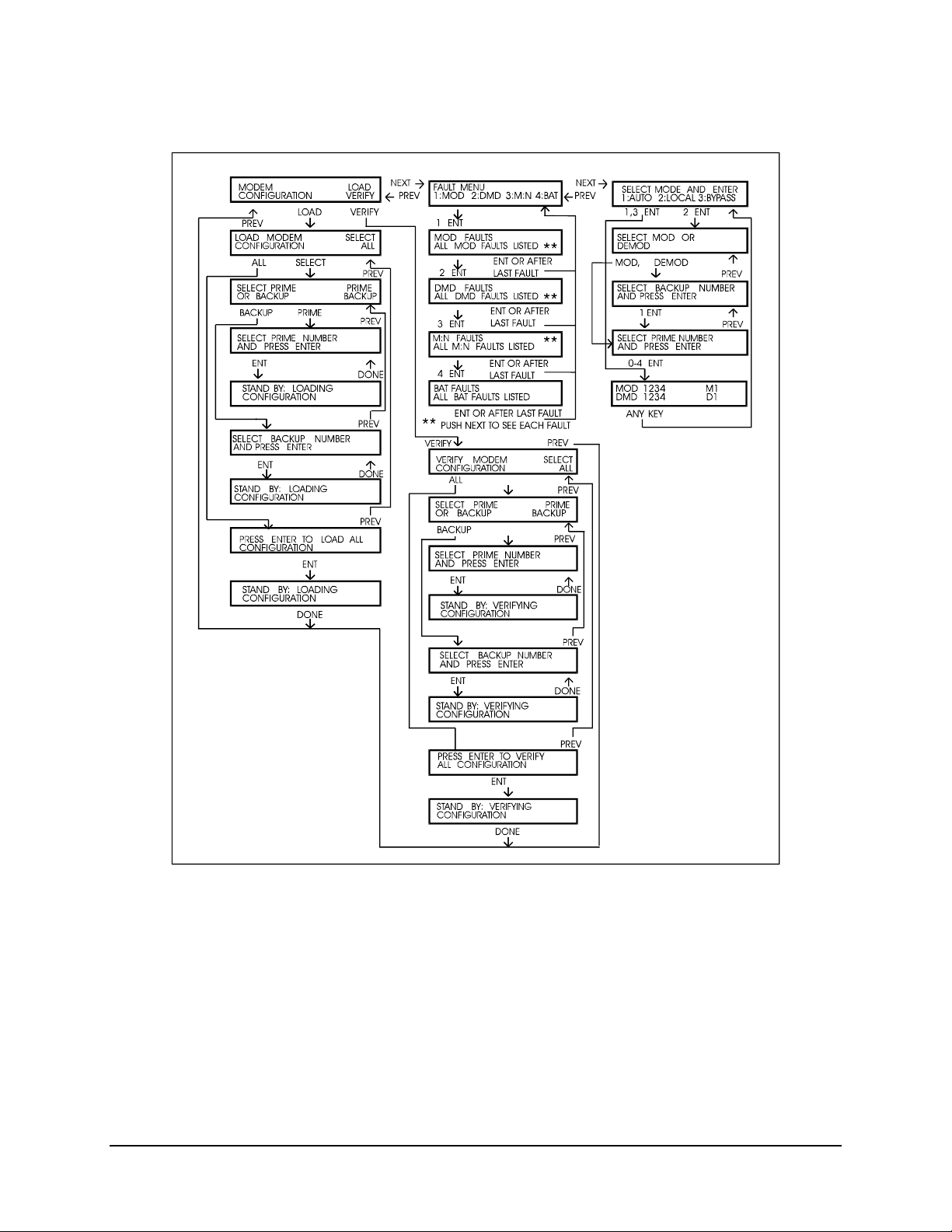
B.14 Load Modem Configurations ................................................................................................................ B–10
B.15 Verify Modem Configuration(s)............................................................................................................. B–10
B.16 Operational Status Commands (Faults)...............................................................................................B–11
GLOSSARY ............................................................................................................. g–1
INDEX ........................................................................................................................ i–1
vii
Page 10

SMS-458B Modem Protection Switch Revision 2
Preface MN/SMS458B.IOM
Figures
Figure 1-1. SMS-458B.....................................................................................................................................1–1
Figure 1-2. System Block Diagram .................................................................................................................1–3
Figure 1-3. SMS-458B Upper-front Section Interior.......................................................................................1–5
Figure 1-4. SMS-458B IF Switching Matrix...................................................................................................1–5
Figure 1-5. Lower Section Interconnect Diagram ...........................................................................................1–6
Figure 1-6. SMS-458B Block Diagram...........................................................................................................1–7
Figure 2-1. Typical Switch Rack Installation ..................................................................................................2–3
Figure 2-2. SMS-458B Rear Panel View.........................................................................................................2–5
Figure 3-1. SMS-458B Front Panel View .......................................................................................................3–2
Figure 3-2. Display Map..................................................................................................................................3–5
Figure 3-3. SMS-458B Switching Algorithm Flow Chart Demodulator/Modem .........................................3–20
Figure 3-4. SMS-458B Switching Algorithm Flow Chart Modulator...........................................................3–21
Figure 4-1. Monitor and Control .....................................................................................................................4–2
Figure 4-2. Prime IDR/G.703 Interface Switch.............................................................................................4–14
Figure 4-3. Backup IDR/G.703 Interface Switch ..........................................................................................4–14
Figure 4-4. Address Decoder/Driver..............................................................................................................4–15
Figure 4-5. Address Decoder/Driver .............................................................................................................4–16
Figure 4-6. Switch Driver..............................................................................................................................4–18
Figure 4-7. IF Switch Driver Block Diagram................................................................................................4–18
Figure 4-8. Data Switch Controller Card.......................................................................................................4–19
Figure 4-9. IF Switch.....................................................................................................................................4–21
Figure 4-10. Online Telemetry ......................................................................................................................4–22
Figure 4-11. Online Telemetry Block Diagram.............................................................................................4–23
Figure A-1. SMS-458B for SDM-2020 Modulator (TX only) with ECL/HSSI Data Interface ....................A–4
Figure A-2. SMS-458B for SDM-2020 Modulator (TX only) with ECL/HSSI Data Interface.....................A–5
Figure A-3. SMS-458B for SDM-2020 Modulator (TX only) with G.703 Data Interface.............................A–7
Figure A-4. SMS-458B for SDM-2020 Modulator (TX only) with G.703 Data Interface.............................A–8
Figure A-5. SMS-458B for SDM-9000 Satellite Modem with 50-Pin Data Interface .................................A–10
Figure A-6. SMS-458B for SDM-9000 Satellite Modem with 50-Pin Data Interface .................................A–11
Tables
Table 1-1. SMS-458B Specification................................................................................................................1–9
Table 2-1. Rear Panel Connections..................................................................................................................2–4
Table 4-1. Relay-Remote Command Words....................................................................................................4–7
Table 4-2. Modem Target Words ....................................................................................................................4–7
Table 4-3. Relay-Remote Command Functions...............................................................................................4–8
Table 4-4. Relay-Remote Command Examples...............................................................................................4–9
Table A-1. Equipment List .............................................................................................................................A–2
Table A-2. Cable Assembly............................................................................................................................A–3
Table A-3. Cable Connection .........................................................................................................................A–3
Table A-4. Cable Assembly............................................................................................................................A–6
Table A-5. Cable Connection .........................................................................................................................A–6
Table A-6. Cable Assembly............................................................................................................................A–9
Table A-7. Cable Connection .........................................................................................................................A–9
viii
Page 11
SMS-458B Modem Protection Switch Revision 2
Preface MN/SMS458B.IOM
About this Manual
This manual provides installation and operation information for the Comtech EF Data
SMS-458B Modem Protection Switch. This a technical document intended for earth
station engineers, technicians, and operators responsible for the operation and
maintenance of the SMS-458B..
Related Documents
The following documents are referenced in this manual:
• Department of Defense (DOD) MIL-188-114A, “Electrical Characteristics of
Digital Interface Circuits”
• Comtech EF Data, SDM2020 Modulator, Rev. 4 dated, September 15, 1999
Installation and Operation Manual
• Comtech EF Data, SDM-9000, Rev. 4, dated, May 5, 1997 Installation and
Operation Manual
Conventions and References
Cautions and Warnings
CAUTION indicates a hazardous situation that, if not avoided, may result in
minor or moderate injury. CAUTION may also be used to indicate other
CAUTION
unsafe practices or risks of property damage.
WARNING indicates a potentially hazardous situation that, if not avoided,
could result in death or serious injury.
WARNING
IMPORTANT indicates a statement that is associated with the task
IMPORTANT
being performed.
ix
Page 12

SMS-458B Modem Protection Switch Revision 2
Preface MN/SMS458B.IOM
Metric Conversion
Metric conversion information is located on the inside back cover of this manual. This
information is provided to assist the operator in cross-referencing English to Metric
conversions.
Recommended Standard Designations
Recommended Standard (RS) Designations have been superseded by the new designation
of the Electronic Industries Association (EIA). References to the old designations are
shown only when depicting actual text displayed on the screen of the unit (RS-232, RS485, etc.). All other references in the manual will be shown with the EIA designations
(EIA-232, EIA-485, etc.) only.
Trademarks
Other product names mentioned in this manual may be trademarks or registered
trademarks of their respective companies and are hereby acknowledged.
Reporting Comments or Suggestions Concerning this Manual
Comments and suggestions regarding the content and design of this manual will be
appreciated. To submit comments, please contact the Comtech EF Data Customer
Support Department.
Overview of Changes Made to Revision 1
x
Page 13

SMS-458B Modem Protection Switch Revision 2
Preface MN/SMS458B.IOM
ELECTRICAL SAFETY
The SMS-458B Modem Protecrtion Switch has been shown to comply with the following safety
standard:
• EN 60950: Safety of Information Technology Equipment, including electrical business
machines.
The equipment is rated for operation over the range 90 to 264 volts AC. It has a maximum
power consumption of 160 watts.
FUSES
The SMS-458B Modem Protecrtion Switch is fitted with two fuses, one each for line and neutral
connections. These are contained within the body of the IEC power connector, behind a small
plastic flap.
• For 230 volt AC operation, use T0.75A, 20mm fuses.
• For 115 volt AC operation, use T1.25A fuses, 20mm fuses.
IMPORTANT
Environmental
The SMS-458B Modem Protecrtion Switch must not be operated in an environment
where the unit is exposed to extremes of temperature outside the ambient range 0 to 50°C
(32 to 122°F), precipitation, condensation, or humid atmospheres above 95% RH,
altitudes (un-pressurized) greater than 2000 meters, excessive dust or vibration,
flammable gases, corrosive or explosive atmospheres.
Operation in vehicles or other transportable installations that are equipped to provide a
stable environment is permitted. If such vehicles do not provide a stable environment,
safety of the equipment to EN60950 may not be guaranteed.
For continued operator safety, always replace the fuses with the
correct type and rating.
xi
Page 14
SMS-458B Modem Protection Switch Revision 2
Preface MN/SMS458B.IOM
Installation
The installation and connection to the line supply must be made in compliance to local or
national wiring codes and regulations.
The SMS-458B Modem Protecrtion Switch is designed for connection to a power system
that has separate ground, line and neutral conductors. The equipment is not designed for
connection to power system that has no direct connection to ground.
The SMS-458B Modem Protecrtion Switch is shipped with a line inlet cable suitable for
use in the country of operation. If it is necessary to replace this cable, ensure the
replacement has an equivalent specification. Examples of acceptable ratings for the cable
include HAR, BASEC and HOXXX-X. Examples of acceptable connector ratings include
VDE, NF-USE, UL, CSA, OVE, CEBEC, NEMKO, DEMKO, BS1636A, BSI, SETI,
IMQ, KEMA-KEUR and SEV.
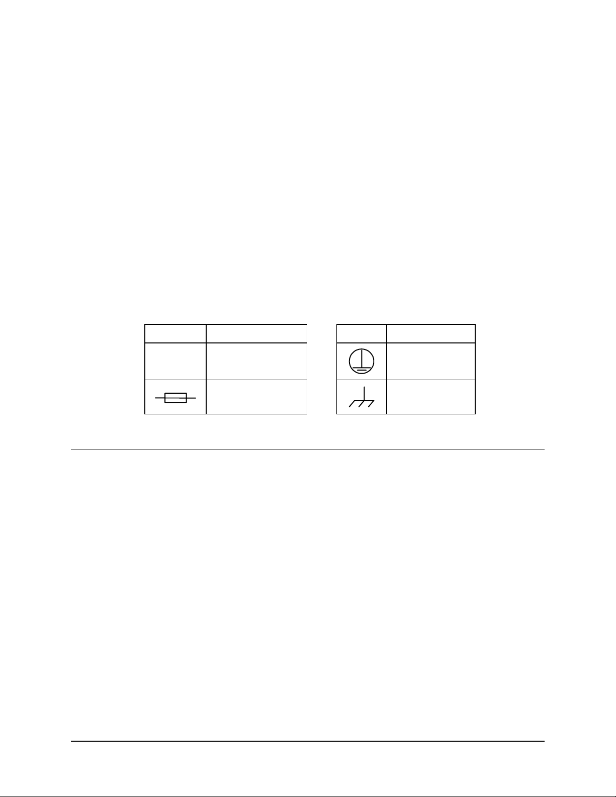
International Symbols:
Symbol Definition Symbol Definition
~
Alternating Current
Fuse
Telecommunications Terminal Equipment Directive
In accordance with the Telecommunications Terminal Equipment Directive 91/263/EEC,
this equipment should not be directly connected to the Public Telecommunications
Network.
Protective Earth
Chassis Ground
xii
Page 15

SMS-458B Modem Protection Switch Revision 2
Preface MN/SMS458B.IOM
EMC (Electromagnetic Compatibility)
In accordance with European Directive 89/336/EEC, the SMS-458B Modem Protecrtion
Switch has been shown, by independent testing, to comply with the following standards:
Emissions: EN 55022 Class B - Limits and methods of measurement of radio
interference characteristics of Information Technology Equipment.
(Also tested to FCC Part 15 Class B)
Immunity: EN 50082 Part 1 - Generic immunity standard, Part 1: Domestic,
commercial and light industrial environment.
Additionally, the SDM-2020D has been shown to comply with the following standards:
EN 61000-3-2 Harmonic Currents Emission
EN 61000-3-3 Voltage Fluctuations and Flicker
EN 61000-4-2 ESD Immunity
EN 61000-4-4 EFT Burst Immunity
EN 61000-4-5 Surge Immunity
EN 61000-4-6 RF Conducted Immunity
EN 61000-4-8 Power frequency Magnetic Field Immunity
EN 61000-4-9 Pulse Magnetic Field Immunity
EN 61000-4-11 Voltage Dips, Interruptions, and Variations Immunity
EN 61000-4-13 Immunity to Harmonics
In order that the Modem continues to comply with these standards,
observe the following instructions:
IMPORTANT
• Connections to the transmit and receive IF ports (Type N and Type F, female,
connectors) should be made using a good quality coaxial cable - for example
RG58/U (50Ω) or RG59/U (75Ω).
• All 'D' type connectors attached to the rear panel must have back-shells that
provide continuous metallic shielding. Cable with a continuous outer shield
(either foil or braid, or both) must be used, and the shield must be bonded to the
back shell.
• The equipment must be operated with its cover on at all times. If it becomes
necessary to remove the cover, the user should ensure that the cover is correctly
re-fitted before normal operation commences.
xiii
Page 16

SMS-458B Modem Protection Switch Revision 2
Preface MN/SMS458B.IOM
Warranty Policy
This Comtech EF Data product is warranted against defects in material and workmanship
for a period of one year from the date of shipment. During the warranty period, Comtech
EF Data will, at its option, repair or replace products that prove to be defective.
For equipment under warranty, the customer is responsible for freight to Comtech EF
Data and all related custom, taxes, tariffs, insurance, etc. Comtech EF Data is responsible
for the freight charges only for return of the equipment from the factory to the customer.
Comtech EF Data will return the equipment by the same method (i.e., Air, Express,
Surface) as the equipment was sent to Comtech EF Data.
Limitations of Warranty
The foregoing warranty shall not apply to defects resulting from improper installation or
maintenance, abuse, unauthorized modification, or operation outside of environmental
specifications for the product, or, for damages that occur due to improper repackaging of
equipment for return to Comtech EF Data.
No other warranty is expressed or implied. Comtech EF Data specifically disclaims the
implied warranties of merchantability and fitness for particular purpose.
Exclusive Remedies
The remedies provided herein are the buyer's sole and exclusive remedies. Comtech EF
Data shall not be liable for any direct, indirect, special, incidental, or consequential
damages, whether based on contract, tort, or any other legal theory.
Disclaimer
Comtech EF Data has reviewed this manual thoroughly in order that it will be an easy-touse guide to your equipment. All statements, technical information, and recommendations
in this manual and in any guides or related documents are believed reliable, but the
accuracy and completeness thereof are not guaranteed or warranted, and they are not
intended to be, nor should they be understood to be, representations or warranties
concerning the products described. Further, Comtech EF Data reserves the right to make
changes in the specifications of the products described in this manual at any time without
notice and without obligation to notify any person of such changes.
If you have any questions regarding your equipment or the information in this manual,
please contact the Comtech EF Data Customer Support Department.
xiv
Page 17
Chapter 1. INTRODUCTION
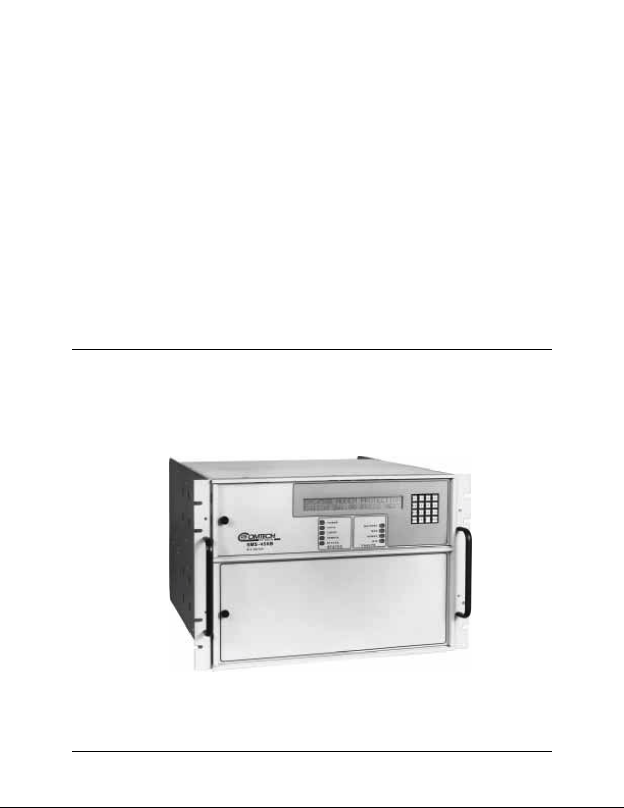
This chapter describes the SMS-458B Modem Protection Switch (Figure 1-1), referred to
in this manual as “the switch,”.
1.1 Overview
The SMS-458B Modem Protection Switch is a rack-mounted unit that provides
independent backup control for modulators and demodulators, or simultaneous modulator
and demodulator (modem) switching. The switch limits the loss of communication if a
primary modem element failure occurs.
Figure 1-1. SMS-458B
1–1
Page 18

SMS-458B Modem Protection Switch Revision 2
Introduction MN/SMS458B.IOM
1.2 Purpose and Function
The switch is a fully-automated, self-contained, switching unit for the following
equipment:
• SDM-2020 (Modulator) Satellite Modem
• SDM-2020 (Demodulator) Satellite Modem
• SDM-9000 Satellite Modem
The switch is designed to interface with ASI, G.703, or compatible data streams.
One backup modem provides redundancy for up to four prime modems. The switch will
automatically or manually switch one backup modem to take the place of any of four
prime modems.
In normal operation, each prime modem input is fed through to its corresponding IF
output, and the backup modems are fed to the offline IF outputs. When a modem fault is
detected, the faulted modem is switched offline and re-routed to one of the offline IF
outputs. The backup modem is configured identically to the failed modem and is
switched in its place, unless the backup modem is already backing up a prime of equal or
greater priority.
The switch does not contain an IF signal combining/dividing section, so that the user may
externally tailor the combiner/divider loss for a minimum configuration per application.
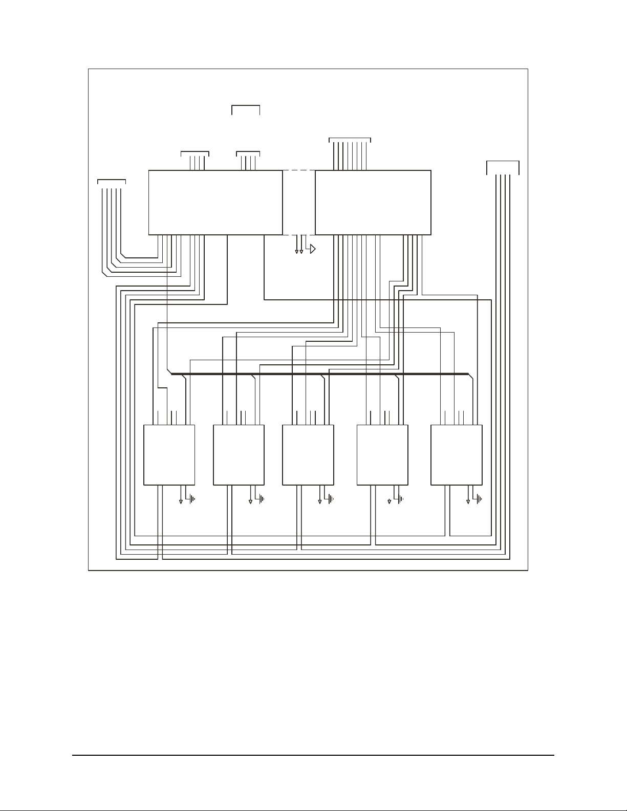
Figure 1-2 shows the switch interface between the prime and backup modems, the
terminal equipment, and IF converter equipment. The switch provides:
• All data and IF switching circuitry
• Complete status and fault reporting
1–2
Page 19
SMS-458B Modem Protection Switch Revision 2
Introduction MN/SMS458B.IOM
FROM
DOWNLINK
TO
UPLINK
AND
STATUS REPORTING
REMOTE CONTROL
INTF
RS-485 EXT INTF
RS-232 EXT INTF
MODEM CNTL
J1J2J3J4J5
J10
J11
J9
RX CLK
RX DATA
EQUIPMENT
J29
J30
J31
MOD PRIME 2
MOD PRIME 3
MOD OL STATUS
J12
TX DATA
MOD PRIME 4
DEMOD OL STATUS
REMOTE/FAULT
J6
J18 MOD PRIME 1 J28
J19
J20
J21
J13
J8
J7
SCT
FAULT
TX CLK
REMOTE
INPUTS
DEMOD
DOWNLINK
FOR BACKUP EQUIPMENT
J7
J8
J9
J10
DOWNLINK 1
DOWNLINK 2
DOWNLINK 3
DOWNLINK 4
MOD BACKUP
J26
J10
J9
RX CLK
RX DATA
DEMOD BACKUP
J11
J11
J12
J13
J7
J8
SCT
FAULT
TX CLK
TX DATA
REMOTE
ALL UNUSED
NOTE:
CONNECTIONS MUST BE
IF SECTION
SMS-458B
AC1
AC2
CGND TERMINATED INTO 75 OHMS.
AC1
AC2
GND
90-264 VAC
90-264 VAC
J10
J9
J12
J13
J11
RX CLK
TX CLK
TX DATA
RX DATA
EQUIPMENTTOTERMINAL
FROM
DOWNLINK
EQUIPMENT
A5,J2
A7,J1
A1,J2
A3,J1
A3,J2
123
123
A1,J4
A3,J3
A3,J4
A5,J1
A5,J3
RXTXRX
A5,J4
A7,J3
A7,J2
4
BK/UP
MODEM
4
A7,J4
A10,J1
A10,J2
J11
J12
J13
J9
J10
SCT
TX CLK
RX CLK
TX DATA
RX DATA
SMS-458B
DATA SECTION
DEMOD PRIME 1
DEMOD PRIME2DEMOD PRIME3DEMOD PRIME 4
A2,J6
A4,J6
A6,J6
A8,J6
A10,J3
J7
J8
FAULT
REMOTE
J9
RX DATA
J7
J8
J11
J10
J12
J13
SCT
FAULT
TX CLK
RX CLK
REMOTE
TX DATA
A1,J1
TERR
INTRFC
TXRXTXRXTX
PRIME
MODEMS
A1,J3
J7
J8
SCT
FAULT
REMOTE
PRIME 1
IF
AC1ACGRND
TX
RX IF
CP1
CP2
120 VAC
PRIME 2
TX IF
SDM-XXXX
GND
RX IF
AC
CP1
CP2
PRIME 3
AC1
GRND
GND
120 VAC
TX IF
RX IF
SDM-XXXX
AC1
AC
GND
CP1
CP2
120 VAC
PRIME 4
TX IF
RX IF
GRND
SDM-XXXX
AC1
AC
GND
CP1
CP2
120 VAC
BACKUP 1
TX IF
RX IF
AC1
GRND
SDM-XXXX
GRND
SDM-XXXX
AC
GND
CP1
CP2
120 VAC
Figure 1-2. System Block Diagram
1–3
Page 20

SMS-458B Modem Protection Switch Revision 2
Introduction MN/SMS458B.IOM
1.3 Description
The switch is complete and self-contained in a standard 19-inch (48 cm) rack-mounted
enclosure weighing approximately 50 lbs (22.68 kg). Modular construction methods were
used for ease in replacing modules.
The chassis assembly is segmented with upper and lower chassis-mounted backplanes.
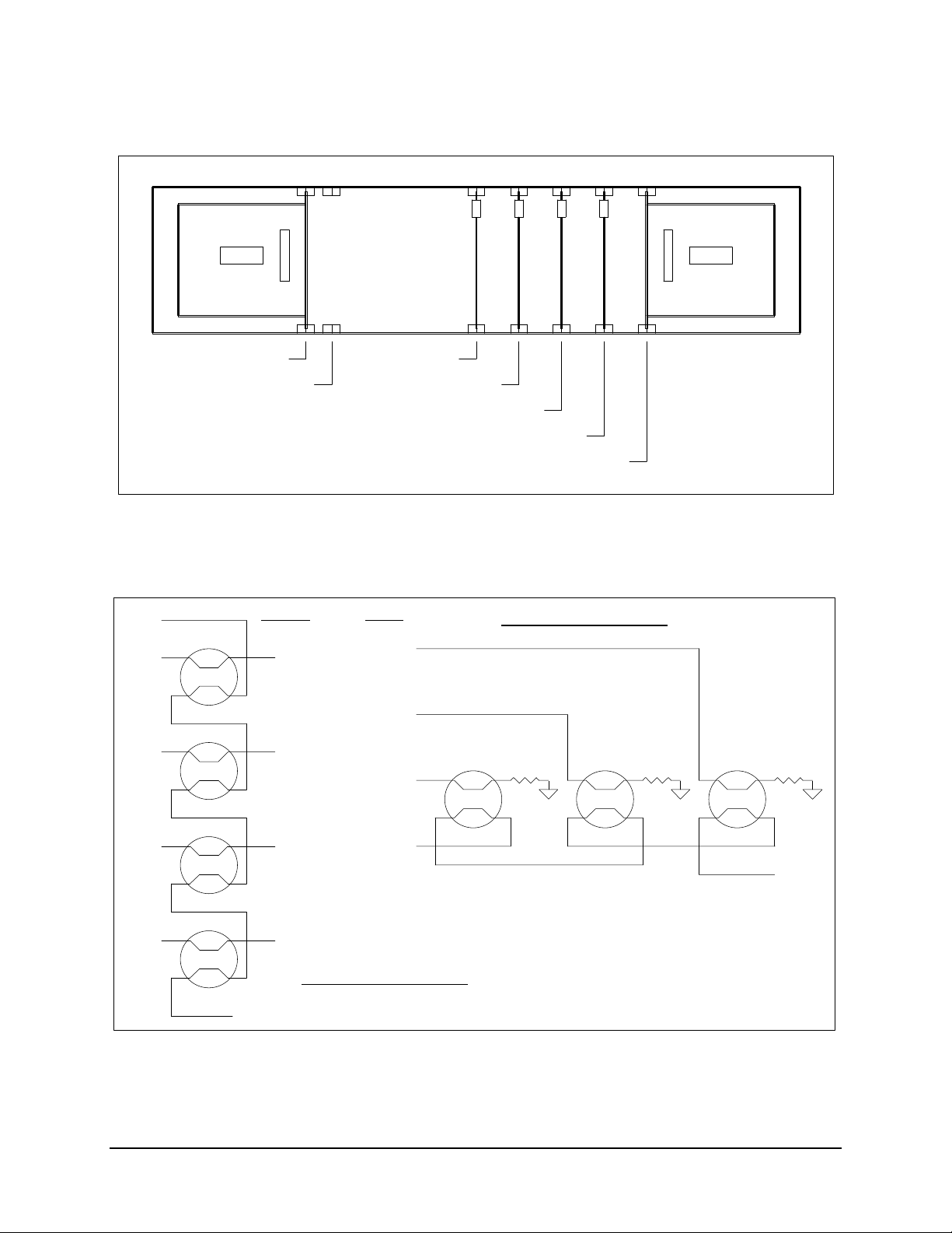
The top section (Figure 1-3) contains:
• Two power supplies and four printed circuit board (PCB) assemblies, providing:
! Front panel keypad and display accessible from the front panel.
! Serial remote interfaces, relay-remote/fault, status, and IF connections
accessible from the rear panel. Refer to Figure 1-4 for a block diagram of the
IF switching matrix.
The lower section (Figure 1-5) contains:
• High-speed data switching matrix and matrix driver.
• Data switch interface modules accessible from the rear.
Refer to Figure 1-6 for the interconnect diagram of the lower section.
The switch contains a microcontroller system. This system controls all switching
functions and maintains communication with the modems. It also communicates with an
optional external controller. A remote operator can control the switching by using a
terminal or computer and the remote serial interface.
Redundant power supplies maintain switch operation even if one power supply fails. The
switch and modem configurations are stored in battery-backed memory devices for
protection against power loss.
1–4
Page 21
SMS-458B Modem Protection Switch Revision 2
Introduction MN/SMS458B.IOM
BU MOD 1
MOD 1
MOD 2
SLOT 1
POWER SUPPLY
SLOT 3
SWITCH DRIVER
SLOT 2
SLOT 4
ADDRESS DEC/DRVNOT USED
MONITOR AND CONTROL
SLOT 5
ONLINE TELEMETRY
SLOT 6
POWER SUPPLY 2
SLOT 7
Figure 1-3. SMS-458B Upper-Front Section Interior
IF 1
IF 2
INPUTSOUTPUTS
DOWNLINK 4
DOWNLINK 3
DOWNLINK 2
DEMODULATOR SWITCH
MOD 3
MOD 4
IF 3
IF 4
DOWNLINK 1
BACKUP DEMOD 1
DEMODULATOR SWITCH
BACK-UP 1 IF OUTPUT
Figure 1-4. SMS-458B IF Switching Matrix
1–5
Page 22

SMS-458B Modem Protection Switch Revision 2
Introduction MN/SMS458B.IOM
TX DATA
J1
RX DATA
J2
J3
BACKUP
MODEM
J27
J18
J17
TERR
J28
J26
J25
J5
J6
PRIME 4
TX
TERR
RX
TX
MODEM
RX
PRIME 3
J1
J5
J2
J3
J6
J4
JP1
TX
TERR
RX
TX
MODEM
RX
JP2
J1
J2
J3
J4
PRIME 2
J5
J6
TX
TERR
RX
TX
MODEM
RX
J1
J2
J3
J4
J30 J31
J19
J20
J5
J6
J11
J12
PRIME 1
TX
TERR
RX
TX
MODEM
RX
J1
J2
J3
J4
J16
J15
AS/1314-1
RX DATA
SWITCH
J24
J23
JP3
DATA SWITCH
CONTROLLER
AS/2031
J2
J1
Figure 1-5. Lower Section Interconnect Diagram
J21
J22
AS/1314-1
TX DATA
SWITCH
J13
J14
J27J28
1–6
Page 23
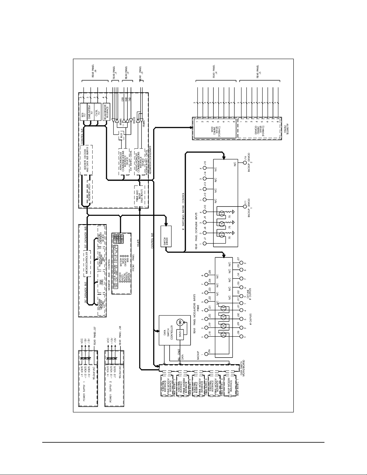
SMS-458B Modem Protection Switch Revision 2
Introduction MN/SMS458B.IOM
Figure 1-6. SMS-458B Block Diagram
1–7
Page 24

SMS-458B Modem Protection Switch Revision 2
Introduction MN/SMS458B.IOM
1.4 Major Assemblies
The switch consists of the following assemblies:
Assembly Description Part No. QTY
Chassis AS/2040-1
Controller Motherboard AS/1317
Data Switch Motherboard AS/2034
Data Switch Controller AS/2031 2 each
Monitor and Control AS/0356
Address Decoder/Driver AS/1048
IF Switch Driver AS/1316
IF Switch AS/1314
O/L Telemetry AS/0585
Display/Keypad AS/0540
Power Supply AS/1508-1 2 each
Prime Interface Switch AS/2068 up to 4
Backup Interface Switch AS/2069 1 each
1.5 System Requirements
With all interface switch modules installed, the switch is capable of operation as a 1:4
protection switch (i.e., one full-duplex standby modem can back up four full-duplex
primary modems).
The switch can be configured in any combination including:
• TX only modems
• RX only modems
• Multiple downlinks (limited to 4)
Refer to Section 3.1 for a complete explanation of the configuration function.
1–8
Page 25

SMS-458B Modem Protection Switch Revision 2
Introduction MN/SMS458B.IOM
1.6 Specification
The operating specifications for the switch are described in Table 1-1.
Table 1-1. SMS-458B Specification
Operation
Number of Online Modems Expandable from 1 to 4 with plug-in prime
interface switch modules (the modems can be of
different data rates as long as the backup modems
are compatible).
Number of Backup Modems 1 backup modem with a plug-in backup interface
switch module.
Data Interfaces ASI
ECL
G.703
Return Loss > 15 dB.
IF Frequency Response 50 to 180 MHz.
Downlinks Each demodulator is configurable for 1 of 4
downlink connections.
Prime Modulator to Output Loss
Backup Modulator to Prime Output Loss
Manual Delay Switch-Over Time Modulator: 0 to 127.0 sec., in 0.5 sec. steps
Auto Delay Switch-Over Time Modulator: < 1 sec
Switch-over Priority 1 of 3 priority levels independent for each
Remote Control Interfaces External control: EIA-485 or EIA-232
Batteries M&C: NiCad, 30-day memory retention.
Alarm Reporting Controller Fault Alarm: Form-C relay contact to
≤ 1 dB
≤ 1 dB
Demodulator: 0 to 127.0 sec., in 0.5 sec. steps
Demodulator: < 3 sweep periods of the back-up
demodulator.
modulator and demodulator (modulators and
demodulators may switch simultaneously in certain
applications).
Baud rates from 110 to 9600.
Parity: Even or Odd.
Addresses from 1 to 255.
48 hr. charge time.
indicate controller or power supply failure.
System Fault Alarm: Form-C relay contact to
indicate any non-catastrophic failure.
Demodulator Fault Alarm: Form-C relay contact to
indicate all demodulators faulted and a probable IF
loss.
1–9
Page 26

SMS-458B Modem Protection Switch Revision 2
Introduction MN/SMS458B.IOM
Table 1-1. SMS-458B Specification (Continued)
Indicators Front panel LEDs:
• Power supply on
• Auto mode
• Local mode
• Remote mode
• Bypass mode
• Battery fault
• Modulator system failure
• Demodulator system failure
• Controller and power supply fault
48 character display of:
• Prime modulator status
• Prime demodulator status
• Backup demodulator status
• Backup modulator status
• Active modulators (prime and backup)
• Active demodulators (prime and backup)
• Modem address
• Modem interface
• Modem downlink
• Modem priority
• Modem delay
• Modem configuration
• Fault menus
Operation Modes Auto
Local
Remote
Bypass
Controls Complete control of all M:N functions from the
front panel or through the remote interface.
General
Input Voltage 90 to 264 VAC (-48 Vdc optional).
Line Power 160 W max. with both power supplies operating.
Line Frequency 47 to 63 Hz
Size 19 W x 22D x 12.20H inches
(48.2 6W x 55.88 D x 31H cm)
Weight 50 lbs (22.68 kg)
1–10
Page 27

Chapter 2. INSTALLATION
This chapter provides the information reflecting unpacking, external connections, and
installation.
2.1 Unpacking
The switch and manual are packaged in preformed reusable foam inside a cardboard
carton.
To remove the switch, proceed as follows:
Do not use any cutting tool that will extend more than 1 inch into the
container and cause damage to the switch.
CAUTION
CAUTION
1. Cut the tape at the top of the carton and open the flaps.
The switch weights 50 lbs. (22.68 kg). Use caution when lifting the switch
out of the carton to avoid bodily injury.
2. Lift off the preformed foam packing and remove the manual and the unit.
3. Save the packing material for reshipment either back to the factory or to another
site.
4. Inspect the equipment for damage incurred during shipment.
5. Check the equipment against the packing list shipped with the equipment to
ensure that the shipment is complete.
2.2 Rack Installation
2–1
Page 28

SMS-458B Modem Protection Switch Revision 2
Installation MN/SMS458B.IOM
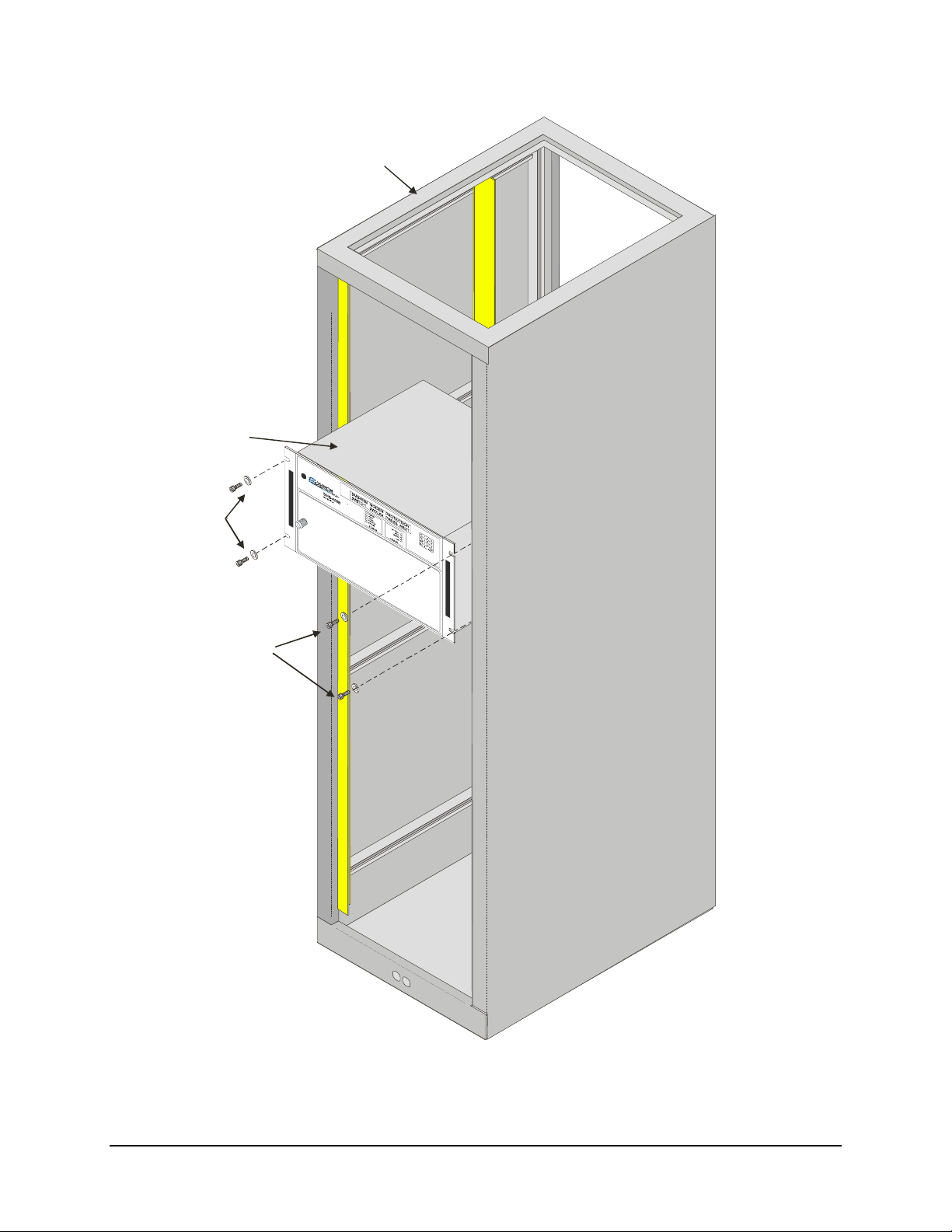
Install the switch in the rack (Figure 2-1) as follows:
1. Be sure that all interface switch modules are in their proper positions and are
fully seated in the rear backplane.
2. Mount the switch in the customer-selected position in the equipment rack. Secure
using eight mounting bolts and washers.
3. Turn front panel knob and open the front panel. Verify that the two power
supplies and four circuit modules are properly seated in the upper backplane.
4. Prior to turning on the power switches, read and become familiar with Chapter 3,
Front Panel Operation.
5. Turn on each power supply POWER switch located inside the front panel. The
power switch is on when the switch is depressed toward the “1” symbol or when
the red-side of the switch is exposed.
6. Close the front panel by securing the front panel knob. Configure the switch as
described in Chapter 3. Place the switch in the proper mode for operation.
7. Connect all appropriate connectors to the switch rear panel connectors as
specified in Appendix A.
8. If any problems occur during installation or operation, refer to Chapter 5 for
troubleshooting information.
2–2
Page 29
SMS-458B Modem Protection Switch Revision 2
Installation MN/SMS458B.IOM
EQUIPMENT RACK
SMS-458 SWITCH
MOUNTING
BOLTS AND
WASHERS
MOUNTING
BOLTS AND
WASHERS
Figure 2-1. Typical Switch Rack Installation
2–3
Page 30

SMS-458B Modem Protection Switch Revision 2
Installation MN/SMS458B.IOM
2.3 External Connections
All connections between the switch and other equipment are made through rear panel
connections. Table 2-1 lists these connectors, and Figure 2-2 shows their locations. The
uses of these connectors are described in the following sections.
Table 2-1. Rear Panel Connections
Name
DATA I/O MODULES J5, J6
REMOTE J1, J2, J3 9-pin D Remote Interface
ON-LINE STATUS J4, J5 25-pin D Online Status Reporting
RELAY/REMOTE FAULTS J6 25-pin D Relay/Remote and Faults
DOWNLINK INPUTS J7 to J10,
BACK-UP DEMODS J11, J16 BNC Downlink Outputs to Backup
PRIME MOD INPUTS J18 to J25 BNC Modulator IF Inputs
BACK-UP MOD INPUTS J26, J36 BNC Backup Mod IF Inputs
OFF-LINE IF OUTPUTS J17, J27 BNC Offline Mod IF Outputs
IF OUTPUTS J28 to J35 BNC IF Outputs to Uplinks
AC POWER J37, J38 CEE22 AC Power Input
GROUND J39 #10-32 stud Chassis Ground
Ref Desig
J1 – J4
J12 to J15
Connector
Type
50-pin D BNC
BNC
BNC Downlink IF Inputs
Function
Mod, Demod Faults
G.703, ECL/HSSI, I/O
Demods
Note: All unused BNC connectors must have a 75 Ω termination.
2–4
Page 31
SMS-458B Modem Protection Switch Revision 2
Installation MN/SMS458B.IOM
RS485
RS232
RS485
TX
DATA
RX
DATA
J2
TX
DATA
J3
RX
DATA
J4
EXTERNAL
CONTROL
90-264 VAC
A1
J1
J2
MODEM
J3
AS/2068
J37
A2 A3
TERR
DATAJ1
J5
PRIME
MODEM
J6
J7
J8
J9
J10
J11
TX
DATA
J1
RX
DATA
J2
TX
DATA
J3
RX
DATA
J4
1 1 N/C
22
DOWN
LINK
INPUTS
33
4 4 N/C
BACK-UP
1 2 N/C
DEMODS
AS/2068
J12
N/C
J13
N/C
J14
J15
J16
DATA
J5
PRIME
MODEM
J6
A4
PRIME INTERFACE
SWITCH MODULES
1
J17
OFF-LINE
IF OUTPUTS
N/C
J27
2
A5
TX
DATATERR
J1
RX
DATA
J2
TX
DATA
J3
RX
DATA
J4
123
J28 J29 J30
MOD
ON-LINE STATUS
J4
A6
TERR
DATA
J5
PRIME
MODEM
J6
AS/2068
321
TX
DATA
J1
RX
DATA
J2
TX
DATA
J3
RX
DATA
J4
J20J19J18
Figure 2-2. SMS-458B Rear Panel View
N/C
J22J21
J23
54
PRIME MOD INPUTS
IF OUTPUTS
45
J31 J32
DEMOD
ON-LINE STATUS REMOTE/FAULT
J5
A7 A8
TERR
DATA
J5
PRIME
MODEM
J6
AS/2068
N/C
67
N/C N/C N/C
J33 J34
J6 J38
N/CN/CN/C
J25
J24
8
76
BACK-UP
MOD INPUTS
8
J35
90-264 VAC
A9 A10
TX
DATA
J1
RX
DATA
J2
BACK-UP
MODEM
J3
AS/2069
BACKUP INTERFACE
SWITCH MODULE
1
J26
N/C
J36
2
2–5
Page 32

SMS-458B Modem Protection Switch Revision 2
Installation MN/SMS458B.IOM
2.3.1 Data I/O
Connect the Modem and Terrestrial Data I/O to the plug-in interface switch modules in
the lower-rear section of the switch. The interface switch module slots are designated A1
through A10 (left to right, viewed from the rear):
• A1 through A8 are slots for prime interface switch modules 1 through 4
(1 module for every 2 slots).
• A9 and A10 are the backup module slots (1 module for every 2 slots).
Prime interface switch modules have two sets of connectors:
• Connectors J1, J2, and J5 on the top connect to terrestrial equipment.
• J3, J4, and J6 on the bottom connect to the prime modem.
The backup interface switch module has three connectors designated J1, J2, and J3 for
backup modem connection.
Refer to Section 4.2 for electrical specifications and pinouts of the data connectors.
2–6
Page 33

SMS-458B Modem Protection Switch Revision 2
Installation MN/SMS458B.IOM
2.3.2 Remote Interface (J1, J2, J3)
The remote interface connectors provide serial remote interface to the switch.
For external control of the switch, an external controller can connect through J1
(EIA-485) or J2 (EIA-232).
The prime and backup modems connect to the switch through J3 (EIA-485), the modem
control interface connector. This connector provides a bus-type control interface,
required for system operation.
The remote interfaces connectors are 9-pin female D connectors, with screw locks for
mechanical security. The remote connector is a DCE interface.
EIA-485 EIA-232
Pin # Name Pin # Name
1 GND 1 N/C
2 N/C 2 RD (RX)
3 N/C 3 TD (TX)
4 +RX/TX 4 N/C
5 -RX/TX 5 GND
6 N/C 6 N/C
7 N/C 7 N/C
8 +RX/TX 8 N/C
9 -RX/TX 9 N/C
2.3.3 Online Status (J4, J5)
Connectors J4 and J5 provide the output for the modulator and demodulator backup
online status in form-C format.
J4 is for the modulator online status and J5 the demodulator online status.
2–7
Page 34

SMS-458B Modem Protection Switch Revision 2
Installation MN/SMS458B.IOM
Two 25-pin female D connectors provide the online status interfaces. Screw locks
provide mechanical security for the mating connector.
J4 J5
Pin # Name Name
1 Mod 1 COM Demod 1 COM
2 Mod 1 NC Demod 1 NC
3 Mod 1 NO Demod 1 NO
4 Mod 2 COM Demod 2 COM
5 Mod 2 NC Demod 2 NC
6 Mod 2 NO Demod 2 NO
7 Mod 3 COM Demod 3 COM
8 Mod 3 NC Demod 3 NC
9 Mod 3 NO Demod 3 NO
10 Mod 4 COM Demod 4 COM
11 Mod 4 NC Demod 4 NC
12 Mod 4 NO Demod 4 NO
13 to 24 No Connection No Connection
25 GND GROUND
2.3.4 Relay-Remote/Fault (J6)
This multi-pin connector provides both input and output signals. The inputs are contact
closures or logic level remote control inputs. The outputs are form-C relay contact
closure alarms for controller fault, M:N fault, and demodulator system fault.
The relay-remote input and fault status interface connects through a 25-pin female D
connector. Screw locks provide mechanical security for the mating connector.
Pin # Name
1 Controller Fault COM
2 Controller Fault NC
3 Controller Fault NO
4 Relay-Remote Input 0
5 Relay-Remote Input 1
6 Relay-Remote Input 2
7 Relay-Remote Input 3
8 Demodulator Fault COM
9 Demodulator Fault NC
10 Demodulator Fault NO
11 M:N Fault COM
12 M:N Fault NC
13 M:N Fault NO
14 to 24 No Connection
25 Ground
2–8
Page 35

SMS-458B Modem Protection Switch Revision 2
Installation MN/SMS458B.IOM
2.3.5 Downlink Inputs (J7 to J10, J12 to J15)
These are the downlink-input connectors. These connections provide the inputs to the
downlink-switching matrix.
J7, J8, J9, and J10 Inputs to backup modem 1
Note: J12, J13, J14, and J15are not used with this switch.
Up to four downlinks can be connected to the switch. Downlink inputs that are not being
used must be terminated into 75 Ω.
2.3.6 Back-Up Demods (J11, J16)
J11 and J16 Outputs from the downlink switching matrix
J11 Backup demod 1 output. It connects to the backup modem RX IF input.
Note: J16 is not used in this switch
Any of the 4 downlinks can be directed to J11. The default setting is downlink 1. The
input frequency range is 50 to 180 MHz, with input impedance of 75Ω. Terminate any
back-up demod port into 75Ω when not being used.
2.3.7 Prime Mod Inputs (J18 to J25)
J18 through J25 Prime modulator IF input connections to the modulator IF switching matrix.
They connect to the prime modem IF outputs.
Note: J22 through J25 are not used with this switch.
The input frequency range is 50 to 180 MHz, with input impedance of 75 Ω.
Prime mod inputs that are not being used must be terminated into 75 Ω.
2.3.8 Back-Up Mod Inputs (J26, J36)
J26 and
J36
The input frequency range is 50 to 180 MHz, with input impedance of 75 Ω.
Back-up modulator IF input connectors. They connect to the back-up modem IF
outputs.
Note: J36 is not used in this switch.
2–9
Page 36

SMS-458B Modem Protection Switch Revision 2
Installation MN/SMS458B.IOM
2.3.9 Offline IF Outputs (J17, J27)
J17 and J27 Offline IF output connectors, used as monitor and test points.
Note: J27 is not used in this switch.
The outputs of the backup modulators are routed here when not in use.
When backups are online, the offline primes are routed here.
2.3.10 IF Outputs (J28 through J35)
J28 through J35 Modulator IF switching matrix output connections. They connect to the
external uplink power combiners.
Note: J32 through J35 are not used in this switch.
Notes: Observe the following parameters:
1. During normal operation, the prime modulator IF outputs are switched at this
location.
2. During a fault condition, the backup modulators IF output will be switched at this
location.
3. The frequency range is 50 to 180 MHz, with output impedance of 75Ω.
4. The typical output power level is equal to the modem TX output level, which is
from -5 dBm to -20 dBm.
5. Any IF outputs that are not being used must be terminated into 75Ω.
2.3.11 AC Power (J37 and J38)
Applying incorrect input voltage to these connectors can cause severe
damage to the switch and will void the product warranty. Verify that
CAUTION
the source voltage is correct before connecting the switch.
J37 and J38 Two independent, nonlocking, 3-prong power cords connect AC power to the two
power supplies.
Normal input voltage is 90 to 264 VAC, at 47 to 63 Hz (-48 ± 4.8 Vdc are optional).
Maximum power consumption is 80 W for each power supply.
2.3.12 Ground
A #10-32 stud is available on the rear panel for connecting the chassis to ground.
2–10
Page 37

Chapter 3. FRONT PANEL
This chapter describes the front panel operation of the switch.
3.1 Overview
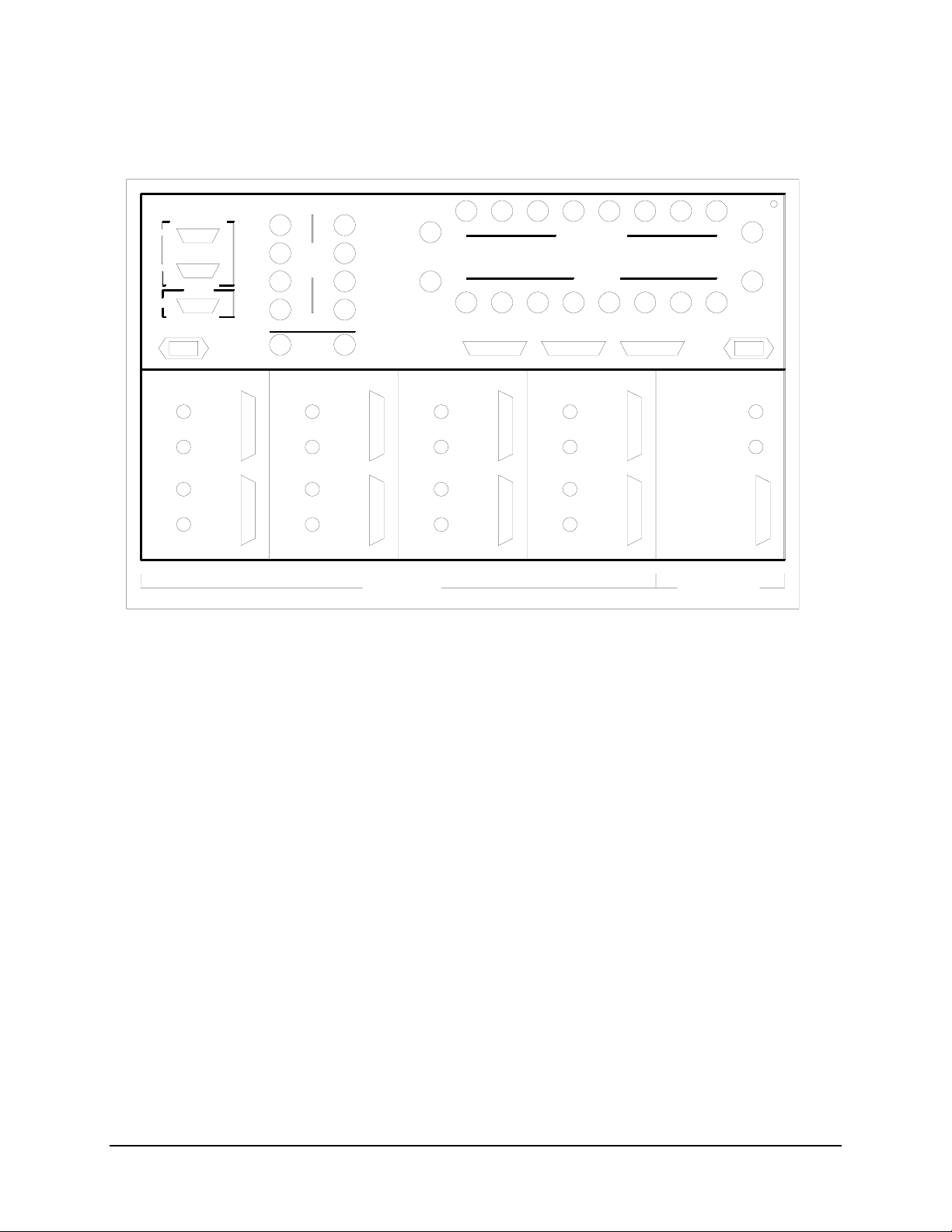
The switch front panel (Figure 3-1) provides the local interface to configure, operate, and
monitor the switch. Proper operation of the switch depends on its proper configuration
and setup. The following sections describe the front panel and its operation in detail.
A 48-character, 2-line LCD display in the upper-front panel displays options, and status
for the user.
The nine LEDs grouped under the LCD display provide mode and fault status at a glance,
and a 16-key keypad to the right allows the user to perform setup, configuration, and
operation functions.
OPERATION
3–1
Page 38

SMS-458B Modem Protection Switch Revision 2
Operation MN/SMS458B.IOM
Figure 3-1. SMS-458B Front Panel View
All switch functions are accessible to the user from the front panel through the function
keys, [F1] or [F2], the [PREV] key, and the [NEXT] key.
3.2 LED Indicators
Nine LEDs on the front panel indicate the general switch status and summary fault
information, as follows:
Faults
M:N (Red LED) Lights if M:N fault condition occurs.
MOD (Red LED) Lights if a modulator operation fault occurs.
DEMOD (Red LED) Lights if demodulator operation fault occurs.
BATTERY (Red LED) Lights if one of the battery voltages is low.
STATUS
POWER ON (Green LED) Lights when power is applied to the switch.
AUTO (Green LED) Lights when the switch is in the automatic operating mode.
LOCAL (Green LED) Lights when the switch is in the local operating mode.
REMOTE (Green LED) Lights when the switch is in the remote operating mode.
BYPASS (Green LED) Lights when the switch is in the bypass-operating mode.
3–2
Page 39

SMS-458B Modem Protection Switch Revision 2
Operation MN/SMS458B.IOM
3.3 Keypad and LCD Display
The keypad and LCD display provide an interface for the local user to access the menus
that configure and operate the switch. The keypad includes:
• Numbers 0 through 9
• Decimal
• [ENT]
• [F1] and [F2]
• [NEXT]
• [PREV]
The last four keys specified control the hierarchical menu structure. Menus provide for
local setup, configuration, and operation. Each menu contains a portion of the switch
control or setup algorithm. Only a limited knowledge of the switch is required, as the
menus are self-prompting and all options are displayed.
The base levels of this tree-structured front panel menu are as follows:
• ID menu displayed at power-on
• SYSTEM and MODEM SETUP menu
• MODEM CONFIGURATION menu
• FAULT menu
• MODE menu
• STATUS display
3–3
Page 40

SMS-458B Modem Protection Switch Revision 2
Operation MN/SMS458B.IOM
The ID menu displays the version of firmware implemented in the switch.
The [NEXT], [PREV], [F1], [F2], and [ENT] keys control the menus and allow menu
selections.
Some display messages have menu options on the right side aligned with the [F1] and
[F2] keys. Pressing either of these keys directs the display to the selected menu.
The user can also move forward or backward through the selected menu by pressing the
[NEXT] or [PREV] keys.
The switch beeps in response to keypad inputs:
• One beep acknowledges a valid entry with the appropriate action being taken.
• Two beeps indicate that the entry was invalid and no action was taken.
Once the correct menu is selected, the user can press the [ENT] key to enter, change, or
view the functions within that menu.
The STATUS display follows the MODE menu. It includes the following:
• Identifies the active modulator and demodulator, both prime and backup.
• Shows backup online status.
• Shows the fault status of both prime and backup modulators and demodulators.
The STATUS menu displays only the active modulators and demodulators. If any
modulator or demodulator is faulted, an “F” alternates with the modem number on the
display. The display shows online backup modulators and demodulators, with an arrow
pointing to the number of the prime being backed-up.
“Hot Standby” mode is identified by a dash between the backup modulator/demodulator
and the prime modulator/demodulator.
An asterisk is displayed while the backup modulator/demodulator is in process of backing
up a prime modulator/demodulator.
In all modes except BYPASS, the switch returns to the STATUS display returns after
approximately three minutes.
Refer to Figure 3-2 for a detailed description of the front panel menu. This figure
describes the independent mod/demod switch with support for use with an external
buffer/channel unit.
3–4
Page 41

SMS-458B Modem Protection Switch Revision 2
Operation MN/SMS458B.IOM
Figure 3-2. Display Map
3–5
Page 42
SMS-458B Modem Protection Switch Revision 2
Operation MN/SMS458B.IOM
Figure 3-2. Display Map (Continued)
3–6
Page 43

SMS-458B Modem Protection Switch Revision 2
Operation MN/SMS458B.IOM
3.4 System and Modem Setup
3.4.1 Prime Uplink and Downlink Ports
J28 through J35 Eight IF outputs available to connect to customer-supplied uplink power
combiners.
Note: Only J28 through J31 are used for this switch.
J7, J8, J9, J10 J7 through J10 are used when four downlink transponders are specified in the
system.
The following steps describe the uplink and downlink connections:
1. Connect the IF output cables 1 to 4 to the appropriate customer-furnished uplink
signal combiner inputs.
2. Connect the Downlink input cables 1 to 4 to the appropriate customer-furnished
downlink splitters.
Note: Be sure to terminate all unused IF outputs and downlink inputs with one of the
supplied 75Ω BNC terminations.
3.4.2 System Setup
Enter the SYSTEM SETUP menu to enter, change, or view the system setup
configuration. The definitions of the system setup functions are as follows:
Function Description
TIME AND DATE Time and date are entered and displayed.
DOWNLINK OPTIONS Prime and backup downlinks are selected and
displayed.
PRIME MODS Active prime modulators are selected and displayed.
PRIME DEMODS Active prime demodulators are selected and displayed.
BACKUP MODS Active backup modulators are selected and displayed.
BACKUP DEMODS Active backup demodulators are selected and
displayed.
MODEM ADDRESSES Prime and backup modem addresses are selected and
displayed.
*PRIME C/U Active prime channel unit addresses are selected and
displayed.
*BACKUP C/U Active backup channel unit addresses are selected and
displayed.
* Note: These functions are applicable only for Version 2.02.
3–7
Page 44

SMS-458B Modem Protection Switch Revision 2
Operation MN/SMS458B.IOM
In the SYSTEM SETUP menu, view system configuration parameters by using the
[NEXT] and [PREV] keys. The user also can enter data or change a parameter through
keypad entries.
• When all data or changes for that parameter are entered correctly,
press [ENT] to load the information into memory.
• If an incorrect entry is made, press [PREV] to return to that menu and re-enter
the data.
3.4.2.1 Time and Date Menu
This menu displays the current time and date. Enter and reset time and/or date as follows:
Time Press: F1
Type: HH MM (Use this format)
Press: ENT (Seconds reset to “0” and the new time loads into the clock
device)
Date Press: F2
Type: MM DD YY (Use this format)
Press: ENT (Loads the new date into the clock device)
3.4.2.2 Active Downlink Option Menu
Note: This switch uses only the 4-downlink/2 backup option. There are only four prime
modems and backup 2 is ignored.
This menu displays the current downlink and backup options that are active in the
system.
1. Press one of the [1] through [9] keys toggles the active status between:
• 4 downlinks — 2 backups
• 7 downlinks — 1 backup
2. Press [ENT] to load information into memory.
3.4.2.3 Active Prime Modulators Menu
3–8
Page 45

SMS-458B Modem Protection Switch Revision 2
Operation MN/SMS458B.IOM
This menu displays the current prime modulators that are active in the system.
1. Press one of the [1] through [4] keys toggles the active status (ON/OFF)
of the corresponding modulator only.
2. Press [ENT] to load information into memory.
3.4.2.4 Active Prime Demodulators Menu
This menu displays the current prime demodulators that are active in the system.
1. Press one of the [1] through [4] keys toggles the active status of the
corresponding demodulator only.
2. Press [ENT] to load information into memory.
3.4.2.5 Active Backup Modulators Menu
This menu displays the current backup modulators that are active in the system.
1. Press the [1] key to toggle the active status of the backup modulator only.
2. Press [ENT] to load information into memory.
3.4.2.6 Active Backup Demodulators Menu
Note: The switch does not support the use of a second backup modem. When selecting
the active backup for mod, demod, and downlink, the active backup can only be number
1. Selecting backup number 2 to be active will have no effect on the system, except
causing backup faults to occur.
This menu displays the current backup demodulators that are active in the system.
1. Press the [1] key to toggle the active status of the backup demodulator only.
2. Press [ENT] to load information into memory.
3.4.2.7 Modem Addresses Menu
This menu displays the current addresses of the prime and backup modems.
Addresses of 1 through 255 are valid.
1. Enter a new address and press [ENT] to load the address into memory.
2. If no address is entered for an active modem, an M:N fault results.
3–9
Page 46

SMS-458B Modem Protection Switch Revision 2
Operation MN/SMS458B.IOM
3.4.2.8 Prime Channel Unit Menu
This menu displays the current addresses of active prime channel units (Version 2.02 or
greater). Addresses of 1 through 255 are valid.
1. Enter a new address and press [ENT] to load the address into memory.
2. If no address is entered for an active channel unit, an M:N fault results.
3.4.2.9 Backup Channel Unit Menu
This menu displays the current addresses of active backup channel unit (Version 2.02 or
greater). Addresses of 1 through 255 are valid.
1. Enter a new address and press [ENT]to load the address into memory.
2. If no address is entered for an active channel unit, an M:N fault results.
Note: To avoid corrupting the configurations of the prime modems, do not use the global
address “0”.
3.4.3 Modem Setup
To enter, change, or view the modem setup configuration, enter the MODEM SETUP
menu. The MODEM SETUP functions are as follows:
Function Description
DOWNLINK Downlink assignment (1 through 4) is selected and displayed for
demodulators.
MOD PRIORITY The prime modulator priorities are selected and displayed
DEMOD PRIORITY The prime demodulator priorities are selected and displayed.
DEMOD DELAY The prime demodulator online delay is selected and displayed.
MOD DELAY The prime modulator online delay is selected and displayed.
SELECT C/U The presence of an external channel unit or buffer is selected and
displayed.
1. Press [F1] or [F2] to select prime or backup modems.
2. View the parameters by using the [NEXT] and [PREV] keys.
3. A flashing cursor will be displayed over the selected parameter.
To enter data or change a parameter, the keypad is used to enter the data. When all data
or changes for that parameter are correct, press the [ENT] key to load the information
into memory.
3–10
Page 47

SMS-458B Modem Protection Switch Revision 2
Operation MN/SMS458B.IOM
3.4.3.1 Downlink Selection Menu
Note: Hardware connections for uplink and downlink must be identical to the setup
selection. Any difference causes erroneous switch operation.
This menu displays the current downlink number (1 through 4) for each demodulator.
1. Enter the number of the downlink selected.
2. Press [ENT] (that information is loaded into memory).
3. If no downlink is selected for an active demodulator, an M:N fault results.
3.4.3.2 Demodulator Priorities Menus
These menus display the current priority level for all prime demodulators:
• “1” indicates high priority.
• “2” indicates medium priority.
• “3” indicates low priority.
1. Enter priority level and press [ENT] (the information is loaded into memory).
2. If nothing is entered, the priority will be 3 (low priority).
Note: The backup algorithm uses priority levels to make backup decisions. When a
backup demodulator is online for a faulted prime with a lower priority than a newly
faulted demodulator is, that backup modem becomes available for use to backup the
newly faulted unit having the higher priority.
3.4.3.3 Modulator Priorities Menus
These menus display the current priority level for all prime modulators.
• “1” indicates high priority.
• “2” indicates medium priority.
• “3” indicates low priority.
1. Enter priority level and press [ENT] (the information loads into memory).
2. If nothing is entered, the priority will be 3 (low priority).
Note: The backup algorithm uses priority levels to make backup decisions. When a
backup modem is online for a faulted prime with a lower priority than a newly faulted
modem, that backup modem becomes available for use to backup the newly faulted unit
having the higher priority.
3–11
Page 48

SMS-458B Modem Protection Switch Revision 2
Operation MN/SMS458B.IOM
3.4.3.4 Demodulator Delay
This menu displays the current demodulator online delay for each prime demodulator,
and allows the user to enter a new parameter. The DEMOD DELAY is the time allowed
for the prime demodulator to clear its faulted state. At the end of this delay, if the prime is
no longer faulted, it will be restored to online status. If the prime is still faulted, the
backup demodulator is committed to that channel and will be unavailable for any other
faulted prime having the same or lower priority. The user selects “1”, “2”, or “3”:
• “1” = no time delay
• “2” = manual
• “3” = automatic delay selection (2 times the sweep period)
1. Enter DEMOD DELAY # and press [ENT] (loads the information into memory).
2. Enter “2” and press [ENT] (enters a delay from 0 to 127.0 seconds, in 0.5 second
increments).
3. Press [ENT] (the delay data loads into memory).
4. If nothing is entered, the switch automatically defaults to “3” (automatic).
3.4.3.5 Modulator Delay
Note: In “modem switch” applications, the MOD/DEMOD DELAY and PRIORITY
settings are replaced by MODEM DELAY and PRIORITY settings.
The Modulator Delay menu displays the current modulator online delay for each prime
modulator, and allows the user to enter a new parameter. The MOD DELAY is the time
allowed for the prime modulator to clear its faulted state. At the end of this delay, if the
prime is no longer faulted, it is restored to online status. If the prime is still faulted, the
backup modulator is committed to that channel and will be unavailable for any other
faulted prime having the same or lower priority. The user selects “1” or “2”:
• “1” = no time delay
• “2” = manual
1. Enter MOD DELAY # and press [ENT] (loads the information into memory).
2. Enter “2” and press [ENT] (enters a MOD DELAY from 0 to 127.0 seconds, in
0.5 second increments).
3. Press [ENT], the delay data loads into memory.
4. If nothing is entered, the switch defaults to “1” (None).
3–12
Page 49

SMS-458B Modem Protection Switch Revision 2
Operation MN/SMS458B.IOM
3.4.3.6 Channel Unit Selection
Note: The default is Option 1, no channel unit.
This menu displays the current channel unit setting.
• Option 1 selects no channel unit
• Option 2 selects an external channel unit for the modem.
3.4.4 Modem Configuration
3.4.4.1 Prime and Backup Modem Configuration
The prime modems have all parameters properly configured for operation prior to
configuration loading or verifying. The only required parameters for a backup modem are
the data rate and code rate assignments in the modem’s utility menu.
To communicate with the modems, the switch must have the modem addresses entered
into the system configuration. The serial interface type, baud rate, and parity of the
switch modem control interface are fixed and therefore can not be programmed by the
user. For interface information, refer to Section 4.2.
The modems must be set to:
• EIA-485 interface
• 9600 BAUD
• Even parity
Each modem in the switch system must have its own unique address. The interface type,
baud rate, parity, and addresses are selected on the M&C card in the modem (see the
modem installation and operation manual).
3–13
Page 50

SMS-458B Modem Protection Switch Revision 2
Operation MN/SMS458B.IOM
3.4.4.2 Modem Configuration Menu
To load the modem configurations, press [F1] (LOAD) in the MODEM
CONFIGURATION menu and proceed using one of the following steps:
1. Press F1 (SELECT) menu to load the configuration of an individual prime or
backup modem.
a. Press [F1] (SELECT), the menu presents options of PRIME (F1) and
BACKUP (F2).
b. Select PRIME or BACKUP, the last menu will require entry of the prime
or backup modem number.
c. The switch automatically loads the configuration of the modem selected.
2. Press F2 (ALL) menu to load the configuration of all the active modems.
• Press [F2] (ALL), the menu requires that [ENT] be pressed to begin the
loading of all active modem configurations.
The switch displays “OK” or “ERROR” showing the result of the configuration loading
process. An “ERROR” response results in an M:N fault.
To verify the modem configurations, Press [F2] (VERIFY) in the MODEM
CONFIGURATION menu and proceed using one of the following steps:
1. Press [F1] (SELECT) menu to verify the configuration of an individual prime or
backup modem.
a. Press [F1] (SELECT), the menu presents options of PRIME (F1) and
BACKUP (F2).
b. Select PRIME or BACKUP, the last menu will require entry of the prime
or backup modem number.
c. The switch automatically verifies the configuration of the modem
selected.
2. Use the [F2] (ALL) menu to verify the configuration of all the active modems.
• Press [F2] (ALL), the menu requires that [ENT] be pressed to begin the
verifying of all active modem configurations.
The switch displays “OK” or “ERROR” showing the result of the configuration loading
process. An “ERROR” response results in an M:N fault.
Note: When any change is made in the prime or backup modem configuration, reload
that modem’s configuration in the switch. If this is not performed, a configuration verify
error will be flagged in the M:N fault menu.
3–14
Page 51

SMS-458B Modem Protection Switch Revision 2
Operation MN/SMS458B.IOM
3.4.5 Operation Modes
The MODE menu selects the mode of operation. At power-up, the switch defaults to the
BYPASS mode unless both of the following conditions exist:
• It was in a different mode prior to loss of power.
• Battery-backed memory was maintained.
The following modes of operation are available:
BYPASS All switching is halted. No change will take place until the switch is
returned to the AUTO, LOCAL, or REMOTE mode.
AUTOMATIC The Monitor and Control controls all switching.
LOCAL The on-site user controls all switching.
REMOTE In the REMOTE mode, a remote controller via the remote interface
controls all switching. The on-site user cannot select this mode of
operation.
3.4.5.1 Bypass Mode
The BYPASS mode is recommended for initial and subsequent configuration functions. It
is the default-operating mode at power-up if the switch was not programmed for a
different mode prior to loss of power or if the battery-backed memory was not
maintained. The switch is not capable of performing any switching functions in the
BYPASS mode. All configuration and communication functions continue to operate, but
no new backup operation can take place. Any backup operation performed prior to
selecting BYPASS will remain in effect.
To enter the BYPASS mode, proceed as follows:
• Press [3] and [ENT] while in the MODE menu.
3.4.5.2 Auto Mode
The AUTO mode is the normal operating mode for the switch. Refer to the flowcharts in
Figure 3-3 and Figure 3-4. If the switch was in this mode when power loss occurred, it
will return to this mode when power is restored (all previous backup status will be lost).
If there are faults present when power is restored, the switch will backup the highest
priority faulted modulator and/or demodulator accordingly. Because the switch is
communicating with the prime and backup modems in this mode, response to keypad
input and remote communication may be delayed.
To enter the AUTO mode, proceed as follows:
• Press [1] and [ENT] while in the MODE menu.
3–15
Page 52

SMS-458B Modem Protection Switch Revision 2
Operation MN/SMS458B.IOM
In the AUTO mode, the switch monitors the prime and backup modulator and
demodulator fault inputs, awaiting a failure.
• When no faults are present, the switch will place the backup modulator and
demodulator in the “Hot Standby” mode and a dash (–) will be displayed in the
status display. In this mode, the switch programs the backup modulator and
demodulator for the highest priority lowest numbered prime modulator and
demodulator, and connects the downlink IF to the backup demodulator. This
action prepares the backup modulator and demodulator for a minimal delay
backup of high-priority channels.
• When a fault does occur, the switch takes action according to the backup
algorithm. The backup algorithm selects the highest priority, lowest numbered
faulted channel for backup and will take a lower priority channel backup offline,
even if that channel is faulted, to back up a higher priority channel.
When a demodulator backup is required, the switch performs the following steps:
1. It verifies the configuration of the backup demodulator and reprograms it, if
necessary.
2. If more than one demodulator is faulted, the switch selects the demodulator with
the highest priority. If more than one faulted demodulator is set to the highest
priority, the switch selects from those the demodulator with the lowest channel
number.
3. The switch implements the sweep delay (not programmable by the user). This
delay is two times the sweep period of the demodulator. At the end of the sweep
delay or when the backup demodulator locks, the switch performs one of the
following operations:
a. If the backup demodulator fails to lock, the switch makes the backup
demodulator available for other faulted channels.
b. If the backup demodulator locks, the switch commits the backup
demodulator to the faulted prime and starts the demodulator delay timer. An
asterisk (*) will be displayed in the status display.
4. At the end of the demodulator delay, the switch again checks the fault status of
the prime demodulator.
a. If the prime demodulator is still faulted, the switch places the backup
demodulator online for the faulted prime, and an arrow (→) will be displayed
in the status display. The backup will then be available only to failed primes
having higher priority.
b. If the prime demodulator has locked during the demodulator delay, the
backup demodulator is made available for other faulted primes.
3–16
Page 53

SMS-458B Modem Protection Switch Revision 2
Operation MN/SMS458B.IOM
When a modulator backup is required, the switch performs the following steps:
1. It verifies the configuration of the backup modulator and reprograms it if
necessary.
2. If more than one modulator is faulted, the switch selects the modulator with the
highest priority. If more than one faulted modulator is set to the highest priority,
the switch selects the modulator with the lowest channel number.
3. It implements a 500-millisecond delay (not programmable by the user). At the
end of the delay, the switch performs one of the following operations:
a. If the prime modulator is not faulted, the switch makes the backup modulator
available for other faulted channels.
b. If the backup modulator is not faulted and the prime remains faulted, the
switch commits the backup modulator to the faulted prime and starts the
modulator delay timer. An asterisk (*) is displayed in the status display.
4. At the end of the modulator delay, the switch again checks the fault status of the
prime modulator.
a. If the prime modulator is still faulted, the switch places the backup modulator
online for the faulted prime, and an arrow (→) is displayed in the status
display. The backup is then available only to failed primes having higher
priority.
b. If the prime modulator clears its fault during the modulator delay, the prime
modulator is restored to service. The backup modulator is made available for
other faulted primes.
When a modem backup is required, the switch performs both demodulator and modulator
procedures simultaneously. However, the switch will not place the backup modem online
until the backup demodulator locks and the modem online delay timer times-out.
The switch continually verifies the configurations of all-active modulators and
demodulators. If the switch fails to verify any configuration, an M:N fault results.
Changing from any mode to another mode (including AUTO) does not change the
backup status unless a new fault occurs.
3.4.5.3 Local Mode
3–17
Page 54

SMS-458B Modem Protection Switch Revision 2
Operation MN/SMS458B.IOM
In this operating mode, the switch responds to keypad input affecting setup,
configuration, fault inquiries, and backup online status.
If the switch is in this mode when power loss occurs, it will return to this mode when
power is restored. However, the current backup status will be lost.
This mode also can be used for initial and subsequent configuration functions. (To enter
the LOCAL mode, press [2] and [ENT] while in the MODE menu.)
To change the backup status from local mode:
1. Press [F1] or [F2] to select modulator or demodulator. (If the switch is a modem
switch rather than an independent modulator/demodulator switch, press [ENT] to
continue.)
2. Select the backup modem number (1 or 2) and press [ENT].
3. Select the prime modem number from 0 to 4. (“0” takes the backup modulator or
demodulator offline; “1” to “4” selects that prime for backup.)
4. Press [ENT].
The switch performs the selected backup function and displays the online and fault status.
When the switch is in LOCAL mode, exercise care when changing the online status, as
the switch performs the selected function regardless of fault status or modulator and
demodulator compatibility.
3.4.5.4 Remote Mode
In this operating mode, the switch responds to serial remote interface or relay-remote
input. The switch can receive a full range of commands from the serial remote interface
user and a limited number from the relay-remote interface. If the switch was in this mode
prior to loss of power, it returns to this mode when power is restored. However, current
backup status will be lost. This mode can be entered only from the serial remote interface
or relay-remote interface.
For details of the remote interface specification, refer to Section 4.1.4 and Appendix A.
3.4.6 Faults
3–18
Page 55

SMS-458B Modem Protection Switch Revision 2
Operation MN/SMS458B.IOM
When any fault LED(s) is lighted, an operational fault condition exists. However, the
LEDs are only a summary visual alarm. The user uses the FAULT menu to determine the
exact cause of the fault and takes remedial action if necessary.
The FAULT menu provides fault information. Use the 1, 2, 3, 4, [NEXT], and [PREV]
keys to reveal the nature of any fault indicated by a front panel red LED.
The following sections list all the possible fault messages that could appear in each
category. Refer to Section 5.2 for a list of the possible causes and for the fault isolation
procedures.
3–19
Page 56
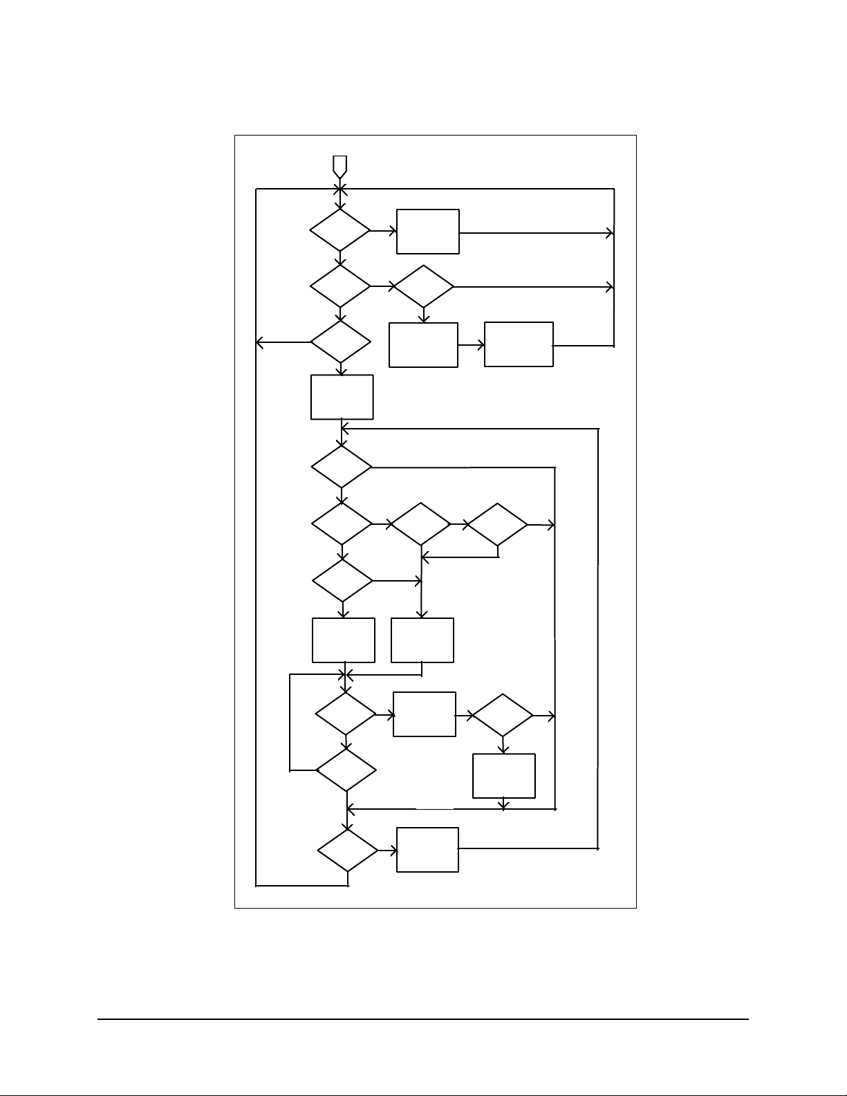
SMS-458B Modem Protection Switch Revision 2
Operation MN/SMS458B.IOM
MOD AUTO MODE
YES
HAS THE
VERIFY TIMER
TIMED OUT?
NO
ARE ANY
PRIMES
FLT’D?
YES
ARE THE
FLT’D
PRIMES
B/U’D?
NO
PUT FLT’D
PRIMES IN PRIORITY
ORDER. START WITH
HIGHEST PRIORITY.
IS THIS
FLT’D
PRIME B/U’D?
NO
IS A
B/U
AVAILABLE?
YES
IS
THE B/U
ON STAND-BY
FOR THIS
PRIME?
YES
VERIFY B/U
CONFIGURATION.
UPDATE IF
NECESSARY.
(SERIAL REMOTE
NOT AVAILABLE)
YES
OF THE NEXT MOD.
NO
PROGRAM B/U (s)
FOR HIGH ES T
PRIORITY CHANNEL(s).
(SERIAL REMOTE NOT
AVAILABLE)
YES
NO
PRIOIRTY PRIME
NO
CONFIGURATION
FOR THIS PRIME.
(SERIAL REMOTE
NOT AVAILABLE)
VERIFY THE
CONFIGURATION
(SERIAL REMOTE
NOT AVAILABLE)
ARE THE
B/U (s) ON
STAND-BY?
NO
IS A
LOWER
B/U’D?
YES
PROGRAM B/U
WITH THE
NO
YES
PLACE B/U (s) IN
STAND-BY MODE.
INDICATE WITH “-” ON
FRONT PANEL
IS A
NON-FLT’D
PRIME B/U’D?
NO
YES
WAIT FOR ALL
IS THE
B/U MOD
FLT’D?
YES
NO
HAS
THE 100 ms
TIMER TIMED
OUT?
YES
ARE
OTHER
PRIMES
FLT’D?
NO
APPLICABLE TIMERS.
NO
YES
FLT’D PRIME IN THE
INDICATE PRIME
WITH “#” ON
FRONT PANEL
MOD
GO TO NEXT
PRIORITY ORDER.
IS THE
PRIME STILL
FLT’D?
YES
PLACE B/U ON-LINE
FOR FLT’ D PR I ME
WITH “->“ ON
FRONT PANEL.
NO
Figure 3-3. SMS-458B Switching Algorithm Flow Chart Demodulator
3–20
Page 57
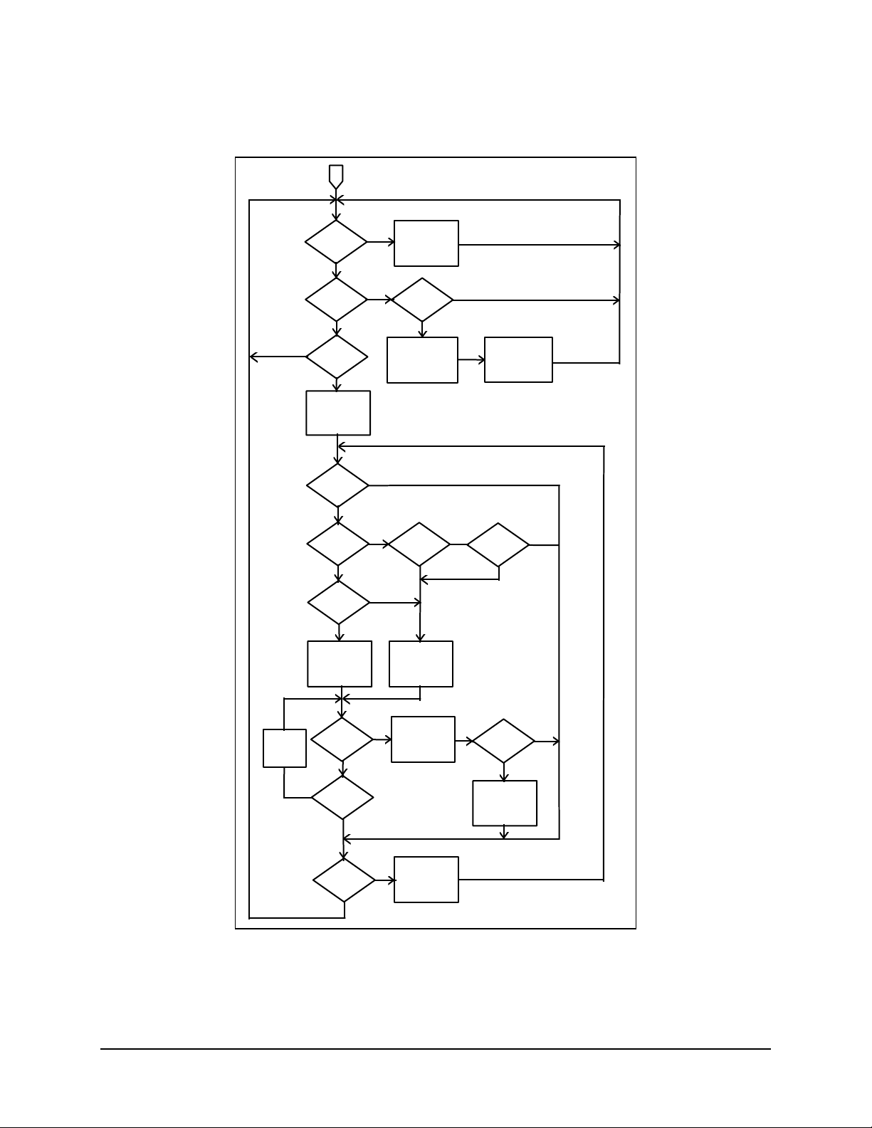
SMS-458B Modem Protection Switch Revision 2
Operation MN/SMS458B.IOM
MOD AUTO MODE
YES
HAS THE
VERIFY TIMER
TIMED OUT?
NO
ARE ANY
PRIMES
FLT’D?
YES
ARE THE
FLT’D
PRIMES
B/U’D?
NO
PUT FLT’D
PRIMES IN PRIORITY
ORDER. START WITH
HIGHEST PRIORITY.
IS THIS
FLT’D
PRIME B/U’D?
NO
IS A
B/U
AVAILABLE?
YES
IS
THE B/U
ON STAND-BY
FOR THIS
PRIME?
YES
VERIFY B/U
CONFIGURATION.
UPDATE IF
NECESSARY.
(SERIAL REMOTE
NOT AVAILABLE)
YES
OF THE NEXT MOD.
NO
PROGRAM B/U (s)
FOR HIGHES T
PRIORITY CHANNEL(s).
(SERIAL REMOTE NOT
AVAILABLE)
YES
NO
PRIOIRTY PRIME
NO
PROGRAM B/U
CONFIGURATION
FOR THIS PRIME.
(SERIAL REMOTE
NOT AVAILABLE)
VERIFY THE
CONFIGURATION
(SERIAL REMOTE
NOT AVAILABLE)
ARE THE
B/U (s) ON
STAND-BY?
NO
IS A
LOWER
B/U’D?
YES
WITH THE
NO
YES
PLACE B/U (s) IN
STAND-BY MODE.
INDICATE WITH “-” ON
FRONT PANEL
IS A
NON-FLT’D
PRIME B/U’D?
NO
YES
WAIT FOR ALL
HAS THE
ONLINE
DELAY TIMER
TIMED OUT?
NO
IS THE
B/U MOD
FLT’D?
YES
HAS
THE 500 ms
TIMER TIMED
OUT?
YES
ARE
OTHER
PRIMES
FLT’D?
NO
APPLICABLE TIMERS.
NO
YES
FLT’D PRIME IN THE
INDICATE PRIME
WITH “#” ON
FRONT PANEL
MOD
GO TO NEXT
PRIORITY ORDER.
Figure 3-4. SMS-458B Switching Algorithm Flow Chart Modulator
3–21
IS THE
PRIME STILL
FLT’D?
YES
PLACE B/U ONLINE
FOR FLT’D PRIME
WITH “->“ ON
FRONT PANEL.
NO
Page 58

SMS-458B Modem Protection Switch Revision 2
Operation MN/SMS458B.IOM
3.4.6.1 Modulator Operation Fault
The fault menu displays MOD fault(s) when a modulator backup switching operation
failure occurs. The messages will be as follows:
BK-UP FAULT MOD X
(where X = 1 to 4)
3.4.6.2 Demodulator Operation Fault
The fault menu displays DEMOD fault(s) when a demodulator backup switching
operation failure occurs. The messages will be any of the following:
BK-UP FAULT DMD X
ALL DMDS D/L X FAULTED.
(where X = 1 to 4)
(where X = 1 to 4)
3.4.6.3 M:N Faults
The fault menu displays M:N fault(s) when a communication, configuration, setup,
and/or power supply failure occurs. The messages will be any of the following:
MODEM X COMM FAILURE
MODEM B1 COMM FAILURE
CONFIG VERIFY ERROR M (or D) X
CONFIG VERIFY ERROR BM (or BD) 1
BK-UP M (or D) 1 NOT COMPATIBLE
PRIME M (or D) X NOT COMPATIBLE
NO ADDRESS FOR PRIME X
*NO ADDRESS FOR C/U X
NO ADDRESS FOR BK-UP 1
*NO ADDRESS FOR C/U B 1
NO INTERFACE FOR PRIME X
NO INTERFACE FOR BK-UP 1
NO D/L FOR DMD X
NO CONFIG FOR PRIME M (or D) X
NO CONFIG FOR BK-UP M (or D) 1
+12V FAILURE
-12V FAILURE
+5V FAILURE
POWER SUPPLY 1 FAULT
POWER SUPPLY 2 FAULT
Where X = 1 through 4
Note: These faults appear only if an external channel unit is selected.
3–22
Page 59

SMS-458B Modem Protection Switch Revision 2
Operation MN/SMS458B.IOM
3.4.6.4 Battery Faults
The fault menu displays BATTERY fault when a battery failure occurs in the switch. The
message will be as follows:
M & C BATTERY FAULT
3.4.7 Front Panel Theory of Operation
The Front Panel Control module contains:
• 48-character, dual row LCD display
• 16-key keypad
• 9 LEDs
• Audible buzzer
• Peripheral logic to interface with the M&C module
The display, LEDs, and buzzer are mapped into address space of the external bus
structure. The display updates every second, and the LEDs and buzzer update as needed.
Any keypad activity provides an interrupt to the processor, which then scans the keypad.
After the input has been recognized, the processor takes the appropriate action.
3–23
Page 60

SMS-458B Modem Protection Switch Revision 2
Operation MN/SMS458B.IOM
This page is intentionally left blank.
3–24
Page 61

Chapter 4. THEORY OF
This chapter describes switch theory of operation.
4.1 Monitor and Control
4.1.1 General
A sophisticated microcontroller performs the monitor and control functions of the switch.
The module, called the Monitor and Control (M&C), plugs into slot 5 of the switch
chassis, and is shown in Figure 4-1.
The M&C monitors the switch configuration and updates other modules within the switch
as required. Switch configuration parameters are stored in battery-backed RAM to
provide total recovery after a power-down. The switch gathers status and provides
extensive fault monitoring. A local front panel interface and a remote communications
interface provide user access to all switch functions.
OPERATION
4–1
Page 62

SMS-458B Modem Protection Switch Revision 2
Theory of Operation MN/SMS458B.IOM
Figure 4-1. Monitor and Control
4.1.2 Description of Options
4.1.2.1 M&C Serial Interface
The M&C communicates with the address decoder/driver through an EIA-232 interface.
Set the M&C for EIA-232 operation as follows:
1. Remove JP1, JP2, and JP3.
2. Install JP4, JP5, and JPX.
3. Install JP7 at EIA-232 location.
4–2
Page 63

SMS-458B Modem Protection Switch Revision 2
Theory of Operation MN/SMS458B.IOM
4.1.2.2 Remote Baud Rate
The 8-position switch pack SP1 on the M&C module programs the external remote serial
communications baud rate and parity. Set the switches to ON (nearer the PCB) or OFF
(away from the PCB) to select parity and baud rate.
SP1 switch position 1 (SP1-1) sets the parity:
• OFF = even parity
• ON = odd parity
SP1 switch positions 2, 3, and 4 (SP1-2, SP1-3, and SP1-4) set the baud rate as follows:
Baud SP1-2 SP1-3 SP1-4
110 ON ON ON
150 ON ON OFF
300 ON OFF ON
600 ON OFF OFF
1200 OFF ON ON
2400 OFF ON OFF
4800 OFF OFF ON
9600 OFF OFF OFF
4.1.2.3 Remote Address
The switch connects to an EIA-485 remote communication link. To communicate on this
link, each switch and modem must have a unique address between 1 and 255.
Note: “0” cannot be a device address, as it is the global address for all devices.
To program an address, use the 8-position switch pack, SP2, on the M&C module.
Addresses are binary coded numbers:
• Switch position 1 (SP2-1) is the most significant bit.
• Switch position 8 (SP2-8) is the least significant bit.
4–3
Page 64

SMS-458B Modem Protection Switch Revision 2
Theory of Operation MN/SMS458B.IOM
To turn ON any switch, move it to the position closer to the PCB. See the following
examples.
Address SP2-1 SP2-2 SP2-3 SP2-4 SP2-5 SP2-6 SP2-7 SP2-8
1 OFF OFF OFF OFF OFF OFF OFF ON
3 OFF OFF OFF OFF OFF OFF ON ON
5 OFF OFF OFF OFF OFF ON OFF ON
9 OFF OFF OFF OFF ON OFF OFF ON
17 OFF OFF OFF ON OFF OFF OFF ON
33 OFF OFF ON OFF OFF OFF OFF ON
65 OFF ON OFF OFF OFF OFF OFF ON
129 ON OFF OFF OFF OFF OFF OFF ON
255 ON ON ON ON ON ON ON ON
4.1.2.4 External Remote Serial Interface Selection
An EIA-485 or EIA-232 communications link on the address decoder/driver module
provides remote serial interface for all switch functions.
EIA-485 interface allows up to 32 devices to operate on a common communication
The
link. Each device must have a discrete address (there are 255 discrete addresses). EIA232 communication is only possible with a single device. During configuration setup, the
switch is configured for EIA-232 communication, whether EIA-232 or EIA-485
communication is desired. See Figure 4-1 for location of the switches.
Use M&C module switch pack SP1 switch 5 (SP1-5) to configure each switch for
external remote interface type, either EIA-485 or EIA-232. The ON position (nearer the
PCB) selects EIA-232 interface and OFF selects EIA-485.
4.1.2.5 Battery
A rechargeable battery on the M&C module allows it to retain configuration and status
information for up to 30 days without prime power. M&C module jumper JP6 connects
battery power to the backup RAM. During normal operation, this jumper should be in the
ON position.
Should the switch be powered-down, the M&C microcontroller performs the following
sequence:
1. Upon power-up, the M&C microcontroller checks the battery-backed RAM for
valid data. If valid data has been retained, the M&C implements the RAM-stored
switch configuration.
2. If the battery-backed RAM fails the valid data test, the switch loads default
settings from ROM.
4–4
Page 65

SMS-458B Modem Protection Switch Revision 2
Theory of Operation MN/SMS458B.IOM
Note: JP8 external battery jumper is not supported in the switch chassis, and therefore
must be set to the OFF position.
4.1.2.6 Error Response Switch
The Error Response function is an error message function that indicates that the
command sent cannot be carried out because local processing is utilizing the modem
control bus, local keyboard control, etc.
SP1 position 6 is the error response switch. The “ON” position enables the error response
function, and the “OFF” position disables the error response function.
4.1.2.7 External I/O Interrupt Arbitration
The switch does not use the external I/O interrupt arbitration function.
Note: JP12, JP13, and JP14 must be in the “LEFT” position to disable this function.
4.1.3 Modem Control Interface Specification
The modem control interface is an EIA-485 serial communication link, which allows the
switch to maintain control of backup modems and verify the configuration of the prime
and backup modems.
The EIA-485 interface permits up to 32 devices to operate on a common communication
link, however, only modems and channel units may be connected to this communication
link. External remote communication to the modems and switch is done through the
external remote interface.
The user cannot configure the parameters of the EIA-485 interface. The baud is fixed at
9600 and parity is even. All devices communicating with the switch must have their
remote control interface configured to those parameters. Each modem and channel unit
must have a unique address.
For details of remote interface specification and configuration for each device, refer to
the respective Installation and Operation Manual.
4.1.4 Relay-Remote Interface Specification
4–5
Page 66

SMS-458B Modem Protection Switch Revision 2
Theory of Operation MN/SMS458B.IOM
4.1.4.1 Scope
This section defines the protocol and the word and command structure of the relayremote interface.
4.1.4.2 General
The relay-remote input (J6) allows the user to execute a limited number of mode and
online commands (refer to Section 2.2.5 for connector location and pinout).
These commands are a series of 4-bit words. The switch has a 4-line parallel interface
with pull-up resistors (10 K
to pin 25 of J6 can generate logic low inputs. The inputs can also be driven directly from
TTL or CMOS family devices.
The M:N switch recognizes a word 100 msec after the change of state is detected on the
parallel interface. The words must be held for 200 msec, and should not be sent faster
than 500 msec or slower than 10-second intervals. The word can be repeated any number
of times, but the switch only detects it the first time it is sent. The following section
describes the commands that can be executed.
Ω to +5V). Thus, open inputs are logic high, and connecting
4.1.4.3 Command Structure
A command to the switch consists of three or four words sent on the four parallel lines in
one of the following formats:
• Non-return-to-zero (NRZ)
• Return-to-zero (RZ)
The command sequence begins with the START word. The switch recognizes each word
by changes of state at the relay-remote inputs. After debounce, the switch identifies the
word. If all words are valid and the EXECUTE word is received, the switch performs the
command.
The command words START and EXECUTE are defined in Table 4-1.
4–6
Page 67

SMS-458B Modem Protection Switch Revision 2
Theory of Operation MN/SMS458B.IOM
Table 4-1. Relay-Remote Command Words
Input Lines
Command Word Rem3 Rem2 Rem1 Rem0
AUTO N N C N
REMOTE N N N C
B/U MOD 1 C C N C
B/U DEMOD 1 C N N C
START C C C C
EXECUTE C C N N
Notes:
1. C = Change of state.
2. N = No change of state.
Target words are defined in Table 4-2.
Table 4-2. Modem Target Words
Target
Modem
Rem3 Rem2 Rem1 Rem0
1 N N N C
2 N N C N
3 N N C C
4 N C N N
Input Lines
Notes:
1. C = Change of state.
2. N = No change of state.
4–7
Page 68

SMS-458B Modem Protection Switch Revision 2
Theory of Operation MN/SMS458B.IOM
Table 4-3 describes the six command functions that can be executed.
Table 4-3. Relay-Remote Command Functions
Function Description
AUTO Executed only from REMOTE mode. This function places the switch
in the automatic mode of operation.
REMOTE Executed from any operating mode other than REMOTE; must be
executed before any other relay-remote function. This function
places the switch in the remote mode of operation.
BACKUP MOD 1 Executed only from REMOTE mode. This function is used to place
backup modulator 1 online when it precedes a target word or offline
when it precedes EXECUTE.
BACKUP DEMOD 1 Executed only from REMOTE mode. This function is used to place
backup demodulator 1 online when it precedes a target word or
offline when it precedes EXECUTE.
A valid command structure consists of words in the following order:
1. The START word begins all messages.
2. The COMMAND word follows the start word.
3. If the command affects the online or offline status of a prime modulator or
demodulator, the next 4-bit word must be the TARGET word. The format for the
target word is the BCD number for the prime modulator or demodulator. The
target word is not sent if the backup is to be taken offline or AUTO or REMOTE
mode is selected.
4. The EXECUTE word follows the target (or command) word.
The command words must be sent to the switch with no more than 10 seconds between
words for the switch to recognize a command. If the interval exceeds 10 seconds, the
M&C resets the word buffer and waits for the next START word.
If an incorrect word is sent, begin the message sequence again with the START word.
This word restarts the message sequence.
4–8
Page 69

SMS-458B Modem Protection Switch Revision 2
Theory of Operation MN/SMS458B.IOM
Table 4-4 shows some relay-remote command examples.
Table 4-4. Relay-Remote Command Examples
Input Lines
Command Words Rem3 Rem2 Rem1 Rem0 Comments
START C C C C Places the M:N in the
REMOTE N N N C the remote mode.
EXECUTE C C N N
START C C C C Places B/U mod 1
B/U MOD 1 C C N C online for prime 2.
TARGET PRIME 2 N N C N
EXECUTE C C N N
START C C C C Places B/U demod 1
B/U DEMOD 1 C N N C online for prime 4.
TARGET PRIME 4 N C N C
EXECUTE C C N N
START C C C C Places the M:N in the
AUTO N N C N auto mode.
EXECUTE C C N N
Notes:
1. C = Change of state.
2. N = No change of state.
3. Mod = Modulator.
4. Demod = Demodulator.
4.1.5 Fault Interface Specification
Note: These contacts report summary status. To determine the exact fault, the user must
make further inquiry, as described in Section 3.4.6.
This section defines the protocol and format structure for monitoring the fault status
interface of the switch.
The relay-remote/fault rear panel connector (J6) provides interface for fault status
information. (See Section 2.2.5 for connector location and pinout information.)
Three non-latching relays with form-C contacts show:
• Controller status
• M:N status
• Demodulator signal status
4–9
Page 70

SMS-458B Modem Protection Switch Revision 2
Theory of Operation MN/SMS458B.IOM
4.1.5.1 Controller Fault
A controller fault is a catastrophic failure that renders the switch nonfunctional. A timer
on the M&C periodically sets a monostable, which controls the fault relay.
The controller fault relay NC and COM contacts close when:
• No power is applied to the switch.
• When the M&C fails to set the monostable.
During normal operation (when no fault occurs), the relay NC and COM contacts are
open and the NO and COM contacts are closed.
4.1.5.2 M:N Fault
An M:N fault is any failure of backup operation, communication, configuration, and/or
setup that may (or may not) render the switch nonfunctional.
During normal operation or power-off, the relay is de-energized (COM to NC). When
any failure occurs, the relay energizes (COM to NO). It remains energized until the
failure is eliminated.
4.1.5.3 Demodulator Signal Fault
A demodulator signal fault is the failure of all active demodulators on the indicated
downlink to acquire and lock to their signals. The fault alarm indicates a possible down
converter system failure causing loss of IF to the demodulators. During normal operation
or power-down, the relay is de-energized (COM to NC).
When all demodulators indicate loss of carrier, the relay energizes (COM to NO). The
relay remains energized until the failure is eliminated.
4.1.6 Online Status Specification
This section defines the protocol and format for reporting the online status of the switch.
The M&C commands the online telemetry module to report online status for all active
prime modulators and demodulators. The status is reported as form-C relay contact to the
online status connectors (J4 and J5) on the rear panel (see Section 2.2.4 for connector
locations and pinouts).
The active modulators online status is indicated at J4 by form-C relay contacts. When the
prime is online or power is off, the relay is de-energized (COM to NC). When a backup
modulator goes online for that prime, the relay energizes (COM to NO).
4–10
Page 71

SMS-458B Modem Protection Switch Revision 2
Theory of Operation MN/SMS458B.IOM
The active demodulators online status is indicated at J5 by form-C relay contacts. When
the prime is online or power is off, the relay is de-energized (COM to NC). When a
backup demodulator is online for that prime, the relay is energized (COM to NO).
4.1.7 Monitor and Control Theory of Operation
The Monitor and Control module uses an Intel 80C31 microcontroller operating at 5.5295
MHz. The microsystem supports 128K bytes of Read Only Memory (ROM) for code and
64K bytes of Random Access Memory (RAM) for data.
Of the 64K bytes, only 8K is used for RAM, the remaining 56K is used for memorymapped I/O.
Memory-mapped I/O includes:
• Real time clock/memory
• 8-channel analog-to-digital converter
• External buffered bus structure for overall switch control and status gathering
The 80C31 microcontroller supports a serial asynchronous communications channel
(EIA-232C) with a maximum baud rate of 9600 bit/s using the 5.5295 MHz reference.
A rechargeable battery maintains the system real time clock and switch configuration
through power-down situations.
Memory is maintained up to 30 days without power.
A full battery charge is attained after the modem is powered on for 48 hours.
4.2 Interface Switches
4.2.1 IDR/G.703 Interface Switch
4.2.1.1 General Description
The IDR/G.703 interface switch module switches all interface signals by relay. The prime
interface switch module (Figure 4-2) has two 50-pin female D connectors and four BNC
connectors. The terrestrial interface J1, J2, and J5 (top) is a DCE interface, and the prime
modem interface J3, J4, and J6 (bottom) is a DTE interface. The prime interface switch
module can plug into any of the even-numbered interface switch module slots (A2, A4,
A6, and A8) on the left side of the lower-rear panel.
The backup interface switch module (Figure 4-3) has one 50-pin female D connector and
two BNC connectors. The backup modem interface connectors J1 and J2 carry the G.703
4–11
Page 72

SMS-458B Modem Protection Switch Revision 2
Theory of Operation MN/SMS458B.IOM
data, and J3 is the IDR with ESC interface. The backup interface switch module can plug
into A10 slot only.
When the interface switch module is powered down or in the default position, all prime
interface switch module signals are routed between the terminal equipment and the prime
modem.
Modulator and/or demodulator signals can be independently switched to the backup
modem interface switch module. The fault lines from the modem connector are routed
through the interface switch modules to the M&C.
When using G.703 data switching, a buffered set of transmit data (SD) signals is switched
to the “hot standby” backup modulator and demodulator during prime modem operation,
or to the offline prime modulator and demodulator when a backup operation occurs.
4.2.1.2 Specification (IDR/G.703)
Circuits Supported SD, RD, EXC, TXD, TXC, TXO, RXD, RXC, RXO, BWO 1-4,
BWI 1-4, A1I, A1O, A2I, A2O, DEMOD FAULT.
Switching Format All signals switched with dry contacts.
Contact Arrangement Modulator signals: 16 poles.
Demodulator signals: 26 poles.
Spares: 2 poles.
Demodulator signals: 26 poles.
Spares: 2 poles.
Synthesized Data Source All ones Data Pattern.
4–12
Page 73

SMS-458B Modem Protection Switch Revision 2
Theory of Operation MN/SMS458B.IOM
4.2.1.3 Connector Pinout
The IDR interface uses a 50-pin female D connector. Screw locks and latching blocks
provide mechanical security of the mating connector.
Signal Function Name Pin #
Ground GND 1, 2
8 kbit/s TX Data TXD-A
TXD-B
8 kHz TX Clock Out TXC-A
TXC-B
1 kHz TX Octet In TXO-A
TXO-B
8 kbit/s RX Data RXD-A
RXD-B
8 kHz RX Clock Out RXC-A
RXC-B
1 kHz RX Octet Out RXO-A
RXO-B
Backward Alarm 1 Out BWO1-C
BWO1-NC
BWO1-NO
Backward Alarm 2 Out BWO2-C
BWO2-NC
BWO2-NO
Backward Alarm 3 Out BWO3-C
BWO3-NC
BWO3-NO
Backward Alarm 4 Out BWO4-C
BWO4-NC
BWO4-NO
Backward Alarm 1 In BWI1 12
Backward Alarm 2 In BWI2 13
Backward Alarm 3 In BWI3 14
Backward Alarm 4 In BWI4 15
ADPCM 1 Audio In A1I-A
A1I-B
ADPCM 1 Audio Out A1O-A
A1O-B
ADPCM 2 Audio In A2I-A
A2I-B
ADPCM 2 Audio Out A2O-A
A2O-B
Demod Fault Relay DF-C
DF-NO
Modulator Fault MF 49
Demodulator Fault DF 33
Deferred Maintenance Alarm DMA 17
37
38
21
22
4
5
39
40
23
24
6
7
8
25
41
9
26
42
10
27
43
11
28
44
45
29
46
30
47
31
48
32
16
50
4–13
Page 74

SMS-458B Modem Protection Switch Revision 2
Theory of Operation MN/SMS458B.IOM
Note: MF and DF inputs are located only on the prime and backup modem
interface connectors, not the terrestrial data connectors.
4–14
Page 75

SMS-458B Modem Protection Switch Revision 2
Theory of Operation MN/SMS458B.IOM
TERRESTRIAL
DATA I/O
TRANSMIT ESC
RECEIVE ESC
RECEIVE EXTERNAL
REFERENCE CLOCK
J5
J1
J2
THE RELAYS ARE SHOWN IN THE NON-ENERGIZED
NOTE:
POSITION CONNECTING THE TERRESTRIAL DATA AND
PRIME MODEM CONNECTORS TOGETHER. STANDBY (S/B)
SIGNALS ARE ROUTED TO THE OFFLINE BACKUP MODEM.
Figure 4-2. Prime IDR/G.703 Interface Switch
TX
RX
TRANSMIT ESC
TRANSMIT DATA
RECEIVE ESC
RECEIVE DATA
RECEIVE EXTERNAL
REFERENCE CLOCK
MOD AND DEMOD FAULTS
TX RELAYS
RX RELAYS
TRANSMIT ESC
RECEIVE ESC
RECEIVE EXTERNAL
REFERENCE CLOCK
FAULTS
TX DATA
RX DATA
RX DATA
TX DATA
INSTRUCTION
DECODER
DATA SWITCH
MOTHERBOARD
PRIME C/U
DATA I/O
J6
J3
J4
BACK/UP C/U
DATA I/O
DATA SWITCH
MOTHERBOARD
TRANSMIT ESC
RECEIVE ESC
RECEIVE EXTERNAL REFERENCE CLOCK
MOD AND DEMOD FAULTS
TRANSMIT DATA
RECEIVE DATA
Figure 4-3. Backup IDR/G.703 Interface Switch
4–15
Page 76

SMS-458B Modem Protection Switch Revision 2
Theory of Operation MN/SMS458B.IOM
4.3 Address Decoder/Driver
4.3.1 General
The address decoder/driver is a 10.5 x 3.5 inches module (Figure 4-4) that fits into
slot 4 of the front-upper section of the switch chassis. Its functions include:
• Address decoding of the external address bus
• External data bus buffering
• Serial communications interface
• Modem fault interface
• Fault outputs
Refer to Figure 4-5 for a block diagram of the address decoder/driver card.
Figure 4-4. Address Decoder/Driver
4–16
Page 77

SMS-458B Modem Protection Switch Revision 2
A
A
A
A
Theory of Operation MN/SMS458B.IOM
DATA BUS AND
CONTROL SIGNALS
20
PRIME AND
BACKUP
FAULT INPUTS
DDRESS
DDRESS
LATCH
DECODE AND
DATA BUS
BUFFER
SYNCHRONOUS
COMMUNICATIONS
INTERFACE
DEVICE
EXT INTERFACE CONTROL
SYNCHRONOUS
COMMUNICATIONS
INTERFACE
DEVICE
MODEM INTERFACE CONTROL
CONTROL BUS
Figure 4-5. Address Decoder/Driver
INTERNAL
MUX
EXT CONTROL BUS
M:N
FAULT
DMD SYSTEM
FAULT
CONTROL
FAULT
RELAY-REMOTE
INTERFACE
RS-485
'1'
RS-232
RS-485
DSR
RXD
TXD
3
3
3
4
4.3.2 Specifications
Address Decoding 2K bytes of address bus decoded to 24 discrete channels.
Data Bus Buffering 8 bits to all peripheral devices.
Communication Interface:
Remote interface
Relay-remote interface
Modem Control Interface
Modem Fault Interface 10 lines for Muxed modulator and demodulator faults.
Fault Outputs Controller Fault: Form-C.
4–17
EIA-485 or EIA-232, 255 addresses, 110 to 9600 baud.
4 lines (parallel).
EIA-485, 255 addresses, 9600 baud.
(Dual ACIAs on the AS/1048 board enable simultaneous
communication on both Remote and Modem control
interfaces.)
System Fault: Form-C.
Demod Signal Fault: Form-C.
Page 78

SMS-458B Modem Protection Switch Revision 2
Theory of Operation MN/SMS458B.IOM
4.3.3 Address Decoder/Driver Theory of Operation
The address decoder/driver interfaces the:
• M&C data bus
• Address bus
• Control lines
• Serial interface
Addresses of the peripheral devices, both on and off of this card, are latched and decoded
to select each device. The data bus is bidirectionally buffered to and from the M&C card.
The data bus and decoded address lines are buffered off this card as they are output to the
other modules.
The address decoder/driver formats the serial data communication to and from the M&C.
All interface drivers and receivers for external communication are on this module.
The fault lines from the interface switch modules are routed to this card. The M&C reads
the faults at regular intervals to update its own registers.
The address decoder/driver card contains the following fault relays:
• M:N summary
• Demodulator signal
• Controller
The M&C control the M:N summary and demodulator signal fault relays directly.
A “watchdog” timer controls the controller fault. The M&C must reset the “watchdog”
timer at regular intervals, or the controller fault will set.
4–18
Page 79
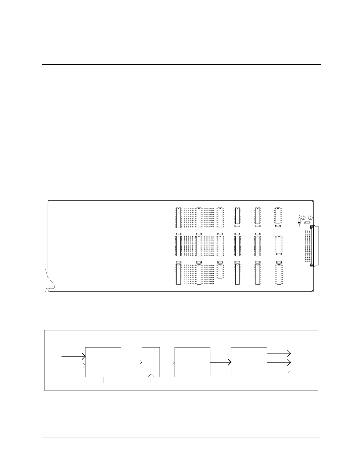
SMS-458B Modem Protection Switch Revision 2
A
_
Theory of Operation MN/SMS458B.IOM
4.4 IF Switch Driver
The IF switch driver (Figure 4-6) is a 10.5 x 3.5 inches module that fits into slot 3 of the
upper-front section of the switch chassis. It controls activation of the baseball switches on
the IF Switch card.
Both +5V and +12V are utilized on this card.
The M&C uses the address decoder/driver with an 8-bit data bus and one device select
line to control the switch driver. The switch driver decodes commands from the M&C
card and activates the appropriate baseball switches on the IF switch in accordance with
these commands.
Refer to Figure 4-7 for a block diagram of the IF Switch Driver card.
IF SWITCH RELAY DRIVER
SMS-758
FSCM 4J515
S/1316 REV ______
S/N ________________
FROM M&C
DATA BUS
X 8
CARD SEL
Figure 4-6. Switch Driver
TO BASEBALL
M&C
INTF
L
A
T
C
H
COMMAND
DECODE
X 22
DRIVERS
+12V
X 22BASEBALL
SWITCH 1
TO BASEBALL
SWITCH 22
TO IF SWITCH
Figure 4-7. IF Switch Driver Block Diagram
4–19
Page 80

SMS-458B Modem Protection Switch Revision 2
Theory of Operation MN/SMS458B.IOM
4.5 Data Switch Controller Card
The data switch controller (Figure 4-8) resides in the data switch (lower) section in the
switch. The card performs two main functions:
• The card decodes M&C commands in order to control the data switching matrix.
• The card contains a synthesized data source, which is used to keep a data stream
to the offline modulator. This is done so the offline modulator does not show a
faulted condition due to loss of data.
Since the data that is fed to the offline modulator as an all 1s pattern, the modem will
show AIS indication. The data rate is programmed automatically when the user programs
the switch. The on-board oscillator has a fine tune adjustment, R29 (which is set at the
factory), for the oscillator frequency, and can be monitored by connecting a frequency
counter to J3.
The data rate of the oscillator frequency can be programmed from 32 to 45 Mbit/s.
FROM M&C
DATA BUS
X 8
CARD SEL
CRYSTAL
OSCILLATOR
R29
M&C
INTF
SYNTH
L
A
T
C
H
COMMAND
DECODE
X 22
LEVEL
FORM ATER
Figure 4-8. Data Switch Controller Card
BASEBALL
DRIVERS
X 22
TO BASEBALL
SWITCH 1
TO BASEBALL
SWITCH 22
TO IF SWITCH+12V
ALL ONES
DATA
4–20
Page 81

SMS-458B Modem Protection Switch Revision 2
Theory of Operation MN/SMS458B.IOM
4.6 IF Switch
4.6.1 General
The IF switch (Figure 4-9) is a 14.0 x 5.0 inches module that fits in the lower section of
the switch chassis. It isolates the backup modulator’s IF outputs and connects the backup
modulator’s output in place of any of the prime modulators when a fault is detected. It
also connects the IF backup demodulators inputs to one of four downlink inputs.
There are two IF switch cards in the switch:
• One for transmit switching.
• One for receive switching.
4.6.2 Specifications
Power source +12V
Isolation
Balance
Loss
≥ 60 dB
± 0.25 dB
≤ 1 dB
4.6.3 IF Switch Theory of Operation
The IF switch contains 22 baseball switches that comprise the IF switching matrix. Each
baseball switch is controlled separately by the M&C card via the switch driver card.
The modulator section of the switching matrix contains 16 of the switches that control the
backup modulator outputs to switch to any of the eight prime modulator outputs if a fault
is detected by the M&C card. The operator can also manually select a backup modulator
to switch in for any of the prime modulators via the front panel (refer to Section 3.1 and
3.4.5.3).
The demodulator section of the switching matrix contains the remaining six switches.
They connect the IF backup demodulator inputs to any of four downlink inputs for use
when any of the prime demodulators are faulted. The operator can also manually select a
backup demodulator to be online for any of the prime demodulators via the front panel.
Note: Only four prime modems may be used with this switch.
4–21
Page 82

SMS-458B Modem Protection Switch Revision 2
Theory of Operation MN/SMS458B.IOM
BU MOD 1
MOD 1
MOD 2
MOD 3
MOD 4
IF 1
IF 2
IF 3
IF 4
BACK-UP 1 IF OUTPUT
INPUTSOUTPUTS
DOWNLINK 4
DOWNLINK 3
DOWNLINK 2
DOWNLINK 1
DEMODULATOR SWITCH
Figure 4-9. IF Switch
DEMODULATOR S WITCH
BACKUP DEMOD 1
4–22
Page 83
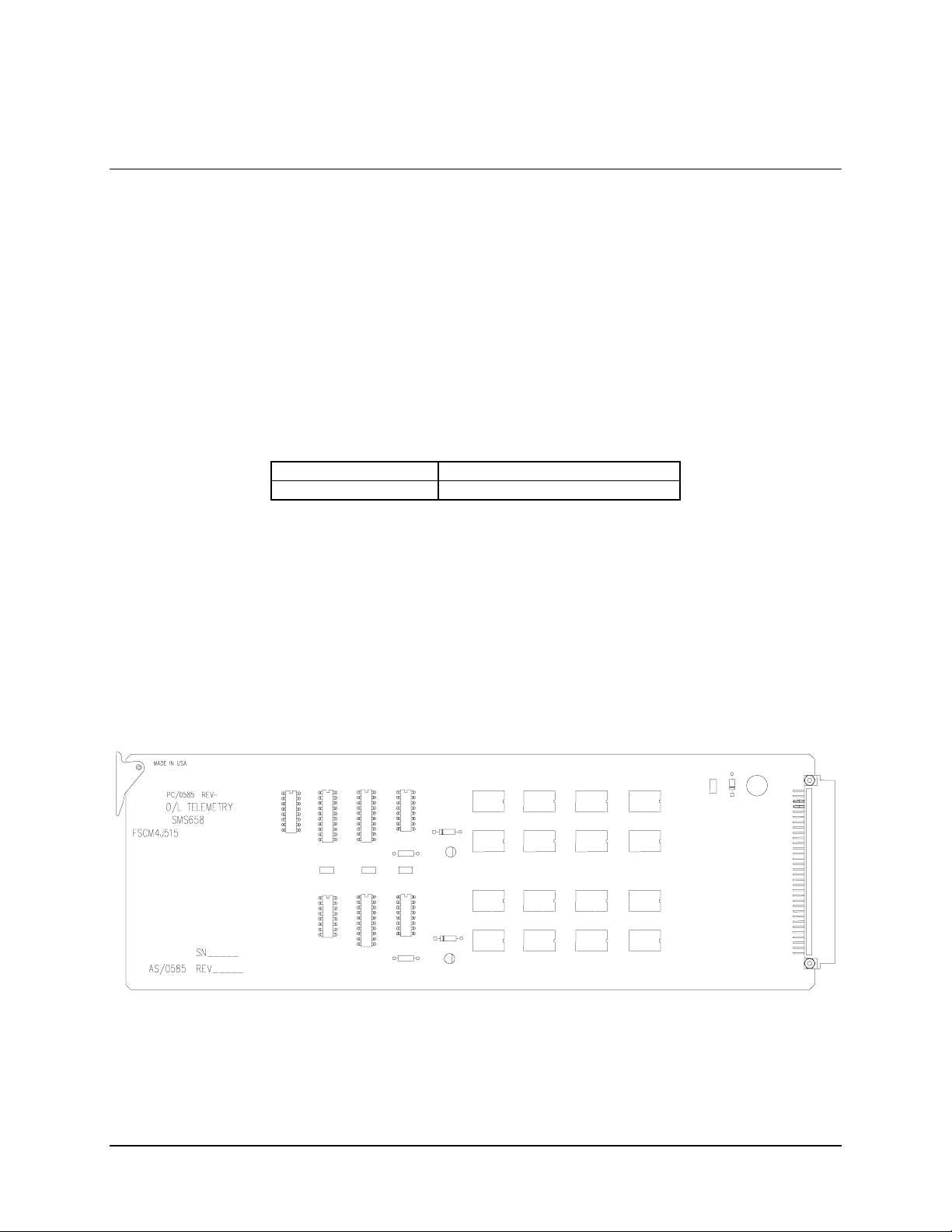
SMS-458B Modem Protection Switch Revision 2
Theory of Operation MN/SMS458B.IOM
4.7 Online Telemetry
4.7.1 General
The online telemetry (Figure 4-10) is a 10.5 x 3.5 inches module that fits into slot 6 of the
upper-front section of the switch chassis. It reports the online status of each prime
modulator and demodulator.
Refer to Figure 4-11 for a block diagram of the online telemetry.
4.7.2 Specifications
Number of Channels 8 modulator and 8 demodulator.
Switching Format Form-C contacts.
4.7.3 Online Telemetry Theory of Operation
The M&C controls the online telemetry module through the address decoder/driver with
an 8-bit data bus and 2 device select lines. Sixteen SPDT relays (Form-C) can be
switched to indicate the online status of 8 prime modulators and 8 prime demodulators.
Note: Only four prime modems may be used with this switch.
Figure 4-10. Online Telemetry
4–23
Page 84

SMS-458B Modem Protection Switch Revision 2
Theory of Operation MN/SMS458B.IOM
MOD 1
ONLINE
STATUS
DEMOD 1
ONLINE
STATUS
CONTROL BUS
INSTRUCTION
LATCH
RELAY
DRIVER
16
MOD 8
ONLINE
STATUS
DEMOD 8
ONLINE
STATUS
Figure 4-11. Online Telemetry Block Diagram
4–24
Page 85

SMS-458B Modem Protection Switch Revision 2
Theory of Operation MN/SMS458B.IOM
4.8 Power Supply
4.8.1 General
The power supply modules fit into slots 1 and 7 of the upper-front section of the switch
chassis (Figure 4-12). (In slot 7 the supply is inverted.)
The supplies are enclosed in a 10.5 x 3.5 x 2.5-inch wide metal frame that encloses the
power supply assembly, provides power switch access, and secures in the chassis.
To turn on the power supply, press the switch toward the “1” symbol on the front of the
frame.
The switch can operate with only one power supply turned on, but an M:N fault will
indicate that the other power supply is faulted.
The frame can accommodate many different manufacturers power supplies, thus
providing for different power input specifications.
4.8.2 Specifications
120 VAC and 220 VAC Operation
Input voltage 90 to 264 VAC
Input Frequency 47 to 63 Hz
Output Voltages and Current Capacity + 5V at 5A
Note: -48 Vdc operation is optional, and specifications will be provided upon request.
Automatic selection for 110 or 220V operation
+12V at 0.5A
-12V at 0.5A
4–25
Page 86

Page 87

Chapter 5. MAINTENANCE
This chapter describes switch faults and their probable causes.
5.1 Fault Descriptions
5.1.1 General
The FAULT menu, [NEXT], and [PREV] keys allow the operator determine the cause of
any switch faults indicated by a red LED on the switch front panel. The following
sections describe faults and their probable causes.
5.1.2 Modulator Operation Fault
A MOD fault occurs when a modulator backup operation fails. The cause of the failure
can be one of the following:
• More failed modulators than available backups.
• No compatible backup available.
• All backups are in use.
5–1
Page 88

SMS-458B Modem Protection Switch Revision2
Maintenance MN/SMS458B.IOM
5.1.3 Demodulator Operation Fault
A DEMOD fault occurs when a demodulator backup operation fails. Any of the
following can be the cause of failure:
• More failed demodulators than available backups.
• No compatible backup available.
• All backups are in use.
• All demodulators on a downlink faulted.
5.1.4 M:N Faults
An M:N fault occurs when a communication, configuration, setup, and/or power supply
failure occurs. Any of the following can be the cause of failure:
• Modem communication failure due to incorrect:
! Address
! Baud rate
! Parity
! Interface connection
• Failure to verify configuration data.
• Missing configuration data.
• A backup modulator or demodulator that is not compatible with any prime.
• A prime modulator or demodulator that is not compatible with any backup.
• A missing modem address specification.
• A missing channel unit address specification (version 2.02 or newer).
• A missing modem interface specification.
• A missing demodulator downlink specification.
• High or low +12V power supply.
• High or low -12V power supply.
• High or low +5V power supply.
• One of the power supplies is turned off.
5–2
Page 89

SMS-458B Modem Protection Switch Revision2
Maintenance MN/SMS458B.IOM
5.1.5 Battery Faults
Note: After the battery is recharged or replaced, the switch must be reconfigured.
A BATTERY fault indicates that a battery failure has occurred. The cause may be the
result of a low M&C battery.
A low battery alarm indicates that the battery voltage is below its specified level and that
the battery should be recharged or replaced. It does not necessarily indicate that memory
data will be lost if power is turned off, but it does indicate that data entered by the
memory at power-up is suspect.
5.2 Fault Isolation
The following tables list the procedures for clearing fault indications in the fault menu or
the remote interface (the remote interface messages are identified within parentheses).
The tables list the fault messages on the left and the procedures on the right. Perform the
steps in the order listed to clear the fault or to determine why the fault remains.
5.2.1 Modulator Operation
Faults Procedures
BK-UP FAULT MOD X
(MOF_BU_OP_FLT_x)
If no M:N faults exist:
Verify that the switch is in AUTO mode.
Verify that a backup modulator is available to backup all of the
faulted prime modulators.
Verify that the data cable between the switch and the modem
is connected to the correct connectors.
If an M:N fault exists, check M:N faults for communication,
configuration, and compatibility faults.
If there are faulted primes that are not backed up, the
modulator operation fault display will remain on.
5–3
Page 90

SMS-458B Modem Protection Switch Revision2
Maintenance MN/SMS458B.IOM
5.2.2 Demodulator Operation
Faults Procedures
BK-UP FAULT DMD X
(DOF_BU_OP_FLT_x)
ALL DMDS D/L X
FAULTED
(DL_FLT_y)
If no M:N faults exist:
Verify that the switch is in AUTO mode.
Verify that a backup demodulator is available to backup all of
the faulted prime demodulators.
Verify that the data cable between the switch and the modem
is connected to the correct connectors.
Verify that the IF cable between the switch demodulator
output and the modem IF input is connected to the correct
connectors.
If an M:N fault exists, check M:N faults for communication,
configuration, and compatibility faults.
Verify that the downlink assignments for the demodulator are
programmed in the modem configuration and properly
connected behind the patch panel.
Verify that the IF cables between the switch demodulator
outputs and the modem IF inputs are connected to the correct
connectors.
Verify that the IF cables between the down converter
equipment and the switch downlink inputs are connected to
the correct connectors.
If there are faulted primes that are not backed up or the
downlink signal is interrupted, the demodulator operation fault
display will remain on.
5–4
Page 91

SMS-458B Modem Protection Switch Revision2
Maintenance MN/SMS458B.IOM
5.2.3 M:N Operation
Faults Procedures
MODEM (B)X COMM FAILURE
(COM_FLT_(B)x)
CONFIG VERIFY ERROR M (or D) (B)X
(MOD_CONFIG_FLT_(B)x)
(DMD_CONFIG_FLT_(B)x)
PRIME (or BK-UP) M (or D) X NOT
COMPATIBLE
(MOD_COMPAT_FLT_(B)x)
(DMD_COMPAT_FLT_(B)x)
NO ADDRESS FOR PRIME (or BK-UP) X
(NO_ADX_(B)x)
NO ADDRESS FOR PRIME (or BK-UP) C/U X
(NO_ADX_C/U_(B)X)
NO INTERFACE FOR PRIME (or BK-UP) X
(NO_INTFC_(B)x)
NO D/L FOR DMD X
(NO_DL_x)
NO CONFIG FOR PRIME (or BK-UP) M (or D) X
(NO_MOD_CONFIG_(B)x)
(NO_DMD_CONFIG_(B)x)
Verify that the modem baud rate is set
to 9600.
Verify that the modem interface type is
RS-485.
Verify that the modem parity is even.
Verify that the modem address is
correctly entered in the switch system
configuration.
Verify that the modem control interface
cable between the switch and modems
is connected to the correct connectors.
Verify that the M&C in the switch is set
to RS-232.
Check the configuration of the indicated
modem: if modem configuration has
been changed, update configuration
data in switch memory.
Check the Data Rate/Code Rate of the
indicated modem and verify that the
utility menu data in the switch
corresponds to the modem setting. If
not, update the utility menu.
Check the selected modem. Verify that
the interface type selected in the
modem setup menu is compatible with
the backup (or prime) modem.
Enter the address for the indicated
modem in the system setup menu of the
switch.
Enter the address for the indicated
channel unit in the system setup menu of
the switch.
Enter the interface type for the indicated
modem in the modem setup menu of the
switch.
Enter the downlink assignment for the
indicated demodulator in the modem
setup menu.
Load the configuration for the indicated
modem in the configuration menu.
5–5
Page 92

SMS-458B Modem Protection Switch Revision2
Maintenance MN/SMS458B.IOM
+12V FAILURE, -12V FAILURE, +5V FAILURE
(+12V_FLT, -12V_FLT, +5V_FLT)
POWER SUPPLY 1 (or 2) FAULT
(PS_1(2)_FLT)
Check the power supplies and modules
for proper insertion into the motherboard
connectors.
The voltage limit comparators are not
user adjustable. Consult the factory if
the voltage failure alarm continues to be
displayed.
Check the power supplies for proper
insertion into the motherboard
connector.
Verify that the power switch on the
indicated power is in the on position.
Verify that the power cord for the
indicated power supply is plugged into
the chassis.
Check the fuse of the indicated power
supply.
The power supplies are not user
serviceable. Contact the factory if a
power supply failure is suspected.
5.2.4 Battery
Faults Procedures
M&C BATTERY FAULT
(M&C_BAT_FLT)
Check the position of the internal battery
jumper on the M&C board.
Check the battery for bent or displaced
leads.
The NiCad battery on the M&C board is
rechargeable and may require up to 48
hours to fully charge.
5–6
Page 93

SMS-458B Modem Protection Switch Revision2
Maintenance MN/SMS458B.IOM
5.3 Module Replacement
Turn off both power supplies before removing or inserting any module.
CAUTION
5.3.1 General
The modules in the switch are designed for easy replacement.
Note: All digital and IF signals will be routed to the prime modems when the switch
power is off. If any prime modem(s) is faulted and backed up, the backup modulator
and/or demodulator will go offline, interrupting service when power is lost.
The following modules can be removed and replaced in the field.
Power Supply Monitor and Control IF Switch Online Telemetry Switch Driver Interface Switches Address Decoder/Driver Data Switch Controller
5.3.2 Power Supply
The power supply modules are located in the upper-front section of the switch, slots 1
and 7. (The second power supply can remain on.)
1. Each power supply module is secured in the chassis with a No. 6 screw. Remove
the screw and pull the handle on the front of the module to remove the power
supply.
2. Insert the new power supply in the slot (invert the power supply for slot 7) and
press it in until fully seated. Install the No. 6 screw to secure the power supply in
place. Turn on power switch.
5–7
Page 94

SMS-458B Modem Protection Switch Revision2
Maintenance MN/SMS458B.IOM
5.3.3 IF Switch
The IF switch modules are located in the lower-front section of the switch.
1. Remove screws holding the board on the standoffs in the lower section of the
switch.
2. Disconnect the cables to each IF switch module one at a time.
3. Carefully remove the module from the inside of the lower-front section.
4. Replace the IF switch and connect all the connectors to their proper location.
5. Refer to Figure 1-5 for a complete wire list and cabling diagram.
5.3.4 Switch Driver
The switch driver module is located in slot 3 of the upper-front section of the switch.
Rotate the card ejector to extract the module.
5.3.5 Address Decoder/Driver
The address decoder/driver module is located in slot 4 of the upper-front section of the
switch. Rotate the card ejector to extract the module.
5.3.6 Monitor and Control
The M&C module is located in slot 5 of the upper-front section of the switch.
Rotate the card ejector to extract the module. Should the battery switch (JP6) be off, the
switch will require that some of the setup and configuration procedures be repeated. If the
battery switch is on, the configuration of the switch will be maintained and can be
transferred to another switch.
5.3.7 Online Telemetry
The online telemetry module is located in slot 6 of the upper-front section of the switch.
Rotate the card ejector to extract the module.
5.3.8 Interface Switches
The interface switch modules are located in slots A1 through A10 of the lower-rear
section of the switch. The modules are secured with captive screw fasteners. To extract a
module, unscrew the fasteners and pull the module out of its slot.
5–8
Page 95

SMS-458B Modem Protection Switch Revision2
Maintenance MN/SMS458B.IOM
5.3.9 Data Switch Controller
The data switch controller module is the middle card located in the lower-front section of
the switch.
1. Remove the screws that hold the board on the standoffs.
2. Disconnect all the cables to the card.
3. Remove the defective card from the lower section of the switch.
4. Replace the data switch controller card and reconnect the cables in their proper
location.
5–9
Page 96

SMS-458B Modem Protection Switch Revision2
Maintenance MN/SMS458B.IOM
This page is intentionally left blank.
5–10
Page 97

Appendix A. CABLING
This appendix describes the various cabling configurations application to the switch.
A.1 General
This manual does not addressed customized cable configuration, such as
mixed racks or mixed data interfaces. Damage to either the switch, satellite
CAUTION
The switch can be cabled to the:
Five satellite modems can be cabled to the switch with one serving as the backup modem.
This appendix will be divided into sections with each section representing one cable
configuration as identified by the type of Data Interface installed.
modems, or the system can be the result.
• SDM9000
• SDM-2020 Modulator (TX only) with G.703 interface
• SDM-2020 Demodulator with G.703 interface
CONFIGURATIONS
A–1
Page 98
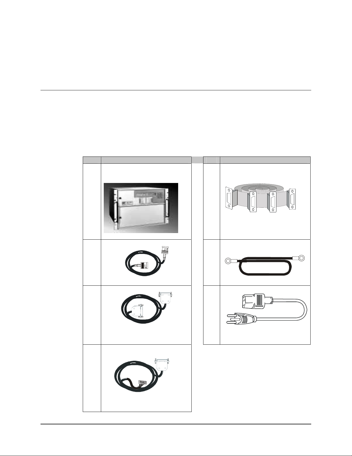
SMS-458B Modem Protection Switch Revision 2
Cable Configuration MN/SMS458B.IOM
A.1.1 Equipment Inspection
A.1.1.1 Included Parts
Refer to Table A-1 for equipment need to cable the SMS-458B switch.
Note: Parts are not illustrated to scale.
Table A-1. Equipment List
Qty Description Qty Description
1 SMS-458B Modem Protection
Switch
1 CA/0755 Cable Assy
AR CA/0813-4 Cable Assy, BNC
AR CA/6697-1 Cable Assy 50-P in
For ECL/HSSI Interface
AR CA/7706-1. Cable Assy, 9 to 50-Pin
For G.703 Interface
1 CA/0953 Cable , Ground Strap
2 WI/17250 Po wer Cord
A–2
Page 99

SMS-458B Modem Protection Switch Revision 2
Cable Configuration MN/SMS458B.IOM
A.2 SDM-2020 Modulator (TX only) with G.703 Data Interface
Perform the following installation procedures.
1. Install SMS-458B Modem Protection Switch in a rack. Secure the switch in
place.
2. Ensure cable assemblies are available for installation, refer to Figure A-1
Table A-2. Cable Assembly
QTY Part No. Nomenclature
1 CA/0755 Cable Assy, Control
5 CA/0813-4 Cable Assy, BNC
1 CA/0953 Ground Cable, Strap
5 CA/7706-1 Cable Assy, Interface (50-to-9-Pin)
2 WI/17250 Power Cord
3. Connect cable assemblies are specified in Table A-3.
Table A-3. Cable Connection
Cable Part No. SMS-458B SDM-2020M
CA/0755 Modem Control J3 Remote J1
CA/0813-4 Prime Mod Inputs J18 through J21 CP1 TX-IF
CA/0813-4 Backup Mod Input J26 CP1 TX-IF
CA/0953 Ground J39
CA/7706-1 Prime Modem J6 J5 AUX
CA/7705-1 Backup Modem J3 J5 AUX
WI/17250 Power Input J27 and J38
CA/0813-4 Prime TX Data G.703 DATA OUT J4
CA/0813-4 Backup TX Data G.703 DATA OUT J4
A–3
Page 100

SMS-458B Modem Protection Switch Revision 2
1
Cable Configuration MN/SMS458B.IOM
J39 J26
CP 1 TX-IFJ1 REMOTE
IN
J3 G.703
OUT
J4 G.703
J5 AUX
J1 J2 J3
J3 J4 J6
BACKUP
PRIME and BKUP SDM-2020M (X5)
J3 Tx Data
J4 Rx Data
J26 (1) BKUP Modulator Input
J3 EIA-485 Modem Control
J18 (1) PRIM Modulator Input
J19 (2) PRIM Modulator Input
J20 (3) PRIM Modulator Input
J39 GND ERDE
J21 (4) PRIM Modulator Input
SMS-458 Switch
PRIME1-4 and
BKUP (J1)
PRIME1 (CP1)
BKUP (CP1)
PRIME2 (CP1)
PRIME3 (CP1)
PRIME4 (CP1)
J6 Prime Modem
AS/2068 (A)
PRIME1 (J3)
PRIME1 (J4)
PRIME1 (J5)
J2 FAULT
(A) (B) (C) (D)
J2 J18 J19 J20 J21
J3 Tx Data
J4 Rx Data
J5 Terr Data
J6 Prime Modem
AS/2068 (B)
From
Customer
PRIME2 (J3)
PRIME2 (J4)
PRIME2 (J5)
J3 Tx Data
J5 Terr Data
AS/2068 (C)
From
Customer
PRIME3 (J3)
J5 Terr Data
J4 Rx Data
J6 Prime Modem
J3 Tx Data
J4 Rx Data
J6 Prime Modem
J5 Terr Data
AS/2068 (D)
From
Customer
PRIME3 (J4)
PRIME3 (J5)
From
PRIME4 (J3)
Customer
PRIME4 (J4)
PRIME4 (J5)
J3 J4 J6 J3 J4 J6 J3 J4 J6
J1 Tx Data
J2 Rx Data
J3 Back-Up Modem
---------------------
BkUp Modem
BKUP (J3)
BKUP (J4)
BKUP (J5)
CA/TBD
CA/0755
CA/0813-4
PRIME
SMS-458 (J3)
AS/2086 A (J3)
Remote J1
G.703 In J3
SMS-458 (J18)
AS/2086 A (J4)
AS/2086 A (J6)
Aux J5
Tx-IF CP1
G.703 Out J4
SMS-458 (J3)
PRIME 2
Remote J1
SMS-458 (J19)
AS/2086 B (J3)
AS/2086 B (J4)
AS/2086 B (J6)
Aux J5
Tx-IF CP1
G.703 In J3
G.703 Out J4
PRIME 3
SMS-458 (J3)
AS/2086 C (J3)
AS/2086 C (J4)
Remote J1
G.703 In J3
G.703 Out J4
SMS-458 (J20)
AS/2086 C (J6)
Aux J5
Tx-IF CP1
PRIME 4
SMS-458 (J3)
AS/2086 D (J3)
AS/2086 D (J4)
Remote J1
G.703 In J3
G.703 Out J4
SMS-458 (J21)
AS/2086 D (J6)
Aux J5
Tx-IF CP1
SMS-458 (J3)
BKUP
Remote J1
SMS-458 (J26)
BkUp (J1)
BkUp (J2)
BkUp (J3)
Aux J5
Tx-IF CP1
G.703 In J3
G.703 Out J4
From Customer’s Equipment
Figure A-1. SMS-458B Installation Diagram for SDM-2020 Modulator (TX Only) with
G.703 Data Interface
A–4
 Loading...