

Page 1

SMS-451
Satellite Switch
Model A, E, and T
Installation and Operation Manual
Part Number MN/SMS451. IOM Revision 0
This document supersedes the following documents:
SMS-451A, MN/SMS451A.IOM, Rev. 1 dated 4 August 1995
IMPORTANT
SMS-451E, MN/SMS451E.IOM, Rev. 1 dated 4 June 2001
SMS-451T, MN/SMS451T.IOM, Rev. 1 dated 24 August 1995
Page 2

Page 3

SMS-451
Comtech EF Data is an ISO 9001
Registered Company.
Satellite Switch
Model A, E, and T
Installation and Operation Manual
Part Number MN/SMS451.IOM
Revision 0
May 1, 2003
Page 4

Customer Support
Contact the Comtech EF Data Customer Support Department for:
• Product support
• Information on returning/upgrading a product
• Product training
• Reporting comments or suggestions concerning manuals
An Comtech EF Data Customer Support representative may be reached at:
Comtech EF Data
Attention: Customer Support Department
2114 West 7th Street
Tempe, Arizona 85281 USA
480.333.2200 (Main Comtech EF Data Number)
480.333.2161 (Main FAX Number)
480.333.2540 (Marketing FAX Number)
or, E-Mail can be sent to the Customer Support Department at:
service@comtechefdata.com
or, contact Customer Support Department at the web site:
www.comtechefdata.com
To return an Comtech EF Data product (in-warranty and out-of-warranty) for repair or
replacement:
1. Request a Return Material Authorization (RMA) number from the Comtech EF
Data Customer Support Department. Be prepared to supply the Customer
Support representative with the model number, serial number, and a description
of the problem.
2. To ensure that the product is not damaged during shipping, pack the product in
its original shipping carton/packaging.
3. Ship the product back to Comtech EF Data. (Shipping charges should be
prepaid.)
For more information regarding the warranty policies, refer to the disclaimer page located
behind the title page.
ii
Page 5

Table of Contents
CHAPTER 1. INTRODUCTION.................................................................................. 1–1
1.1 Description....................................................................................................................................................1–1
1.1.1 SMS-451A Description ..........................................................................................................................1–1
1.1.2 SMS-451E Description...........................................................................................................................1–5
1.1.3 SMS-451T Description...........................................................................................................................1–8
1.2 Specifications ..............................................................................................................................................1–10
1.2.1 SMS-451A Specifications.....................................................................................................................1–10
1.2.2 SMS-451E Specifications.....................................................................................................................1–11
1.2.3 SMS-451T Specifications.....................................................................................................................1–12
CHAPTER 2. INSTALLATION................................................................................... 2–1
2.1 Unpacking ..................................................................................................................................................... 2–1
2.2 System Installation....................................................................................................................................... 2–2
2.2.1 SMS-451A Installation ...........................................................................................................................2–2
2.2.2 SMS-451E Installation............................................................................................................................2–4
2.2.3 SMS-451T Installation............................................................................................................................2–5
2.3 External Connections................................................................................................................................... 2–6
2.3.1 SMS-451A External Connections...........................................................................................................2–6
2.3.1.1 Remote Interface (J5) ......................................................................................................................2–7
2.3.1.2 Modem Fault A and B (J8, J9) ........................................................................................................2–8
2.3.1.3 Receive IF Connectors (J19, J20, J21) ............................................................................................2–8
2.3.1.4 Transmit IF Connectors (J11, J13, J18)...........................................................................................2–8
2.3.1.5 Receive Data (J10, J12, J15) ...........................................................................................................2–9
2.3.1.6 Transmit Data (J1, J3, J6)................................................................................................................2–9
2.3.1.7 Transmit Clock (J2, J4, J7).............................................................................................................. 2–9
2.3.1.8 AC Power (J34, J24) .......................................................................................................................2–9
2.3.1.9 Ground (J25, J26)............................................................................................................................2–9
2.3.2 SMS-451E External Connections .........................................................................................................2–10
2.3.2.1 ECL Baseband DATA I/O (A, Common, and B).......................................................................... 2–11
2.3.2.2 Remote Connector.........................................................................................................................2–13
2.3.2.3 Demodulator Inputs (B, RX IF, and A).........................................................................................2–14
2.3.2.4 Modulator IF Ouputs (B TX IF, and B) ........................................................................................2–14
2.3.2.5 Power Connections........................................................................................................................ 2–14
2.3.2.6 Ground (ERDE).............................................................................................................................2–14
iii
Page 6

SMS-451 Satellite Switch Revision 0
Preface MN/SMS451.IOM
2.3.3 SMS-45T External Connections ...........................................................................................................2–15
2.3.3.1 ESC "A" Connector Pin Assignments (J16 and J26) ....................................................................2–16
2.3.3.2 ESC "B" Connector Pin Assignments (J17 and 27) ......................................................................2–17
2.3.3.3 ESC "COMMON" Connector Pin Assignemnt (J18 and J28).......................................................2–18
2.3.3.4 Remote Interface OUT (J5 and J25)..............................................................................................2–19
2.3.3.5 AC Power (J2 and J24)..................................................................................................................2–19
2.3.3.6 Ground (J3) ...................................................................................................................................2–19
CHAPTER 3. OPERATION........................................................................................ 3–1
3.1 Overview .......................................................................................................................................................3–1
3.2 SMS-451A/E Front Panel ............................................................................................................................3–2
3.2.1 SMS-451A/E Front Panel Indicators ......................................................................................................3–2
3.2.2 SMS-451A/E Front Panel Switches........................................................................................................3–2
3.3 SMS-451A/E Local Control.........................................................................................................................3–3
3.3.1 SMS-451A/E Modulator Operation........................................................................................................ 3–3
3.3.2 SMS-4512A/E Demodulator Operation..................................................................................................3–4
3.4 SMS-451A/E Remote Operation.................................................................................................................3–4
3.5 SMS-451T Front Panel ................................................................................................................................3–5
3.5.1 SMS-451T ESC "1"................................................................................................................................3–5
APPENDIX A B-141-1 BREAKOUT PANEL .............................................................A–1
A.1 Overview .....................................................................................................................................................A–1
A.2 External Connections................................................................................................................................. A–3
A.2.1 ESC-1 Interface J1 ................................................................................................................................ A–3
A.2.2 8 kbps RS-422 Interface (P2)................................................................................................................ A–5
A.2.3 Alarm Outputs (TB1)............................................................................................................................A–5
A.2.4 Backward Alarm (TB2) .........................................................................................................................A-6
A.2.5 ADPCM Audio Connector (TB3)......................................................................................................... A–6
INDEX .......................................................................................................................... I–1
iv
Page 7

SMS-451 Satellite Switch Revision 0
Preface MN/SMS451.IOM
Figures
Figure 1-1. SMS-451A ............................................................................................................................................ 1–1
Figure 1-2. SMS-451A System Block Diagram.......................................................................................................1–3
Figure 1-3. SMS-451A Switch Block Diagram........................................................................................................1–4
Figure 1-4. SMS-451E ............................................................................................................................................1–5
Figure 1-5. SMS-451E System Block Diagram .......................................................................................................1–6
Figure 1-6. SMS-451 Block Diagram with SDM-2020 Modulator and Demodulator with a HSSI Interface .......1–7
Figure 1-7. SMS-451T .............................................................................................................................................1–8
Figure 1-8. SMS-451T System Block Diagram .......................................................................................................1–9
Figure 2-1. Interconnect Diagram with EB-450 Buffers..........................................................................................2–2
Figure 2-2. SMS-451A Rear Panel View .................................................................................................................2–6
Figure 2-3. SMS-451E Rear Panel View................................................................................................................2–10
Figure 2-4. SMS-451T Front Panel View ..............................................................................................................2–15
Figure 3-1. SMS-451A Front Panel View................................................................................................................3–2
Figure 3-1A. SMS-451E Front Panel View............................................................................................................. 3-2
Figure 3-2. SMS-451T Front Panel View ................................................................................................................3–5
Figure A-1. B-141-1 Interface Breakout Panel .......................................................................................................A–1
Figure A-2. B-141-1 Interface Breakout Panel Schematic Diagram....................................................................... A–4
Tables
Table 1-1. SMS-451A Specifications.....................................................................................................................1–10
Table 1-2. SMS-451E Specifications .....................................................................................................................1–11
Table 1-3. SMS-451T Specifications .....................................................................................................................1–12
Table 2-1. SMS-451A Rear Panel Connectors......................................................................................................... 2–6
Table 2-2. SMS-451E Rear Panel Connectors .......................................................................................................2–10
Table 2-3. SMS-451T Rear Panel Connectors .......................................................................................................2–15
Table A-1. B-141-1 Breakout Panel Connectors.....................................................................................................A–2
v
Page 8
About this Manual
This manual describes the installation and operation information for the Comtech EF
Data:
• SMS-451A 1:1 Satellite Modem Switch
• SMS-451E 1:1 ECL Modem Protection Switch
• SMS-451T 1:1 ESC ESC Protection Switch
This is a technical document intended for earth station engineers, and operators
responsible for the operation and maintenance of the switch.
Conventions Used in this Manual
Preface
Cautions, Warning, and Important Notes
CAUTION indicates a hazardous situation that, if not avoided, may result in
minor or moderate injury. CAUTION may also be used to indicate other
CAUTION
WARN ING
IMPORTANT
unsafe practices or risks of property damage.
WARNING indicates a potentially hazardous situation that, if not avoided,
could result in death or serious injury.
IMPORTANT indicates a statement that is associated with the task
being performed.
Page 9

SMS-451 Satellite Switch Revision 0
Preface MN/SMS451.IOM
Metric Conversion
Metric conversion information is located on the inside back cover of this manual. This
information will assist the operator in cross-referencing English to Metric conversion.
Trademarks
Product names mentioned in this manual may be trademarks or registered trademarks of
their respective companies and are hereby acknowledged.
Related Documents
The following documents are referenced in this manual:
vii
Page 10

SMS-451 Satellite Switch Revision 0
Preface MN/SMS451.IOM
ELECTRICAL SAFETY
The SMS-451 Satellite Switch has been shown to comply with the following safety standard:
• EN 60950: Safety of Information Technology Equipment, including electrical business
machines.
The equipment is rated for operation over the range 85 to 264 volts AC. It has a maximum
power consumption of 60 watts.
FUSES
The SMS-451 Satellite Switch is fitted with two fuses, one each for line and neutral connections.
These are contained within the body of the IEC power connector, behind a small plastic flap.
• For 230 volt AC operation, use T0.75A, 20mm fuses.
• For 115 volt AC operation, use T1.25A fuses, 20mm fuses.
IMPORTANT
Environmental
The SMS-451 Satellite Switch must not be operated in an environment where the unit is
exposed to extremes of temperature outside the ambient range 0 to 50°C (32 to 122°F),
precipitation, condensation, or humid atmospheres above 95% RH, altitudes (unpressurized) greater than 2000 meters, excessive dust or vibration, flammable gases,
corrosive or explosive atmospheres.
Operation in vehicles or other transportable installations that are equipped to provide a
stable environment is permitted. If such vehicles do not provide a stable environment,
safety of the equipment to EN60950 may not be guaranteed.
For continued operator safety, always replace the fuses with the
correct type and rating.
viii
Page 11
SMS-451 Satellite Switch Revision 0
Preface MN/SMS451.IOM
Installation
The installation and connection to the line supply must be made in compliance to local or
national wiring codes and regulations.
The SMS-451 Satellite Switch is designed for connection to a power system that has
separate ground, line and neutral conductors. The equipment is not designed for
connection to power system that has no direct connection to ground.
The SMS-451 Satellite Switch is shipped with a line inlet cable suitable for use in the
country of operation. If it is necessary to replace this cable, ensure the replacement has an
equivalent specification. Examples of acceptable ratings for the cable include HAR,
BASEC and HOXXX-X. Examples of acceptable connector ratings include VDE, NFUSE, UL, CSA, OVE, CEBEC, NEMKO, DEMKO, BS1636A, BSI, SETI, IMQ,
KEMA-KEUR and SEV.
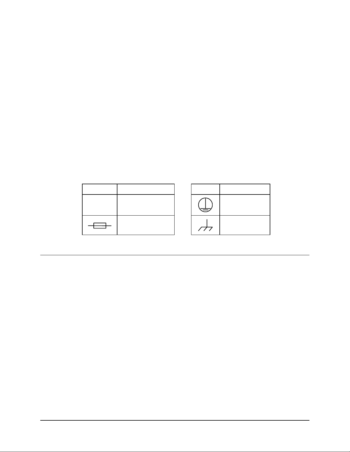
International Symbols:
Symbol Definition Symbol Definition
~
Alternating Current
Fuse
Telecommunications Terminal Equipment Directive
In accordance with the Telecommunications Terminal Equipment Directive 91/263/EEC,
this equipment should not be directly connected to the Public Telecommunications
Network.
Protective Earth
Chassis Ground
ix
Page 12

SMS-451 Satellite Switch Revision 0
Preface MN/SMS451.IOM
EMC (Electromagnetic Compatibility)
In accordance with European Directive 89/336/EEC, the SMS-451 Satellite Switch has
been shown, by independent testing, to comply with the following standards:
Emissions: EN 55022 Class B - Limits and methods of measurement of radio
interference characteristics of Information Technology Equipment.
(Also tested to FCC Part 15 Class B)
Immunity: EN 50082 Part 1 - Generic immunity standard, Part 1: Domestic,
commercial and light industrial environment.
Additionally, the SDM-2020D has been shown to comply with the following standards:
EN 61000-3-2 Harmonic Currents Emission
EN 61000-3-3 Voltage Fluctuations and Flicker
EN 61000-4-2 ESD Immunity
EN 61000-4-4 EFT Burst Immunity
EN 61000-4-5 Surge Immunity
EN 61000-4-6 RF Conducted Immunity
EN 61000-4-8 Power frequency Magnetic Field Immunity
EN 61000-4-9 Pulse Magnetic Field Immunity
EN 61000-4-11 Voltage Dips, Interruptions, and Variations Immunity
EN 61000-4-13 Immunity to Harmonics
In order that the Modem continues to comply with these standards,
observe the following instructions:
IMPORTANT
• Connections to the transmit and receive IF ports (Type N and Type F, female,
connectors) should be made using a good quality coaxial cable - for example
RG58/U (50Ω or RG59/U (75Ω).
• All 'D' type connectors attached to the rear panel must have back-shells that
provide continuous metallic shielding. Cable with a continuous outer shield
(either foil or braid, or both) must be used, and the shield must be bonded to the
back shell.
• The equipment must be operated with its cover on at all times. If it becomes
necessary to remove the cover, the user should ensure that the cover is correctly
re-fitted before normal operation commences.
x
Page 13

SMS-451 Satellite Switch Revision 0
Preface MN/SMS451.IOM
Warranty Policy
This Comtech EF Data product is warranted against defects in material and workmanship
for a period of one year from the date of shipment. During the warranty period, Comtech
EF Data will, at its option, repair or replace products that prove to be defective.
For equipment under warranty, the customer is responsible for freight to Comtech EF
Data and all related custom, taxes, tariffs, insurance, etc. Comtech EF Data is responsible
for the freight charges only for return of the equipment from the factory to the customer.
Comtech EF Data will return the equipment by the same method (i.e., Air, Express,
Surface) as the equipment was sent to Comtech EF Data.
Limitations of Warranty
The foregoing warranty shall not apply to defects resulting from improper installation or
maintenance, abuse, unauthorized modification, or operation outside of environmental
specifications for the product, or, for damages that occur due to improper repackaging of
equipment for return to Comtech EF Data.
No other warranty is expressed or implied. Comtech EF Data specifically disclaims the
implied warranties of merchantability and fitness for particular purpose.
Exclusive Remedies
The remedies provided herein are the buyer's sole and exclusive remedies. Comtech EF
Data shall not be liable for any direct, indirect, special, incidental, or consequential
damages, whether based on contract, tort, or any other legal theory.
Disclaimer
Comtech EF Data has reviewed this manual thoroughly in order that it will be an easy-touse guide to your equipment. All statements, technical information, and recommendations
in this manual and in any guides or related documents are believed reliable, but the
accuracy and completeness thereof are not guaranteed or warranted, and they are not
intended to be, nor should they be understood to be, representations or warranties
concerning the products described. Further, Comtech EF Data reserves the right to make
changes in the specifications of the products described in this manual at any time without
notice and without obligation to notify any person of such changes.
If you have any questions regarding your equipment or the information in this manual,
please contact the Comtech EF Data Customer Support Department.
xi
Page 14

SMS-451 Satellite Switch Revision 0
Preface MN/SMS451.IOM
This page is intentionally left blank.
xii
Page 15

Chapter 1. INTRODUCTION
A
A
This manual describes the SMS-451 Satellite Switch (Model A, E, or T), referred to in
this document as “the switch.”
1.1 Description
The following descriptions are referenced to the applicable switch.
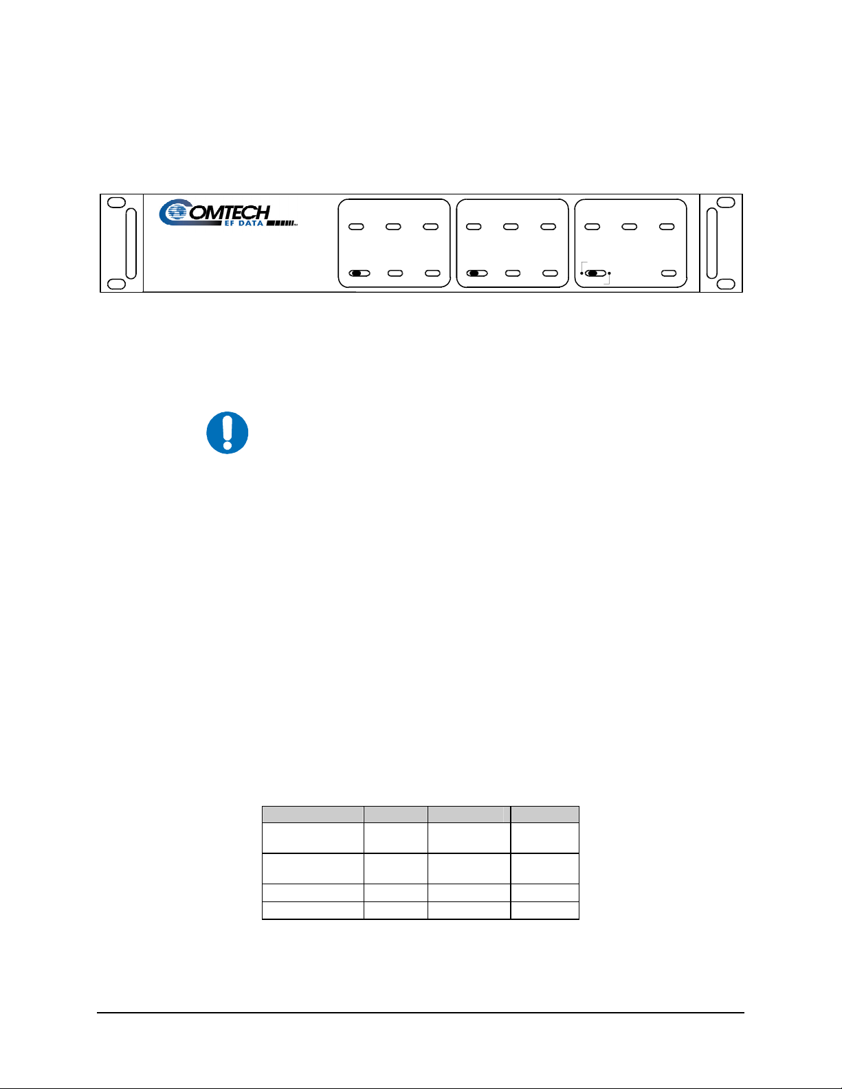
1.1.1 SMS-451A Description
SMS-451A
SATELLITE MODEM SWITCH
M ODULATOR
MANUAL ON-LI NE FAULT
ABB
A
UTO
DEM ODULATOR
MANUAL ON-LI NE FAULT
A
UTO
B
ABB
AA
S W I T C H S T A T U S
RE M O T E L O C A L P W R 1
R E M
B
L O C
P W R 2
Figure 1-1. SMS-451A
The SMS-451A 1:1 Satellite Modem Switch (Figure 1-1 ) is a fully-automated 1:1
satellite modem (protection) switch for the following Comtech EF Data modems:
• SDM-450
• SDM-9000 with the G.703 interface.
The switch provides redundancy for one prime modem with one backup modem.
1–1
Page 16

SMS-451 Sateliite Switch Revision 0
Introduction MN/SMS451.IOM
The switch contains:
• Circuitry for the data
• IF switching
• Remote and local status reporting
• Remote and local control
A 50
Ω system consists of the following assemblies:
Switch Top Assembly
1:1 Switch Modem PCB
Chassis Assembly
Front Panel Assembly
Power Supply
Cable Assembly (75Ω)
Cable Assembly (75Ω)
Cable Assembly, DC Power
AS/1781-1
AS/1760-1
AS/1780
AS/1090
PS/AC40W03P02
CA/1798B
CA/1799B
CA/1772B
A 75
Ω system consists of the following assemblies:
Switch Top Assembly
1:1 Switch Modem PCB
Chassis Assembly
Front Panel Assembly
Power Supply
Cable Assembly (50Ω)
Cable Assembly (75Ω)
Cable Assembly (75Ω)
Cable Assembly, DC Power
AS/1781-2
AS/1760-2
AS/1780
AS/1090
PS/AC40W03P02
CA/1800B
CA/1799B
CA/1798B
CA/1772B
Additional versions of the SMS-451 also support the SDM-2020 Modulator and
demodulator:
• SDM-2020 with G.703 Interface
• SDM-2020 with ASI Interface
IMPORTANT
The 70/140 MHZ and L-Band versions of the SMS-451 are available to
support the SDM-2020 Demodulator. The TX IF of the SMS-451 is
alaways 70/140 MHz.
1–2
Page 17

SMS-451 Sateliite Switch Revision 0
A
A
XDTA
XDTA
A
A
X
X
R
A
R
R
XDTARX
X
XDTA
A
X
R
Introduction MN/SMS451.IOM
The system block diagram (Figure 1-2) shows how the switch provides the interface
between the prime modem, the terminal, and the customer equipment.
B-141-1
BREAKOUT PANEL
TX DA T
RX IF
TX CL OCK J4
CA/2674
REMOTE
CA/037-8
INTERFACE
J28
SMS451T
J3
J20
REMOTE INTERF ACE
J5
J25
J26
ESC 2
CA/0737- 4
J27
ESC 2
B
J1
J19
J7
J2
CA/0813-8J6
75 OHM - BNC
50 OHM - BNC
CP2J21
CA/0813-8
J12
J11
J14 TX
EXT
CLK
ESC
TER
SMS-451A
SDM-450
RX RF
J9 J10 J12 J11
J10J5J13 J8
R
RX
CLKTXCLK
ESC-450
FRAMING
SWITCH
T
FAULT
TX RF
TWI NA
CABLES
TER
CA/2590
LM J4
FAULT
J14
CP1
*
J9R
UNIT
75 OHM - BNC
50 OHM - BNC
CA/0813-8
CA/0737-4
CA/0813-8
CP2
J12
J14
EXT
CLK
J11
ESC
TX
TER
SDM-450
RX RF
J9 J10 J12 J11
J10 J5 J13 J8
R
CLK
ESC-450
FRAMING
UNIT
TX RF
SWITCH
FAULT
TWI NAX
CABLES
T
TER
LM J4
CP1
75 OHM - BNC
50 OHM - BNC
J14
*
J9R
B
T
CLK
Figure 1-2. System Block Diagram
J9 J8
CA/2590
FAULT
B
CA/0813-8
CA/0813-8
75 OHM - BNC
50 OHM - BNC
J15
J10
J18
J11
J12
RX DA TA
J13
TX IF
1–3
Page 18
SMS-451 Sateliite Switch Revision 0
Introduction MN/SMS451.IOM
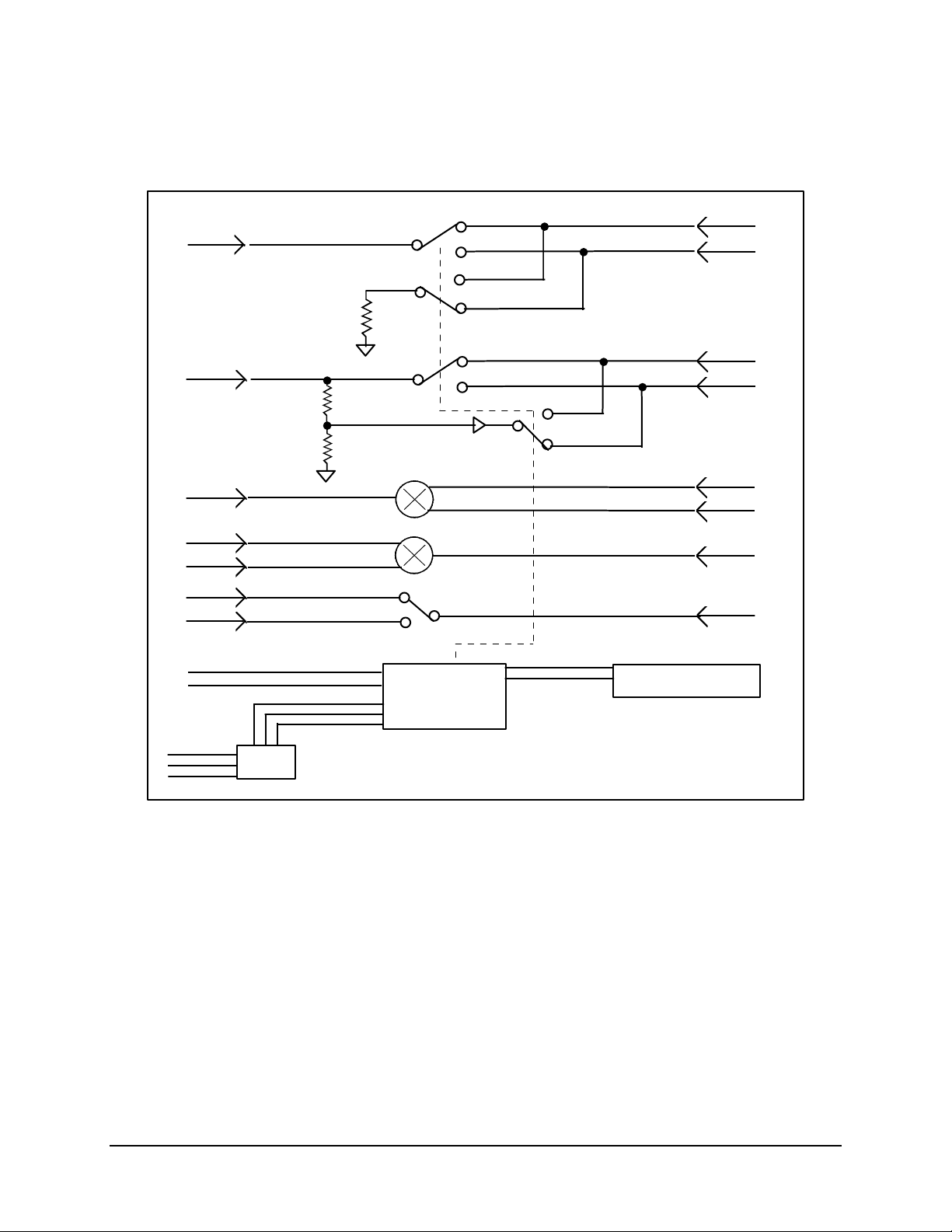
A block diagram of the switch is shown in Figure 1-3.
TX IF A
TX IF
COM
TX DATA
COM
TX IF A
TX DATA A
TX DATA B
TX CLOCK
COM
RX IF A
RX IF B
RX DATA A
RX DATA B
REMOTE
ALARMS
MOD FAULT
DMD FAULT
COM FAULT
FAULT
RELAYS
CONTROL
FRONT PANEL
LOGIC
Figure 1-3. SMS-451A Switch Block Diagram
TX CLOCK A
TX CLOCK B
RX IF COM
RX DATA COM
1–4
Page 19
SMS-451 Sateliite Switch Revision 0
Introduction MN/SMS451.IOM
1.1.2 SMS-451E Description
SMS-451E ECL MODEM
PROTECTION SWITCH
The SMS-451E 1:1 ECL Modem Protection Switch (Figure 1-4) is a fully automated 1:1
ECL protection switch for the Comtech EF Data SDM-9000 satellite modem.
IMPORTANT
The switch is used to protect SDM-9000 modems using an ECL, Positive Emitter
Coupled Logic (PECL), or MIL-STD-188 terrestrial interface. The switch provides
redundancy for one prime modem with one backup modem.
The switch contains circuitry for:
• Data and IF switching
• Remote and local status reporting
• Remote and local control
The switch can be supplied with any of the following baseband interfaces:
• ECL
• PECL (positive level ECL)
• MIL-STD-188
The switch top assembly has the following configurations:
MODULATOR
MANUAL
ON-LINE FAULT
A
AUTO
A
B
B
MANUAL
A
A
B
DEMODULATOR
ON-LINE FAULT
AUTO
B
SWITCH ST ATUS
REM O T E
A
A
B
B
L O C A L P W R 1
R E M
L O C
Figure 1-4. SMS-451E
ECL/HSSI connection also is available for the SDM-2020 Modems.
Operation Input Frequency Interface
Modem
(Dependent)
Mod/Demod
(Independent)
AC 75Ω
AC 50Ω
DC 50Ω
DC 75Ω
70 ECL
140 PECL
188
P W R 2
1–5
Page 20

SMS-451 Sateliite Switch Revision 0
Introduction MN/SMS451.IOM
The system block diagram (Figure 1-5) shows how the switch provides the interface
between the prime modem and the terminal and IF converter equipment.
SMS-451E
RX IF
TX TER
TX DATA
TX CLOCK
TX SYNC
ESC
2 AUDIO
4 BW ALARM
RX IF
SDM-9000
ECL INTERFACE
TX TER
ESC
RX IF
SDM-9000
ECL INTERFACE
TX TER
ESC
TX IF
RX TER
FAULT
TX IF
RX TER
FAULT
TX IF
RX TER
RX DATA
RX CLOCK
RX SYNC
Figure 1-5. SMS-451E Block Diagram with SDM-9000 Satellite Modem
Connection of the SMS-451E with the SDM-2020 Modulator and/or Demodulator with a
HSSI Interface along with a Cisco router and test translator is shown in Figure 1-6. The
Y-cables between the modem and switch are provided. The cable between the switch and
the router is ordered separately.
1–6
Page 21

SMS-451 Sateliite Switch Revision 0
Introduction MN/SMS451.IOM
Cable,
ECL (Switch) To
HSSI (Router)
PL/6697-1(Standard)
-1 = 4 ft (1.2 meter)
-2 = 6 ft (1.8 meter)
-3 = 8 ft (2.4 meter)
DTE
Cisco
Router
CA
TA
x = No Connection
ST
TT
SD
RT
RD
DCE
SMS451E
Data
Section
Of
Switch
DTE
DTE
Y-Cable, PL/7126-1
DCE
ST
TT
SD
CA
x
RT
RD
Demodulator
CA
x
DCE
ST
TT
SD
CA
x
RT
RD
Demodulator
CA
x
DCE
Y-Cable
SDM-2020
Modulator
SDM-2020
SDM-2020
Modulator
SDM-2020
Tx
IF
Tx
IF
Rx
IF
SMS-
451E
IF
Section
Tx
IF
Rx
IF
Of
Switch
Rx
IF
70 MHz
IF
Loop
Test
Translator
(L-Band)
L-Band
or
70/170
IF
Figure 1-6. SMS-451 Block Diagram with SDM-2020 Modulator and Demodulator with a
HSSI Interface
1–7
Page 22

SMS-451 Sateliite Switch Revision 0
Introduction MN/SMS451.IOM
1.1.3 SMS-451T Description
Note: The SMS-451T 1:1 ESC Protection Switch can only be used in conjunction with an
SMS-451A switch. All controls for the switch are provided by the SMS-451A Switch.
SWITCH STATUS
PWR1 P WR2
ESC 1
PWR1
PWR2
ESC 2
Figure 1-7. SMS-451T
The switch (Figure 1-7) adds 1:1 ESC switching capability to the SMS-451A 1:1 satellite
modem switch. The ESC channel is compatible with the optional ESC channels used on
the ESC-450 framing unit.
The switch also provides redundancy for the ESC channel of the prime framing unit with
the ESC channel of one backup framing unit.
A system consists of the following assemblies:
Switch Top Assembly
ESC 1 PCB
ESC 2 PCB
Chassis Assembly
Front Panel Assembly
Power Supply
AS/1941
AS/1862
AS/1863
AS/1942
AS/1855-1
PS/AC40W03P02
A block diagram of the switch is shown in Figure 1-8.
1–8
Page 23

SMS-451 Sateliite Switch Revision 0
Introduction MN/SMS451.IOM
J4
J6
J5
J8
J7
J9
J6
J10
50
50
50
50
50
50
25
25
REMOTE
SMS-451T
LOGIC CONTR OL
POWER
SUPPLY
LOGIC/
CONTROL
RELAY
DRIVERS
2
POWER
SUPPLY
Figure 1-8. SMS-451T Block Diagram
1–9
Page 24

SMS-451 Sateliite Switch Revision 0
Introduction MN/SMS451.IOM
1.2 Specifications
The following specifications are referenced to the applicable switch.
1.2.1 SMS-451A Specifications
The interface operates to the specifications described in Table 1-1.
Table 1-1. SMS-451A Specifications
General Specifications
Interface:
IF
Baseband Data
TX Clock
Controls:
Modulator
Demodulator
Common
Indicators:
Modulator
Demodulator
Common
Remote Control Via external contact closures on a 25-pin female D connector for
Physical Specifications
Operating Temperature
Power 90 to 264 VAC
Size 19 W x 18 D x 3.5 H inches (48.26 H x 45.72 D x 8.89 cm)
Weight 10 lbs (4.5 kg)
Humidity 0 to 90% Noncondensing
75Ω BNC (50Ω optional)
75Ω BNC (50Ω optional)
75Ω BNC (50Ω optional)
A or B online select
Auto
A or B online select
Auto
Remote or Local
A or B online
A and B faults
A and B online
A and B faults
Power supply 1 and 2 On
Remote control activated
A/B modulator select and A/B demodulator select.
0 to 40°C (32 to 104°F)
47 to 63 Hz
10W maximum
1–10
Page 25

SMS-451 Sateliite Switch Revision 0
Introduction MN/SMS451.IOM
1.2.2 SMS-451E Specifications
The interface operates to the specifications described in Table 1-2.
Table 1-2. SMS-451E Specifications
General Specifications
Interface:
Digital
IF
Controls:
Modulator
Demodulator
Common
Indicators:
Modulator
Demodulator
Common
Remote Control Via external contact closure on a 25-pin female D connector for
Physical Specifications
Power 90 to 260 VAC.
Size 19 W x 18 D x 3.5 H inches (48.26 W x 45.72 D x 8.89 H cm)
Weight 10 lbs (4.5 kg)
ECL, PECL, MIL-STD-188 50-pin D.
75Ω BNC (50Ω optional).
A or B online select.
Auto.
A or B online select.
Auto.
Remote or local.
A or B online.
A and/or B fault.
A or B online.
A and/or B fault.
Power supply 1 and/or 2 ON.
Remote control activated.
A/B modulator select and A/B demodulator select.
47 to 63 Hz.
10W max.
-48 VDC optional.
1–11
Page 26

SMS-451 Sateliite Switch Revision 0
Introduction MN/SMS451.IOM
1.2.3 SMS-451T Specifications
The interface operates to the specifications described in Table 1-3.
Table 1-3. SMS-451T Specifications
General Specifications
ESC Interface Engineering Service Channels.
50-pin D female.
Remote Control
Interface
Indicators Power Supply 1 and 2 On each for ESC 1 and ESC 2.
Physical Specifications
Power 90 to 264 VAC
Size 19 W x 18 D x 3.5 H inches (48.26 W x 45.72 D x 8.89 H cm)
Weight 10 lbs (4.5 kg)
Via external contact closures on a 25-pin female D connector.
47 to 63 Hz
10W max.
1–12
Page 27

Chapter 2. INSTALLATION
This chapter provides system installation and external connection information.
2.1 Unpacking
The switch and manual are packaged in pre-formed reusable foam inside a cardboard
carton.
To remove the switch:
Do not use any cutting tool that will extend more than 1 inch into the
container and cause damage to the switch.
CAUTION
1. Cut the tape at the top of the carton where it is indicated OPEN THIS END.
2. Lift off the foam covering the switch.
3. Remove the switch, manual, and power cords from carton.
4. Save the packing material for reshipment either back to the factory or to another
site.
5. Inspect the equipment for damage incurred during shipment.
6. Check the equipment against the packing list shipped with the equipment to
ensure that the shipment is complete.
7. Refer to Section 2.2 system installation instructions.
2-1
Page 28

SMS-451 Satellite Switch Revision 0
A
A
A
X
A
X
X
R
X
R
X
R
X
A
X
RTX
Installation MN/SMS451.IOM
2.2 System Installation
2.2.1 SMS-451A Installation
Install the switch as follows:
1. Mount the switch in a 19-inch (48 cm) rack with four screws between the two
modems.
Notes:
1. Refer to Chapter 1 for a block diagram with ESC-450 framing units.
2. Refer to Figure 2-1 for the interconnect diagram of a system with
EB-450 buffers.
RX IF
TX CL OCK
SMS-451A
CA/2590
J21
J19
J1
J7
J2
CA/0813-8J6
75 OHM - BNC
50 OHM - BNC
CP2
CA/0813-8
J12
EXT
CLK
RX RF
SDM-450
RX
DATA
CP3
J9
R
SAT
J3TX DA TA
J20
J4
EB-450-2
T
J6
TER
BUFFER
SDM-450
RX RF
75 OHM - BNC
50 OHM - BNC
CA/0813-8
CA/0813-8
CP2
J12
J14
EXT
CLK
T
TER
B
RX
DATA
CP3
J9
R
SAT
EB-450-2
BUFFER
J14
SWITCH
FAULT CA/0813-8
TX RF 50 OHM - BNC
CP1
TX
DATA
CP4
75 OHM BNC
J5
T
SAT
LM J4
J7R
TER
TX RF
CP1
J14
SWITCH
FAULT
TX
DATA
CP4
75 OHM BNC
J5
SAT
LM J4
J9R
TER
*
*
FAULT
CA/2590
J9 J8
FAULT
B
CA/0813-8
75 OHM - BNC
75 OHM - BNC
50 OHM - BNC
J15
J10
J18
J11
J12
RX DAT
J13
TX IF
Figure 2-1. Interconnect Diagram with EB-450 Buffers
2-2
Page 29

SMS-451 Satellite Switch Revision 0
Installation MN/SMS451.IOM
2. Connect the “RX IF COM” BNC connector on the rear panel to the customer
equipment RX IF input.
3. Connect the “A” BNC to the prime modem RX IF input (cable provided).
4. Connect the “B” BNC the backup modem RX IF input (cable provided).
5. Connect the “TX IF COM” BNC connector on the rear panel to the customer
equipment TX IF output.
6. Connect the “A” BNC to the prime modem TX IF output (cable provided).
7. Connect the “B” BNC the backup modem TX IF output (cable provided).
8. Connect the “RX DATA COM” BNC connector on the rear panel to the
customer equipment RX DATA input.
9. Connect the “A” BNC to the prime modem RX DATA IN (cable provided).
10. Connect the “B” BNC the backup modem RX DATA IN (cable provided).
11. Connect the “TX DATA COM” BNC connector on the rear panel to the
customer equipment TX DATA output.
12. Connect the “A” BNC to the prime modem TX DATA OUT (cable provided).
13. Connect the “B” BNC the backup modem TX DATA OUT (cable provided).
14. Connect the “MODEM FAULT A” 9-pin D connector on the rear panel to the
prime modem TTL fault connector.
15. Connect the “MODEM FAULT B” 9-pin D connector on the rear panel to the
backup modem TTL fault connector.
16. Connect the remote interface connector to the customer remote terminal.
17. Connect AC power to AC 1 and AC 2 with power cables that are provided.
If two AC power sources are available, connect AC 1 and the prime modem
to one AC source. Connect AC 2 and the backup modem to the other AC
IMPORTANT
source.
18. Refer to the appropriate installation and operation manual for installation
instructions for the prime and backup modems. The configurations of both
modems must be set the same.
19. If there is any problem installing the switch, call Comtech EF Data Customer
Support department for troubleshooting assistance.
2-3
Page 30

SMS-451 Satellite Switch Revision 0
Installation MN/SMS451.IOM
2.2.2 SMS-451E Installation
Install the switch as follows:
1. Using four screws, mount the switch in a 19-inch rack.
2. Connect the “TX IF” BNC connector on the switch rear panel to the
up converter.
3. Connect the “A” BNC to the prime modem TX IF Out (cable provided).
4. Connect the “B” BNC to the backup modem TX IF Out (cable provided).
5. Connect the data interface common 50-pin connector to the DTE equipment.
6. Connect the “A” baseband cables (BNCs or 50-pin connectors as in Step 5)
to the prime modem data connector (cables provided).
7. Connect the “B” baseband cables to the backup modem data connector
(cables provided).
8. Connect the “RX IF” BNC to the down converter.
9. Connect the “A” BNC to the prime modem RX IF IN.
10. Connect the “B” BNC to the backup modem RX IF IN.
11. Connect AC power to AC 1 (J11) and AC 2 (J12) with power cables that are
provided.
If two AC power sources are available, connect AC 1 and the prime modem
to one AC source. Connect AC 2 and the backup modem to the other AC
IMPORTANT
source.
12. Refer to the appropriate modem installation and operation manual for installation
instructions of the prime and backup modems. The configurations of both
modems must be set the same.
13. Connect the remote terminal to the Remote connector.
14. If there is any problem installing the switch, call Comtech EF Data Customer
Support for troubleshooting assistance.
2-4
Page 31

SMS-451 Satellite Switch Revision 0
Installation MN/SMS451.IOM
2.2.3 SMS-451T Installation
Install the switch as follows:
1. Mount the switch chassis in the assigned position in the equipment rack.
2. Connect the cables to the appropriate locations on the rear panel.
Notes:
1. Refer to Section 2.3 for connector pinouts, placement, and function.
2. Refer to Chapter 1 in the SMS-451A manual for a typical interconnect
diagram of the system.
3. Turn ON the power switches located on the rear panel.
4. If there is any problem during installation, contact Comtech EF Data Customer
Support department..
2-5
Page 32

SMS-451 Satellite Switch Revision 0
Installation MN/SMS451.IOM
2.3 External Connections
2.3.1 SMS-451A External Connections
Connections between the switch and other equipment are made through rear panel
connectors. The connectors are listed in Table 2-1and the locations are shown in
Figure 2-2.
Table 2-1. SMS-451A Rear Panel Connectors
Name Ref.
Connector Type Function
Desig.
REMOTE J5 25-pin D Remote Interface
Control/Status
FAULT J9
J8
IF IN A
IF IN COM
IF IN B
IF OUT A
IF OUT COM
IF OUT B
RX DATA A
RX DATA COM
RX DATA B
TX DATA A
TX DATA COM
TX DATA B
TX CLK A
TX CLK COM
TX CLK B
J21
J20
J22
J18
J13
J11
J15
J12
J10
J6
J3
J1
J7
J4
J2
9-pin D
9-pin D
BNC
BNC
BNC
BNC
BNC
BNC
BNC
BNC
BNC
BNC
BNC
BNC
BNC
BNC
BNC
Modem Fault A
Modem Fault B
Modem A Input
RX IF Input
Modem B Input
Modem A
TX IF Output
Modem B
Modem A
RX Data Com
Modem B
Modem A
TX Data Com
Modem B
Modem A
TX Clock Com
Modem B
AC POWER J23, J24 CEE22 AC Power Input
GND J25, J26 #10-32 STUD Ground
A
J 2 1
R X I F
C O M
J 2 0
B
J 1 9
A
J 1 8
T X I F
C O M
J 1 3
B
J 1 1
J15
A
RX D ATA
COM
J12
J10
B
A
J6
TX DATA
COM
J3
J1
B
T X CLOCK
A
C O M
J 7
J 4
B
J
2
J 2 5
G N D
E R D E
A C 1
J 2 3
A C 2
J 2 4
AC1
AC2 MODEM
FAULT A
J9 J8 J 5
MODEM
FAULT B
REMOTE INTERFACE
J26
GND
ERDE
Figure 2-2. SMS-451A Rear Panel View
2-6
Page 33

SMS-451 Satellite Switch Revision 0
Installation MN/SMS451.IOM
2.3.1.1 Remote Interface (J5)
The remote interface is provided on a 25-pin female D connector. The remote interface
connector provides remote control and online/offline status of the switch.
The Local/Remote switch on the front panel must be in the Remote mode in order to
control from this input. Status is available regardless of the position of the Local/Remote
switch. Screw locks are provided for mechanical security of the mating connector.
Signal Function Name Pin #
DEMOD SWITCH STATUS NO(B)
NC(A)
COM
MOD SWITCH STATUS NO(B)
NC(A)
COM
CONTROL MOD REMOTE MR(A)
MR(B)
GND
CONTROL DEMOD REMOTE DR(A)
DR(B)
GND
MODE STATUS COM 18
LOCAL NO 16
REMOTE NC 17
GROUND GND 24
NO CONNECTION --- 19, 20, 21,
Note: A closure between the “COM” and “NC” indicates that the “A” unit is online.
An external connection between “GND” and “MR(A)” will force the “A” modulator
online.
8
7
15
6
5
13
4
3
14
2
1
9
22, 23
2-7
Page 34

SMS-451 Satellite Switch Revision 0
Installation MN/SMS451.IOM
2.3.1.2 Modem Fault A and B (J8, J9)
The modem fault is provided on a 9-pin female D connector. Modem Fault A and B are
Transistor-Transistor Logic (TTL) inputs from the modem’s modulator and demodulator
TTL fault outputs.
Screw locks are provided for mechanical security on the mating connector.
Pin # Name Function
1 NC NO CONNECTION
2 NC NO CONNECTION
3 NC NO CONNECTION
4 MOD FLT MODULATOR FAULTED
5 GND MODULATOR GROUND
6 NC NO CONNECTION
7 DEM FLT DEMODULATOR FAULTED
8 GND DEMODULATOR GROUND
9 NC NO CONNECTION
2.3.1.3 Receive IF Connectors (J19, J20, J21)
These connectors are the RX IF splitter connectors. The RX IF of the prime modem
connects to RX IF A. The RX IF of the backup modem connects to RX IF B. RX IF
COM connects to the customer equipment. The characteristic impedance of these
connections is 75
Ω (50Ω optional) from 50 to 180 MHz.
There will be a 3 dB loss between A or B and the COM connector. If the backup or prime
modem is disconnected for any reason, place a 75
Ω or 50Ω termination on the unused
connector.
2.3.1.4 Transmit IF Connectors (J11, J13, J18)
The TX IF output of the prime modem connects to TX IF “A.” The TX IF output of the
backup modem connects to TX IF “B.” TX IF COM is the transmit IF output connector
and connects to the customer equipment. The TX IF output of the online modem will be
present at this connector. The characteristic impedance of these connections is 75
optional) from 50 to 180 MHz
Ω (50Ω
2-8
Page 35

SMS-451 Satellite Switch Revision 0
Installation MN/SMS451.IOM
2.3.1.5 Receive Data (J10, J12, J15)
The RX Data output of the prime modem connects to RX DATA “A.” The RX Data
output of the backup modem connects to RX DATA “B.” RX DATA COM is the data
output to the customer. The characteristic impedance of these connections is 75
50 to 180 MHz.
Ω from
2.3.1.6 Transmit Data (J1, J3, J6)
The TX Data input of the prime modem connects to TX DATA “A.” The TX Data input
of the backup modem connects to TX DATA “B.” TX DATA COM is the data input to
the customer. The characteristic impedance of these connections is 75
MHz. The offline unit will always have buffered data.
Ω from 50 to 180
2.3.1.7 Transmit Clock (J2, J4, J7)
The TX Clock input of the prime modem connects to TX CLOCK “A.” The TX Clock
input of the backup modem connects to TX CLOCK “B.” TX CLOCK COM is the clock
input to the customer. The characteristic impedance of these connections is 75
to 180 MHz. There will be a 3 dB loss between the COM and the “A” or “B” connector.
Ω from 50
2.3.1.8 AC Power (J34, J24)
The 90 to 264 AC power is supplied independently to each of the two power supplies by
a standard detachable, non-locking, 3-prong power cord. Maximum power consumption
is 10W. The input range is 90 to 264 VAC continuous and self-adjusting. The switch is
designed to operate on one power supply.
2.3.1.9 Ground (J25, J26)
There are two #10-32 studs available on the rear for the purpose of connecting a common
chassis ground between all of the equipment.
2-9
Page 36

SMS-451 Satellite Switch Revision 0
Installation MN/SMS451.IOM
2.3.2 SMS-451E External Connections
Connections between the switch and other equipment are made through rear panel
connectors. These connectors are listed in Table 2-2 and the locations are shown in
Figure 2-3.
Table 2-2. SMS-451E Rear Panel Connectors
Name Connector Type Function
DATA
INTERFACE
REMOTE 25-pin D Remote Control/
RX IF BNC RX IF Input
A BNC Demodulator A
B BNC Demodulator B
TX IF BNC TX IF Output
A BNC Modulator A
B BNC Modulator B
AC POWER CEE22 AC Power Input
Ground #10-32 STD Chassis Ground
50-pin D ECL Interface
Remote Status
DEMODULATOR
RX I F
B
A
Made in U. S.A.
REMOTE
LABEL HERE
B
DATA I NTERFACE
COMMON
Figure 2-3. SMS-451E Rear Panel View
B
MODULATOR
TX IF
A
GND
A
ERDE
2-10
Page 37

SMS-451 Satellite Switch Revision 0
Installation MN/SMS451.IOM
2.3.2.1 ECL Baseband DATA I/O (B, Common, and A)
The ECL interface is provided on a 50-pin female D connector. The switch DATA I/O
connectors provide the baseband data interface from the DTE equipment to the switch,
and from the switch to the prime and backup modems. Screw locks are provided for
mechanical security of the mating connector.
Signal Function Name Pin #
GROUND GND 1, 2
SEND DATA (SD) TXD-A (ECL-)
TXD-B (ECL+)
TERRESTRIAL TIMING (TT) TXO-A (ECL-)
TXO-B (ECL+) 4 5
SYNC TX FRAME (TX SYNC) SD-A (ECL-)
SD-B (ECL+)
EXTERNAL BUFFER CLOCK EXC-A (ECL-)
EXC-B (ECL+)
RECEIVE DATA (RD) RXD-A (ECL-)
RXD-B (ECL+)
RECEIVE TIMING (RT) RXC-A
RXC-B
SYNC RX FRAME (RX SYNC) RD-A
RD-B
SEND TIMING (ST) RXC-A
RXC-B
RECEIVE LINE SIGNAL DET RXO-A
RXO-B
ADPCM1 AUDIO IN A1I-A
A1I-B
ADPCM1 AUDIO OUT A1O-A
A1O-B
ADPCM2 AUDIO IN A2I-A
A2I-B
ADPCM2 AUDIO OUT A2O-A
A2O-B
BACKWARD ALARM 1 OUT BWO1-C
BWO1-NC
BWO1-NO
BACKWARD ALARM 2 OUT BWO2-C
BWO2-NC
BWO2-NO
BACKWARD ALARM 3 OUT BWO3-C
BWO3-NC
BWO3-NO
BACKWARD ALARM 4 OUT BWO4-C
BWO4-NC
BWO4-NO
37
38
34
18
35
19
39
40
23
24
36
20
21
22
6
7
45
29
46
30
47
31
48
32
8 (See Note 1)
25
41
9 (See Note 1)
26
42
10 (See Note 1)
27
43
11 (See Note 1)
28
44
2-11
Page 38

SMS-451 Satellite Switch Revision 0
Installation MN/SMS451.IOM
Signal Function Name Pin #
BACKWARD ALARM 1 IN BWI1 12 (See Note 2)
BACKWARD ALARM 2 IN BWI2 13 (See Note 2)
BACKWARD ALARM 3 IN BWI3 14 (See Note 2)
BACKWARD ALARM 4 IN BWI4 15 (See Note 2)
MODULATOR FAULT (J2 and J4
only)
DEMODULATOR FAULT (J2 and
J4 only)
DEFERRED MAINTENANCE
ALARM
DEMODULATOR FAULT RELAY DF-C
AGC OUT AGC-OUT 3
MF 49 (See Note 3)
DF 33 (See Note 3)
DMA 17 (See Note 3)
16 (See Note 4)
DF-NO
50
Notes:
1. BACKWARD ALARM relay contacts named for normal “No Fault”
condition (BWOx-C connected to BWOx-NC if no fault).
2. BACKWARD ALARM inputs must be grounded or pulled logic low to clear
alarm.
3. SIGNALS MF, DF, and DMA are open-collector high-impedance if faulted.
MF and DF are used by the switch for switching and are not present at J1.
4. RELAY CONTACTS DF-C and DF-NO named for faulted condition (DF-C
connected to DF-NO unless Demod Fault).
2-12
Page 39

SMS-451 Satellite Switch Revision 0
Installation MN/SMS451.IOM
2.3.2.2 Remote Connector
The Remote interface is provided on a 25-pin female D connector. The Remote connector
provides interface to the switch for remote control and online/offline status of the switch.
The Local/Remote toggle switch on the front panel must be set to Remote mode in order
to control the switch from this input. Status is available regardless of the position of the
Local/Remote toggle switch. Screw locks are provided for mechanical security of the
mating connector.
Signal Function Name Pin #
DEMOD SWITCH STATUS NO(B)
NC(A)
COM
MOD SWITCH STATUS NO(B)
NC(A)
COM
CONTROL MOD REMOTE MR(A)
MR(B)
GND
CONTROL DEMOD REMOTE DR(A)
DR(B)
GND
MODE STATUS COM 18
LOCAL NO 16
REMOTE NC 17
REMOTE STATUS NO(B) 19
DN/CONV SWITCH NC(A)
COM
REMOTE CONTROL DC(A) 22
DOWN/CONVERTER DC(B) 23
GROUND GND 24
Note: A closure between the “COM” and “NC” indicates that the “A” unit is online.
An external connection between “GND” and “MR(A)” will force the “A” modulator
online. Pins 19 through 23 are reserved for converters and are not used on the switch.
8
7
15
6
5
13
4
3
14
2
1
9
20
21
2-13
Page 40

SMS-451 Satellite Switch Revision 0
Installation MN/SMS451.IOM
2.3.2.3 Demodulator IF Inputs (B, RX IF, and A)
These connectors are the RX IF input connectors. The IF input of the prime
modem connects to demodulator A, and the input of the backup modem connects to
demodulator B. RXIF is the input from the customer. The input impedance is 75
(50
Ω optional), and the frequency range is 50 to 180 MHz.
Ω
2.3.2.4 Modulator IF Outputs (B TX IF, and A)
The TX IF output of the prime modem connects to modulator A. The transmit IF output
of the backup modem connects to modulator B. TXIF is the transmit IF output connector.
The IF output of the online modem will be present at this connector. The output
impedance is 75
Ω (50Ω optional), and the frequency range is 50 to 180 MHz.
2.3.2.5 Power Connections
The AC power supplies are self-adjusting between 90 and 264 VAC. Manual switching
is not necessary. Maximum power consumption is 10W. The AC power is supplied
independently to each of the two power supplies by two standard detachable, nonlocking, 3-prong power cords.
2.3.2.6 Ground (ERDE)
There is one #10-32 stud available on the rear for the purpose of connecting a common
chassis ground between all of the equipment.
2-14
Page 41

SMS-451 Satellite Switch Revision 0
Installation MN/SMS451.IOM
2.3.3 SMS-451T External Connections
Connections between the switch and other equipment are made through rear panel
connectors. These connectors are listed in Figure 2-4 and their locations are shown in
Figure 2-4.
Table 2-3. SMS-451T
Rear Panel Connectors
Name Ref Des Connector Type Function
ESC 1 A J16 50-pin D ESC Prime
ESC 1 B J17 50-pin D ESC Backup
ESC 1 COM J18 50-pin D ESC Common
ESC 2 A J26 50-pin D ESC Prime
ESC 2 B J27 50-pin D ESC Backup
ESC 2 COM J28 50-pin D ESC Common
Remote Interface Out J25
J5
AC Power #1
AC Power #2
J24
J2
25-pin D Remote Control and
Remote Status
CEE22 AC Power Input
GND J3 #10-32 STUD Ground
J 2 4 A C 1
J 2 A C 2
A C 1
A C 2
COM J18
COM J28
ESC 1
AJ16
ESC 2
AJ26
BJ17
BJ27
J 5
R E M O T E I N T E R F A C E OUT
J 25
R E M O T E I N T E R F A C E OUT
Figure 2-4. SMS-451T Rear Panel View
GND
ERDE
J3
2-15
Page 42

SMS-451 Satellite Switch Revision 0
Installation MN/SMS451.IOM
2.3.3.1 ESC “A” Connector Pin Assignments (J16 and J26)
The ESC prime interface is provided on a 50-pin female D connector. Screw locks are
provided for mechanical security of the mating connector.
Signal Function Name Pin #
GROUND A-GND 1, 9, 50
SEND 64 KBPS DATA 1 A-SD1-A
A-SD1-B
SEND 64 KBPS TIMING 1 A-ST1-A
A-ST1-B
SEND 64 KBPS DATA 2 A-SD2-A
A-SD2-B
SEND 64 KBPS TIMING 2 A-ST2-A
A-ST2-B
SEND 64 KBPS DATA 3 A-SD3-A
A-SD3-B
SEND 64 KBPS TIMING 3 A-ST3-A
A-ST3-B
SEND 64 KBPS DATA 4 A-SD4-A
A-SD4-B
SEND 64 KBPS TIMING 4 A-ST4-A
A-ST4-B
SEND 64 KBPS DATA 5 A-SD5-A
A-SD5-B
SEND 64 KBPS TIMING 5 A-ST5-A
A-ST5-B
TX OCTET A-TOCT-A
A-TOCT-B
SPARE A-SPR-1
A-SPR-2
A-SPR-3
RX OCTET A-ROCT-A
A-ROCT-B
RECEIVE 64 KBPS TIMING 5 A-RT5-A
A-RT5-B
RECEIVE 64 KBPS DATA 5 A-RD5-A
A-RD5-B
RECEIVE 64 KBPS TIMING 4 A-RT4-A
A-RT4-B
RECEIVE 64 KBPS DATA 4 A-RD4-A
A-RD4-B
RECEIVE 64 KBPS TIMING 3 A-RT3-A
A-RT3-B
RECEIVE 64 KBPS DATA 3 A-RD3-A
A-RD3-B
RECEIVE 64 KBPS TIMING 2 A-RT2-A
A-RT2-B
RECEIVE 64 KBPS DATA 2 A-RD2-A
A-RD2-B
RECEIVE 64 KBPS TIMING 1 A-RT1-A
A-RT1-B
RECEIVE 64 KBPS DATA 1 A-RD1-A
A-RD1-B
34
18
2
35
19
3
36
20
4
37
21
5
38
22
6
39
23
7
40
24
8
41
25
42
26
10
43
27
11
44
28
12
45
29
13
46
30
14
47
31
15
48
32
16
49
33
17
2-16
Page 43

SMS-451 Satellite Switch Revision 0
Installation MN/SMS451.IOM
2.3.3.2 ESC “B” Connector Pin Assignments (J17 and J27)
The ESC backup interface is provided on a 50-pin female D connector. Screw locks are
provided for mechanical security of the mating connector.
Signal Function Name Pin #
GROUND B-GND 1, 9, 50
SEND 64 KBPS DATA 1 B-SD1-A
B-SD1-B
SEND 64 KBPS TIMING 1 B-ST1-A
B-ST1-B
SEND 64 KBPS DATA 2 B-SD2-A
B-SD2-B
SEND 64 KBPS TIMING 2 B-ST2-A
B-ST2-B
SEND 64 KBPS DATA 3 B-SD3-A
B-SD3-B
SEND 64 KBPS TIMING 3 B-ST3-A
B-ST3-B
SEND 64 KBPS DATA 4 B-SD4-A
B-SD4-B
SEND 64 KBPS TIMING 4 B-ST4-A
B-ST4-B
SEND 64 KBPS DATA 5 B-SD5-A
B-SD5-B
SEND 64 KBPS TIMING 5 B-ST5-A
B-ST5-B
TX OCTET B-TOCT-A
B-TOCT-B
SPARE B-SPR-1
B-SPR-2
B-SPR-3
RX OCTET B-ROCT-A
B-ROCT-B
RECEIVE 64 KBPS TIMING 5 B-RT5-A
B-RT5-B
RECEIVE DATA 5 B-RD5-A
B-RD5-B
RECEIVE 64 KBPS TIMING 4 B-RT4-A
B-RT4-B
RECEIVE 64 KBPS DATA 4 B-RD4-A
B-RD4-B
RECEIVE 64 KBPS TIMING 3 B-RT3-A
B-RT3-B
RECEIVE 64 KBPS DATA 3 B-RD3-A
B-RD3-B
RECEIVE 64 KBPS TIMING 2 B-RT2-A
B-RT2-B
RECEIVE 64 KBPS DATA 2 B-RD2-A
B-RD2-B
RECEIVE 64 KBPS TIMING 1 B-RT1-A
B-RT1-B
RECEIVE 64 KBPS DATA 1 B-RD1-A
B-RD1-B
34
18
2
35
19
3
36
20
4
37
21
5
38
22
6
39
23
7
40
24
8
41
25
42
26
10
43
27
11
44
28
12
45
29
13
46
30
14
47
31
15
48
32
16
49
33
17
2-17
Page 44

SMS-451 Satellite Switch Revision 0
Installation MN/SMS451.IOM
2.3.3.3 ESC “COMMON” Connector Pin Assignments (J18 and J28)
The ESC “2” common connector is the customer interface provided on a 50-pin female D
connector. Screw locks are provided for mechanical security of the mating connector.
Signal Function Name Pin #
GROUND C-GND 1, 9, 50
SEND 64 KBPS DATA 1 C-SD1-A
C-SD1-B
SEND 64 KBPS DATA 2 C-SD2-A
C-SD2-B
SEND 64 KBPS TIMING 2 C-ST2-A
C-ST2-B
SEND 64 KBPS DATA 3 C-SD3-A
C-SD3-B
SEND 64 KBPS TIMING 3 C-ST3-A
C-ST3-B
SEND 64 KBPS DATA 4 C-SD4-A
C-SD4-B
SEND 64 KBPS TIMING 4 C-ST4-A
C-ST4-B
SEND 64 KBPS DATA 5 C-SD5-A
C-SD5-B
SEND 64 KBPS TIMING 5 C-ST5-A
C-ST5-B
TX OCTET C-TOCT-A
C-TOCT-B
SPARE C-SPR-1
C-SPR-2
C-SPR-3
RX OCTET C-ROCT-A
C-ROCT-B
RECEIVE 64 KBPS TIMING 5 C-RT5-A
C-RT5-B
RECEIVE 64 KBPS DATA 5 C-RD5-A
C-RD5-B
RECEIVE 64 KBPS TIMING 4 C-RT4-A
C-RT4-B
RECEIVE 64 KBPS DATA 4 C-RD4-A
C-RD4-B
RECEIVE 64 KBPS TIMING 3 C-RT3-A
C-RT3-B
RECEIVE 64 KBPS DATA 3 C-RD3-A
C-RD3-B
RECEIVE 64 KBPS TIMING 2 C-RT2-A
C-RT2-B
RECEIVE 64 KBPS DATA 2 C-RD2-A
C-RD2-B
RECEIVE 64 KBPS TIMING 1 C-RT1-A
C-RT1-B
RECEIVE 64 KBPS DATA 1 C-RD1-A
C-RD1-B
34
18
19
3
36
20
4
37
21
5
38
22
6
39
23
7
40
24
8
41
25
42
26
10
43
27
11
44
28
12
45
29
13
46
30
14
47
31
15
48
32
16
49
33
17
2-18
Page 45

SMS-451 Satellite Switch Revision 0
Installation MN/SMS451.IOM
2.3.3.4 Remote Interface OUT (J5 and J25)
The Remote Interface is provided on a 25-pin female D connector. Screw locks are
provided for mechanical security of the mating connector.
Signal Function Name Pin #
DEMOD SWITCH STATUS NO(B)
NC(A)
COM
MOD SWITCH STATUS NO(B)
NC(A)
COM
CONTROL MOD REMOTE MR(A)
MR(B)
GND
CONTROL DEMOD REMOTE DR(A)
DR(B)
GND
MODE STATUS COM
NO
NC
DEMOD SET D_SET
M_SET
GND
8
7
15
6
5
13
4
3
14
2
1
9
18 LOCAL
16 REMOTE
17
11 MOD SET
12
24
2.3.3.5 AC Power
The AC power is supplied to the switch by two standard detachable, non-locking,
3-prong power cords. Normal input voltage is 90 to 264 VAC, 47 to 63 Hz. The power
supplies are self-adjusting. For maximum redundancy protection, the switch will operate
with only one power supply. Maximum power consumption is less than 10W.
2.3.3.6 Ground
A#10-32 stud is available on the rear for the purpose of connecting a common chassis
ground between all of the equipment.
2-19
Page 46

SMS-451 Satellite Switch Revision 0
Installation MN/SMS451.IOM
This page is intentionally left blank.
2-20
Page 47

Chapter 3. OPERATION
This chapter provides operation procedures for the switch.
3.1 Overview
Note: In the event of power loss to the switch (Figure 3-1), the relays that connect data
will be switched to the “A” position for the modulator and the demodulator. The
modulator RF will also be connected to position “A.”
Power supply operation is indicated when the PWR 1 and PWR 2 green LEDs (on the
front panel) are illuminated. The switch is designed to operate on one power supply;
redundant power supplies are provided for maximum protection.
SMS-451T Only: Operation of the switch is controlled by the SMS-451A switch
via the remote control connector. There must be an SMS-451A Switch in the
system to operate the SMS-451T switch. The SMS-451T Switch tracks the SMS451A Switch for all switching functions. The primary function of the SMS-451T
Switch is to add ESC switching capabilities to the SMS-451A Switch.
3-1
Page 48

SMS-451 Satellite Switch Revision 0
A
A
Operation MN/SMS451.IOM
3.2 SMS-451A/E Front Panel
The front panel ( Figure 3-1) has indicators to show the online status of the prime and
backup modems. Indicators also show if a fault is present in the prime or backup
modems.
SMS-451A
SATELLITE MODEM SWITCH
M ODULATOR
MANUAL ON-LI NE FAULT
ABB
A
UTO
MANUAL ON-LI NE FAULT
A
B
Figure 3-1. SMS-451A Front Panel View
SMS-451E ECL MODEM
PROTECTION SWITCH
MANUAL
AUTO
A
MODULATOR
ON-LINE FAULT
A
B
B
A
B
DEMODULATOR
MANUAL
AUTO
A
Figure 3-1A. SMS-451E Front Panel
3.2.1 SMS-451A/E Front Panel Indicators
The following is a list of front panel indicator functions and their colors.
Function Color
PS1 Green
PS2 Green
Local Yellow
Remote Yellow
Demodulator Fault A Red
Demodulator Fault B Red
Demodulator A Online Green
Demodulator B Online Green
Demodulator Auto/Manual Yellow
Modulator Fault A Red
Modulator Fault B Red
Modulator A Online Green
Modulator B Online Green
Modulator Auto/Manual Yellow
DEM ODULATOR
AA
UTO
ABB
ON-LINE FAULT
A
B
B
S W I T C H S T A T U S
RE M O T E L O C A L P W R 1
R E M
B
L O C
SWITCH ST ATUS
REM O T E
A
R E M
B
L O C
P W R 2
L O C A L P W R 1
P W R 2
3.2.2 SMS-451A/E Front Panel Switches
The front panel has the following switches:
• Local/Remote Control
• Demodulator Online A/Auto/B
• Modulator Online A/Auto/B
3-2
Page 49

SMS-451 Satellite Switch Revision 0
Operation MN/SMS451.IOM
3.3 SMS-451A/E Local Control
Note: All local controls are located on the front panel of the switch.
3.3.1 SMS-451A/E Modulator Operation
To operate the switch from the front panel, REM/LOC must be set to the LOC position.
1. Manually force Modulator “A” online by switching the modulator switch to the
“A” position. The yellow MANUAL LED and the green ONLINE “A” LED
will light.
2. Manually force Modulator “B” online by switching the modulator switch to the
“B” position. The yellow MANUAL LED and the green ONLINE “B” LED
will light.
Notes:
1. The AUTO position will allow the switch to automatically backup the faulty
modulator, which will be indicated by a red FAULT LED on the front panel.
2. In the event that both modulators are in fault condition, the switch will
remain on the last known operational modulator if independent modemswitching firmware is installed. The switch will default to “A” if dependent
modem-switching firmware is installed.
3-3
Page 50

SMS-451 Satellite Switch Revision 0
Operation MN/SMS451.IOM
3.3.2 SMS-451A/E Demodulator Operation
To operate the switch from the front panel, REM/LOC must be set to the LOC position.
1. Manually force Demodulator “A” online by switching the demodulator switch to
the “A” position. The yellow MANUAL LED and the green ONLINE “A”
LED will light.
2. Manually force Demodulator “B” online by switching the demodulator switch to
the “B” position. The yellow MANUAL LED and the green ONLINE “B” LED
will light.
Notes:
1. The AUTO position will allow the switch to automatically backup the faulty
demodulator, which will be indicated by a red FAULT LED on the front
panel.
2. In the event that both demodulators are in fault condition, the switch will
remain on the last known operational demodulator if independent modemswitching firmware is installed. The switch will default to “A” if dependent
modem-switching firmware is installed.
3.4 SMS-451A/E Remote Operation
Remote control operation of the switch is available only when the front panel REM/LOC
switch is in the REM position (the yellow REMOTE LED should be illuminated).
Remote status information of the online modulator and demodulator is available
regardless of the position of the REM/LOC switch.
Example: A closure between pin 15 and pin 7 on the remote interface connector is
an indication that demodulator “A” is online.
Remote control is accomplished by making an external contact closure between the
proper control pins and one of the pins that is assigned to GND.
Example: An external closure between pin 14 and pin 2 on the remote interface
connector will force demodulator “A” online.
Mode Status is an indicator of which configuration (local or remote) is selected.
Example: A closure between pin 16 and pin 18 on the remote interface connector is
an indication that the switch is in local operation.
3-4
Page 51

SMS-451 Satellite Switch Revision 0
Operation MN/SMS451.IOM
3.5 SMS-451T Front Panel
Operation of the switch is controlled by the SMS-451A switch via the remote
control connector. There must be an SMS-451A Switch in the system to
operate the SMS-451T switch. The SMS-451T Switch tracks the SMS-451A
IMPORTANT
Power supply operation for ESC 1 and ESC 2 are indicated by the PWR 1 and PWR 2
green LEDs respectively (Figure 3-2). There are no other indicators on the switch.
Switch for all switching functions. The primary function of the SMS-451T
Switch is to add ESC switching capabilities to the SMS-451A Switch
Figure 3-2. SMS-451T Panel Panel
3.5.1 SMS-451T ESC “1”
ESC “1” services the Intermediate Data Rate (IDR) channels with octet support along
with backward allarms and audio input and output support.
All signals for the ESC “1” are switched on the AS/1862 board.
SWITCH STATUS
PWR1 P WR2
ESC 1
PWR1
PWR2
ESC 2
3-5
Page 52

SMS-451 Satellite Switch Revision 0
Operation MN/SMS451.IOM
This page is intentionally left blank.
3-6
Page 53

Appendix A. B-141-1 INTERFACE
BREAKOUT PANEL
This appendix provides a description and external connections of the breakout panel used
with the SMS-451T 1:1 ESC Protection Switch.
A.1 Overview
The B-141-1 breakout panel (Figure A-1) provides industry standard connectors for the
signals present on the SDM-140 ESC-1 connector. The signals are identical to the ESC
overhead channel specified by IESS-308, Rev. 4.The assembly number for the breakout
panel is AS/1953. The cable used to connect between the breakout panel and the modem
ESC-1 port is CA/0737.
BREAKOUT PANL
B-141-1 BREAKOUT PANEL
RS422-8K BIT DATA
ADPCM AUDIO
+
G
+
G
+
-
TX1 TX 2RX1 RX2
G
-
-
+
ALARMS BACKWARD ALARM OUTPUTS
D
B
B
B
-
W
W
W
W
F
F
4
3
2
1
N
C
B
D
GC
D
G
N
N
M
C
0
1
A
1
1
C
0
2
2
0
0
4
3
C
C
C
4
3
4
3
2
N
N
C
C
N
N
N
N
Figure A-1. B-141-1 Breakout Panel
A–1
Page 54

SMS-451T 1:1 ESC Protection Switch Revision 0
B-141-1 Interface Breakout Panel MN/SMS451.IOM
Connections between the breakout panel and other equipment are made through front and
rear panel connectors. These connectors are listed in Table A-1.
Table A-1. B-141-1 Breakout Panel Connectors
Name
ESC-1 Interface J1 50-pin D
RS-422 Interface P2 37-pin D
Alarms Output TB1 Terminal Block
Backward Alarms TB2 Terminal Block
ADPCM Audio Out TB3 Terminal Block
Ref Des
Connector
Type
A–2
Page 55

SMS-451T 1:1 ESC Protection Switch Revision 0
B-141-1 Interface Breakout Panel MN/SMS451.IOM
A.2 External Connections
A.2.1 ESC-1 Interface J1
The ESC-1 interface is provided on a 50-pin female D connector accessible from the rear
of the breakout panel. Screw locks are provided for mechanical security of the mating
connector.
Signal Function Name Pin #
GROUND GND 1, 2
1KHZ TX OCTET TXO-A
TXO-B
8KBIT TX DATA TXD-A
TXD-B
8KHZ TX CLOCK TXC-A
TXC-B
1KHZ RX OCTET RXO-A
RXO-B
8KBIT RX DATA RXD-A
RXD-B
8KHZ RX CLOCK RXC-A
RXC-B
BACKWARD ALARM OUTPUT 1 BWO1-C
BWO1-NO
BWO1-NC
BACKWARD ALARM OUTPUT 2 BWO2-C
BWO2-NO
BWO2-NC
BACKWARD ALARM OUTPUT 3 BWO3-C
BWO3-NO
BWO3-NC
BACKWARD ALARM OUTPUT 4 BWO4-C
BWO4-NO
BWO4-NC
BACKWARD ALARM INPUT BWI-1
BWI-2
BWI-3
BWI-4
ADPCM 1 AUDIO IN A1I-A
A1I-B
ADPCM 1 AUDIO OUT A1O-A
A1O-B
ADPCM 2 AUDIO IN A2I-A
A2I-B
ADPCM 2 AUDIO OUT A2O-A
A2O-B
DEMOD FAULT RELAY DF-COM
DF-NO
DEFERRED MAINTENANCE ALARM DMA 17
4
5
37
38
21
22
6
7
39
40
23
24
8
41
25
9
42
26
10
43
27
11
44
28
12
13
14
15
45
29
46
30
47
29
48
32
16
50
A–3
Page 56

SMS-451T 1:1 ESC Protection Switch Revision 0
B-141-1 Interface Breakout Panel MN/SMS451.IOM
Refer to Figure A-2 for the schematic diagram of the B-141-1 interface breakout panel.
P2
1
20
2
21
3
22
4
23
5
24
6
25
7
26
8
27
9
28
10
29
11
30
12
31
13
32
14
33
15
34
16
35
17
36
18
37
19
8Kbit RS-422 DATA CONNECTOR
DB37
J1
1
P01
34
P34
18
P18
2
P02
35
P35
19
P19
3
P03
36
P36
20
P20
4
P04
37
P37
21
P21
5
P05
38
P38
22
P22
6
P06
39
P39
23
P23
7
P07
40
P40
24
P24
8
P08
41
P41
25
P25
9
P09
42
P42
26
P26
10
P10
43
P43
27
P27
11
P11
44
P44
28
P28
12
P12
45
P45
29
P29
13
P13
46
P46
30
P30
14
P14
47
P47
31
P31
15
P15
48
P48
32
P32
16
P16
49
P49
33
P33
17
P17
50
P50
DB50
MODEM I NTERFAC E CONNECTOR
TX0- B
TX0- A
TXD- B
TXD- A
TXC- B
TXC- A
RXD- B
RXD- A
SDA_J1-34 RTS_CTSA
SDB_J1-18
EXC-A
EXC-B
RDA_ J1- 36
RDB_ J1- 20
TX0- A
TXD- A
TXC- A
TX0- B
TXD- B
TXC- B
RXO- A
RXD- A
RXC- A
RX0- B
RXD- B
RXC- B
BWO1-C
BWO1-NO
BWO1-NC
BWO2-C
BWO2-NO
BWO2-NC
BWO3-C
BWO3-NO
BWO3-NC
BWO4-C
BWO4-NO
BWO4-NC
BWI-1
A1I-A
A1I-B
BWI-2
A1O-A
A1O-B
BWI-3
A2I-A
A2I-B
BWI-4
A2O-A
A2O-B
DF-COM
MF
DF
DMALARM
DF-NO
A1I-A
A1I-B
A1O-A
A1O-B
A2I-A
A2I-B
A2O-A
A2O-B
GND
DF-COM
DF-NO
BWI-1
BWI-2
BWI-3
BWI-4
DMALARM
BWO1-C
BW01-NO
BWO1-NC
BWO2-C
BWO2-NO
BWO2-NC
BWO3-C
BWO3-NO
BWO3-NC
BWO4-C
BWO4-NO
BWO4-NC
TB3
1
2
3
4
5
6
7
8
9
10
11
12
HEADER 12
ADPCM AUDIO CONNECTOR
TB1
1
2
3
4
5
6
7
8
HEADER 8
ALARMS CONNECTOR
TB2
1
2
3
4
5
6
7
8
9
10
11
12
HEADER 12
BACKWARD ALARM OUTPUTS
RTS_CTSB
RXC- B
RXC- A
RX0- B
RX0- A
Figure A-2. B-141-1 Interface Breakout Panel Schematic Diagram
A–4
Page 57

SMS-451T 1:1 ESC Protection Switch Revision 0
B-141-1 Interface Breakout Panel MN/SMS451.IOM
A.2.2 8 kbps RS-422 Interface (P2)
The 8 kbps RS-422 interface is provided on a 37-pin female D connector accessible from
the front of the breakout panel. Screw locks are provided for mechanical security of the
mating connector.
Signal Function Name Pin #
GROUND GND 1, 19, 20, 37
1KHZ TX OCTET TXO-A
TXO-B
8KBIT TX DATA TXD-A
TXD-B
8KHZ TX CLOCK TXC-A
TXC-B
8KBIT RX DATA RXD-A
RXD-B
REQUEST TO SEND/
CLEAR TO SEND
8KHZ RX CLOCK RXC-A
1KHZ RX OCTET RXO-A
RTS_CTSB
RTS_CTSA
RXC-B
RXO-B
Note: RTS and CTS are looped together on the connector.
3
21
4
22
5
23
6
24
25, 27
7, 9
8
26
15
33
A.2.3 Alarm Outputs (TB1)
The alarm outputs are provided on an 8-position terminal block located on the front panel
of the breakout panel.
Signal Function Name Pin #
GROUND GND 1
DEMOD FAULT RELAY DF-COM
BACKWARD ALARM INPUT BWI-1
DEFERRED MAINTENANCE ALARM DMA 8
DF-NO 2 3
BWI-2
BWI-3
BWI-4
4
5
6
7
A–5
Page 58

SMS-451T 1:1 ESC Protection Switch Revision 0
B-141-1 Interface Breakout Panel MN/SMS451.IOM
A.2.4 Backward Alarm (TB2)
The backward alarm outputs are provided on a 12-position terminal block located on the
front panel of the breakout panel.
Signal Function Name Pin #
BACKWARD ALARM OUTPUT 1 BWO-1_C
BWO-1_NO
BWO-1_NC
BACKWARD ALARM OUTPUT 1 BWO-2_C
BWO-2_NO
BWO-2_NC
BACKWARD ALARM OUTPUT 1 BWO-3 _C
BWO-3_NO
BWO-3_NC
BACKWARD ALARM OUTPUT 1 BWO-4_C
BWO-4_NO
BWO-4_NC
1
2
3
4
5
6
7
8
9
10
11
12
A.2.5 ADPCM Audio Connector (TB3)
The ADPCM audio connector is provided on a 12-position terminal block located on the
front panel of the breakout panel.
Signal Function Name Pin #
GROUND GND 3, 6, 9, 12
ADPCM 1 AUDIO INPUT A1I-A
A1I-B
ADPCM 2 AUDIO OUTPUT A1O-A
A1O-B 4 5
ADPCM 3 AUDIO INPUT A2I-A
A12-B
ADPCM 4 AUDIO OUTPUT A2I-A
A2I-B
1
2
7
8
10
11
A–6
Page 59

Index
A
AC Power (J34, J24), 2-9
AC Power (J2 and J24), 2-19
ADPCM Audio Connector (TB3), A-6
Alarm outputs (TB1), A-5
B
B-141-1 Breakout Panel, A-1
Backward Alarm (TB2), A-6
D
Demodulator Inputs 2-14
Description, 1-1
E
ECL Baseband DATA I/O, 2-11
ESC “A” Connector Pin Assignments (J16, J26), 2-16
ESC “B” Connector Pin Assignments (J17, J27), 2-17
ESC “COMMON” Connector Pin Assignment (J18, J28), 2-18
ESC-1 Interface J1, A-3
External Connection, 2-6, A-3
G
Ground (J3), 2-19
Ground (J25, J26), 2-9
Ground (ERDE), 2-14
I
Installatrion, 2-1
Introduction, 1-1
K
8 kbps RS-422 Interface (P2), A-5
M
Modem Fault A and B (J8, J9), 2-8
Modulator IF Outputs, 2-14
O
Operation, 3-1
Overview, 3-1, A-1
P
Power Connections, 2-14
R
Receive Data (J10, J12, J15), 2-9
Receive IF Connectors (J19, J20, J21), 2-8
Remote Connector, 2-13
Remote Interface (J5), 2-7
Remote Interface OUT (J5 and J25), 2-19
S
SMS-451A Description, 1-1
SMS-451A External Connections, 2-6
SMS-451A Installation, 2-2
SMS-451A Specification, 1-10
SMS-451A/E Demodulator Operation, 3-4
SMS-451A/E Front Panel Indicators, 3-2
SMS-451A/E Front Panel Switches, 3-2
SMS-451A/E Local Controlo, 3-3
SMS-451A/E Modulator Operation, 3-3
SMS-451A/E Remote Operation, 3-4
SMS-451E Description, 1-5
SMS-451E External Connections, 2-9
SMS-451E Installation, 2-4
SMS-451E Specification, 1-11
SMS-451T Description, 1-8
SMS-451T ESC “1”, 3-5
SMS-451T External Connections, 2-15
SMS-451T Front Panel, 3-5
SMS-451T Installation, 2-5
SMS-451T Specification, 1-12
Specifications, 1-10
System Installation, 2-2
System Requirements, 2-2
i-1
Page 60

SMS-451 Satellite Switch Revision 0
Index MN/SMS451.IOM
T
Transmit Clock (J2, J4, J7), 2-9
Transmit Data (J1, J3, J6), 2-9
Transmit IF Connectors (J11, J13, J18), 2-8
U
Unpacking, 2-1
i-2
Page 61

METRIC CONVERSIONS
Units of Length
Unit
1 centimeter — 0.3937 0.03281 0.01094
1 inch 2.540 — 0.08333 0.2778
1 foot 30.480 12.0 — 0.3333
1 yard 91.44 36.0 3.0 —
Centimeter
Inch
Foot
Yard
Mile
6.214 x 10
1.578 x 10
1.893 x 10
5.679 x 10
Meter
-6
-5
-4
-4
0.01 — —
0.254 — 25.4
0.3048 — —
0.9144 — —
Kilometer Millimeter
1 meter 100.0 39.37 3.281 1.094
1 mile
1 mm — 0.03937 — — — — — —
1 kilometer — — — — 0.621 — — —
1.609 x 10
5
6.336 x 10⁴ 5.280 x 10³ 1.760 x 10³
6.214 x 10
-4
—
— — —
1.609 x 10³
1.609 —
Temperature Conversions
Unit
32° Fahrenheit
212° Fahrenheit
-459.6° Fahrenheit
° Fahrenheit
—
—
—
° Centigrade
0
(water freezes)
100
(water boils)
273.1
(absolute 0)
Formulas
C = (F - 32) * 0.555
F = (C * 1.8) + 32
Units of Weight
Unit
1 gram — 0.03527 0.03215 0.002205 0.002679 0.001
Gram
Ounce
Avoirdupois
Ounce
Troy
Pound
Avoir.
Pound
Troy
Kilogram
1 oz. avoir. 28.35 — 0.9115 0.0625 0.07595 0.02835
1 oz. troy 31.10 1.097 — 0.06857 0.08333 0.03110
1 lb. avoir. 453.6 16.0 14.58 — 1.215 0.4536
1 lb. Troy 373.2 13.17 12.0 0.8229 — 0.3732
1 kilogram
1.0 x 10
3
35.27 32.15 2.205 2.679 —
Page 62

2114 WEST 7TH STREET TEMPE ARIZONA 85281 USA
480 • 333 • 2200 PHONE
480 • 333 • 2161
FAX
 Loading...