

Page 1

SMS-301
p
Redundancy Switch
Installation and O
Part Number MN/SMS301.IOM Revision 3
eration Manual
Page 2

Page 3

Comtech EFData is an ISO 9001
Registered Company.
SMS-301
Redundancy Switch
Installation and Operation Manual
Part Number MN/SMS301.IOM
Revision 3
November 19, 1999
Comtech EFData, 2114 West 7th Street, Tempe, Arizona 85281 USA, (480) 333-2200, FAX: (480) 333-2161.
Copyright © Comtech EFData, 2000. All rights reserved. Printed in the USA.
Page 4

Customer Support
Contact the Comtech EFData Customer Support Department for:
•
Product support or training
•
Information on upgrading or returning a product
•
Reporting comments or suggestions concerning manuals
A Customer Support representative may be reached at:
Comtech EFData
Attention: Customer Support Department
2114 West 7th Street
Tempe, Arizona 85281 USA
(480) 333-2200 (Main Comtech EFData Number)
(480) 333-4357 (Customer Support Desk)
(480) 333-2161 FAX
or, E-Mail can be sent to the Customer Support Department at:
service@comtechefdata.com
Contact us via the web at www.comtechefdata.com.
1. To return a Comtech EFData product (in-warranty and out-of-warranty) for
repair or replacement:
2. Request a Return Material Authorization (RMA) number from the Comtech
EFData Customer Support Department.
3. Be prepared to supply the Customer Support representative with the model
number, serial number, and a description of the problem.
4. To ensure that the product is not damaged during shipping, pack the product in
its original shipping carton/packaging.
5. Ship the product back to Comtech EFData. (Shipping charges should be prepaid.)
For more information regarding the warranty policies, see Warranty Policy, p. xi.
ii Rev. 3
Page 5

Table of Contents
CHAPTER 1. INTRODUCTION..................................................................................1–1
1.1 Description............................................................................................................................................... 1–2
1.1.1 Description (Standard Configuration)............................................................................................... 1–2
1.1.2 Description (With RS-301 Option)................................................................................................... 1–3
1.1.3 Board List.......................................................................................................................................... 1–4
1.2 Front Panel.............................................................................................................................................. 1–5
1.3 Specifications........................................................................................................................................... 1–6
CHAPTER 2. INSTALLATION...................................................................................2–1
2.1 Unpacking................................................................................................................................................ 2–1
2.2 System Installation .................................................................................................................................. 2–2
2.3 External Connections.............................................................................................................................. 2–3
2.3.1 Remote Switch Control (J1) (RS-301 Option).................................................................................. 2–5
2.3.2 Data I/O Connections........................................................................................................................ 2–6
2.3.2.1 Data I/O Connector (J1, J2, J3), 50-Pin (PL/5951)....................................................................... 2–6
2.3.2.2 Data I/O Conne ctor (J1 , J2, J3), 37-Pin (PL/5952) ........................................................................ 2–7
2.3.2.3 Data I/O Connector (J1, J2, J3), 25-Pin (PL/6026)....................................................................... 2–8
2.3.2.4 Data I/O (J1, J2, J3) 37-Pin (PL/6201-1) ...................................................................................... 2–9
2.3.2.5 Data I/O Connector (J1, J2, J3) 37-Pin (PL/6201-2)................................................................... 2–10
2.3.2.6 100 Pin interface (RS-301 Option) (PL/6542/PL/6627).............................................................. 2–11
2.3.3 Transmit IF Connectors (J4, J5, J6) ................................................................................................ 2–13
2.3.4 RX IF Connectors (J7, J8, J9)......................................................................................................... 2–13
2.3.5 Remote Control Interface Connector (J10)..................................................................................... 2–14
2.3.6 Prime Power.................................................................................................................................... 2–15
2.3.6.1 AC Power (J11 and J12).............................................................................................................. 2–15
2.3.6.2 DC Power (J11 and J12) (Optional)............................................................................................ 2–15
2.3.7 Switch/Modem Communications Interface Connector (J13).......................................................... 2–16
2.3.8 Status/Fault (J14) ........................................................................................................ .................... 2–17
2.3.9 IF Connections: Transmit and Receive........................................................................................... 2–17
2.3.10 Ground ............................................................................................................................................ 2–17
Rev. 3 iii
Page 6

Preface SMS-301 Redundancy Switch
CHAPTER 3. OPERATION.........................................................................................3-1
3.1 Configuration ...........................................................................................................................................3-1
3.2 Setup and Configuration ......................................................................................................................... 3-2
3.2.1 Utility System.....................................................................................................................................3-3
3.2.2 Configuration..................................................................................................................................... 3-3
3.2.2.1 Prime..............................................................................................................................................3-3
3.2.2.2 Backup ...........................................................................................................................................3-4
3.2.2.3 Operation Mode ............................................................................................................................. 3-5
3.3 Faults.........................................................................................................................................................3-5
3.4 Front Panel Keypad................................................................................................................................. 3-6
3.5 Menu System ............................................................................................................................................3-7
3.5.1 Front Panel Menus............................................................................................................................. 3-9
3.5.1.1 Configuration Switch Control Menu ....................................................................................... ..... 3-11
3.5.1.2 Configuration System Menu ........................................................................................................ 3-13
3.5.1.3 Configuration Save Menu ............................................................................................................ 3-15
3.5.1.4 Configuration Recall Menu..........................................................................................................3-16
3.5.1.5 Monitor Menu .............................................................................................................................. 3-17
3.5.1.6 Faults/Alarms........................................................................................................... .................... 3-19
3.5.1.7 Stored Faults/Alarms.................................................................................................................... 3-21
3.5.1.8 Utility System...............................................................................................................................3-23
3.5.1.9 Utility Modem Control.................................................................................................................3-27
CHAPTER 4. THEORY OF OPERATION...................................................................4-1
4.1 Monitor and Control (M&C)..................................................................................................................4-1
4.1.1 Theory of Operation ........................................................................................................................... 4-2
4.2 SMS-301 Data Interface .......................................................................................................................... 4-3
4.2.1 IBS, IDR, ASYNC, or D&I (J1, J2, J3), 50-Pin (PL/5951) ............................................................... 4-3
4.2.2 EIA-422/-449, G.703, or V.35 (J1, J2, J3), 37-Pin (PL/5952)...........................................................4-3
4.2.3 LVDS-DVB TX, (J1, J2, J3), 37-Pin, (PL/6201-1)............................................................................ 4-3
4.2.4 EIA-422/DVB TX (J1, J2, J3), 25-Pin (PL/6026)..............................................................................4-4
4.3 Remote Switch (RS-301) Option.............................................................................................................4-5
CHAPTER 5. MAINTENANCE....................................................................................5-1
5.1 Software Revisions...................................................................................................................................5-1
5.2 Test Points and LEDs...............................................................................................................................5-3
5.3 Fault Isolation...........................................................................................................................................5-4
iv Rev. 3
Page 7

SMS-301 Redundancy Switch Preface
APPENDIX A. REMOTE CONTROL OPERATION ................................................... A-1
A.1 General.....................................................................................................................................................A-1
A.2 Message Structure...................................................................................................................................A-2
A.2.1 Start Character................................................................................................................................... A-2
A.2.2 Device Address................................................................................................................................. A-3
A.2.3 Command/Response.......................................................................................................................... A-3
A.2.4 End Character.................................................................................................................................... A-4
A.3 Configuration Commands/Responses....................................................................................................A-5
A.4 Modem Communications Configuration Commands/Responses........................................................ A-6
A.5 System Commands/Responses ................................................................................................... ............ A-7
A.6 Status Commands/Responses................................................................................................................. A-8
A.7 Fault Summary Status Commands/Responses..................................................................................... A-9
A.8 Stored Faults.......................................................................................................................................... A-10
APPENDIX B. SDM-300/-300A SYSTEM INSTALLATIONS.................................... B–1
B.1 System Installation..................................................................................................................................B–1
B.1.1 System Installation (Standard Configuration)...................................................................................B–2
B.1.2 System Installation (RS-301 Switch Installed)..................................................................................B–5
B.1.3 Connect System Installation with RS-301 Switch.............................................................................B–6
APPENDIX C SDM-2020 SYSTEM INSTALLATIONS.............................................. C–1
C.1 Installation Options.................................................................................................................................C–1
C.1.1 Connect Low Voltage Differential Signal Interface (Optional) ........................................................C–1
C.1.1.1 Description....................................................................................................................................C–1
C.1.1.2 Connect to SDM-2020 Modulator with LVDS Interface..............................................................C–3
C.1.2 Connect to SDM-2020 Satellite Modulator with EIA-422 Interface.................................................C–4
C.1.2.1 Description....................................................................................................................................C–4
C.1.2.2 Connect to SDM-2020 Modulator with EIA-422 Interface...........................................................C–5
C.1.3 Connect to SDM-2020 Satellite Modulator with EIA-422 DVB TX Interface................................C–6
C.1.3.1 Description....................................................................................................................................C–6
C.1.3.2 Connect to SDM-2020 Modulator with EIA-422 DVB TX Interface ...........................................C–7
C.1.4 Connect to SDM-2020 Satellite Modulator with EIA-422 (DVB) TX Interface (100 Mbit/s) .........C–9
C.1.4.1 Description....................................................................................................................................C–9
C.1.4.2 Connect to SDM-2020 Modulator with EIA-422 DVB TX Interface.........................................C–10
C.1.5 Connect to SDM-2020 Satellite Modulator I/O Connector, 25-Pin Interface.................................C–12
C.1.5.1 Description..................................................................................................................................C–12
C.1.5.2 Connect to SDM-2020 Modulator with I/O Connector, 25-Pin Interface...................................C–12
GLOSSARY ................................................................................................................g–1
INDEX ..........................................................................................................................i–1
Rev. 3 v
Page 8

Preface SMS-301 Redundancy Switch
Figures
Figure 1-1. SMS-301........................................................................................................................................... 1–1
Figure 1-2. System Block Diagram (Standard Configuration) ............................................................................ 1–2
Figure 1-3. System Block Diagram (With RS-301 Option)................................................................................. 1–3
Figure 2-1. SMS-301 Rear Panel Configurations................................................................................................ 2–3
Figure 3-1. SMS-301 Front Panel View...............................................................................................................3-1
Figure 3-2. Keypad............................................................................................................................................... 3-6
Figure 3-3. Main Menu.........................................................................................................................................3-9
Figure 3-4. Configuration Switch Control Menu................................................................................................3-10
Figure 3-5. Configuration System Menu............................................................................................................ 3-12
Figure 3-6. Configuration Save Menu................................................................................................................ 3-15
Figure 3-7. Configuration Recall Menu..............................................................................................................3-16
Figure 3-8. Monitor Menu.................................................................................................................................. 3-17
Figure 3-9. Faults/Alarms Menu.........................................................................................................................3-18
Figure 3-10. Stored Faults/Alarms Menu...........................................................................................................3-20
Figure 3-11. Utility System Menu...................................................................................................................... 3-22
Figure 3-12. Utility Modem Control Menu........................................................................................................3-26
Figure B-1. System Installation (Standard Configuration)..................................................................................B–3
Figure B-2. System Installation (RS-301 Installed).............................................................................................B–6
Figure C-1. Connect to SDM-2020 Modulator with LVDS Interface.................................................................C–3
Figure C-2. Connect to SDM-2020 Modulator with EIA-422 Interface..............................................................C–5
Figure C-3. Connect to SDM-2020 Modulator with EIA-422 (DVB) TX Interface (18 Mbit/s Serial Data).....C–8
Figure C-4. Connect to SDM-2020 Modulator with EIA-422 (DVB) TX Interface (100 Mbit/s Parallel Data)C–11
Figure C-5. Connect to SDM-2020 Modulator with I/O Connector, 25-Pin Interface......................................C–13
vi Rev. 3
Page 9

SMS-301 Redundancy Switch Preface
Tables
Table 1-1. Board List 1–4
Table 1-2. LED Status Indictors 1–5
Table 1-3. 1:1 Switch Specifications 1–6
Table 2-1. Rear Panel Connectors (Standard Configuration) 2–4
Table 2-2. Rear Panel Connectors (With RS-301 Option) 2–4
Table 2-3. Switch Control Interface Signals 2–5
Table 2-4. Data I/O Connector, 50-Pin 2–6
Table 2-5. Data I/O Connectors, 37-Pin 2–7
Table 2-6. Connector Assignments , 25-Pi n 2–8
Table 2-7. Connector Assignments , 37-Pi n 2–9
Table 2-8. Connector Assignments , 37-Pi n 2–10
Table 2-9. Data I/O Connector, 100-Pin 2–11
Table 2-10. Remote Control Interface Connector Pinout Data (J10) 2–14
Table 2-11. AC Power (J11 and J12) 2–15
Table 2-12. DC Prime Power (J11 and J12) 2–15
Table 2-13. Switch/Modem Communications Interface Connector (J13) 2–16
Table 2-14. Status/Faults (J14) Pinout Assignments 2–17
Table 3-1. Default Configuration Param eters 3-2
Table 3-2. Keypad Functions 3-6
Table 4-1. Remote Switch (RS-301) Connectors 4-5
Table 4-2. Tributary 1 Data (J1) 4-6
Table 4-3. Tributary 2 Data (J2) 4-6
Table 4-4. Tributary 3 Data (J3) 4-6
Table 4-5. Tributary 4 Data (J4) 4-7
Table 4-6. Tributary 5 Data (J5) 4-7
Table 4-7. Tributary 6 Data (J6) 4-7
Table 4-8. Tributary 7 Data (J7) 4-8
Table 4-9. Tributary 8 Data (J8) 4-8
Table 4-10. AUX Data (J9) 4-8
Table 4-11. Modem A Data (J14) 4-9
Table 4-12. Modem B Data (J15) 4-10
Table 4-13. Switch Control Interface (J16) 4-11
Table 5-1. LED Functions 5-3
Table 5-2. Fault Isolation, 1:1 Switch 5-4
Table B-1. Standard Configuration Cabling B–2
Table B-2. RS-301 Configuration Cabling B–5
Table C-1. LVDS/DVB Specifications C–2
Table C-2. EIA-422/EIA-530 Specifications C–4
Table C-3. EIA-422/EIA-530 Specifications C–6
Table C-4. Cable Pin Assignments (CA/6217) C–7
Table C-5. Cable Pin Assignments (CA/6217) C–10
Table C-6. Pin Assignments, 25-Pin C–12
Rev. 3 vii
Page 10

Preface SMS-301 Redundancy Switch
Overview of Changes to Previous Edition
This revision supersedes part number MN/SMS301.IOM Rev. 2, dated February 6, 1998
A summary of the changes made for Rev. 3 includes:
•
Various non-technical cosmetic changes (formatting, etc.).
•
Add new EMC directive.
•
Revised Table 1-1 Board List.
•
Revised Table 1-3 to include Control Box Extender Card Connector.
•
Revised paragraph 2.2 to relocatecabling instructions to appendices.
•
Paragraph 2.3, Rearranged section.
•
Added Standard Configuration to Figure 2-1.
•
Added Table 2-1 to reflect standard configuration and renumbered Table 2-2 as
RS-301 Connectors.
•
Reidentified paragrapgh 2.3.1 as RS-301 option.
•
Relocated different installtion options from Section 2 to appendices.
•
Updated menus to reflect version 1.1.6.
•
Deleted Sections 4.6 and 4.7. Data relocated to Chapter 2.
•
Revised Chapter 4, to rearrange data interfaces.
•
Revised Appendix A to reflect FW/6055-1E.
•
Added Appendix B to reflect SDM-300/-300A cabling.
•
Added Appendix C to reflect SDM-2020M cabling.
About this Manual
This manual provides installation and oper at ion info rmation for the Comtech EFData
SMS-301 redundancy switch. This is a technical document intended for earth station
engineers, technicians, and operators responsible for the operation and maintenance of
the SMS-301.
Conventions and References
Cautions and Warnings
CAUTION indicates a hazardous situation that, if not avoided, may result in
minor or moderate injury. CAUTION may also be used to indicate other
CAUTION
WARNING
unsafe practices or risks of property damage.
WARNING indicates a potentially hazardous situation that, if not avoided,
could result in death or serious injury.
viii Rev. 3
Page 11

SMS-301 Redundancy Switch Preface
Metric Conversion
Metric conversion information is located on the inside back cover of this manual. This
information is provided to assist the operator in cross-referencing English to Metric
conversions.
Recommended Standard Designations
Recommended Standard (RS) Designations have been superseded by the new designation
of the Electronic Industries Association (EIA). References to the old designations are
shown only when depicting actual text displayed on the screen of the unit (RS-232, RS485, etc.). All other references in the manual will be shown with the EIA designations
(EIA-232, EIA-485, etc.) only.
Trademarks
Other product names mentioned in this manual may be trademarks or registered
trademarks of their respective companies and are hereby acknowledged.
Reporting Comments or Suggestions Concerning this Manual
Comments and suggestions regarding the content and design of this manual will be
appreciated. To submit comments, please contact the Comtech EFData Customer Support
Department.
EMC Compliance
EN55022 Compliance
This equipment meets EN5022.
This is a Class A product. In a domestic environment, it may cause radio interference in
which the user may be required to take adequate measures.
Rev. 3 ix
Page 12
Preface SMS-301 Redundancy Switch
Federal Communications Commission (FCC)
This equipment has been tested and found to comply with the limits for a Class A digital
device, following Part 15 of the FCC rules. These limits are designed to provide
reasonable protection against harmful interference when the equipment is operated in a
commercial environment.
This equipment generates uses, and can radiate radio frequency energy and, if not
installed and used in accordance with the instruction manual, may cause harmful
interference to radio communication. Operation of this equipment in a residential area is
likely to cause harmful interference in which case the user will be required to correct the
interference at his own expense.
Note:
To ensure compliance, properly shielded cables for DATA I/O shall be used. More
specifically, these cables shall be doubled-shielded from end-to-end, ensuring a
continuous shield.
Low Voltage Directive (LVD)
The following information is applicable for the European Low Voltage Directive
(EN60950):
<HAR> Type of power cord required for use in the European Community.
CAUTION: Double-pole/Neutral Fusing.
!
International Symbols:
Note:
ACHTUNG: Zweipolige bzw. Neutralleiter-Sicherung.
Alternating Current.
Fuse.
Safety Ground.
Chassis Ground.
1. Applicable testing is routinely performed as a condition of manufacturing on all
units to ensure compliance with requirements of EN60950 for Safety.
x Rev. 3
Page 13

SMS-301 Redundancy Switch Preface
Warranty Policy
This Comtech EFData product is warranted against defects in material and workmanship
for a period of one year from the date of shipment. During the warranty period, Comtech
EFData will, at its option, repair or replace products that prove to be defective.
For equipment under warranty, the customer is responsible for freight to Comtech
EFData and all related custom, taxes, tariffs, insurance, etc. Comtech EFData is
responsible for the freight charges
the customer. Comtech EFData will return the equipment by the same method (i.e., Air,
Express, Surface) as the equipment was sent to Comtech EFData.
only
for return of the equipment from the factory to
Limitations of Warranty
The foregoing warranty shall not apply to defects resulting from improper installation or
maintenance, abuse, unauthorized modification, or operation outside of environmental
specifications for the product, or, for damages that occur due to improper repack ag ing of
equipment for return to Comtech EFData.
No other warranty is expressed or implied. Comtech EFData specifically disclaims the
implied warranties of merchantability and fitness for particular purpose.
Exclusive Remedies
The remedies provided herein are the buyer's sole and exclusive remedies. Comtech
EFData shall not be liable for any direct, indirect, special, incidental, or consequential
damages, whether based on contract, tort, or any other legal theory.
Disclaimer
Comtech EFData has reviewed this manual thoroughly in order that it will be an easy-touse guide to your equipment. All statements, technical information, and
recommendations in this manual and in any guides or related documents are believed
reliable, but the accuracy and completeness thereof are not guaranteed or warranted, and
they are not intended to be, nor should they be understood to be, representations or
warranties concerning the products described. Further, Comtech EFData reserves the
right to make changes in the specifications of the products described in this manual at any
time without notice and without obligation to notify any person of such changes.
If you have any questions regarding your equipment or the information in this manual,
please contact the Comtech EFData Customer Support Department.
Rev. 3 xi
Page 14

Preface SMS-301 Redundancy Switch
This page is intentionally blank.
xii Rev. 3
Page 15
Chapter 1.
INTRODUCTION
1
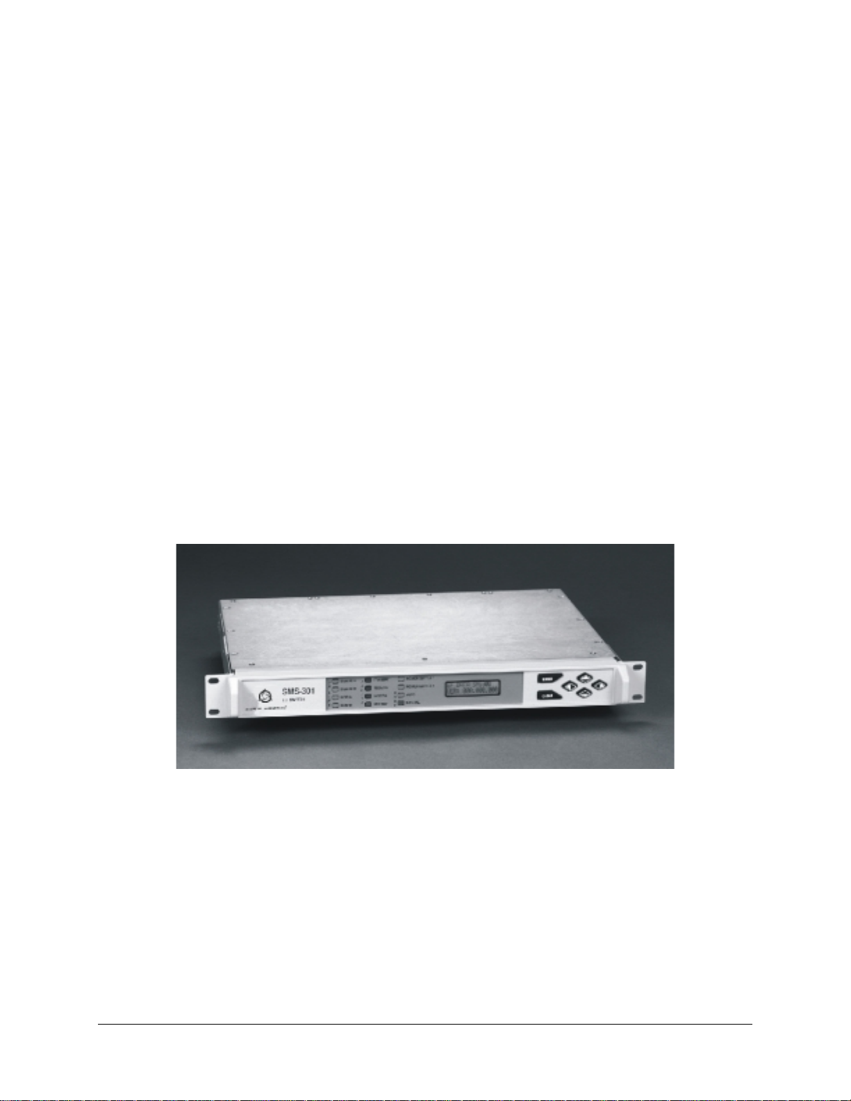
This manual describes the SMS-301 redundancy switch, referred to in this manual as the
“1:1 switch” (Figure 1-1).
Figure 1-1. SMS-301
Rev. 3 1–1
Page 16
Introduction SMS-301 Redundancy Switch
1.1 Description
1.1.1 Description (Standard Configuration)
The 1:1 switch is a fully automated protection switch for Comtech EFData satellite
modems, providing redundancy for one prime modem using one identical backup
modem. Common interfaces are provided for user data terminal equipment and
uplink/downlink RF equipment, as well as the primary and redundant (backup) modems.
The integrated uplink 1:1 switch and downlink splitter operate at IF frequencies in the
range of 50 to 180 MHz.
Full Monitor and Control (M&C) functions are supported by an integrated
microprocessor system. The M&C system is designated to maintain the 1:1 switch
configuration settings in non-volatile memory for at least one year without prime power.
Note:
While 1:1 switch prime power is not applied, the default connections are to
Modem A.
Remote control is provided by an EIA-485 or EIA-232 interface located on the rear panel
of the chassis. The rear panel also is the location for all external interconnections. The
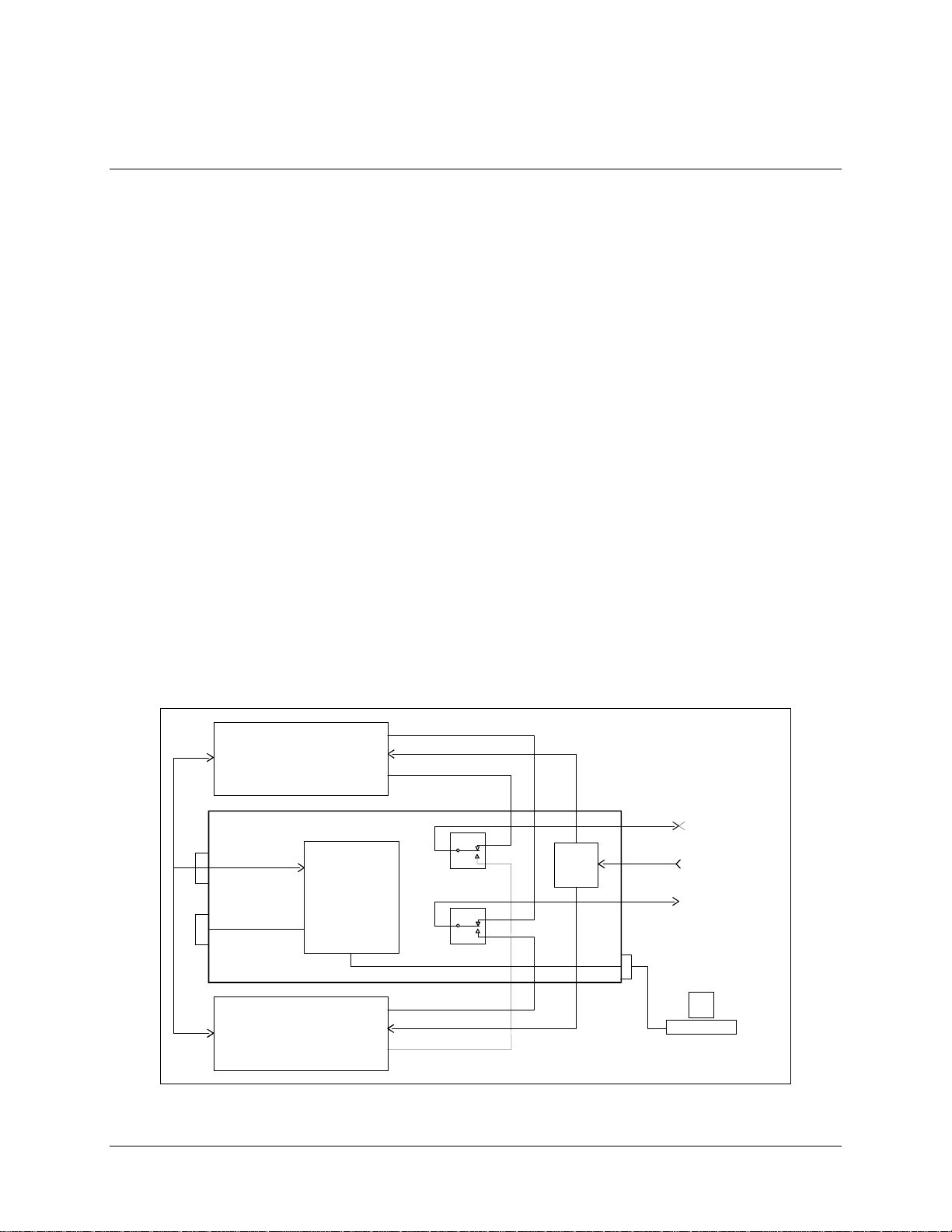
1:1 switch is enclosed in a single unit, 19-inch (48.3 cm) rack-mounted chassis. Figure 1-2
illustrates the system block diagram.
TR ANS M IT IF
RECEIVE IF
BASEBAND DATA
TX/RX
SWITCH M&C LOGIC
REMOTE
CONTROL
TR ANS M IT IF
RECEIVE IF
BASEBAND DATA
TX/RX
J9J5J2
SPLITTER
J7J6J3
J1
J8
J4
J10
EIA-232 OR
EIA-485
BASEBAND DATA
TO/FROM CUSTOMER
RECEIVE IF
50 TO 180 MHz F R O M
DOWN CONVERTER
TR ANS M IT IF
50 TO 180 MHz
TO U P C O N VE R T E R
HOT TERMINAL
OR COMPUTER
J14
MODEM A
1 FOR 1 SWITCH
MODEM REMOTEJ13
EIA-485
STATUS/FAULTS
MODEM A
Figure 1-2. System Block Diagram (Standard Configuration)
1–2 Rev. 3
Page 17
SMS-301 Redundancy Switch Introduction
1.1.2 Description (With RS-301 Option)
The 1:1 switch, when used with the RS-301 Remote Switch, is a fully-automated
protection switch designed for use with the Comtech EFData SDM-300/-300A Satellite
Modem that are equipped with the 8-Channel MUX option. It provides redundancy for
the one prime modem using identical backup satellite modem. The 1:1 switch provides
common interfaces for the RF uplink and downlink equipment. The integrated uplink 1:1
switch and downlink splitter operate at IF frequencies in the range of 50 to 180 MHz.
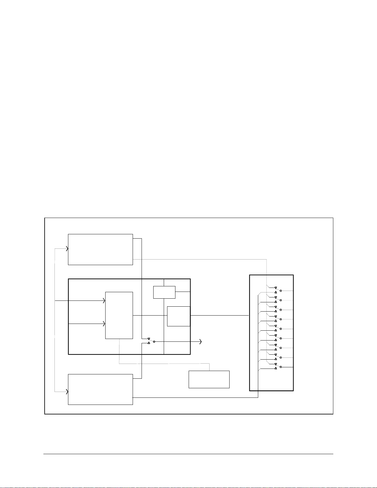
The RS-301 Remote Switch is a separate 19-inch (48.3 cm) rack-mounted chassis. It is
controlled by the 1:1 switch, and provides redundancy for the data interface between the
primary modem, backup modem, and customer equipment. The front panel provides
convenient access to eight tributary data channels (EIA-232 and EIA-422 clock and data)
and one auxiliary data channel. Figure 1-3 illustrates the system block diagram.
Note:
The default connections are to Modem A.
SDM -300 / 300A
MODEM A
1 FOR 1 S W ITCH
J13
MODEM REMOTE
EIA-485
STATUS FAULTS
J14
SDM -300 / 300A
MODEM B
TRANSMIT IF
RE C EIV E IF
BASEBAND DATA
TX/RX
SWITCH
M&C
LOGIC
REMO TE
CONTRO L
J10 J6
TRANSMIT IF
RE C EIV E IF
BASEBAND DATA
TX/RX
J5
J9
SPLITTER
CONTRO L
BUS
EXTENDER
CARD
J7
EIA-232 OR EIA-485
M O DEM A D ATA ( 8 T R IB & A UX )
NOTE: J7, J8, AND J9
AR E N O T US E D.
J8
J1
J4
HO ST T ER MIN AL
OR COMPUTER
M O DEM B D ATA ( 8 T R IB & 1 A U X)
SWITCH
CONTRO L
TRANSMIT IF
50 TO 180 M Hz TO
UP CON VERTER
J16
J14
J1 TR IB 1 DATA
J2 TR IB 2 DATA
J3 TR IB 3 DATA
J4 TR IB 4 DATA
J5 TR IB 5 DATA
J6 TR IB 6 DATA
J7 TR IB 7 DATA
J8 TR IB 8 DATA
J9 AUX DATA
RS-301
REMOTE
SWITCH
J15
Figure 1-3. System Block Diagram (With RS-301 Option)
Rev. 3 1–3
Page 18

Introduction SMS-301 Redundancy Switch
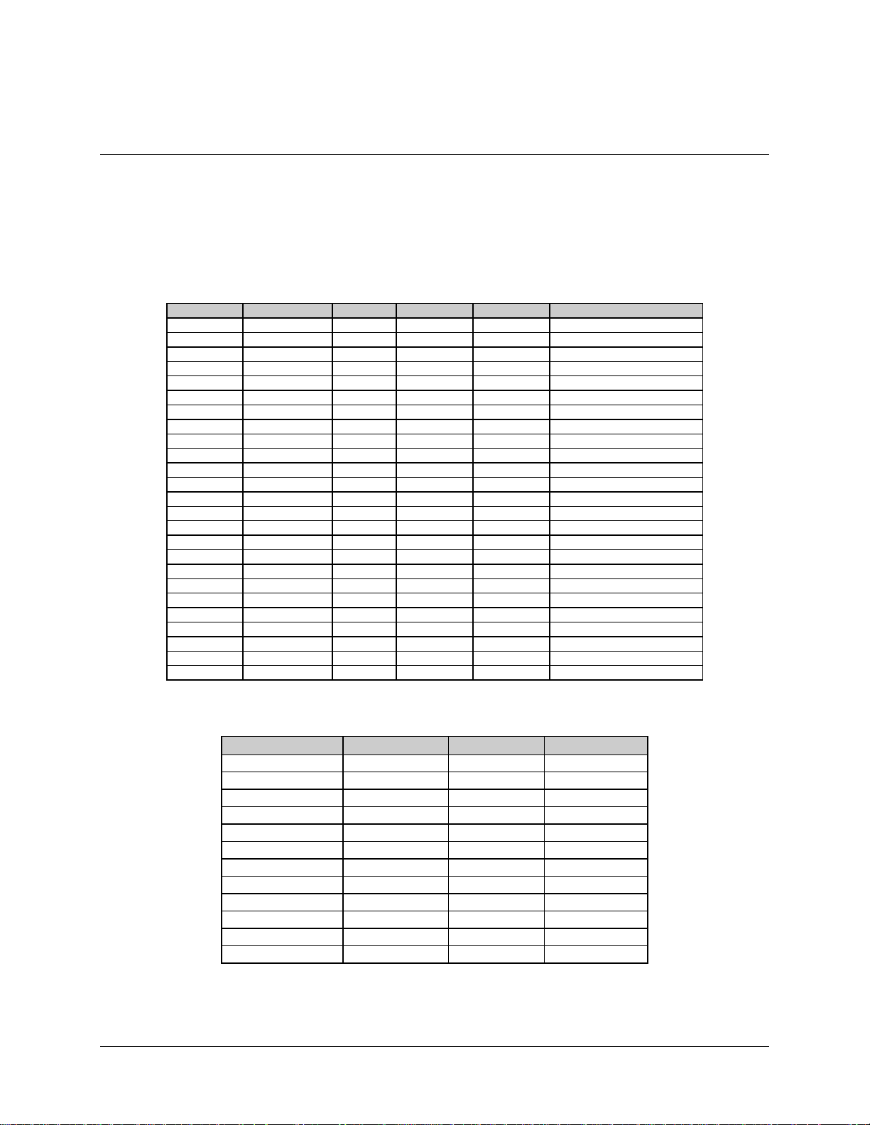
1.1.3 Board List
The following boards, listed in Table 1-1, can be installed in the SMS-301, depending on
the configuration.
Table 1-1. Board List
Board Type Drawing #
M&C, 75
M&C, 50
IBS, IDR, ASYNC, D&I,
50-pin Data, I/O (J1, J2, J3)
EIA-422/-449, G.703, V.35,
37-pin Data I/O (J1, J2, J3)
LVDS-DVB TX, 37-pin Inter face PL/6201-1
EIA-422/DVB TX, 37-pin Interf a c e PL/6201-2
EIA-232/-422/-530, V.35, G.703
25-pin Data, I/O (J1, J2, J3)
100-Pin Interface (RS-301 only) PL/6592
Ω
Ω
PL/5950-1
PL/5950-2
PL/5951
PL/5952
PL/6026
PL/6627
1–4 Rev. 3
Page 19

SMS-301 Redundancy Switch Introduction
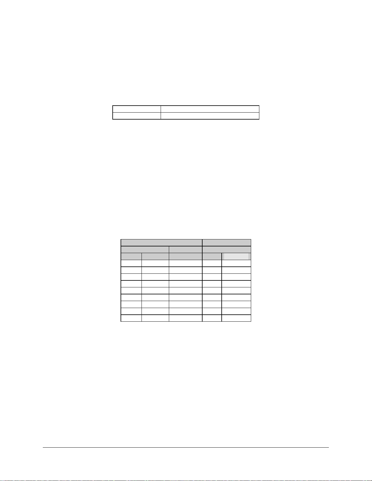
1.2 Front Panel
The front panel of the chassis is a local user interface used for control and status
monitoring of the switching system. This local user interface consists of the following:
•
Keypad
•
Backlit LED display
•
LED status indicators (Table 1-2)
Table 1-2. LED Status Indictors
Function Color
Demodulator A O n-Line Green
Demodulator B On-Line Gree n
Modulator A On-Line Green
Modulator B On-Line Green
Transmit Fault Red
Receive Fault Red
System Fault Red
Stored Fault Yellow
Power Supply 1 Green
Power Supply 2 Green
Auto Mode Green
Manual Mode Yellow
Rev. 3 1–5
Page 20

Introduction SMS-301 Redundancy Switch
1.3 Specifications
Refer to Table 1-3 for the 1:1 switch specifications.
Table 1-3. 1:1 Switch Specifications
Data Interface Switch:
Modem A, I/O
Modem B, I/O
Common, I/O
Control Bus Extender Card Connector T ype: 37-pin D-sub (Remote Switch)
IF Uplink Switch: Connector type: BNC
IF Downlink Splitter: Connector type: BNC
Local User Interface Front Panel:
Front Panel Status LEDs Oper a tiona l mode:
Connector type: 25-pin D-sub,
37-pin D-sub
50-pin D-sub
100-pin D-sub
Impedance: 75Ω (50Ω optional)
Return loss: ≥ 18 dB
Switched input to output loss: < 1.5 dB
Frequency re spons e : 50 to 180 MHz
IF input to input isolation: > 60 dB
Impedance: 75Ω (50Ω optional)
Return loss: ≥ 18 dB
Splitter loss, input to outputs: < 4.0 dB
Output balance: ± 0.5 dB
Frequency re spons e : 50 to 180 MHz
Keypad: 6 button (enter, c le a r, le ft, right, up, down arrows)
•
Display: backlit LC D, 2 lines by 16 characters
•
Manual (Yellow)
•
Automatic (Gree n)
•
Switch faults:
TX (Red)
•
RX (Red)
•
System (Red)
•
Stored (Yellow)
•
On-line Status:
Modulator A (Gre e n)
•
Modulator B (Green)
•
Demodulator A ( Green)
•
Demodulator B (Green)
•
On-line/Fault Status
Modulator On-line
Demodulator On-line
Switch Fault
Controller Fault
Spare
Remote Control Interface type: EIA-485/EI A-232 (local selec ta ble)
1–6 Rev. 3
Rear panel, 15-pin D-sub female
Form C relay
Form C relay
Form C relay
Form C relay
Form C relay
Connector: 9-pin D-sub
Protocol: Addressable (s ee r e mote control protocol)
Page 21

SMS-301 Redundancy Switch Introduction
Table 1-3. 1:1 Switch Specifications (Continued)
Parameters
Controlled/Monitored
Configuration Retention Will maintain conf ig uration for at least one y ea r w ithout prime power
Switch to Modem
Communications
Prime Power 85 to 264 VAC, 47 to 63 Hz, 30W (re dunda nt inputs )
Size 19 W x 15.2 D x 1.75 H inches ( 1 RU )
Weight < 9 lbs (4 kg)
Operating Temperature
Humidity < 95%, non-condensing
EMI CE Mark Certification
Operation mode: Automatic or manual
Switching mode : Independent or dependent mod/demod
Modulator on-line delay
Demodulator on-line de la y
Modem on-line: A or B (dependent m ode )
Modulator on-line: A or B (independent mode)
Demodulator on-line : A or B (independent mode)
Remote config ur a tion (loc a l only): EIA-232 or EIA -485, a ddr e ss , ba ud,
parity, bits per word
Remote mode (Sw itc h)
Clear stored faults
Current faults
Stored faults
Switch status
Firmware
Time/date
Equipment type
Store/recall multiple switc h c onfigurations
Remote access to modulator/demodulator s ta t us
Modem configur a tion c opy to opposite modem
Interface type: EIA -485 ( 2-wire)
Connector: 9-pin D-sub
Protocol: Addressable (s e e r e mote control protocol, Appe ndix A)
(Optional)
(48.3 x 39 x 4.4 cm)
0° to 50° C (32° to 122° F)
42 to 56 VDC, 40W (redundant inputs)
Rev. 3 1–7
Page 22

Introduction SMS-301 Redundancy Switch
This page is intentionally left blank.
1–8 Rev. 3
Page 23

This chapter provides installation information for the 1:1 switch, including unpacking,
inspecting the parts, and external connections.
2.1 Unpacking
The 1:1 switch and manual are packaged in pre-formed, reusable cardboard cartons
containing foam spacing for maximum shipping protection. To remove the 1:1 switch,
proceed as follows:
Do not use any cutting tool that will extend greater than 1-inch into the
container and cause damage to the 1:1 switch.
CAUTION
1. Cut the tape at the top of the carton where it is indicated OPEN THIS END.
Chapter 2.
INSTALLATION
2
2. Lift out the cardboard/foam spacer covering the 1:1 switch.
3. Remove the 1:1 switch, manual, and power cords from the carton.
4. Save the packing material for reshipment either back to the factory or to another
location.
5. Inspect the equipment for any possible damage incurred during shipment.
6. Check the equipment against the packing list to ensure that the shipment is
complete.
7. Refer to Section 2.2 for further system installation instructions.
Rev. 3 2–1
Page 24

Installation SMS-301 Redundancy Switch
2.2 System Installation
System installation instructions are dependent on whether or not the 1:1 switch is used
with the RS-301 Remote Switch option.
•
For all switch configurations where the Data I/O is switched internally to the
1:1 switch, refer to Appendix B for standard configuration installation. This
configuration is used with the SDM-300/-300A Satellite Modems with 25-pin,
34-pin, 37-pin, and 50-pin Data I/O interfaces.
•
When the RS-301 Remote Switch option is used and the Data I/O is s witched in
a separate unit, refer to Appendix B for installation with RS –301 switch
installed. This configuration is used with the SDM-300/-300A Satellite Modem
with a
100-pin Data I/O (8-channel Mux).
Note:
Refer to Appendix C for SDM-2020 cabling instructions to the switch.
2–2 Rev. 3
Page 25
SMS-301 Redundancy Switch Installation
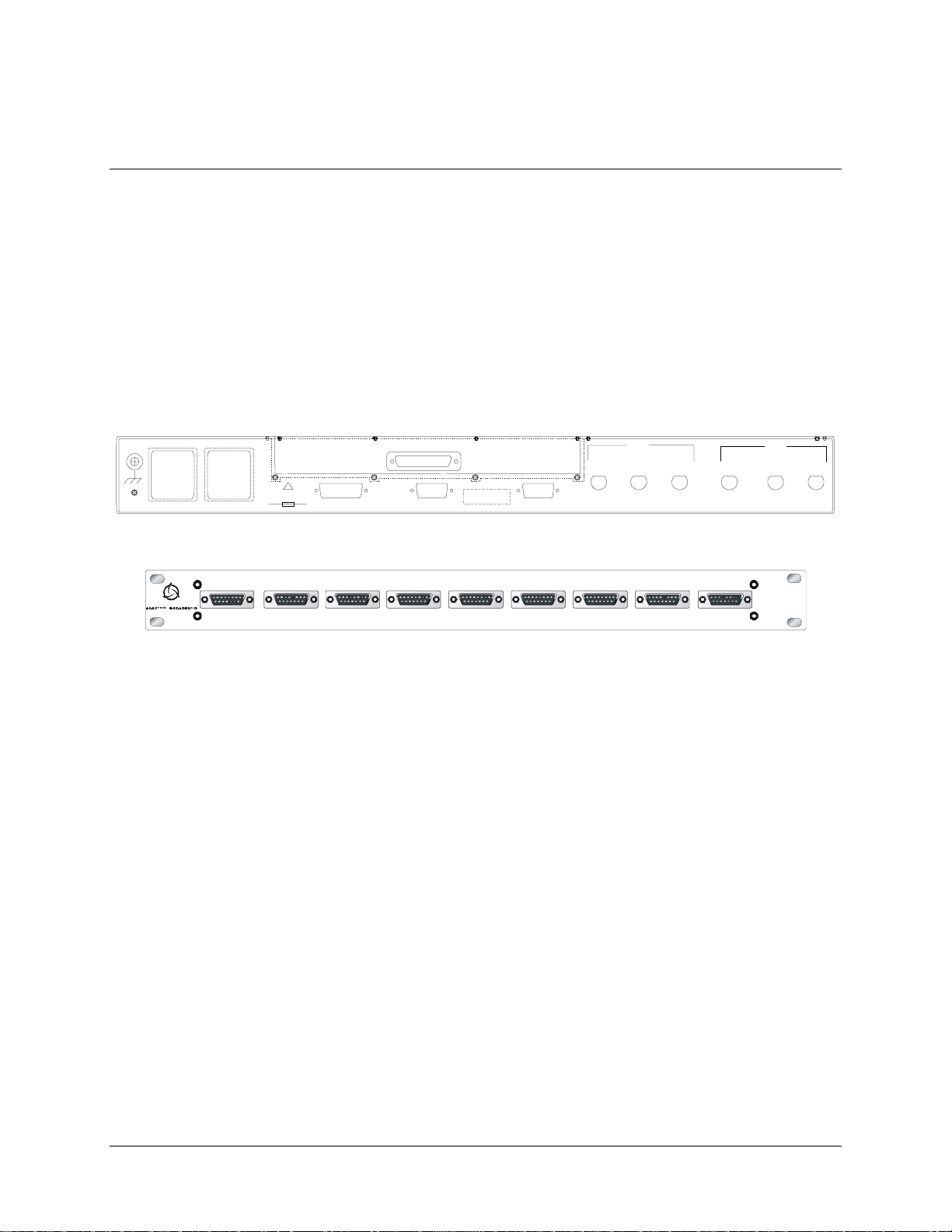
2.3 External Connections
Connections between the 1:1 switch and other equipment are performed through the rear
panel connectors. These connectors vary depending on whether the Remote Switch (RS-
301) is used.
•
Refer to Table 2-1 for the connector list when the Data I/O is switched internal
to the 1:1 switch.
•
When the 1:1 switch is used with the Remote Switch (RS-301) option, refer to
Table 2-2.
J1 REMO TE SW IT C H CO N TROL
!
100 TO 240 V
1.5 A 50 TO 60 Hz
AC1
J11
AC2
J12
T2A, 250V
STATUS/FAULTS
J14
J10 J13
REMOTE
CONTROL
MODEM
COM
J9
A
DEMOD
J8
RX IFJ7B
TX IF
MOD
J4
J5
J6
A
B
Rear Panel (Standard Configuration)
TRIB 1 DATA TRIB 2 DATA TRIB 3 DATA TRIB 4 D ATA TRIB 5 DATA TRIB 6 DATA TRIB 7 DATA TRIB 8 DATA AUX
RS-301
J7J4J1 J2 J3 J5 J6
J8
J9
Rear Panel (With RS-301 Option)
Figure 2-1. SMS-301 Rear Panel Configurations
Rev. 3 2–3
Page 26
Installation SMS-301 Redundancy Switch
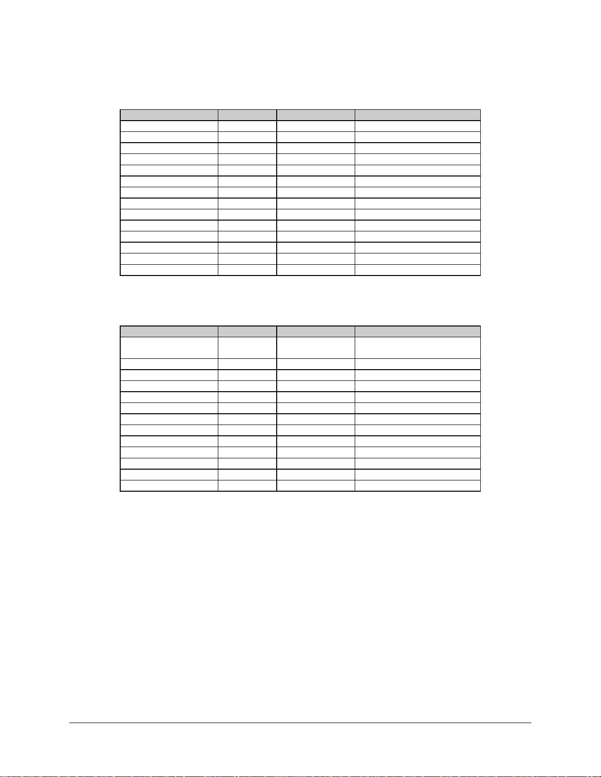
Table 2-1. Rear Panel Connectors (Standard Configuration)
Name Ref Des Connector Type Function
DATA CO M J1 50/37/25-pin D Com mon Data Interfa c e
DATA A J2 50/37/25-pin D Mode m A Data Inte rface
DATA B J3 50/37/25-pin D Modem B Data Inte rface
TX IF COM J4 BNC Common TX IF Output
TX IF A J5 BNC Modem A TX IF Input
TX IF B J6 BNC Modem B TX IF Input
RX IF B J7 BNC Modem B RX IF Output
RX IF COM J8 BNC Comm on R X IF Input
RX IF A J9 BNC Modem A RX IF Output
REMOTE CONTR OL J10 9-pin D Remote Comma nd I nte rface
AC POWER J11/J12 IEC AC Power I nput
SW/MODEM COMM J13 9-pin D Modem A/B Remote
STATUS/FA U L TS J14 15-pin D Switch Status (Form C relay)
GND GND #10-32 stud Ground
Table 2-2. Rear Panel Connectors (With RS-301 Option)
Name Ref Des Connector Type Function
REMOTE SWITCH
CONTROL
TX IF COM J4 BNC Common TX IF Output
TX IF A J5 BNC Modem A TX IF Input
TX IF B J6 BNC Modem B TX IF Input
RX IF B J7 BNC Modem B RX IF Output
RX IF COM J8 BNC Comm on R X IF Input
RX IF A J9 BNC Modem A RX IF Output
REMOTE CONTR OL J10 9-pin D Remote Comma nd I nte rface
AC POWER J11/J12 IEC AC Power I nput
DC POWER
SW/MODEM COMM J13 9-pin D Modem A/B Remote
STATUS/FA U L TS J14 15-pin D Switch Status (form C relay )
GND GND #10-32 stud Ground
Note:
(Optional)
The use of each connector is described in the following paragraphs.
J1 37-pin D RS-301 Control Signa ls , Pow e r,
and Ground
J11/J12 Terminal B loc k DC Power Input
2–4 Rev. 3
Page 27

SMS-301 Redundancy Switch Installation
2.3.1 Remote Switch Control (J1) (RS-301 Option)
For applications using the Remote Switch (RS-301) option, the connector type is a
37-pin D subminiature. Refer to Table 2-3 for the 37-pin connector pin assignments.
Table 2-3. Switch Control Interface Signals
Pin No. Name Function
1 SCL Serial Clock
20 SDA Serial Data
2 Spare 11 No Connection
21 Spare 10 No Connection
3 Spare 9 No Connection
22 Spare 8 No Connection
4 Spare 7 No Connection
23 Spare 6 No Connection
5 Spare 5 No Connection
24 Spare 4 No Connection
6 Spare 3 No Connection
25 Spare 2 No Connection
7 Spare 1 No Connection
26 DMDONL Demod Online
8 MODONL Mod Online
27 /B_DF Modem B D e mod Fault
9 /A_DF Modem A Demod Fault
28 /B_MF Modem B Mod Fault
10 /A_MF Modem A Mod Fault
29 ID_5 Interface Board ID
11 ID_4 Interface Board ID
30 ID_3 Interface Board ID
12 ID_2 Interface Board ID
31 ID_1 Interface Board ID
13 GND Ground
32 GND Ground
14 GND Ground
33 GND Ground
15 GND Ground
34 -12V -12VDC
16 -12V -12VDC
35 +12V +12VDC
17 +12V +12VDC
36 +5V + 5VD C
18 +5V + 5VD C
37 +5V + 5VD C
19 +5V + 5VD C
Rev. 3 2–5
Page 28
Installation SMS-301 Redundancy Switch
2.3.2 Data I/O Connections
The 1:1 switch data interface is dependent upon the installed switchboard. These are
described in the following sections.
2.3.2.1 Data I/O Connector (J1, J2, J3), 50-Pin (PL/5951)
Note:
For ASYNC, IBS, IDR, and D&I applications.
In order to maintain comp atibility with various Comtech EFData break out panels, the 50pin D subminiature connector has the assignments shown in Table 2-4, depending upon the
current operating mode.
Table 2-4. Data I/O Connector, 50-Pin
50-Pin D Connector
Pin # IDR IBS Async D&I
34 G.703 SDA In G.703 SDA In G.703 SDA In G.703 SDA In
18 G.703 SDB I n G.703 SDB I n G.703 SDB In G.703 SDB In
36 G.703 RDA Out G.703 RDA Out G.703 RDA Out G.703 RDA Out
20 G.703 RDB Out G .703 RD B O ut G.703 RDB Out G.703 RDB Out
35 EIA- 422 Ex tClkA In V.35/EIA-422 EXCA In V.35/EIA- 422 E X CA In EIA-422 EXCA In
19 EIA-422 E x tClkB In V.35/EIA-422 EXCB In V.35/EIA-422 EX CB In EIA- 422 EX CB In
37 EIA- 422 8k TXDA In V.35/EIA - 422 S D - A In V.35/EIA-422 S D - A In G.703 DDO-A Out
38 EIA- 422 8k TXDB In V.35/EIA-422 SD-B In V.35/EIA-422 SD-B In G.703 DDO-B Out
21 EIA- 422 8k TClkA Out V.35/EIA - 422 S T-A Out V.35/EIA-422 ST- A Out
22 EIA- 422 8k T C l kB O ut V.35/EIA-422 S T-B Out V.35/EI A-422 ST-B O ut
4 EI A-422 TXOctA In ESC TXDB In (EIA-485 only)
5 EI A-422 TXOctB In ESC TXDA I n ( E IA-232 onl y) ESC TXD A In (EIA-485 & 232) ESC TX D In (EI A-232 only )
39 EIA- 422 8k RX D A Out V.35/EI A-422 RD-A O ut V.35/EIA-422 RD-A O ut G.703 I D I-A In
40 EIA-422 8k RXDB Out V.35/EIA-422 RD-B Out V.35/EI A-422 RD-B Out G.703 IDI-B In
23 EIA-422 8k RClkA Out V.35/EIA-422 RT - A Out V.35/EI A-422 RT-A O ut G.703 IDI-B I n
24 EIA-422 8k RClkB Out V.35/EIA - 422 RT-B Out V.35/EIA - 422 RT-B Out
6 EI A-422 RXOctA O ut ESC RXDB Out (EIA-485 onl y)
7 EI A-422 RXOctB Out ESC RXDA Out (EIA-232 only ) ESC RXDA Out (EI A-485 & 232) ESC RXD Out (EIA - 232)
45 Aud1-A In (or 64SDA) V.35/EIA - 422 RTS-A V.35/EIA - 422 RTS-A
29 Aud1-B In ( o r 64S D B) V.35/EIA - 422 RTS-B V.35/EIA-422 RTS- B
44 BWO4_NO SECONDARY_NO SECONDARY_NO
12 BWAI 1 V.35/EIA - 422 S CTE/TT A V.35/EIA-422 SCTE/T T A
13 BWAI 2 V.35/EIA - 422 S CTE/TT B V.35/EIA-422 SCTE/T T B
14 BWAI 3 EIA-422 TX Oct A
15 BWAI 4 EIA-422 TX Oct B
17 Def Maint Alr m
16 Demod Fault C
50 Demod Fault NO
3 AGC Out AGC Out AGC Out AGC Out
49 MF (Open Col lector) MF (Ope n Collector ) MF ( O pen Collecto r ) MF (Open Collector)
33 DF (Open Co l lector) DF (Open Collecto r ) DF (Open Co l lector) DF (Open Collector)
1, 2 Ground
2–6 Rev. 3
Page 29
SMS-301 Redundancy Switch Installation
2.3.2.2 Data I/O Connector (J1, J2, J3), 37-Pin (PL/5952)
Note:
For EIA-422/-449, V.35, and G.703 applications.
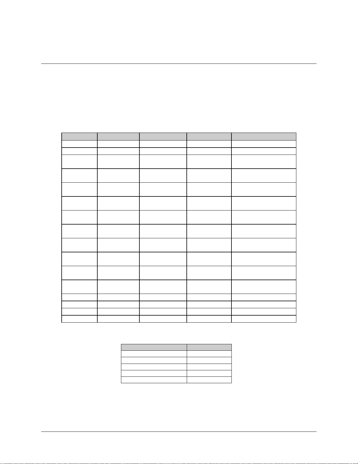
The 37-pin D subminiature connector pin assignments are shown in Table 2-5.
Table 2-5. Data I/O Connectors, 37-Pin
Pin # EIA-422/-449 V.35 G.703 Signal Function
1 SG SG SG Signal Ground
3 MF MF MF MOD Fault
4
22
5
23
6
24
7
25
8
26
9
27
11
29
13
31
17
35
16
34
19 SG SG SG Signal Ground
20 SG SG SG Signal Ground
21 DF DF DF DEMOD Fault
37 SG SG SG Signal Ground
SD-A
SD-B
ST-A
ST-B
RD-A
RD-B
RS-A
RS-B
RT-A
RT-B
CS-A
CS-B
DM-A
DM-B
RR-A
RR-B
TT-A
TT-B
MC-A
MC-B
SD-A
SD-B
ST-A
ST-B
RD-A
RD-B
RS-A
RS-B
RT-A
RT-B
CS-A
CS-B
DM-A
DM-B
RR-A
RR-B
TT-A
TT-B
MC-A
MC-B
SD-A
SD-B
RD-A
RD-B
MC-A
MC-B
Send Data
Send Timing
Receive Data
Request to Send
Receiver Timing
Clear to Send
Data Mode
Receiver Ready
Terminal Ti ming
Master Clock
(Input)
The following shows the jumper configurations for EIA-422/449, V.35, and G.703.
EIA-422/449/V.35 G.703
JP2 JP1
JP3 JP6
JP4 JP7
JP5 JP6
JP9
Rev. 3 2–7
Page 30
Installation SMS-301 Redundancy Switch
2.3.2.3 Data I/O Connector (J1, J2, J3), 25-Pin (PL/6026)
ote:
N
For EIA-422/-530, EIA-232, V.35, or G.703 applications,
The 25-pin D subminiature connector has the pin assignments shown in Table 2-6.
Table 2-6. Connector Assignments, 25-Pin
Pin # EIA-422/-530 EIA-232 V.35 G.703 Signal Function
3 RD-A RXD RD-A RD-A Receiv e D ata
16 RD+B RD+B RD +B
2 SD-A TXD SD-A SD-A Send Data
14 SD+B SD+B SD+B
24 TT-A TXC SCTE--A Terminal Timing
11 TT+B SCTE+B
15 ST-A ST SCT-A Send Timing
12 ST+B SCT+B
17 RT- A RXC SCR-A Receiver Timing
9 RT-B SCR-B
4 RS-A RTS RTS Request to Send
19 RS+B
5 CS-A CTS CTS Clear to Send
13 CS+B
8 RR-A DCD RLSD Receiver Ready
10 RR+B
6 DM-A DSR DSR Data Mode
22 DM+B
20 MC-A MC MC-A MC-A Master Clock (input)
23 MC+B MC+B MC+B
18 LL LL LL
21 DF DF DF DF Demod Fault
25 MF MF MF MF Mod Faul t
7 SIGGND SIGGND SIGGND SIGGND Signal Ground
1 SHLD SHLD SHLD SHLD
The following shows the jumper configurations for EIA-422/530.
EIA-422/-530 V.35 EIA-232 G.703
J6 J6 J19 J5
J7 J7 J23 J10
J8 J8 J24 J11
J9 J9 J25 J12
J14 J14 J27 J13
J15 J15 J28 J14
J17 J16 J29 J18
J18 J18 J30 J20
J20 J20 J17 J21
J21 J21 J22
J22 J22 J26
J26 J26
2–8 Rev. 3
Page 31

SMS-301 Redundancy Switch Installation
2.3.2.4 Data I/O (J1, J2, J3) 37-Pin (PL/6201-1)
Note:
For EIA-422/LVDS DVB (Serial or Parallel) Interface applications.
The 37–pin D subminiature connector has the pin assignments shown in Table 2-7.
Table 2-7. Connector Assignments, 37-Pin
Pin # Signal Function/Name Comment
1 Signal GND Mod/Demod
2 REF CLK/GND B REF CLK
3 MF Mod Fault
4 NC No Connection
5 NC No Connection
6D0B Data
7D1 B Data
8D2 B Data
9D3 B Data
10 D4 B Data
11 D5 B Data
12 D6 B Data
13 D7 B Data
14 Valid B Valid
15 SYNC B SYNC
16 NC No Connection
17 NC No Connection
18 NC No Connection
19 CLK A Clock
20 NC No Connection
21 REF CLK/GND A REF CLK
22 DF Demod Fault
23 NC No Connection
24 NC No Connection
25 D0 A Data
26 D1 A Data
27 D2 A Data
28 D3 A Data
29 D4 A Data
30 D5 A Data
31 D6 A Data
32 D7 A Data
33 Valid A Valid
34 SYNC A SYNC
35 NC No Connection
36 NC No Connection
37 CLK B Clock
Rev. 3 2–9
Page 32

Installation SMS-301 Redundancy Switch
2.3.2.5 Data I/O Connector (J1, J2, J3) 37-Pin (PL/6201-2)
Note:
For EIA-422 Serial Interface applications.
The 37–pin D subminiature connector has the pin assignments shown in Table 2-8.
Table 2-8. Connector Assignments, 37-Pin
Pin # Signal Function/Name Comment
1 Signal GND Mod/Demod
2 Send Timing (ST-B) Modulator
3 Modulator Fault (MF) Modulator
4NC NC
5NC NC
6NC NC
7NC NC
8NC NC
9 Clear To Send (CS-A) Modulator
10 NC NC
11 NC NC
12 NC NC
13 Send Data (SD-B) Modulator
14 Request To Send (RS-B) Modulator
15 NC NC
16 NC NC
17 NC NC
18 NC NC
19 Terminal Timing (TTA) Modulator
20 NC NC
21 Send Timing (TT-A) Modulator
22 NC NC
23 NC NC
24 NC NC
25 NC NC
26 NC NC
27 Clear To Send (CS-B) Modulator
28 NC NC
29 NC NC
30 NC NC
31 NC NC
32 Send Data (SD-A) Modulator
33 Request To Send (RS-A) Modulator
34 NC NC
35 NC NC
36 NC NC
37 Terminal Timing (TT-B) Modulator
2–10 Rev. 3
Page 33

SMS-301 Redundancy Switch Installation
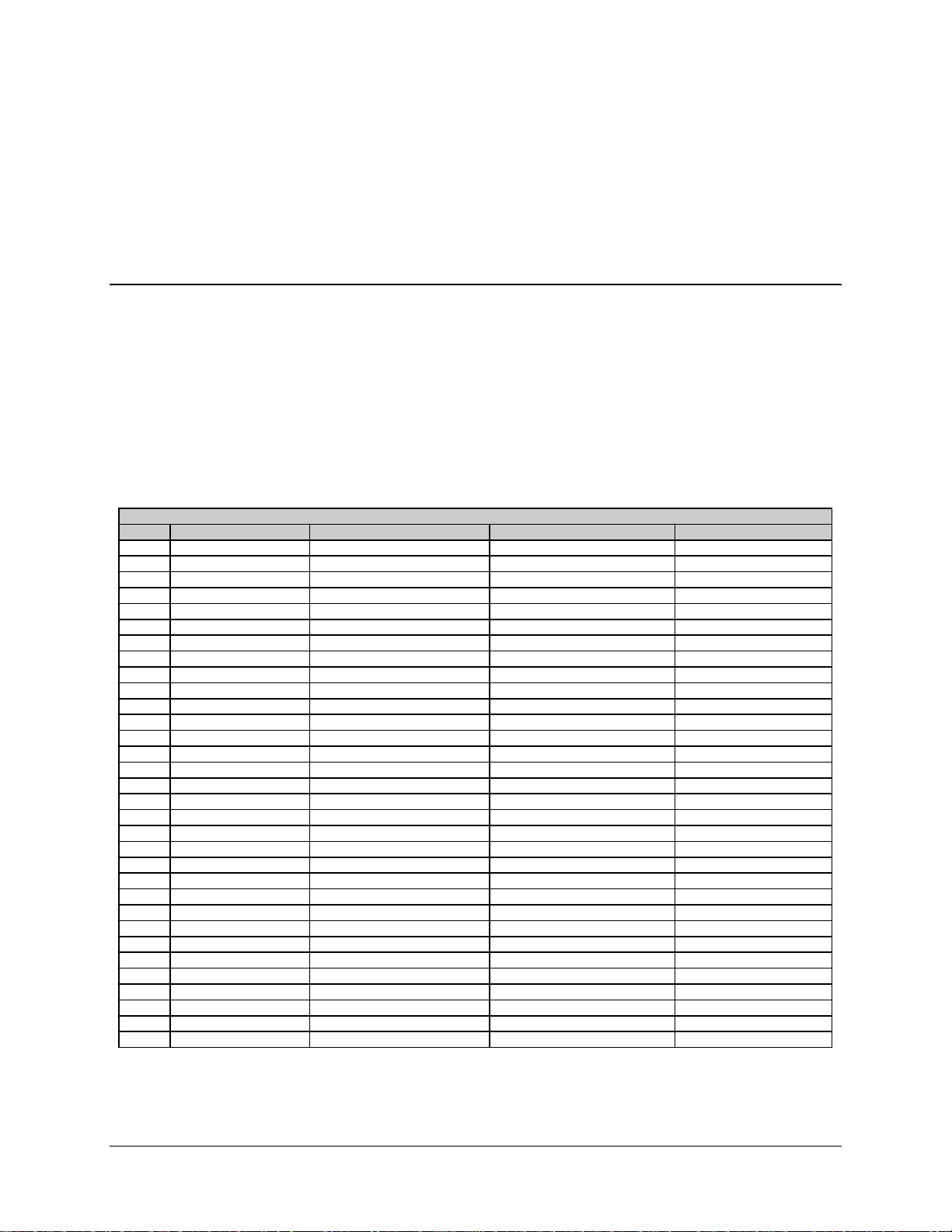
2.3.2.6 100 Pin interface (RS-301 Option) (PL/6542/PL/6627)
The 100-pin connector pin assignments is shown in Table 2-9.
Table 2-9. Data I/O Connector, 100-Pin
Pin # Circuit Description Pin # Circuit Description
1 – N/A 51 GND GROUND
2 – N/A 52 TC232 5 EIA-232, TX CLK , TRIB5
3 – N/A 53 TD232 5 EIA-232, TX DAT, TRIB5
4 – N/A 54 CTS232 5 EIA-232, CTS, TRIB5
5 GND GROUND 55 TD422B 5 EIA-422, TX DATB (+), TRIB5
6 GND GROUND 56 TD422A 5 EIA-422, TX DATA (–), TRIB5
7 DF DEMOD FAULT 57 TC422B 5 EIA-422, TX CLKB (+), TRIB5
8 MF MOD FAULT 58 TC422A 5 EIA-422, TX CLKA (–), TRIB5
9 GND GROUND 59 CTS422B 5 EIA-422, CTSB (+), TRIB5
10 RT+B RECEIVE TIMING B (+) 60 CTS422A 5 EIA-422, CTSA (–), TRIB5
11 RT–A RECEIVE TIMING A (–) 61 GND GROUND
12 GND GROUND 62 TC232 4 EIA-232, TX CLK , TRIB4
13 RD+B RECEIVE DATA B (+) 63 TD232 4 EIA-232, TX DAT, TRIB4
14 RD–A RECEIVE DATA A (–) 64 CTS232 4 EIA-232, CTS, TRIB4
15 GND GROUND 65 TD422B 4 EIA-422, TX DATB (+), TRIB4
16 RR+B RECEIVER READY B (+) 66 TD422A 4 EIA-422, TX DATA (–), TRIB4
17 RR–A RECEIVER READY A (–) 67 TC422B 4 EIA-422, TX CLKB (+), TRIB4
18 GND GROUND 68 TC422A 4 EIA-422, TX CLKA (–), TRIB4
19 MCB MASTER CLOCK B (+) 69 CTS422B4 EIA-422, CTSB (+), TRIB4
20 MCA MASTER CLOCK A (–) 70 CTS422A4 EIA-422, CTSA (–), TRIB4
21 GND GROUND 71 GND GROUND
22 TC232 8 EIA-232, TX CLK , TRIB8 72 TC232 3 EIA-232, TX CLK , TRIB3
23 TD232 8 EIA-232, TX DAT, TRIB8 73 TD232 3 EIA-232, TX DAT, TRIB3
24 CTS232 8 EIA-232, CTS, TRIB8 74 CTS232 3 EIA-232, CTS, TRIB3
25 TD422B 8 EIA-422, TX DATB (+), TRIB8 75 TD422B 3 EIA-422, TX DATB (+), TRIB3
26 TD422A 8 EIA-422, TX DATA (–), TRIB8 76 TD422A 3 EIA-422, TX DATA (–), TRIB3
27 TC422B 8 EIA-422, TX CLKB (+), TRIB8 77 TC422B 3 EIA-422, TX CLKB (+), TRIB3
28 TC422A 8 EIA-422, TX CLKA (–), TRIB8 78 TC422A 3 EIA-422, TX CLKA (–), TRIB3
29 CTS422B8 EIA-422, CTSB (+), TRIB8 79 CTS422A3 EIA-422, CTSB (+), TRIB3
30 CTS422A8 EIA-422, CTSA (–), TRIB8 80 CTS422A3 EIA-422, CTSA (–), TRIB3
31 GND GROUND 81 GND GROUND
32 TC232 7 EIA-232, TX CLK , TRIB7 82 TC232 2 EIA-232, TX CLK , TRIB2
33 TD232 7 EIA-232, TX DAT, TRIB7 83 TD232 2 EIA-232, TX DAT, TRIB2
34 CTS232 7 EIA-232, CTS, TRIB7 84 CTS232 2 EIA-232, CTS, TRIB2
35 TD422B 7 EIA-422, TX DATB (+), TRIB7 85 TD422B 2 EIA-422, TX DATB (+), TRIB2
36 TD422A 7 EIA-422, TX DATA (–), TRIB7 86 TD422A 2 EIA-422, TX DATA (–), TRIB2
37 TC422B 7 EIA-422, TX CLKB (+), TRIB7 87 TC422B 2 EIA-422, TX CLKB (+), TRIB2
38 TC422A 7 EIA-422, TX CLKA (–), TRIB7 88 TC422A 2 EIA-422, TX CLKA (–), TRIB2
39 CTS422B7 EIA-422, CTSB (+), TRIB7 89 CTS422B2 EIA-422, CTSB (+), TRIB2
40 CTS422A7 EIA-422, CTSA (–), TRIB7 90 CTS422A2 EIA-422, CTSA (–), TRIB2
41 GND GROUND 91 GND GROUND
42 TC232 6 EIA-232, TX CLK , TRIB6 92 TC232 1 EIA-232, TX CLK , TRIB1
43 TD232 6 EIA-232, TX DAT, TRIB6 93 TD232 1 EIA-232, TX DAT, TRIB1
44 CTS232 6 EIA-232, CTS, TRIB6 94 CTS232 1 EIA-232, CTS, TRIB1
45 TD422B 6 EIA-422, TX DATB (+), TRIB6 95 TD422B 1 EIA-422, TX DATB (+), TRIB1
46 TD422A 6 EIA-422, TX DATA (–), TRIB6 96 TD422A 1 EIA-422, TX DATA (–), TRIB1
47 TC422B 6 EIA-422, TX CLKB (+), TRIB6 97 TC422B 1 EIA-422, TX CLKB (+), TRIB1
48 TC422A 6 EIA-422, TX CLKA (–), TRIB6 98 TC422A 1 EIA-422, TX CLKA (–), TRIB1
49 CTS422B6 EIA-422, CTSB (+), TRIB6 99 CTS422B1 EIA-422, CTSB (+), TRIB1
50 CTS422A6 EIA-422, CTSA (–), TRIB6 100 CTS422A1 EIA-422, CTSA (–), TRIB1
MUX Data 100-Pin Rear Panel Connector
Rev. 3 2–11
Page 34

Installation SMS-301 Redundancy Switch
2.3.3 Transmit IF Connectors (J4, J5, J6)
The transmit IF switch connectors are as follows:
• The TX IF output of the prime modem connects to TX IF A.
• The TX IF output of the backup modem connects to TX IF B.
• TX IF COMM is the transmit IF output connector and connects to the uplink IF
equipment. The TX IF output of the on-line modem will be available at
this connector.
• The characteristic impedance of these BNC connectors is 75Ω (50Ω optional).
• If the backup or prime modem is disconnected for any reason, place a 75Ω (50Ω
optional) termination on the unused connector for a 75Ω (50Ω optional) system,
respectively.
2.3.4 RX IF Connectors (J7, J8, J9)
The Receive IF splitter connectors are as follows:
• The RX IF of the prime modem connects to RX IF A and the RX IF of the
backup modem connects to RX IF B.
• RX IF COM connects to customer-furnished equipment.
• The characteristic impedance of these BNC connectors is 75Ω (50Ω optional).
• There will be less than 4 dB loss between the common input and the A or B
output connectors.
• If the backup or prime modem is disconnected for any reason, place a 75Ω
(50Ω optional) termination on the unused connector for a 75Ω (50Ω optional)
system, respectively.
2–12 Rev. 3
Page 35
SMS-301 Redundancy Switch Installation
2.3.5 Remote Control Interface Connector (J10)
The remote control interface (J10) connector is described in the following listings.
Pinout data is included in Table 2-10.
Connector type 9-pin D subminiature, female
Signal type EIA-232 or EIA-485, user-selectable
Interface connector type:
• EIA-485 (2-wire or 4-wire)
•
EIA-232 (Optional)
• Baud rate range 150 to 19.2 kbit/s
• ASCII characters
• 11 bits per character (maximum):
1 start bit
♦
7 information bits, 1 parity bit (odd/even) or
♦
8 information bits, 0 parity bit, 1 stop bit
2 stop bits
♦
Table 2-10. Remote Control Interface Connector Pinout Data (J10)
EIA-485 EIA-232
4-Wire 2-Wire
Pin # Name Name Pin # Name
1GND 1
22RD(RX)
33TD (TX)
4 +TX +TX/+RX 4
5 -TX -TX/-RX 5 GND
66DSR
77RTS
8 +RX +RX/+TX 8 CTS
9 -RX -RX/-TX 9
Notes:
(For EIA-485 4-wire operation)
1. Pins 4 and 8 may be tied together.
2. Pins 5 and 9 may be tied together.
Rev. 3 2–13
Page 36

Installation SMS-301 Redundancy Switch
2.3.6 Prime Power
2.3.6.1 AC Power (J11 and J12)
Refer to Table 2-11 for AC prime power requirements.
Table 2-11. AC Power (J11 and J12)
Description Requirements
AC power is supplied ind ependently to each
of the two power supplies by two standard
detachable, non-locking, 3-prong power
cords.
Maximum Power consumption 30W
Input Range 85 to 264 VAC
Changing Input Voltage No reconfiguration is required.
85 to 264 VAC
2.3.6.2 DC Power (J11 and J12) (Optional)
Refer to Table 2-12 for DC prime power requirements.
Table 2-12. DC Prime Power (J11 and J12)
Description Requirements
Input Range 42 to 56 VDC
Maximum Power Consumption 40W
2–14 Rev. 3
Page 37

SMS-301 Redundancy Switch Installation
2.3.7 Switch/Modem Communications Interface Connector (J13)
The switch/modem communications interface (J13) connector is described in the
following listings and pinout data is included in Table 2-13.
Interface type:
• EIA-485 (2-wire)
• Baud rate range 9.6 or 19.2 kbit/s
• ASCII characters
• 11 bits per character:
! 7 information bits
! 2 stop bits
! 1 parity (Even)
! 1 start bit
Table 2-13. Switch/Modem Communications
Interface Connector (J13)
Pinout
Pin # Name (2-Wire)
1GND
2
3
4+TX, +RX
5-TX, -RX
6
7
8+RX, +TX
9-RX, -TX
Rev. 3 2–15
Page 38

Installation SMS-301 Redundancy Switch
2.3.8 Status/Fault (J14)
Refer to Table 2-14 for Status/Faults (J14) pinout assignments.
Connector-Type: 15-Pin D Subminiature, female Form C contact
Rating 2A maximum @ 30 VDC, 0.6A @ 125 VAC
Table 2-14. Status/Faults (J14) Pinout Assignments
Pinout
Pin # Name Function
1Spare COM
2Spare NO
3Spare NC
4CEQ COM
5 CEQ NO Common Equipment OK
6 CEQ NC Common Equipment Faulted
7 M ODONL COM
8 MODONL NO Mod B On-line Status
9 MODONL NC Mod A On-line Status
10 SW COM
11 SW NO Switch OK
12 SW NC Switch Faulted
13 DMDONL COM
14 DMDONL NO Demod B On-lin e S t atus
15 DMDONL NC Demod A On-line Status
2.3.9 IF Connections: Transmit and Receive
The data is provided in the following listing:
Connector type
Return loss
BNC 75Ω (50Ω Optional)
18 dB from 50 to 180 MHz
≥
2.3.10 Ground
A #10-32 stud is provided on the rear of the chassis for connecting a common chassis
ground between all of the equipment.
2–16 Rev. 3
Page 39

This chapter defines the controls and procedures for configuration and operation of the
1:1 switch.
Note:
Familiarization with the front panel controls (Figure 3-1) and/or the related remote
commands described in Appendix A is recommended by Comtech EFData.
3.1 Configuration
The configuration of the 1:1 switch may be performed from the front panel, or from a
terminal or personal computer connected to the 1:1 switch remote port (J10). Each front
panel menu screen, from which entries can be made or status displayed, has a
corresponding remote command(s). Unlike the remote commands, the front panel display
menus are designed to sequentially guide the operator through the configuration process.
Chapter 3.
OPERATION
3
Note:
Refer to the menu tables presented in this chapter for specific configuration
information.
Upon completion of the 1:1 switch installation, as described in Chapter 2, the prime
modem attached to the 1:1 switch shall be programmed prior to the initial configuration
of the switch.
Figure 3-1. SMS-301 Front Panel View
Rev. 3 3-1
Page 40

Operation SMS-301 Redundancy Switch
3.2 Setup and Configuration
Table 3-1 details the default configuration parameters of the 1:1 switch. The 1:1 switch
is returned to this default configuration by performing a hard reset, or upon
failure/corruption of non-volatile memory.
Table 3-1. Default Configuration Parameters
Parameter Condition
Operation Mode Automatic
On-line Modem A
On-line Mod A
On-line Demod A
Switch Mode Independent
Modem Delay 0.0
Mod Delay 0.0
Demod Delay 0.0
Modulators Active
Demodulators Active
Time 12:00:00 AM
Date 7/04/76
Remote Baud Rate 9600 bit/s Even
Remote Address 10
Remote Type EIA-485 (2-wire)
Display Contrast Level 64
Automatic Verify Disable
Modem A Address 1
Modem B Address 2
Modem Baud Rate 9600 bit/s
The following sections detail the minimum modifications necessary to set up a typical
1:1 redundant configuration. In the following setup descriptions, it is assumed Modem A
connections are to the prime modem. While proper switch operation does not require
Modem A to be the prime modem, it should be noted that upon loss of prime power to
the 1:1 switch, Modem A is the default signal pass through path.
3-2 Rev. 3
Page 41

SMS-301 Redundancy Switch Operation
3.2.1 Utility System
Prior to configuration, it may be necessary to modify the following:
Display Contrast Adjust for optimum viewing in local ambient lighting
conditions.
Remote Options If a remote is to be used, appropriate remote options can be
verified or defined from the Utilities menu.
Modem Control Baud Rate Select the highest common baud rate for the modems
attached to the 1:1 switch.
3.2.2 Configuration
Upon completion of the installation, the 1:1 switch is ready for configuration to the
specific application requirements.
Note:
The normal operating mode is AUTOMATIC, which shall be changed to
MANUAL when locally configuring the 1:1 switch.
3.2.2.1 Prime
To configure the 1:1 switch for operation with the prime modem, set the following:
Address Enter a unique 3-digit decimal address for remote communications.
Mod/Demod ON or OFF; Must be ON for consideration by the switch algorithm.
Switching Mode Select INDEPENDENT or DEPENDENT RX/TX switching.
Note:
INDEPENDENT mode switching can be used to switch the modulator and/or the
demodulator. DEPENDENT mode switching always switches the modulator and
demodulator.
Rev. 3 3-3
Page 42

Operation SMS-301 Redundancy Switch
3.2.2.2 Backup
To configure the 1:1 switch for operation with the backup modem, set the following:
Address Enter a 3-digit decimal address for remote communications.
Mod/Demod ON or OFF; Must be ON for consideration by the switch algorithm.
Delay Enter the desired delay. If INDEPENDENT mode switching is selected,
enter delay for Mod and Demod.
Verify Enable or disable Automatic Verify. This can be used to signal
configuration changes between modems.
Load
Note:
If the backup modem is not to be configured to match the prime modem, the
programming of the backup modem shall be performed manually.
Use the Load Modem A→B option under the Utility Modem Control
menu on the 1:1 switch to automatically configure the backup modem to
the prime modem configuration.
3-4 Rev. 3
Page 43

SMS-301 Redundancy Switch Operation
3.2.2.3 Operation Mode
Two modes of operation are available for the 1:1 switch:
AUTOMATIC If the AUTOMATIC mode is selected, the 1:1 switch algorithm
will perform backup operations as defined in the Configuration
menus.
MANUAL Wh en the MANUAL mode is selected, the system provides a
dedicated menu through which the operator may unconditionally
assign backup RX and TX functions to replace the prime
modem.
Note:
The 1:1 switch shall be in AUTOMATIC mode to automatically replace the
faulted prime.
The manual configuration may be used when Modem A parameters are to be different
than Modem B. The 1:1 switch is then used as a master switch. Turn automatic verify
off. (The automatic verify is located under the Utility Modem Control menu.)
3.3 Faults
Alerts to modem or 1:1 switch faults are provided in several ways:
•
•
•
Note:
Refer to Chapter 5 for troubleshooting switch faults, or the respective modem
manual for modem faults.
Indicators on the 1:1 switch control panel, with specific information available in
the Faults/Alarms menu.
On demand via the 1:1 switch remote port. Specifics for 1:1 switch and modem
faults are available.
Analog status/fault indication signals on the rear of the 1:1 switch (J14).
Rev. 3 3-5
Page 44

Operation SMS-301 Redundancy Switch
3.4 Front Panel Keypad
The front panel keypad permits local operation of the 1:1 switch. The keypad consists of
six keys (Figure 3-2).
ENTER
CLEAR
Figure 3-2. Keypad
Each key provides one or more logical functions. The keypad functions are defined in
Table 3-2.
Table 3-2. Keypad Functions
ENTER This key is used to select a displayed function or to execute a 1:1 switch
configuration change.
CLEAR This key is used to back out of a selection or to cancel a configuration change
which has not been executed using [ENTER]. Pressing [CLEAR] generally
returns the display to the previous selection.
[←] and [→]
[↑] and [↓]
These keys are used to move to the next selection or to move the cursor for
certain functions.
These keys are used primarily to change configuration data (numbers) but are
also used at times to move from one section to another.
The 1:1 switch responds by beeping whenever a key is pressed:
A single beep indicates a valid entry and the appropriate action was taken.
•
A double beep indicates an invalid entry, or a parameter is not available for
•
operation.
3-6 Rev. 3
Page 45

SMS-301 Redundancy Switch Operation
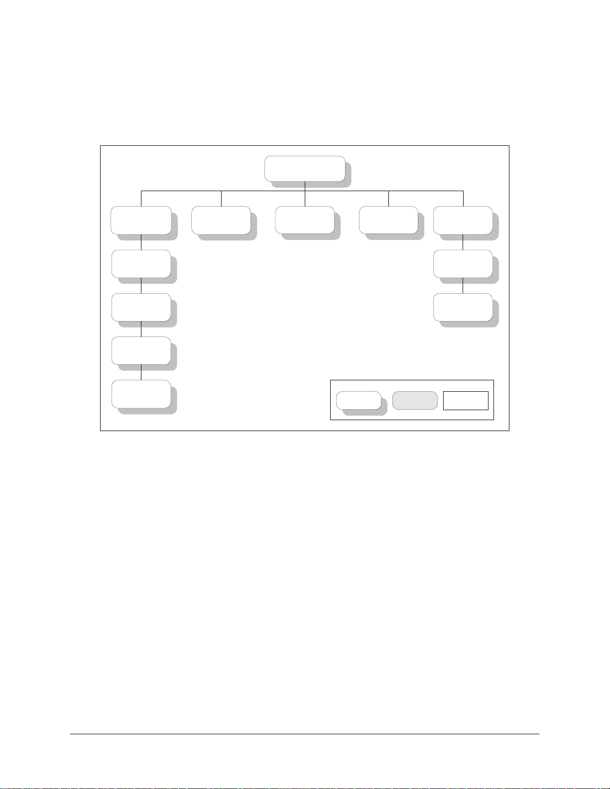
3.5 Menu System
To access and execute all functions, refer to Figure 3-3 through Figure 3-12. Use the
main menu in Figure 3-3 as a quick reference for accessing the 1:1 switch functions. For
further configuration details, refer to Section 3.2.
When the 1:1 switch power is turned ON, the base level of the menu system displays the
sign-on message:
Line 1 of the sign-on message is the 1:1 switch model number and type.
•
Line 2 is the version number of the firmware.
•
The main level of the menu system is Function Select. To access this level from the
sign-on message, press the [←] or [→] keys. From the Function Select menu, select one
of the functional categories:
Configuration
•
Monitor
•
Faults/Alarms
•
Stored Faults/Alarms
•
Utility
•
Press [←] or [→] to move from one selection to another. When line 2 displays the
desired function, select that level by pressing [ENTER]. After entering the appropriate
functional level, press [←] or [→] to move to the desired function.
To view or change the configuration of the 1:1 switch, enter the Configuration level from
the Function Select menu. Once in the Configuration menu, press [←] or [→] to scroll
through the Configuration menu selection.
Press [ENTER] to select the desired Configuration menu option. To view the options for
the selected configuration parameters, press [←] or [→]. To change a configuration
parameter, press [ENTER] to begin the change process.
Rev. 3 3-7
Page 46

Operation SMS-301 Redundancy Switch
Press [↑] or [↓] to change the parameters. After the display represents the correct
parameters, press [ENTER] to execute the change. This action initiates the necessary
programming by the 1:1 switch.
To undo a parameter change prior to execution, press [CLEAR].
The following notes describe each configuration function in detail.
Notes:
1. Figure 3-3 through Figure 3-12 list the front panel menu window selections.
2. Menus or commands that are specific to certain 1:1 switch configurations are
only accessible after selecting the appropriate 1:1 switch configuration. This
prevents incompatible parameters from accidentally being selected.
3-8 Rev. 3
Page 47
SMS-301 Redundancy Switch Operation
3.5.1 Front Panel Menus
SMS-301
VER: 1.1.7
FUNCTION SELECT
CONFIGURATION
CONFIGURATION
SWITCH CONTROL
(Figure 3-4)
CONFIGURATION
SYSTEM
(Figure 3-5)
CONFIGURATION
SAVE
(Figure 3-6)
CONFIGURATION
RECALL
(Figure 3-7)
FUNCTION SELECT
MONITOR
(Figure 3-8)
Figure 3-3. Main Menu
FUNCTION SELECT
FAULTS
(Figure 3-9)
Key:
ACCESS TO
SUBMENU
FUNCTION SELECT
STORED FAULTS
(Figure 3-10)
CONDITIONAL OR
OPTION-
DEPENDENT
FUNCTION SELECT
UTILITY
UTLITY SYSTEM
(Figure 3-11)
UTILITY MODEM
CONTROL
(Figure 3-12)
Parameter
Information
Rev. 3 3-9
Page 48

Operation SMS-301 Redundancy Switch
SMS-301
VER: X.X.X
OPERATION MODE
AUTOMATIC
MANUAL
ON-LINE DEMOD
A-DEMOD
B-DEMOD
(Independent and Manual
Mode only)
Figure 3-4. Configuration Switch Control Menu
FUNCTION SELECT
CONFIGURATION
ON-LINE MODEM
A-MODEM
B-MODEM
(Dependent and Manual
Mode only)
CONFIGURATION
SWITCH CONTROL
Key:
ACCESS TO
SUBMENU
ON-LINE MOD
A-MOD
B-MOD
(Independent and Manual
Mode only)
CONDITIONAL OR
OPTION-DEPENDENT
Parameter Information
3-10 Rev. 3
Page 49

SMS-301 Redundancy Switch Operation
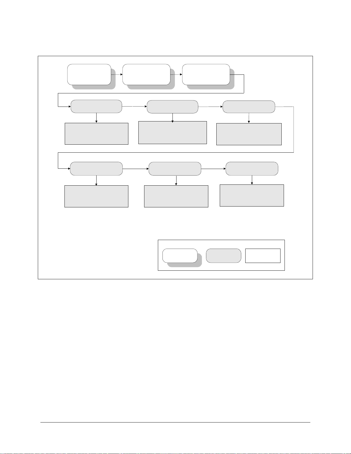
3.5.1.1 Configuration Switch Control Menu
Refer to Figure 3-4.
OPERATION MODE P rograms the 1:1 switch to AUTOMATIC or MANUAL mode.
Upon entry, the current status of the 1:1 switch is displayed. Press
[ENTER], then use any of the arrow keys to select. Press
[ENTER] to execute the change, or [CLEAR] to abandon the
change.
Note:
The AUTOMATIC mode is the normal operating mode.
The MANUAL mode is required for most configuration changes.
ON-LINE MODEM Select the prime or backup modem (A-MODEM or B-MODEM).
Note:
Ensure that the 1:1 switch is in MANUAL mode.
Upon entry, the current status of the 1:1 switch is displayed. Press
[ENTER], then use any of the arrow keys to select. Press
[ENTER] to execute the change, or [CLEAR] to abandon the
change.
Note:
This feature is available in the DEPENDENT and
MANUAL mode only.
ON-LINE MOD Select the prime or backup MODULATOR.
Note:
Ensure that the 1:1 switch is in MANUAL mode.
Upon entry, the current status of the 1:1 switch is displayed. Press
[ENTER], then use any of the arrow keys to select. Press
[ENTER] to execute the change, or [CLEAR] to abandon the
change.
Note:
This feature is available in the INDEPENDENT and
MANUAL mode only.
ON-LINE DEMOD In the ON-LINE DEMODULATOR, the operator can select a
prime or backup demodulator.
Note:
Ensure 1:1 switch is in MANUAL mode.
Upon entry, the current status of the 1:1 switch is displayed. Press
[ENTER], then use any of the arrow keys to select. Press
[ENTER] to execute the change, or [CLEAR] to abandon the
change.
Note:
This feature is available in the INDEPENDENT and
MANUAL mode only.
Rev. 3 3-11
Page 50
Operation SMS-301 Redundancy Switch
SMS-301
VER: X.X.X
SWITCH MODE
INDEPENDENT
DEPENDENT
(Change in Manual mode only)
DEMODULATOR DELAY
0.0 to 127.0 seconds,
in 0.5 second increments.
(Change in Independent
mode only)
FUNCTION SELECT
CONFIGURATION
CONFIGURATION
SYSTEM
MODEM DELAY
0.0 to 127.0 seconds,
in 0.5 second increments.
(Change in Dependent mode only)
MODULATORS
ACTIVE
IN-ACTIVE
(Change in Manual mode only)
MODULATOR DELAY
0.0 to 127.0 seconds,
in 0.5 second increments.
(Change in Independent
mode only)
DEMODULATORS
ACTIVE
IN-ACTIVE
(Change in Manual mode only)
Key:
ACCESS TO
SUBMENU
CONDITIONAL OR
OPTION-DEPENDENT
Figure 3-5. Configuration System Menu
Parameter Information
3-12 Rev. 3
Page 51

SMS-301 Redundancy Switch Operation
3.5.1.2 Configuration System Menu
Refer to Figure 3-5 for the Configuration System.
SWITCH MODE Programs the 1:1 switch to INDEPENDENT or DEPENDENT mode.
DEPENDENT
faults, the prime system will go off-line. The backup system
(modulator and demodulator) will come on-line.
INDEPENDENT
demodulator) faults, the backup component (modulator or
demodulator) will come on-line.
Note:
Ensure 1:1 switch is in MANUAL mode.
Upon entry, the current status of the 1:1 switch is displayed. Press
[ENTER], then use any of the arrow keys to select. Press [ENTER] to
execute the change, or [CLEAR] to abandon the change.
MODEM DELAY Programs a switching delay of 0 to 127 seconds, in 0.5 second
increments.
Note:
Ensure 1:1 switch is in DEPENDENT mode
Upon entry, the current status of the 1:1 switch is displayed. Press
[←] or [→] to move the flashing cursor. Press [↑] or [↓] to increase
or decrease the numbers. Press [ENTER] to execute the change, or
[CLEAR] to abandon the change.
MODULATOR DELAY Programs a switching delay of 0 to 127 seconds, in 0.5 second
increments.
Note:
Ensure 1:1 switch is in INDEPENDENT mode
Upon entry, the current status of the 1:1 switch is displayed. Press
[←] or [→] to move the flashing cursor. Press [↑] or [↓] to increase
or decrease the numbers. Press [ENTER] to execute the change, or
[CLEAR] to abandon the change.
DEMODULATOR
DELAY
Programs a switching delay of 0 to 127 seconds, in 0.5 second
increments.
— If a prime component (modulator or demodulator)
— If a prime component (modulator or
Note:
Ensure 1:1 switch is in INDEPENDENT mode
Upon entry, the current status of the 1:1 switch is displayed. Press
[←] or [→] to move the flashing cursor. Press [↑] or [↓] to increase
or decrease the numbers. Press [ENTER] to execute the change, or
[CLEAR] to abandon the change.
MODULATORS Programs the modulators to ACTIVE or INACTIVE.
Note:
Ensure 1:1 switch is in MANUAL mode.
Upon entry, the current status of the 1:1 switch is displayed. Press
[ENTER], then use any of the arrow keys to select. Press [ENTER] to
execute the change, or [CLEAR] to abandon the change.
DEMODULATORS Programs the demodulators to ACTIVE or INACTIVE.
Rev. 3 3-13
Page 52

Operation SMS-301 Redundancy Switch
Note:
Ensure 1:1 switch is in MANUAL mode.
Upon entry, the current status of the 1:1 switch is displayed. Press
[ENTER], then use any of the arrow keys to select. Press [ENTER] to
execute the change, or [CLEAR] to abandon the change.
3-14 Rev. 3
Page 53

SMS-301 Redundancy Switch Operation
SMS-301
VER: X.X.X
CONFIGURATION #X
SAVE
FUNCTION SELECT
CONFIGURATION
Key:
X = 1, 2, 3, 4, or 5.
Figure 3-6. Configuration Save Menu
3.5.1.3 Configuration Save Menu
Refer to Figure 3-6.
CONFIGURATION #X
SAVE
X = 1, 2, 3, 4, or 5.
Provides five memory locations for configurations to be saved into on
the M&C.
ACCESS TO
SUBMENU
CONFIGURATION
SAVE
CONDITIONAL OR
OPTION-DEPENDENT
Parameter Information
Press [ENTER], t hen use any of the arrow keys to select the desired
memory location. Press [ENTER] to execute the save, or [CLEAR] to
abandon the save.
Rev. 3 3-15
Page 54

Operation SMS-301 Redundancy Switch
SMS-301
VER: X.X.X
CONFIGURATION #X
RECALL
FUNCTION SELECT
CONFIGURATION
Key:
X = 1, 2, 3, 4, or 5.
Figure 3-7. Configuration Recall Menu
3.5.1.4 Configuration Recall Menu
Refer to Figure 3-7.
CONFIGURATION #X
RECALL
X = 1, 2, 3, 4, or 5.
Allows the recall of configurations that were previously saved on the
M&C.
ACCESS TO
SUBMENU
CONFIGURATION
RECALL
CONDITIONAL OR
OPTION-DEPENDENT
Parameter Information
Press [ENTER], t hen use any of the arrow keys to select the desired
memory location. Press [ENTER] to execute the recall, or [CLEAR]
to abandon the recall.
3-16 Rev. 3
Page 55

SMS-301 Redundancy Switch Operation
SMS-301
VER: X.X.X
MOD MM X-ONLINE
DMD DD Y-ONLINE
MM = A and B,
Modulators Active.
DD = A and B,
Demodulators Active.
X = A or B, Modulator Online.
Y = A or B, Demodulator Online.
Status only.
3.5.1.5 Monitor Menu
Refer to Figure 3-8.
MOD MM X–ONLINE
DMD DD Y–ONLINE
FUNCTION SELECT
MONITOR
Key:
ACCESS TO
SUBMENU
CONDITIONAL OR
OPTION-DEPENDENT
Figure 3-8. Monitor Menu
(Status Only.)
Line 1 displays summary of active prime modems and online
backup modems.
Line 2 displays summary of active prime and online backup
demodulators.
Parameter Information
Where:
MM = A and B, indicates modulators are active.
If not active, an “_” is displayed.
DD = A and B, indicates demodulators are active.
If not active, an “_” is displayed.
X = A or B, indicates modulator A or B online.
Y = A or B, indicates demodulators A or B online.
Rev. 3 3-17
Page 56

Operation SMS-301 Redundancy Switch
SMS-301
VER: X.X.X
OPERATIONAL
++
MOD ONLINE
DMD ONLINE
Key:
ACCESS TO
SUBMENU
FUNCTION SELECT
FAULTS/ALARMS
BATTERY/CLOCK
+12 VOLT SUPPLY
+5 VOLT SUPPLY
PWR SUPPLY #1
PWR SUPPLY #2
MODEM COM LINK
DEMOD VERIFY
INTERFACE MODULE
CONDITIONAL OR
OPTION-DEPENDENT
COMMON
------+---
CONTROLLER
MOD VERIFY
Parameter Information
Figure 3-9. Faults/Alarms Menu
3-18 Rev. 3
Page 57

SMS-301 Redundancy Switch Operation
3.5.1.6 Faults/Alarms
Refer to Figure 3-9.
The Faults/Alarms level is accessible from the Function Select menu. Press [←] or [→]
to move between the following Faults/Alarms groups:
OPERATIONALX(Status Only)
X = 0 through 9.
Displays the fault status of the currently selected on-line modulator and
demodulator.
When a fault is present, the date and time of the fault is displayed alternately.
COMMON
(Status Only)
Note: Date and time faults are also displayed.
Use [←] or [→] to display faults within the 1:1 switch, such as the following:
Battery Clock - Battery or clock fault.
•
+12V Supply - +12V supply fault.
•
+5V Supply - +5V supply fault
•
Power Supply #1 - Power supply #1 fault.
•
Power Supply #2 - Power supply #2 fault.
•
Controller - Controller power ON/OFF cycle fault.
•
Modem COMM Link - Modem communications fault.
•
Modem Verify- Prime and backup modems do not match.
•
DEMOD Verify - Prime and backup DEMODS do not match.
•
Interface Module - Interface module is missing or will not program
•
fault.
Rev. 3 3-19
Page 58

Operation SMS-301 Redundancy Switch
SMS-301
VER: X.X.X
OPERATIONAL
++
MOD ONLINE
DMD ONLINE
FUNCTION SELECT
STORED FLTS/ALMS
COMMON
------+---
BATTERY/CLOCK
+12 VOLT SUPPLY
+5 VOLT SUPPLY
PWR SUPPLY #1
PWR SUPPLY #2
CONTROLLER
MODEM COM LINK
MOD VERIFY
DEMOD VERIFY
INTERFACE MODULE
CLEAR ??
STORED FAULTS
Press [ENTER] twice to clear
stored faults.
Key:
ACCESS TO
SUBMENU
OPTION-DEPENDENT
Figure 3-10. Stored Faults/Alarms Menu
CONDITIONAL OR
Parameter Information
3-20 Rev. 3
Page 59

SMS-301 Redundancy Switch Operation
3.5.1.7 Stored Faults/Alarms
Refer to Figure 3-10.
OPERATIONAL X (Status Only)
X = 0 through 9.
Displays the fault status of the currently selected on-line modulator and
demodulator.
When a stored fault is present, the date and time of the fault will be displayed
alternately.
COMMON
CLEAR??
STORED FAULTS
(Status Only)
Note:
Date and time of faults also are displayed.
Press [←] or [→] to display faults within the 1:1 switch, such as the following:
Battery Clock - Battery or clock fault.
•
+12V Supply - +12V supply fault.
•
+5V Supply - +5V supply fault
•
Power Supply #1 - Power supply #1 fault.
•
Power Supply #2 - Power supply #2 fault.
•
Controller - Controller power ON/OFF cycle fault.
•
Modem COMM Link - Modem communications fault.
•
Modem Verify- Prime and backup modems do not match.
•
DEMOD Verify - Prime and backup DEMODS do not match.
•
Interface Module - Interface module is missing or will not program
•
fault.
Allows the operator to clear all stored faults within the memory of the 1:1 switch.
Press [ENTER], then ‘YES’ is displayed. Press [ENTER] to confirm clearing all
stored faults, or press [CLEAR] to exit without clearing stored faults.
Rev. 3 3-21
Page 60
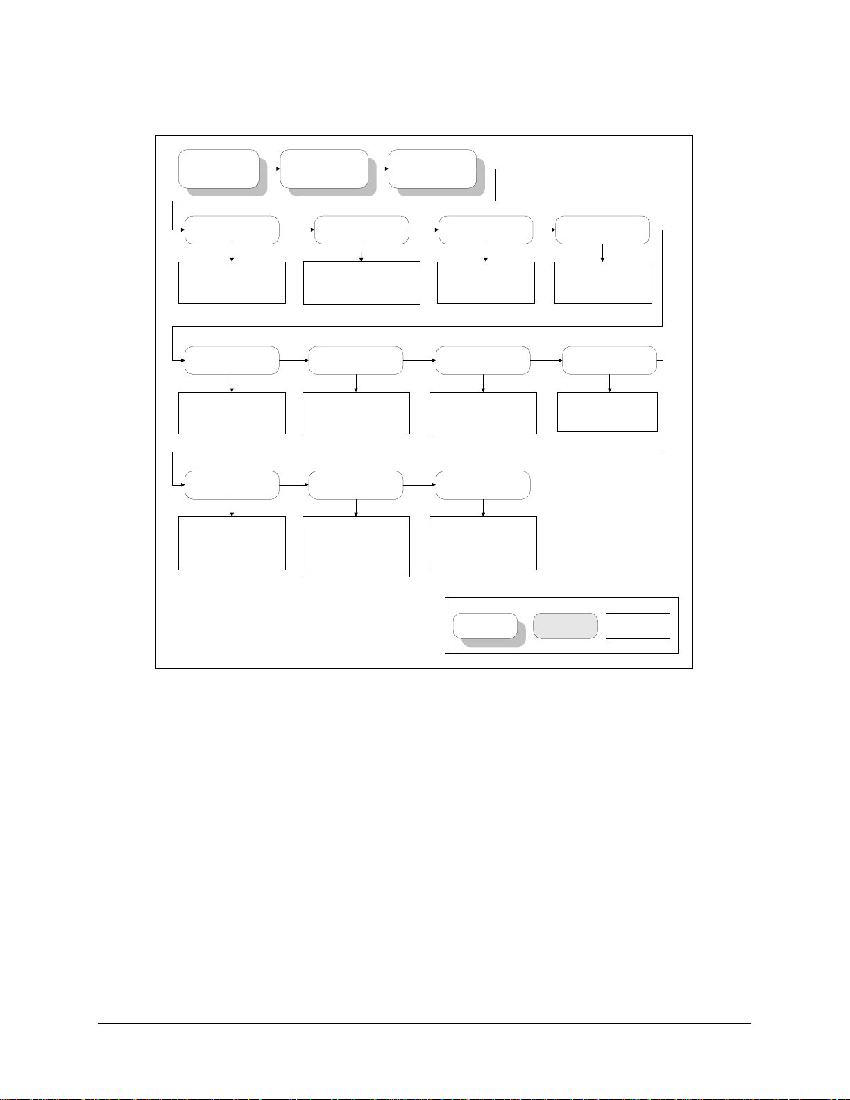
Operation SMS-301 Redundancy Switch
SMS-301
VER: X.X.X
TIME: 12:00:00AM
DATE: 12/12/97
Current time: HH:MM:SS AM
Current date: MM/DD/YY
LAMP TEST ??
PRESS ENTER
Illuminates all front panel LEDs
for three seconds
M&C FIRMWARE
FW/NNNNNN-DDR
NNNNNN = Number
DD = Dash Number
R = Revision Number
Press [ENTER] to view date of
M&C firmware.
FUNCTION SELECT
UTILITY
REMOTE BAUD RATE
Baud rate:150, 300, 600, 1200,
2400, 4800, 9600, 19200
Parity: EVEN, ODD, or NONE.
DISPLAY CONTRAST
LEVEL: 64
Sets the display contrast level
as desired, from 0 to 100.
BOOT FIRMWARE
FW/NNNNNN-DDR
NNNNNN = Number
DD = Dash Number
R = Revision Number
Press [ENTER] to view date
and version number of Boot
firmware.
UTILITY SYSTEM
REMOTE ADDRESS
1 to 255
INTERFACE TYPE
Status only.
MASTER RESET
HARD/SOFT
SOFT
HARD
REMOTE TYPE
RS232
RS485 (2-WIRE)
RS485 (4-WIRE)
POWER SUPPLY
1 ACTIVE
2 ACTIVE
1&2 ACTIVE
Key:
ACCESS TO
SUBMENU
Figure 3-11. Utility System Menu
CONDITIONAL OR
OPTION-DEPENDENT
Parameter Information
3-22 Rev. 3
Page 61

SMS-301 Redundancy Switch Operation
3.5.1.8 Utility System
Refer to Figure 3-11.
TIME: HH:MM:SS AM
DATE: MM/DD/YY
REMOTE BAUD RATE The parity and baud rate settings of the 1:1 switch are
REMOTE ADDRESS The current 1:1 switch address is displayed (1 to 255).
Time of day and date display/set function.
To change the time and/or date:
Note:
Ensure 1:1 switch is in MANUAL mode.
Press [←] or [→] to position the cursor over the parameter to
be changed. Pr ess [↑] or [↓] to change the p arameter. Once the
parameters are set as desired, press [ENTER] to set the time
and date.
displayed.
To change the baud rate and/or parity, perform the following:
Note:
Ensure 1:1 switch is in MANUAL mode.
The available baud rates are as follows: 150, 300, 600, 1200,
2400, 4800, 9600, or 19200 bps. Baud rates are set by pressing
[ENTER], and then [↑] or [↓] to select the desired rate. Press
[ENTER] to accept the change, or [ C LEAR] to abandon the
change.
The parity can be set to EVEN, ODD, or NONE, by pressing
[ENTER], [→] to place the cursor on th e parity setting, and
then [↑] or [↓] to select the desired setting. Press [ENTER] to
accept the change, o r [CLEAR] to abandon the change.
To change the remote address, press [ENTER], then [←] or
[→] to position the cursor over the parameter to be changed.
Press [↑] or [↓] to change the p arameter, then press [ENTER]
to accept the change, or [CLEAR] to abandon the change.
Note:
A 0 address is reserved for global use only.
REMOTE TYPE Displays the current remote type: EIA-232, EIA-485 (2-Wire),
or EIA-485 (4-Wire).
To change the remote type, press [ ENTER], then any of the
arrow keys to select the desired remote type. Press [ENTER]
to accept the change, or [CLEAR] to abandon the change.
LAMP TES T ??
PRESS ENTER
Rev. 3 3-23
Lamp test function. Press [ENTER] to turn all front panel LED
indicators ON for 3 seconds.
Page 62

Operation SMS-301 Redundancy Switch
DISPLAY CONTRAST Sets the display contrast setting, as desired.
Note:
Ensure 1:1 switch is in MANUAL mode.
To change the display cont rast , press [ENTER], then [←] or
[→] to position the cursor over the parameter to be changed.
Press [↑] or [↓] to change the p arameter, then press [ENTER]
to accept the change, or [CLEAR] to abandon the change.
INTERFACE TYPE (Status Only)
Displays the currently installed in terface type, as follows:
50-Pin 25-Pin (V.35)
37-Pin 37-Pin (LVDS)
25-Pin (EIA-232) 37-Pin (EIA-422)
25-Pin (EIA-530)
POWER SUPPLY Displays the currently selected power supply (1 ACTIVE,
2 ACTIVE, or 1&2 ACTIVE).
To change the power supply setting, press [ENTER], then any
of the arrow keys to select the desired setting. Press [ENTER]
to accept the change, or [CLEAR] to abandon the change.
M&C FIRMWARE Displays the M&C firmware version number. Press [ENTER]
to display the date of the M&C firmware.
BOOT FIRMWARE Displays the BOOT firmware version number. Press [ENTER]
to display the date of the BOOT firmware.
MASTER RESET
Master reset function (SOFT or HARD).
HARD/SOFT
CAUTION
Initiating a HARD reset will reset the 1:1 switch and place the
default configuration settings in ROM. Initiating a SOFT reset
will reset the 1:1 switch hardware, but saves the current
configuration settings.
To perform a master reset, press [ENTER], any of the arrow
keys to select the type, then pr ess [ENTER] again. Press [→]
five times to position the cursor on YES. Press [ENTER] to
confirm the reset type and execute the reset, or [CLEAR] to
change reset type and/or abandon the reset.
Note:
The following parameters do not revert to default
settings after a hard reset:
Address
Parity
Baud Rate
Remote Type
Display Contrast
3-24 Rev. 3
Page 63

SMS-301 Redundancy Switch Operation
This page is intentionally left blank.
Rev. 3 3-25
Page 64

Operation SMS-301 Redundancy Switch
SMS-301
VER : X.X.X
AUTOMATIC VERIFY
ENABLE
DISABLE
MODEM B ADDRESS
1 to 255.
FUNCTION SELECT
UT IL IT Y
LOA D M O D EM
A->B
Pr es s [E N TER ] t w ic e to cop y
Modem A configuration to Modem
B.
MODEM BAUD RATE
9600
19200
UT IL IT Y
MODEM CONTR OL
Pr es s [E N TER ] t w ic e to
configuration to Modem A.
REV EMULATION
CURRENT_VERSION
LOA D M O D EM
B->A
copy Modem B
Status only.
Key:
ACCESS TO
SUBMENU
CONDITIONAL OR
OPTION-DEPENDENT
Figure 3-12. Utility Modem Control Menu
MODEM A ADDRESS
1 to 255.
Para m e ter Info rm at ion
3-26 Rev. 3
Page 65

SMS-301 Redundancy Switch Operation
3.5.1.9 Utility Modem Control
Refer to Figure 3-12.
AUTOMATIC VERIFY Selects ENABLE or DISABLE for automatic verify feature.
To change the setting, press [ENTER], then use any of the arrow keys
to select. Press [ ENTER] to accept the change, or [CLEAR] t o abandon
the change.
LOAD MODEM A → B
LOAD MODEM B → A
MODEM A ADDRESS Selects an address from 1 to 255 for Modem A.
Copies Modem A configuration to Modem B.
To perform the copy function, press [ENTER] twice.
Copies Modem B configuration to Modem A.
To perform the copy function, press [ENTER] twice.
To change the address for Mo dem A, press [ENTER], then [←] or [→]
to position the cursor over the parameter to be changed. Press [↑] or [↓]
to change the parameter, then press [ENTER] to accept the change, o r
[CLEAR] to abandon the change.
Note:
A 0 address is reserved for global use only.
MODEM B ADDRESS Selects an address for Modem B.
To change the address for Modem B, press [ENTER], then [←] or [→]
to position the cursor over the parameter to be changed. Press [↑] or [↓]
to change the parameter, then press [ENTER] to accept the change, o r
[CLEAR] to abandon the change.
Note:
A 0 address is reserved for global use only.
MODEM BAUD RATE Selects the modem baud rate (9600 or 19200 bit/s).
To change the modem baud rate, p r ess [ENTER], then an y of the arrow
keys to select. Press [ENTER] to accept the change, or [CLEAR] to
abandon the change.
Rev. 3 3-27
Page 66

Operation SMS-301 Redundancy Switch
REV EMULATION Programs an emulation mode of the previous functional revision. This
allows the operator to select the CURRENT VERSION or
FUNCTIONAL X:
Note:
The number displayed in the CURRENT VERSION position
increases with each software version change.
Upon entry, the CURRENT VERSION is displayed. Press [↑] or [↓] to
select the FUNCTIONAL version. Press [ENTER] to execute the
change.
Notes:
1. Programming a current version (defaul t) allows all features and
options (if installed) to operate normally.
2. Programming a FUNCTIONAL version (X) eliminates any changes
that affect the later version. On l y functional changes are affected by
the revision emulation feature.
3. A correction change (e.g., V ER 1.1.1) remains fixed in acco rdance
with the latest version. Since the revision emulation default is the
current version, program the functional version at the start of each
operation.
4. The revision emulation featur e does not affect some interface
changes for the direct operation of the modem (Configuration
Save/Recall, test mode screen in the Utility/System, all factory setup
modes, etc.).
3-28 Rev. 3
Page 67

Chapter 4.
THEORY OF OPERATION
4
This chapter provides the basic theory of operation for the following:
M&C 75
•
M&C 50
•
IBS, IDR, ASYNC, D&I, 50-pin (PL/5951)
•
EIA-422/-449, V.35, G.703, 37-pin (PL/5952)
•
LVDS/DVB-TX, 37-pin (PL/6201-1)
•
EIA-422/DVB-TX, 37-pin (PL/6201-2)
•
EIA-232/-422/-530, V.35, G.703 25-pin (PL/6026)
•
Remote Switch Option (RS-301), 100-pin (PL6592/6627)
•
Ω
Ω
4.1 Monitor and Control (M&C)
The M&C monitors the switch configuration, as well as 1:1 switch and modem faults and
status. 1:1 switch configuration parameters are stored in battery-backed RAM to provide
total recovery after a power-down. The 1:1 switch gathers status and provides extensive
fault monitoring. A local front panel interface and a remote communications interface
provide user access to all 1:1 switch functions.
Rev. 3 4-14-1
Page 68

Theory of Operation SMS-301 Redundancy Switch
4.1.1 Theory of Operation
The M&C module uses an Intel 80C32 microcontroller operating at 11.0592 MHz. The
microsystem supports 256 kbit/s of FLASH memory for code and data.
Memory-mapped I/O includes:
Real time clock/memory
•
8-channel analog-to-digital converter
•
External buffered bus structure for overall 1:1 switch control and status gathering.
•
The 80C32 microcontroller supports a serial, asynchronous, remote control (J10)
communications channel (EIA-232 or EIA-485) with a maximum baud rate of 19200 bit/s.
The modem control interface (J13) is an EIA-485 serial communication link which allows
the 1:1 switch to monitor and configure the attached modems.
A lithium battery maintains the system real time clock and 1:1 switch configuration
through power-down situations.
The M&C motherboard interfaces and controls a variety of data interface connector
switch boards. The customer-application dictates the type of connector switch board to be
installed within the 1:1 switch.
4-2 Rev. 3
Page 69

SMS-301 Redundancy Switch Theory of Operation
4.2 SMS-301 Data Interface
4.2.1 IBS, IDR, ASYNC, or D&I (J1, J2, J3), 50-Pin (PL/5951)
The applications for this board are IDR, IBS, ASYNC, or D&I format data. The board
consists of three 50-pin data I/O connectors, interface, and switching electronics. There
are no configuration jumpers on the 50-pin board.
The interface to the M&C motherboard is via a 40-pin connector located along one side of
the board. The board, under M&C control, will switch data between the prime modem
(J2), and/or the backup modem (J3), and the common customer-data interface (J1).
The M&C automatically detects the type of board installed and presents this information,
via the front panel display, under Interface Type in the Utility System menu.
4.2.2 EIA-422/-449, G.703, or V.35 (J1, J2, J3), 37-Pin (PL/5952)
The applications for this board are EIA-422/-449, G.703 or V.35 format data. The board
consists of three 37-pin data I/O connectors, interface, and switching electronics.
The interface to the M&C motherboard is via a 40-pin connector located along one side of
the board. The board, under M&C control, will switch data between the prime modem
(J2), and/or the backup modem (J3), and the common customer-data interface (J1).
The M&C automatically detects the type of switch board installed and presents this
information, via the front panel display, under Interface Type in the Utility System menu.
4.2.3 LVDS-DVB TX, (J1, J2, J3), 37-Pin, (PL/6201-1)
There are no configuration jumpers on the LVDS board. The current version of this board
is for the SDM-2020 Satellite Modulator only. The intended signal flow path is from the
customer-connection on J1 to the switched equipment on J2 and J3.
In the powered down state, this board provides an unbuffered signal path from J1 to J2.
When power is available to the board, the signals from J1 to J2 and J3 are buffered.
Rev. 3 4-3
Page 70

Theory of Operation SMS-301 Redundancy Switch
4.2.4 EIA-422/DVB TX (J1, J2, J3), 25-Pin (PL/6026)
The applications for this switch board are EIA-232, EIA-422, or V.35 format data. The
switch board consists of three 25-pin data I/O connectors, interface, and switching
electronics.
The interface to the M&C motherboard is via a 40-pin connector located along one side of
the switch board. The switch board, under M&C control, will switch data between the
prime modem (J2), and/or the backup modem (J3), and the common customer-data
interface (J1).
The M&C automatically detects the type of switch board installed and presents this
information, via the front panel display, under Interface Type in the Utility System menu.
4-4 Rev. 3
Page 71

SMS-301 Redundancy Switch Theory of Operation
4.3 Remote Switch (RS-301) Option
The application for this option is to provide access to tributary data, via the remote
switch, when the 1:1 switch is used with two SDM-300/-300A Satellite Modems that are
configured for the 8-Channel MUX option.
For this option an extender board (AS/6542) replaces the switch board that normally
resides within the 1:1 switch. This extender board interfaces with the M&C motherboard
and provides control signals, power and ground to an external data switch (RS-301).
The remote switch (RS-301) provides the user with connections for eight tributary
channels (EIA-422, EIA-232 data and clock) and one connection for auxiliary data. This
switch, under M&C control, will switch data (only) between the prime modem and/or the
backup modem, and the customer-data interface. The TX IF switching remains internal to
the 1:1 switch.
The M&C automatically detects this switch option and presents this information, via the
front panel display, under Interface Type in the Utility System menu.
The connectors for the remote switch are listed in Table 4-1.
Table 4-1. Remote Switch (RS-301) Connectors
Name REF DES Connector Type Function Table Reference
TRIBUTA R Y 1 DATA J1 15-pin D EIA -422 or EIA-232
TRIB 1 Clock and D a ta
TRIBUTA R Y 2 DATA J2 15-pin D EIA -422 or EIA-232
TRIB 2 Clock and D a ta
TRIBUTA R Y 3 DATA J3 15-pin D EIA -422 or EIA-232
TRIB 3 Clock and D a ta
TRIBUTA R Y 4 DATA J4 15-pin D EIA -422 or EIA-232
TRIB 4 Clock and D a ta
TRIBUTA R Y 5 DATA J5 15-pin D EIA -422 or EIA-232
TRIB 5 Clock and D a ta
TRIBUTA R Y 6 DATA J6 15-pin D EIA -422 or EIA-232
TRIB 6 Clock and D a ta
TRIBUTA R Y 7 DATA J7 15-pin D EIA -422 or EIA-232
TRIB 7 Clock and D a ta
TRIBUTA R Y 8 DATA J8 15-pin D EIA -422 or EIA-232
TRIB 8 Clock and D a ta
AUX J9 15-pin D A ux ilia ry Data Table 4-10
MODEM A DAT A J14 100-pin Miniature D Modem A Data I /O Table 4-11
MODEM B DATA J15 100-pin Miniature D Modem B Data I/O Table 4-12
SWITCH CONTROL
INTERFACE
J16 37-pin D Control Signals, Power and
Ground
Table 4-2
Table 4-3
Table 4-4
Table 4-5
Table 4-6
Table 4-7
Table 4-8
Table 4-9
Table 4-13
Rev. 3 4-5
Page 72

Theory of Operation SMS-301 Redundancy Switch
Table 4-2. Tributary 1 Data (J1)
Pin No. Name Function
1 CTS422A1 EIA-422, Clear-to-Se nd A (-)
2, 5, 11 GND Ground
3 TC422B-1 EIA-422, TX Clock B (+)
4 TD422A-1 EIA-422 TX Data A (-)
6 TD232-1 EIA-232 TX Data
9 CTS422B1 EIA-422 Clear-to-Send B (+)
10 TC422A-1 EIA-422 TX Clock A (-)
12 TD422B-1 EIA-422 TX Clock B (+ )
13 CTS232-1 EIA- 232 Cl e a r- to- Se nd
14 TC232-1 EIA-232 TX Clock
Table 4-3. Tributary 2 Data (J2)
Pin No. Name Function
1 CTS422A2 EIA-422, Clear-to-Se nd A (-)
2, 5, 11 GND Ground
3 TC422B-2 EIA-422, TX Clock B (+)
4 TD422A-2 EIA-422 TX Data A (-)
6 TD232-2 EIA-232 TX Data
9 CTS422B2 EIA-422 Clear-to-Send B (+)
10 TC422A-2 EIA-422 TX Clock A (-)
12 TD422B-2 EIA-422 TX Clock B (+ )
13 CTS232-2 EIA- 232 Cl e a r- to- Se nd
14 TC232-2 EIA-232 TX Clock
Table 4-4. Tributary 3 Data (J3)
Pin No. Name Function
1 CTS422A3 EIA-422, Clear-to-Se nd A (-)
2, 5, 11 GND Ground
3 TC422B-3 EIA-422, TX Clock B (+)
4 TD422A-3 EIA-422 TX Data A (-)
6 TD232-3 EIA-232 TX Data
9 CTS422B3 EIA-422 Clear-to-Send B (+)
10 TC422A-3 EIA-422 TX Clock A (-)
12 TD422B-3 EIA-422 TX Clock B (+ )
13 CTS232-3 EIA- 232 Cl e a r- to- Se nd
14 TC232-3 EIA-232 TX Clock
4-6 Rev. 3
Page 73

SMS-301 Redundancy Switch Theory of Operation
Table 4-5. Tributary 4 Data (J4)
Pin No. Name Function
1 CTS422A4 EIA-422, Clear-to-Se nd A (-)
2, 5, 11 GND Ground
3 TC422B-4 EIA-422, TX Clock B (+)
4 TD422A-4 EIA-422 TX Data A (-)
6 TD232-4 EIA-232 TX Data
9 CTS422B4 EIA-422 Clear-to-Send B (+)
10 TC422A-4 EIA-422 TX Clock A (-)
12 TD422B-4 EIA-422 TX Clock B (+ )
13 CTS232-4 EIA- 232 Cl e a r- to- Se nd
14 TC232-4 EIA-232 TX Clock
Table 4-6. Tributary 5 Data (J5)
Pin No. Name Function
1 CTS422A5 EIA-422, Clear-to-Se nd A (-)
2, 5, 11 GND Ground
3 TC422B-5 EIA-422, TX Clock B (+)
4 TD422A-5 EIA-422 TX Data A (-)
6 TD232-5 EIA-232 TX Data
9 CTS422B5 EIA-422 Clear-to-Send B (+)
10 TC422A-5 EIA-422 TX Clock A (-)
12 TD422B-5 EIA-422 TX Clock B (+ )
13 CTS232-5 EIA- 232 Cl e a r- to- Se nd
14 TC232-5 EIA-232 TX Clock
Table 4-7. Tributary 6 Data (J6)
Pin No. Name Function
1 CTS422A6 EIA-422, Clear-to-Se nd A (-)
2, 5, 11 GND Ground
3 TC422B-6 EIA-422, TX Clock B (+)
4 TD422A-6 EIA-422 TX Data A (-)
6 TD232-6 EIA-232 TX Data
9 CTS422B6 EIA-422 Clear-to-Send B (+)
10 TC422A-6 EIA-422 TX Clock A (-)
12 TD422B-6 EIA-422 TX Clock B (+ )
13 CTS232-6 EIA- 232 Cl e a r- to- Se nd
14 TC232-6 EIA-232 TX Clock
Rev. 3 4-7
Page 74

Theory of Operation SMS-301 Redundancy Switch
Table 4-8. Tributary 7 Data (J7)
Pin No. Name Function
1 CTS422A7 EIA-422, Clear-to-Se nd A (-)
2,5,11 GND Ground
3 TC422B-7 EIA-422, TX Clock B (+)
4 TD422A-7 EIA-422 TX Data A (-)
6 TD232-7 EIA-232 TX Data
9 CTS422B7 EIA-422 Clear-to-Send B (+)
10 TC422A-7 EIA-422 TX Clock A (-)
12 TD422B-7 EIA-422 TX Clock B (+ )
13 CTS232-7 EIA- 232 Cl e a r- to- Se nd
14 TC232-7 EIA-232 TX Clock
Table 4-9. Tributary 8 Data (J8)
Pin No. Name Function
1 CTS422A8 EIA-422, Clear-to-Se nd A (-)
2,5,11 GND Ground
3 TC422B-8 EIA-422, TX Clock B (+)
4 TD422A-8 EIA-422 TX Data A (-)
6 TD232-8 EIA-232 TX Data
9 CTS422B8 EIA-422 Clear-to-Send B (+)
10 TC422A-8 EIA-422 TX Clock A (-)
12 TD422B-8 EIA-422 TX Clock B (+ )
13 CTS232-8 EIA- 232 Cl e a r- to- Se nd
14 TC232-8 EIA-232 TX Clock
Table 4-10. AUX Data (J9)
Pin No. Name Function
1 MCA TX Aggregate Clock
2,5,11 GND Ground
3 RT-B EIA-422, RX Tim i ng B ( + )
4 RD-A EIA-422, RX Data A (-)
6 RR-B RX Ready B (+)
7 N/C No Connection
8 MF MOD Fault
9 MCB TX Aggregate Data
10 RT-A EIA-422, RX Timing A (- )
12 RD-B EIA-422, RX Data B (+ )
13 RR-A RX Ready A (-)
14 N/C No Connection
15 DF DEMOD Fault
4-8 Rev. 3
Page 75

SMS-301 Redundancy Switch Theory of Operation
Table 4-11. Modem A Data (J14)
Pin # Circuit Description Pin # Circuit Description
1 - N/A 51 GND GROUND
2 - N/A 52 A_TC232_5 EIA-232, TX CL K, TRI B 5
3 - N/A 53 A_TD232_5 EIA- 232, TX DAT, T R IB 5
4 - N/A 54 A_CTS232_5 EI A-232, CTS, TRIB 5
5 GND GROUND 55 A_TD422B_5 EIA-422, T X D ATB (+), T RIB 5
6 GND GROUND 56 A_TD422A_5 EI A-422, TX DATA (-), TRI B 5
7 /A_DF DEMOD FAULT 57 A_TC422B_5 EIA-422, TX CL KB (+), TRIB 5
8 /A_MF MOD FAU LT 58 A_T C422A_5 EIA-422, TX CLKA (-), TRI B 5
9 GND GROUND 59 A_CTS422B5 EIA-422, CTS B ( +) , TRIB 5
10 A_RT+B RECEIVE TIMING B (+) 60 A_CTS422A5 EIA-422, CTSA (-), TRI B 5
11 A_RT-A RECEIVE TIMI NG A (-) 61 GND GROUND
12 GND GROUND 62 A_TC232_4 EIA-232, TX CLK, TRIB 4
13 A_RD+B RECEIVE DATA B (+) 63 A_TD232_4 EIA-232, TX DAT, TRIB 4
14 A_RD-A RECEIVE D ATA A ( - ) 64 A_CTS232_4 EIA-232, CTS , TRIB 4
15 GND GROUND 65 A_TD422B_4 EIA-422, TX D ATB (+), T RIB 4
16 A_RR+B RECEIVER REA D Y B ( +) 66 A_TD422A_4 EIA-422, TX DATA (-), TRIB 4
17 A_RR-A RECEIVER READY A (-) 67 A_TC422B_4 EIA- 422, TX CLK B ( +) , TRIB 4
18 GND GROUND 68 A_TC422A_4 EIA-422, TX CLKA (-), TRIB 4
19 A_MCB MASTER CLOCK B 69 A_CT S422B4 EIA-422, CTSB (+), TRIB 4
20 A_MCA MASTER CLOCK A 70 A_CTS422A4 EIA-422, CTSA (-), TRIB 4
21 GND GROUND 71 GND GROUND
22 A_TC232_8 EIA-232, TX CLK, TRIB 8 72 A_TC232_3 EIA-232 ,TX CLK, TRIB 3
23 A_TD232_8 EIA-232, T X D AT, TRIB 8 73 A_TD232_3 EIA-232, T X D AT, TRIB 3
24 A_CTS232_8 EIA-232, CTS, TRIB 8 74 A_CTS 232_3 EIA-232, CTS, TRI B
25 A_TD422B_8 EIA-422, TX DATB (+), T RIB 8 75 A_TD422B_3 EIA-422, TX DA TB (+), TRIB 3
26 A_TD422A_8 EIA - 422, TX DAT A (-), TRIB 8 76 A_TD422A_3 EIA-422, TX D ATA (-), TRIB 3
27 A_TC422B_8 EIA-422, TX CL KB (+), TRIB 8 77 A_TC422B_3 EIA-422, TX CLKB (+), TRIB 3
28 A_TC422A_8 EIA-422, TX CLKA (-), TRIB 8 78 A_TC422A_3 EI A-422, TX CLKA (-), TRI B 3
29 A_CTS422B8 EIA-422, CTSB (+) , TRIB 8 79 A_CTS422B3 EIA-422, CTSB (+), TR IB 3
30 A_CTS422A8 EIA- 422, CTSA (-), TRIB 8 80 A_CTS422A3 EIA- 422, CTSA (-), TRIB 3
31 GND GROUND 81 GND GROUND
32 A_TC232_7 EIA-232 ,TX CLK, TRIB 7 82 A_TC232_2 EIA-232, TX CLK, TRIB 2
33 A_TD232_7 EIA-232, T X D AT, TRI 7 83 A_TD232_2 EIA-232, T X D AT, TRIB 2
34 A_CTS232_7 EIA-232, CTS, TRIB 7 84 A_CTS 232_2 EIA-232, CTS, TRI B 2
35 A_TD422B_7 EIA-422, TX DATB (+), T RIB 7 85 A_TD422B_2 EIA-422, TX DA TB (+), TRIB 2
36 A_TD422A_7 EIA - 422, TX DAT A (-), TRIB 7 86 A_TD422A_2 EIA-422, TX D ATA (-), TRIB 2
37 A_TC422B_7 EIA-422, TX CL KB (+), TRIB 7 87 A_TC422B_2 EIA-422, TX CLKB (+), TRIB 2
38 A_TC422A_7 EIA-422, TX CLKA (-), TRIB 7 88 A_TC422A_2 EI A-422, TX CLKA (-), TRI B 2
39 A_CTS422B7 EIA-422, CTSB (+) , TRIB 7 89 A_CTS422B2 EIA-422, CTSB (+), TR IB 2
40 A_CTS422A7 EIA- 422, CTSA (-), TRIB 7 90 A_CTS422A2 EIA- 422, CTSA (-), TRIB 2
41 GND GROUND 91 GND GROUND
42 A_TC232_6 EIA-232, TX CLK, TRIB 6 92 A_TC232_1 EIA-232, TX CLK, TRIB 1
43 A_TD232_6 EIA-232, T X D AT, TRIB 6 93 A_TD232_1 EIA-232, T X D AT, TRIB 1
44 A_CTS232_6 EIA-232, CTS, TRIB 6 94 A_CTS 232_1 EIA-232, CTS, TRI B 1
45 A_TD422B_6 EIA-422, TX DATB (+),T RIB 6 95 A_TD422B_1 EIA-422, TX D ATB (+), T RIB 1
46 A_TD422A_6 EIA - 422, TX DAT A (-), TRIB 6 96 A_TD422A_1 EIA-422, TX D ATA (-), TRIB 1
47 A_TC422B_6 EIA-422, TX CL KB (+), TRIB 6 97 A_TC422B_1 EIA-422, TX CLKB (+), TRIB 1
48 A_TC422A_6 EIA-422, TX CLKA (-), TRIB 6 98 A_TC422A_1 EI A-422, TX CLKA (-), TRI B 1
49 A_CTS422B6 EIA-422, CTSB (+) , TRIB 6 99 A_CTS422B1 EIA-422 CTSB (+), T RIB 1
50 A_CTS422A6 EIA- 422, CTSA (-), TRIB 6 100 A_CTS422A1 EIA-422, CTSA (-), TRI B 1
Rev. 3 4-9
Page 76

Theory of Operation SMS-301 Redundancy Switch
Table 4-12. Modem B Data (J15)
Pin # Circuit Description Pin # Circuit Description
1 - N/A 51 GND GROUND
2 - N/A 52 B_TC232_5 EIA-232, TX CLK, TRI B 5
3 - N/A 53 B_TD232_5 EIA-232, TX DAT, T R IB 5
4 - N/A 54 B_CTS232_5 EIA-232, CTS, TRIB 5
5 GND GROUND 55 B_TD422B_5 EIA-422, TX DAT B ( +) , T RIB 5
6 GND GROUND 56 B_TD422A_5 EIA-422, TX DATA (-), TRI B 5
7 /B_DF DEMOD FAU LT 57 B_TC422B_5 EIA-422, TX CLKB (+), TRIB 5
8 /B_MF MOD F AULT 58 B_TC422A_5 EIA-422, TX CLKA (-), TRI B 5
9 GND GROUND 59 B_CTS422B5 EIA- 422, CTSB (+), TRIB 5
10 B_RT+B RECEIVE TIMING B(+) 60 B_CTS422A5 EIA-422, CTS A (-), TRIB 5
11 B_RT-A RECEIVE TIMING A (-) 61 GND GROUND
12 GND GROUND 62 B_TC232_4 EIA-232, TX CLK, TRIB 4
13 B_RD+B RECEIVE DATA B(+) 63 B_TD232_4 EIA - 232, T X D AT, TRI 4
14 B_RD-A RECEIVE DATA A(-) 64 B_CTS232_4 EIA-232, CTS, TRIB 4
15 GND GROUND 65 B_TD422B_4 EIA-422, T X D ATB (+), T RIB 4
16 B_RR+B RECEIVER READY B(+) 66 B_TD422A_4 EIA-422, TX DATA (-), TRIB 4
17 B_RR-A RECEIVER READY A(-) 67 B_TC422B_4 EIA-422, TX CLKB (+), T RIB 4
18 GND GROUND 68 B_TC422A_4 EIA-422, TX CLK A (-), TRIB 4
19 B_MCB MASTER CL O CK B 69 B_CTS422B4 EIA-422, CTSB (+), TRIB 4
20 B_MCA MAS TER CLOCK A 70 B_CTS422A4 EIA-422, CTSA (-), TRIB 4
21 GND GROUND 71 GND GROUND
22 B_TC232_8 EIA-232,T X CLK, TRIB 8 72 B_TC232_3 EIA-232, TX CLK, TRIB 3
23 B_TD232_8 EI A-232,TX DAT, TRI 8 73 B_TD232_3 EIA-232, T X D AT, TRI 3
24 B_CTS232_8 EIA-232, CTS , TRIB 8 74 B_CTS232_3 EIA-232, CT S , TRIB 3
25 B_TD422B_8 EIA-422, TX D ATB (+), T RIB 8 75 B_TD422B_3 EIA-422, TX DATB (+), TRIB 3
26 B_TD422A_8 EIA-422, TX DA TA (-), TRIB 8 76 B_TD422A_3 EIA-422, TX DATA (-), TRIB 3
27 B_TC422B_8 EIA-422, TX CLK B ( + ), T R IB 8 77 B_TC422B_3 EIA-422, TX CLKB (+), TRIB 3
28 B_TC422A_8 EIA-422, TX CLKA (-), TRIB 8 78 B_TC422A_3 EIA-422, TX CLKA (-), TRIB 3
29 B_CTS422B8 EIA-422, CTSB (+ ) , TRIB 8 79 B_CTS422B3 EIA- 422, CT S B ( +) , T RIB 3
30 B_CTS422A8 EIA-422, CTSA (-), TRIB 8 80 B_CTS422A3 EIA-422, CTS A (-), TRIB 3
31 GND GROUND 81 GND GROUND
32 B_TC232_7 EIA-232, T X CLK, TRIB 7 82 B_TC232_2 EIA- 232, TX CLK , TRIB 2
33 B_TD232_7 EI A-232, TX DAT, TRI 7 83 B_TD232_2 EIA-232, TX DAT, T R I 2
34 B_CTS232_7 EIA-232, CTS , TRIB 7 84 B_CTS232_2 EIA-232, CT S , TRIB 2
35 B_TD422B_7 EIA-422, TX D ATB (+), T RIB 7 85 B_TD422B_2 EIA-422, TX DATB (+), TRIB 2
36 B_TD422A_7 EIA-422, TX DA TA (-), TRIB 7 86 B_TD422A_2 EIA-422, TX DATA (-), TRIB 2
37 B_TC422B_7 EIA-422, TX CLK B ( + ), T R IB 7 87 B_TC422B_2 EIA-422, TX CLKB (+), TRIB 2
38 B_TC422A_7 EIA-422, TX CLKA (-) TRIB 7 88 B_TC422A_2 EIA-422, TX CLKA (-), TRIB 2
39 B_CTS422B7 EIA-422, CTSB (+ ) ,TRIB 7 89 B_CTS422B2 EIA- 422, CTSB (+), TRIB 2
40 B_CTS422A7 EIA-422, CTSA (-), TRIB 7 90 B_CTS422A2 EIA-422, CTS A (-), TRIB 2
41 GND GROUND 91 GND GROUND
42 B_TC232_6 EIA-232, T X CLK, TRIB 6 92 B_TC232_1 EIA- 232, TX CLK , TRIB 1
43 B_TD232_6 EI A-232, TX DAT, TRI 6 93 B_TD232_1 EIA-232, T X D AT, TRIB 1
44 B_CTS232_6 EIA-232, CTS , TRIB 6 94 B_CTS232_1 EIA-232, CT S , TRIB 1
45 B_TD422B_6 EIA-422, TX D ATB (+),T RIB 6 95 B_TD422B_1 EIA-422, TX DATB (+), T RIB 1
46 B_TD422A_6 EIA-422, TX DA TA (-), TRIB 6 96 B_TD422A_1 EIA-422, TX DATA (-), TRIB 1
47 B_TC422B_6 EIA-422, TX CLK B ( + ), T R IB 6 97 B_TC422B_1 EIA-422, TX CLKB (+), TRIB 1
48 B_TC422A_6 EIA-422, TX CLKA (-), TRIB 6 98 B_TC422A_1 EIA-422, TX CLKA (-), TRIB 1
49 B_CTS422B6 EIA-422, CTSB (+ ) , TRIB 6 99 B_CTS422B1 EIA- 422, CT S B ( +) , T RIB 1
50 B_CTS422A6 EIA-422, CTSA (-), TRI B 6 100 B_CTS422A1 EIA-422, CTSA (-), TRIB 1
4-10 Rev. 3
Page 77

SMS-301 Redundancy Switch Theory of Operation
Table 4-13. Switch Control Interface (J16)
Pin No. Name Function
1 SCL Serial Clock
20 SDA Serial Data
2 Spare 11 No Connection
21 Spare 10 No Connection
3 Spare 9 No Connection
22 Spare 8 No Connection
4 Spare 7 No Connection
23 Spare 6 No Connection
5 Spare 5 No Connection
24 Spare 4 No Connection
6 Spare 3 No Connection
25 Spare 2 No Connection
7 Spare 1 No Connection
26 DMDONL Demod Online
8 MODONL Mod Online
27 /B_DF Modem B Demod Fault
9 /A_DF Modem A Demod Fault
28 /B_MF Modem B Mod Fault
10 /A_MF Modem A Mod Fault
29 ID_5 Interface Board ID
11 ID_4 Interface Board ID
30 ID_3 Interface Board ID
12 ID_2 Interface Board ID
31 ID_1 Interface Board ID
13 GND Ground
32 GND Ground
14 GND Ground
33 GND Ground
15 GND Ground
34 -12V -12VDC
16 -12V -12VDC
35 +12V +12VDC
17 +12V +12VDC
36 +5V +5VDC
18 +5V +5VDC
37 +5V +5VDC
19 +5V +5VDC
Rev. 3 4-11
Page 78

Theory of Operation SMS-301 Redundancy Switch
This page is intentionally left blank.
4-12 Rev. 3
Page 79

This chapter provides the following information:
•
Test Points and LEDs
•
Fault Isolation
5.1 Software Revisions
The installation of revised controller software may be necessary to implement additions
or enhanced features and/or corrective action. The control software resides in a
programmable device inside the one unit (1U) switch control chassis (AS/6051).
Chapter 5.
MAINTENANCE
5
Rev. 3 5-1
Page 80

Maintenance SMS-301 Redundancy Switch
Remove and replace U30 and/or U32 on printed circuit assembly as follows:
When replacing the 1:1 switch software, the previous switch configuration
and loaded modem configurations will be lost.
CAUTION
1. Disconnect power supply from the 1:1 switch.
2. Disconnect and remove 1:1 switch from equipment rack.
3. Remove top cover fasteners and cover.
4. Remove and replace U30 and/or U32 on printed circuit assembly, AS/5950. U30
and U32 are socketed devices.
5. Replace cover and fasteners.
6. Position and reconnect the 1:1 switch in rack.
7. Reconnect power supply to the 1:1 switch.
8. Enter desired 1:1 switch configuration.
9. Load all modems from Load/Verify menu or remote terminal.
10. Resume Auto mode as required.
5-2
Rev. 3
Page 81

SMS-301 Redundancy Switch Maintenance
5.2 Test Points and LEDs
Test points and LEDs are included on the M&C board for quick troubleshooting
references. LEDs are visual references. Test points are used when additional
troubleshooting is required.
Refer to Table 5-1 for a list of LEDs and their functions.
Table 5-1. LED Functions
Function Color
Demodulator A On-line Green
Demodulator B On-line Green
Modulator A On-line Green
Modulator B On-line Green
Transmit Fault Red
Receive Fault Red
System Fault Red
Stored Fault Yellow
Power Supply 1 Green
Power Supply 2 Green
Auto Mode Green
Manual Mode Yellow
Rev. 3
5-3
Page 82

Maintenance SMS-301 Redundancy Switch
5.3 Fault Isolation
System faults are reported in the Fault menu. Refer to Table 5-2 for guidelines to isolate
problems, and the appropriate action(s) to be taken.
Table 5-2. Fault Isolation, 1:1 Switch
Fault Description Action
Battery/Clock Corrupted non-volatile memory
detected after hard reset or
power-up.
+12 Volt Supply Fault
+5 Volt Supply Fault
Power Supply #1 Fault
Power Supply #2 Fault
Controller Fault M&C controller error detected
Modem COM Link Modem fails to respond to 1:1
Mod/Demod Verify Error Results from inconsistencies
Module Fault Internal I2C bus failure. 1. Replace M&C board.
Set when power supply
voltage(s) are out-of-tolerance.
Set when power supply
voltage(s) are out-of-tolerance.
on power-up.
switch commands on the
modem remote bus, J13.
between configuration stored in
1:1 switch and configuration
reported by modem.
1. Replace lithium backup battery.
2. Replace M&C board if fault still occurs
after battery replacement.
1. Check AC power cord.
2. Check for blown fuse(s) in AC entry
module.
3. Replace faulted power supply.
1. Check AC power cord.
2. Check for blown fuse(s) in AC entry
module.
3. Replace faulted power supply.
Replace M&C board.
1. Verify modem communications
parameters (including address
assignments) agree with 1:1 switch
configuration.
2. If single modem failure, check modem
connector and modem.
3. If complete modem failure, check 1:1
switch connector and remote cable.
Reload modem configuration from
Modem Control, Utility menu.
2. If problems persists, replace connector
1:1 switch board.
5-4
Rev. 3
Page 83

REMOTE CONTROL OPERATION
This appendix describes the protocol and command structure for remote control and
status monitoring of the 1:1 Redundancy Switch.
•
Firmware number: FW/6055-1F and FW/6056
•
Software version: 1.1.7
A.1 General
Remote controls and status information are transferred via an EIA-485 (optional
EIA-232) serial communications link.
Commands and data are transferred on the remote control communications link as
US ASCII-encoded character strings.
Appendix A.
A
The remote communications link is operated in a half-duplex mode.
Communications on the remote link are initiated by a remote controller or terminal. The
1:1 switch never transmits data on the link unless it is commanded to do so.
Command and status parameter selection will be determined by whether the backup
modem switching mode has been configured as Independent or Dependent. The 1:1
switch will default to Independent mode after a cold startup or hard reset has been
initiated.
Rev. 3 A-1
Page 84

Remote Control Operation SMS-301 Redundancy Switch
A.2 Message Structure
The ASCII character format used requires 11 bits/character:
•
7 information bits
•
2 stop bits
•
1 parity bit (Odd/Even)
•
1 start bit
Messages on the remote link fall into the categories of commands and responses.
Commands are messages which are transmitted to a switch, while responses are
messages returned by a switch in response to a command.
The general message structure is as follows:
• Start Character
• Device Address
• Command/Response
• End of Message Character
A.2.1 Start Character
A single character precedes all messages transmitted on the remote link. This character
flags the start of a message. This character is:
•
“<” for commands
•
“>” for responses
For any command that the 1:1 switch is passing through, an additional start character is
added to the beginning of the message. This informs the operator that this command was
a relayed command. This is true for the modem control link and the operator’s
communications link. In order for a command to be relayed through the 1:1 switch, the
address in the message must match the address that has been assigned to Modem A or
Modem B.
A-2 Rev. 3
Page 85

SMS-301 Redundancy Switch Remote Control Operation
A.2.2 Device Address
The device address is the address of the 1:1 switch which is designated to receive a
transmitted command, or which is responding to a command.
Valid device addresses are 1 to 3 characters long, and in the range of 1 to 255. Address 0
is reserved as a global address which simultaneously addresses all devices on a given
communications link. Devices do not acknowledge global commands.
Each 1:1 switch which is connected to a common remote communications link must be
assigned its own unique address. Addresses are software selectable at the modem, and
must be in the range of 1 to 255.
A.2.3 Command/Response
The command/response portion of the message contains a variable-length character
sequence which conveys command and response data.
If a 1:1 switch receives a message addressed to it which does not match the established
protocol or cannot be implemented, a negative acknowledgment message is sent in
response. This message is:
>add/?ER2_invalid
parameter'cr''lf']
(Error message for a recognized command which cannot be imp lemented
(Error message for unrecognizable command or bad command syntax.)
(Modem in local error; send the REM command to go to remote mode.)
(Error message indicating that the parameter is hardware dependent and may not be changed remotely.)
(Error message indicating that the command sent cannot be carried out because local processing is utilizing the
modem control bus.)
or has parameters which are out of range.)
>add/?ER3_unrecognizable
command'cr''lf']
>add/?ER4_modem in local
mode'cr''lf']
>add/?ER5_hard coded
parameter'cr''lf']
>add/?ER6_budy'cr''lf']
Rev. 3 A-3
Page 86

Remote Control Operation SMS-301 Redundancy Switch
The 1:1 switch does not respond to erred communications (i.e., parity and framing
errors.)
Note:
“add” is used to indicate a valid 1 to 3 character device address in the range
between 1 and 255.
A.2.4 End Character
Each message is ended with a single character which signals the end of the message:
“cr”
•
“]”
•
Carriage return character for commands
End bracket for responses
A-4 Rev. 3
Page 87

SMS-301 Redundancy Switch Remote Control Operation
A.3 Configuration Commands/Responses
Operational
Mode
Set Online
Modulator
(Independent
Switching)
Set Online
Demod
(Independent
Switching)
Set Online
Modem
(Dependent
Switching)
Modulator's
Active
(Enable)
Command:
Response:
Status:
Response:
Command:
Response:
Status:
Response:
Command:
Response:
Status:
Response:
Command:
Response:
Status:
Response:
Command:
Response:
Status:
Response:
<add/MODE_xxxxxx'cr'
>add/MODE_xxxxxx'cr''lf']
<add/MODE_'cr'
>add/MODE_xxxxxx'cr''lf']
<add/MOL_x'cr' (See Note)
>add/MOL_x'cr''lf']
<add/MOL_'cr'
>add/MOL_x'cr''lf]
<add/DOL_x'cr' (See Note)
>add/DOL_x'cr''lf']
<add/DOL_'cr'
>add/DOL_x'cr''lf]
<add/MOL_x'cr' (See Note)
>add/MOL_x'cr''lf']
<add/MOL_'cr'
>add/MOL_x'cr''lf]
<add/MA_yyy'cr' (See Note)
>add/MA_yyy'cr''lf']
<add/MA_'cr'
>add/MA_yyy'cr''lf']
Where: xxxxxx = AUT O or MANUAL .
This command sel ects the mode of operati on for the SMS301.
Notes:
1. If AUTO is selected, the Monitor and Control in the
SMS301 controls all switchi ng decisions.
2. If MANUAL is selec ted, the operator controls all
switching decisions via the next 3 following commands.
Where: x = A or B (Modulator Online number).
This command puts the specified modul ator online.
Note: Manual Mode Only.
Where: x = A or B (Demodulator Online number).
This command puts the specified demodul ator online.
Note: Manual Mode Only.
Where: x = A or B (Modem Online number).
This command puts the specified modem online.
Note: Manual Mode Only.
Where: yyy = YES or NO.
Note: Manual Mode Only.
Demod
Active
(Enable)
Switching
Mode
Selection
Modem
Online
Delay
(Dependent
Switching)
Modulator
Online
Delay
(Independent
Switching)
Command:
Response:
Status:
Response:
Command:
Response:
Status:
Response:
Command:
Response:
Status:
Response:
Command:
Response:
Status:
Response:
<add/DA_yyy'cr' (See Note)
>add/DA_yyy'cr''lf']
<add/DA_'cr'
>add/DA_yyy'cr''lf']
<add/SM_yyy'cr' (See Note)
>add/SM_yyy'cr''lf']
<add/SM_'cr'
>add/SM_yyy'cr''lf']
<add/MD_yyy.y'cr'
>add/MD_yyy.y'cr''lf]
<add/MD_'cr'
>add/MD_yyy.y'cr''lf]
<add/MD_yyy.y'cr'
>add/MD_yyy.y'cr''lf]
<add/MD_'cr'
>add/MD_yyy.y'cr''lf]
Where: yyy = YES or NO.
Note: Manual Mode Only.
Where: yyy = IND (Independent ) or DEP (Dependent).
Note: Manual Mode Only.
Where: yyy.y = 0.0 t o 127.0 seconds (in .5 sec ond
increments).
Where: yyy.y = 0.0 t o 127.0 seconds (in .5 sec ond
increments).
Rev. 3 A-5
Page 88

Remote Control Operation SMS-301 Redundancy Switch
Demod
Online
Delay
(Independent
Switching)
Command:
Response:
Status:
Response:
<add/DD_yyy.y'cr'
>add/DD_yyy.y'cr''lf]
<add/DD_'cr'
>add/DD_yyy.y'cr''lf]
Where: yyy.y = 0.0 t o 127.0 seconds (in .5 sec ond
increments).
A.4 Modem Communications Configuration Commands/Responses
Modem
Control
Baud Rate
Modem
Address
Load
Modem
Config.
Automatic
Verify
Enable
Command:
Response:
Status:
Response:
Command:
Response:
Status:
Response:
Command:
Response:
Command:
Response:
Status:
Response:
<add/MBR_mmmmm'cr' (See Note)
>add/MBR_mmmmm'cr''lf']
<add/MBR_'cr'
>add/MBR_mmmmm'cr''lf']
<add/ADD_x_yyy'cr'
>add/ADD_x_yyy'cr''lf']
<add/ADD_x'cr'
>add/ADD_x_yyy'cr''lf']
<add/LMC_x'cr' (See Note)
>add/LMC_x'cr''lf']
<add/AVE_xxx'cr'
>add/AVE_xxx'cr''lf']
<add/AVE_xxx'cr'
>add/AVE_xxx'cr''lf']
Where: mmmmm = 9600 or 19200.
Note: Manual Mode Only.
Where:
x = A to B (modem number).
yyy = 0 to 255 (modem address, 0 puts modem out of
service).
Where: x = A or B (modem number).
Note: Manual Mode Only.
Where: xxx = ON (Enable) or OFF (Disable).
A-6 Rev. 3
Page 89

SMS-301 Redundancy Switch Remote Control Operation
A.5 System Commands/Responses
Time Of
Day
Date Command:
Remote
Operation
Clear
Stored
Faults
Power
Supply
Monitor
Save Switch
Config.
Command:
Response:
Status:
Response:
Response:
Status:
Response:
Command:
Response:
Command:
Response:
Command:
Response:
Status:
Response:
Command:
Response:
<add/TIME_hh:mmxx'cr'
>add/TIME_hh:mmxx'cr''lf']
<add/TIME_'cr'
>add/TIME_hh:mmxx'cr''lf']
<add/DATE_mm/dd/yy'cr'
>add/DATE_mm/dd/yy'cr''lf']
<add/DATE_'cr'
>add/DATE_mm/dd/yy'cr''lf']
<add/REM_'cr'
>add/REM_'cr''lf']
<add/CLSF_'cr'
>add/CLSF_'cr''lf']
<add/PS_xxx'cr'
>add/PS_xxx'cr''lf']
<add/PS_'cr'
>add/PS_xxx'cr''lf']
<add/SMC_n'cr'
>add/SMC_n'cr''lf']
Where:
hh = 1 to 12 (hours).
mm = 00 to 59 (minutes).
xx = AM or PM.
Where:
mm = 1 to 12 (month).
dd = 1 to 31 (day).
yy = 00 to 99 (year).
Configures the SMS301 for remot e operation.
The SMS301 will respond to any status request at any time.
However, the SMS301 must be in 'Rem ote Mode' to change
configuration parameters remotely.
This command is used to clear all stored faul t s logged by the
SMS301.
Where: xxx = 1 (monitor power suppl y #1), 2 (monitor power
supply #2), 1&2 (monitor power supply #1 & #2).
Where: n = 1, 2, 3, 4, or 5 (stored configuration number).
This command s aves the current switch confi gurat i on for
recall at a later time using the "RMC_" command. Up to five
different switch confi gurat i ons can be saved.
Recall
Switch
Config.
Command:
Response:
<add/RMC_n'cr'
>add/RMC_n'cr''lf']
Where: n = 1, 2, 3, 4, or 5 (stored configuration number).
This command causes the switch to be reprogrammed with
configuration parameters previ ously saved using the "SMC_"
command. One of f i ve saved configurations can be s pecified.
Rev. 3 A-7
Page 90

Remote Control Operation SMS-301 Redundancy Switch
A.6 Status Commands/Responses
Modulator
Config.
Status
Demod
Config.
Status
Modulator
Status
Command:
Response:
Command:
Response:
Command:
Response:
<add/MCS_'cr'
>add/MCS_'cr'
MODE_xxxxxx'cr'
SM_xxx'cr'
MA_yyy'cr'
MD_yyy.y'cr'
ADD_A_yyy'cr'
ADD_B_yyy'cr''lf']
<add/DCS_'cr'
>add/DCS_'cr'
MODE_xxxxxx'cr'
SM_xxx'cr'
DA_yyy'cr'
+ DD_yyy.y'cr'
# MD__yyy.y'cr'
ADD_A_yyy'cr'
ADD_B_yyy'cr''lf']
<add/MS_'cr'
>add/MS_'cr'
MOD_A_xxx'cr'
MOD_B_xxx'cr''lf']
Operation Mode
Switching Mode
Modulator's Active
Modulator/Modem Delay
A Modem Address
B Modem Address
The Modulator configuration status command causes a bl ock
of data to be returned by the SMS301.
Note: *1* = dependent mode only, *2* = independent mode
only.
Operation Mode
Switching Mode
Demodulator's Active
Demodulator Delay
Modem Delay
A Modem Address
B Modem Address
The Demodulator configuration status command causes a
block of data to be returned by the S MS301.
+ Note: Status only returned in Independent Mode.
# Note: Status only returned in Dependent Mode.
A Modulator Status (OK/FLT)
B Modulator Status (OK/FLT)
The Modulator status is returned as a bl ock of data which
provides fault information of all 'active' Modulators.
Note: Response shown is for a sys t em with all possible
modulators active. Only active modulator status will be
reported.
Demod
Status
Command:
Response:
<add/DS_'cr'
>add/DS_'cr'
DMD_A_xxx'cr'
DMD_B_xxx'cr''lf']
A Demodulator Status (OK /FLT)
B Demodulator Status (OK /FLT)
The Demodulator status i s returned as a block of data which
provides fault information of all 'active' Demodulators.
Note: Response shown is for a sys t em with all possible
demodulators active. Only active modulator status will be
reported.
A-8 Rev. 3
Page 91

SMS-301 Redundancy Switch Remote Control Operation
A.7 Fault Summary Status Commands/Responses
Operational
Faults
Status
System
Fault Status
Summary
Command:
Response:
Command:
Response:
<add/OFS_'cr'
>add/OFS_'cr'
MOD_xxx'cr'
DMD_xxx'cr'
SFLT_xx'cr''lf']
<add/SFS_'cr'
>add/SFS_'cr'
M&C_xxx'cr'
INT_xxx'cr'
BAT_xxx'cr'
+5_xxx'cr'
+12_xxx'cr'
PS1_xxx'cr'
PS2_xxx'cr'
COM_xxx'cr'
MVFY_xxx'cr'
DVFY_xxx'cr'
SFLT_xx'cr''lf']
TX Operational Status (OK/FLT)
RX Operational Status (OK/FLT)
Number of Stored Faults Logged (0 t o 10)
Monitor & Control Module (OK/FLT)
Data Interface/Overhead Module (OK/FLT)
Battery/Clock (OK/FLT)
+5V Power Supply (OK/FLT)
+12V Power Supply (OK/FLT)
Power Supply #1 (OK/FLT)
Power Supply #2 (OK/FLT)
Modem Communications (OK/FLT)
Mod Config Verify (OK/FLT)
Demod Config Verify (OK/FLT)
Number of stored faults logged (0 to 10)
Rev. 3 A-9
Page 92

Remote Control Operation SMS-301 Redundancy Switch
A.8 Stored Faults
Information on stored faults is returned when requested. If no stored fault exists for a
given fault number, the words “NO Fault” will be returned instead of the normal
time/date status information.
The following symbols are commonly used to define the stored faults status commands:
• # Fault number (0 to 9). “0” is the first fault stored.
• hh Hours in 24-hr. format.
• mm Minutes.
• ss Seconds.
• MM Month.
• DD Day.
• YY Year.
Operational
Stored
Faults
System
Stored
Faults
Command:
Response:
Command:
Response:
<add/OSF_#'cr'
>add/OSF_# hh:mm:ss MM/DD/YY'cr'
MOD_xxx'cr'
DMD_xxx'cr''lf']
<add/SSF_#'cr'
>add/SSF_# hh:mm :ss MM/DD/YY'cr'
M&C_xxx'cr'
INT_xxx'cr'
BAT_xxx'cr'
+5_xxx'cr'
+12_xxx'cr'
PS1_xxx'cr'
PS2_xxx'cr'
COM_xxx'cr'
MVFY_xxx'cr'
DVFY_xxx'cr''lf']
TX Operational Status (OK/FLT)
RX Operational Status (OK/FLT)
Monitor & Control Module (OK/FLT)
Data Interface/Overhead Module (OK/FLT)
Battery/Clock (OK/FLT)
+5V Power Supply (OK/FLT)
+12V Power Supply (OK/FLT)
Power Supply #1 (OK/FLT)
Power Supply #2 (OK/FLT)
Modem Communications (OK/FLT)
Mod Config Verify (OK/FLT)
Demod Config Verify (OK/FLT)
A-10 Rev. 3
Page 93

SMS-301 Redundancy Switch Remote Control Operation
Bulk
Consol.
Status
Where 'pn' is t he l ast parameter returned.
Command:
Response:
Parameter
Number
1
2
3
4
5
6
7
8
9
10
<add/BCS_'cr'
>add/BCS_p1,p2,p3, . . . pn' cr''lf']
Parameter Name
(Command Reference)
Operation Mode
(ref. "MODE_" command).
Switching Mode
(ref. "SM_" command).
Modulator's Active
(ref. "MA_" command).
Demodulator's Active
(ref. "DA_" command).
Modulator/Modem Delay
(ref. "MD_" comm and).
Demodulator Delay
(ref. "DD_" command).
Power Supply Monitor
(ref. "PS_" com mand).
Modem A Address
(ref. "ADD_A" com mand).
Modem B Address
(ref. "ADD_B" com mand).
MODEM REMOTE/LOCAL mode.
This command causes bulk switch stat us to be returned.
To reduce the length of the response, message parameter
data are returned without identifiers. However, parameter
identification can be det ermined by order of return. Each
status parameter is terminated with a ',' (comma) except
for the last parameter which has the standard message
termination sequence ('cr''lf']). Most of the data returned is
formatted the same way as the single command status
request (refer to the appropriate portions of this document
in preceding sections). Additional configuration s tatus of
new options and features will always be appended to the
end.
Description
p1 = n, where 'n' is '0' (MANUAL), '1' (AUTO).
p2 = n, where 'n' is '0' (INDEPENDE NT), '1'
(DEPENDENT).
p3 = n, where 'n' is '0' (DISABLED), '1' (ENABLED).
p4 = n, where 'n' is '0' (DISABLED), '1' (ENABLED).
p5 = nnn.n, delay in seconds.
p6 = nnn.n, delay in seconds.
p7 = n, where 'n' is '0' for Supply #1, ' 1' for Supply #2, and
'2' for supply #1 and #2.
p8 = nnn, 0 to 255 is the Modem A address .
p9 = nnn, 0 to 255 is the Modem B address .
p10 = n, where 'n' is '0' (LOCAL), '1' (REMOTE).
11
12
13
14
Auto verify mode.
(ref. "AVE_" command).
Modem Control Baud Rate
(ref. MBR_command).
Modulator/Modem Online
(ref. "MOL_" command).
Demodulator Online
(ref. "DOL_" comm and).
p11 = n, where 'n' is '0 (DISABLED), '1' (ENABLED).
p12 = n, where 'n' is '0' (9600), '1' (19200).
p13 = n, where 'n' is '0' (Mod A), '1' (Mod B).
p14 = n, where 'n' is '0' (Demod), '1' (Demod B). (Note this
command will always respond with the current demod
status.)
Rev. 3 A-11
Page 94

Remote Control Operation SMS-301 Redundancy Switch
Equipment
Type
Monitor &
Control
Firmware
Information
Boot M&C
Firmware
Information
Command:
Response:
Command:
Response:
Command:
Response:
<add/ET_'cr'
>add/ET_tttttttt_xxx.yyy.zzz'cr''lf']
<add/MCFI_'cr'
>add/MCFI_'cr'
VER_xxx.yyy.zzz'cr'
FW/nnnnnn-ddr'cr'
mm/dd/yy'cr''lf']
<add/BFI_'cr'
>add/BFI_'cr'
VER_xxx.yyy.zzz'cr'
FW/nnnnnn-ddr'cr'
mm/dd/yy'cr''lf']
Where:
tttttttt = Equipment Type.
xxx.yyy.zzz = Software Version number (0.0.0 to
999.999.999).
This command returns the equipment type and the
software version of the addressed device.
Where:
xxx.yyy.zzz = Software version number (0.0.0 to
999.999.999).
nnnnnn = Firmware number (0 to 999999).
dd = Firmware dash number (0 to 99).
r = Firmware revision (-, or A to Z).
Where:
xxx.yyy.zzz = Software version number (0.0.0 to
999.999.999).
nnnnnn = Firmware number (0 to 999999).
dd = Firmware dash number (0 to 99).
r = Firmware revision (-, or A to Z).
A-12 Rev. 3
Page 95

SDM-300/-300A SYSTEM
This appendix describes the system installation for the following configurations:
•
25-pin, EIA-422/-530, EIA-232, V.35, G.703
•
34-pin, EIA-422/-449, V.35, G.703
•
37-pin, EIA-422/-449, LVDS-DVB, V.35, G.703
•
50-pin, ASYNC, IBS, IDR, D&I
•
100-pin, RS-301 Switch
B.1 System Installation
Appendix B.
INSTALLATION
B
The system installation can vary for 25-pin to 100-pin configurations. This manual will
not describe the possible installation of mixed data interfaces. However, any problem
arising from the installation should be addressed to Comtech EFData Customer Support
department.
Rev. 3 B–1
Page 96

SDM-300/-300A System Installation SMS-301 Redundancy Switch
B.1.1 System Installation (Standard Configuration)
Refer to Table B-1 for cable assemblies applicable to the standard configuration.
Table B-1. Standard Configuration Cabling
Item No. Part No. Description
1A PL/3588 Data Cable, 25-pin
1B PL/0725 Data Cable, 34-pin
1C PL/0730 Data Cable, 37-pin
1D P L/0737-4 (PL/5665-4)
PL/0737-6 (PL/5665-8)
PL/0737-8 (PL/566-12)
2 PL/0813-4
PL/0813-8
3 PL/6239 Cable Assy, Remote Control with Termination
4 PL/6051-1 Power Cable Assembl ies
Note:
Alternate part is provided in parenthesis.
Data Cable, 50-pin, 4 feet
Data Cable, 50-pin, 8 feet
Data Cable, 50-pin 8 feet
Notes:
1. Data Cable, 50-pin is available with right angle
connector, PL/0737R - X.
2. Data Cable, 50-pion is available with ECL
interface, PL/4807-X.
BNC Cable, 48.0 ± 1.5 inches (length)
BNC Cable, 96.0 ± 3.0 inches (length)
Refer to Figure B-1 for cabling the standard configuration.
1. Mount the SMS-301 1:1 switch in a standard equipment rack. Secure with four
bolts.
2. Connect the data interface connector (Figure B-1) as follows:
a. Connect the “COMM” data interface connector (J1) to the customer-
furnished equipment, using a customer-furnished cable assembly.
b. Connect the “A” data interface connector (J2) to the prime modulator Data
I/O interface connector, using applicable data cable listed in Table B-1,
items 1A through 1D.
c. Connect “B” data interface connector (J3) to the backup modulator data I/O
interface connector using applicable data cable listed in Table B-1, items 1A
through 1D.
3. Connect REMOTE connector at the prim e modulato r, bacvkup modulatotr, to the
COMM connector at the 1:1 switch, using PL/6239 cable assembly. Connect to
customer-furnished equipm ent.
B–2 Rev. 3
Page 97

SMS-301 Redundancy Switch SDM-300/-300A System Installation
SELECT ITEM 1A T HROUG H 1D
J6
REMOTE
J9
AUX 1
FAULT
J7
EX RE F RX/IF INPUT
ALARMS
J10
CP3 CP1CP2
TX/IF OU TP UT
2
To
CUSTOMER’S
EQUIPMENT
To
CUSTOMER’S
EQUIPMENT
To
POWER
SUPPLY
CUSTOM ER FU R NISH ED
AC1
J11
4 4
UP CONVERTER
100 TO 240V
1.5 A 50 TO 60 Hz
AC2
J12
T2A, 250V
!
STATUS/FAULTS
3
3
SELECT ITEM 1A T HROUG H 1D
J6
REMOTE
J9
AUX 1
FAULT
J7
3
J14
J10 J13
REMOTE
CONTROL
EX RE F RX/IFINPUT
ALARMS
J10
MODEM
COM
CP3 CP 1CP2
2
DEMOD
J9
A
RX IFJ7B
2
TX/IF OUTP UT
2
2
J8
2
J4
TX IFJ5AJ6B
2
2
2
MOD
2
2
DOWN CONVERTER
2
Figure B-1. System Installation (Standard Configuration)
Rev. 3 B–3
Page 98

SDM-300/-300A System Installation SMS-301 Redundancy Switch
4. Connect MOD side of 1:1 switch as follows:
a. Connect “TX IF” connector (J4) to IF IN connector (J7) on the rear
panel of the up converter, using Cable PL/0813-X.
b. Connect the “A” connector (J5) to the prime modulator TX IF OUT
connector (CP1), using Cable PL/0813-X.
c. Connect the “B” connector (J6) to the backup modulator TX IF OUT
connector (CP1), using Cable PL/0813-X.
5. Connect DEMOD side of 1:1 switch as follows:
a. Connect the “B” connector (J7) to the backup modulator “RX IF IN”
connector (CP2), using Cable PL/0813-X.
b. Connect “RX IF” connector (J8) to the down converter ‘IF OUT”
connector (J7), using Cable PL/0813-X.
c. Connect the “A” connector (J9) to the prime modulator “RX IF IN”
connector (CP2), using Cable PL/0813-X.
6. Connect AC power to AC1 (J11) and AC2 (J12) with power cables PL/6051-1.
a. If two AC power sources are available, connect AC1 and the prime
modulator to one AC source and AC2 and the backup modulator to the
other AC source.
b. If the DC power option is used, connect the DC voltage to the terminal
blocks is a similar manner.
B–4 Rev. 3
Page 99

SMS-301 Redundancy Switch SDM-300/-300A System Installation
B.1.2 System Installation (RS-301 Switch Installed)
After unpacking the 1:1 switch and the RS-301 Remote Switch, refer to Table B-2 and
the following instructio ns.
Table B-2. RS-301 Configuration Cabling
Item No. Part No. Description
1 PL/CA90101G100-4 Data Cable, 100-pin
2 PL/0813-4
PL/0813-8
3 PL/6239 Cable Assy, Remote Control with Termination
4 PL/6051-1 Power Cable Assemblies
BNC Cable, 48.0 ± 1.5 inches (length)
BNC Cable, 96.0 ± 3.0 inches (length)
B.1.3 Connect System Installation with RS-301 Switch
Refer to Figure B-2 for cabling with the RS-301 Switch installed.
1. Mount the 1:1 switch in a standard equipment rack with four bolts.
2. Mount the remote switch (RS-301) in the same rack using four bolts.
3. Connect the Data I/O interface as follows:
a. Connect the “RREMOTE SWITCH CONTROL” connector (J1) to the
“SWITCH CONTROL INTERFACE” connector (J16) on the RS–301
switch, using cabling PL/CA90101G100-4.
b. Connect the ‘MODEM A DATA” connectopr (J14) on the RS-301 switch to
the prime modulator Data I/O connector, using Cable PL/CA90101G100-4
c. Connect the “MODEM B DATA” connector (J15) on the remote switch to
the backup modulator Data connector, using Cabling PL/90101G100-4.
4. Connect the MOD side of the 1:1 switch as follows:
a. Connect the “TX IF” BNC connector (J4) in the 1:1 switch rear panel to the
top converter IF IN (J7), using Cable PL/0813-X.
b. Connect the “A” BNC connector (J5) to the prime modem “TX IF OUT”
(CP1), using Cable PL/0813-X.
c. Connect the “B” BNC connector (J6) to the backup modem “TX IF OUT”
(CP1), using Cable PL/0813-X.
Rev. 3 B–5
Page 100

SDM-300/-300A System Installation SMS-301 Redundancy Switch
To
POWER
SUPPLY
To
CUSTOMER’S
EQUIPMENT
AC1
J11
4
RS-301 FRON T PANEL
1
1
!
100 TO 240V
1.5 A 50 TO 6 0 Hz
AC2
J12
T2A, 250V
4
STATUS/FAULTS
J14
J10 J13
1
SELECT ITEM 1A THROUGH 1D
J6
J9
REMOTE
AUX 1
FAULT
J7
3
3
SELECT ITEM 1A THROUGH 1D
J6
J9
REMOTE
AUX 1
FAULT
J7
REMOTE
CONTROL
EX R E F RX/IF INPUT
ALARMS
J10
EX REF RX/IF INPUT
ALARMS
J10
3
MODEM
COM
CP3 CP1CP2
2
CP3 CP1CP2
2
2
J9
A
2
DEMOD
J8
RX IFJ7BJ4TX IFJ5AJ6B
2
TX/IFOUTP UT
2
TX/IFOUTP UT
2
2
MOD
2
2
1
MODEM B DATASWITCH CONTROL INTERFACE
J16
J15
MODEM A DATA
J14
1
2
2
RS-301
J7J4J1 J2 J3 J5 J6
J8
J9
To
CUSTOMER’S
EQUIPMENT
DOWN CONVERTER
TRIB 1 D A TA T R IB 2 D ATA TR IB 3 DATA T R IB 4 DATA TR IB 5 D ATA TR IB 6 D ATA TR IB 7 D ATA TRIB 8 D ATA AU X
3
Figure B-2. System Installation (RS-301 Installed)
B–6 Rev. 3
 Loading...