

Comtech EF Data SLM-5650C CyberLynx, SLM-5650C CyberLynx ODU Installation And Operation Manual
Page 1

TM
SLM-5650C CyberLynx
TM
SLM-5650C CyberLynx
Satellite Modem
Installation and Operation Manual
Part Number MN-SLM-5650C
IMPORTANT NOTE: The information contained in this document supersedes all previously published
information regarding this product. Product specifications are subject to change without prior notice.
ODU
Revision 1
Page 2

SLM-5650C Satellite Modem
Revision 1
Copyright © 2019 Comtech EF Data. All rights reserved. Printed in the USA.
Comtech EF Data, 2114 West 7
th
Street, Tempe, Arizona 85281 USA, 480.333.2200, FAX: 480.333.2161
Revision History
Rev Date Description
0 Mar 2019 Initial Release.
Revised operating temperature in Preface.
Added SLM-5650C-ODU features to Section 1.1.
Added LNB voltage feature to Section 1.3.
Added Section 3.3.3 for SLM-5650C-ODU Ethernet connectors.
1 May 2019
Added Note to Table 3-6 for SLM-5650C-ODU Remote Connector (DB-9F) pinout.
Added information for SLM-5650C LNB voltage to Section 6.4.2.12 for ODU Controls.
Revised description for Item Number 5 in Table A-3 for SLM-5650C-ODU Connectors and Indicators.
Updated manual in various locations to specify information that applies to SLM-5650C, SLM-5650C-
ODU, or both units.
Updated acronyms where applicable.
MN-SLM-5650C
Page 3

SLM-5650C / SLM-5650C-ODU Satellite Modem
Revision 1
TABLE OF CONTENTS
PREFACE ...................................................................................................................................................... I
About this Manual ........................................................................................................................................ i
Conventions and References...................................................................................................................... i
Patents and Trademarks ............................................................................................................................ i
Related Documents .................................................................................................................................... i
Warnings, Cautions, Notes, and References ............................................................................................. ii
Examples of Multi-Ha zar d Notices ............................................................................................................. ii
Recommended Standard Designations .................................................................................................... iii
Safety and Compliance .............................................................................................................................. iii
Electrical Safety and Complianc e ............................................................................................................. iii
Electrical Installation ................................................................................................................................. iii
Class I Pluggable Equipment Type A-Protecti ve Eart hi ng ........................................................................ iii
Galvanic Isolator Use ................................................................................................................................ iii
Restricted Access Location ....................................................................................................................... iv
Battery Warning ......................................................................................................................................... iv
Operating Environm ent ............................................................................................................................. iv
Product Support ......................................................................................................................................... iv
Comtech EF Data Headquarters ............................................................................................................... iv
Warranty Policy ........................................................................................................................................... v
Limitations of Warranty.............................................................................................................................. v
Exclusive Remedies .................................................................................................................................. vi
CHAPTER 1. INTRODUCTION ........................................................................................................... 1–1
1.1 Overview ...................................................................................................................................... 1–1
1.2 Functional Description ............................................................................................................... 1–3
1.3 SLM-5650C / SLM-5650C-ODU Features ................................................................................... 1–4
1.3.1 Physical Desc r iption.................................................................................................................. 1–5
1.3.1.1 Dimensional Envelopes ................................................................................................. 1–5
1.3.2 Operational Features ................................................................................................................ 1–7
1.3.2.1 Operating Modes ........................................................................................................... 1–7
1.3.2.2 Secure Management Interfaces .................................................................................... 1–7
1.3.2.3 Data Interfaces .............................................................................................................. 1–7
1.3.2.3.1 10/100/1000BASE-T (Gigabit Ethernet) .................................................................... 1–7
1.3.2.4 Independent Tx and Rx Function .................................................................................. 1–7
1.3.2.5 Verification ..................................................................................................................... 1–8
1.3.2.6 Updating Modem Firmware ........................................................................................... 1–8
1.3.3 Interoperability .......................................................................................................................... 1–8
1.3.3.1 Legacy Modems ............................................................................................................ 1–8
1.4 Summary of Specifications ........................................................................................................ 1–9
1.5 Performance .............................................................................................................................. 1–11
1.5.1 Acquisition and Timing Performance Requirements ............................................................... 1–11
1.5.2 Data Quality Performance ...................................................................................................... 1–12
1.6 BER Performanc e ...................................................................................................................... 1–14
CHAPTER 2. INDOOR UNIT INSTALLATION.................................................................................... 2–1
2.1 Installation ................................................................................................................................... 2–1
2.2 Connect External Cables ............................................................................................................ 2–1
2.3 Connect Power Supply ............................................................................................................... 2–2
2.4 Configuration ............................................................................................................................... 2–2
2.5 Determine the Modem IP Address ............................................................................................. 2–3
Table of Contents TOC-1
Page 4

SLM-5650C / SLM-5650C-ODU Satellite Modem
Revision 1
CHAPTER 3. EXTERNAL CONNECTORS AND PINOUTS .............................................................. 3–1
3.1 Overview ...................................................................................................................................... 3–1
3.1.1 SLM-5650C Connector Overview ............................................................................................. 3–1
3.1.2 SLM-5650C-ODU Connector Overview .................................................................................... 3–3
3.2 IF Connectors .............................................................................................................................. 3–4
3.2.1 SLM-5650C Tx, Rx L-Band IF Interface Connectors ................................................................ 3–4
3.2.2 SLM-5650-ODU Tx, Rx L-Band IF Interface Connectors ......................................................... 3–4
3.3 Terrestrial Data Connectors ....................................................................................................... 3–5
3.3.1 SLM-5650C Ethernet Traffic Connector (RJ-45) ...................................................................... 3–5
3.3.2 SLM-5650C Ethernet Management Connector (RJ-45) ........................................................... 3–5
3.3.3 SLM-5650C-ODU Ethernet Connectors ................................................................................... 3–5
3.4 Utility Connectors ....................................................................................................................... 3–6
3.4.1 SLM-5650C Remote Connector (DB9) ..................................................................................... 3–6
3.4.2 SLM-5650C-ODU Remote Connector (DB9) ............................................................................ 3–7
3.5 Power/Ground Connector .......................................................................................................... 3–8
3.5.1 SLM-5650C DC Power Connector ............................................................................................ 3–8
3.5.2 SLM-5650C-ODU DC Power Connector .................................................................................. 3–8
CHAPTER 4. UPDATE FIRMWARE ................................................................................................... 4–1
4.1 Updating Firmware ...................................................................................................................... 4–1
4.1.1 About Firmware Files, Naming, and Versions .......................................................................... 4–1
4.2 Obtain Modem IP A ddress ............................................................................................................ 4–2
4.3 Bulk Firmware Update – Ethernet FTP Upload Procedure ........................................................... 4–2
CHAPTER 5. ETHERNET-BASED MANAGEMENT .......................................................................... 5–1
5.1 Introduction ................................................................................................................................. 5–1
5.2 Ethernet Management Interfaces & Protoc ols ......................................................................... 5–1
5.2.1 Secure Ethernet Managem ent Interfaces ................................................................................. 5–2
5.3 HTTP/HTTPS (Web Server) Interfaces ....................................................................................... 5–3
5.4 SNMP Interface ............................................................................................................................ 5–4
5.4.1 Management Information Base (MIB) Files .............................................................................. 5–4
5.4.2 SNMP Community Strings ........................................................................................................ 5–5
5.4.3 SNMP Traps .............................................................................................................................. 5–5
5.5 Telnet Interface ............................................................................................................................ 5–7
CHAPTER 6. MODEM CONFIGURATION ......................................................................................... 6–1
6.1 HTTP/HTTPS Interface ................................................................................................................ 6–1
6.2 Modem Web Page Access .......................................................................................................... 6–1
6.2.1 User Login ................................................................................................................................. 6–1
6.2.2 Web Interface – Operational Features ...................................................................................... 6–3
Navigation ..................................................................................................................... 6–3
Web Page Tabs ............................................................................................................. 6–3
Execution Buttons ......................................................................................................... 6–3
Feature Selection .......................................................................................................... 6–3
Text or Data Entry.......................................................................................................... 6–4
6.2.3 Web Interface Menu Tree ......................................................................................................... 6–4
6.3 HTTPS Certificate ........................................................................................................................ 6–5
6.4 Modem Web Interface Page Descriptions ................................................................................ 6–6
6.4.1 Home Page ............................................................................................................................... 6–6
Home | Home ................................................................................................................ 6–6
Home | Contact ............................................................................................................. 6–7
6.4.2 Admin Pages ............................................................................................................................. 6–8
Admin | Access .............................................................................................................. 6–8
Admin | SNMP ............................................................................................................... 6–9
Table of Contents TOC-2
Page 5
SLM-5650C / SLM-5650C-ODU Satellite Modem
Revision 1
Admin | Time ............................................................................................................... 6–10
Admin | FAST .............................................................................................................. 6–11
Admin | Upgrade ......................................................................................................... 6–12
6.4.3 Configuration (Modem Configuration) Pages ......................................................................... 6–13
Configuration | Modem ................................................................................................ 6–13
Configuration | Utils ..................................................................................................... 6–16
Configuration | LoadStore ........................................................................................... 6–21
Configuration | Spreading ........................................................................................... 6–22
Configuration | AUPC .................................................................................................. 6–23
Configuration | ODU .................................................................................................... 6–24
Configuration | TRANSEC ........................................................................................... 6–25
6.4.4 Status Pages ........................................................................................................................... 6–27
Status | Status ............................................................................................................. 6–27
Status | Info ................................................................................................................. 6–28
Status | Event Log ....................................................................................................... 6–29
Status | Modem Statistics ............................................................................................ 6–30
Status | Port Statistics ................................................................................................. 6–31
Status | Config Log ...................................................................................................... 6–33
Status | Firmware ........................................................................................................ 6–35
Status | Constellation .................................................................................................. 6–36
CHAPTER 7. REMOTE CONTROL .................................................................................................... 7–1
7.1 Overview ...................................................................................................................................... 7–1
7.2 EIA-232 ......................................................................................................................................... 7–1
7.3 Basic Protocol ............................................................................................................................. 7–1
7.4 Packet Structure .......................................................................................................................... 7–3
7.4.1 Start of Packet .......................................................................................................................... 7–3
7.4.2 T arget Address .......................................................................................................................... 7–4
7.4.3 Address Delimiter...................................................................................................................... 7–4
7.4.4 Instruction Code ........................................................................................................................ 7–4
7.4.5 Instruction Code Qualifier ......................................................................................................... 7–5
7.4.6 Optional Message Arguments ................................................................................................... 7–6
7.4.7 End Of Packet ........................................................................................................................... 7–6
7.5 Remote Commands / Queries .................................................................................................... 7–7
7.5.1 Table Indexes ............................................................................................................................ 7–7
7.5.2 Initial Setup – Priority Commands / Queries ........................................................................... 7–11
7.5.3 Modulator (Tx) Commands / Queries ..................................................................................... 7–12
7.5.4 Demodulator (Rx) Commands / Queries ................................................................................ 7–17
7.5.5 Modem, Unit Commands / Queries ........................................................................................ 7–23
7.5.6 Bulk Configuration Commands / Queries ............................................................................... 7–31
7.5.7 Automatic Uplink Power Control (AUPC) Commands / Queries ............................................ 7–32
7.5.8 Gigabit Ethernet Interface Com mands / Queries .................................................................... 7–36
7.5.9 ODU Commands / Queries ..................................................................................................... 7–37
CHAPTER 8. 10/100/1000BASE-T (GBE) INTERFACE ................................................................... 8–1
8.1 Introduction ................................................................................................................................. 8–1
8.2 Physical Description ................................................................................................................... 8–1
8.2.1 Connector Pinout ...................................................................................................................... 8–2
8.3 General Specifications ............................................................................................................... 8–2
APPENDIX A. TROUBLESHOOTING ..................................................................................................A–1
A.1 Overview ..................................................................................................................................... A–1
A.2 Common Setup Issues .............................................................................................................. A–1
A.3 System Check ............................................................................................................................. A–1
Table of Contents TOC-3
Page 6

SLM-5650C / SLM-5650C-ODU Satellite Modem
Revision 1
A.3.1 Initial System Check ................................................................................................................. A–2
A.3.1.1 SLM-5650C Status Indicators ....................................................................................... A–2
A.3.1.2 SLM-5650C-ODU Status Indicators .............................................................................. A–3
A.3.2 System Check Using IF Loopback and Inter n al BERT ............................................................. A–5
A.3.2.1 Tx Waveform Check ...................................................................................................... A–6
A.3.2.2 Rx Waveform Check ..................................................................................................... A–7
A.3.3 Modem Demodulator Constellations......................................................................................... A–8
A.4 Fault Isolation ............................................................................................................................A–11
APPENDIX B. OPERATIONS REFERENCE .......................................................................................B–1
B.1 Overview ..................................................................................................................................... B–1
B.1.1 OM-73 Mode ............................................................................................................................. B–2
B.1.2 MIL-STD-188-165A Mode ......................................................................................................... B–2
B.1.3 MIL-STD-188-165A Mode – Sequential .................................................................................... B–4
B.1.4 IESS-308 Mode – Standard Higher Rates ................................................................................ B–5
B.1.5 IESS-308 Mode – Extended ..................................................................................................... B–8
B.1.6 IESS-309 Mode – Extended (Closed Network) ...................................................................... B–10
B.1.7 IESS-310 Mode – Extended Rates ......................................................................................... B–11
B.1.8 Turbo Code Mode ................................................................................................................... B–11
B.1.9 16-QAM Mode ......................................................................................................................... B–12
B.1.10 AUPC Mode ............................................................................................................................ B–12
B.1.11 AUPC Mode – Sequential ....................................................................................................... B–13
B.1.12 AUPC Mode – Turbo ............................................................................................................... B–14
B.1.13 NON-SPREAD LDPC Mode – Ultra Low Latency (ULL) ........................................................ B–14
B.1.14 NON-SPREAD LDPC Mode – Low Latency (LL) ................................................................... B–15
B.1.15 NON-SPREAD LDPC Mode – High Performance (HP) .......................................................... B–15
APPENDIX C. OVERHEAD AND SYMBOL RATE CALCULATIONS .................................................C–1
C.1 Overview ..................................................................................................................................... C–1
C.2 Processing Flow and Symbol Rate Calculation ...................................................................... C–2
C.3 Sources of Overhead ................................................................................................................. C–3
C.3.1 Framing Overhead ....................................................................................................................C–3
C.3.1.1 AUPC Framing ..............................................................................................................C–3
C.3.1.2 TRANSEC Framing .......................................................................................................C–3
C.3.2 Total Framing Overhead ............................................................................................................C–3
C.3.3 IP Traffic Encapsulation Overhead ............................................................................................C–3
C.4 Product Support ......................................................................................................................... C–4
Table of Contents TOC-4
Page 7

SLM-5650C / SLM-5650C-ODU Satellite Modem
Revision 1
LIST OF TABLES
Table 1-1. SLM-5650C / SLM-5650C-ODU Physical Characteristics ....................................................... 1–2
Table 1-2. Summary of General Specifications ......................................................................................... 1–9
Table 1-3. Summary of Modulator Specifications...................................................................................... 1–9
Table 1-4. Summary of Demodulator Specifications ............................................................................... 1–10
Table 1-5. Summary of Coding Options .................................................................................................. 1–10
Table 1-6. Acquisition and Timing Performance Requirements .............................................................. 1–11
Table 1-7. Doppler Requirements ........................................................................................................... 1–12
Table 1-8. Viterbi Decoder BER .............................................................................................................. 1–14
Table 1-9. BSPK/QPSK/OQPSK Viterbi with Reed-Solomon Decoder BER Performance ................... 1–14
Table 1-10. 8PSK, Trellis Decoder BER Perform anc e ............................................................................ 1–14
Table 1-11. 8PSK, Trellis Dec oder with Ree d-Solomon BER Performance .......................................... 1–15
Table 1-12. 16QAM, Viterbi Decoder with Reed-Solomon BER Performance ...................................... 1–15
Table 1-13. TPC Decoder BER Perf orm anc e ......................................................................................... 1–15
Table 1-14. Sequential Decoding with / without Reed-Solomon BER Performance .............................. 1–16
Table 1-15. LDPC ULL Decoder BER Perform anc e ............................................................................... 1–16
Table 1-16. LDPC LL Decoder BER Performance .................................................................................. 1–17
Table 1-17. LDPC HP Decoder BER Perf orm anc e ................................................................................. 1–17
Table 3-1. SLM-5650C Connectors ........................................................................................................... 3–2
Table 3-2. SLM-5650C-ODU Connectors ................................................................................................. 3–3
Table 3-3. Indoor Unit L-Band IF Interface Connectors ............................................................................ 3–4
Table 3-4. Outdoor Unit L-Band IF Interface Connectors ......................................................................... 3–4
Table 3-5. SLM-5650C Remote Connector (DB-9F) Pinout ...................................................................... 3–6
Table 3-6. SLM-5650C-ODU Remote Connector (DB-9F) Pinout ............................................................ 3–7
Table 3-7. SLM-5650C Power Connector ................................................................................................. 3–8
Table 3-8. SLM-5650C-ODU Power Connector ........................................................................................ 3–8
Table 3-9. SLM-5650C-ODU Power Connector Pinout ............................................................................. 3–8
Table 5-1. Alarms and Faults SNMPv1 Traps ........................................................................................... 5–6
Table 5-2. Alarms and Faults SNMPv2c/SNMPv3 Notification ................................................................. 5–6
Table 6-1. Summary of Counters for Port Statistics Pages ..................................................................... 6–32
Table 8-1. Connector Pinout...................................................................................................................... 8–2
Table 8-2. GbE Interface General Specifications ...................................................................................... 8–2
T able A-1. SLM-5650C Connectors and Indicators ................................................................................... A–2
T able A-2. SLM-5650C LED Conditions .................................................................................................... A–3
T able A-3. SLM-5650C-ODU Connectors and Indicators ......................................................................... A–3
T able A-4. SLM-5650C-ODU LED Conditions ........................................................................................... A–4
Table of Contents TOC-5
Page 8

SLM-5650C / SLM-5650C-ODU Satellite Modem
Revision 1
LIST OF FIGURES
Figure 1-1. SLM-5650C Satellite Modem (Indoor Unit) ............................................................................ 1–1
Figure 1-2. SLM-5650C-ODU Satellite Modem (Outdoor Unit) ................................................................ 1–1
Figure 1-3. SLM-5650C / SLM-5650C-ODU Block Diagram .................................................................... 1–3
Figure 1-4. SLM-5650C Indoor Unit Dimensional Envelope ..................................................................... 1–5
Figure 1-5. SLM-5650C-ODU Dimensional Envelope .............................................................................. 1–6
Figure 3-1. SLM-5650C Connectors............................................................................................................ 3–1
Figure 3-2. SLM-5650C-ODU Connectors ................................................................................................... 3–3
Figure 4-1. Firmware Naming Format ....................................................................................................... 4–1
Figure 5-1. Telnet Login Screen ................................................................................................................ 5–7
Figure 5-2. Telnet Remote Control Interface ............................................................................................. 5–8
Figure 6-1. Browser Address Box ............................................................................................................. 6–1
Figure 6-2. Windows Security Screen ....................................................................................................... 6–2
Figure 6-3. Web Interface Home Page ..................................................................................................... 6–2
Figure 6-4. Navigation Tab Examples ....................................................................................................... 6–3
Figure 6-5. Home | Home Page ................................................................................................................ 6–6
Figure 6-6. Home | Contact Page ............................................................................................................. 6–7
Figure 6-7. Admin | Access Page .............................................................................................................. 6–8
Figure 6-8. Admin | SNMP Page ............................................................................................................... 6–9
Figure 6-9. Admin | Time Page ................................................................................................................ 6–10
Figure 6-10. Admin | FAST Page ............................................................................................................ 6–11
Figure 6-11. Admin | Upgrade Page ........................................................................................................ 6–12
Figure 6-12. Configuration | Modem Page .............................................................................................. 6–13
Figure 6-13. Configuration | Utils Page ................................................................................................... 6–16
Figure 6-14. Configuration | LoadStore Page ......................................................................................... 6–21
Figure 6-15. Configuration | Spre ading Pa ge ......................................................................................... 6–22
Figure 6-16. Configuration | AUPC Page ................................................................................................ 6–23
Figure 6-17. Configuration | ODU Page .................................................................................................. 6–24
Figure 6-18. Configuration | TRANSEC Pag e ......................................................................................... 6–25
Figure 6-19. Status | Status Page ........................................................................................................... 6–27
Figure 6-20. Status | Info Page ............................................................................................................... 6–28
Figure 6-21. Status | Event Log Page ..................................................................................................... 6–29
Figure 6-22. Status | Modem Statistics Page .......................................................................................... 6–30
Figure 6-23. Status | Port Statistics Page ............................................................................................... 6–31
Figure 6-24. Status | Config Log Page .................................................................................................... 6–33
Figure 6-25. Status | Constellation Pa ge ................................................................................................ 6–36
Figure A-1. LM-5650C LED Status ............................................................................................................. A–2
Figure A-2. SLM-5650C-ODU LED Status ................................................................................................. A–3
Figure A-3. Status | Status Page ............................................................................................................... A–5
Figure A-4. Tx Waveform .......................................................................................................................... A–6
Figure A-5. BPSK Constellation ................................................................................................................ A–8
Figure A-6. QPSK Constellation ................................................................................................................ A–8
Figure A-7. OQPSK Constellation ............................................................................................................. A–9
Figure A-8. 8QAM Constellation ............................................................................................................... A–9
Figure A-9. 16QAM Constellation ...........................................................................................................A–10
Figure A-10. 8PSK Constellation ............................................................................................................A–10
Figure C-1. SLM-5650C/ S LM-5650C-ODU – Feature Block Diagram ................................................... C–2
Table of Contents TOC-6
Page 9

SLM-5650C / SLM-5650C-ODU Satellite Modem
Revision 1
Acronym List
Acronym Description First Use Page Number
AGC Automatic Gain Control 3-2
AO Assignment Operator 7-5
AUPC Automatic Uplink Power Control 6-14
BER Bit Error Rate 1-4
BIT Built In Test 1-4
BUC Block Up Converter 1-4
CEFD Comtech EF Data 1-2
CLI Command Line Interface Preface ii
CRC Cyclic Redundancy Check 6-32
CW Code Word 6-14
DC Direct Current 2-1
DoD Department of Defense Preface i
DSSS Direct Sequence Spread Spectrum 1-2
Eb/No Energy per Bit (Eb) to the Spectral Noise Density (No)
EIA Electronic Industries Association Preface ii
EVM Error Vector Magnitude A-7
FCS Frame Check Sequence 6-32
FDMA Frequency Division Multiple Access 1-2
FEC Forward Error Correction 1-2
FIFO First In First Out 6-18
FPGA Field Programmable Gate Array 6-31
FTP File Transfer Protocol 4-1
GbE Gigabit Ethernet 1-7
HP High Performance 1-2
HDLC High-level Data Link Control 1-7
HTTP Hypertext Transfer Protocol 1-2
HTTPS Hypertext Transfer Protocol Secured 1-2
1-11
IBS In t elsat Business Service 6-15
IF Intermediate Frequency 1-4
LAN Local Area Network 1-7
LDPC Low Density Parity Check 1-2
LED Light Emitting Diode 1+2
Table of Contents TOC-7
Page 10

SLM-5650C / SLM-5650C-ODU Satellite Modem
Revision 1
Acronym Description First Use Page Number
LL Low Latency 1-2
LNB Low Noise Block Down Converter 1-2
LVDS Low Voltage Differential Signaling 6-14
M&C Monitor and Control 5-1
MAC Media Access Control 6-32
MIB Management Information Base 5-1
N/C Normally Closed 1-2
N/O Normally Open 1-2
NMS Network Management System 5-1
OID Object Identifier 5-3
PC Personal Computer 1-2
PEM Privancy-enhanced Electronic Mail 6-5
QO Query Operator 7-5
RF Radio Frequency 1-4
SLL Secure Socket Layer 5-2
SNMP Simple Network Management Protocol 1-2
SWaP Size, Weight, and Power 1-1
TEK Transmission Encryption Keys
6-25
TRANSEC Transmission Security B-1
TPC Turbo Product Coding 1-2
UART Universal Asynchronous Receiver Transmitter 7-1
ULL Ultra Low Latency 1-2
URL Uniform Resource Locator 6-5
WAN Wide Area Network 1-7
Table of Contents TOC-8
Page 11

SLM-5650C / SLM-5650C-ODU Satellite Modem
Unit / Symbol
Definition
Ω
Ohm
A
Ampere
bps
bits per second
˚C
Celsius (degrees)
Hz
Hertz
kHz
kilo Hertz
dB
decibel
dBc
Decibels relative to the carrier
dBm
Decibel-milliwatts
˚F
Fahrenheit (degrees)
Kbps
Kilobit per second
kg
kilogram
ksps
Kilo symbols per second
lbs.
pounds
mA
Milli-amp
Mbps
Megabit per second
MHz
Megahertz
mm
millimeter
ms
millisecond
Msps
Mega symbols per second
mW
milliwatt
in.
inch
ųF
micro-farads
W
Watt
V
Volt
Revision 1
Units of Measurement
Table of Contents TOC-9
Page 12

SLM-5650C / SLM-5650C-ODU Satellite Modem
Revision 1
BLANK PAGE
Table of Contents TOC-10
Page 13

SLM-5650C / SLM-5650C-ODU Satellite Modem
Revision 1
About this Manual
PREFACE
This manual describes the installation and operation procedures for the Comtech EF Data
SLM-5650C CyberLynx
Modem. This document is intended for the persons responsible for the operation and
maintenance for both of the SLM-5650C modems.
TM
Indoor Unit and SLM-5650C CyberLynxTM Outdoor Unit Satellite
Conventions and References
Patents and Trademarks
See all of Comtech EF Data's Patents and Patents Pending at http://patents.comtechefdata.com.
Comtech EF Data acknowledges that all trademarks are the property of the trademark owners.
Related Documents
The following documents are referenced in this manual:
• Department of Defense (DOD) MIL-STD-188-165A, Interoperability and Performance
Standards for SHF Satellite Communications PSK Modems (FDMA Operation) (dated
November 2005)
Preface i MN-SLM-5650C
Page 14
SLM-5650C / SLM-5650C-ODU Satellite Modem
Revision 1
Warnings, Cautions, Notes, and References
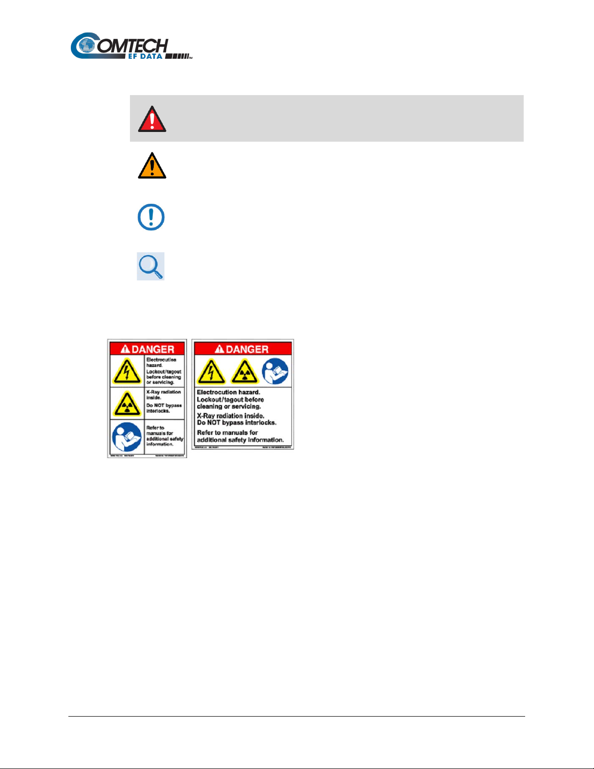
A WARNING indicates a potentially hazardous situation that, if not avoided,
could result in death or serious injury.
A CAUTION indicates a hazardous situation that, if not avoided, may result in
minor or moderate injury. CAUTION may also be used to indicate other
unsafe practices or risks of property damage.
A NOTE: gives you important information about a task or the equipment.
A REFERENCE directs you to important operational information or details
furnished elsewhere, either in the manual or in adjunct Comtech EF Data
publications.
Examples of Multi-Hazard Notices
Preface ii MN-SLM-5650C
Page 15
SLM-5650C / SLM-5650C-ODU Satellite Modem
Revision 1
Recommended Standard Designations
The Electronic Industries Association (EIA) designations supersede the Recommended Standard
(RS) designations. References to the old designations may be shown when depicting actual text
(e.g., RS-232) displayed on front panel menus, Web Server pages, serial remote interfaces,
Telnet Command Line Interfaces (CLIs), or unit rear panels. All other references in the manual
refer to EIA designations.
Carefully review the following information.
Safety and Compliance
Electrical Safety and Compliance
The unit complies with the EN 60950 Safety of Information Technology Equipment (Including
Electrical Business Machines) safety standard.
Electrical Installation
Connect the unit to a power system that has separate g round, line and neutral
conductors. Do not connect the unit without a direct connection to ground.
Class I Pluggable Equipment Type A-Protective Earthing
The cable distribution system/telecommunication network of this product relies on protective
earthing and the integrity of the protective earthing must be ensured
In Finland:
"Laite on liitettävä suojak osk ettim illa varustettuun pistorasiaan"
In Norway:
“Apparatet må tilkoples jordet stikkontakt”
In Sweden:
“Apparaten skall anslutas till jordat uttag”
Galvanic Isolator Use
Utrustning som är kopplad till skyddsjord via jordat vägguttag och/eller via annan utrustning och
samtidigt är kopplad till kabel-TV nät kan i visa fall medfőra risk főr brand. Főr att undvika detta
skall vid anslutning av utrustningen till kabel-TV nät galvanisk isolator finnas mellan utrustningen
och kabel-TV nätet.
Preface iii MN-SLM-5650C
Page 16

SLM-5650C / SLM-5650C-ODU Satellite Modem
Revision 1
Restricted Access Location
In Nordic Countries, equipotential bonding should be applied using the permanently connected
ground stud by a qualified service person.
Battery Warning
Risk of explosion if battery is replaced by an incorrect type. Dispose of used
batteries according to the instructions.
Operating Environment
DO NOT OPERATE THE UNIT IN ANY OF THESE EXTREME OPERATING
CONDITIONS:
• AMBIENT TEMPERATURES LESS THAN -10°C (14°F) OR MORE THAN
50°C (122°F) FOR THE INDOOR UNIT AND LESS THAN -32°C (-26°F)
OR MORE THAN 65°C (149°F) FOR THE OUTDOOR UNIT
• PRECIPITATION, CONDENSATION, OR HUMID ATMOSPHERES OF
MORE THAN 95% RELATIVE HUMIDITY FOR THE INDOOR UNIT
• UNPRESSURIZED ALTITUDES OF MORE THAN 3000 METRES (9842
FEET)
• EXCESSIVE DUST FOR INDOOR UNIT
• FLAMMABLE GASES
• CORROSIVE OR EXPLOSIVE ATMOSPHERES
Product Support
For all product support, please call:
+1.240.243.1880
+1.866.472.3963 (toll free USA)
By email:
esc@comtechefdata.com
Comtech EF Data Headquarters
http://www.comtechefdata.com
Comtech EF Data Corp.
2114 West 7th Street
Tempe, Arizona USA 85281
+1.480.333.2200
Preface iv MN-SLM-5650C
Page 17

SLM-5650C / SLM-5650C-ODU Satellite Modem
Revision 1
Warranty Policy
Comtech EF Data products are warranted against defects in material and workmanship for a
specific period from the date of shipment, and this period varies by product. In most cases, the
warranty period is two years. During the warr an t y period, Comtech EF Data will, at its option,
repair or replace products that prove to be defective. Repairs are warranted for the remainder of
the original warranty or a 90-day extended warranty, whichever is longer. Contact Comtech EF
Data for the warranty period specific to the product purchased.
For equipment under warranty, the owner is responsible for freight to Comtech EF Data and all
related customs, taxes, tariffs, insurance, etc. Comtech EF Data is responsible for the freight
charges only for return of the equipment from the factory to the owner. Comtech EF Data will
return the equipment by the same method (i.e., Air, Express, Surface) as the equipment was sent
to Comtech EF Data.
All equipment returned for warranty repair must have a valid R etur n Mat eria l Aut hor izat ion (RMA)
number issued prior to return and be marked clearly on the return packaging. Comtech EF Data
strongly recommends all equipment be returned in its original packaging.
Comtech EF Data Corporation’s obligations under this warranty are limited to repair or
replacement of failed parts, and the return shipment to the buyer of the repaired or replaced
parts.
Limitations of Warranty
The warranty does not apply to any part of a product that has been installed, altered, repaired, or
misused in any way that, in the opinion of Comtech EF Data Corporation, would affect the
reliability or detracts from the performance of any part of the product, or is damaged as the result
of use in a way or with equipment that had not been previously approved by Comtech EF Data
Corporation.
The warranty does not apply to any product or parts thereof where the serial number or the serial
number of any of its parts has been altered, defaced, or removed.
The warranty does not cover damage or loss incurred in transportation of the product. The
warranty does not cover replacement or repair necessitated by loss or damage from any cause
beyond the control of Comtech EF Data Corporation, such as lightning or other natural and
weather related events or wartime environments.
The warranty does not cover any labor involved in the removal and or reinstallation of warranted
equipment or parts on site, or any labor required to diagnose the necessity for repair or
replacement.
The warranty excludes any responsibility by Comtech EF Data Corporation for incidental or
consequential damages arising from the use of the equipment or products, or for any inability to
use them either separate from or in combination with any other equipment or products.
A fixed charge established for each product will be imposed for all equipment returned for
warranty repair where Comtech EF Data Corporation cannot identify the cause of the reported
failure.
Preface v MN-SLM-5650C
Page 18

SLM-5650C / SLM-5650C-ODU Satellite Modem
Revision 1
Exclusive Remedies
Comtech EF Data Corporation ’s warr anty, as stated is in lieu of all other warranties, expressed,
implied, or statutory, including those of merchantability and fitness for a particular purpose. The
buyer shall pass on to any purchaser, lessee, or other user of Comtech EF Data Corporation’s
products, the aforementioned warranty, and shall indemnify and hold harmless Comtech EF Data
Corporation from any claims or liability of such purchaser, lessee, or user based upon allegations
that the buyer, its agents, or employees have made additional warranties or representations as to
product preference or use.
The remedies provided herein are the buyer’s sole and exclusive remedies. Comtech EF Data
shall not be liable for any direct, indirect, special, incidental, or consequential damages, whether
based on contract, tort, or any other legal theory.
Preface vi MN-SLM-5650C
Page 19
SLM-5650C / SLM-5650C-ODU Satellite Modem
Revision 1
Chapter 1. INTRODUCTION
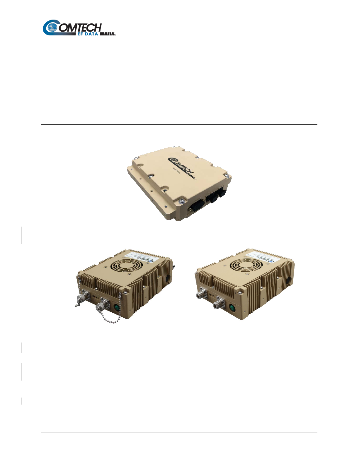
1.1 Overview
Figure 1-1. SLM-5650C Satellite Modem (Indoor Unit)
Outdoor Unit Outdoor Unit
with Caps without Caps
Figure 1-2. SLM-5650C-ODU Satellite Modem (Outdoor Unit)
TM
The SLM-5650C CyberLynx
• The SLM-5650C indoor unit (referred to as the SLM-5650C), shown in Figure 1-1, uses
conductive cooling and provides for mounting in any orientation via either the thermal
mounting rails or directly to the top or bottom surface.
Satellite Modem is offered in two unique packages:
• The SLM-5650C outdoor unit (referred to as the SLM-5650C-ODU), shown in Figure 1-2,
incorporates either conductive or convection cooling.
Introduction 1–1 MN-SLM-5650C
Page 20
SLM-5650C / SLM-5650C-ODU Satellite Modem
Description
SLM-5650C
SLM-5650C-ODU
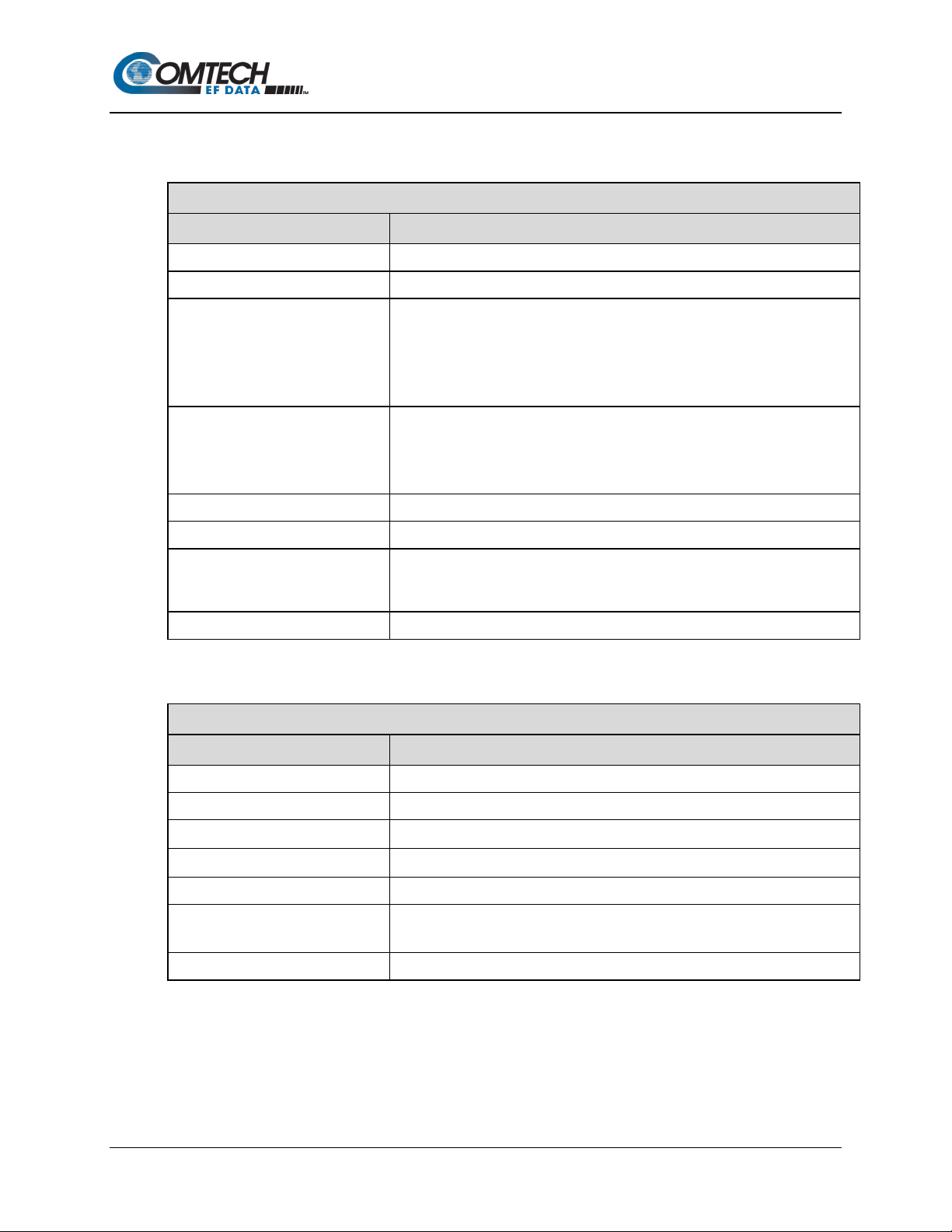
Volume
44.6 cubic inches
127 cubic inches
Maximum Power Consumption
27W
30W
11 VDC to 33 VDC,
Revision 1
Both modems satisfy the requirements for government and military communications system
applications that require state-of-the-art modulation and coding techniques to optimize satellite
transponder bandwidth usage, while retaining backward compatibility.
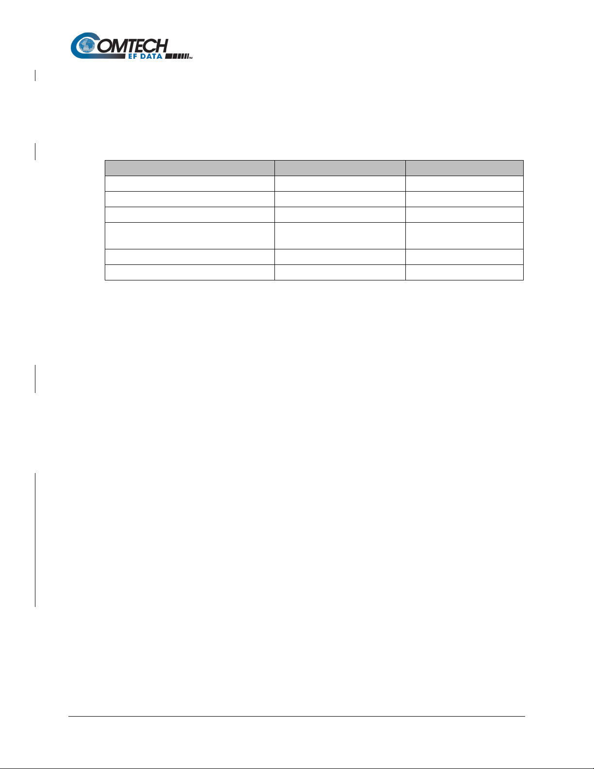
The table below provide some of the key physical characteristic of both units.
Table 1-1. SLM-5650C / SLM-5650C-ODU Physic al Ch ara cteri st ics
Dimensions 5.7” x 5.2” x 1.5” 7.7” x 5.9” x 2.8”
Prime Input Power 5 VDC, 5.4 Amps
2.2 Amps to 0.9 Amps
Cooling Conduction Convection/Conduction
Weight 2.7 lbs. (1.2 kg) 5.5 lbs. (2.5 kg)
The SLM-5650C:
• Meets requirements for SWaP (Size, Weight, and Power) constrained applications in a
high performance but low acoustic signature package.
• Supports Direct Sequence Spread Spectrum (DSSS) waveform and Comtech EF Data
(CEFD) proprietary Low Density Parity Check (LDPC) Forward Error Correction (FEC) in
three block sizes (Ultra Low Latency (ULL), Low Latency (LL), High Performance (HP))
and Turbo Product Code (TPC) FEC (3/4, 5/16, 21/44, 17/18, and 7/8 code rates).
• Is compliant with the provisions of Department of Defense (DoD) Standard MIL-STD-188-
165A, Interoperability of SHF Satellite Communications PSK Modems (Frequency
Division Mult ip le Ac c e s s [FDMA] Operation). NOT YET CERTIFIED.
• Can be controlled and monitored from a Personal Computer (PC) using serial remote,
Simple Network Management Protocol (SNMP), Hypertext Transfer Protocol (HTTP),
Hypertext Transfer Protocol Secured (HTTPS), and telnet.
The SLM-5650C-ODU has the same features listed above for the SLM-5650C, plus the following:
• Is IP67 rated.
• A selectable +13 or +18 VDC Low-noise Block Down Converter (LNB) voltage.
Introduction 1–2 MN-SLM-5650C
• An external TX mute capability, using the DB9 remote control connector.
• Normally Open (N/O) and Normally Closed (N/C) fault relay outputs, using the DB9
remote control connector.
• A different gender and pinout layout of the DB9 connector.
• A fault Light Emitting Diode (LED) that blinks continuously during the boot-up process.
Page 21
SLM-5650C / SLM-5650C-ODU Satellite Modem
2 Ch DAC
(
DAC3482
,
900mW)
TX RF Front
2 Ch ADC
(LTC2157-14,
650mW)
RX RF Front
RF Loopback
TX I
& Q Samples (LVDS
)
25
MHz
RJ
45
(Modem Control
)
RJ45
(GigaBit Interface)
Marvell
Ethernet
Switch
(88E6321)
20MHz
OCXO
250MHz VCO
PLL
L-Band
TX RF Output
(SMA)
L-Band
RX RF Input
(SMA)
TPC Codec
(3.3V I/O)
Turbo TX
Turbo RX
3.3 / 1.8V Level
Translator
3.3 / 1.8V Level
Translator
Remote
125/
250
MHz
Clock Distributor
IP TX
(
RGMII
)
UART TX
UART RX
SD Card
Adapter
DDR 3
M&
C Config
14 bit DAC
14 bit DAC
AGC
1
.8
V SPI
RX I & Q Samples (LVDS)
1.8V SPI
1.8V SPI
TX Level
Power
Supply
0.
9
V
1.
8V
2
.
5
V (
for DDR
4
)
3
.
3V
-3.3V
25MHz
1.
2V
(
for DDR4
)
MRAM
24MHz
32.768kHz
MODEM FPGA
Altera 10AX048H2F34
(1.2V & 1.8V I/O)
NXP Vybrid
M
&C Processor
IP Traffic
(RMII)
M&C Config
(MDIO)
14 bit DAC
20MHz Clock
Distribution
+
5V
Threaded
Locking
Connector
M&C Config
IP RX (RGMII)
Revision 1
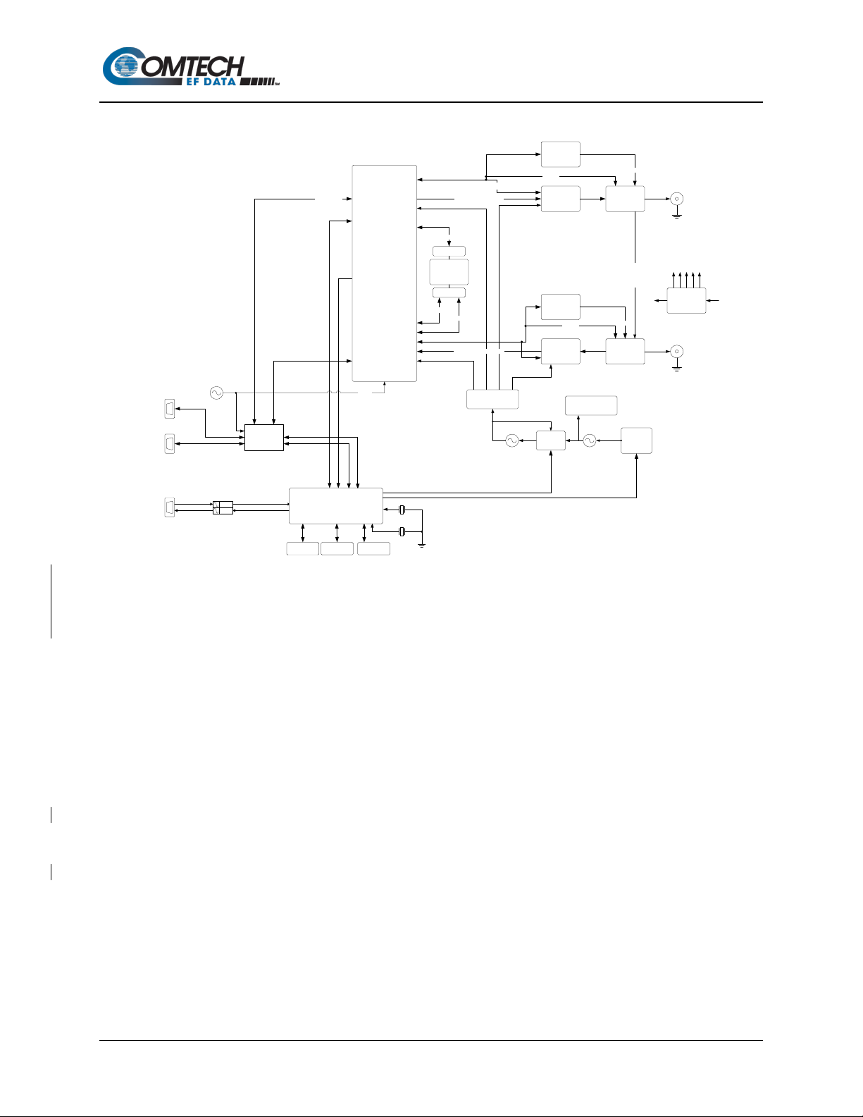
1.2 Functional Description
Figure 1-3. SLM-5650C / SLM-5650C-ODU Block Diagram
Figure 1-3 depicts the functional block diagram for the SLM-5650C and SLM-5650C-ODU. Both
modems have been designed to accommodate a wide range of currently required features, and to
support both near- and lo n g-term advances in software-defined radio technology as well as
advances in FEC technology.
The user has the ability to:
• Utilize an extensive array of built-in test capabilities
• Easily upgrade the modem’s operational capabilities in the field
• Easily update the modem’s firmware in the field
• Use a wide range of flexible remote control options
As shown in Figure 1-3, both modems accept Ethernet data to modulate an L-Band carrier. The
demodulator receives and demodulates the L-Band carrier. Recovered data is then output on the
Ethernet interface.
The Tx and Rx functions are independent with respect to modulation and coding. Both modems
can operate in simplex (Tx only or Rx only) or duplex mode.
Introduction 1–3 MN-SLM-5650C
Page 22

SLM-5650C / SLM-5650C-ODU Satellite Modem
Revision 1
1.3 SLM-5650C / SLM-5650C-ODU Features
Both modems incorporate the following features:
• SWaP optimized form factor
• Low weight and low power dissipa tio n
• L-Band (950 to 2000 MHz) Intermediate Frequency (IF) interface
• Ethernet Interface for remote control using Telnet, SNMP, HTTP, and HTTPS
• On board Gigabit Ethernet Bridge
• Full-featured, bui lt-in Bit Error Rate (BER) test-set
• Adaptive Equalizer for high order modulation types
• 8 kbps to 155.52 Mbps (Modulation-, code rate-, and interface-dependent)
• BPSK, QPSK, OQPSK, 8PSK, 8QAM, and 16QAM
• FEC Rates: 5/16, 1/3, 1/2, 2/3, 3/4, 5/6, 7/8, 21/44, 7/8, 17/18, .378, .451, .541
• Uncoded, Viterbi, Viterbi + Reed Solomon, and Sequential coding
• TPC codec
• LDPC coding in three block sizes: ULL, LL, and HP
• DSSS with LDPC
• TRANSEC Encryption
• Firmware updating capability
• 10 MHz Block Up Converter (BUC) and LNB references
• LNB voltage supplied through Radio Frequency (RF) connector
Introduction 1–4 MN-SLM-5650C
Page 23
SLM-5650C / SLM-5650C-ODU Satellite Modem
Revision 1
1.3.1 Physical Description
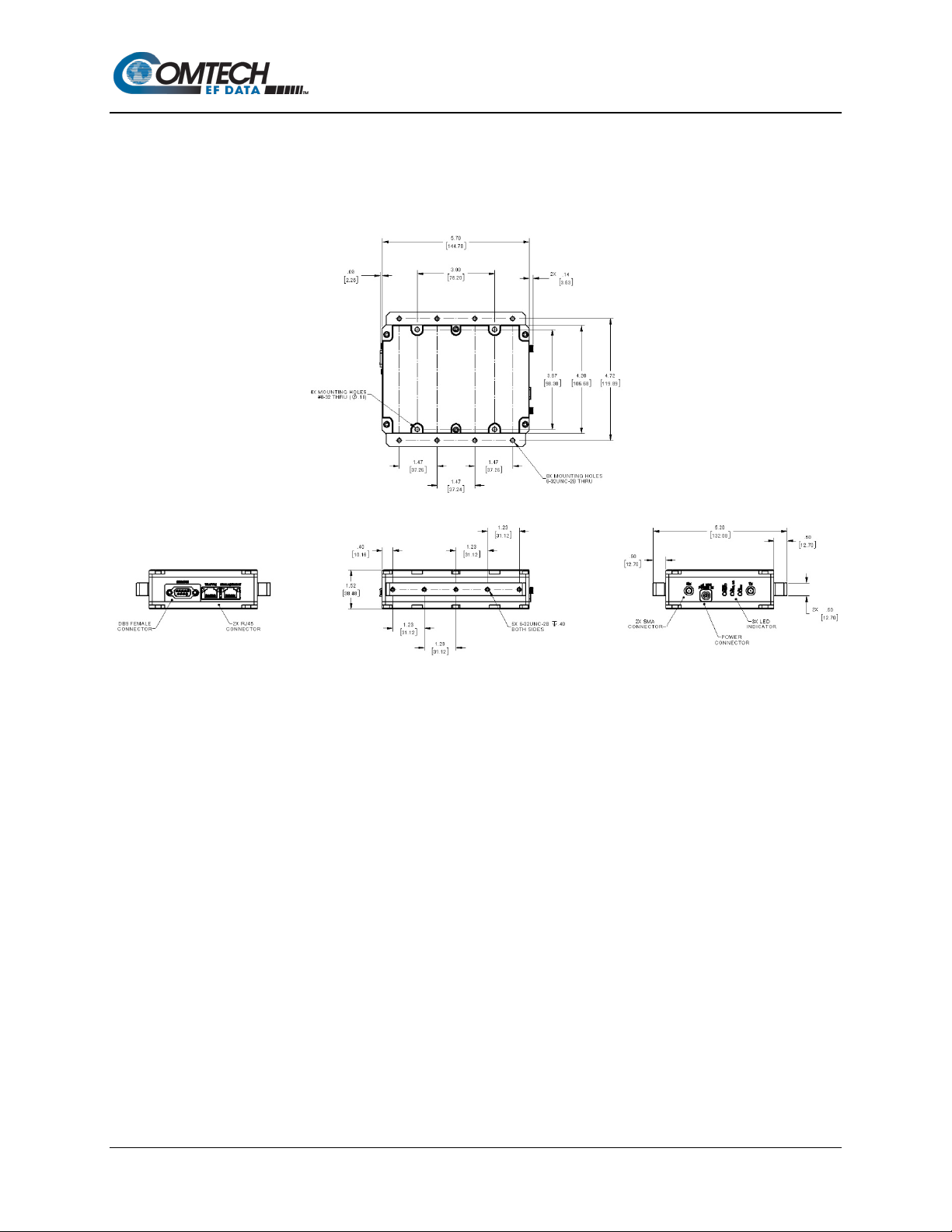
1.3.1.1 Dimensional Envelopes
Figure 1-4. SLM-5650C Indoor Unit Dimensional Envelop e
Introduction 1–5 MN-SLM-5650C
Page 24
SLM-5650C / SLM-5650C-ODU Satellite Modem
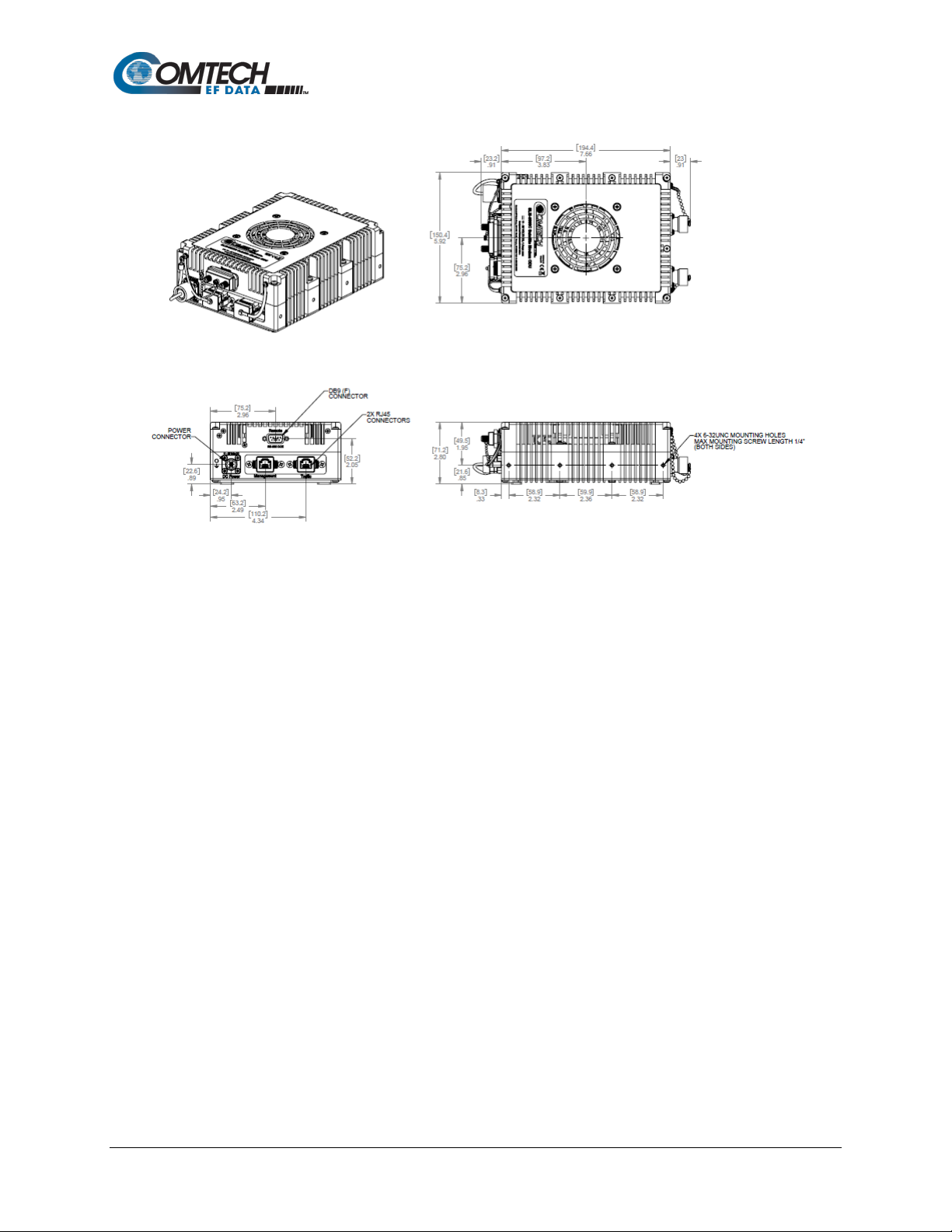
Revision 1
Figure 1-5. SLM-5650C-ODU Dimensional Envelope
Introduction 1–6 MN-SLM-5650C
Page 25

SLM-5650C / SLM-5650C-ODU Satellite Modem
Revision 1
1.3.2 Operational Features
1.3.2.1 Operating Modes
Both modems support Uncoded, Viterbi, Viterbi+Reed Solomon, Sequential, TPC, and LDPC
modes of operation. (STANAG 4486 (EBEM) in fall 2019)
1.3.2.2 Secure Management Interfaces
Chapter 6. MODEM CONFIGURATION
The modems support secure management interfaces, as part of its Management Security option.
Detailed information about these configurations and modes, and their function al a ss oc iation with
the Modem, is provided in the following chapters in this manual.
1.3.2.3 Data Interfaces
The modems support only an Ethernet data interface in GigE Bridge mode.
1.3.2.3.1 10/100/1000BASE-T (Gigabit Ethernet)
Chapter 8. 10/100/1000BASE-T
The 10/100/1000BASE-T (Gigabit Ethernet, or GbE) interface performs a simple bridge function
and passes IP packets, unaltered, in each direction between the Local Area Network (LAN)
(10/100/1000BASE-T interface) and Wide Area Network (WAN) (modulator / demodulator).
IP packet traffic is framed via High-level Data Link Control (HDLC) encapsulation by the modem
logic, and the modem is both the origination and termination point for HDLC encapsulation. HDLC
CRC-16 verification is performed on all received (from WAN) HDLC frames.
(GbE) INTERFACE
1.3.2.4 Independent Tx and Rx Function
The Tx (modulator) and Rx (demodulator) sides of the modem are functionally independent and
separately controllable. The baseband Tx and Rx sides of a communication channel passing
through the modem are independently configurable, including the ability to select different
parameters (to include data rate, coding, modulation, and spreading) in support of asymmetrical
operation.
Introduction 1–7 MN-SLM-5650C
Page 26

SLM-5650C / SLM-5650C-ODU Satellite Modem
Revision 1
1.3.2.5 Verification
Both modems include test modes and loopbacks for rapid verification of the correct functioning of
the modems. Of particular note is the IF loopback, which permits the user to perform a quick
diagnostic test without having to disturb external cabling. During the loopback, the receive
frequency configuration parameter is temporarily changed to match that of the Tx side, and an
internal RF switch connects the modulator output to the demodulator input. When normal
operation is again selected, all of the previous receive frequency is restored.
1.3.2.6 Updating Modem Firmware
Chapter 4. UPDATE FIRMWARE
Both modems store their firmware in flash memory, which allows the modems to upload firmware
downloads from an external PC once Ethernet connectivity has been established. Firmware
updates may be obtained free from CEFD via e-mail from CEFD Customer Support during normal
business hours.
1.3.3 Interoperability
1.3.3.1 Legacy Modems
The modems are compatible and interoperable with all specified SLM-5650C modes of operation
of the following legacy modems:
• SLM-5650A
• SLM-5650B
The remote control protocol is not backwards compatible.
Introduction 1–8 MN-SLM-5650C
Page 27
SLM-5650C / SLM-5650C-ODU Satellite Modem
Digital Data Rates
8 kbps with LDPC Spreading ON
Scrambling
V.35 and Synchronous
Output Power
+10 to -40 dBm, adjustable in 0.1 dB steps.
Output Impedance
Harmonics
From Carrier (CW) to the greater of the 12th harmonic or 4000 MHz –60 dBc
Revision 1
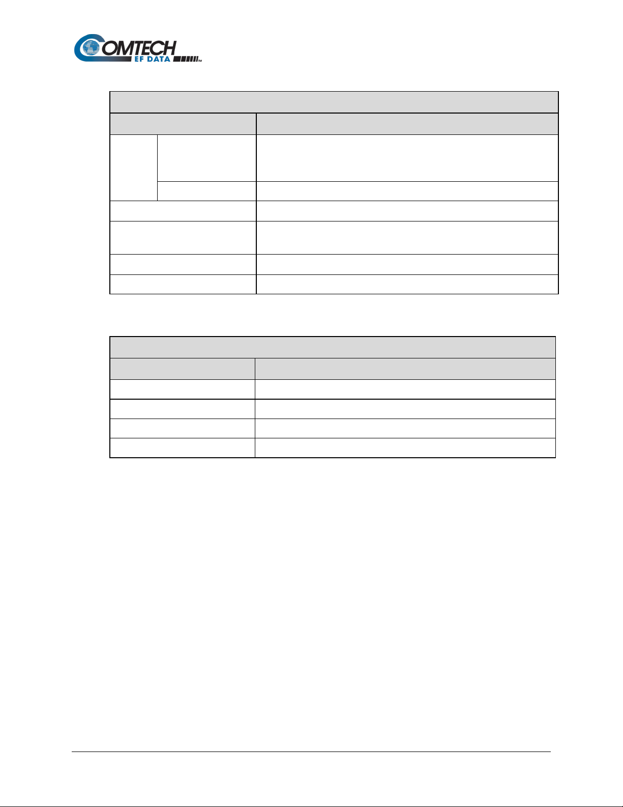
1.4 Summary of Specifications
Table 1-2. Summary of General Specifications
General Specifications
Parameter Specifications
Operating Frequency Range 950 to 2000 MHz ( in 1000 Hz steps)
Modulation Types BPSK, QPSK, OQPSK, 8PSK, 8QAM, and 16QAM
32 kbps with LDPC Spreading OFF
64 kbps for all other modes
* Maximum data rates are modulation and FEC dependent. Refer to
Appendix B.
Symbol Rate Range 14.795 ksps with Spreading ON
32 kbps for all other modes
* Maximum symbol rates are modulation and FEC dependent. Refer to
Appendix B.
INT REF Stability 6 x 10⁻⁸
Built-in Test (BIT)
Fault and status reporting, BER performance monitoring, IF Loop-back,
programmable test modes, built-in Fireberd emulation with all comprehensive
BER measurements.
Monitor and Control EIA-232, 10/100/1000BASE-T Et her net with HTTP, HTTPS, Telnet, and SNMP
Table 1-3. Summary of Modulator Specifications
Modulator Specifications
Parameter Specifications
Output Return Loss -9 dB (L-Band)
50 Ω
Spurious
From Carrier
± TX SR TO 500 MHZ –51 dBc (measured in a 10 kHz bandwidth).
Output Connections Indoor – SMA,
Outdoor – “N”-Type
Modulator Spectral Inversion Modem can invert the modulated spectrum.
Introduction 1–9 MN-SLM-5650C
Page 28
SLM-5650C / SLM-5650C-ODU Satellite Modem
Maximum Composite
+20 dBm or +40 dBc
Input Impedance
LDPC: ULL, LL, and HP
Closed Network
Revision 1
Table 1-4. Summary of Demodulator Specifications
Demodulator Specifications
Parameter Specifications
+10 to -55 dBm (SR>3.2 Msps)
Input
Power
Desired Carrier
+10 to 10·log
(SR≤3.2 Msps) where SR is in symbols per second
(SR/32000) -75 dBM
10
50 Ω
Input Connectors Indoor – SMA
Outdoor – “N”-Type
Carrier Acquisition Range
Input Return Loss -9 dB (L-Band)
Parameter Specifications
Uncoded, Viterbi, Viterbi+RS Per MIL-STD-188-165A
Sequential Closed Network
Turbo TPC
±
30 kHz, selectable
Table 1-5. Summary of Coding Options
Coding Options
Introduction 1–10 MN-SLM-5650C
Page 29

SLM-5650C / SLM-5650C-ODU Satellite Modem
1.5 Performance
1.5.1 Acquisition and Timing Performance Requirements
Revision 1
The following reference Energy per Bit to the Spectral Noise Density (Eb/No) is defined as the
-3
required Eb/No corresponding to a BER of 1 x 10
T
able 1-6. Acquisition and Timing Performance Requirements
with Reed-Solomon FEC not enabled.
Parameter Specification
Initial Acquisition
The modem achieves initial acquisition within the times as specified within ± 30 kHz at
the reference Eb/No
.
• For baseband data rates between 64 kbps and ≤ 128 kbps, the maximum initial
acquisition time is 500 seconds.
• For baseband data rates between 128kbps and ≤ 1544 kbps, the maximum initial
acquisition time is 30 seconds.
• For baseband data rates > 1544 kbps, the maximum initial acquisition time is 1.5
seconds.
Reacquisition
Reacquisition is achieved, as follows, after a period of up to 15 minutes of the absence
of signal when the carrier returns to within 500 Hz of its original frequency.
• For baseband data rates between 64 kbps and 128 kbps, the maximum
reacquisition time shall be 45 seconds.
• For baseband data rates between 128 kbps and 1544 kbps, the maximum
reacquisition time shall be 20 seconds.
• For baseband data rates greater than 1544 kbps, the maximum reacquisition time
shall be 1 second.
System Retention
Synchronization and BCI are maintained for all Eb/No above the reference Eb/No
(BPSK/QPSK/OQPSK/8PSK) for signal loss of up to 50 modulation symbol periods, with
a probability of at least 90 percent.
Receive Timing Jitter
The Rx output clock peak timing jitter cannot exceed ± 5 percent at the reference Eb/No
when the modulated signal meets the modulation timing jitter requirement.
Doppler
The modem meets the requirements with a Doppler shift, rate of change, and
acceleration for satellite inclination up to ± 7°, as presented in Table 1-7, and an
additional 0.5 dB added to the reference Eb/No.
Introduction 1–11 MN-SLM-5650C
Page 30

SLM-5650C / SLM-5650C-ODU Satellite Modem
Revision 1
Table 1-7. Doppler Requirements
Parameter C-Band X-Band Ku-Band Ka-Band
Doppler Shift in Hz ± 2475 ± 3535 ± 6045 ± 11,810
Doppler Rate of Change in Hz/sec ± 226 ± 270 ± 490 ± 1046
Doppler Acceleration in Hz/sec2 ± 243 ± 290 ± 526 ± 1124
1.5.2 Data Quality Performance
OM-73 Compatible Mode Performance
Operating in the OM-73-compatible mode, both modems vs. Eb/No performance with differential
encoding and data scrambling enabled do not exceed the values shown in Table 1-8 through
Table 1-14.
MIL-STD-188-165A Compatible Mode Performance
Operating with BPSK, QPSK, or OQPSK modulation in the MIL-STD-188-165A compatible mode,
both modems BER vs. Eb/No performance with differential encoding and data scrambling
enabled will not exceed values shown in Table 1-8 (without Reed-Solomon) or Table 1-9 (with
Reed-Solomon) tested in an IF back-to-back configuration over the BER range
-3
5 x 10
to 1 x 10⁻⁷.
Operating with 8PSK modulation and rate 2/3 pragmatic Trellis coding (without Reed-Solomon
outer coding), both modems vs. Eb/No performance is less than or equal to the values shown in
Table 1-10 when tested in an IF back-to-back configuration.
Operating with 8PSK modulation, rate 2/3 pragmatic Trellis coding, and Reed-Solomon (219,201)
outer coding, both modems vs. Eb/No performance is better than or equal to the values shown in
Table 1-11 when tested in an IF back-to-back configuration.
IESS-308 Compatible Mode Performance
When operating in the IESS-308 Compatible Mode, both modems BER vs. Eb/No performance is
as specified in IESS-308.
IESS-309 Compatible Mode Performance
When operating in the IESS-309 Compatible Mode, both modems BER vs. Eb/No performance is
as specified in IESS-309.
IESS-310 Compatible Mode Performance
When operating in the IESS-310 Compatible Mode, both modems BER vs. Eb/No performance is
as specified in IESS-310.
16QAM Coding Mode Performance
Both modems operating in the 16QAM mode provides back-to-back BER vs. Eb/No performance
better than or equal to the values shown in Table 1-12 when using the modulation form ats
indicated.
Introduction 1–12 MN-SLM-5650C
Page 31

SLM-5650C / SLM-5650C-ODU Satellite Modem
Revision 1
Turbo Coding Mode Performance
Both modems operating in the Turbo Code Mode provides back-to-back BER vs. Eb/No
performance better than or equal to the values shown in Table 1-13 when using the modulation
formats indicated.
Sequential Mode Performance
Both modems operating in the Sequential Mode provides back-to-back BER vs. Eb/ No performance
better than or equal to th e values show n in Table 1-14 when using the modula tion formats ind icat ed.
LDPC Coding Mode Performance
Both modems operating in an LDPC Mode provides back-to-back BER vs Eb/No performance
better than or equal to th e values show n in Table 1-11 through 1-13 when using t he indi c at ed bl o ck
size and modulation formats.
Introduction 1–13 MN-SLM-5650C
Page 32

SLM-5650C / SLM-5650C-ODU Satellite Modem
Eb/No (dB) Specifications
Viterbi Decoder
BER
1/2
3/4
7/8
Uncoded
10-3
3.8
5.0
6.3 10-4
4.7
5.9
7.1 10-5
5.3
6.6
7.8
10.8
10-6
5.9
7.2
8.4
11.6
10-7
6.5
7.8
9.0
12.4
10-8
7.1
8.3
9.5
13.0
Eb/No (dB) Specifications
Viterbi Decoder with Reed-Solomon
BER
1/2
3/4
7/8
10-6
4.1
5.6
6.7
10-7
4.4
6.0
7.1
10-8
5.0
6.3
7.5
Eb/No (dB) Specifications
Trellis Decoder
BER
2/3
5/6
10-3
6.5
8.7
10-4
7.3
9.4
10-5
8.1
10.1
10-6
8.9
10.8
10-7
9.6
11.6
10-8
10.2
12.3
Revision 1
1.6 BER Performance
BPSK/QPSK/Offset QPSK, Viterbi Decoding
Table 1-8. Viterbi Decoder BER
BPSK/QPSK/Offset QPSK, Viterbi Decoding and Reed-Solomon
Table 1-9. BSPK/QPSK/OQPSK Viterbi
with Reed-Solomon Decoder BER Performance
8PSK, Trellis Decoder
Table 1-10. 8PSK, Trellis Decoder BER Performance
Introduction 1–14 MN-SLM-5650C
Page 33

SLM-5650C / SLM-5650C-ODU Satellite Modem
Eb/No (dB) Specifications
Trellis Decoder with Reed-Solomon
BER
2/3
5/6
10-6
6.2
8.2
10-7
6.5
8.5
10-8
6.7
8.9
10-9
6.9
9.3
10
7.2
9.7
Eb/No (dB) Specifications
Viterbi Decoder with Reed-Solomon
BER
3/4
7/8
10-6
8.2
9.5
10-7
8.4
9.8
10-8
8.6
10.1
10-9
8.8
10.3
10
9.0
10.6
Eb/No (dB) Specifications
Turbo Product Code Decoder
BPSK
QPSK/OQPSK
8PSK
16QAM
21/44
5/16
21/44
3/4
7/8
17/18
3/4
7/8
17/18
3/4
7/8
10-6
3.3
2.5
3.3
3.9
4.3
6.8
6.5
7.1
10.0
7.6
8.2
10-7
3.4
2.8
3.4
4.1
4.4
7.1
6.9
7.2
10.6
8.0
8.4
10-8
3.5
3.1
3.5
4.3
4.5
7.4
7.2
7.3
11.2
8.4
8.5
Revision 1
8PSK, Trellis Decoder and Reed-Solomon
Table 1-11. 8PSK, Trellis Decoder
with Reed-Solomon BER Performance
-10
16QAM, Viterbi Decoder and Reed-Solomon
Table 1-12. 16QAM, Viterbi Decoder
with Reed-Solomon BER Performance
-10
Turbo Product Code (TPC) Decoding
Table 1-13. TPC Decoder BER Performance
BER
Introduction 1–15 MN-SLM-5650C
Page 34

SLM-5650C / SLM-5650C-ODU Satellite Modem
Eb/No (dB) Specifications
Sequential Decoder with / without Reed-Solomon
BPSK
QPSK/OQPSK
1/2
1/2
3/4
7/8
10-5
4.8
4.8
5.8
7.0
10-6
5.2
5.2
6.4
7.5
10-7
5.6
5.6
6.9
8.0
10-5
5.2
5.2
5.9
7.2
10-6
5.7
5.7
6.5
7.7
10-7
6.1
6.1
7.0
8.3
10-6
4.4
4.4
5.0
5.6
10-7
4.6
4.6
5.3
6.0
10-8
4.8
4.8
5.6
6.4
Eb/No (dB) Specification
BPSK
QPSK
1/2
1/2
2/3
3/4
10-5
10-6
10-7
3.5
3.5
4.0
4.5
10-8
3.7
3.7
4.2
4.7
Revision 1
Sequential Decoding with / without Reed-Solomon
Table 1-14. Sequential Decoding
with / without Reed-Solomon BER Performance
DESCRIPTION BER
Sequential – 64 kbps
Sequential – 1544 kbps
Sequential+RS (225,205)
LDPC ULL Decoding
Table 1-15. LDPC ULL Decoder BER Perform ance
BER
3.1 3.1 3.6 4.1
3.3 3.3 3.8 4.3
Introduction 1–16 MN-SLM-5650C
Page 35

SLM-5650C / SLM-5650C-ODU Satellite Modem
Eb/No (dB) Specification
BPSK
QPSK
8QAM
16QAM
.378
.451
.541
1/2
2/3
3/4
7/8
2/3
3/4
7/8
2/3
3/4
7/8
10-5
1.8
2.0
2.2
2.4
3.0
3.6
4.4
5.0
5.6
6.6
6.1
6.8
8.0
10-6
10-7
10-8
2.1
2.3
2.5
2.7
3.3
3.9
4.9
5.3
5.9
7.0
6.4
7.1
8.3
Eb/No (dB) Specification
BPSK
(O)QPSK
8QAM
16QAM
1/3
1/2
1/2
2/3
3/4
2/3
3/4
3/4
2.0
10-6
2.1
10-7
2.2
2.2
2.2
2.6
3.2
4.9
5.9
7.0
10-8
2.3
2.3
2.3
2.7
3.3
5.0
6.0
7.1
Revision 1
LDPC LL Decoding
Table 1-16. LDPC LL Decoder BER Performance
BER
1.9 2.1 2.3 2.5 3.1 3.7 4.5 5.1 5.7 6.7 6.2 6.9 8.1
2.0 2.2 2.4 2.6 3.2 3.8 4.7 5.2 5.8 6.8 6.3 7.0 8.2
LDPC HP Decoding
Table 1-17. LDPC HP Decoder BER Performance
BER
10-5
BER Performance with Adjacent Carriers
Both modems performance when operating with adjacent carriers complies with MIL-STD-188-165A
interface standard, Interoperability of SHF Satellite Communications PSK Modems (FDMA Operation)
2.0 2.0 2.4 3.0 4.7 5.7 6.8
2.1 2.1 2.5 3.1 4.8 5.8 6.9
Introduction 1–17 MN-SLM-5650C
Page 36

SLM-5650C / SLM-5650C-ODU Satellite Modem
Revision 1
BLANK PAGE
Introduction 1–18 MN-SLM-5650C
Page 37

SLM-5650C / SLM-5650C-ODU Satellite Modem
Revision 1
Chapter 2. INDOOR UNIT
INSTALLATION
2.1 Installation
This chapter applies to only the SLM-5650C.
PROPER HEAT SINKING IS REQUIRED.
For the indoor unit, make sure there is adequate heat sinking to the modem
enclosure.
Temperature at the modem enclosure should never exceed 50°C (122°F).
Installation of the SLM-5650C indoor unit depends heavily on its use scenario. The modem may
be installed in any orientation. There are mounting ears on both sides of the modem enclosure,
with four threaded hol es on the top/bottom and five on the side of each ear. There are also four
through-holes in the body of the enclosure. See Figure 1-4 for mounting hole locations.
The threaded mounting holes are #6-32. At least 0.25 inches of thread should be engaged for
mounting. The through-holes are sized for #8 hardware.
Critical items to consider when designing the installation are:
• Drawing heat away from the modem. This can be done by providing airflow across the
modem or by mounting the modem to a cooler metal surface, or both.
• The mounting method should be designed considering the expected shock and vibration
environment.
2.2 Connect External Cables
Chapter 3. EXTERNAL CONNECTORS
Connect the cables to the proper connectors on the modem housing.
AND PINOUTS
Installation 2–1 MN-SLM-5650C
Page 38

SLM-5650C / SLM-5650C-ODU Satellite Modem
2
Connect the power cable.
3
Revision 1
2.3 Connect Power Supply
Chapter 3. EXTERNAL CONNECTORS
Connect the direct current (DC) power cable to the pro per location on the modem by inserting the
jack and threading the sleeve into the housing. A non-threaded connector may also be used.
2.4 Configuration
If there is any problem with installation or initial operation, read Appendix A.
TROUBLESHOOTING for possible solutions.
Chapter 1. INTRODUCTION
All configurations are implemented locally via the unit’s loaded firmware.
Step Task
1 Read Chapter 1. INTRODUCTION before continuing.
AND PINOUTS
Turn power ON.
4 Do a check for the correct transmitter (Tx) and receiver (Rx) output signal levels and spectrums.
5 Use the modem web page to configure the unit.
Installation 2–2 MN-SLM-5650C
Page 39

SLM-5650C / SLM-5650C-ODU Satellite Modem
Step
Task
Connect the serial port of the modem to the serial port of a computer. The minimum pins needed
2
Open up a terminal session using an application like Putty or Tera Term.
Modify the following parameters:
Change the modems IP address. Enter the following commands:
Verify high security setting for SNMP V3 is turned OFF. Enter the following commands:
Revision 1
2.5 Determine the Modem IP Address
1
3
4
are 1, 2, & 3.
a. Emulation: VT100
b. Tx: CR+LF
c. Local Echo: yes
d. Baud rate: 115200 The modem is hard coded for this rate.
e. Data: 8 bit
f. Parity: None
g. Stop: 1
h. Flow Control: None
a. What is the IP Address?:
• Input: <0/IPA?
Displays: >0000/IPA=192.168.001.011.24
b. Change the IP address:
• Input the new IP address: <0/IPA=192.168.001.021.24
c. Confirm IP address:
• Input: <0/IPA?
Displays: >0000/IPA=192.168.001.021.24
a. What is the current setting for Modem Interface Security Mode?
• Input: <0/MIS?
5
b. If set to '1' (security mode ON), change the >0000/MIS= to '0' (security mode OFF).
Installation 2–3 MN-SLM-5650C
Displays: >0000/MIS=0 - or Displays: >0000/MIS=1
Page 40

SLM-5650C / SLM-5650C-ODU Satellite Modem
Revision 1
BLANK PAGE
Installation 2–4 MN-SLM-5650C
Page 41

SLM-5650C / SLM-5650C-ODU Satellite Modem
Revision 1
Chapter 3. EXTERNAL
CONNECTORS
3.1 Overview
3.1.1 SLM-5650C Connector Overview
The SLM-5650C connectors (Figure 3-1) provide all necessary external connections between the
modem and other equipment. Table 3-1 summarizes the connectors, grouped according to
service function. Note that the indoor unit does not support an On/Off switch.
Figure 3-1. SLM-5650C Connectors
AND PINOUTS
External Connectors and Pinouts 3–1 MN-SLM-5650C
Page 42

SLM-5650C / SLM-5650C-ODU Satellite Modem
Connector Group
Name
Connector Type
Function
IF
Type ’SMA’ female
(L-Band)
Type ’SMA’ female
(L-Band)
Terrestrial Data
MANAGEMENT
RJ-45 female
10/100Base-T, Remote Control
TRAFFIC
RJ-45 female
10/100/1000Base-T
Utility
Serial Remote Interface (RS232),
Voltage, and Constellation Monitor
Power/Ground
(Sect. 3.5)
+5 VDC POWER
Coaxial 5.5mm/2.5mm
Revision 1
Table 3-1. SLM-5650C Connectors
(Sect. 3.2)
Tx
Rx
(Sect. 3.3)
(Sect 3.4) REMOTE 9-pin Type ‘D’ female2
IN
The DB9 connector provided on the rear panel fea ture s threaded nuts to
ensure the mechanical integrity of the mated connections.
DC Power Jack
IF Output
IF Input
Analog Automatic Gain Control (AGC)
Modem Power
External Connectors and Pinouts 3–2 MN-SLM-5650C
Page 43

SLM-5650C / SLM-5650C-ODU Satellite Modem
Connector Group
Name
Connector Type
Function
IF
“N”-Type female
(L-Band)
“N”-Type female
(L-Band)
Terrestrial Data
MANAGEMENT
RJ-45 female
10/100Base-T, Remote Control
TRAFFIC
RJ-45 female
10/100/1000Base-T
Utility
Serial Remote Interface (RS232),
External Mute and Constellation Monitor
Power/Ground
(Sect. 3.5)
+11 VDC to +33
VDC POWER IN
Revision 1
3.1.2 SLM-5650C-ODU Connector Overview
The SLM-5650C-ODU connectors (Figure 3-2) provide all necessary external connections
between the modem and other equipment. Table 3-1 summarizes the connectors, grouped
according to service function. The outdoor unit is equiped with an On/Off switch with built-in
Status LED.
Figure 3-2. SLM-5650C-ODU Connectors
(Sect. 3.2)
Tx
Rx
(Sect. 3.3)
(Sect 3.4)
REMOTE 9-pin Type ‘D’ male
The DB9 connector provided on the rear panel fea ture s threaded nuts to
ensure the mechanical integrity of the mated connections.
Table 3-2. SLM-5650C-ODU Connectors
IF Output
IF Input
Analog AGC Voltage, Summary Alarm,
4-pin Mil-circular Modem Power
External Connectors and Pinouts 3–3 MN-SLM-5650C
Page 44

SLM-5650C / SLM-5650C-ODU Satellite Modem
L-Band IF Connector
Description
Direction
Revision 1
3.2 IF Connectors
3.2.1 SLM-5650C Tx, Rx L-Band IF Interface Connectors
The L-Band IF Interfaces use standard 50 Ω Type ‘SMA’ female connectors:
Table 3-3. Indoor Unit L-Band IF Interface Connectors
Tx 950-2000 MHz Transmit Output
Rx 950-2000 MHz Receive Input
Note: The RF spectrum must fit within the L-Band range.
3.2.2 SLM-5650-ODU Tx, Rx L-Band IF Interface Connectors
The L-Band IF Interfaces use standard 50 Ω “N”-Type female connectors:
Table 3-4. Outdoor Unit L-Band IF Interface Connectors
L-Band IF Connector Description Direction
Tx 950-2000 MHz Transmit Output
Rx 950-2000 MHz Receive Input
Note: The RF spectrum must fit within the L-Band range.
External Connectors and Pinouts 3–4 MN-SLM-5650C
Page 45

SLM-5650C / SLM-5650C-ODU Satellite Modem
Revision 1
3.3 Terrestrial Data Connectors
3.3.1 SLM-5650C Ethernet Traffic Connector (RJ-45)
The Traffic Ethernet connection is an 8-pin type ‘RJ-45’ 10/100/1000Base-T
connector and functions as an Ethernet bridge for data traffic. Auto Negotiate
only.
3.3.2 SLM-5650C Ethernet Management Connector (RJ-45)
The Management Ether net c onnec tion is an 8-pin type 'RJ-45' 10/100/1000BaseT connector. Remote control of the modem is provided using SNMP,
HTTP/HTTPS or Telnet with this port. Auto Negotiate only.
3.3.3 SLM-5650C-ODU Ethernet Connectors
The SLM-5650C-ODU incorporates sealed RJ45 Ethernet connectors.
Connectors: Samtec RPBE series
Mating Connectors: Samtec RCE series
or
Samtec RCEF Field Termination Kit
Go to https://www.samtec.com/cables/panel/sealed
(Acclimate
TM
IP68 sealed rectangular Ethernet cable assembly, plug)
to find these connectors.
External Connectors and Pinouts 3–5 MN-SLM-5650C
Page 46

SLM-5650C / SLM-5650C-ODU Satellite Modem
Pin #
Signal Function
Name
7
Not Connected
NC
3
Receive Data (RS232 input)
RD
8
Receive I Channel Constellation Monitor
RXI_MON
1
GROUND
GND
6
Not Connected
NC
2
Transmit Data (RS232 output)
TD
4
Receive Q Channel Constellation Monitor
RXQ_MON
9
Not Connected
NC
5
AGC Monitor (0 to 5V)
AGC_MON_OUT
Revision 1
3.4 Utility Connectors
Note that the pinout for the DB9 utility connector is NOT the same for the SLM-5650C and the
SLM-5650C-ODU units.
3.4.1 SLM-5650C Remote Connector (DB9)
This is a female Type ‘D’ 9-pin subminiature (DB9) connector that serves multipurpose roles. It provides RS-232 communications for a remote terminal, it
provides a means to monitor the real time I and Q samples from the demodulator
(constellation monitor), and it provides a receive signal strength indicator that can
be used to aid in peaking an antenna.
The DB9 connector is not a standard RS-232 serial port pinout.
Table 3-5. SLM-5650C Remote Connector (DB-9F) Pinout
External Connectors and Pinouts 3–6 MN-SLM-5650C
Page 47

SLM-5650C / SLM-5650C-ODU Satellite Modem
Pin #
Signal Function
Name
7
Receive I Channel Constellation Monitor
RXI_MON
3
Receive Data (RS232 input)
RD 8 Summary Fault (NO FAULT – Normally Closed)
SUMMARY FAULT - NC
1
AGC Monitor (0 to 5V)
AGC
6
External Mute
EXT MUTE*
2
Transmit Data (RS232 output)
TD
4
Receive Q Channel Constellation Monitor
RXQ_MON
9
Summary Fault (FAULT – Normally Open)
SUMMARY FAULT - NO
5
GROUND
AGC_MON_OUT
Revision 1
3.4.2 SLM-5650C-ODU Remote Connector (DB9)
This is a male Type ‘D’ 9-pin subminiature (DB9) connector that serves multipurpose roles. It provides RS-232 communications for a remote terminal, it
provides a means to monitor the real time I and Q samples from the demodulator
(constellation monitor), and it provides a receive signal strength indicator that can
be used to aid in peaking an antenna.
The DB9 connector is not a standard RS-232 serial port pinout.
Table 3-6. SLM-5650C-ODU Remote Connector (DB-9F) Pinout
* The Tx mute function is enabled by applying a total ‘low’ signal to Pin 6, or by grounding the pin.
If the Tx carrier is muted, the web status page ‘Virtual LED’ will turn Red. This page is normally Green when the
carrier is ‘ON’.
External Connectors and Pinouts 3–7 MN-SLM-5650C
Page 48

SLM-5650C / SLM-5650C-ODU Satellite Modem
Pin #
Signal Function
Range
A
DC Voltage Psostive
+11 VDC to +33 VDC
B
DC Voltage Psostive
+11 VDC to +33 VDC
C
Ground
D
Ground
DC Voltage
5V Nominal, 6V maximum
Input Current
6A maximum
Connector Type
Coaxial 5.5mm/2.5mm DC Power Jack (CUI Inc. PP3-002BH), enclosure threaded for retention
DC Voltage
Revision 1
3.5 Power/Ground Connector
3.5.1 SLM-5650C DC Power Connector
A standard coaxial connector supplies DC power to the modem. The enclosure is
threaded to accept a threaded connector sleeve for retention purposes. An nonthreaded installation may also be used. See Table 3-7 for specifications.
Table 3-7. SLM-5650C Power Connector
3.5.2 SLM-5650C-ODU DC Power Connector
A MIL-C-26482 series circular poer receptacle, Male, 4 Pin connector provide
the input for the +11 VDC to +33 VDC input voltage. See Table 3-8 for
specifications.
Table 3-8. SLM-5650C-ODU Power Connector
Input Current 2.7A maximum
Connector Type Outdoor Mil-C-26482 series circular poer receptacle, Male, 4 Pin
11 VDC to 33 VDC
Table 3-9. SLM-5650C-ODU Power Connector Pinout
External Connectors and Pinouts 3–8 MN-SLM-5650C
Page 49

SLM-5650C / SLM-5650C-ODU Satellite Modem
FW-xxxxxxx
Revision 1
Chapter 4. UPDATE FIRMWARE
4.1 Updating Firmware
This chapter applies to both the SLM-5650C and the SLM-5650C-ODU.
To ensure optimal performance, it is importan t to o perate the modem with its
latest available firmware.
The modem must be in the Low Security mode (SNMP Type = SNMPV1V2c) in
order to update firmware.
The modem stores its firmware internally in flash memory, which simplifies the firmware updating
process. The firmware update, once acquired, can be transferred from an external user PC once
Ethernet connectivity has been established with the modem.
This chapter outlines the complete firmware updating process as follows:
• Perform the update, without opening the modem, by connecting the unit to the Ethernet
port of the user PC.
• Obtain the firmware update via email from customer support and extract it to the user PC.
• Transfer the firmware update, via File Transfer Protocol (FTP), from the user PC to the
modem.
4.1.1 About Firmware Files, Naming, and Versions
The modem is factory-shipped with the latest version of operating firmware. If a firmware update
is needed, it can be acquired from CEFD Customer Support during normal business hours via email or on CD by standard mail delivery.
Figure 4-1. Firmware Naming Format
Update Firmware 4–1 MN-SLM-5650C
Page 50

SLM-5650C / SLM-5650C-ODU Satellite Modem
Revision 1
4.2 Obtain Modem IP Address
Chapter 7. REMOTE CONTROL
If the modem IP Address is known, continue to Section 4.3. Otherwise, do the following:
1. Connect the user PC to the modems serial remote port using the appropriate adapter.
2. Open a terminal emulator application, such as Putty or TeraTerm.
3. Establish a connection to the modem using the appropriate RS232 port configured for
115200 baud, 8 data bits, no parity, and 1 stop bit.
4. Issue the IPA remote command, see Chapter 7. REMOTE CONTROL for command syntax.
5. Open a DOS command window on the user PC and “ping” the modem using the IP Address
returned in step 4. Syntax is “ping xxx.xxx.xxx.xxx”.
6. Issue the MIS remote command, see Chapt er 7. REMOTE CONTROL for command syntax.
7. If Secure mode is ON, turn it OFF using the MIS command, and reboot the modem.
8. Establish an HTTP connection to the modem using the IP Address returned in step 4.
4.3 Bulk Firmware Update – Ethernet FTP Upload Procedure
Chapter 6. MODEM CONFIGURATION
Refer to Chapter 6. MODEM CONFIGURATION, Section 6.4.2.3 Admin | Upgrade for
instructions on how to upgrade the bulk firmware.
Update Firmware 4–2 MN-SLM-5650C
Page 51

SLM-5650C / SLM-5650C-ODU Satellite Modem
Revision 1
Chapter 5. ETHERNET-BASED
MANAGEMENT
5.1 Introduction
This chapter applies to both the SLM-5650C and the SLM-5650C-ODU.
The modem features an RJ-45 10/100/1000Base-T Ethernet management interface for the
purpose of remote monitor and control (M&C) of the modem. This port operates in the AutoNegotiation and Auto-Crossover mode.
5.2 Ethernet Management Interfaces & Protocols
A Windows-based user PC facilitates Ethernet-based remote M&C of the modem through the
following management protocols:
• Web Server (HTTP or H TTP S ) Interface. The non-secure (HTTP) or secure (HTTPS)
interface requires a compatible user-supplied web browser such as Internet Explorer,
FireFox, or Google Chrome.
• Simple Network Management Protocol (SNMP) with Public and Private Management
Information Base (MIB). The non-secure (SNMPv1/v2c) or secure (SNMPv3) interface
requires a user-supplied Network Management System (NMS) or a user-supplied
Management Information Base (MIB) File Browser.
• Telnet Interface. This non-secure modem interface requires use of the user PC’s command-
line interface, or a user-supplied terminal emulation program, such as Tera Term.
Ethernet-Based Management 5–1 MN-SLM-5650C
Page 52

SLM-5650C / SLM-5650C-ODU Satellite Modem
Revision 1
5.2.1 Secure Ethernet Management Interfaces
The varying degrees of Ethernet Management are dependent on the modem configuration.
• When Management Security is disabled (i.e., SNMPv1/v2c is selected).
o HTTP may be used.
o Telnet protocol may be used.
o FTP protocol may be used for firmware upgrade or Secure Socket Layer (SSL)
certificate upload.
o SNMP v1/v2c protocol may be used.
• When Management Security is enabled (i.e., SNMPv3 is selected).
o HTTPS protocol may be used.
o Telnet protocol is disabled.
o FTP protocol is disabled.
o SNMP v3 protocol may be used.
Ethernet-Based Management 5–2 MN-SLM-5650C
Page 53

SLM-5650C / SLM-5650C-ODU Satellite Modem
Revision 1
5.3 HTTP/HTTPS (Web Server) Interfaces
Chapter 6. MODEM CONFIGURATION
Chapter 4. UPDATE FIRMWARE
The modems embedded Web Server application provides the user with an easy to use interface
to configure and monitor all aspects of the modem. The modems HTTP/HTTPS Interface requires
Microsoft’s Internet Explorer 7.0 (or higher) and Mozilla Firefox 2.0 (or higher), via HTTP or
HTTPS (depending on the modem’s security level setting). See Chapter 6. MODEM
CONFIGURATION.
All Web Server Interfaces are accessible by typing (depending on the interface and/or
management mode) “http://xxx.xxx.xxx.xxx” or “https://xxx.xxx.xxx.xxx” into the browser’s
Address box (where “xxx.xxx.xxx.xxx” is the IP address of the modem or optional installed
interface). See Chap ter 4. UPDATE FIRMWARE, Sect. 4.2 for instructions on how to obtain the
IP address.
For all interfaces, the user is prompted to type in a valid User name
and Password, whether via an integrated Web page or a dialog box
similar to the one shown to the right. For all interfaces, the default for
both is comtech.
Ethernet-Based Management 5–3 MN-SLM-5650C
Page 54

SLM-5650C / SLM-5650C-ODU Satellite Modem
MIB File/Name
Fwxxxxx-xx.mib
CEFD MIB file gives the root tree for ALL CEFD products and consists of only
FW-xxxxxxxx_vYYY.MIB
FW-xxxxxxxx_vYYY.MIB
Revision 1
5.4 SNMP Interface
The SNMP is an Internet-standard protocol for managing devices on IP networks. An SNMP-
managed network consists of three key components:
• The managed device. This includes the modem.
• The SNMP Agent. The software that runs on the modem. The modems SN MP Ag en t
supports SNMPv1, SNMPv2c, and SNMPv3.
• The user-supplied Network Management System (NMS). The software that runs on
the manager.
5.4.1 Management Information Base (MIB) Files
MIB files are used for SNMP remote management of a unique device. A MIB file consists of a tree
of nodes called Object Identifiers (OIDs). Each OID provides remote management of a particular
function. These MIB files should be compiled in a user-supplied MIB Browser or SNMP Network
Monitoring System server.
The following MIB files are associated with the modem:
( ‘x’ indicates revision letter)
ComtechEFData MIB file
SLM-5650C OID MIB File
SLM-5650C Traps MIB file
Description
the following OID:
Name: comtechEFData
Type: MODULE-IDENTITY
OID: 1.3.6.1.4.1.xxxx
Full path:
iso(1).org(3).dod(6).internet(1).private(4).enterprises(1).comtechEFData(xxxx)
Module: ComtechEFData
MIB file consists of all of the OID’s for management of the modem functions.
Trap MIB file is provided for SNMPv1 traps common for base modems.
Ethernet-Based Management 5–4 MN-SLM-5650C
Page 55

SLM-5650C / SLM-5650C-ODU Satellite Modem
MIB2 SNMPv1 trap: Authentication Failure
5
MIB2 SNMPv2 notifications: Authentication Failure
1.3.6.1.6.3.1.1.5.5
Revision 1
5.4.2 SNMP Community Strings
In SNMP v1/v2c, the SNMP Community String is sent unencrypted in the SNMP
packets. Caution must be taken by the network administrator to ensure that
SNMP packets travel only over a secure and private network if security is a
concern.
The modem uses Community Strings as a password scheme that provides authentication before
gaining access to the modem agent’s MIBs. They are used to authenticate users and determine
access privileges to the SNMP agent.
Type the SNMP Community String into the us er -supplied MIB Browser or Network Node
Management software.
The user defines three Community Strings for SNMP access:
• Read Community default = public
• Write Community default = private
• Trap Community default = comtech
Note: Maximum number of characters for community strings shall not exceed 20. All printable
ASCII characters, except ’\’ and ‘~’ are allowed. No trailing spaces for community strings.
For proper SNMP operation, the modems MIB files must be used with the
associated version of the modems firmware.
5.4.3 SNMP Traps
These include unit faults, TX faults, and RX faults. A trap is sent both when a fault occurs and is
cleared.
The “Traps” file only needs to be compiled if SNMPv1 traps are to be used. Which style of traps
the modem sends can be configured by the user using the SLM5650CSNMPTrapVersion OID.
The modem supports the following MIB2 SNMPv1traps / SNMPv2 notif ications:
Ethernet-Based Management 5–5 MN-SLM-5650C
Page 56

SLM-5650C / SLM-5650C-ODU Satellite Modem
slm5650UnitAlarmV1
62471211
slm5650TxTrafficAlarmV1
62471212
slm5650UnitAlarmV2
slm5650TxTrafficAlarmV2
1.3.6.1.4.1.6247.121.2.1.2
slm5650RxTrafficAlarmV2
1.3.6.1.4.1.6247.121.2.1.3
Revision 1
The modem supports the following Alarms and Faults SNMPv1 traps / SNMPv2 notifications:
Table 5-1. Alarms and Faults SNMPv1 Traps
slm5650RxTrafficAlarmV1 62471213
Table 5-2. Alarms and Faults SNMPv2c/SNMPv3 Notification
1.3.6.1.4.1.6247.121.2.1.1
Ethernet-Based Management 5–6 MN-SLM-5650C
Page 57

SLM-5650C / SLM-5650C-ODU Satellite Modem
Revision 1
5.5 Telnet Interface
Chapter 7. REMOTE CONTROL
A Telnet interface is provided for the purpose of Equipment M&C via the standard Remote
Control protocol. The Telnet interface requires login at the Administrator and Read/Write User
Access Levels.
An example of the login process is shown below.
Figure 5-1. Telnet Login Screen
Ethernet-Based Management 5–7 MN-SLM-5650C
Page 58

SLM-5650C / SLM-5650C-ODU Satellite Modem
Revision 1
Once logged into the Telnet interface, the standard remote control i nte r fa ce (as defined in Chapter
7. REMOTE CONTROL) is accessible as shown in this next example:
Figure 5-2. Telnet Remote Control Interface
Ethernet-Based Management 5–8 MN-SLM-5650C
Page 59

SLM-5650C / SLM-5650C-ODU Satellite Modem
Revision 1
Chapter 6. MODEM
CONFIGURATION
6.1 HTTP/HTTPS Interface
This chapter applies to both the SLM-5650C and the SLM-5650C-ODU. It describes the
functionality of the modem’s HTTP/HTTPS Interface. The operational parameters are available
from these web pages.
6.2 Modem Web Page Access
Chapter 7. REMOTE CONTROL
A user-supplied web browser allows the full M&C of the modem from its Modem Web Interface.
The modems embedded web applications are designed for, and work best with, Microsoft’s
Internet Explorer Version 7.0 or higher.
See the Remote Commands Specifications tables found in Chapter 7. REMOTE CONTROL for
detailed descriptions of the configuration parameters featured on the individual web pages shown
in this chapter.
6.2.1 User Login
Chapter 2. INSTALLATION
All Web Server Interfaces are accessible by typing (depending on the interface and/or
management mode) “http://xxx.xxx.xxx.xxx” or “https://xxx.xxx.xxx.xxx” into the browser’s
Address box (where “xxx.xxx.xxx.xxx” is the IP address of the modem. See Chapter 2.
INSTALLATION, Sect. 2.5 for instructions on how to obtain the IP address.
Figure 6-1. Browser Address Box
Modem Configuration 6–1 MN-SLM-5650C
Page 60

SLM-5650C / SLM-5650C-ODU Satellite Modem
Revision 1
For all interfaces, the Windows Security screen appears and the user is prompted to type in a
valid User nam e and Password, whether via an integrated Web page or a dialog box like the one
shown to the right. For all interfaces, the default for both is comtech.
Figure 6-2. Windows Security Screen
Once the valid User name and Password is accepted, the browser window displays the
SLM-5650C as the Base Modem Web Interface Home page for both the SLM-5650C and the
SLM-5650C-ODU:
Figure 6-3. Web Interface Home Page
Modem Configuration 6–2 MN-SLM-5650C
Page 61

SLM-5650C / SLM-5650C-ODU Satellite Modem
Revision 1
6.2.2 Web Interface – Operational Features
Navigation
This manual uses a naming format for all web pages to indicate the depth of navigation needed to
view the referenced page: “Top Level Tab | 2
For example: “Admin | Access” is interpreted to mean first click the top-l evel ‘Admin’ navigation
tab; and then click the ‘Access’ Page tab.
Figure 6-4. Navigation Tab Examples
nd
Level Tab.”
Web Page Tabs
Chapter 7. REMOTE CONTROL
Each page is divided into one or more operational content tabs.
This manual explains the purpose and operation for each web page on a per-page basis. For
detailed information. See Chapter 7. REMOTE CONTROL.
Execution Buttons
Configuration changes generally do not take effect until a selection has been saved to nonvolatile memory. There may be one execution button per page or multiple execution buttons
within a page section. The label for each of these buttons is generally self-explanat or y, e.g.,
[Submit], [Clear], [Refresh], etc.
All execution buttons serve the same purpose – to save the configuration changes to non-volatile
memory, or to execute an update of the active page display.
Always make sure to click the execution button before selecting another web
page. Any changes made on that previous page will not be saved if the
execution button for those functions is not clicked.
Feature Selection
Drop-down menus provide access to multiple setting selections, where available, for a specific
function. Move the cursor to the drop-down tab, and then left-click the tab. The drop-down will
open and list the available selections. Move the cursor to the desired choice and then left-click
once again to select that choice.
Modem Configuration 6–3 MN-SLM-5650C
Page 62

SLM-5650C / SLM-5650C-ODU Satellite Modem
Revision 1
Text or Data Entry
Text boxes are provided any time an alphanumeric entry is required for access or configuration.
Move the cursor to the text box, and then left-click anywhere inside the box. Then, use the
keyboard to type in the desired alphanumeric string. Press Enter when done.
6.2.3 Web Interface Menu Tree
The following menu tree illustrates the options available via the Modem Web Interface:
Home Admin Configuration Status
Home Access Modem Status
Contact SNMP Utils Info
Upgrade LoadStore EventLog
Spreading ModemStatistics
AUPC PortStatistics
ODU ConfigLog
TRANSEC Firmware
This interface provides access to four navigation tabs (shown in blue):
• Home
• Admin
• Configuration
• Status
Beyond this top-level row of navigation tabs, the diagram illustrates the available 2
(shown in grey) that afford more specific user functionality.
Click any tab to continue.
nd
level tabs
Modem Configuration 6–4 MN-SLM-5650C
Page 63

SLM-5650C / SLM-5650C-ODU Satellite Modem
Revision 1
6.3 HTTPS Certificate
The modem Firmware has a default HTTPS Certificate installed. The default certificate is a selfsigned certificate built with the modem's default IP Address of 192.168.1.1 with a one-year
expiration date. Since most modern web browsers will flag certificate errors and may not even
allow secure connections when errors exist, most users will want to load their own certificate. An
X509 private key and certificate in Privacy-enhanced Electronic Mail (PEM) format may be loaded
as follows:
1. Make sure that the modem is in Non-Secure Mode (SNMPv1/v2c is selected).
2. Open a "My Computer" (Windows Explorer, not Internet Explorer) window on the PC.
3. Open a web browser and browse to the modem's Admin | Upgrade web page.
4. Copy the Uniform Resource Locator (URL) shown under paragraph 2. on that page into
the address bar of the "My Computer " (Windows Explorer, not Internet Explorer) window
and press Enter.
5. Windows Explorer will open an FTP connection the the modem and display a directory
list with a single entry that says "README.TXT".
6. Open another "My Computer" (Windows Explorer, not Internet Explorer) window and
navigate to the directory that includes the “.PEM” file. The first eight characters of the
“.PEM” file must contain the letters “5650C”.
7. Click on the file and drag it to the "My Computer" (Windows Explorer, not Internet
Explorer) window that displays the "README.TXT" and drop it in.
8. The modem will extract the key and certificate information and delete the “.PEM” file from
the directory.
9. Browser to the Status | Info web page and check the 20 byte SSL Certificate Fingerprint
(sometimes called the Thumbprint) shown there with the user certificate's fingerprint.
The user may now enable Secure Mode (SNMPv3 is selected), and reboot the modem.
Should a bad certificate get installed and HTTPS access is lost, do the following:
1. Connect a user PC to the modem’s serial remote interface.
2. Open a terminal program (such as PUTTY or TeraTerm) and establish a connection to
the SLM-5650C. RS232 settings are 115200 baud, 8 data bits, no parity, 1 stop bit.
3. Change the modem from Secure mode to Non-Secure mode using the MIS serial
command. See Chapter 7. REMOTE CONTROL for command syntax.
4. Reboot the modem.
5. Follow the procedure above to load another certificate.
Modem Configuration 6–5 MN-SLM-5650C
Page 64

SLM-5650C / SLM-5650C-ODU Satellite Modem
Revision 1
6.4 Modem Web Interface Page Descriptions
6.4.1 Home Page
Select the Home tab to continue.
Home | Home
From any location within the Modem Web Interface, click the Home top navigation tab to return
back to this top-level page. Use this page to identify the product and its current operating
firmware version.
Figure 6-5. Home | Home Page
Modem Configuration 6–6 MN-SLM-5650C
Page 65

SLM-5650C / SLM-5650C-ODU Satellite Modem
Revision 1
Home | Contact
The Contact page provides information on how to contact CEFD for sales or service support.
Figure 6-6. Home | Contact Page
Modem Configuration 6–7 MN-SLM-5650C
Page 66

SLM-5650C / SLM-5650C-ODU Satellite Modem
Revision 1
6.4.2 Admin Pages
The Administrator may use these pages to: Set up user names, passwords, and the host IP
Addresses, as required, to communicate with the Modem Web Interface.
The Admin pages are available only to users who have logged in using the
Administrator Name and Password.
Click the Access or Remote hyperlink to continue.
Admin | Access
Figure 6-7. Admi n | Access Page
Click [Submit Admin] once the desired configuration settings have been made on this page.
The Host IP is the Network Interface IP and mask of the c on figuration
computer.
Modem Configuration 6–8 MN-SLM-5650C
Page 67

SLM-5650C / SLM-5650C-ODU Satellite Modem
Revision 1
Admin | SNMP
Chapter 5. ETHERNET-BASED MANAGEMENT
Use this page to set and return administration information for the SNMP feature.
Click [Submit] to save any changes made on this page.
Click [Reboot Now] to reboot the modem to apply any SNMP Version change.
Figure 6-8. Admi n | SNMP Page
Modem Configuration 6–9 MN-SLM-5650C
Page 68

SLM-5650C / SLM-5650C-ODU Satellite Modem
Revision 1
Admin | Time
Use this page to set the SNTP Server Address, local time, and modem time and date.
Figure 6-9. Admin | Time Page
Click [Submit] to save any changes made on this page.
Modem Configuration 6–10 MN-SLM-5650C
Page 69

SLM-5650C / SLM-5650C-ODU Satellite Modem
Description
Parameters
FAST Upgrade
Demo Time Remaining
Revision 1
Admin | FAST
Use this page to upgrade FAST options and turn ON/OFF the Demo Mode.
Figure 6-10. Admin | FAST Page
When you obtain a FAST access code from CEFD, it will be for a specific option
register. Carefully enter each register-specific 20-character FAST access code in
sequence, and then click [Enter] when done. Up to three FAST Codes can be
entered simultaneously.
A message will display at the top of this section that states whether or not the codes
are accepted or if the upgrade is successful.
FAST Options Demo-Mode allows access to all modem options* for 30 calendar
days. This section displays the remaining time in days, hours, and minutes.
Use the drop-down list to set Demo-Mode as OFF or ON, and then click [Submit] to
execute the selection.
Modem Configuration 6–11 MN-SLM-5650C
Page 70

SLM-5650C / SLM-5650C-ODU Satellite Modem
“FW-xxxxxxx*.ZIP”
“FW-xxxxxxx*.ZIP”.
Revision 1
Admin | Upgrade
Use this page to REFLASH the modem and change the active firmware image.
Figure 6-11. Admin | Upgrade Page
There are two firmware slots in the modem. One is operational and the other is for the older
firmware.
To upgrade the firmware, follow the procedures shown in Figure 6-11.
Modem Configuration 6–12 MN-SLM-5650C
Page 71

SLM-5650C / SLM-5650C-ODU Satellite Modem
Revision 1
6.4.3 Configuration (Modem Configuration) Pages
The ‘Configuration’ pages are used to configure the Modulator, Dem odulator, and Ethernet
Bridge interface.
Select the Modem, Utils, LoadStore, Spreading, AUPC, ODU, or TRANSEC tabs to continue.
Configuration | Modem
Use this page to configure modem configuration parameters including Modem Frequency Band;
Transmit/Receive; and Tx Power Level.
The Configuration Pages may change slightly, depending on the modem
type selected. Not all modem parameters are valid, and could be hidden,
when certain modem types are selected.
Figure 6-12. Configuration | Modem Page
Click [Submit] as needed in each section to save any changes.
There are four sections to configure:
• Modem Type
• Tx
• Rx
• Tx-Power
Modem Configuration 6–13 MN-SLM-5650C
Page 72

SLM-5650C / SLM-5650C-ODU Satellite Modem
Modem Type
Transmit / Receive
Revision 1
Description Parameters
Modem Type is a major change for the modem and will set the configuration to
defaults for the selected modem type. The Tx power will be turned off.
The modem types are:
• OM-73
• MIL-165A
• IESS-308
• IESS-309
• IESS-310
• TURBO
• 16QAM
• AUPC
• LDPC
The modem will use less power when using either duplex set to Mod Only, Demod
Only, or Tx Sleep mode. The power can be reduced by 5 Watts.
The Interface Type should only be set for Gigabit Ethernet. Low Voltage Differential
Signaling (LVDS) is only used at the factory during development.
As an example, Reed Solomon is available when Mil-165A is selected as the Modem
Type.
The following options configure Tx and Rx, depending on the Modem Type.
Overhead:
Adding overhead will add a small percentage of data to the symbol rate of the
modem. Automatic Uplink Power Control (AUPC) is used to manage the modem Tx
power level when the System is impaired by adverse weather conditions.
FEC Type:
The FEC Type selection is dependant on the Modem Type. Selecting Turbo as a
Modem Type will change the FEC Type to Turbo.
Reed Solomon Encoder:
Reed Solomon Is available depending on the Modem Type of the modem.
• CW: Code Word, Depth:
The Reed Solomon Code Word and Depth is selectable using the dropdown box.
Differential Encoder / Decoder:
The Differential Encoder is available depending on the Modem Type of the modem.
Modulation Type:
The Modulation Type can be set to BPSK, QPSK, OQPSK, 8PSK, 8QAM, or 16QAM.
This is dependent on the Modem Type and the FEC Type.
Code Rate:
The Code Rate can be set to 1/1, 1/2, 1/3, 2/3, 3/4, 7/8, .378, .451, .541, 5/16, 21/44,
and 17/18. These selections vary, depending on the Modem Type, FEC Type, and
Modulation Type.
Data Rate:
The data rate range is detailed in Appendix B.
Modem Configuration 6–14 MN-SLM-5650C
Page 73

SLM-5650C / SLM-5650C-ODU Satellite Modem
Frequency:
Tx Power
Revision 1
Description Parameters
The L-Band frequency range is from 950 to 2000 MHz.
Spectrum:
Select Normal or Invert.
Spectral inversion is used for modem compatibility between modem manufactures.
Scrambler:
Scramblers can be set to Off, V.35, Modified-V.35, Synch (Reed Solomon), Intelsat
Business Service (IBS), Turbo, or OM73. These settings are dependent on Modem
Type.
Spreading Factor:
The Spread Factor distributes the user information over a larger frequency
bandwidth. The symbol rate is multiplied by the Spreading Factor number and is then
called the Chip Rate.
Polyn:
• Polynomial 1 is compatible with the SLM-5650B.
• It is not backwards compatible with the SLM-5650A.
• Polynomial 0 is backwards compatible with the SLM-5650A and
SLM-5650B.
GSN:
The GSN sets or returns the Tx Spreading Equation in the form abbbb, where:
a = 0 (for Polynomial 0) or 1 (for Polynomial 1):
• For Polyn 0, the GSN can be any number between 0-9999.
• For Polyn 1, the GSN can be any number between 0-4095.
Rx Sweep Width:
The Sweep Width is only set on the Rx. This value is normally set to 60 KHz. Reduce
the value when using DSSS spreading at low data rates. Adjust the Receive sweep
bandwidth to the minimum of either 60 kHz or 0.6 times the symbol rate when using
Spreading Factors greater than 1 at low data rates.
Adjust and turn on Tx power.
Rolloff:
The rolloff is fixed at 1.2 times the Chip Rate.
Modem Configuration 6–15 MN-SLM-5650C
Page 74

SLM-5650C / SLM-5650C-ODU Satellite Modem
Revision 1
Configuration | Utils
Use this page to configure modem operating parameters, including Real Time Clock; Test Modes;
Tx Miscellaneous, Rx Miscellaneous, Circ uit ID, Bu ilt -in BERT, 20 MHz Reference Adjust, and
AGC Monitor.
Click [Submit] as needed in each section to save any changes.
Figure 6-13. Configuration | Utils Page
Modem Configuration 6–16 MN-SLM-5650C
Page 75

SLM-5650C / SLM-5650C-ODU Satellite Modem
Real Time Clock
Test Modes
Tx Misc
Revision 1
Description Parameters
Set to get accurate stored event times.
CW Mode:
Tx-CW, Carrier Wave at the center frequency.
Tx Alt-1,0:
Use to confirm carrier null and offset suppression during test.
IF loopback:
Internal IF loop.
(Turn loopback off before changing the Modem Type)
An amber TEST indicator on the far right of the Web page will turn on and off to indicate that
a test test mode is on. The BERT functions are included in Test Modes. Turn all test modes
off during normal operation.
GBEI Flow Control:
GBEI Flow Control manages Ethernet Flow by sending out pause frames when the Ethernet
stream becomes congested. The directly attached Network device must have Flow Control
on to make this work properly.
The modem interface will send out pause frames to pause the Ethernet traffic periodically.
The pause frame is shown below:
Modem Configuration 6–17 MN-SLM-5650C
Page 76

SLM-5650C / SLM-5650C-ODU Satellite Modem
Revision 1
Description Parameters
Stats Sample Interval:
Modem Statistics will only report when the Stats Sample Interval is set to a periodic value.
GBEI WAN Buffer Length:
The GBEI WAN Buffer Length is the setting for the Tx Buffer for Ethernet data. It does not
directly add to the processing delay for the Tx Ethernet data. However, setting this too small
will cause packet drops.
View the Status \ Port Statistics \ Tx First In First Out (FIFO) Full to determine if the buffer
needs to be larger. The Tx FIFO will overflow and count packet drops if the GBEI WAN
buffer is too small.
Modem Configuration 6–18 MN-SLM-5650C
Page 77

SLM-5650C / SLM-5650C-ODU Satellite Modem
compatibility.
Rx Misc
Circuit ID
Built-in BERT
Revision 1
Description Parameters
BPSK Bit Order:
Match the BPSK Bit Order for the Tx and Rx. This is used for modem to modem
RxData Mask / Demod Faults Mask / Eb/No Alarms Mask:
Events for RxData, Demod Faults, and Eb/No Alarms can either be active or masked. The
events are not reported if masked.
RxData events can also be set to report all ones for no data.
Eb/No Alarm Point:
The Eb/No Alarm point can be set to a specific value to report an event if the Eb/No falls
below a desired value.
Modem Events are reported under the Status \ Event Log Tab. Click on the Code value to
read the event.
The modem operator can designate a Circuit ID for the modem. Use only numbers and
capital letters. Delete the dash characters before entering the Circuit ID.
The Tx or Rx can be turned on separately. The data pattern must match on the Tx and Rx
modems.
The Patterns are:
Modem Configuration 6–19 MN-SLM-5650C
Page 78

SLM-5650C / SLM-5650C-ODU Satellite Modem
operation.
20 MHz Reference
AGC Monitor
Revision 1
Description Parameters
Threshold:
The threshold setting was developed to match the setting on the Fireberd Test set. Match the
threshold setting to the Fireberd when testing with that test set. Setting the threshold to high
will allow the BERT to stay in syn c at lower Eb/No values.
The BERT results can be reset and the operator can insert 1 error to confirm BERT
Adjust
This adjustment affects the Carrier frequency, BUC reference, and the LNB reference.
The demodulator may not lock if the 20 MHz Reference is not adjusted properly when the
modem has DSSS spreading turned on.
Make sure the Frequency Counter reference is extremely accurate before adjusting.
Oscillator stability: 6 x 10
-8
The AGC voltage is relative to the receive signal level of the modem. The minimum is 0 and
the max is 5 VDC. These settings are for the AGC DC voltage on the serial connector pin 5
with signal ground on pin 1.
Modem Configuration 6–20 MN-SLM-5650C
Page 79

SLM-5650C / SLM-5650C-ODU Satellite Modem
Description
Parameters
Load/Store Modem
Revision 1
Configuration | LoadStore
Use this page to load or store modem configurations.
Figure 6-14. Configuration | Loa dStore Page
Click [Submit] to save any changes made on this page.
Configuration
There are 10 slots for saved configurations. They are used when there is a need to
recall many modem configurations.
Modem Configuration 6–21 MN-SLM-5650C
Page 80

SLM-5650C / SLM-5650C-ODU Satellite Modem
Description
Parameters
Spreading Calculator
View/Load/Store
Revision 1
Configuration | Spreading
Use this page to allow configuration of the DSSS applications.
Figure 6-15. Configuration | Spreading Page
Configuration
The calculator is used to determine the Chip Rate and Occupied bandwidth when
DSSS spreading is used. It can be used to calculate or configure the Tx or Rx of the
modem. Spreading is used in LDPC mode, BPSK.
This is used to confirm that there is a stored modem configuration in one of the ten
slots and to load and store a configuration. To view, Change the Configure Number
and select view to see if the slot is either empty or when it was stored.
Modem Configuration 6–22 MN-SLM-5650C
Page 81

SLM-5650C / SLM-5650C-ODU Satellite Modem
Description
Parameters
AUPC Params
Revision 1
Configuration | AUPC
Use this page to set the AUPC parameters.
Figure 6-16. Configuration | AUPC Page
This can be used by selecting overhead type as AUPC when the Modem type is set
at either AUPC or LDPC.
AUPC overhead adds 6.6665% to the symbol rate.
Modem Configuration 6–23 MN-SLM-5650C
Page 82

SLM-5650C / SLM-5650C-ODU Satellite Modem
Description
Parameters
ODU Control
LNB Status
Revision 1
Configuration | ODU
Use this page to view the ODU Control and to view the LNB Staus.
Figure 6-17. Configuration | ODU Page
* For the SLM-5650C, the LNB voltage is fixed at 18 VDC.
The LNB voltage is selectable at +13 VDC or +18 VDC. *
LNB DC Power:
Only turn on when connected to an LNB, otherwise leave it off to avoid damage to
other modems or test equipment.
LNB Current Threshold:
Set to a low and high value limits to report modem events when the LNB current is
out of range.
The LNB Status reports the LNB current and voltage of the LNB.
Modem Configuration 6–24 MN-SLM-5650C
Page 83

SLM-5650C / SLM-5650C-ODU Satellite Modem
Description
Parameters
Active Key
The frame length must match. The frame length can be changed when on or off-
The Current Transmission Encryption Key (TEK) increment is initiated by
Revision 1
Configuration | TRANSEC
Figure 6-18. Configuration | TRANSEC Page
Do the following steps to set the Active Key:
1. Enter Active seed key and passphrase.
• The Seed Key is 32 characters, upper and lower case, and some special characters.
• The Passphrase is 10 to 32 characters, upper and lower case only.
• Set the Frame Length. The frame length can be set to any integer number between 1 and 16.
line.
2. Click on Generate keys.
3. Confirm the key signatures match.
4. Select Operating Mode in Encryption Parameters.
a. Primary, or
b. Secondary
•
the operator at the Primary TRANSEC modem.
• The secondary TRANSEC TEK increment will follow automatically.
5. Turn encryption ON in Encryption Parameters.
6. Confirm Ethernet traffic.
Modem Configuration 6–25 MN-SLM-5650C
Page 84

SLM-5650C / SLM-5650C-ODU Satellite Modem
Description
Parameters
Future Key
Encryption
Revision 1
Activate Future Key:
• Activate the Future Key, or
• Load and activate a new key
The Future Key can be activated after using all the 26 TEK numbers. Then, another
set of TEK loads are available.
TRANSEC Encryption Overhead:
• Overhead will increase when encryption is on.
• TRANSEC Overhead Calculation:
(3+16 *N) / (16 * N) where N=Frame length
Next TEK:
• TEK loads can be updated periodically up to number 26.
• The operator at the Primary modem will load the Next TEK.
Do the following steps to set the Future Key:
1. Enter the Future Key seed key and passphrase.
2. Gener ate the F utur e Key.
The key signature must match on both modems.
Parameters
Frame Length:
• Large frame sizes use less overhead and are more efficient. However, a greater number of information
bits in the packet are impacted in noisy operating conditions.
• Small frame sizes use more overhead but fewer bits are impacted when losing a packet. Small frame
sizes are useful when the information bits are distributed over a wide spectral bandwidth using DSSS
spreading.
Reset All Keys: Zerioze.
• Make sure to reboot the modem after zeroizing the TRANSEC.
• Use the Admin \ Update tab.
• Impacts the Next TEK increment if a reboot is not done.
• The encryption state, On or Off, is maintained after zeroizing and rebooting the modem.
Modem Configuration 6–26 MN-SLM-5650C
Page 85

SLM-5650C / SLM-5650C-ODU Satellite Modem
Revision 1
6.4.4 Status Pages
The Status pages provide read-only status windows: General operating and configuration
information about the modem; Info about installed options; Event Log; Modem Statistics; Ethernet
Port Statistics; Network Processor Statistucs, Configuration Log; and Firmware Information.
Select the Status, Info, EventLog, ModemStatistics, PortStatistics, ConfigLog, or Firmware
tabs to continue.
Status | Status
Use this read-only page to view the modem’s current configuration and operation parameters:
• Alarms
• Rx Parameters
• Symbol Rates
• BERT
• Chip Rates
• General Status
• Internal Temperatures
Figure 6-19. Status | Status Page
Modem Configuration 6–27 MN-SLM-5650C
Page 86

SLM-5650C / SLM-5650C-ODU Satellite Modem
Revision 1
Status | Info
Use this read-only page to view general information about the modem and installed options.
Figure 6-20. Status | Info Page
Modem Configuration 6–28 MN-SLM-5650C
Page 87

SLM-5650C / SLM-5650C-ODU Satellite Modem
Description
Parameters
Event Log
Revision 1
Status | Event Log
Use this read-only page to view a scrollable display of recorded modem events.
Figure 6-21. Status | Event Log Page
Click [Refresh] to update the display with the most recently logged events.
Click [Clear Log] to clear the log. Once the log is cleared, the next time [Refresh] is clicked any
new events are logged and numbered beginning with ‘1’.
(Event #) Date / Time:
The first three columns display the event by the order in which it was logged, along
with the date and time the event was recorded.
Type:
The event is identified by its type in this column. Four event types are classified:
• Info
• Unit
• Tx Traffc
• Rx Traffic
Code:
Click on a hyperlinked fault code to display a page that describes the error code bit
positions.
Modem Configuration 6–29 MN-SLM-5650C
Page 88

SLM-5650C / SLM-5650C-ODU Satellite Modem
Description
Parameters
Statistics Log
Revision 1
Status | Modem Statistics
Use this read-only page view a scrollable display of recorded modem statistics.
Figure 6-22. Status | Modem Statistics Page
(Statistic #) Date / Time:
The first three columns display the statistic by the order in which it was logged, along
with the date and time the event was recorded.
Min Eb/No:
Avg Eb/No:
Click [Refresh] to update the display with the most recently logged statistics.
Click [Clear Log] to clear the log of all visible statistics. Once the log is cleared, the next time
[Refresh] is clicked any new statistics will be logged beginning with the number ‘1’.
Modem Statistics logs are collected when there is a periodic setting on the Config \ Utilities WEB
page, Stas Sample Interval.
Modem Configuration 6–30 MN-SLM-5650C
Page 89

SLM-5650C / SLM-5650C-ODU Satellite Modem
Description
Parameters
Port
RX Frame Errors and Rx discards are normal when the Internal BERT is
Revision 1
Status | Port Statistics
Use this read-only page to view Ethernet Port Statistics. Available Ports are LAN, WAN, and
Field Programmable Gate Array (FPGA).
Statistics
Figure 6-23. Status | Port Statistics Page
The Port Statistics page consists of a table of 64-bit counters. Table 6-1 defines the individual
counters.
turned on. The errors occur as the internal BERT is overwriting the
normal Ethernet Frame.
Modem Configuration 6–31 MN-SLM-5650C
Page 90

SLM-5650C / SLM-5650C-ODU Satellite Modem
Rx Packets
Total Number of received packets with Frame Check
Rx Frame Errors
Total number of received packets with Frame Errors.
TX Packets
Total Number of packets with Cyclic Redundancy
TX Short Frames
Total Number of packets with short frames.
Total Number of packets dropped because WAN
TX Discards
The number of packets sent that have a Multicast
The number of packets sent that have a Broadcast
The number of packets sent that have a Unicast
Octets (Out)
Total packets received with a CRC error not counted
Rx Errors (in)
Total packets received with Rx Error signal.
Pause (in)
The number of good Flow Control packets received.
The number of good packets received that have a
The number of good packets received that have a
Bad Octets (in)
Total bytes received in bad Ethernet packets.
Revision 1
Table 6-1. Summary of Counters for Port Statistics Pages
Port Attribute Description
Total Number of received packets.
FPGA
Rx FCS Errors
Sequence (FCS) Errors.
Rx Discards Total number of dropped packets.
Total Number of transmitted packets.
TX CRC
Check (CRC) errors.
TX Long Frames Total Number of packets with long frames.
TX FIFO Full
FIFO was full.
Total Number of dropped packets.
Multicast (Out)
Broadcast (out)
Unicast (Out)
destination Medium Access Control (MAC) address.
destination MAC address.
destination MAC address.
The number of bytes sent.
LAN
(Traffic port
connected to J12 RJ-
45)
(Ethernet)
WAN
(Traffic port
connected to satellite
interface)
FCS Errors (in)
Jabber (in)
in Fragments (In), Jabber (In) or Rx Errors (In).
Total packets received with length of more than
Maxsize (2048 bytes) but with invalid FCS.
The number of good packets that have multicast
destination MAC address.
Multicast (in)
Note: this address not included 802.3 Flow Control
messages counted in Pause (In) or does it included
Broadcast packets counted in Broadcast (in).
Broadcast (in)
Unicast (in)
broadcast destination MAC address.
Unicast destination MAC address.
Good Octets (in) Total good Ethernet bytes received.
Modem Configuration 6–32 MN-SLM-5650C
Page 91

SLM-5650C / SLM-5650C-ODU Satellite Modem
Description
Parameters
Configuration
Revision 1
Status | Config Log
Use this read-only page to view a scrollable display the configuration change log.
Figure 6-24. Status | Config Log Page
Log
Select a logging level from the drop-down menu, and then click [Refresh] to begin logging or to
update the page. The selections are:
• Logging Off
• Front Panel (n/a, No Front panel)
• Serial Remote
• Web
• SNMP
• Telnet
• NP Mailbox (n/a, No Network Processor plug in card)
• TransecMailbox (n/a, Transec is not a plug-in card)
When selecting the logging level, the modem will log changes from the current level and all prior
levels. For example, selecting “Web” will enable logging for the WEB pages, and Serial Remote.
The visible display provides the selected configuration change log information:
• Date / Time / Command
• Date / Time / Response
• Intf
Click [Clear Log] to clear the visible display.
Example:
Select Web
Modem Configuration 6–33 MN-SLM-5650C
Page 92

SLM-5650C / SLM-5650C-ODU Satellite Modem
Description
Parameters
Revision 1
Change the Loopback to OFF and then back ON. These are the commands initiated for that
change:
Modem Configuration 6–34 MN-SLM-5650C
Page 93

SLM-5650C / SLM-5650C-ODU Satellite Modem
Revision 1
Status | Firmware
Use this read-only page to view information about the boot firmware and bulk firmwares
programmed into the modem.
Modem Configuration 6–35 MN-SLM-5650C
Page 94

SLM-5650C / SLM-5650C-ODU Satellite Modem
Revision 1
Status | Constellation
Use this read-only page to view information about the boot firmware and bulk firmwares
programmed into the modem.
Figure 6-25. Status | Constellation Page
Modem Configuration 6–36 MN-SLM-5650C
Page 95

SLM-5650C / SLM-5650C-ODU Satellite Modem
Revision 1
Chapter 7. REMOTE CONTROL
7.1 Overview
This chapter applies to both the SLM-5650C and the SLM-5650C-ODU.
This chapter describes the protocol and message command set for remote monitor and control of the modem.
The electrical interface is an EIA-232 connection (for the control of a single device), and data is transmitted in asynchronous serial form
using ASCII characters. Control and status information is transmitted in packets of variable length in accordance with the structure and
protocol defined in later sections.
7.2 EIA-232
This is a much simpler configuration in which the Controller device is connected directly to the Target via a two-wire-plus-ground
connection. Controller-to-Target data is carried via EIA-232 electrical levels on one conductor, and Target -to-Controller data is carried in
the other direction on the other conductor.
7.3 Basic Protocol
All data is transmitted as asynchronous serial characters suitable for transmission and reception by a Universal Asynchronous Receiver
Transmitter (UART). In this case, the asynchronous character format supported is 8N1. The baud rate is fixed at 115,200 baud.
Serial Remote Control 7–1 MN-SLM-5650C
Page 96

SLM-5650C / SLM-5650C-ODU Satellite Modem
Revision 1
All data is transmitted in framed packets. The Controller is assumed to be a PC or ASCII dumb terminal, which is in charge of the process
of monitor and control. The Controller is the only device which is permitted to initiate, at will, the transmission of data. Targets are only
permitted to transmit when they have been specifically instructed to do so by the Controller.
All bytes within a packet are printable ASCII characters less than ASCII code 127. In this context, the Carriage Return and Line Feed
characters are consi dere d pr inta bl e.
All messages from Controller-to-Target require a response. This will be either to return data, which has been requested by the Controller,
or to acknowledge reception of an instruction to change the configuration of the Target.
Serial Remote Control 7–2 MN-SLM-5650C
Page 97

SLM-5650C / SLM-5650C-ODU Satellite Modem
Controller-to-Target
Start of Packet
Target Address
Address Delimiter
Instruction Code
Code Qualifier
Optional Arguments
End of Packet
<
(1 character)
(4 characters)
/
(1 character)
(3 characters)
= or ?
(1 character)
(n characters)
Carriage Return
(1 character)
Example: <0135/TFQ=70.2345{CR}
Target-to-Controller
Start of Packet
Target Address
Address Delimiter
Instruction Code
Code Qualifier
Optional Arguments
End of Packet
characters)
Example: >0654/RSW=32{CR}{LF}
Revision 1
7.4 Packet Structure
ASCII code 60
>
ASCII code 62
(1 character)
7.4.1 Start of Packet
• Controller-to-Target: This is the character ‘<’ (ASCII code 60).
• Target-to-Controller: This is the character ‘>’ (ASCII code 62).
The ‘<’ and ‘>’ characters indicate the start of packet. They may not appear anywhere else within the body of the message.
(4 characters)
ASCII code 47
/
ASCII code 47
(1 character)
(3 characters)
ASCII codes 61 or 63
=, ?, !, or *
ASCII codes
61, 63, 33, or 42
(1 character)
(From 0 to n
ASCII code 13
Carriage Return, Line
Feed
ASCII codes 13,10
(2 characters)
Serial Remote Control 7–3 MN-SLM-5650C
Page 98

SLM-5650C / SLM-5650C-ODU Satellite Modem
Revision 1
7.4.2 Target Address
This value is fixed to 0.
The Controller sends a packet with the address of a Target – the destination of the packet. When the Target responds,
the address used is the same address, to indicate to the Controller the source of the packet. The Controller does not
have its own address.
7.4.3 Address Delimiter
This is the “forward slash” character '/ ' (ASCII code 47).
7.4.4 Instruction Code
This is a three-character alphabetic sequence, which identifies the subject of the message. Wherever possible, the instruction codes have
been chosen to have some significance – e.g., TFQ for transmit frequency, RMD for receive modulation type, etc. This aids in the
readability of the message, should it be displayed in its raw ASCII form. Only upper case alphabetic characters may be used (A to Z,
ASCII codes 65 to 90).
Serial Remote Control 7–4 MN-SLM-5650C
Page 99

SLM-5650C / SLM-5650C-ODU Satellite Modem
Symbol
Definition
=
The ‘=’ code is used as the Assignment Operator (AO) and is used to indicate that the parameter defined by the preceding byte should
EXAMPLE: In a message from Controller-to-Target, TFQ=0950.0000 would mean “set the transmit frequency to 950 MHz.”
?
The ‘?’ code is used as the Query Operator (QO) and is used to indicate that the Target should return the current value of the
EXAMPLE: In a message from Controller-to-Target, TFQ? Would mean “return the current value of the transmit frequency.”
Symbol
Definition
=
The ‘=’ code is used in two ways:
acknowledge the message by replying with TFQ=(with no message arguments).
?
If the Controller sends an instruction to set a parameter to a particular value, then, if the value sent is not valid, the Target will
the message sent by the Controller.
!
If the Controller sends an instruction code which the Target does not recognize, the Target will acknowledge the message by echoing
EXAMPLE: XYZ!
*
If the Controller sends an instruction to set a parameter to a particular value, then, if the value sent is valid BUT the modulator will not
#
(ASCI code 35)
If the Controller sends a correctly formatted command BUT the modem is in local mode, it will not allow reconfiguration and will
respond with TFQ#
~
(ASCI code 126)
If a message was sent via a local modem to a distant end device or ODU, the message was transmitted transparently through the
local modem. In the event of the distant-end device not responding, the local modem would generate a response.
Revision 1
7.4.5 Instruction Code Qualifier
1. From Controller-to-Target, the only permitted values are:
(ASCII code 61)
(ASCII code 63)
be set to the value of the argument (s) which follow it.
parameters defined by the preceding byte.
2. From Target-to-Controller, the only permitted values are:
(ASCII code 61)
a. If the Controller has sent a query code to a Target.
(EXAMPLE: TFQ? (meaning ‘what’s the Transmit frequency?’), the Target would respond with TFQ=xxxx.xxxx, where xxxx.xxxx
represents the frequency in question.
b. If the Controller sends an instruction to set a parameter to a particular value, then, providing the value sent is valid, the Target will
(ASCII code 63)
(ASCII code 33)
acknowledge the message by replying (for example) with TFQ? (with no message arguments). This indicates that there was an error in
the invalid instruction, followed by the ! character.
(ASCII code 42)
permit that particular parameter to be changed at this time, the Target will acknowledge the message by replying, for example, with
TFQ* (with message arguments).
Serial Remote Control 7–5 MN-SLM-5650C
Page 100

SLM-5650C / SLM-5650C-ODU Satellite Modem
Symbol
Definition
EXAMPLE: 0001/RET~ (indicating that it had finished waiting for a response and was now ready for further comms).
^
(ASCI code 94)
If the Controller sends a correctly formatted command BUT the modem is in Ethernet Remote mode, it will not allow reconfiguration,
and will respond with TFQ^.
Revision 1
7.4.6 Optional Message Arguments
Arguments are not required for all messages. Arguments are ASCII codes for the characters 0 to 9 (ASCII codes 48 to 57), period (ASCII
code 46) and comma (ASCII code 44).
7.4.7 End Of Packet
• Controller-to-Target: This is the ‘Carriage Return’ character (ASCII code 13).
• Target-to-Controller: This is the two-character sequence ‘Carriage Return’, ‘Line Feed’ (ASCII codes 13 and 10). Both indicate the
valid termination of a packet.
Serial Remote Control 7–6 MN-SLM-5650C
 Loading...