

Page 1

Comtech EF Data is a n
AS9100 Rev B / ISO9001:2000 Registered Company
Vipersat
SLM-5650A
Satellite Network Modem Router
User Guide
MN-0000035 Revision 5
Page 2

Page 3
Vipersat SLM-5650A
Satellite Network Modem Router
User Guide
Part number MN-0000035
Document Revision 5
Firmware Version 1.9.1
April 8, 2011
Page 4

COMTECH EF DATA
VIPERSAT Network Products Group
3215 Skyway Court
Fremont, CA 94539
USA
Phone: (510) 252-1462
Fax: (510) 252-1695
www.comtechefdata.com
Part Number MN-0000035
Manual Revision 5
Firmware Version 1.9.1
©2011 by Comtech EF Data, Inc. All rights reserved. No part of this manual may be copied or
reproduced without prior written permission of Comtech EF Data, Inc.
IMPORTANT NOTE: The information contained in this document supersedes all previously
published information regarding this product. Product specifications are subject to change
without prior notice.
Comtech reserves the right to revise this publication at any time without obligation to provide
notification of such revision. Comtech periodically revises and improves its products and,
therefore, the information in this document is subject to change without prior notice. Comtech
makes no warranty of any kind with regard to this material, including but not limited to the implied
warranties of mechantability and fitness for a particular purpose. No responsibility for any errors
or omissions that may pertain to the material herein is assumed. Comtech makes no
commitment to update nor to keep current the information contained in this document.
All products, names, and services are trademarks or registered trademarks of their respective
companies.
Printed in the United States of America
Page 5

Document Revision History
Revision Date Description
0 1/16/08 Preliminary Release 2.0.x
1 6/30/08 Update content to reflect NP v1.3.2
2 8/29/08 Update content to reflect NP v1.4.1
3 10/24/08 Update content to reflect NP v1.5.1
4 4/20/09 Update content to reflect NP v1.6.1
5 4/08/11 Update content to reflect NP v1.9.1
New Features: Satellite Roaming (SOTM); IGMP Multicast Routing;
BPM Routing Mode; Multi-TDM Tunneling; STDMA Power Hunt.
Page 6

{ This Page is Intentionally Blank }
Page 7

Table of Contents
Chapter 1
General
How to Use This Manual . . . . . . . . . . . 1-1
Manual Organization . . . . . . . . . . . . 1-1
Chapter 1 — General . . . . . . . . . 1-1
Chapter 2 — Quick Start Configuration 1-1
Chapter 3 — Using the Web Server
Interface (WSI) . . . . . . . . . . . . 1-2
Appendix A — Network Addressing . . 1-2
Appendix B — Automatic Switching . . 1-2
Appendix C — Dynamic Power Control1-2
Appendix D — Glossary . . . . . . . . 1-2
Conventions and References . . . . . . . . 1-2
Product Description . . . . . . . . . . . . . . 1-4
Introduction . . . . . . . . . . . . . . . 1-4
Modem Features . . . . . . . . . . . . 1-4
Router Features . . . . . . . . . . . . . 1-5
Network and Bandwidth Management. . 1-5
Dynamic SCPC (dSCPC) . . . . . . . . 1-5
Turbo Product Coding . . . . . . . . . . 1-6
New in this Revision . . . . . . . . . . . . .1-6
v1.7.1 Release. . . . . . . . . . . . . . 1-6
Dynamic Routing via OSPF . . . . . . . 1-6
DPC Calibration for Maximum Power . . 1-6
LAN Enhancements . . . . . . . . . . .1-6
Flow Control . . . . . . . . . . . . . . 1-6
Proxy ARP . . . . . . . . . . . . . . 1-7
VLAN . . . . . . . . . . . . . . . . . 1-7
v1.8.1 Release. . . . . . . . . . . . . . 1-7
Acquisition Mode . . . . . . . . . . . 1-7
v1.9.1 Release. . . . . . . . . . . . . . 1-7
Satellite Roaming (SOTM) . . . . . . 1-7
IGMP Multicast Routing . . . . . . . . 1-7
Bridged Point-to-Multipoint (BPM) Routing
Mode . . . . . . . . . . . . . . . . 1-8
Multi-TDM Tunneling Mode . . . . . . 1-8
STDMA Power Hunt . . . . . . . . . . 1-8
Customer Support . . . . . . . . . . . . . . . 1-9
Contact Information . . . . . . . . . . . 1-9
Return Material Authorization . . . . . . 1-9
Reader Comments / Corrections . . . . 1-9
Chapter 2
Quick Start Configuration
Introduction . . . . . . . . . . . . . . . . . . . 2-1
Initial Configuration . . . . . . . . . . . . . . . 2-2
LAN Connection . . . . . . . . . . . . 2-2
Network Role . . . . . . . . . . . . . . . . 2-3
Setting Vipersat SLM-5650A Operating
Parameters. . . . . . . . . . . . . . . . . 2-4
Verify/Enter FAST Feature . . . . . . . 2-4
Set the Vipersat Working Mode . . . . 2-5
Set the IP Addressing . . . . . . . . . 2-7
Configure the Route Table . . . . . . . 2-8
Routing in a Vipersat Network. . . . . 2-8
Creating the Static Routes . . . . . . 2-9
Dynamic Routing with OSPF . . . . 2-10
Multicast Routing with IGMP . . . . 2-11
Set the Satellite Modem Configuration 2-11
Set the Vipersat Configuration . . . . 2-13
Set the Home State . . . . . . . . . . 2-15
Chapter 3
Using the Web Server Interface (WSI)
General . . . . . . . . . . . . . . . . . . . . . 3-1
Menu Descriptions . . . . . . . . . . . . . . . 3-3
Main Menu Bar . . . . . . . . . . . . . . . 3-3
Common Menu Commands . . . . . . . . . 3-3
Save Parameters to Permanent Storage 3-4
Log Off . . . . . . . . . . . . . . . . . 3-4
Information . . . . . . . . . . . . . . . . . 3-5
Administration . . . . . . . . . . . . . . . . 3-5
Vipersat Mode . . . . . . . . . . . . . 3-5
Routing Mode . . . . . . . . . . . . . 3-6
FAST Features . . . . . . . . . . . . . 3-7
Vipersat Configuration . . . . . . . . . . . . . 3-9
Vipersat . . . . . . . . . . . . . . . . . . . 3-9
Vipersat Role . . . . . . . . . . . . . 3-10
Node Name . . . . . . . . . . . . . . 3-10
Network ID . . . . . . . . . . . . . . 3-10
Receive Multicast Address . . . . . . 3-11
Managing IP Address . . . . . . . . . 3-11
Heart Beat . . . . . . . . . . . . . . 3-11
Management Security . . . . . . . . 3-12
SOTM . . . . . . . . . . . . . . . . . 3-12
ToC i
Page 8

STDMA Mode . . . . . . . . . . . . . . . 3-13
Allocation Method . . . . . . . . . . . 3-14
1 – Fixed . . . . . . . . . . . . . . 3-15
2 – Dynamic Slot . . . . . . . . . . 3-15
3 – Dynamic Cycle . . . . . . . . . 3-15
4 – GIR . . . . . . . . . . . . . . . 3-15
5 – Entry Channel . . . . . . . . . . 3-16
Acquisition Mode . . . . . . . . . . . 3-17
Group ID . . . . . . . . . . . . . . . 3-17
Cycles Per Burst Map . . . . . . . . . 3-18
Preamble Time . . . . . . . . . . . . 3-19
Guard Band . . . . . . . . . . . . . . 3-19
Slot Data Length . . . . . . . . . . . 3-19
Burstmap Multicast IP . . . . . . . . . 3-20
Power Hunt . . . . . . . . . . . . . . 3-21
Outbound IP . . . . . . . . . . . . . . 3-21
Automatic Remote Removal . . . . . 3-22
Remote List Table . . . . . . . . . . . 3-23
Add Remote to STDMA Group . . . 3-24
Set Remote Policies—GIR and ECM 3-25
GIR Remotes . . . . . . . . . . . . 3-25
ECM Remotes . . . . . . . . . . . . 3-25
Remove Remote from STDMA Group .
3-25
Enable/Disable Remote . . . . . . . 3-26
STDMA Statistics . . . . . . . . . . . . . 3-26
STDMA Hub Statistics . . . . . . . . . 3-27
STDMA Remote Statistics . . . . . . . 3-28
Vipersat Switching . . . . . . . . . . . . 3-28
Load Switching . . . . . . . . . . . . 3-30
STDMA Slot Capacity . . . . . . . . . 3-31
STDMA Switch Delay . . . . . . . . . 3-31
Percent Allocation . . . . . . . . . . . 3-32
SCPC Step Up Threshold . . . . . . . 3-32
SCPC Step Down Threshold . . . . . 3-32
SCPC Switch Delay . . . . . . . . . . 3-33
SCPC Step Up Excess . . . . . . . . 3-33
Dynamic Power Control Configuration . . 3-34
Dynamic Power Control . . . . . . . . 3-35
Target Eb/No . . . . . . . . . . . . . 3-35
Speed-Up Eb/No . . . . . . . . . . . 3-36
Target IP Address . . . . . . . . . . . 3-36
Maximum Power . . . . . . . . . . . 3-36
Margin . . . . . . . . . . . . . . . . . 3-37
Max Data Rate . . . . . . . . . . . . 3-37
Max Code Rate . . . . . . . . . . . . 3-37
Max Modulation . . . . . . . . . . . . 3-37
Home State . . . . . . . . . . . . . . . . 3-38
Set Current Configuration as Home State .
3-39
Force Modem to Home State . . . . . 3-39
Additional Routing Configuration . . . . . . . 3-40
Dynamic Routing . . . . . . . . . . . . . 3-40
OSPF Timeout Description . . . . . 3-43
Multicast Routing . . . . . . . . . . . . . 3-44
Appendix A
Network Addressing
Introduction . . . . . . . . . . . . . . . . . . A-1
The OSI Reference Model . . . . . . . . . . A-2
Layers 1 – 3 . . . . . . . . . . . . . . . . . A-2
Binary Math . . . . . . . . . . . . . . . . . . A-4
IP Addressing . . . . . . . . . . . . . . . . . A-6
IP Address Classes . . . . . . . . . . . . . A-6
Class A . . . . . . . . . . . . . . . . A-6
Class B . . . . . . . . . . . . . . . . A-6
Class C . . . . . . . . . . . . . . . . A-7
Class D . . . . . . . . . . . . . . . . A-7
Class E . . . . . . . . . . . . . . . . A-8
Private Network IP Addresses . . . . . A-8
Network Address Translation (NAT). . . A-8
Subnets . . . . . . . . . . . . . . . . . . . A-8
Subnet Mask . . . . . . . . . . . . . . . . A-9
Network Segments . . . . . . . . . . . . A-10
Default Gateways . . . . . . . . . . . . . A-11
MAC Addresses. . . . . . . . . . . . . . A-11
Appendix B
Automatic Switching
General . . . . . . . . . . . . . . . . . . . . B-1
Load Switching . . . . . . . . . . . . . . . . B-3
Overview . . . . . . . . . . . . . . . . . . B-3
Bandwidth Allocation and Load Switching by
the Hub STDMA Burst Controller . . . B-4
Load Switching—STDMA Hub . . . . . . . B-7
Hub Switching Parameters . . . . . . . B-7
Hub Switching Process . . . . . . . . . B-8
Load Switching—Remote . . . . . . . . . . B-9
Remote Switching Parameters . . . . . B-9
Determination for Switching . . . . . . B-10
Load Switch Example . . . . . . . . . . . B-10
Reduced Data Flow in Switched Mode
(SCPC) . . . . . . . . . . . . . . . B-12
ToS Switching. . . . . . . . . . . . . . . . . B-13
ii Vipersat SLM-5650A User Guide
Page 9

ToS Background . . . . . . . . . . . . . . B-13
Detection of ToS Stamped Packets . . B-14
Configuration . . . . . . . . . . . . . B-15
Example Implementations . . . . . . . . . B-16
ToS Switching Per Device . . . . . . . B-16
ToS Switching Per Traffic Type . . . . B-16
ToS Remarking . . . . . . . . . . . . B-17
ToS to DSCP Value Conversions . . . B-17
Mesh Setup Based on ToS Detection . B-18
Entry Channel Mode (ECM) Switching . . . . B-20
Fail-Safe Operation . . . . . . . . . . . . B-20
Appendix C
Dynamic Power Control
Introduction . . . . . . . . . . . . . . . . . . C-1
Description . . . . . . . . . . . . . . . . . . C-3
BER Waterfall Mapping . . . . . . . . .C-3
Delta Power Compensation . . . . . . .C-3
Theory of Operation . . . . . . . . . . . . .C-4
Configuration . . . . . . . . . . . . . . . . . C-7
Main DPC Menu . . . . . . . . . . . . . . .C-9
Enable DPC . . . . . . . . . . . . . C-10
Target Eb/No . . . . . . . . . . . . C-10
Speed Up Eb/No Range. . . . . . . C-11
Target DPC (IP) Address . . . . . . C-11
Calculate Max Power Menu . . . . . . . . C-11
Calibrated Data Rate . . . . . . . . C-13
DPC Margin . . . . . . . . . . . . . C-13
Nominal Power Level . . . . . . . . C-13
Max Data Rate . . . . . . . . . . . C-13
Max Code Rate . . . . . . . . . . . C-13
Max Modulation . . . . . . . . . . . C-13
Max FEC Type . . . . . . . . . . . C-13
Calculate Max Power . . . . . . . . C-13
Max Power . . . . . . . . . . . . . C-14
Signal Power Level Considerations . . . . . . C-15
Power Considerations. . . . . . . . . . . C-16
Cabling Considerations . . . . . . . . . . C-16
Appendix D
Glossary
. . . . . . . . . . . . . . . . . . . . . . . . . D-1
Index
. . . . . . . . . . . . . . . . . . . . . . . Index-1
ToC iii
Page 10

{ This Page is Intentionally Blank }
iv Vipersat SLM-5650A User Guide
Page 11

List of Figures
Chapter 1 Figures
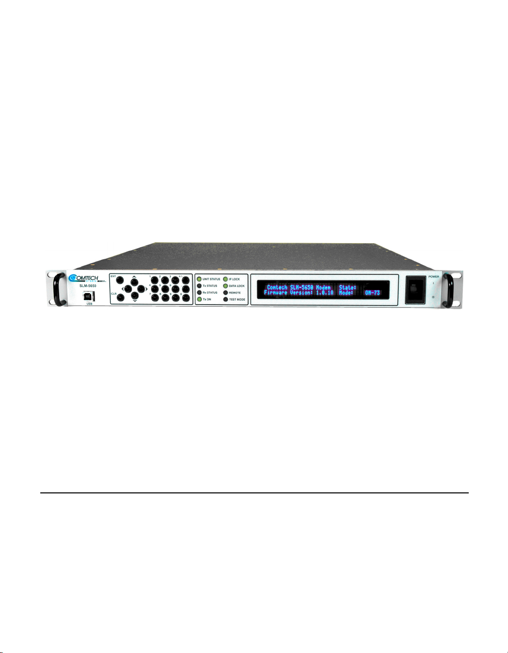
Figure 1-1 SLM-5650A Modem Router Unit . . . 1-4
Chapter 2 Figures
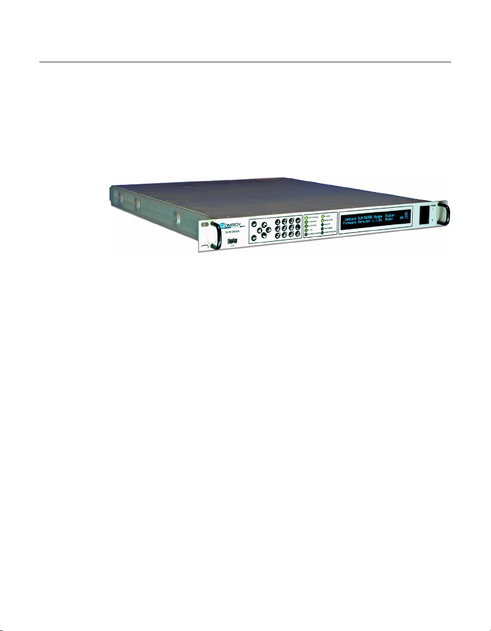
Figure 2-1 NP Splash Screen. . . . . . . . . . . . . . 2-3
Figure 2-2 FAST Features Page . . . . . . . . . . . 2-4
Figure 2-3 Front Panel, SLM-5650A Modem . . 2-5
Figure 2-4 Vipersat Working Mode Page . . . . . 2-6
Figure 2-5 LAN Interface Page. . . . . . . . . . . . . 2-7
Figure 2-6 Routes Table Page (Hub) . . . . . . . 2-10
Figure 2-7 Transmit Configuration Frame (Hub) .
2-11
Figure 2-8 Receive Configuration Frame (Hub) . .
2-12
Figure 2-9 Vipersat Configuration Page (Hub)2-13
Figure 2-10 Home State Configuration Page . 2-15
Chapter 3 Figures
Figure 3-1 Network Processor Splashscreen . . 3-2
Figure 3-2 Main Menu Bar . . . . . . . . . . . . . . . . 3-3
Figure 3-3 Save Configuration Command . . . . 3-4
Figure 3-4 NP Logoff Command. . . . . . . . . . . . 3-4
Figure 3-5 Home Page . . . . . . . . . . . . . . . . . . . 3-5
Figure 3-6 Working Mode Page . . . . . . . . . . . . 3-6
Figure 3-7 FAST Features Page . . . . . . . . . . . 3-8
Figure 3-8 Front Panel, SLM-5650A Modem . . 3-8
Figure 3-9 Vipersat Configuration Page (Hub) . 3-9
Figure 3-10 . Figure 3-10 Vipersat Configuration
Page (Remote) . . . . . . . . . . . . . . . . . . 3-10
Figure 3-11 Disable SOTM for Remote . . . . . 3-12
Figure 3-12 STDMA Page (Hub, Dynamic Cycle
mode). . . . . . . . . . . . . . . . . . . . . . . . . . 3-13
Figure 3-13 STDMA Page (Remote) . . . . . . . 3-14
Figure 3-14 Hub Type Allocation Menu . . . . . 3-15
Figure 3-15 Hub STDMA Acquisition Mode . . 3-17
Figure 3-16 Group ID field . . . . . . . . . . . . . . . 3-18
Figure 3-17 Cycles Per Burst Map field . . . . . 3-18
Figure 3-18 Slot Preamble Time display . . . . 3-19
Figure 3-19 Slot Guardband field . . . . . . . . . . 3-19
Figure 3-20 Slot Data Length (Dynamic Cycle)3-20
Figure 3-21 Burstmap Multicast IP field . . . . . 3-20
Figure 3-22 Power Hunt field . . . . . . . . . . . . .3-21
Figure 3-23 Outbound IP field. . . . . . . . . . . . .3-22
Figure 3-24 Automatic Remote Removal . . . . 3-22
Figure 3-25 STDMA Remote List Table. . . . . 3-23
Figure 3-26 Remote List Table, GIR Hub . . . .3-24
Figure 3-27 Remote List Table, ECM Hub . . . 3-24
Figure 3-28 Delete Table Entry field . . . . . . . . 3-26
Figure 3-29 Remote Status selection . . . . . . . 3-26
Figure 3-30 STDMA Hub Statistics Page . . . .3-27
Figure 3-31 STDMA Remote Statistics Page .3-28
Figure 3-32 Switching Page (Hub) . . . . . . . . . 3-29
Figure 3-33 Switching Page (Remote) . . . . . . 3-30
Figure 3-34 STDMA Slot Capacity field . . . . .3-31
Figure 3-35 STDMA Switch Delay field . . . . .3-31
Figure 3-36 Percent Allocation field . . . . . . . .3-32
Figure 3-37 SCPC Step Up Threshold field . . 3-32
Figure 3-38 SCPC Step Down Threshold field3-33
Figure 3-39 SCPC Switch Delay field . . . . . . . 3-33
Figure 3-40 SCPC Step Up Excess field . . . .3-33
Figure 3-41 DPC Configuration (Hub & Remote) .
3-34
Figure 3-42 DPC Configuration (Hub Expansion
Demod) . . . . . . . . . . . . . . . . . . . . . . . .3-35
Figure 3-43 Home State Configuration Page .3-38
Figure 3-44 OSPF Parameters Page . . . . . . .3-41
Figure 3-45 IGMP Parameters Page . . . . . . .3-44
Appendix A Figures
Figure A-1 The Seven OSI Protocol Layers . . A-2
Figure A-2 Bits and Bytes . . . . . . . . . . . . . . . . A-4
Figure A-3 Binary to Decimal Conversion. . . . A-4
Figure A-4 IP Address Classes A, B, C . . . . . A-7
Figure A-5 NAT Router Example . . . . . . . . . . A-8
Figure A-6 Default Subnet Masks for IP Classes .
A-9
Figure A-7 ANDing an IP address and a subnet
mask. . . . . . . . . . . . . . . . . . . . . . . . . . A-10
Figure A-8 Network Segments . . . . . . . . . . . A-10
Figure A-9 Router as Default Gateway. . . . . A-11
Figure A-10 Network Node MAC Addresses A-12
LoF v
Page 12

Appendix B Figures
Appendix C Figures
Figure B-1 Hub Load Switching Page . . . . . . .B-7
Figure B-2 Remote Load Switching Page . . . .B-9
Figure B-3 Load Switching diagram . . . . . . . .B-11
Figure B-4 ToS Field Location within the IP Header
B-13
Figure B-5 Remote ToS Switching menu . . . .B-15
Figure B-6 Per Device ToS Switching Example . .
B-16
Figure B-7 Per Type ToS Switching Example B-16
Figure B-8 ToS Remarking Application . . . . .B-17
Figure B-9 ToS and DSCP Conversion Chart B-18
Figure B-10 ECM Switch Recovery: < 3 minutes .
B-21
Figure B-11 ECM Switch Recovery: > 3 minutes .
B-22
Figure C-1 Data Rate to Power Relationship, DPC
C-5
Figure C-2 Excessive Max Power Example . . C-6
Figure C-3 DPC Configuration screen, CLI . . C-9
Figure C-4 DPC dialog, Parameter Editor . . C-10
Figure C-5 DPC Calculate Max Power screen, CLI
C-12
Figure C-6 DPC Calibration dialog, Parameter
Editor . . . . . . . . . . . . . . . . . . . . . . . . . C-12
Figure C-7 Signal Power Levels, Remote SiteC-15
vi Vipersat SLM-5650A User Guide
Page 13

Chapter 2 Tables
Table 2-1 SLM-5650A Network Roles and
Functions . . . . . . . . . . . . . . . . . . . . . . . . 2-3
Table 2-2 Vipersat Feature Configuration . . . . 2-6
Appendix B Tables
Table B-1 STDMA ACK Message . . . . . . . . . .B-5
Table B-2 ToS Switching Settings . . . . . . . . .B-15
Appendix C Tables
Table C-1 DPC Parameters, Main Menu . . . . .C-7
Table C-2 DPC Parameters, Calculate Max Power
Menu . . . . . . . . . . . . . . . . . . . . . . . . . . .C-8
Table C-3 Typical Coaxial Cable Characteristics .
C-17
List of Tables
LoT vii
Page 14

{ This Page is Intentionally Blank }
viii Vipersat SLM-5650A User Guide
Page 15

GENERAL
How to Use This Manual
This manual documents the enhanced Vipersat features and functions of the
SLM-5650A Satellite Network Modem Router, and guides the user in how to
configure this product for use in a Vipersat network. The material covered
addresses only those areas specific to an SLM-5650A running in Vipersat mode,
and complements the universal features and functions described in the
SLM-5650A Installation and Operation Manual.
C
HAPTER
Earth station engineers, technicians, and operators responsible for the configuration and maintenance of the SLM-5650A are the intended audience for this
document.
Manual Organization
This User Guide is organized into the following sections:
Chapter 1 — General
Contains SLM-5650A product description, customer support information, and
manual conventions and references.
Chapter 2 — Quick Start Configuration
Covers the initial basic steps that are necessary for configuring the SLM-5650A
from a factory default state to a functional network element.
Chapter 1 - General 1-1
Page 16
How to Use This Manual
NOTE
Chapter 3 — Using the Web Server Interface (WSI)
Describes the use of the Web Page for configuring and monitoring the SLM5650A in a Vipersat network. Each HTTP screen is presented along with a
detailed description and related commands.
Appendix A — Network Addressing
Supplemental reference information on binary math and network addressing to
assist with integrating the SLM-5650A into a Vipersat network.
Appendix B — Automatic Switching
Supplemental reference information on the Vipersat feature that provides Load
switching (response to network traffic load), and Entry Channel Mode switching functions.
Appendix C — Dynamic Power Control
A description of Vipersat’s DPC and its relationship to a SLM-5650A configuration.
Appendix D — Glossary
A glossary of terms that pertain to Vipersat satellite network technology.
Conventions and References
The following conventions are utilized in this manual to assist the reader:
Note: Provides important information relevant to the accompanying
text.
Tip: Provides complementary information that facilitates the
associated actions or instructions.
Caution: Explanatory text that notifies the reader of possible
consequences of an action.
Warning: Provides precautionary text that describes a potentially
hazardous situation. Failure to take or avoid a specified
action may result in damage to equipment.
1-2 Vipersat SLM-5650A User Guide
Page 17

How to Use This Manual
The following documents are referenced in this manual, and provide supplementary information for the reader:
• SLM-5650A Satellite Modem Installation and Operation Manual (Part
Number MN-SLM5650A)
• Vipersat Management System User Guide (Part Number MN/22156)
• VLoad Utility User Guide (Part Number MN/22117)
• SLM-5650A Parameter Editor User Guide (Part Number MN-0000041)
Chapter 1 - General 1-3
Page 18
Product Description
Product Description
Introduction
The Vipersat SLM-5650A Satellite Network Modem Router offers state of the
art performance and reliability in a sophisticated and cost-effective 1RU package. The SLM-5650A integrates router functionality into the modem,
completely eliminating external serial port cabling, and allowing connection of
a four port 10/100/1000Base-T LAN switch directly to the modem.
Figure 1-1
The SLM-5650A integrated modem/router and communications controller
operates as a Hub or Remote utilizing TDM/STDMA, SCPC, and IP circuit
switched management, offering flexibility and control of private satellite
networks. The SLM-5650A is designed to connect low- to high-speed data link
connections between Ethernet LAN to WAN networks, providing a variety of
communications services to Operators, Service Providers, and Enterprise Users.
The benefit of this architecture yields seamless bandwidth management-ondemand, while simplifying network capacity needs.
SLM-5650A Modem Router Unit
Modem Features
• 52–88 MHz, 104–176 MHz IF Range or 950–2000 MHz L-Band Range
• BPSK, QPSK, OQPSK, 8-PSK, or 16-QAM Operation
• Data Rate Range from 64 kbps up to 155 Mbps, depending on modulation
and FEC used {with FAST feature upgrade}
• Turbo Product Coding (TPC) FEC
• Fast Acquisition Demodulator
• Variable Bit Rate (to 1 bps)
• Plug-in Data interface supporting the optional Network Processor (NP)
module
• Programmable TDM/STDMA or dSCPC (dynamic SCPC) Access Control
1-4 Vipersat SLM-5650A User Guide
Page 19

Product Description
Router Features
• Fully Integrated Network Management using Vipersat Management
System (VMS)
• Management Security {FAST option}
• Multi-Transponder Mode (MTM) Functions
• Dynamic Power Control (DPC) for Environment or Mesh Links
• Upstream Bandwidth Management for Load, Scheduled, and Manual
Switching
• Dynamic SCPC (dSCPC) Bandwidth-On-Demand
• Satellite Roaming (SOTM)
• Antenna Handover {FAST option}
• Four Port 10/100/1000BaseT Ethernet LAN/WAN Interface
• Router and Bridged Point-to-Multipoint (BPM) Modes {FAST option}
• Per Route IP Filtering
• Multi-Protocol Support
• Software Version Management via WEB, FTP, or VLoad
Network and Bandwidth Management
The Vipersat network solution integrates this advanced modem/router with the
powerful network management tool, the Vipersat Management System (VMS).
The VMS provides for traditional monitor and control of the SLM-5650A
modem, but more than just an M&C package, the VMS offers unique bandwidth
management that is ideal for IP-switched networks. Short data transfers are typically executed using a shared Selective Time Division Multiple Access
(STDMA) channel, and when large amounts of data transfer, voice, and/or
video communications are needed, modems can be automatically switched to a
dedicated SCPC channel.
Dynamic SCPC (dSCPC)
The VMS allows for dynamic point-to-point mesh connections to be established
between remotes. Traffic inbounds from remotes can be switched: manually or
automatically, load triggered, or scheduled, from shared STDMA (burst) mode
to a dedicated SCPC connection. Once the session is completed, the remote is
automatically switched back to shared mode.
While in SCPC mode, the VMS provides for dynamic bandwidth allocation,
automatically altering the bandwidth based on traffic conditions. This effec-
Chapter 1 - General 1-5
Page 20

Product Description
tively enables the network to better handle connection oriented applications and
reduce network congestion, jitter, and latency.
The result is an economical and flexible network with bandwidth shared and
directed where it is needed for any mix of IP voice, video, and data traffic.
Turbo Product Coding
The Comtech Vipersat SLM-5650A incorporates a Turbo Product Codec (TPC).
TPC is an FEC technique that delivers significant performance improvement
when compared to Viterbi with concatenated Reed-Solomon. TPC simultaneously offers increased coding gain, lower decoding delay, and significant bandwidth savings.
New in this Revision
v1.7.1 Release
Dynamic Routing via OSPF
The Vipersat OSPF (Open Shortest Path First) feature in the Comtech
SLM-5650A modem/router provides for dynamic routing functionality. Route
changes from the Hub are broadcast to the Remotes via a dedicated WAN-toWAN multicast address. Route changes from a Remote are unicast to the Hub.
Static routes that are manually entered into the route table by the operator are
separate from these dynamic routes and are not managed as part of the OSPF
system.
DPC Calibration for Maximum Power
New controls relating to the calibration of the power control function—link
Margin and maximum transmission parameters (Maximum Data Rate, Maxi-
mum Modulation Type, and Maximum Coding Rate)—can now be specified by
the operator for site link budget calculation of the DPC Maximum Power value.
These numbers are applied to compensate and limit modulator output power for
a modem unit.
LAN Enhancements
Flow Control
Ethernet Flow Control can be implemented to manage limited network bandwidth and/or data rate send/receive disparities. The SLM-5650A NP interface
1-6 Vipersat SLM-5650A User Guide
Page 21

Product Description
monitors the QoS queue depths and determines when to send the PAUSE
frames (IEEE 802.3) for management of data flow traffic.
Proxy ARP
The Proxy ARP feature activates the SLM-5650A to perform as the proxy
between the LAN and the satellite WAN and answer the ARP queries for a
network address that is not on the given network.
VLAN
The Port VLAN feature allows one of the four available Ethernet ports on the
SLM-5650A to be assigned for use by a specific VLAN, independent of the user
or system that is attached to the port.
v1.8.1 Release
Acquisition Mode
The SLM-5650A modem/router now offers two modes of choice for the Hub
Burst Controller to obtain acquisition of—detect and lock onto—the burst transmission from each Remote in the group: Standard and Long. Standard mode
uses an uncoded preamble signature and results in a shorter preamble time.
Long mode uses a combination of uncoded and coded portions of the signature
that provides additional reliability, but results in a longer preamble time.
v1.9.1 Release
Satellite Roaming (SOTM)
The SLM-5650A modem/router now supports Satellite Roaming, allowing
automatic network transitioning between multiple Hubs and/or satellites without operator intervention. The roaming feature requires the support of the
Roaming Oceanic Satellite Server (ROSS) to help process commands and information onboard the vessel.
IGMP Multicast Routing
The SLM-5650A is capable of performing as an IGMP (Internet Group
Management Protocol) multicast router to support IP network hosts that require
management of their dynamic multicast group memberships on a given
network.
Chapter 1 - General 1-7
Page 22

Product Description
Bridged Point-to-Multipoint (BPM) Routing Mode
Another option for Vipersat networks is the BPM routing mode that offers additional flexibility and scalability of the satellite network by providing a combination of routing and bridging functions. Note that this option is only available if
the NP BPM FAST feature has been installed on the modem/router.
Multi-TDM Tunneling Mode
STDMA Power Hunt
Power Hunt is a transmission power control feature for the Remote modulator
that functions while the Remote is in STDMA mode. This parameter provides
compensation for instances when the initial (baseline) power value is insufficient or during periods of impaired transmission, and assists in maintaining
return link integrity.
1-8 Vipersat SLM-5650A User Guide
Page 23

Customer Support
Contact Information
Contact Comtech Vipersat Network Products Customer Support for information
or assistance with product support, service, or training on any Vipersat product.
Mail:Attn: CTAC
Phone: 1+510-252-1462
Fax: 1+510-252-1695
Customer Support
Comtech EF Data – Vipersat Network Products
3215 Skyway Court
Fremont, CA 94539
USA
Email:
Web: www.comtechefdata.com
supportcvni@comtechefdata.com
Return Material Authorization
Any equipment returned to CEFD (in-warranty and out-of-warranty) must have
a Return Material Authorization (RMA) issued prior to return. To return a
Comtech Vipersat Networks Product for repair or replacement:
• Obtain an RMA form and number from either the CEFD Web Site, or via
phone from a CTAC representative.
• Be prepared to supply the product model number and serial number of the
unit.
• To ensure safe shipping of the product, pack the equipment in the original
shipping carton/packaging.
Reader Comments / Corrections
If the reader would like to submit any comments or corrections regarding this
manual and its contents, please forward them to a Vipersat Customer Support
representative. All input is appreciated.
Chapter 1 - General 1-9
Page 24

Customer Support
{ This Page is Intentionally Blank }
1-10 Vipersat SLM-5650A User Guide
Page 25

QUICK START CONFIGURATION
NOTE
Introduction
This chapter describes the minimum configuration of an SLM-5650A Network
Processor that is necessary in order for the equipment to function in a Vipersat
network.
The CEFD SLM-5650A stores its configuration in an ASCII file named the
PARAM file. Equipment configuration is typically performed through the use of
the Web Server Interface (WSI) providing HyperText Transfer Protocol
(HTTP), particularly the initial configuration. This configuration method is
documented here. Alternatively, the Command Line Interface (CLI) can be used
for configuration. Once the equipment is functioning in the network, additional
configuration can be performed via the VMS.
C
HAPTER
Refer to Chapter 3, "Using the Web Server Interface (WSI)," for a more detailed
description on the usage of this feature.
This manual covers the configuration specifics of the SLM-5650A when used in
a Vipersat network. Refer to the SLM-5650A Installation and Operation
Manual (Part Number MN-0000031) for general instruction on setting up,
installing, and configuring this equipment.
Note: Before attempting to configure an SLM-5650A to be used in a Vipersat
Caution: Do not connect the TX cable until the modem is properly configured,
Chapter 2 - Quick Start Configuration 2-1
network, make certain it has the Vipersat option installed and enabled.
and the Home State is verified and Saved.
Page 26

Initial Configuration
NOTE
Initial Configuration
Note: Many of the settings required for equipment configuration are based on
the LAN/WAN and Satellite network design, and should be obtained from
the network administrator.
LAN Connection
For the purposes of this user guide, the configuration procedures are performed
using the WSI from a workstation connected to the modem’s Network Processor (NP) via a LAN connection to one of the five available Ethernet ports:
• When operating as Router, the LAN connection should be to one of the
four traffic switched Ethernet ports (1–4) on the NP card.
• When operating as BPM, connect to the J5 Ethernet port on the base
modem.
A web browser (e.g., Internet Explorer >
7.0, or Firefox > 2.0) provides the
application interface. Alternatively, other connection methods, as described in
the SLM-5650A Installation and Operation Manual, may be used to perform the
configuration.
Make a web connection by entering the target SLM-5650A NP IP address into
the browser address field. The factory default IP address for a Vipersat-enabled
unit is
192.168.1.177/24. Once a web connection has been made, the SLM-
5650A will respond with a Login prompt. The factory defaults are:
Login: comtech
Password: comtech
Following the operator login, the Network Processor web page splash screen is
displayed, as shown in figure 2-1. Across the top of the page, the Main Menu
bar is displayed.
2-2 Vipersat SLM-5650A User Guide
Page 27
Initial Configuration
Figure 2-1
NP Splash Screen
Network Role
The first and most important step prior to configuring the SLM-5650A is to
define its network role.
The SLM-5650A is a flexible network component able to perform different
functions depending on how it is used in a network. The role that is defined for
each SLM-5650A will determine what functions are available for each unit to
fill its role. Table 2-1 lists the network roles and the corresponding network
functions for which the SLM-5650A can be configured.
Table 2-1
Network Role / Function Hub Remote Expansion
Hub Burst Controller providing STDMA Timing Maps X
Hub SCPC Modem X
Hub Switched Demodulator X X
Remote STDMA Modem X
Remote SCPC Modem X
Remote Mesh Demodulator (SHOD) X X
SLM-5650A Network Roles and Functions
Chapter 2 - Quick Start Configuration 2-3
Page 28
Initial Configuration
The procedure for setting the modem configuration to match the defined
network role is presented later in this Quick Start (“Set the Vipersat Working
Mode” on page 2-5).
Refer to the section “Vipersat Mode” on page 3-5 for additional details on the
SLM-5650A’s network role and setting the appropriate Vipersat Working
Mode.
Setting Vipersat SLM-5650A Operating Parameters
The following procedure is an example of using the WSI to bring an
SLM-5650A with factory default settings to the configuration which allows the
Vipersat functions to be accessible.
Verify/Enter FAST Feature
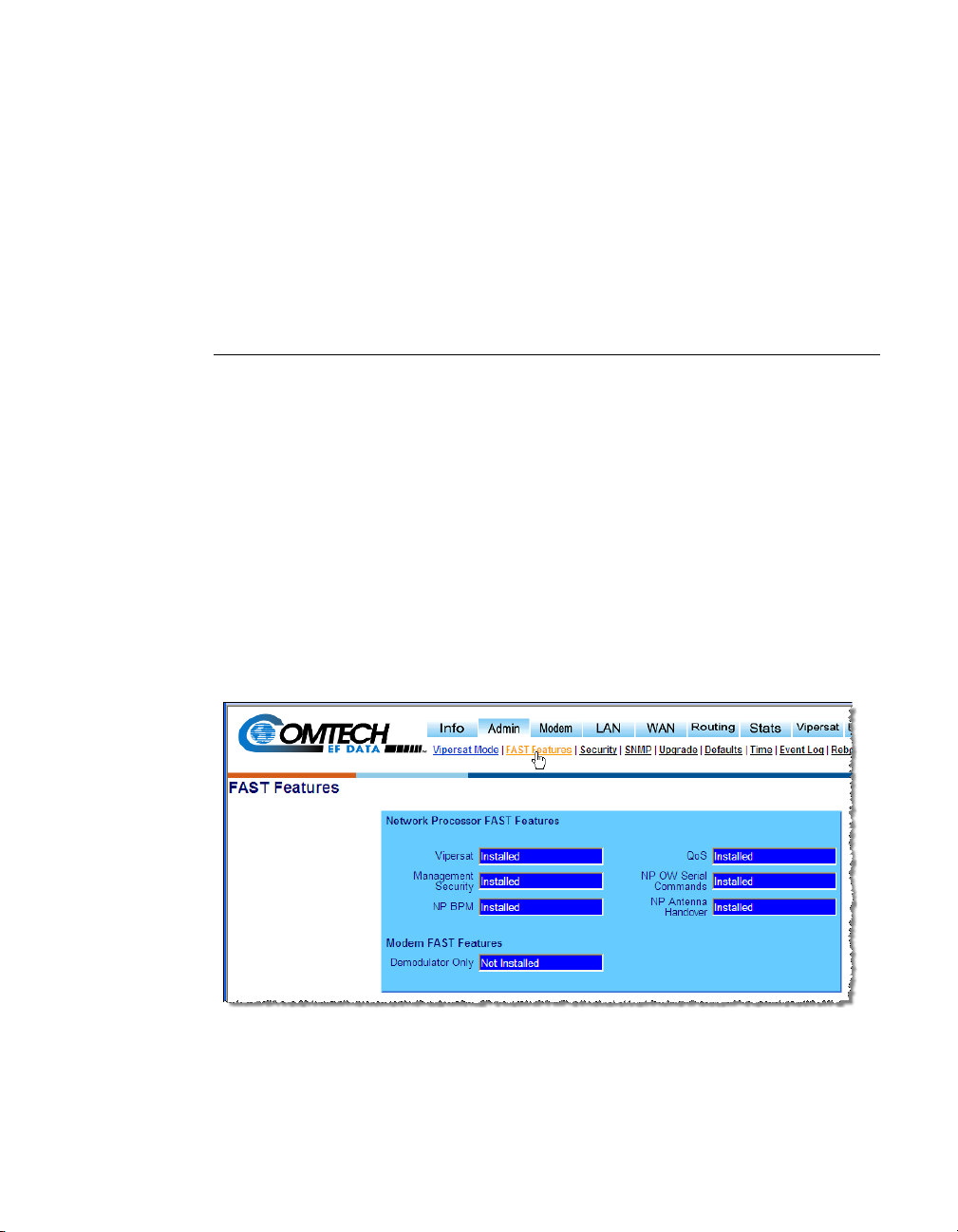
1. From the Admin submenu, select FAST Features, as shown in figure 2-2.
2. Verify whether or not the Vipersat FAST Feature is
Installed (as shown).
The feature codes are entered per customer order prior to shipment from
the factory; however, if the feature displays as
Not Installed, an updated
FAST code will have to be re-entered to enable the Vipersat features.
Figure 2-2
FAST Features Page
2-4 Vipersat SLM-5650A User Guide
Page 29
Initial Configuration
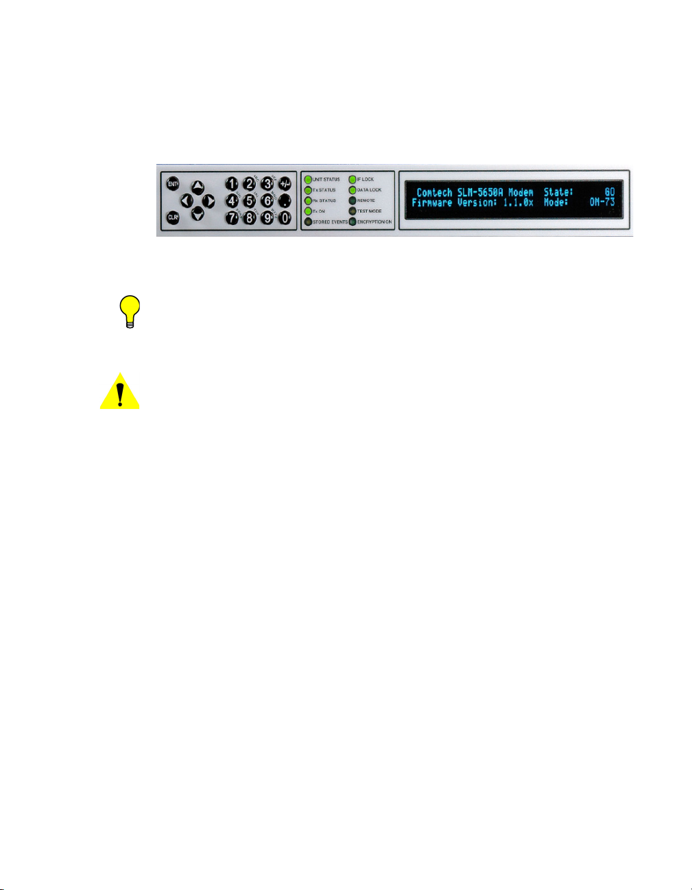
The FAST Feature codes are entered using the front panel of the modem
(figure 2-3). With the keypad, select
Utility -> FAST -> Configuration -> Enter NP Code.
Enter the provided 20 digit code.
Figure 2-3
Tip: The network administrator will have the FAST Feature codes. These are
generated and stored by the unit serial number for the target SLM-5650A.
The target unit’s serial number can be found on the rear of the unit
chassis, or on the FAST code menu.
Caution: Upgraging the FAST features will cause a modem reboot and
reconfiguration of all modem parameters.
Front Panel, SLM-5650A Modem
Set the Vipersat Working Mode
The operating parameters that will be configured in the SLM-5650A are, in part,
determined by the role the modem is to fill in the network, as shown in table 2-1
and table 2-2.
Use the following procedure to configure an SLM-5650A to the network role it
is to fill in a Vipersat network.
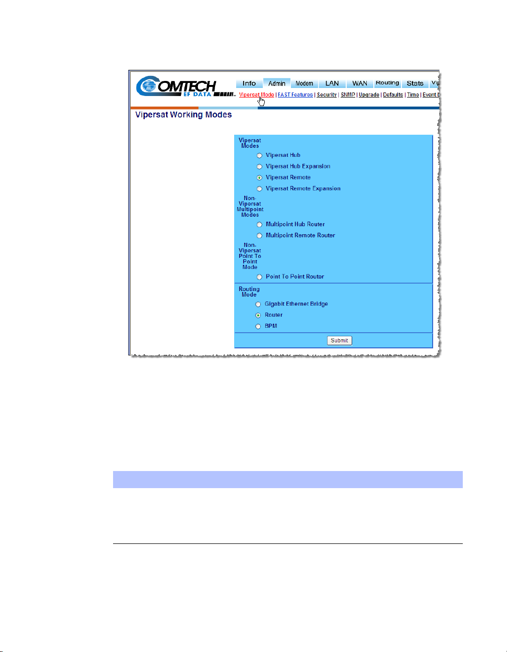
1. Return to the Admin submenu and select Vipersat Mode (figure 2-4).
2. Select the designated Mode by clicking on the corresponding radio button,
then click on the Submit button.
This will set the modem functionality to reflect the selection.
Expansion Unit
When configured as an expansion unit, either as a Hub (switched) or as a
Remote (mesh), the SLM-5650A is set up so that the demod is in SCPC
mode and available as a resource for dedicated communications with the
other end of the satellite link.
Chapter 2 - Quick Start Configuration 2-5
Page 30
Initial Configuration
Figure 2-4
Vipersat Working Mode Page
Once the Vipersat Mode has been set, the Vipersat submenu will be made
available for configuring and setting the Vipersat features according to
table 2-2, below.
Table 2-2
Unit Mode STDMA Auto Switching
Vipersat Hub Available Enabled
Vipersat Hub Expansion Not Available Disabled
Vipersat Remote Available Enabled
Vipersat Remote Expansion (SHOD) Not Available Disabled
Vipersat Feature Configuration
Routing Mode
The Routing Mode defaults to Router, which is the most typical mode for
2-6 Vipersat SLM-5650A User Guide
Page 31

Initial Configuration
Vipersat networks. For networks that call for BPM, see the section
“Routing Mode” on page 3-6.
3. Save the settings to flash by selecting Save from the Main Menu bar.
Set the IP Addressing
1. From the LAN submenu, select Interface to open the LAN Interface page
(figure 2-5).
The MAC Address is displayed as a read-only field.
Figure 2-5
LAN Interface Page
2. Select Single or Dual IP Addressing Mode (default=Single).
Chapter 2 - Quick Start Configuration 2-7
Page 32

Initial Configuration
Choosing Single mode sets the modem to accept all traffic—data, VMS,
and management—that utilizes the Traffic IP Address of the Network
Processor card for this modem. The Management IP Address is ignored.
Selecting Dual mode requires that data and VMS traffic be directed to the
Traffic Address, while CLI, WSI, and SNMP communications must utilize
the Management Address of the NP card. This provides additional security
for remote connections.
Note that Dual mode is also utilized when operating in a redundant
configuration; both the online modem and the offline modem must be set
for Dual IP Addressing. For more information on using the SLM-5650A in
redundancy configurations, refer to the pertinent redundancy switch
Installation and Operation Manual.
Caution: When setting Dual mode, note the address change as the setting will
3. Enter the designated Traffic IP Address and Subnet Mask for this unit.
4. If Dual Mode is being used, enter the designated Management IP
Address and Subnet Mask for this unit.
drop communications to the management interface after submittal.
5. Click on the Submit button
6. Save the settings to flash by selecting Save from the Main Menu bar.
Configure the Route Table
Routing in a Vipersat Network
SLM-5650A Modem Routers operating in Vipersat mode do not use the HDLC
Addressing as described in the SLM-5650A Installation and Operation Manual.
Because satellite networks are often used as extensions for access to services
such as the Internet or the PSTN, they lend themselves quite readily to private
addressing. For example, to provide Internet access to the satellite network, only
the Hub requires a public IP address in order for the entire satellite network that
is controlled by the Hub to have access to the Internet backbone. Utilizing
Network Address Translation (NAT), the administrator can effectively address
the network using a minimum number of static route statements.
2-8 Vipersat SLM-5650A User Guide
Page 33

Initial Configuration
Example:
The IP address 172.16.0.0 is the private address network number for class B
networks. If there is a router at the Hub with a connection to the Internet, the
operator can define the local network as a class B. If the operator splits the
Class B in half and points the upper half toward the satellite, there will be
over 16000 usable addresses at the Hub as well as at the Remotes. For details
on IP addressing, refer to Appendix A, "Network Addressing".
By putting the one route statement “
in the TDM Hub modem, and by using the route statement “
WAN to LAN
” at each of the remote modems, the network will successfully
Remotes 172.16.128.0/17 WAN to LAN”
GW 0.0.0.0/0
route packets. The remotes can then be subnetted as class C networks or
below. Additional routers at the remotes can be added for unusually large
sites, allowing an additional layer of NAT without requiring any more
explicit routing within the Vipersat Modem/Routers.
Refer to the SLM-5650A Modem Installation and Operation Manual for additional information on entering routes.
Creating the Static Routes
The following procedure outlines the basic route structure that the target
SLM-5650A will require for its role in the network. One of the key routes that
must be created is a gateway address for routing the data traffic that is received
by the unit.
1. In the Main Menu bar, select Routes from the Routing submenu
(figure 2-6).
In a Hub configuration, the default route will typically point to a router on the
same LAN as the SLM-5650A Hub unit. In the above figure, that router is specified as the
Next Hop IP 10.1.0.1.
In a Remote configuration, the default route will typically point to the satellite
modem (
toWAN) used for communications back to the Hub.
2. From the Add New Route frame shown in figure 2-6, enter the first route
that will define the default gateway.
The system administrator can supply the information for each field, if
necessary.
In a Hub role, for example, enter the name of the route (e.g., DFG), enter
0.0.0.0 for the destination IP address and 0 for the mask, from the pull
down dialog toLAN/toWAN select toLAN for Ethernet interface, then
enter the IP address of the appropriate router or modem for the next hop.
Chapter 2 - Quick Start Configuration 2-9
Page 34

Initial Configuration
If this Hub unit is providing the TDM outbound, a route statement or
statements defining satellite communications with the Remote units must
be entered as well, as illustrated in the figure. One recommended option is
to enter a single super-route that will handle satellite communications with
all of the remote subnets.
Figure 2-6
Routes Table Page (Hub)
3. Click the Add Entry button.
4. Continue to add entries until all desired routes are entered.
5. Save the settings to flash by selecting Save from the Main Menu bar.
Dynamic Routing with OSPF
For networks that will utilize the Vipersat OSPF (Open Shortest Path First)
feature for dynamic routing, including SOTM roaming applications, additional
routing configuration is required. See the section “Dynamic Routing” on
page 3-40.
2-10 Vipersat SLM-5650A User Guide
Page 35

Initial Configuration
NOTE
Multicast Routing with IGMP
For networks that will utilize the Vipersat IGMP (Internet Group Management
Protocol) feature for multicast routing, additional routing configuration is
required. See the section “Multicast Routing” on page 3-44.
Set the Satellite Modem Configuration
1. Select Config from the Modem submenu to access the Modem
Configuration page (figure 2-7).
2. Set the Transmit parameters for
Modulation as specified by the network administrator.
and
Frequency, Data Rate, FEC, Code Rate,
Figure 2-7
Note: Only Turbo Product Coding is acceptable for FEC when the SLM-5650A
is running in Vipersat mode.
Chapter 2 - Quick Start Configuration 2-11
Transmit Configuration Frame (Hub)
Page 36

Initial Configuration
3. After all Tx parameters are entered, click the Transmit Submit button.
4. Similarly, set the Receive parameters for
Code Rate, and Demodulation as specified by the network administrator
Frequency, Data Rate, FEC,
(figure 2-8).
Figure 2-8
Receive Configuration Frame (Hub)
5. After all Rx parameters are entered, click the Receive Submit button.
6. Save the settings to flash by selecting Save from the Main Menu bar.
2-12 Vipersat SLM-5650A User Guide
Page 37

Initial Configuration
Set the Vipersat Configuration
1. From the Vipersat submenu, select Vipersat to open the Vipersat
Configuration page.
The example shown in figure 2-9 depicts the page appearance for a Hub
unit.
Figure 2-9
Vipersat Configuration Page (Hub)
The unit Role appearance reflects the Working Mode parameter setting
(see “Set the Vipersat Working Mode” on page 2-5) and identifies the role
of the target SLM-5650A.
2. Enter a descriptor for the Node Name.
This a unit indentifier for operator management that is propagated though
the network up to the VMS. The Node Name will appear together with the
modem icon for each unit in the ViperView client.
3. Set the Network ID.
The Network ID that is assigned to the unit defines to what network the
target SLM-5650A will belong. All units used in a common network will
have the same Network ID. This parameter is used by the VMS to identify
Chapter 2 - Quick Start Configuration 2-13
Page 38

Initial Configuration
NOTE
units common to a network and allows the VMS to manage multiple
networks, each with its own unique network ID number.
4. Set the Receive Multicast Address.
This IP address is the multicast address assigned to all Vipersat modem
units in the network that are managed by the VMS server. The Receive
Multicast Address of this SLM-5650A must match the corresponding
Transmit Multicast Address that has been assigned to the VMS in order for
the modem units to receive the maintenance and control packets that are
multicast by the VMS.
5. Set the Managing IP Address.
The Managing IP Address is the IP address of the active VMS server. This
address is set automatically when receiving broadcast messages from the
Hub.
6. Hub Redundancy (Optional)
This field appears for Hub units only.
The Hub Redundancy option provides backup of primary modems (e.g.,
TDM/Burst Controller). When enabled, this setting sends a message
(HeartBeat) to the managing VMS on intervals of 2.5 seconds.
7. Management Security (Optional)
The Management Security option works in conjunction with the Hub
VMS, providing encryption on all messages passed between modem to
modem and active VMS. The keys are set manually on both the VMS and
the modem, and are entered either as a 64 character ASCII hex string or a
passphrase.
Note: VMS version 3.7.1 or greater is required for Management Security.
Caution: During the process of network-wide key distribution and enabling of
encryption, communications may be lost as the STDMA control
messages will be unreadable until all modems in the network are
configured.
It is recommended that each of the Remote units be configured for
Management Security first, and then the Hub units be configured.
This method will reduce the need for on-site personnel during feature
implementation.
2-14 Vipersat SLM-5650A User Guide
Page 39

Initial Configuration
Set the Home State
1. From the Vipersat submenu, select Home State to open the Home State
Configuration page (figure 2-10).
2. Click the Set Current Config As Home command button in the lower
portion of the page to set the current configuration as the Home State. This
pulls the current Tx and Rx settings of the base modem and displays them
here.
Figure 2-10
Home State Configuration Page
3. If any parameters require modifications, change the values then click the
Force Modem to Home State command button. This will push the home
state parameters that are displayed to the base modem.
4. Save the settings to flash by selecting Save from the Main Menu bar.
Chapter 2 - Quick Start Configuration 2-15
Page 40

Initial Configuration
This completes the initial configuration of an SLM-5650A modem/router from
the factory default settings to a functioning, Vipersat-enabled unit. Additional
configuration parameters remain to be set depending on the network requirements for the specific customer application.
Proceed to Chapter 3, "Using the Web Server Interface (WSI)," for additional
details on configuring the target Vipersat SLM-5650A.
2-16 Vipersat SLM-5650A User Guide
Page 41

C
HAPTER
USING THE WEB SERVER INTERFACE (WSI)
General
This chapter describes the use of the WSI for configuring and monitoring the
SLM-5650A Modem Router in a Vipersat network. Each web page related to an
SLM-5650A operating in Vipersat mode is presented, along with a detailed
description of the available commands. For descriptions of all other screens,
refer to the SLM-5650A Installation and Operation Manual.
Web (HTTP) access to the SLM-5650A is provided through the NP (Network
Processor) card Ethernet traffic switch, and requires login with password. The
physical LAN connection is made to one of the following RJ-45 interfaces:
• When operating with Router Mode set to Router, one of the four Ethernet
ports, 1–4, on the NP card should be used.
• When operating with Router Mode set to BPM (Bridge Point-toMultipoint), network management can only be performed using the J5
Ethernet port on the base modem.
The pages presented in this document are as they appear when the SLM-5650A
is accessed using the Microsoft Internet Explorer web browser.
A Web connection is made by entering the target SLM-5650A NP IP address
into the browser address field. The factory default IP address for a Vipersatenabled unit is
prompt. The factory defaults are:
Chapter 3 - Using the Web Server Interface (WSI) 3-1
192.168.1.177/24. The SLM-5650A responds with a Login
Page 42

General
Login: comtech
Password: comtech
Once the operator has logged in, the Network Processor splashscreen is
displayed as shown in figure 3-1.
The WSI is an easy to use interface for configuring and monitoring all aspects
of the SLM-5650A. By rolling the cursor over the Main Menu bar at the top of
the page, the user can navigate to the desired page by selecting from the nested
submenu links that appear.
Figure 3-1
3-2 Vipersat SLM-5650A User Guide
Network Processor Splashscreen
Page 43

Menu Descriptions
NOTE
This section details the WSI menu pages, and briefly discusses the function of
each of the parameters available on each menu page.
Main Menu Bar
The WSI Main Menu Bar, shown in figure 3-2, allows configuring both the
modem and router functions of the target SLM-5650A Network Processor.
Menu Descriptions
Note: The Vipersat menu item will only be displayed if the target SLM-5650A
A Vipersat SLM-5650A is normally shipped from the factory with the Vipersat
FAST feature option already installed. This can be verified by checking that
Vipersat appears in the Main Menu bar, as shown in Figure 3-2. Alternatively,
this can be checked via the modem front panel under
Options
Each Main Menu item contains a nested submenu that will appear by performing a mouseover on that menu item. Clicking on a submenu item will open the
associated page.
has had the Vipersat option installed as described in the section “FAST
Features” on page 3-7.
Figure 3-2
.
Main Menu Bar
Utility: FAST ->View
Common Menu Commands
The following common menu commands are executed as described below.
Chapter 3 - Using the Web Server Interface (WSI) 3-3
Page 44

Menu Descriptions
Save Parameters to Permanent Storage
To Save the current configuration to permanent Flash storage, select Save from
the Main Menu bar, as shown in figure 3-3. Click on the Save Now button to
initiate the save process, then click OK to confirm and complete the process.
This command saves all data that has been entered from any of the web pages
since the last save operation occurred.
Figure 3-3
Save Configuration Command
Exiting a page after parameters have been changed without saving does not
mean that the changes are not applied. However, if these changes are not saved
prior to a system reset or power cycle, they will be lost.
Log Off
To terminate the WSI session and disconnect from the NP, select the Logoff
command from the Info submenu, as shown in figure 3-4. Confirm the Log off
request by clicking on the Yes, log off now button.
Figure 3-4
NP Logoff Command
3-4 Vipersat SLM-5650A User Guide
Page 45

Menu Descriptions
Information
The specific firmware image versions and system up time for the Network
Processor can be viewed by performing a mouseover on Info in the Main Menu
bar and selecting Home from the submenu, as shown in figure 3-5. This information is useful, for example, when planning or performing upgrade operations
for a unit.
Figure 3-5
Home Page
Administration
The Admin Menu provides access to the major Administration features and
commands (figure 3-6) for the SLM-5650A. The specific submenu items that
are described here for a Vipersat network are Vipersat Mode and FAST
Features.
Vipersat Mode
Select Vipersat Mode from the Admin submenu, as shown in figure 3-6. This
setting determines whether the target SLM-5650A is to function as a Vipersat
Remote or as a Vipersat Hub (and whether or not it is an Expansion unit) in the
Vipersat satellite network. The Non-Vipersat Mode choices are not applicable
when configuring a modem for deployment in a Vipersat network.
Chapter 3 - Using the Web Server Interface (WSI) 3-5
Page 46

Menu Descriptions
NOTE
The choice that is made here will determine the role that this SLM-5650A will
perform in the network, and what type of commands and functions it will
receive from the VMS. Refer to table 2-1 for a breakdown of network roles and
related functions and features.
Note: If Vipersat Mode does not appear in the menu, the Vipersat FAST Code
has not yet been installed in this unit. The FAST Code for the Vipersat
option must first be re-entered as described in the next section.
Selecting the modem to be an Expansion device, either as a Hub (switched) or
as a Remote (mesh), sets the demod of the SLM-5650A to operate in dSCPC
mode, available as a resource for dedicated communications with the other end
of a satellite link.
Figure 3-6
Working Mode Page
Routing Mode
The Routing Mode defaults to Router. Another option for Vipersat networks is
the BPM routing (brouter) mode that offers additional flexibility and scalability
3-6 Vipersat SLM-5650A User Guide
Page 47

Menu Descriptions
of the satellite network by providing a combination of routing and bridging
functions. Note that this option is only available if the NP BPM FAST feature
has been installed on the modem/router.
When BPM (Bridged Point-to-Multipoint) is selected as the routing mode, the
function of the five Ethernet ports changes: NP module ports 1 through 4
change from routed Layer 3 traffic and management use to bridged Layer 2 traffic; base modem port J5 changes from remote control connector to routed Layer
3 traffic and management use.
Caution: When using a remote connection to change the Routing Mode from
Router to BPM, ensure that the Ethernet connection that is being
utilized is cabled to port J5. If the connection is utilizing one of the
four ports on the NP module, connectivity with the modem will be lost
as soon as the change is submitted.
Additional information about the BPM feature can be found in the SLM-5650A
Installation and Operation Manual.
Ensure that the Vipersat Working Mode is set as specified for this unit. If it is
not, change the setting by selecting the appropriate radio button(s) and clicking
the Submit button. The modem unit will automatically be set up for the appropriate configuration parameters based on this setting, thus simplifying deployment.
FAST Features
From the Admin submenu, select FAST Features to display the FAST Feature
page shown in figure 3-7.
This read-only page displays the status for both the Network Processor and the
Modem FAST Features—Installed or Not Installed.
Chapter 3 - Using the Web Server Interface (WSI) 3-7
Page 48

Menu Descriptions
Figure 3-7
FAST Features Page
Verify whether or not the Vipersat FAST Feature is Installed (as shown). The
codes are entered per customer order prior to shipment from the factory;
however, if the feature displays as
Not Installed, an updated FAST code will
have to be re-entered to enable the Vipersat features.
The FAST Feature codes are entered using the front panel of the modem
(figure 3-8). With the keypad, select
Utility: FAST -> Configuration -> Enter NP Code.
Enter the 20 digit code that is provided by either the network administrator or
Comtech Vipersat Networks Customer Support.
Figure 3-8
Tip: The FAST Feature codes are generated and stored by the unit serial
number for the target SLM-5650A. The target unit’s serial number can be
found on the rear of the unit chassis, or on the FAST code menu.
Caution: Upgraging the FAST features will cause a modem reboot and
reconfiguration of all modem parameters.
Front Panel, SLM-5650A Modem
To maintain any parameter changes in flash memory, select Save from the Main
Menu bar.
3-8 Vipersat SLM-5650A User Guide
Page 49

Vipersat Configuration
Mouseover Vipersat in the Main Menu Bar, as shown in figure 3-9, to display
the submenu used for configuring the Vipersat features and functions for the
SLM-5650A.
The following sections describe each submenu in detail.
Vipersat
Selecting the first item in the submenu opens the Vipersat configuration page.
The display will vary depending upon whether the Working Mode is defined as
a Hub unit or a Remote unit. The example shown in figure 3-9 portrays a Vipersat Hub.
Vipersat Configuration
Figure 3-9
An example of a Vipersat Remote is shown in figure 3-10. Much of the parameters that are displayed for a Hub unit are also common for a Remote. However,
the Hub display includes the Hub Redundancy feature whereas the Remote
display includes the SOTM feature. These parameters are described below.
Chapter 3 - Using the Web Server Interface (WSI) 3-9
Vipersat Configuration Page (Hub)
Page 50

Vipersat Configuration
Figure 3-10
Figure 3-10 Vipersat Configuration Page (Remote)
Vipersat Role
The Role field is display only, reflecting the Vipersat Working Mode setting that
was configured earlier under Administration. The chosen mode is also identified
by the Vipersat label that is displayed in the upper left portion of the page—
“Vipersat Hub” in this example.
Node Name
The Node Name entry is used to assign a designator to the SLM-5650A that
will identify this unit within the network. Any combination of up to 22 characters can be entered.
This name is displayed within the VMS ViperView, the graphical network
management interface for Vipersat networks.
Network ID
The Network ID that is assigned to the unit defines to what network the target
SLM-5650A will belong. All units used in a common network will have the
same Network ID. Enter a value between the range of 0–255.
3-10 Vipersat SLM-5650A User Guide
Page 51

Vipersat Configuration
NOTE
The Network ID is used by the VMS to identify units that are common to a
network and allows the VMS to manage multiple networks, each with its own
unique Network ID number.
Receive Multicast Address
The Receive Multicast Address is the multitcast IP address assigned to all
SLM-5650A units in the Vipersat network that are managed by the VMS server.
This address must match the VMS Transmit Multicast Address.
When the SLM-5650A receives a multicast from the VMS server, it receives
maintenance and control packets, including the server’s IP address. The SLM5650A responds to the VMS server with a unicast containing its current configuration data, including the SLM-5650A’s IP address. When the VMS receives
the unicast response, it registers the SLM-5650A on the network.
Enter the Receive Multicast Address as assigned by the network operator/
administrator.
Managing IP Address
The Managing IP Address parameter corresponds to the IP address of the
server running the VMS.
This address is sent out with the VMS multicast to all of the Vipersat units and
will be automatically updated during the registration process. The SLM-5650A
sends a unicast registration request to the managing address every 60 seconds
when requesting initial registration on the VMS network. Later, the SLM5650A uses this address to send switch requests, network health status
messages, etc. to the managing VMS server.
Note: The managing address will be set automatically if the Receive Multicast
Address is configured correctly and the modem is receiving the
announcement multicast message. However, the modem WILL NOT
send its registration request message until this address is set.
This managing address is automatically updated on a periodic basis for modems
that are newly enabled, incorrectly set, or following VMS changeovers (redundancy switching).
Heart Beat
This menu item appears for the Hub modem only.
The Heart Beat feature is a redundancy heart beat message for primary Hub
units that provides the option for a periodic communications check message to
be sent from the Hub modem to the VMS for backup recovery in N:M redun-
Chapter 3 - Using the Web Server Interface (WSI) 3-11
Page 52

Vipersat Configuration
NOTE
dancy (protected) configurations. The message interval is set by the managing
VMS which uploads it to the modem.
Activate this feature by selecting the Enabled radio button.
Management Security
Management Security is an optional Vipersat feature that provides encryption
on all VMS management messages passed between the VMS and the network
modems. When enabled, the VMS and all of the network modems must utilize a
common Encryption Key that is manually set on each. The key can be entered
either as an ASCII hex string of exactly 64 characters, or as a passphrase
consisting of up to 63 characters.
For modems that operate with Management Security, Enable this feature and
enter the Encryption Key that has been defined for the network.
Note: VMS version 3.7.1 or greater is required for Management Security.
Caution: During the process of network-wide key distribution and enabling of
encryption, communications may be lost as the STDMA control
messages will be unreadable until all modems in the network are
configured.
It is recommended that each of the Remote units be configured for
Management Security first, and then the Hub units be configured.
This method will reduce the need for on-site personnel during feature
implementation.
SOTM
This feature appears for Remote units only.
For Remotes that are not utilized in an SOTM (Satcom-On-The-Move) network,
this feature will be displayed at the bottom of the page as Disabled, as shown in
figure 3-10 above. When a Remote has been enabled for SOTM via a ROSS
unit, the feature can be disabled from the WSI Vipersat page by clicking on the
Disable SOTM button (figure 3-11). Note that the disable command will not be
executed until a Save operation is performed and the unit is rebooted.
Figure 3-11
3-12 Vipersat SLM-5650A User Guide
Disable SOTM for Remote
Page 53

Vipersat Configuration
To maintain any parameter changes in flash memory, select Save from the Main
Menu bar.
STDMA Mode
The STDMA parameters for this SLM-5650A are accessed by selecting
STDMA from the Vipersat submenu.
The fields in the STDMA configuration page will vary depending on the function the target SLM-5650A performs in the network. The page shown in
figure 3-12 is from an SLM-5650A serving as a Hub in the network.
Figure 3-12
Chapter 3 - Using the Web Server Interface (WSI) 3-13
STDMA Page (Hub, Dynamic Cycle mode)
Page 54

Vipersat Configuration
For comparison, the STDMA menu for an SLM-5650A operating as a Remote
unit is shown in figure 3-13. Note that the configuration items for the Remote
screen are a small subset of those for a Hub.
Figure 3-13
STDMA Page (Remote)
Allocation Method
This parameter field is only displayed if the SLM-5650A is being used as a Hub
in the network, and provides the functionality for the STDMA Burst Controller.
Vipersat STDMA has five modes of operation:
•Fixed — all Remotes get the same data slot time (slot size) in the cycle,
regardless of activity. Cycle time is fixed also.
• Dynamic Slot — data slot time of Remotes vary according to activity,
cycle time does not.
• Dynamic Cycle — slot time and cycle time vary according to activity of
Remotes.
•GIR (Guaranteed Information Rate) — each Remote always has at least
the minimum data slot size when needed, and cycle time is variable up to a
maximum of one second.
• Entry Channel — Remotes run in SCPC mode, but STDMA is used for
maintenance and control channel.
The Hub can be configured to operate in one of the five modes by selecting the
Allocation Method from the pull-down menu, as shown in figure 3-14.
3-14 Vipersat SLM-5650A User Guide
Page 55

Vipersat Configuration
Figure 3-14
Hub Type Allocation Menu
This selection determines whether available bandwidth will be a static (fixed)
assignment, or whether bandwidth allocation will be dynamic with automatic
switching to dynamically optimize bandwidth utilization.
1 – Fixed
In the Fixed mode, all Remotes have the same data slot size regardless of type
of traffic or load. This mode minimizes the amount of jitter between Remote
transmission times, and is useful for tuning STDMA as well as for troubleshooting purposes.
2 – Dynamic Slot
In the Dynamic Slot mode, slot size is adjusted each cycle depending on the
activity during the previous cycle. The slot size for each Remote is computed
based on the time (at the current data rate) needed to transmit all the bytes in
queue. If the result is less than the minimum slot size or more than the maximum slot size, the slot is adjusted accordingly. This mode allows the burst
controller to provide additional slot time in the cycle to Remotes with higher
traffic demands, increasing throughput and alleviating congestion.
3 – Dynamic Cycle
In the Dynamic Cycle mode, available bandwidth is allocated to Remotes
proportionally based on their current bandwidth needs. The bandwidth requirements are determined by the number of bytes in queue for each Remote divided
by the total number of bytes in queue for all Remotes, and results in the percentage of bandwidth to be allocated for each Remote. This mode provides
improved efficiency of STDMA due to faster cycle times during periods of light
traffic demands, thus providing minimum latency for the current load.
4 – GIR
In the GIR mode, the initial computed slot size value is the same as in the
Dynamic Cycle mode except there is no maximum limit. After all Remotes have
Chapter 3 - Using the Web Server Interface (WSI) 3-15
Page 56

Vipersat Configuration
NOTE
been assigned slots, the burst map is checked to see if the total cycle length
exceeds one second. If not, then all requirements are satisfied and the burst map
is complete. However, if the cycle is greater than one second, then the slots are
adjusted proportionally so that all Remotes receive at least their guaranteed rate
plus whatever excess is still available.
GIR mode allows guaranteed information rates to be set for each Remote in the
group. When the one second restriction is exceeded, Remotes without a specified GIR are reduced to the global minimum slot size and the remaining bandwidth is distributed to Remotes that have been assigned a GIR rate, thus
ensuring additional bandwidth to these units when needed.
Note: GIR allocations are restricted so that assigned GIR totals cannot exceed
the available bandwidth. This ensures proper bandwidth allocation when
the network is overloaded.
The GIR setting for each Remote is specified using the STDMA Remote Policies screen (refer to the section “ECM Remotes” on page 3-25). When
combined with Auto switching, GIR allows trigger points to be set where the
Remote will jump out into SCPC mode. This is done using the Load Switch
setting. Note that, for this function, Load switching must be Enabled on this
Hub unit, and corresponding Remote modems must be configured with Load
switching Enabled as well. Also, the settings for Step Up and Step Down
Threshold values should be adjusted as necessary for the application.
5 – Entry Channel
The Entry Channel mode provides Remotes in the group with a shared channel
in which they can gain initial access to the network. Since very small STDMA
data rates are required in this configuration, a larger number of Remotes can
share the cycle. As soon as the Hub receives an STDMA ACK from the
Remote, it initiates an immediate switch to SCPC mode based on the policy set
for that Remote. Note that the switch occurs as soon as the Hub receives an
ACK even though there may not be traffic at that time. The persistence of the
link will be determined by the unit’s flag settings.
When choosing Entry Channel as the Hub type for the STDMA Controller, the
Load switching feature must be Enabled on this Hub unit, and switching policies for the Remotes must be configured (refer to the section “ECM Remotes”
on page 3-25). Corresponding Remote modems must be configured with Load
switching Enabled. Note that the settings for Step Up and Step Down Threshold
values should be adjusted as necessary for the application.
This mode is designed to accommodate the needs of a Remote that will not be
continuously connected to the network, but which has the need to be able to
make an on-demand connection when required, such as in a mobile application.
In the event of a power outage, Entry Channel provides a bandwidth-efficient
3-16 Vipersat SLM-5650A User Guide
Page 57

Vipersat Configuration
method for remotes with low latency requirements to re-enter the network once
power is restored.
Refer to Appendix B “Automatic Switching” for additional information on how
each of the bandwidth allocation modes functions and the parameters used to
calculate the commands for each mode.
Acquisition Mode
The SLM-5650A modem/router offers two modes of choice for the Hub BC to
obtain acquisition of—detect and lock onto—the burst transmission from each
Remote in the group: Standard and Long.
Figure 3-15
Hub STDMA Acquisition Mode
Standard mode uses an uncoded preamble signature and results in a shorter
Preamble Time:
Data Rate = 64 to 447 kbps Preamble = 30 ms
Data Rate >
448 kbps Preamble = 20 ms
Long mode uses a combination of uncoded and coded portions of the signature
that provides additional reliability, but results in a longer Preamble Time, as is
illustrated with the following two examples:
Data Rate = 256 kbps Preamble = 26 + 79 = 105 ms
Data Rate = 3 Mbps Preamble = 2 + 38 = 40 ms
Note that, as a consequence of a longer preamble, the time period available for
data transmission is lessened. However, this trade-off is acceptable in those
applications where the priority is given to increased reliability.
Standard mode is appropriate, for instance, when Entry Channel is used as the
allocation method. Long mode is appropriate for a Hub controller whose
Remotes are allocated larger slot sizes, and thus would suffer greater data loss
per burst cycle with acquisition failure.
Group ID
The STDMA Group ID number defines a group of equipment (both Hub and
Remote units) that will respond to the output of a single STDMA burst controller. This group is addressable within a network which, in turn, is defined by the
Network ID number assigned to the SLM-5650A.
Chapter 3 - Using the Web Server Interface (WSI) 3-17
Page 58

Vipersat Configuration
NOTE
Allocation of bandwidth is shared among the Remotes in an STDMA group.
Depending on the number of Remotes in a network, a Hub may have multiple
burst controllers, each with its own set of Remotes. This is accomplished by
assigning a unique Group ID number to each controller and its associated
Remotes.
Note: The STDMA Group ID number and the Network ID number are indepen-
dent. There can be multiple STDMA groups within a single network.
To set the Group ID for an SLM-5650A, enter the specified number for the
associated group; range is 1–255 (figure 3-16). Click the Submit button.
Figure 3-16
Group ID field
Cycles Per Burst Map
This parameter, which appears for all Hub types except Dynamic Cycle and
GIR, displays the number of spin cycles that will occur prior to each broadcast
of the Burst Map by the burst controller to the Remotes. One cycle is the
amount of time it takes for all Remotes in a group to burst on the common channel. The burst map provides each Remote with its allocated bandwidth and position in the cycle.
For Dynamic Cycle and GIR configurations, the number of cycles is automati-
cally set to one in order to ensure optimum performance for these Hub types.
To modify this parameter from the Hub SLM-5650A, enter a value from 2–20 in
the Cycles Per Burst Map field, then click the Submit button as shown in
figure 3-17.
Figure 3-17
3-18 Vipersat SLM-5650A User Guide
Cycles Per Burst Map field
Page 59

Vipersat Configuration
Preamble Time
This parameter, which appears in all Hub configurations, displays the current
Slot Preamble size in milliseconds for the Remotes in the group. The Preamble
is the period between when the Remote begins to transmit (sends an ACK) to
the Hub and when the first data packet is sent. This allows time for signal lock
to occur before data is sent, thus preventing data loss.
The Preamble Time is automatically set based on internal calculations that
correlate transmit burst acquisition preamble times to STDMA transmit data
rates and Acquisition Mode selection. Standard Acquisition Mode uses an
uncoded signature. Long Acquisition Mode uses both uncoded and coded
portions of the preamble, as is shown for the example in figure 3-18. The sum
of these two values equals the total Preamble Time; in this case, 40 ms.
Figure 3-18
Slot Preamble Time display
Guard Band
This parameter, which appears for all Hub configurations, displays the current
length of the Slot Guardband in milliseconds for the Remotes in the group. The
Slot Guardband is the amount of time between the point when one Remote
completes transmitting data and the point when the next Remote in the cycle
begins transmitting. This prevents the Remote from overrunning the next terminal in the cycle. The setting for this parameter should be obtained using the
Vipersat STDMA Calculator. Typically, a value of 30 ms is sufficient.
Tip: Contact a Comtech Vipersat Networks representative for a copy of the
latest Viper Calculator.
To modify this parameter on a Hub unit, enter a value from 0–250 in the Guard
Band field, then click the Submit button. The value represents time in millisec-
onds.
Figure 3-19
Slot Guardband field
Slot Data Length
This menu item displays the Slot Data Length in milliseconds as well as in
bytes, and represents the amount of data that can be transmitted or received in
Chapter 3 - Using the Web Server Interface (WSI) 3-19
Page 60

Vipersat Configuration
NOTE
one spin of the STDMA cycle by each of the Remotes belonging to that group.
This is the amount of time that the Remote is provided to send data in the cycle.
Depending on the Hub type that is defined for the modem, the appearance of
this parameter will vary:
• Fixed – Slot Data Length
• Dynamic Slot – Nominal Data Length, Minimum Data Length
• Dynamic Cycle – Maximum Data Length, Minimum Data Length
• Entry Channel – Slot Data Length, Minimum Data Length
• GIR – Minimum Data Length
On a Hub unit, enter the specified value(s) in milliseconds within the allowed
range, as shown in figure 3-20.
Note: When setting the Minimum Data Length, ensure that the slot length is not
less than the maximum MTU (1500 bytes), as this would prevent large
data packets from transmitting and result in the loss of data.
Figure 3-20
Slot Data Length (Dynamic Cycle)
Burstmap Multicast IP
This parameter is used to define the IP address for the Burstmap Multicast that
is sent out by the STDMA burst controller at the Hub to all of the associated
Remotes in that group. This address must be the same for all members of the
group. The burst map is a proprietary message sent from the Hub to all
Remotes, at regular intervals, specifying the relative start time and duration for
each terminal to transmit.
To set this parameter, enter the specified Multicast IP address (figure 3-21),
then click the Submit button.
Figure 3-21
3-20 Vipersat SLM-5650A User Guide
Burstmap Multicast IP field
Page 61

Vipersat Configuration
Power Hunt
Power Hunt is a transmission power control feature for the Remote modulator
that functions while the Remote is in STDMA mode. This parameter provides
compensation for instances when the initial (baseline) power value is insufficient or during periods of impaired transmission, and assists in maintaining
return link integrity.
When a predetermined number of consecutive burst acknowledgements from
the Remote are missed at the Hub, the power output is increased in 1 dB increments, up to a maximum of 3 dB. The value specified for the Power Hunt
parameter (range is 0-3) determines the maximum power increase for this
Remote.
Figure 3-22
Power Hunt field
The Power Hunt function is disabled when the Remote switches from STDMA
to SCPC mode, where the DPC feature is then applied. However, the Power
Hunt value at the time of the switch is carried over as the initial DPC offset
value. When switching back to STDMA from SCPC mode, the last DPC offset
will be applied as the power hunt (delta) value.
A modem reboot or forced revert will clear the DPC offset and reset it to 0 dB.
Outbound IP
This parameter, which appears for all Hub configurations, displays the current
TDM Outbound IP address. This specifies the Hub device that is supplying the
TDM outbound carrier to the satellite (typically a SLM-5650A). Specifying this
address is necessary when configuring a Hub that utilizes a burst controller that
is a separate device from the TDM modem.
This address must also be defined when the DPC feature is implemented for a
network. Note that the Outbound IP address will be the same as the burst
controller address when the TDM modem and the burst controller are the same
device.
To define the TDM Outbound IP address, enter the address of the TDM
modem unit and click the Submit button. The dialog in figure 3-23 shows this
Hub parameter field.
Chapter 3 - Using the Web Server Interface (WSI) 3-21
Page 62

Vipersat Configuration
Figure 3-23
Outbound IP field
Automatic Remote Removal
The Automatic Remote Removal feature appears on the STDMA page when
the Unit Role is Hub, and is used to define the removal parameters for the
Remotes that belong to the STDMA group for the Hub Burst Controller.
Figure 3-24
When Enabled, the value entered in the Removal Timeout Cycles field specifies the amount of time (seconds) with no communications from the Remote to
the Hub before that Remote is removed from the Burstmap. If communications
are lost for this period of time, the Remote is removed from the STDMA group,
and the bandwidth resources it had been allocated are then made available for
use by the other Remotes remaining in the group.
This feature is useful, for example, in an SNG application where a mobile
Remote has finished its assignment and has shut down.
Automatic Remote Removal
When a Remote has been removed from the STDMA group, the value that is
entered for the Removal Retry Cycles parameter specifies the amount of time
(seconds) that is allowed to pass before a retry attempt is made to return the
removed Remote to the group. The Remote is re-entered into the burst map
cycle; if the Remote does not burst back (ACK) to the Hub Burst Controller, it
is once again removed from the Burst Map.
This allows, again using a mobile Remote as an example, shutting down the
Remote at one location, moving it to a new location, and then automatically reestablishing a connection to the satellite network.
3-22 Vipersat SLM-5650A User Guide
Page 63

Vipersat Configuration
Remote List Table
The Remote List Table appears on the STDMA page when the Unit Role is
Hub. The screen example shown in figure 3-25 is typical of the appearance for
all allocation methods except for GIR and ECM, which are depicted in
figure 3-26 and figure 3-27, respectively.
Figure 3-25
STDMA Remote List Table
This feature is used to assign and display the Remotes that belong to the
STDMA group for the Hub burst controller. Remote units can be added/deleted
to/from the list, and their status in the burst map can be set—Enabled or
Disabled. Modifications to existing entries can be made by editing the desired
field(s) and submitting the changes.
Chapter 3 - Using the Web Server Interface (WSI) 3-23
Page 64

Vipersat Configuration
Figure 3-26
Figure 3-27
Remote List Table, GIR Hub
Remote List Table, ECM Hub
Add Remote to STDMA Group
In the Add New Entry section, enter the Station Name for the Remote unit and
the IP Address, then click the Add Entry button. The new Remote will be
listed in the table as a member of the STDMA group.
Once a Remote has been added to the STDMA group, its status in the group is
displayed on the Vipersat Stats page (see “STDMA Hub Statistics” on
page 3-27).
3-24 Vipersat SLM-5650A User Guide
Page 65

Vipersat Configuration
Set Remote Policies—GIR and ECM
The STDMA page for GIR and ECM Hub types allows the configuration of
each Remote for specific data switching conditions.
GIR Remotes
As shown in figure 3-26, two additional parameters—GIR and GIR Switch
Rate—are settable in the table for the GIR Remotes. Note that, above the table,
data rate and bandwidth guidelines for setting the GIR values are provided as
reference to assist the user with configuration of these parameters.
Set the Switch Rate to a value greater than the GIR to allow the Remote to be
automatically switched out of STDMA and into SCPC mode when traffic
exceeds the GIR. A switch rate of 0 (zero) will prevent the Remote from being
switched.
Click the Submit Changes button following any parameter modifications.
ECM Remotes
The SCPC Data Rate and Switch Type parameters are two additional settings
that can be configured in the table for the ECM Remotes, as shown in
figure 3-27.
Set the SCPC Data Rate to the desired value (kbps) that will be the starting point
for communications. Set the Switch Type as follows:
• Type 0 (zero) corresponds to Load Switching.
• Types 64 through 255 are user-defined, and must match VMS policies.
When choosing Load Switching as the switch type, the associated Remote must
have the Load Switching feature Enabled (see the section “Vipersat Switching”
on page 3-28).
Click the Submit Changes button following any parameter modifications.
Remove Remote from STDMA Group
From the STDMA Hub page, the Delete Entry feature is available as shown in
figure 3-28, allowing a Remote to be removed from the table list for this Hub
burst controller.
Enter the Index number from the table for the Remote station to be removed and
click the Delete Entry button.
Chapter 3 - Using the Web Server Interface (WSI) 3-25
Page 66

Vipersat Configuration
Figure 3-28
Delete Table Entry field
Enable/Disable Remote
Included in the Remote List Table is the Status column displaying whether the
station is currently Enabled or Disabled (figure 3-29). This feature can be used
to easily place a Remote in or out of the burstmap without having to perform
Add/Delete Entry procedures.
Figure 3-29
Remote Status selection
Change the status setting by clicking on the pull-down arrow and selecting the
other choice. Then click on the Submit Changes button.
To maintain any parameter changes in flash memory, select Save from the Main
Menu bar.
STDMA Statistics
Selecting Stats from the Vipersat submenu displays the STDMA Statistics for
either Hub or Remote, based on the Vipersat Mode setting for this modem, as
shown in figure 3-30 and figure 3-31.
3-26 Vipersat SLM-5650A User Guide
Page 67

Vipersat Configuration
STDMA Hub Statistics
The STDMA-Hub Statistics page (figure 3-30) provides information on burst
cycle intervals, number of missed and received ACK’s per Remote, and the
receive byte counts per burst.
Figure 3-30
STDMA Hub Statistics Page
Statistics in the received ACK from each Remote are monitored by the Burst
Controller. These statistics report the fill status of the burst data slot for each
Remote. The Burst Controller builds a table of the group and calculates the relative data byte count for each Remote. It then calculates the length of the data
slot for each Remote based on the Minimum Slot Length plus a percentage of
the Available Bandwidth. Idle Remotes receive a data slot equal to the Minimum Slot Length.
The dynamic range of STDMA is a function of the difference between the
Nominal Data Length and the Minimum Data Length parameters. These parameters are operator selectable. The speed with which STDMA reacts to changes
in dynamic load is a function of the Cycles per Burst Map parameter, which is
also operator selectable.
An informative indicator on the STDMA Hub Statistics page is the Status of the
Remotes that appears in the first column to the right of the IP Address column.
The Remote status is displayed using one or multiple of the following:
•U = Used – This Remote is being used in the burst map.
Once a remote has been added to the STDMA group, this status will
always be displayed.
•B = Burstmap – This Remote is currently in the burst map.
This status will be displayed unless the remote has been removed (R),
disabled (D), or switched (S) out of the STDMA burst map.
•R = Removed – This Remote is currently removed from the burst map.
When displayed, this status indicates that the Hub has removed this remote
from the burst map due to a communications fault.
Chapter 3 - Using the Web Server Interface (WSI) 3-27
Page 68

Vipersat Configuration
•D = Disabled – This Remote is currently disabled and is not in the burst
map.
This status will be displayed when a remote is manually disabled by the
operator or administrator.
•S = Switched – This Remote is currently switched into SCPC mode.
When displayed, this status indicates that the VMS has automatically
switched the remote out of the burst map and into SCPC operation.
•H = Home State Revert – This Remote is not currently receiving burst
maps. When a remote, stuck in SCPC mode by failure to receive a VMS
revert command, sees the burst map with this flag set, it will automatically
revert to its home state and STDMA mode.
•A – This Remote has not sent an acknowledgement to the burst controller.
The Hub statistics are useful for tuning the Burst Controller. Preamble adjustments, up or down, are made using the missed ACKs statistic; a preamble and/
or guardband that is too short will result in an accumulation of missed ACKs.
The “Cont. Missed ACKs” column represents continuous—the number of
sequential ACKs missed.
STDMA Remote Statistics
The STDMA Remote Statistics page (figure 3-31) provides information on
Burst Maps received, Preamble Time, Guard Band period, and Slot Time for the
Remote modem.
Figure 3-31
The Remote statistics are useful for determining the status of remote terminal
reception and troubleshooting burst transmission problems.
STDMA Remote Statistics Page
Vipersat Switching
One of the most powerful features of the Vipersat SLM-5650A is the capability
to perform automatic switching between STDMA mode and SCPC mode based
3-28 Vipersat SLM-5650A User Guide
Page 69

Vipersat Configuration
on bandwidth demand. The configuration options that are available to meet
customer-specific requirements are extensive, and include switching based on
Load and/or ToS (Type of Service).
For additional information, refer to Appendix B “Automatic Switching” in this
document.
The functions available for configuring the switching operations depend on
whether the target SLM-5650A is a Hub unit or if it is a Remote unit. Note that
automatic switching does not apply to either a Hub Expansion unit or a Remote
Expansion unit; these Vipersat working modes operate in dedicated SCPC mode
and all switching control is performed by the VMS. As is shown in table 2-2,
switching should be Disabled for these two modes.
Select Switching from the Vipersat submenu to display the Switching page for
this modem, either Hub (figure 3-32) or Remote (figure 3-33).
Figure 3-32
Switching Page (Hub)
Load switching is controlled by both the Hub and the Remote, and thus related
commands appear in both screens. The initial Load switch request is made by
the Hub. Once in SCPC mode, subsequent Load switch requests (Step Up, Step
Down) are made by the Remote.
ToS switching is controlled by the Remote, and thus appears only in the Remote
Switching screen.
Chapter 3 - Using the Web Server Interface (WSI) 3-29
Page 70

Vipersat Configuration
Figure 3-33
Switching Page (Remote)
Load Switching
One of the four automatic switching functions that the Vipersat SLM-5650A is
able to perform is Load Switching. The system will detect variations in data rate
and can be configured to switch from STDMA to SCPC based on bandwidth
requirements.
The initial switch for a Remote SLM-5650A from STDMA mode to SCPC
mode is determined by the Hub Burst Controller. Once the Remote is switched
into SCPC, any requests to meet additional switching requirements within
SCPC (Step Up or Step Down) are made by the Remote modem.
The Load Switching feature for the SLM-5650A is Enabled and Disabled by
selecting the desired radial button at the top of the page.
3-30 Vipersat SLM-5650A User Guide
Page 71

Vipersat Configuration
NOTE
Note: Load switching must be Enabled for any SLM-5650A that will experience
changing load conditions in order for the VMS to dynamically optimize
network performance on these circuits.
STDMA Slot Capacity
This parameter field appears for Hub modems only.
The STDMA Slot Capacity parameter allows setting the threshold or level of
slot capacity at which the Burst Controller sends a switch request to the VMS to
switch the Remote from STDMA mode to SCPC mode.
A default setting (95%) is provided, but there may be unique network configurations that require modifying the STDMA slot capacity value. To change this
setting, enter a value from 0–100% as shown in figure 3-34.
Figure 3-34
STDMA Slot Capacity field
STDMA Switch Delay
This parameter field appears for Hub modems only.
In order to minimize unnecessary switching from STDMA to SCPC due to transient conditions, such as a temporary spike in network traffic for example, an
STDMA Switch Delay parameter is provided. This setting is used to specify a
delay before a switch occurs.
A default value (10 seconds) is provided, but this value can be changed to
accommodate a unique network configuration or application. To change this
setting, enter a value from 0–50 seconds as shown in figure 3-35.
Figure 3-35
Chapter 3 - Using the Web Server Interface (WSI) 3-31
STDMA Switch Delay field
Page 72

Vipersat Configuration
Percent Allocation
This parameter field appears for Hub modems only.
The Percent Allocation parameter allows adding a fixed percentage to the
channel bandwidth request to accommodate additional bandwidth requirements
which may occur after the switch is made from STDMA to SCPC mode.
Typically the default value (10%) will be sufficient, but if there may be a larger
bandwidth requirement after the switch, the percent allocation value can be
increased. In choosing a value for this allocation, future bandwidth requirements for the channel must be balanced against efficient bandwidth utilization.
To change this setting, enter a value from 0–100% as shown in figure 3-36.
Figure 3-36
Percent Allocation field
SCPC Step Up Threshold
This parameter field appears for Remote modems only.
The SCPC Step Up Threshold establishes the percentage of bandwidth use
that will trigger a switch up from the present SCPC rate to a higher rate to
ensure that there is sufficient bandwidth available for current conditions.
A default value (95%) is provided, but if a different threshold is desired, an
alternate value can be specified by entering a value from 0–100% as shown in
figure 3-37.
Note that this value must be greater
than the value specified for the SCPC Step
Down Threshold.
Figure 3-37
SCPC Step Up Threshold field
SCPC Step Down Threshold
This menu item appears for Remote modems only.
The SCPC Step Down Threshold establishes the percentage of bandwidth use
that will trigger a switch down from the present SCPC rate to a lower rate to
ensure efficient bandwidth usage.
3-32 Vipersat SLM-5650A User Guide
Page 73

Vipersat Configuration
A default value (65%) is provided, but if a different threshold is desired, an
alternate value can be specified by entering a value from 0–100% as shown in
figure 3-38.
Note that this value must be less
than the value specified for the SCPC Step Up
Threshold.
Figure 3-38
SCPC Step Down Threshold field
SCPC Switch Delay
This menu item appears for Remote modems only.
The SCPC Switch Delay feature provides a switching delay period to ensure
that a premature switch up or down in the SCPC rate does not occur due to a
temporary rise or fall in traffic.
A default value (10 seconds) is provided, but this parameter can be modified by
entering a value from 0–50 seconds as shown in figure 3-39.
Figure 3-39
SCPC Switch Delay field
SCPC Step Up Excess
This menu item appears for Remote modems only.
During each SCPC Step Up switch, the excess capacity data rate value entered
by this command is added to the new SCPC data rate. This excess is added each
time an SCPC Step Up switch occurs. This setting makes additional bandwidth
available for when the demand arises while minimizing Step Up switching
events.
A default value (10%) is provided, but this parameter can be modified by entering a value from 0–100% as shown in figure 3-40.
Figure 3-40
Chapter 3 - Using the Web Server Interface (WSI) 3-33
SCPC Step Up Excess field
Page 74

Vipersat Configuration
To maintain any parameter changes in flash memory, select Save from the Main
Menu bar.
Dynamic Power Control Configuration
Dynamic Power Control (DPC) is a Vipersat feature that acts to regulate the
transmit power of the Vipersat satellite modem, such that the specified receive
signal level (E
DPC is driven by the receiver demod, which periodically notifies the transmitting modem of the current E
Refer to Appendix C “Dynamic Power Control” in this document for additional
information on the DPC feature.
The Dynamic Power Control configuration page, accessible from the Vipersat
submenu, allows for setting the parameters for the SLM-5650A power levels.
The information and commands in the menu will vary depending on the function that the target SLM-5650A performs in the network. The screen shown in
figure 3-41 is for a Hub or Remote operating in SCPC mode. For comparison,
the DPC configuration screen for a unit operating as a Hub Expansion Demod
(SCPC mode) is shown in figure 3-42. Note that only the applicable settings
appear in this screen.
) for the Vipersat unit(s) receiving the transmission is met.
b/N0
value that it is receiving.
b/N0
Figure 3-41
3-34 Vipersat SLM-5650A User Guide
DPC Configuration (Hub & Remote)
Page 75

Vipersat Configuration
NOTE
Figure 3-42
Note: The following descriptions will refer to the SLM-5650A as either modula-
tor or demodulator for simplicity and understanding.
DPC Configuration (Hub Expansion Demod)
Before enabling DPC, the operator should verify that a demodulator at another
terminal is receiving from this modulator, and that there is a working communications channel from that receiving station back to the modulator terminal
(In-Band communications). Additionally, since DPC controls potentially the
full power range of the modulator’s output power, it is recommended that the
terminal be commissioned and calibrated before usage.
Tip: The DPC feature will not function unless the Outbound IP address is
defined in the STDMA screen for the Hub BC modem. See page 3-21.
Dynamic Power Control
The DPC feature can be set to either Enabled or Disabled using the pull-down
menu. The SLM-5650A is shipped with DPC turned off (Disabled) to allow
entrance link levels calibration during terminal setup.
To activate DPC for this modem, select Enabled then click the Submit button.
Target Eb/No
The Target Eb/N0 is the desired operating receive level for closed loop servo
control and is set in the transmit modem. This is the value used for comparison
with the actual E
from the receiving modem. This information is processed
b/N0
by the transmitting terminal for output power level adjustment as necessary.
To modify this parameter, enter a value from 0.0–15.0 dB, then click the
Submit button. The default value is 10.0 dB.
Chapter 3 - Using the Web Server Interface (WSI) 3-35
Page 76

Vipersat Configuration
Speed-Up Eb/No
The Speed-Up Eb/N0 range parameter provides a means of decreasing the
power adjustment period when an excessive delta occurs between the E
receive level and the target value. This ensures that an optimal receive level is
maintained.
Normally, the DPC message is sent every 30 seconds from each terminal in the
network. Should the received E
the specified range, the terminal increases its message send rate to every 10
seconds until the receive level is again within the range set value. This provides
a speed-up loop to rapidly regain link quality.
To modify this parameter, enter a value from 0.0–15.0 dB, then click the
Submit button. The default value is 5.0 dB.
Target IP Address
The Target IP Address identifies the modem that is transmitting to this
SLM-5650A, and will be receiving the DPC messages that provide the current
value for this unit. Typically, all Remotes will specify the Hub modem
E
b/N0
that is supplying the TDM outbound. The Outbound IP address is sent out to all
STDMA Remotes via the Burst Map, and the DPC Target for these Remotes is
automatically mapped to that address.
level at the demodulator ever fall outside
b/N0
b/N0
Manually entering the Target IP Address is only necessary for modems that are
SNMP managed Out-of-Band and will be utilizing the DPC feature. For InBand modems, the target addresses are handled automatically by the VMS.
To manually configure the target address for an Out-of-Band modem, enter an
IP Address, then click the Submit button.
The STDMA Burst Controller is not permitted to specify a DPC Target because
the demodulator is receiving multiple bursts very rapidly from all Remotes in
the group and is unable to utilize DPC to control the transmit power of the
Remote modems. However, the transmit power of the Burst Controller adjusts
to meet the target E
values for the Remotes in the group.
b/N0
Maximum Power
The commissioning of a satellite terminal must comply with the calculated link
budget that is conducted before terminal installation. Using these calculations,
the maximum transmit power level permitted for the modulator(s) based on
link/satellite parameters can be configured. This is the value set by the Maxi-
mum Power parameter.
This parameter field is read only, and reflects the result of the Max Power
calculation that is performed by the operator when the Calculate New Max
3-36 Vipersat SLM-5650A User Guide
Page 77

Vipersat Configuration
Power button is clicked. Any modifications to the settings for Margin, Max
Data Rate, Max Code Rate, and/or Max Modulation will require re-calculation
of the Maximum Power value.
If the calculator returns an error [
the calibration parameter settings have exceeded the capacity of the equipment
and must be modified.
INVALID], either the base level is too high or
Margin
The DPC Margin parameter is one of the Max Power calibration settings. This
value is the offset between the current power level and the upper power limit for
the waveform, and should match the fade margin that has been purchased.
Margins are used to compensate for signal attenuation (e.g., rain) and define
link availability.
To modify this parameter, enter a value from 0.0–15.0 dB, then click the
Submit button. The default value is 5.0 dB.
Max Data Rate
The Max Data Rate parameter is one of the Max Power calibration settings.
This value is the maximum achievable rate as calculated from the link budgetary numbers for this site.
To modify this parameter, enter a data rate, then click the Submit button. Note
that the valid range for the data rate will vary depending on the Modulation type
and Code Rate. The default setting is 1024000 bps.
Max Code Rate
The Max Code Rate parameter is one of the Max Power calibration settings.
This value is the maximum achievable rate as calculated from the link budgetary numbers for this site.
Use the pull-down menu to select the required rate, then click the Submit
button. Note that when operating in Vipersat mode, Rates of 1/2, 2/3, and 1/1
are not valid. The default setting for this parameter is Rate 3/4.
Max Modulation
The Max Modulation parameter is one of the Max Power calibration settings.
This setting is the maximum achievable modulation as calculated from the link
budgetary numbers for this site.
Use the pull-down menu to select the required modulation, then click the
Submit button. The default setting for this parameter is QPSK.
Chapter 3 - Using the Web Server Interface (WSI) 3-37
Page 78

Vipersat Configuration
To maintain any parameter changes in flash memory, select Save from the Main
Menu bar.
Home State
An SLM-5650A’s Home State consists of those parameters which provide a
known RF configuration that the modem/router will return to, either as the result
of a command by the VMS, or as it comes back on line from a reset or a power
cycle. These Home State settings are typically selected so that the SLM-5650A
goes to a configuration which is optimum for its function in the network.
Select Home State from the Vipersat submenu to display the Home State
configuration page shown in figure 3-43.
Figure 3-43
Home State Configuration Page
Note that each of these Transmit and Receive parameters are the same as found
in the Transmit and Receive sections of the Modem Configuration page (refer
to the section “Set the Satellite Modem Configuration” on page 2-11 for
details). To modify any of these settings, enter the new value then click the
Submit button.
3-38 Vipersat SLM-5650A User Guide
Page 79

Vipersat Configuration
When Home State is Enabled, the valid settings for Code Rate, Modulation, and
FEC are as follows:
•Code Rate — 3/4 or 5/16
• Modulation — QPSK or BPSK
•FEC — Turbo
Set Current Configuration as Home State
This command sets the SLM-5650A’s current configuration as its Home State
settings. Assuming the modem has been properly configured using the Modem
Configuration page (Tx and Rx parameters) and the Vipersat STDMA page
(Selective TDMA setting), these parameter values will be copied into the Home
State configuration. Rather than entering each of these values individually, this
command can be used as a shortcut for establishing the Home State settings.
Click on the Set Current Config As Home button in the Home State page to
execute this command. Once saved, the modem will be configured with the
Home State settings at boot time and when manually reset with the Force
Modem to Home State command.
Tip: This command is useful when an SLM-5650A’s initial set up is completed
and the unit is functioning as desired in a network.
Force Modem to Home State
If at any time it is desired to have an SLM-5650A return to its Home State, the
Force Modem to Home State command can be executed. The Home State
parameter values are “forced” into the Base Modem configuration so that they
match. The Base Modem parameters will be updated to reflect the configuration
that has been set from this menu.
To maintain any parameter changes in flash memory, select Save from the Main
Menu bar.
Chapter 3 - Using the Web Server Interface (WSI) 3-39
Page 80

Additional Routing Configuration
Additional Routing Configuration
Basic routing is configured using the Routes page that appears under the Rout-
ing menu (refer to the SLM-5650A Installation and Operation Manual, P/N
MN-SLM5650A). Depending on specific customer network applications, additional routing features may have to be enabled and configured accordingly. The
configuration of OSPF dynamic routing and IGMP multicast routing is
described in the subsections below.
Dynamic Routing
The Vipersat OSPF (Open Shortest Path First) feature in the Comtech
SLM-5650A modem/router provides for dynamic routing functionality. Two
implementations of this feature are available, Full Enable and Announcement
Only.
With Full Enable, route changes from the Hub are broadcast to the Remotes via
a dedicated WAN-to-WAN multicast address. Route changes from a Remote
are unicast to the Hub. Static routes that are manually entered into the route
table by the operator are separate from these dynamic routes and are not
managed as part of the OSPF system (see the section “Creating the Static
Routes” on page 2-9).
The support for full OSPF functionality in the SLM-5650A modem causes routers that are external and connected to the Vipersat satellite network to “see” the
entire SLM-5650A network as if it were a single router.
The Announcement Only mode is implemented for Hub SLM-5650As that are
operating as the TDM Outbound for roaming Remotes (SOTM). When the
VMS writes a new route to the Hub TDM for a roaming Remote, the new route
will be announced on the Hub LAN.
If this SLM-5650A is in a network that utilizes dynamic routing, click on the
OSPF submenu item that appears under Routing (except for Expansion units) to
access and configure the Open Shortest Path First parameters for this unit, as
shown in figure 3-44.
With the exception of Topology (Mesh/Star), the parameters on this page are
used to configure the standard implementation of OSPF.
1. To activate the OSPF feature for this modem, select either Full Enable or
Announcement Only from the OSPF pull-down menu.
3-40 Vipersat SLM-5650A User Guide
Page 81

Additional Routing Configuration
NOTE
For Hub SLM-5650As that are providing the TDM Outbound for a satellite
roaming network, set OSPF to Announcement Only. For roaming
Remotes, set OSPF to Disabled.
2. Set the parameter fields as described below. For the majority of networks,
the default settings are recommended.
Note: For systems that are already operating with OSPF, activation of any
parameter changes will result in a momentary stopping and re-starting of
the OSPF process.
Figure 3-44
Topology
OSPF Parameters Page
The Topology parameter identifies the network type for the specified
interface, Star or Mesh. Note that this setting is only applicable to Hub
routers; therefore, this field is active only when the Working Mode is set to
either Vipersat Hub or Multipoint Hub.
Chapter 3 - Using the Web Server Interface (WSI) 3-41
Page 82

Additional Routing Configuration
In Star mode, route changes at each Remote are only updated in the Hub.
In Mesh mode, route changes at each Remote are updated in the Hub as
well as distributed to all of the other Remotes.
Caution: Setting the Topology for Mesh may require a larger number of routes,
with the possibility of exceeding the limit of 270 total routes per
modem/router.
Area Network Address
The Network Address parameter specifies the IP address of the network
at this site. This is the network to be monitored for OSPF changes.
OSPF Area
This parameter specifies the OSPF Area for this network. The default
value is 0 (backbone).
Range is 0-4294967295.
Cost
The Cost setting represents the link cost for the specified interface. This
value is embedded in the router’s LSA metric field and used for SPF
calculation.
Default value is 65535. Range is 1-65535.
Retransmit Interval
The Retransmit Interval is the timer value for retransmitting Database
Description and Link State Request packets.
Default value is 5 seconds. Range is 1-65535.
Transmit Delay
The Transmit Delay parameter sets the time period before transmitting
the LSA.
Default value is 1 second. Range is 1–65535.
Priority
The higher the value for this setting, the more eligible the router will be to
become the Designated Router. The Priority is also used for determining a
Backup Designated Router. A value of zero (0) eliminates the router from
being eligible for the DR or the BDR.
Default value is 1. Range is 0-255.
3-42 Vipersat SLM-5650A User Guide
Page 83

Additional Routing Configuration
Hello Interval
The Hello Interval parameter is the timer value for sending the Hello
packet on the specified interface. This is a periodic handshake and
‘keepalive’ message that establishes and tests the link up/down status to
determine neighbor reachability.
Default value is 10 seconds. Range is 1-65535.
Dead Interval
The Dead Interval parameter is a timer value used for specifying the
period after which a non-responding neighbor is considered dead. Note
that this setting must be the same for all routers attached to a common
network.
Default value is 40 seconds. Range is 1-65535.
Authentication Key
Setting the Authentication Key requires that all OSPF packets be
authenticated, guaranteeing that only trusted routers will be allowed to
propogate routing information. This can only be set when the Message
Digest Key is not
used.
A simple password of up to eight characters can be specified.
Message Digest Key
The Message Digest Key is a security key used to create the message
digest, and serves as both CRC (for file integrity) and cryptographic hash
function / security encryption (128-bit). This can only be set when an
Authentication Key is not
used.
Allows a cryptographic password of up to 16 characters to be specified.
Note that, if the key type is not first specified, entering a string in the
password field will cause this key to be used by default.
3. If parameter settings were changed, click on the Submit button.
OSPF Timeout Description
The Hub maintains a map list of all active Remotes (those sending Hellos).
Each router (SLM-5650A) maintains a counter of missed Hellos for each router
(SLM-5650A) at the other end of the WAN (satellite link). This counter is reset
to zero (0) upon receipt of a Hello. If the number of missed Hellos multiplied by
the Hello Interval exceeds the Dead Interval, the counter is terminated, that
router is removed from the Hub’s map list, and any routes that originated from
Chapter 3 - Using the Web Server Interface (WSI) 3-43
Page 84

Additional Routing Configuration
that SLM-5650A are deleted. If/when a subsequent Hello is received from this
same modem/router, it is treated as a first Hello and the handshake protocol is
initiated once again.
To maintain any parameter changes in flash memory, select Save from the Main
Menu bar.
Multicast Routing
IGMP (Internet Group Management Protocol) is an IP routing protocol used by
IP hosts to manage their dynamic multicast group memberships on a given
network. This protocol allows a host to inform its local router that it wants to
receive messages addressed to a specific multicast group. The SLM-5650A
modem/router can be configured to perform IGMP multicast routing functions
when required by a given network.
If this SLM-5650A is in a network that utilizes multicast routing, click on the
IGMP submenu item that appears under Routing (except for Expansion units)
to access and configure the IGMP parameters for this unit, as shown in
figure 3-45.
Figure 3-45
1. To activate the IGMP feature for this modem, select the Enable radio
IGMP Parameters Page
button.
3-44 Vipersat SLM-5650A User Guide
Page 85

Additional Routing Configuration
2. Set the parameter fields as described below. For most applications, the
default settings are recommended.
Query Interval
The Query Interval is the amount of time (in seconds) between IGMP
general query messages sent by the router.
Default value is 60 seconds.
Response Interval
The Response Interval is the maximum amount of time (in seconds) that
the IGMP router waits to receive a response to a general query message.
This value must be less than the Query Interval.
Default value is 10 seconds.
Last Member Query Interval
The Last Member Query Interval is the amount of time (in seconds) that
the IGMP router waits to receive a response to a group-specific query
message. This is also the amount of time between successive groupspecific query messages.
Default value is 60 seconds.
Robustness
The Robustness setting is a reflection of how susceptible the subnet is to
lost packets. To ensure the chances of IGMP recovery, select a higher
value setting for subnets that experience higher rates of lost packets. This
variable should be set to a value of 2 or greater.
Default value is 2.
Version
The Version value reflects the IGMP implementation version that is being
used for this network, either v1 or v2 (v3 is not supported).
Default value is 2.
3. If parameter settings were changed, click on the Submit button.
To maintain any parameter changes in flash memory, select Save from the Main
Menu bar.
Chapter 3 - Using the Web Server Interface (WSI) 3-45
Page 86

Additional Routing Configuration
{ This Page is Intentionally Blank }
3-46 Vipersat SLM-5650A User Guide
Page 87

NETWORK ADDRESSING
Introduction
This Appendix is an overview of network addressing and how it applies to
configuring the SLM-5650A for use in Vipersat Networks. The subjects
covered are:
A
PPENDIX
• OSI Model
• Binary Math
• IP Addressing
• Network Address Translation
• Subnets
• Network Segments
• Default Gateways
• MAC Addresses
Appendix A - Network Addressing A-1
Page 88

The OSI Reference Model
The OSI Reference Model
OSI is an acronym for Open Systems Interconnection. This is a network model
created by ISO (the International Standardization Organization.) The OSI model
is the basic standard which forms the basis for all networking protocols.
Figure A-1
The OSI model defines the building blocks used to construct a working network
protocol as shown in Figure A-1. The blocks on the right show the individual
layers which make up the OSI model and the blocks on the left show the layer’s
functional grouping.
Each layer, as defined by the OSI model, is only aware of the layers directly
above and below it.
The Seven OSI Protocol Layers
Layers 1 – 3
Layer 1 / Physical – Layer 1 defines the physical means by which actual bits
are sent and received. This layer, for example, is where connectors, cable
lengths, and signaling specifications are defined.
Layer 2 / Data Link – Layer 2 consist of two sub-layers:
• Logical Link Control (LLC) – The LLC packages bytes received from the
MAC into a format readable by the Network Layer above it.
• Media Access Control (MAC) – The MAC is concerned with obtaining
access to the network at an appropriate time; i.e., when no other machines
are communicating or when permission has been granted.
A-2 Vipersat SLM-5650A User Guide
Page 89

The OSI Reference Model
Together, these two sub-layer protocols are responsible for moving packets on
and off the network.
Layer 3 / Network Layer – Layer 3 is responsible for routing packets through
multiple networks. The Layer 3 protocol operates without regard to the underlying protocols in use. For example, routers operate at Layer 3.
Appendix A - Network Addressing A-3
Page 90

Binary Math
128 64 32 16 8 4 2 1
1
101 100 01 = 165
11 10 0 0 0 0 = 194
1111 11 11=255
128
32
4
1
_____
165
Binary Math
Network devices communicate using BITS, where a bit is a single digit represented by a 1 or a 0, or by using BYTEs, where a byte is made up of eight bits in
any combination of 1’s or 0’s. A byte is also referred to as an octet.
Figure A-2
Bits and Bytes
An octet can be converted to or from binary using the technique shown in the
decimal conversion chart in Figure A-3. The conversion chart also shows the
decimal equivalent of the binary number.
Figure A-3
Binary to Decimal Conversion
Bits containing a 1 in Figure A-3 determine which decimal values should be
added. These decimal values, when added together, determine the decimal
equivalent for the binary number.
This is an example of changing a number expressed in binary (base 2) to its
decimal equivalent (base 10). The numeric value is the same, you have only
A-4 Vipersat SLM-5650A User Guide
Page 91

Binary Math
changed the numbering base (radix.) All digital processes are done in binary.
The conversion to decimal is done whenever binary values need to be read or
entered by humans as their decimal equivalents.
Appendix A - Network Addressing A-5
Page 92

IP Addressing
IP Addressing
An IP (Internet Protocol) address is a unique set of numbers assigned to a device
on a network to uniquely identify that device (by its IP address).
An IP address is a unique number composed of four octets, with each octet
separated by a dot. This notation style is called dotted decimal notation.
Each IP address can be broken down into two parts, as shown in the example
below:
Example:
128.121.188.201
The first two octets are the network ID:
The second two octets are the host ID:
128.121
188.201
• Network ID - In this example, the 128.121 portion of the IP address
defines the network that a host belongs to, and is equivalent to a street
name in a mailing address.
•Host ID - The 188.201 portion of the IP address specifies a unique number
assigned to the host on the network, and is equivalent to a house number in
a mailing address.
IP Address Classes
IP addresses are assigned to classes according the schedule shown in
Figure A-4. IP address classes are assigned as follows:
Class A
• 1.x.x.x to 126.x.x.x(0 and 127 are reserved)
• 126 Class As exist
• Can have 16,777,214 hosts on each Class A
• 8-bit network number
• 24-bit node number
Class B
• 128.0.x.x to 191.254.x.x
• 16,384 Class Bs exist
• Can have 65,354 hosts on each Class B
A-6 Vipersat SLM-5650A User Guide
Page 93

• 16-bit network number
CLASS A
CLASS B
CLASS C
2,097,152
16,384
126
Networks
Available
192-223.x.y.z
128-191.x.y.z
1-126.x.y.z
1
st
Octet
Decimal Range
254110 Class C
65,53410Class B
16,777,2140Class A
Hosts
Available
HighOrder-Bits
Address
Class
2,097,152
16,384
126
Networks
Available
192-223.x.y.z
128-191.x.y.z
1-126.x.y.z
1
st
Octet
Decimal Range
254110 Class C
65,53410Class B
16,777,2140Class A
Hosts
Available
HighOrder-Bits
Address
Class
• 16-bit node number
IP Addressing
Figure A-4
IP Address Classes A, B, C
Class C
• 192.0.1.x to 223.255.254.x
• 2,097,152 Class Cs exist
• Can have 254 hosts on each Class C
• 24-bit network number
Class D
• 224.0.0.0 to 239.255.255.255
• 8-bit node number
• Reserved for Multicast (messages sent to many hosts).
Appendix A - Network Addressing A-7
Page 94

IP Addressing
Ethernet
Host 1
Host 2
NAT Router
Internet
192.168.0.2
192.168.0.3
192.168.0.1 Public IP
Class E
• 240.0.0.0 to 255.255.255.255
• Reserved for experimental use and limited broadcast
Private Network IP Addresses
RFC 1918 defines blocks of addresses for use on private networks:
• 10.0.0.0 – 10.255.255.255
• 172.16.0.0 – 172.31.255.255
• 192.168.0.0 – 192.168.255.255
Network Address Translation (NAT)
Private networks can only connect to the public Internet by using a Network
Address Translation (NAT) device (a router, for example) or a proxy server
which has been assigned a public IP address. These network devices use a
public IP address to request information from the Internet on behalf of the
private IP addressed devices on the associated private network.
Figure A-5
NAT Router Example
This use of private addresses helps to conserve public IP addresses.
Subnets
Subnets can be defined as the further segmentation of the InterNIC assigned
Network ID IP address. The amount and type of subnetting performed by the
organization is determined by the network layout.
A-8 Vipersat SLM-5650A User Guide
Page 95

IP Addressing
11111111.11111111.11111111.00000000255.255.255.0Class C
11111111.11111111.00000000.00000000255.255.0.0Class B
11111111.00000000.00000000.00000000255.0.0.0Class A
Mask Binary ValueMask Decimal ValueAddress Class
11111111.11111111.11111111.00000000255.255.255.0Class C
11111111.11111111.00000000.00000000255.255.0.0Class B
11111111.00000000.00000000.00000000255.0.0.0Class A
Mask Binary ValueMask Decimal ValueAddress Class
CLASS A
CLASS B
CLASS C
In the process of subnetting, bits are borrowed from the host ID portion of an IP
address and are then given to the network ID. Then a “Subnet Mask” gets
assigned to the host along with the IP address.
Subnetting is required if the network is segmented.
Subnet Mask
The Subnet Mask is used by the host to determine if a destination IP address is
on the local or on a remote network segment. The table in Figure A-6 shows the
default subnet mask used for each class of IP address.
Figure A-6
Default Subnet Masks for IP Classes
The IP address and subnet mask work with each other to identify a network
element or device. The subnet mask, like an IP address, contains 4 octets separated by a dot (.) and looks similar to an IP address.
The subnet mask determines what bits in the IP address are being used to determine the network ID by using the Boolean math operator and in a process
called anding. Anding compares each bit value in the IP address with the bit
value in the subnet mask. The result of the anding process determines which
subnet the IP address is on. The Boolean and operator works as follows:
0 and 0 = 0
1 and 0 = 0
1 and 1 = 1
The table shown in Figure A-7 shows the anding of two binary values and the
corresponding decimal equivalents for each of the values.
Appendix A - Network Addressing A-9
Page 96

IP Addressing
ANDing Result
Subnet Mask
IP Address
11000000.10101000.00000010.00000000192.168.2.0
11111111.11111111.11111111.00000000255.255.255.0
11000000.10101000.00000010.01000010192.168.2.66
Binary Values
Dotted Decimal
Address
ANDing Result
Subnet Mask
IP Address
11000000.10101000.00000010.00000000192.168.2.0
11111111.11111111.11111111.00000000255.255.255.0
11000000.10101000.00000010.01000010192.168.2.66
Binary Values
Dotted Decimal
Address
Figure A-7
ANDing an IP address and a subnet mask
A free calculator, available from SolarWinds, performs these IP and subnet
mask calculations and can be found at:
www.solarwinds.com/products/freetools/
Network Segments
A “Network Segment” is a portion of a network that is bordered by two router
interfaces as shown in Figure A-8.
A-10 Vipersat SLM-5650A User Guide
Each network segment must either be on a different network or a different
subnet. For example, if you have a single IP address available, you can change
the default mask from 255.255.255.0 to 255.255.255.192. The resulting calculation yields four subnets:
• 192.168.100.0
• 192.168.100.64
• 192.168.100.128
• 192.168.100.192
Figure A-8
Network Segments
Page 97

IP Addressing
Each of the four subnets can, in turn, support 64 members.
The example subnet used above yielded 4 subnets, but you can use a different
mask to meet the specific requirements of your network.
Default Gateways
A default gateway is a network device, usually a router, that is responsible for
routing data packets out of the local network segment.
The address of the gateway is entered into the devices on the local network,
providing them with a location to send data that is destined for another segment.
Figure A-9
Router as Default Gateway
MAC Addresses
A MAC address is a physical hardware address that gets assigned to the interface of a networking device. This address is typically created and burned into a
device’s ROM during the manufacturing process. MAC addresses are unique to
the device and are not typically user-assignable.
The MAC address is used for Layer 2 (Data Link) communications between
networking devices, and consists of 12 alpha-numeric characters as shown in
the example below:
Example: 00-3f-bf-00-01-45
Appendix A - Network Addressing A-11
Page 98

IP Addressing
• The first six characters are issued to the organization.
• The second six characters are assigned to the hardware interface by
manufacturing.
Figure A-10
Network Node MAC Addresses
A-12 Vipersat SLM-5650A User Guide
Page 99

AUTOMATIC SWITCHING
General
Automatic switching is a feature of the VMS that allows dynamically changing
the network configuration in response to changes in either traffic type network
traffic loads (Load switching) or Type of Service (ToS) detecting stamped packets with Diffserv values.
A
PPENDIX
The following material applies to the Vipersat SLM-5650A. For purposes of
simplicity, these units shall be referred to as modem/routers.
The basic signal topology in a Vipersat network is TDM (Time Division Multiplex) outbound and Vipersat’s proprietary STDMA (Selected Time Division
Multiple Access) inbound. The STDMA slots can have their duration and bandwidth allotments varied, tailoring bandwidth allocation to meet the bursty traffic
load of a typical data network.
When required, a network is switched from STDMA to SCPC. SCPC bandwidth is allocated from a bandwidth pool by the VMS to meet QoS or other
requirements for the duration of a connection. When the SCPC connection is no
longer required, the bandwidth is returned to the pool for use by another client.
This basic structure gives the VMS-controlled network its flexible, automated
network utilization and optimization capability.
The VMS has the intelligence to interpret the constantly changing statistics
gathered by the Vipersat modem/routers and uses this data to issue commands
back to these intelligent modem/routers, effectively managing the Vipersat
network operation in real time, and optimizing each user’s bandwidth usage to
Appendix B - Automatic Switching B-1
Page 100

General
meet their QoS and cost requirements within their bandwidth allocation. The
result is a stable satellite network connection that automatically responds to the
customer’s requirements while continuously monitoring and reacting to changing load, data type, and QoS requirements.
B-2 Vipersat SLM-5650A User Guide
 Loading...