

Page 1

6350 Sequence Drive
San Diego, California 92121-2724
619-458-1800
888-559-0831
01-0779-401 Rev. A 08/98
C
OMSTREAM
A Spar Company
®
CM601
PSK Digital Satellite Modem
Installation and Operation Guide
Page 2
Notice
This publication and its contents are proprietary to ComStream Corporation (ComStream) and are
intended sol ely for the c ontractual use of its c ustomers f or no other purpose tha n to install and
operate the equipment described herein. This publication and its contents shall not be used or
distributed for any other purpose and/or otherwise communicated, disclosed, or reproduced in any
way whatsoever, wit hout the prior written co nsent of ComStream.
For t he proper installation and operati on of this equipment and/or all parts thereof, the instructions in
this guide must be strictly and explicitly followed by experienced personnel. All of the contents of
this guide must be fully read and understood prior to installing or operating any of the equipment or
parts t hereof.
FAILURE TO COMPLETELY READ AND FULLY UNDERSTAND AND FOLLOW ALL
OF THE CONTENTS OF THIS GUIDE PRIOR TO INSTALLING AND/OR OPERATING
THIS EQUIPMENT, OR PARTS THEREOF, MAY RESULT IN DAMAGE TO THE
EQUIPMENT, OR PARTS THEREOF, AND TO ANY PERSONS INSTALLING AND/OR
OPERATING THE SAME.
ComStream does not assume any liability arising out of the application or use of any products,
component parts, circuits, software, or firmware described herein. ComStream further does not
convey any license under its patent, trademark, copyright, or common-law rights nor the similar
rights of others. ComStream further reserves the right to make any changes in any products, or parts
thereo f, described herein without notice.
© 1998 ComStr eam Corporation. All righ ts reserved.
ComStream is a registered trademark of ComStream Corporation. Other brand and product names
mentioned herein may be trademarks or registered trademarks of their respective owners.
This equipment has been tested and found to comply with the limits for a Class A digital device,
pursuant to Part 15 of the FCC Rules. These limits are designed to provide reasonable protection
against harmful interference when the equipment is operated in a commercial environment. This
equipment generates, uses, and radiates radio frequency energy and, if not installed and used in
accordance with the instruction guide, may cause harmful interference to radio communications.
Operat ion of th is equip ment in a residen tial are a is likely to cause harmfu l interfe rence, i n which
case the user will be required to correct the i nterference at his or her own expense.
This symbol is intended to alert the user to the presence of important operating and maintenance
(servicing) instructions in the literature accompanying the appliance.
Dieses Symbol weist den Benützer darauf hin, daß wichtige Bedienungs- und Wartungsanleitungen
(Service), die dem Ge rät beiliegen, zu bea chten sind.
Bitte be ziehen Sie sich auf den Anhang über Sicher heit, für die De utsche Uebersetzung wichtiger
Sicherheitsinform ationen.
Warning! Shock Hazard!
Do Not Open The Equipment! Service Only By ComStream!
Gefährliche Spannung!
Öffnen des Gerätes und Service nur durch ComStream!
The CM601 contains no user-servi ceable parts. Do not attem p t to service this product yourself.
Any attempt to do so will negate any and all warranties.
Page 3

Notice iii
EC Declaration of
Conformity
We, ComStream Corporation, declare under sole responsibil ity that the CM601
PSK Digital Satellite Modem, manuf actured at:
to which this declaration relates, is in conformity with the requirements of the
following EC Dire ctives:
Council Directive 73/23/EEC (and 93/68/EEC) on the harmoni zation of the
laws of the Member States rela ting to e lectrical equipment designed fo r use
within certain v oltage limits is based on compliance with the following
harmonized standard s:
EN60950:1992 2nd Edition + Amendments +1+2: 1993 +
Amendment 3:1995 + Amendment 4+11:1997
Listed under TÜV Product Service Certification System, 13184
Council Directive 89/336/EEC (92/31/EEC and 93/68/EEC) on the
approximation of the laws of the Member States relating to electromagne tic
compatibility is bas ed on compliance with the following harmonized
standards:
Electromagneti c Emissions – EN55022:1995
Electromagneti c Immunity – EN50082- 1:1997
• ESD – EN61000-4-2:1995
• Radiated Immunity – EN61000-4-3:1996
• EFT – EN61000-4-4:1996
• Surge – EN61000-4-5:1995
• Conducted Immunity – EN61000-4-6:1996
• Magnetic Field – EN61000-4-8:1 994
• Voltage Variation – EN61000-4-11:1994
• Keyed Carrier – ENV50204:1995
ComStrea m Corp o ra t ion, A Spar Co m p any or
6350 Sequence Drive
San Diego, CA 92121
GSS Array Technology
6835 V ia Del Oro
San Jose, CA 95119- 1315
Page 4

iv Notice
C
OMSTREAM
A Spar Company
®
Page 5

Contents v
Contents
Preface Using This Guide xiii
Warranty Statement xv
Return Proc ed ure xvi
Revision History xvii
Customer Support xvii
Safety Precautions xviii
Chapter 1 O vervi ew
Applications 1-2
Features 1-3
Modular Architecture 1-4
Chapter 2 Theory of Operation
CM601 Architecture Over view 2-1
Chassis 2-1
Power Supply 2-3
Backplane 2-3
Standard Cards 2-3
Option Cards 2-4
System Monitor and Control 2-4
Modem Card 2-5
Modulator 2-5
Demodulator 2-6
Data I/O Interface 2-7
Doppler Buffe r 2-7
M&C Card 2-7
BERT 2-8
Chapter 3 External Connections
Low-Speed Modem Card Connector s 3-1
Tx/Rx Connector 3-1
Tx IF Connector 3-7
Rx IF Connector 3-7
M&C Card 3-8
Remote Control Connector 3-8
Status Relay Connector 3-10
Page 6

vi Contents
Chapter 4 Installation
Installation Proc ess 4-1
Step 1: Prepare fo r CM 601 Installation 4-2
Identify System Issue s 4-2
Site and Equipment Informati on 4-2
Installation Dat a Sheet 4-3
Establish Configuration Parameters 4-4
Step 2: Inspect the CM601 System 4-4
Examine the Shipping Cartons 4-4
Examine the Carton Contents 4-5
Step 3: Familiarize Yourself with the CM601 Chassis 4-6
Issuing Commands 4-6
Step 4: Perform a Ben ch -Top Test 4-7
Equipment Requirements 4-7
Test Procedure 4-7
Additional Testing 4-9
Completion of the Bench-Top Test 4-9
Step 5: Install and Connect the CM601 in a Permanent Location 4-10
Step 6: Configure the CM601 4-11
Acquire the Carrier 4-12
Acquisition Commands 4-12
Step 7: Validate the System 4-13
Step 8: Optional Front Pane l Lockout 4-14
Chapter 5 Remote Commands and Error Codes
Remote Communications Overview 5-1
ASCII and ComStream Packet Protocol 5-1
Configuration 5-1
Issuing Commands 5-2
Command Summary 5-2
Security Com mands 5-13
Error Codes 5-14
Chapter 6 Front Panel Operation
CM601 Front Panel Components 6-1
LCD Display 6-2
LEDs 6-3
Buttons 6-4
CM601 Command Tree 6-5
Page 7

Contents vii
Navigating Through the Command Tree 6-7
Tree Le vel Navigation 6-7
Command List Navigat ion 6-7
Navigati ng Between Command Lists 6-7
Command Display 6-8
Issuing Commands Through the Command Tree 6-9
Issuing Commands with the Terminal Emulator 6-9
Command Summary 6-10
Chapter 7 Configuration Examples
Overview 7-1
ComStream Closed-Networ k-Compatible Operation 7-2
CM601 Configurati on with Standard Cards 7-2
CM601 Configurati on with Two Data Interfaces 7-4
INTELSAT Business Services (IBS) Compatible Operation 7-6
Perform an IF Loopback 7-7
Intermediate Data Rate (IDR)-Compatible Operation 7-8
Perform an IF Loopback 7-9
Chapter 8 Fault Handling, Troubleshooting, and Maintenance
Fault Handling 8- 1
Fault Reporting 8-2
Specifying Faul ts to be Monitored and Reported 8-2
Conditions for Remote Fault Messages 8-2
Front Panel Fault LEDs 8-3
Fault Logging 8-3
Fault Queries 8- 3
Standard CM601 Faults 8-4
Interpreting F ault Logs 8-8
Fault Overlay Masks 8-8
Procedure to Specify Status Relay Overlay Mask Bits 8-9
Procedure to Specify the Polarity of a Relay Sense Pin 8-9
Trouble shooting Tips 8-10
CM601 Specificat ion Testing 8-12
Hardware Self-Test 8-12
Modulator Output Signal Test 8-12
Modem Performance Test 8-12
Other Specifi cation Tests 8-13
Page 8

viii Contents
System Validation and Fault Isolation Tests 8-13
Near Data Loopback Test 8-13
IF Loopback Test 8-14
Satellite Loopbac k Test 8-15
Far Data Loopback T est 8-16
Long-Term BER Measurement Test 8-16
Board-Level Hardware Testing 8-17
Group Board-Le vel Hardware Test 8-17
Individua l Board-Level Hardware Test 8-17
Data Interfac e Card A ct ivation 8-17
Software Upgrade Instr uctions 8-18
CM601 Option Cards 8-19
Card Installati on Procedure 8-20
Card Removal Proc edure 8-20
Maintenance 8-21
Appendix A Technical Specifications
System A-1
Low Speed Modem A-3
BER T (Optional) A-4
Regulatory Compli ance A-5
Available Option Cards A-5
Appendix B Internal BERT
Functional Descrip tion B-1
Transmit Side Pattern Ge nerat o r B-2
Receive Side Error An aly zer B- 2
Issuing BERT Commands B-2
Issuing Commands From a Remote Terminal B-2
Issuing Commands From the Front Pane l B-2
Enabling the BERT B-4
Disabling the BERT B-4
BERT Command Summary B-4
BERT Usage B-5
Check Pattern Types B-5
V iew Measurement and Error Detection Results B-6
Modem Verification Using the BERT B-6
Performi ng a BERT BER Test B-6
Page 9

Contents ix
Advanced BERT Verification and Error Analysis B-8
Trouble shooting Random Errors B-8
Troubleshooting External DCE Equipment B-8
Time-Base d Error Analysis Measurements B-8
Pattern Slip Anal ysis B-8
Appendix C Sicherheitsvorschriften
Identifiz ierung wichtiger Informationen C-1
Sicherheitsmaßnahmen C-2
Befolgen Sie den Einschalta bla uf C-2
Sicheren Stellplatz einräumen C-2
Näße und Feuchtigkeit vermeiden C-2
Hitze, Feuchtigkeit und Staub ist zu verme iden C-2
Für ausreichende Ventilation sorgen C -2
Richtiger Netzanschluß C-3
Stromzufu hrk ab e l sic her verleg en C-4
Schutz gegen Blitzschlag und Netzschwankungen C-5
Beim auswechseln einer Leiterplatte den CM601 abschalten C-5
Anti-Statik-Schutz C-5
Gegenstände fernha lten C-5
Nur genehmigte Zusatzgerä te benützen C-5
Reinigen des CM601 C-6
Service am CM601 C-6
Sicherheitsübe rprüfung der Leistung C-6
Glossary
Index
Page 10

x Contents
Figures
Figure 1-1 CM601 PSK Digital Satellite Modem 1-1
Figure 1-2 SCPC Application Using the CM601 1-2
Figure 2-1 CM601 Front Panel 2-1
Figure 2-2 CM601 Rear Panel 2-2
Figure 2-3 CM601 Mechanical Block Diagram 2-3
Figure 2-4 CM601 Transm it Proc ess 2-5
Figure 2-5 L-Band Demodulator Block Diagram 2-6
Figure 2-6 M&C Card 2-7
Figure 3-1 Clock and Data Signal Timing Diagram 3-5
Figure 3-2 Relay Sense Pins 3-11
Figure 4-1 CM601 Rear Panel 4-6
Figure 6-1 CM601 Front Panel 6-1
Figure 6-2 CM601 Front Panel Command Tree 6-5
Figure 8-1 Near Data Loopback 8-13
Figure 8-2 IF Loopback 8-14
Figure 8-3 Satellite Loopback 8-15
Figure 8-4 Far Data Loopback 8-16
Figure 8-5 CM601 Rear Chassis Configuration 8-19
Figure 8-6 Option Card 8-19
Figure B-1 BER T Block Diagram B-1
Figure B-2 BERT Front Panel Command Tree B-3
Page 11

Contents xi
Tables
Table 3-1 Modem Card Connectors 3-1
Table 3-2 Electrical Specifications for Differential (RS-442) and Single-
Ended (RS-423) Drivers and Receive rs 3-2
Table 3-3 RS-449 Data Interface 37-Pin Connector Pinout 3-3
Table 3-4 V.35 In terface Connector Pi nout 3-4
Table 3-5 Transmit Path Signals 3-5
Table 3-6 Receive Path Signals 3-5
Table 3-7 Data Control Signals 3-7
Table 3-8 M&C Card Connectors 3-8
Table 3-9 RS-232 Remote 9-Pin Connector Pinout for DCE 3-9
Table 3-10 RS-232 Remote 9-to-25-Pin Adapter Cable for DCE 3-9
Table 3-11 RS-485 Remote Connector Pinout for DCE 3-10
Table 3-12 Status Relay 9-Pin Connector Pinout 3-10
Table 3-13 Fault Status Bits for Relay Sense Pins 3-12
Table 4-1 Straight-Through Cable Pinout Spec ifications 4-7
Table 4-2 Power-Up Sequence 4-8
Table 4-3 Front Panel Button Operation Verification 4-9
Table 4-4 Commonly Used Acquisition Commands 4-12
Table 4-5 CM601 System Tests 4-13
Table 5-1 Configuration Command Memory Types 5-2
Table 5-2 Command Function T ypes 5-3
Table 5-3 Command Summary 5-4
Table 5-4 Error Codes 5-14
Table 6-1 LCD Display Information 6-2
Table 6-2 Command Functional Types 6-2
Table 6-3 CM601 LEDs 6-3
Table 6-4 CM601 Front Panel Buttons 6-4
Table 6-5 CM601 Front Panel Command Tree Levels 6-6
Table 6-6 Front Panel Command Summary 6-11
Table 8-1 CM601 Faults 8-5
Table 8-2 Fault Overlay Masks Example Data 8-8
Table 8-3 Troubleshooting Common CM601 Problems 8-10
Table B-1 BERT Commands B-5
Table B-2 BERT Monitor Command Status Data B-6
Table B-3 BER Test Troubleshooting B-7
Page 12

xii Contents
C
OMSTREAM
A Spar Company
®
Page 13

Preface xiii
Preface
Using This Guide Welcome to the ComStream world of satellite-based communications products
and systems. Documentation for the CM601 consists of the following two guides:
CM601 PSK Digital Satellite Modem Installation and Operation Guide
(CM601 I&O Guide)
CM601 PSK Digital Satellite Modem Reference Guide
(CM601 Reference
Guide)
This guide, the CM601 I&O guide, describe s the inst allation, operation, an d
performa nc e spe ci fications of this product. The chapters in this guide pro vide
step-by-ste p instructions for a var iety of tasks and activitie s, including setting up,
mounting, and operating the CM601. The chapte rs also provide an over view of
system operations as well as tec hnic al specifications a nd troubleshooting
procedures.
The CM601 Re ference guide is an optional guide which covers the follo wing
content area:
System configur ation issues – to help you better plan your system design,
installati on, a nd operation in order to avo id pote ntial system issues
CM601 commands – consisting of an alphabetical listing and detailed
description of all sta ndard and advanced CM601 commands
ComStream packet protoc ol – e xplains packet protocol, the interface,
messaging, packet f ormat and content, addressing , and specific packet control
commands
Advanced usage – for those applications requiring the installation of an
additional I/O card or othe r opti on card
For more information on these guides, or to order the optional CM601 Reference
Guide, call ComStream Customer Service.
ComStream guides are designed to help you find information quickly and easily.
To take full advantage of this design, please take a moment to review the specific
formats.
Locating Information
To help you quickly locate information, this guide includes:
Table of contents
Glossary
Index
Quick reference cards
Page 14
xiv Preface
Important Information
Throughout this guide you will find the following icons designe d to help you
identify important information:
The note icon identifies information for the proper operation of your equipment,
including helpful hints, shortcuts, or important reminders.
The caution icon identifie s information that requires careful attention in order to
prev ent equipment damage and/or injury to the operator.
The troubleshooting ic on identifies infor mation that will assist you in solving
malfunctions in your equip ment.
Illustrations
Some illustrations contai ned in this gu ide may differ slightly from those shown on
your front panel display or computer console due to variations in your system
setup, configuration, or customization.
Figures depicting equipment may differ from those at your site; therefor e, r efer to
the labeling on your ComStream equipment to ide ntify the components. An effort
has been made to use illustrations that reflect basic equipment and conf igurations
of the majority of customers.
Keyboard Entrie s
Each activi ty or task is presented in a series of numbered, step-by-step
instructions. Commands or information that you type into the system appear in a
differ ent, bold type:
Type
ST ?
.
If the command contains va riable information that is to be typed into the system,
the varia ble i s in dif ferent ty pe but not bold:
VST <mode>.
In this e xample, you
would type
VST
then the corr ect value for
<mode>
.
Key names appe ar in a different type; for example
S
PACE BAR
.
Displays
The system may return value s and messages that display on the front panel LCD
or a remote terminal. In this guide, these values and messages appea r in the
following type :
Tx Power Fault
.
Page 15

Preface xv
War r anty Statement ComStream warrants that its products are free from defects in material and
workmanship at the time of shipmen t and that the y conform to applicable
specifications. In no event will ComStream be liable for consequential misuse or
damages.
The ComSt rea m CM 6 0 1 is warra n ted against any above-mentioned defects that
may occur within two years of the shipping date.
Should it be necessary to make a claim against this warranty, the buyer shall first
notify ComStream Customer Servic e to def ine the nature of the problem. When
returning products, please be aware of the following:
1. Products returne d to ComStre am, whe ther for upgrade, warranted or out-o fwarranty repair wor k, or maintenance, must comply with the ComStream
Return Proc ed ure.
2. Products shall be for wa rded to ComStream, transportation prepaid.
3. Products returne d to ComStre am freight collect or without a return material
authorization number
will not be accepted
.
4. ComStream shall not accept any responsibility for returned products that are
improperly packaged and/or damaged in shipment. If possible, please use
original shipping and packaging m aterials.
5. Original product identification markings and labels m ust not have been
removed, defaced, or altered. Further, to preserve the warranty the product
should not be subjected to abuse, improper installation or application,
alteration, accident, or negligence in use, storage, transportation, or handling.
6. Any retur ned product shall be completely e valuated i n an attempt to duplicate
the problem so that appropriate corrective action and repair may be
completed. Following repair, the product shall be thoroughly tested for
compliance with appropr iate specificati ons. This process will be handled
promptly but may be subject to a vailable labor and material resources.
The ComStream warranty, as stated herein, is in lieu of all other warranties,
expressed, implied, or statutory.
For further infor mation, please contact ComStream Customer Ser vic e at
619-657-5454 or toll free at 888-559-0831.
Page 16

xvi Preface
Return Procedure If it is necessary to return a product for out-of-warranty repair, upgrade, or any
modificat ion, the following procedur es must be followed:
1. Contact ComStream Customer Service, located in the United States, by phone
or fax, at:
Phone 619-657-5454, or toll free at 888-559-0831
Fax 619-657-5455
2. Speak to a ComStream Customer Service representative about any questions,
issues, or problems. Quite ofte n equipment problems can be corrected ov e r
the phone, which keeps your equipment in service and avoids unne cessary and
costly downtime.
3. Should it be necessary to re turn a product to ComStream for any reason, the
ComStream Customer Service repre se ntative will issue you a return material
authorization (RMA) number. To issue an RMA number, the ComStream
representative will need the product serial number and model number.
4. You may be returning a product for either repair, upgrade, or modif ication. If
you are returning the product for:
Repair – include a complete description of the problem, the operating
conditions that caused the problem, and any circ umstances that may have
led to the problem. This information is essential for ComStream repair
technicians to reproduc e, diagnose, and correct the problem.
Upgrade or modifica tion – include a complete description of the current
configuration and the desired change(s). This information will allow a
ComStream Customer Service repre se ntative to pro vide a formal quote
for the upgrade.
5. Include a purchase order (PO) for any upgr ade or out-of-warranty repair work
being performed. ComStream will begin repair work
after
a PO is received.
6. Reference the RMA number on all paperwork that accompanies the
equipment, and write the RMA number clearly on the outs ide of the shipping
container.
7. Ship your module in the original shipping carton and packaging (or its
equivalent), prepaid to:
ComStream
6350 Sequence Drive
San Diego, CA 92121-2724 USA
RMA Number
Do not include product accesso ries such as manuals, other printed materia l, or
rack-mount brack ets.
When handling or shipping static-sensitive equipment, observe antistatic
procedures, and always use antistatic bags for shipment.
All equipment upgrade and repair requests will be completely evaluated and the
required work pe rformed promptly. The equipment will then be thoroughly tested
for compliance with appropriate specifications.
Page 17

Preface xvii
Revision History This guide is periodically updated and revised. For documentation updates, call
ComStream Customer Ser vice, located in the United States, at 619-657-5454, toll
free at 888-559-0831, or f ax your request to 619-657-5455.
Customer Support We hope this guide provides all the infor mation and instructions you need to
operate the CM601.
However, in the event that you need further assistance, or if problems are
encountered, ComStream has set up a Customer Support Line for your use. Please
feel free to conta ct C omStream Cus tomer Suppor t, lo cate d in the United Sta tes, by
phone or fax at:
Phone 619-657-5454, toll free at 888-559-0831
Monday through Friday, 8:00 a.m. to 5:00 p.m. Pacific time
Fax 619-657-5455
Revision
1
Date Type of Revision
A 06/98 Initial release
1
Revision A is always the first official release to ComStream customers.
Page 18

xviii Preface
Safety Precautions Carefully read and follow all safety, use, and operating ins tructions before
operating the CM601. Heed all warni ngs and cautions contained in this guide.
Retain these instructions for future reference.
Follow the Startup Procedure
Do not plug in the CM601 until you have connected the system and read the chap ter on
external connections and installation.
Provide a Safe Location
Place the CM601 in a rack or on a stable surface of sufficient siz e an d strength, where it
will not be jarred , hit, or pushed off its s urface. Ensure that all cables and cords are out of
the way and will not be tripp ed o ver, as this could cause personal injury or serio us damage
to the CM 601.
Avoid Water and Moisture
Do not expose the CM601 to any liquids, which are often found in flo wer vases, coffee
cups, rain from open windows, and so on. If the CM601 is exposed to any liquid, contact
ComStream, as serious damage could occur to the CM601 or its components.
Avoid Heat, Humidity, and Dust
To avoi d internal damage, the CM601 sh ould be placed away from all heat sources,
including radiators, heater ducts, and so on, out of direct sunlight and away from hig h
humidity, excessive dust, or mechanical vibrations that can cause damage to internal part s.
Provide Adequate Ventilation
Slots and openin gs on the CM601 are provided for ventilation that is needed to ensure
reliable operation. To av oid overhea ting and ensure that the ve ntilation slots are not
blocked, pl ace the CM601 on a smooth, hard surface that has at least two inches of
clearance arou nd the unit and adequate air ci rculation. If the CM601 is pla ced in a closed
area, such as a b ook case or rack , en s u re th at proper ven t il at ion is prov id ed an d that the
intern al ra ck op era ti ng temp era tur e doe s no t e x ceed th e max im um r ate d t emper at u re a t t he
position of the CM601.
Never place th e CM601 on a s o ft s urf ace that wou ld ob struct th e re q uir ed ai r fl ow in to th e
CM601 ventilation slots.
Use the Correct Power Source
For CM601 units equipped with a North American po wer cord, the cord has an IEC 320
female plug on one end, a nd an NEMA 5-15P male plug on the other end. This cord is UL
and CSA approved up to 125 VAC at 10 A and is ready to use with no user wiring
required.
For CM601 units equipped with an Internat ional power cord, the cord has an IEC 320
female plug on one end, and three stripped and tinned bare wires on the other end. This
cord is HAR approved up to 2 50 VAC at 6 A and co m p lies with th e intern a tional co l o r
codes of green/yellow (ground), blue (neutral), and brown (li ne).
If these color codes do not correspond to the colore d mar kings on the terminals in the
plug, use the following standards:
The green /yellow wir e must be connected to the plug term inal marked by the letter E
or by the earth symbol ( ) or color-c oded green and yello w.
The blue wire must be connected to the plug terminal marked with the letter N or
color- code d black.
The brown wire must be connected to the plug terminal marked with the letter L or
color-code d red.
Page 19

Preface xix
An A C pl u g must be attached to the I n ternational pow er cord in ac co r dance with
government standards and codes in effect at the CM601 ins tallation site. If an
unterminated power cord is supplied with the unit, the appropriate certified termination
plug must be installed. The following is a lis t of the required certifying agencies for
various countries:
Route Power Cords Safely
Route power cords so that they are not walked on or pinched. Pa y particular attention to
cords and connections at the plugs, receptacles (such as p ower stri ps), and the point where
they exit from the CM601 and attach to other equipment. Do not place any items on or
against power cords.
Protect Against Lightning and Power Surg es
When the CM601 equi pment is in stalle d, ha v e the p rofe ssional inst alle r ground the sys tem
to prot ec t ag ai n s t vo lt ag e su rges and built- u p stat ic charges . I t is r ec ommende d to in s t a ll
system primary and secondary lightning/surge protective devices for CM601 units having
direct c onnection to external radio equipme nt. For information on grounding standards for
electrical and radio equipment, refer to the electrical code in the country of installation.
For examp le , in N orth Amer ic a r ef er to the Na tional El ec tr ical Cod e (N E C) A r ticle 250
for grounding, and Article 810 for radio equipment.
Protect the CM601 from lightning and power-line surges during a storm by unplugging it
from the wall outlet and disconnecting the co axial cable.
Country Agency
Australia SAA
Austria OVE
Belgium CEBEC
Canada CSA
Denmark DEMKO
Finland FEI
France UTE
Germany VDE
India ISI
Ireland IIRS
Italy IMQ
Japan MITI
Netherlands KEMA
New Zealand SECV
SECQ
SECWA
EANSW
ETSA
HECT
Norway NEMKO
Rep. S. Afric a SABS
Spain AEE
Sweden S EMKO
Switzerland SEV
United Kingdom (UK) ASTA
BSI
Page 20

xx Preface
Turn the CM601 Off When Changing Option Boards
Turn the CM601 off before installing or removing option boards from chassis s lots that do
not
have the Hot Plug/Pull symbol on their filler plate. Possible damage may occur to
modem, boards, or rel ated equipment if power is left on during this proce dure.
Provi d e Antis tatic P rotection
Wear a properly grounded antistatic wrist strap to prevent electrostatic damage to
components when handling circuit boards or other electronic modules.
Keep Obje cts Ou ts i de
Touching int erna l CM601 parts is dangerou s to both you and the unit. Never put any
object, including your fingers, through CM601 slots or openings, as this could result in
touching dange rous voltage points, short-circui ting parts, electric shock, or fire.
There are no user-servicea ble parts inside th e CM601. If an object falls into the CM601,
unplug th e unit and contact ComStream Customer Servic e, as serious damage coul d occur
to the CM601 or its components.
Use Approved A tt a ch ments Only
Use only ComStrea m-appr ov ed opt ion c ards and ot he r satell it e communi cati on equipm ent
with the CM601.
Clean t he CM601
Before cleaning the CM601, unplug it from the wall outlet. Do not use any ty pe of
abrasive pads, scouring powders, aerosol cle aners, or solvents such as alcohol or benzene.
Use only a clean, soft cloth lightly moistened with a mild detergent solution. Wipe all
equipment wit h a clean, soft cloth lightly moistened with water to remove the deterge nt
solution.
Service the CM601
Do not attempt to service the CM601 yourself, as there are no user-serviceable parts.
Opening or removi ng covers may expose you to dangerous voltages or other hazards as
well as void your warranty. Contact ComStream Customer Service to obtain qualified
service personnel.
The following conditions indicate that the CM601 nee ds servicing:
The power cord or plug has been damaged.
An object has fallen into the CM601.
Liquid has been s pilled into the CM601 , or it has been exposed to ra in or water.
The unit has been dropped, or the cover has been damaged.
The CM601 does not operate norma lly, or it shows a marked change in performance.
Perform Safety Checks
Upon completion of any service or repairs to the CM601, the service technician will
perform safety checks to verify that the system is in safe operating condition.
Page 21
Overview 1-1
1
Overview
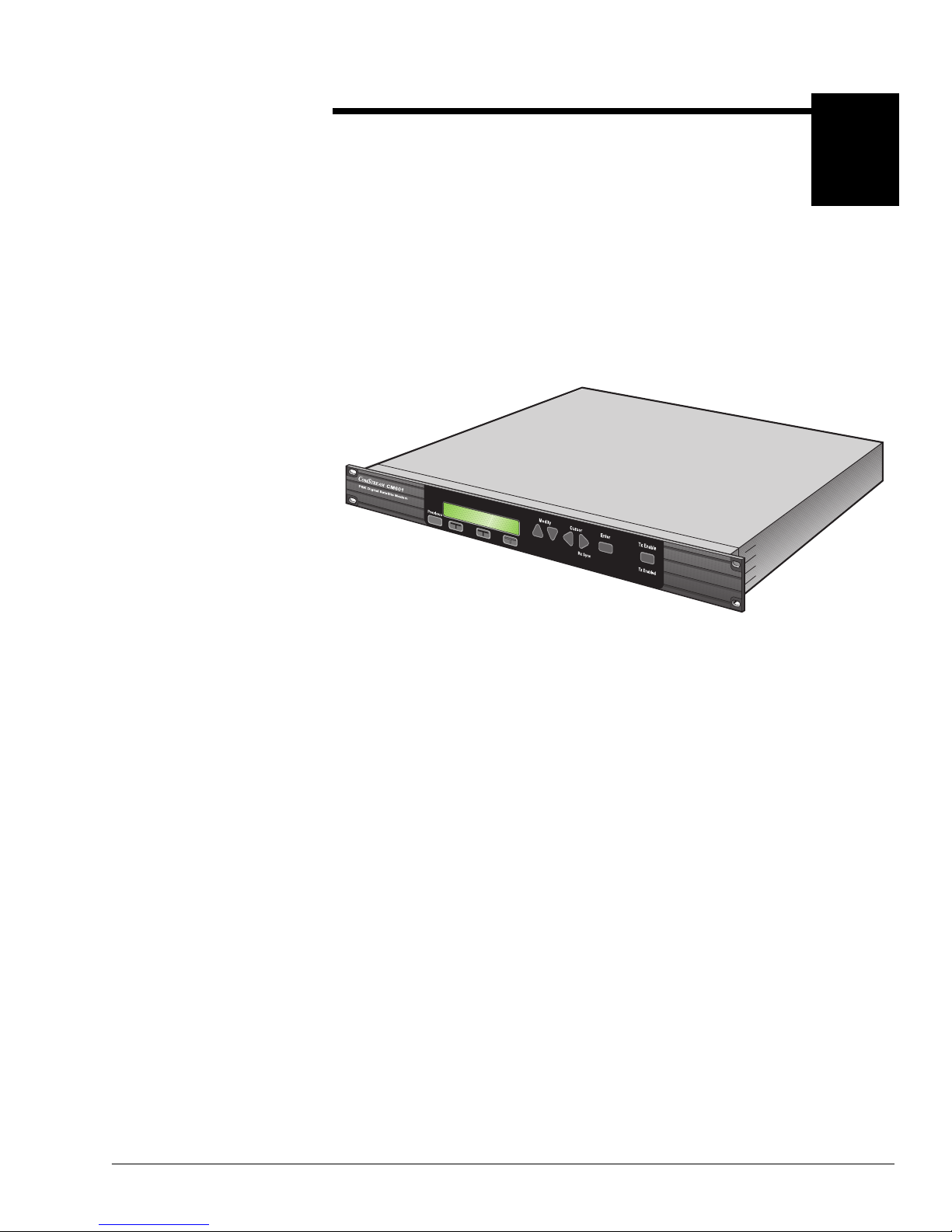
The ComStream CM601 PSK Digital Satellite Modem (CM601), shown in
Figure 1-1, is the low-cost, high-performance, and highly reliable solution for
simple, low- speed data transmissions in closed-networ k environments.
Figure 1-1 CM 601 PSK Digital Satellite Modem
Based on ComStream’s CM701 modular modem technology, the CM601 is a
three-card d es ign that includes a modem card with data int erfac e, a monitor and
control (M&C) card, and one user-specified option card. These are standalone
option cards that work toge ther as a system. These option cards are install ed or
changed by si mply sli ding t hem i n or out of the cha ssis a t t he rear panel, m uch li ke
the circuit cards in a PC. The power supply module and front panel are also
remova ble and replaceable in the field.
This modularity simpli fies sparing as only indi vidual option cards need to be
changed. System changes or upgrade s are much simpler to manage since u nits are
universal; they can be reconfigured to fit the required application.
Individua l monitor and control (M&C) for each CM601 is accessed through
ComStream’s exclusive Wi ndows 95
®
/NT® virtual control panel — an
easy-to-use, graphical user interface program. The modem can also be controlled
through an ASCII terminal, any PC using terminal emulation software, or from
the interacti v e f ront pane l. Ful l networ k remot e M&C is of fe red using the opt ional
ComStream Satellite Cont rol Channel (SCC) card and Star Networ k Management
Software (SNMS).
G732-01
Page 22
1-2 Overview
The CM601 is a complete 4.8 to 512 kbps modem contained in a one-rack-unithigh chassis. The modem car d contains a modula tor , de modulator, Doppler buf fer,
and an RS-449/442 or V.35 interface port. The modem supports variable rates in
1 bps steps. The card offers QPSK and BPSK operations with Vite rbi decoding at
rates of
1
/2
,
3
/4
, and
7
/8
or sequential dec oding rates of
1
/2
and
3
/4
. All programmable
modem features can be modified through the front panel or serial remote control
port.
The CM601 can inter-oper ate with standard, full-featured CM701 modems or
DT7000/8000 earth stati ons. CM701 or DT7000/8000 option cards, such as the
Reed-Solomon codec, satellite control c han nel (SCC), and the CX101/801 line of
redundancy swit ches are fully compatible with the CM601 modem.
Applications The CM601 is particularl y well-suited for
bandwidth on demand
or as a means to
support applicat ions requiring more than one data rate. The CM601 is typically
used in the following applications:
Point-to-point, clear-channel applications that connect computers or support
trunk data traffic
Point-to-multipoint applications that support telephony, facsimile (fax), and
data using voice /data multiplexe rs
Point-to-point applications tha t support trunking telephony voice circuits
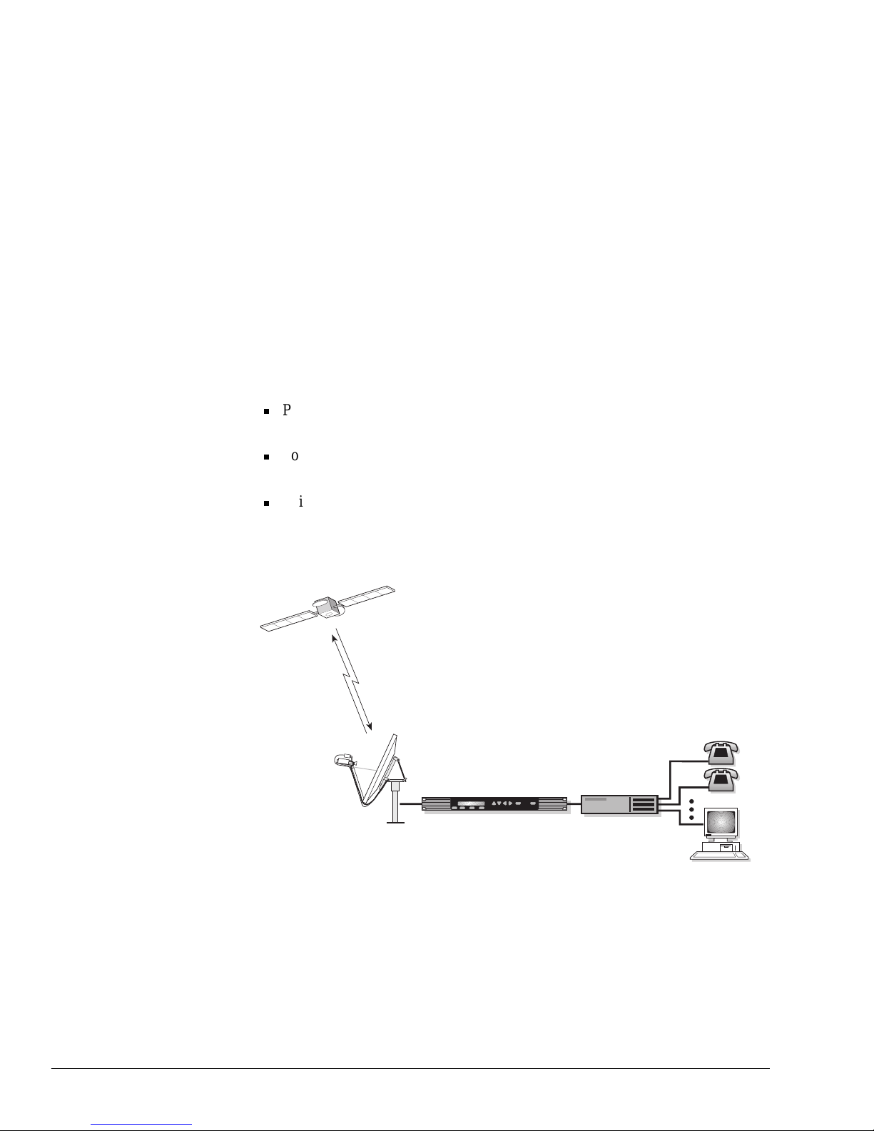
A single carrier per channel (SCPC) application using the ComStream CM601 is
shown in Figure 1-2.
Figure 1-2 SCPC Application Using the CM601
Demultiplexer
CM601
Indoor Unit
Outdoor Unit
Remote Station
#1
#2
Antenna
G630-01
Page 23

Overview 1-3
Features The CM601 provides quality, flexibility, reliability, and value through the
following f eatures:
Ability to communicate with any other ComStream close d-n et work mo d em
including the CV and CM satellite modem product lines on an SCPC basis
The CM2000, CM3000, and CM720 do not communicate with the CM601.
Compatibility with the ComStream DT series of earth stations and the DBR
series of clear -channel, digital broadcast receivers
Use of ComStream application-spe cific, state-of-the-art, integrated digital
circuits (ASICs).
Front panel LED indicators pro vide
at-a-glance
status checking.
Local config uration settings can be issued through the interactive front panel,
a remote terminal, or a computer running Quic kLink™
Every CM601 has an interactive front panel with push buttons, LED
indicators, and an LCD display allowing the CM601 to be completely
configure d, mon itored, and controlled from the front pane l.
A remote terminal is easily connected to a rear panel port allowing the CM601
to be configured, monitored, and controlled with character-or iented ASCII
protocol and RS-232 electrica l le vels . In addition, thr ough the use of a remote
command, the front panel can be disabled to prevent tampering by
unauthorized perso nnel if required.
Applications requi ring the control of many CM601 units on a single remote
control bus can be configured for RS-485 electrical levels and packet-based
protocol to accommodate this operating mode.
There are no internal jum pers, str aps, or switche s requi red for opera tion. And,
since there is no need to disassembl e the unit, configuratio n is simpler with
less chance of damaging circui t car ds or misplacing cables.
Custom configurations can be ordered and shipped from the factory or
configurations can be easily changed on-site through the installation of
CM601 option cards
Flexible operating parameters
User data rates from 4.8 kbps to 512 kbps with 1-bps resol ution
Programmable transmit/receive (Tx/Rx) IF synthesizers with 10-Hz
resolution
Bi-phase shift keying (BPSK) and quadrature phase shift keying ( QPSK)
modulation
Convolutional encoder/Viterbi and sequential decoders
Forward error correction (FEC) code rates 1/2, 3/4, and 7/8 as well as
uncoded operation
ComStre am V. 35 an d ID R sc ram b ler/ d escrambler
Integrat ed monitor and control (M&C) card with remote and local control
Page 24

1-4 Overview
Complete digi tal processing, including IF synthesis and baseband fi ltering
Data interface options for RS-449, V.35, and RS-232
Real-time clock for time-stamped fault reporting
Exceptional bit erro r rat e (BER) versus Eb/N0 performance
Autoranging powe r supply
Automatic configuration capability for virtually any common operating
mode
Extensive built-in diagnostics, including system loopback and self-test
capabilitie s, ai med at dete cting faults in both the interna l circuitry and the
external satellite communications link
Each CM601 card has an integrated microcontroller that performs built-in test
algorithms to verif y proper operation.
An
optional
bit error rate test er (BERT) that allows sat el lite link integrity
testing through the remote te rminal or front panel, which helps reduce satellite
circuit operati ng costs.
Modular Architecture The CM601 was designed using a modular archite cture which provides the
following a dvantages:
Independent functioning of each card
The CM601 can be customized for specific needs today and upgraded or
expanded to meet the planned and unforeseen needs of tomorrow.
Simple, less-costly sparing
Easy, onsite c onfiguration changes
Fast, manageable, onsite repairs
Most repairs can be completed onsite, eliminating shipment of the CM601 to
the factory and avoiding long transit or customs delays. This ensures that, in
the unlikely event of a failure, your netw ork is up and running in minimal
time.
Page 25
Theory of Operation 2-1
2
Theory of Operation
CM601 Architecture
Overview
The CM601 is a 1U tall (1.75 inch), 19-inch rack-mount unit consisting of the
following major components:
Chassis
Power supply
Backplane
Two standard cards and one user-specified option card
Chassis
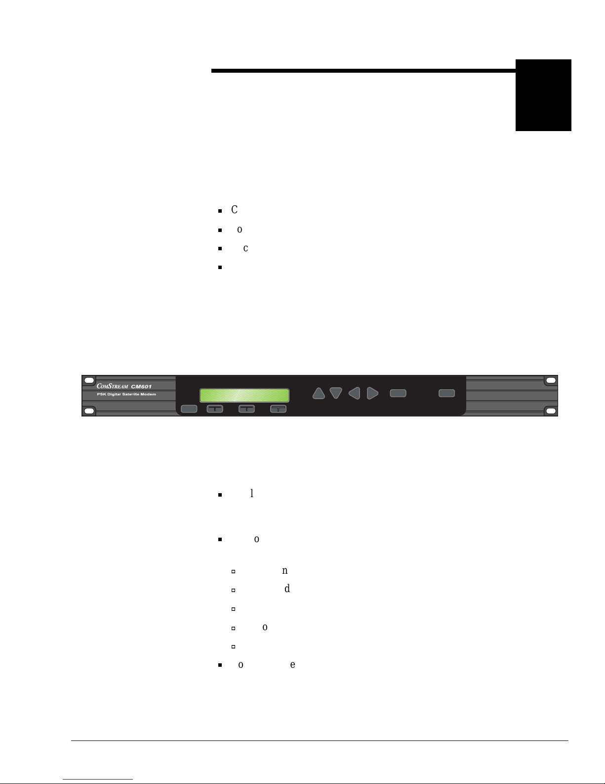
The CM601 chassis is constructed of a steel sheet-metal frame with a nonremova ble top cove r. The front panel, shown in Figure 2-1, allows local control of
the CM601.
Figure 2-1 CM601 Front Panel
The front panel consists of:
A 2-line, 24-character LCD which displays the modem ID on the first line,
and on the sec ond line, commands used to configure , monitor, and control the
CM601, as well as status, fault, and error information
The followin g LED indicators which pro vi de
at-a glance
status and fault alert
information:
View Only
Test Mode
RxSync
Two Fault LEDs
Tx Enable
Command tree push b utton s, loc ated dir ectly belo w the LC D, used to navigate
through and select configuration, monitor, and fault commands
Previous
Modify Cursor Enter Tx Enable
View Only Test Mode Rx Sync FAULT FAULT Tx Enabled
G733-01
Page 26
2-2 Theory of Operation
Selection push buttons, including previous, modify, cursor, and enter, used to
navigat e through commands, select command parameters, and issue
commands to the system
A dedicated TxEnable push b utton with illuminated message
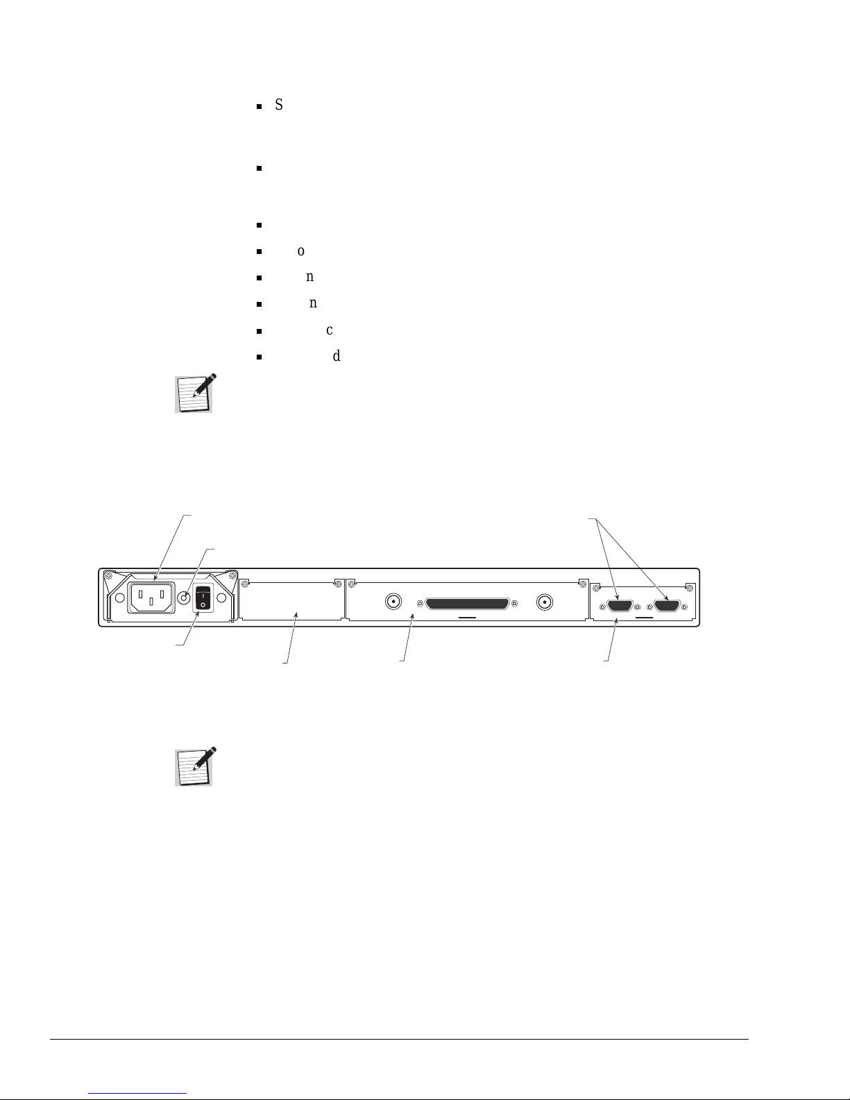
The rear panel, shown in Figure 2-2, houses all external con nections including:
AC power connector whic h inte rface s to th e power supply inside
On/off po wer switch
Ground stud
Option card (in slot 1)
Modem card (in slot 5)
M&C card (in slot 4)
For ease of s et-up and s ystem conf igur ation, the CM601 sl ot numbers ( 1, 5, and 4)
correspond to the slot numbers used in the CM701, DT7000, and DT8000 earth
stations. These slot numbers, or identifiers, are used for reference while cabling a
CM601 or when setting the option card slot configuration.
Figure 2-2 CM 601 Rear Panel
Many of the CM601 cards have LED indicators that are visible through hole s in
the rear panel filler plates and that may be on, off, or blinking. These indicators
are used by ComStream fact ory technicians and should be ignored during normal
CM601 operations.
H097-01
J3: TxIF
J5: RxIF
Low Speed Modem
J1:Remote Control
J2:Status Relay
J4: Tx/Rx Data RS-449
IEC AC
receptacle
Slot 5
Modem card
Slot 1
Option card
Female D
connectors
Slot 4
M&C card
On/Off
Switch
Ground
Stud
Page 27
Theory of Operation 2-3
Pow er Supply
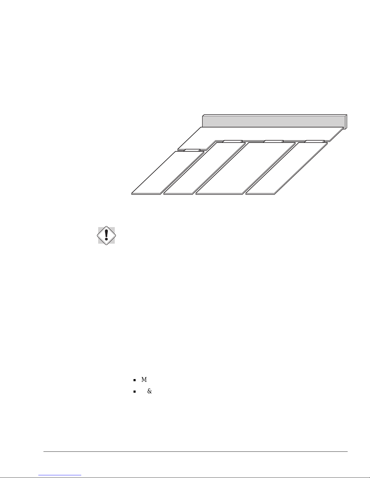
The CM601’ s autoranging AC power supply, shown in the block diagram in
Figure 2-3, accommodates input v oltage s in the range of 90 to 264 VAC and input
frequencies in the range of 47 to 63 Hz. Two AC power cords are provided with
each CM601, one for North American applicat ions and another for all
international applications.
Figure 2-3 CM 601 Mecha nical Block Diagram
AC wiring at the CM601 installation site must be done in accordance with
government stand a rd s and co d es. For det ail ed power sou rce in fo rm at ion, refer t o
the
Safety Prec autions
section.
Backplane
The CM601 backplane, shown in Figure 2-3, provides interconnects for control,
data, clock, frequ en cy referen c e, an d various other handshake signals between
cards. The backplane hardware supports three elementary clock and data transmit
paths and three elementary clock and data receive paths. Each of the transmit and
receiv e paths can be accessed by a card in any of the available slots.
To improv e reliability, the CM601 has no interconnect cables inside the chassis.
Standard Cards
All CM601 cards contain an integr ated microcontroller, NV memory, and unique
control commands for configur ation and status reporting. The two standard
CM601 cards are the:
Modem card, located in slot 5
M&C card, located in slot 4
The CM601 Modem card incorporates the data interface I/O, Doppler buffer,
modulator, demodulator function s. This Mod em card int erfaces with the M&C
card through the ba ckplane . In additi on, a B ERT can be added through an optional
modem card.
M&C Card
Modem Card
Option Card Slot
Power Supply
Backplane
Front Panel
G735-01
Page 28

2-4 Theory of Operation
The CM601 M&C card is the focal point for all user interface command and
control activities. This card serves as a command gateway between you, the
operator, and any other CM601 cards. It supports status relay output as well as
status relay sense sig nal inputs. The remote control port and front panel user
interface s are suppo rted by the M&C microcontroller.
Option Cards
The CM601 can accommodate one user-specified option card in addition to the
two required cards. The most common option cards are:
Satellite Contro l Channe l
ComStream Reed-Solomon
Satellite Contro l Channe l/ComStream Reed-Solomon combination card
For additional info rmation on and availa bility of these option cards, call
ComStream Customer Service.
If an option card or different data interface card is required, it is installed in slot 1.
If this slot is not used, it must be covered by a blank filler plate to suppress
emissions and ensure safety-regulation compli ance.
It is possible for two of the same type of option cards to operate in the CM601 at
the same time. This common application is required when the interface on the
transmit side is different than that on the receive side. For exa mple, the required
transmit data rate may be 512 kbps with an RS-449 electri cal interface. However,
the required recei v e data rate may be 9.6 kbps with an RS-232 electrical interface.
The CM601 easily supports this applic a tion requirement by allo wing both an
RS-449 modem card and an RS-232 data I/O card to be installed. You, the
operator, then designate the transmit and receive I/O parameters by issuing
commands through either the front panel or remote terminal
Additional CM601 option cards can be ordered to simplify sparing or to allow
configura tion changes without returning a CM601 to the factory . All CM601
option cards describ ed in this guide can be ordered individual ly.
System Monitor and Control
The CM601 modem and its cards can be configured, monitored, and controlled
from either the front panel or remote term inal.
Local CM601 control is provided through the front panel push buttons, LCD
display, and LED indicators.
Remote CM601 control is provide d through the remote terminal, which is
connected to the CM601 at the M&C remote control port. The remote te rminal is
used to issue commands and monitor status typically using ASCII protocol and
RS-232 electrical levels. This remote interface can also be configured for RS-485
electrical levels and packet-based protocol when required.
Page 29
Theory of Operation 2-5
Modem Card The CM601 is typically configured for full-duplex ope ration, transmittin g and
receiv ing data from the satellite. These two paths are independent for most
applications. The modem card incorporates the modulator, demodulator, data I/O
interface , and Doppler buffer functions.
Modulator
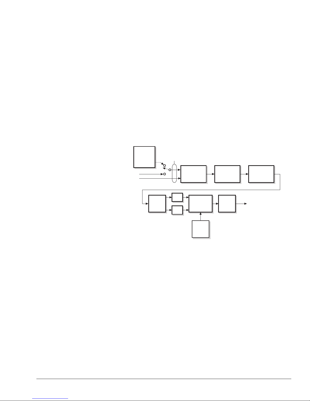
In the transmit process, illustrated in Figure 2-4, the CM601:
1. Accepts user data at the data inte rface card (modem or I/O option card)
2. Directs the tr ansmit or send data ( SD) across the backplane, clocking the data
by either Station Timing (ST) or Tr ansmit Timing (TT), depending upon the
clocking configuration of the unit
3. Directs the data through any optional, transmit-data-processing card (for
example, the Satellite Control Channel card)
Figure 2-4 CM 601 Transmit Process
4. Provides the data to the modulat or (modem card) for processing; the data
processing consis ts of:
a. Scrambling (ComStream version V.35 or IDR)
b. Differential encoding
c. Convolut iona l encoding for er ror-correction decoding. The modulator can
encode the data with convolutional cod es that are Vi terbi rate 1/2, 3/4, or
7/8 compatible, as well as IESS-312 compatible Sequential rate 1/2 and
ComStream Sequential rate 3/4.
5. Passes the processed data through a digital matched f ilter
6. Con verts the data from digital to analog (D/A) signal
7. Uses the signal to PSK-modulate an IF carrier . Once the signal reaches the
intermediate fre quency, the modulated carrier is available for transmission. In
this illustrat ion, the QPSK modulator is used.
G329-01
Digital
Clock
Synthe-
sizer
Scrambler
Convolutional
Encoder
Differential
Encoder
TT
SD
From
data
interface
module
ST
Digital
Filter
D/A
D/A
QPSK
Modulator
IF
Synthe-
sizer
Power
Control
Backplane
(optional)
TxIF
Page 30
2-6 Theory of Operation
8. Passes the carrier signal through power-control circ uitry and out the rear of
the CM601
The proprietary digi tal-match filter design allows tremendous fle xibility under
software control to create virtually any PSK waveform necessary to comply with
open-network specifications or to optimize channel performance.
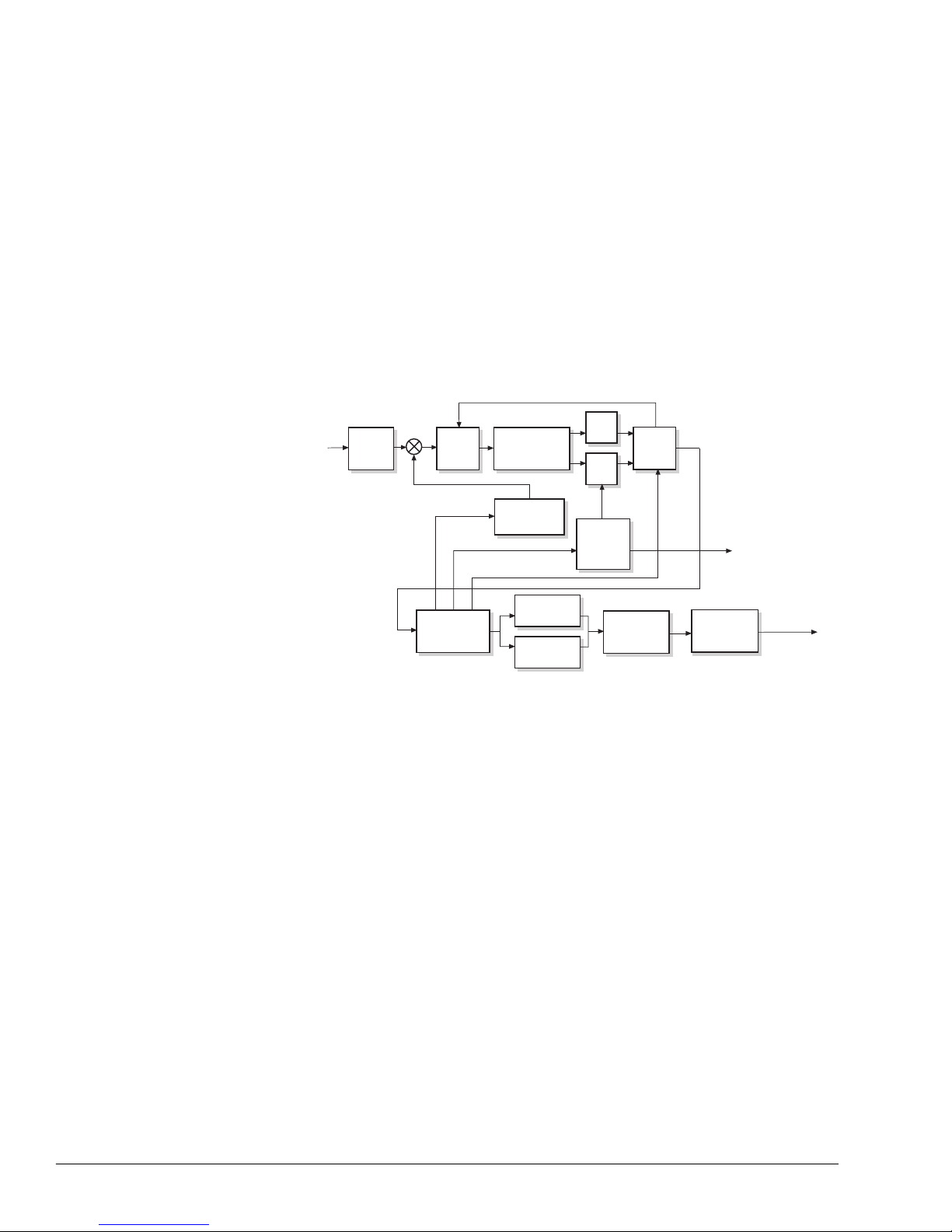
Demodulator
In the receive process, shown in Figure 2-5, the following occurs:
1. The IF Rx input signal is input at the BNC connector on the modem card,
labeled RxIF.
Figure 2-5 L-B and Dem odulator Block Diagram
2. The IF carrier is removed by a QPSK demodulator.
3. The input passe s through an AGC amplifier. The AGC amplifi er se ction has a
wide dynamic range and is controll ed to kee p its output signal at an optimal
level, regardless of the input signal level.
4. The resulting analog baseband signals are digitized. After the signals are
digitized, all remaining signal processing is digi tal .
5. The first digita l block encountered after the analog-to-digital converters is a
digital bas eband filter. This patented filter ASIC is software-programmable to
realize a vari ety of equalized f ilte r shapes at data rates from belo w 9.6 kbps to
above 512 kbps.
6. The filte red samples are passed to the digital demodulator processor ASIC.
This processor close s the tracking loops for the IF carrier, symbol time clock,
and AGC amplifier (through the filter ASIC), all under digital control. The
carrier and clo ck frequenc y tracki ng loops a re digita ll y controlle d using dir ect
digital synthesi zer (DDS) ASICs in the IF synthesizer and digital clock
synthesizer blocks.
RxIF
IF
Filter
AGC
Nyquist
Filter
A/D
A/D
Digital
Filter
IF
Synthesizer
Digital
Clock
Synthe-
sizer
Demodulator
Processor
Sequential
Decoder
Viterbi
Decoder
Differential
Decoder
Descrambler
RD
To data
interface
module or
other option
module
RT
G330-01
Page 31
Theory of Operation 2-7
7. The demodulator function mixes the IF carrier do wn to baseband. The
demodulated channel symbols are then:
a. Decoded by a Vi terbi or Sequential decoder depend ing on the ins talled
modem card an d the o rd ere d options.
b. Differentially decoded
c. Descrambled
8. The data is directed across the backplane through any optional, receive dataprocessing card (for e xample, the SCC card).
9. The data is directed back to the modem card where it is converted to the
appropriate electrical levels and then passed to the user.
10. The rec eive clock and data are provided by the demodulator card to the data
interface card across the CM601 backplane.
Data I/O Interface
The modem card provides aV.35 or RS-449 data path for data sent to and from the
modem. Other interface types are ava ilable using the option card slot.
Doppler Buffer
ComStream’ s Doppl er B uf fer is a f eature tha t i s standar d on ev ery CM601 m odem
card. It buffers data received from the satellite on a f irst-in-fir st-out (FIFO) basis.
Data is input to the buffer using the receive clock from the satell ite signal. The
Doppler bu ffer is of programmable depth to ensure that the receive clock and da ta
from the satellite are sync hronized or are set to another clock as necessary.
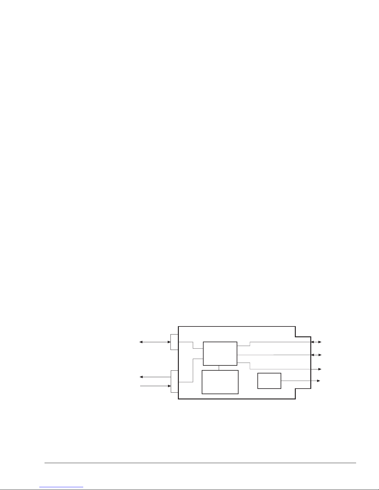
M&C Card The M&C card, illustrated in Figure 2-6, performs traffic management and relays
messages between the front panel or remote control interface and the target
CM601 card. In this bus-oriented control configuration, the M&C card is called
the
master
, and all other cards are called
slaves
.
Figure 2-6 M&C Card
G328-01
RS-232 or
RS-485
remote control
Status relay
Relay sense lines
Front panel
interface
Backplane
control bus
System reset
20-MHz
reference
20-MHz
TCXO
Master
Microcontroller
Battery-Backed
RAM and Real-
Time Clock
Page 32

2-8 Theory of Operation
CM601 control commands are entered thro ugh the front panel or remote te rminal.
These commands are exec uted by the M&C card by passing addressed message
packets along the multidrop bus to a particular slave card. The slave responds and
then the M&C card displays a response on the front panel LCD or remote
terminal.
In addition to command processing and user-interface management, the M&C
card maintains the CM601 system configuration in a battery-ba cked RAM. A
real-time cloc k all o ws f ault e v ents t o be time- tagged and st ored in NV m emory f or
viewing at a later date.
A 20-MHz tempera ture compensated cr ystal oscillator (TCXO) provides a singlefrequency reference to the entire CM601 chassis and all cards within it. A high
stability oven-controlled crystal oscillator (OCXO) is available as an option. The
benefits of this single-frequency reference are as follows:
Reduces cost
Reduces frequency sour ce interactions within the chassis
Allows complete ly synchronous digital-dat a-path processing within a single
card as well as within data paths across the backplane
The system reset signal is controlled by the master microcontroller and the
internal backpla ne control bus that connects to each card in the chas sis.
BERT The ComStream CM601 internal BERT, an
optional featu re
on the CM601
modem, is an easy-to-use yet highly sophisticated testing feature. The BERT is
used to verify sate llite link performance and earth stati on/RF equipment
operation, and to tr oubleshoo t basic satell ite link a nd equipm ent proble ms witho ut
external test e quipment.
Page 33
External Connections 3-1
3
External Connections
A description of the standar d CM601 ext ernal connections is presented in this
chapter. The following information is provided for each of the CM601
components:
Functional descri ption
Electrical specification
Physical pinout specification
The CM601’ s modular architecture allows for many different connector
configura tions, depending upon the option cards installed. For informat ion on
external conne ctions for option cards, includ ing other data interface cards, refer to
the specifi c user guide that accompanies each option card.
Low-Speed Modem
Card Connectors
The three connectors listed in Table 3-1 are found on the CM601 Low-Speed
modem card.
Tx/Rx Connector
The Tx/Rx data connectors provide the data, clock, and data control signal s
between the CM601 and the user data equipment. These interfaces are designed
for cable distances up to 61 m (approximately 200 ft.).
The standard CM601 is conf igur ed with e ither an RS-449 or V.35 interface, which
is built-into the board.
Table 3-1 Modem Card Connectors
Connector Name (Type)
RS-449
Connector
Number
V.35
Connector
Number
Function
Tx/Rx Data (25- or 37-pin
D, female)
J4 J7 RS-449 or V.35 data interface
between the CM601 and the
data terminal equipment
Tx IF (BNC) J3 J6 Transmits IF signal
Rx IF (BNC) J5 J8 Receives IF input
Page 34

3-2 External Connections
EIA RS-449 Electrical Specifications
The EIA RS-449 electrical specifications are shown in Table 3-2 for dif f erential
(RS-422) and single-ende d (RS-423) drivers a nd receivers.
The differe ntial pair has a true signal, indicated by a B, and an inverted signal,
indicated by an A. These two differential signa ls must always be opposite in
polarity. With no line attenuation, each signal should be within ±1.5 V of the
nominal level, which is approximately 2.5 V above signal ground. Driver and
receiver impedanc e are i ncl ude d for ref ere nc e only.
The CM601 data connector is pinned out as data communications equipment
(DCE); therefore, the user data equipment must be configured as data terminal
equipment (DTE) in order to make a straight cable between them.
Table 3-2 Electr ical Specifications for Differential (RS-442) and Single-Ended
(RS-423) Drivers and Receivers
Driver Specifications
Differenti al Driver
(Output)
B – true signal, 0 or 5 V
A – inverted signal, 5 or 0 V
Less than 100 ohms between A and B
Single-Ended Driver
(Output)
Greater than +3 V or less than -3 V with respect to signal ground
Less than 50 ohms with respect to signal ground
Differenti al Recei ver
(Input)
B – true signal, 0 or 5 V
A – inverted signal, 5 or 0 V
100 ohms between A and B
Single-Ended Receiver
(Input)
Greater than +3 V or less than -3 V with respect to signal ground
Minimum 4 kohms signal to ground
Page 35

External Connections 3-3
The Tx/Rx mechanical pinout for the RS-449 data interface is pr es ent ed in
Table 3-3.
Table 3-3 RS-449 Data Interface 37-Pin Connector Pinout
Pin Description Signal Direction
1 Shield — Ground
2 No connection N/C Open
3 Reserved
1
Reserved —
4 Send data SD-A Input
5 Station timing ST-A O utput
6 Receive data RD-A Output
7 Request to send RS-A Input
8 Receive timing RT-A Output
9 Clear to send CS-A Out put
10 No connection N/C Open
11 Data mode DM-A Output
12 T e rminal ready TR-A Input
13 Receiver ready RR-A Output
14 No connection N/C Open
15 No connection N/C Open
16 No connection N/C Open
17 T r ansmit timing TT-A Input
18 Reserved
1
Reserved —
19 Signal ground SG Ground
20 Common — Ground
21 Reserved
1
Reserved —
22 Send data SD-B Input
23 Station timing ST-B O ut put
24 Receive data RD-B Output
25 Request to send RS-B Input
26 Receive timing RT-B Output
27 Clear to send CS-B Output
28 No connection N/C Open
29 Data mode DM-B Output
30 T e rminal ready TR-B Input
31 Receiver ready RR-B Output
32 No connection N/C Open
33 Signal quality SQ Output
34 No connection N/C Open
35 T r ansmit timing TT-B Input
36 No connection N/C Open
37 Send commo n SC Ground
1
Do not connect reserved lines.
A and B denote twisted, differential pairs.
For a binary one, the B signal is positive with respect to the A signal.
Page 36

3-4 External Connections
The Tx/Rx mechanical pinout for the V.35 data interface is presented in Table 3-4.
Table 3-4
V.35 Interface Connector Pinout
Pin Description Signal Direction
1 Shield — Ground
2 Send data B SD-B Input
3 Receive data B RD-B Output
4 Request to send RTS Input
5 Clear to send CTS Output
6 Data set ready D S R Output
7 Signal ground SG Ground
8 Receiver ready RR Output
9 No connection N/C Open
10 Send timing ST-A Output
11 Receive timing RT-A Output
12 Transmit timing TT-A Input
13 Reserved
1
Reserved —
14 Send data SD-A Input
15 Receive data RD-A Output
16 No connection N/C Open
17 No connection N/C Open
18 No connection N/C Open
19 Reserved
1
Reserved —
20 Data terminal ready D TR Input
21 Reserved
1
Reserved —
22 Send timing ST-B Output
23 Receive timing RT-B Output
24 Transmit timing TT-B Input
25 No connection N/C Open
1
Do not connect reserved lines.
A and B denote twisted, differential pairs.
For a binary one, the B signal is positive with respect to the A signal.
Page 37
External Connections 3-5
Signal Descriptions
There are two types of data path signals, transmit and receive. The signals
associated with the transmit path are described in Table 3-5. The signals
associated with the receive path are described in Table 3-6.
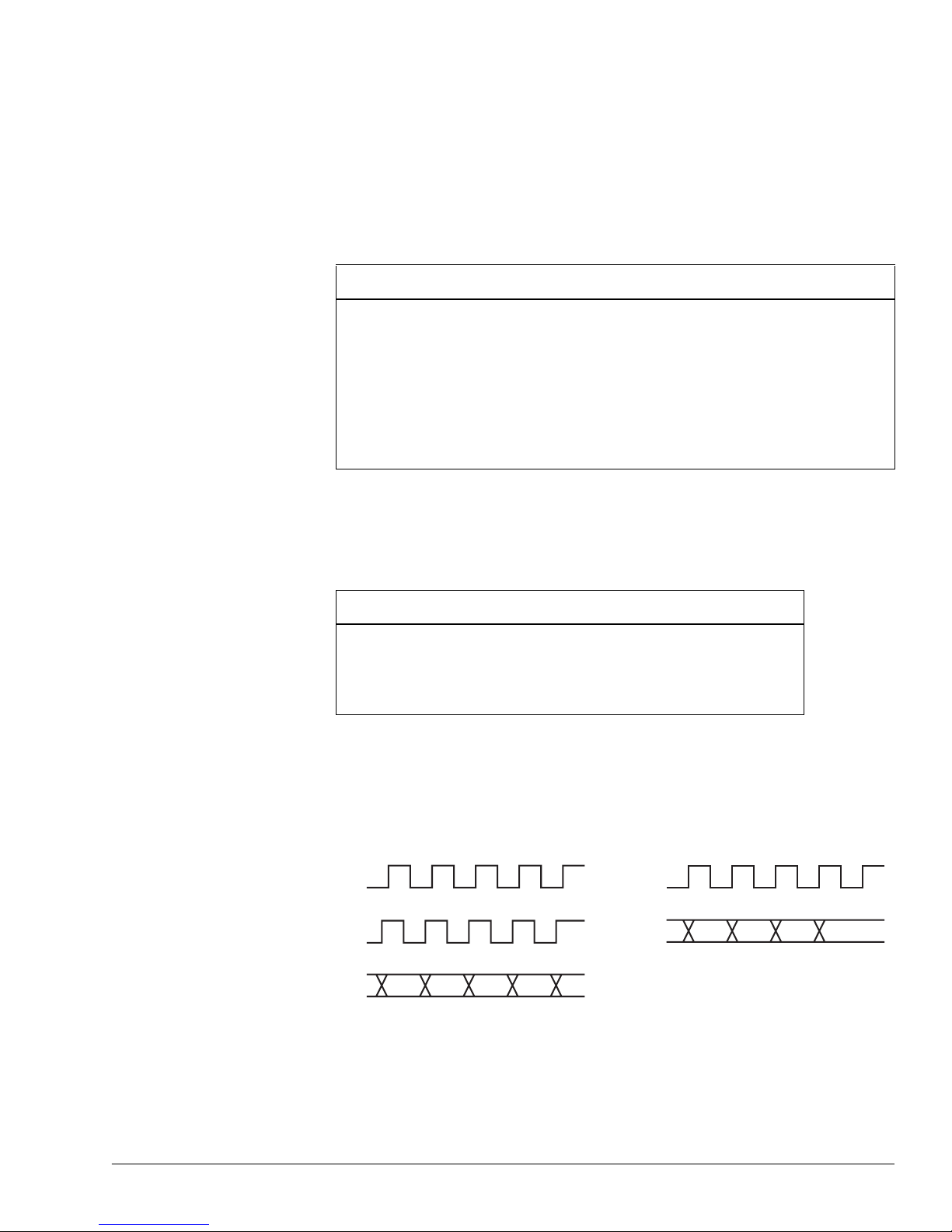
Clock/Data Relationships for the RS-449 and V.35 Interface Cards
For differential signal pairs that carry clock signals, corresponding data signals
falling edge of the cloc k signa l. F igure 3-1 illustrates RS-449 and V.35 timing.
Figure 3-1 Clock and Data Signal Timing Diagram
Table 3-5 Transmit Path Signals
Transmit Path Signal Description
Station Timing (ST) A transmit clock generated by the CM601 when configured for Internal
timing. This clock is accurate to better than 4 ppm.
Transmit Timing (TT) The transmit clock provided to the CM601 by the DTE. Typically, the
CM601 is configured for External timing when TT is supplied.
Send Data (SD) The transmit data provided to the CM601 by the DTE. This data should
transition on the rising edge of TT or ST, depending on which clock is
being used, and be stable on the falli ng edge. The clock rate of TT and
ST equal the transmit data rate of the CM601.
Table 3-6 Receive Path Signals
Receive Path Signal Description
Receive Timing (RT) The receive clock that is extract ed from the receive
signal by the demodulator.
Receive Data (RD) The demodulated data that is synchronous with and
transitions on the rising edge of RT.
G480-01
ST-B
TT-B
SD-B
RT-B
RD-B
Page 38

3-6 External Connections
The followin g should be noted regarding signal timing:
The ST clock from the modem has no definite phase relationship to the TT
clock or SD. In circuits with high data rate s, greater than 512 kbps, or long
cable runs, greater than 3 m (10 ft), it is critical that the modem latch data on
the TT clock. This can be accomplished b y using the ML 0 command.
SD must always transit ion co incident with the low-to- high transition of the
TT-B clock. SD is latc hed into the modem on the high-to-low transiti on of the
TT-B clock.
RD from the modem always transiti ons on the low-to-high transition of the
RT-B clock. RD should be latched by DTE equipment on the high-to-low
transition of RT-B.
RS-449 Data Control Signals
For differential signal pairs that carry data control signals, an On condition is
indicated by a positive state on the A signal, and an Off condition is indicated by a
positi ve state on the B signal.
V.35 Data Control Signals
V.35 data control signals a re si ngle ended RS-232 level signals following standard
RS-232 con ventions.
Applications Not Requiring Data Control Signaling
For most CM601 applicatio ns, da ta control signaling is not required. F or these
applications, data control is disabled by issuing CD 1, which sets:
Output data control signals (CS and DM) permanently to the On state
Input data control signals ( RS and TR) to ignore
Applications Requiring Data Control Signaling
For applications requiring the use of data control signaling, a CD 2 command is
issued, which enables the CM601 to exchange data control signals with the DTE.
With a CD 2 command issued:
TR signal should be set to On when the DTE is powered on
DM signal will be On indicating that the CM601 is powered up and TR is On
With data control enabled (CD 2), the DTE must:
Initiate data transmission by setting the Request-to-Send (RS) signal to On
Wait for the CM60 1 to set the Clear-t o-Send (CS) signal to On; the CS signal
indicates that the CM601 is ready to accept the data that the DTE ne eds to
transmit
When data control is e nabled, RD is clamped when RR is not set to On to prevent
invalid data from being passed to the DTE by the CM601.
Page 39

External Connections 3-7
The CM601 will always set the RR signal to On when the entire receive path is
locked to the receive signal and RD represents valid data. This will occur whether
the CM601 data control mode is set to Off or On (CD 1 or 2).
When the modem is set for data control mode using the CD 2 command, the data
control signals RS, TR, DM, CS, and RR are defined, a s shown in Table 3-7.
Signal Quality
Signal quality is supported only by the RS-449 interface. The signal is active
when the CM601 E
b/N0
falls below the user-specified threshold, which is set with
the EBT command. Signal quality can be used to sound an alarm or log a fault
condition when data integrity falls below the specified thr esh old.
Tx IF Connector
The Tx IF connector provides the transmit IF output to the RF equipment. The
CM601 modulator has electroni cally adjustable output power. The output power
adjustments can be made using the front panel Tx Pwr Level command or the
remote TP command.
For normal CM601 operation, the output power of the m odulator is set between 5 to -25 dBm in 0.1-dB step s. The output frequency is programmable in the range
of 52 to 88MHz or 104 to 176MHz depending on the modem card options
ordered. The output impedance is 75 ohms with a return loss of 20 dB or better.
Rx IF Connector
The Rx IF connector is used to rec ei v e the IF signal. The po wer of the in put signal
must be in the range of -10 to -55 dBm. The IF frequency must be in the range of
52 to 88MHz or 104 to 176MHz depending on the modem card options ordered.
Table 3-7 Data Control Signals
Data Control Signal Descript ion
RS and TR Setting both signals to On will allow the modem to transmit. It is
recommended that RS be used as the primary transmit control line.
Setting either line to Off will disable transmission. The modem is
powered on and the DTE TR is set to On.
DM DM is set to On by the modem when data control mode is selected.
CS CS is set to On by the modem when the modulator is ready to accept
data.
RR RR is set to On by the modem when the demodulator has acquired and
is receiving val id data.
Page 40

3-8 External Connections
M&C Card The M&C card has two D connectors which are described in Ta ble 3-8.
Remote Control Connector
This connector provides the RS-232 or RS-485 signals that connect the CM601 to
the remote terminal. Communicatio n betwe en the CM601 a nd th e remote termina l
is asynchronous serial.
Signals from the electri cal interface driver and receiver connections on the M&C
card are routed through relay contacts. These relay contacts enable one 9-pin
connector to support both an RS-232 and RS-485 interface, even though the two
interfaces must share the same pins for different signals.
The remote interface can be configured fo r RS- 2 32 or RS-485 electrica l levels
remotely. For details on selecting various remote configuration pa rameters, refer
to the BR, MDP, MEI, MPT, and MPA commands.
RS-232 Applications
A 9-to-25-pin cable is included in every CM601 shipping kit for use with RS-232
applications. This cable is used to convert the 9-pin remote interface connector to
a 25-pin RS-232 connec tor, which is commonly found on standard, asynchronous
computer terminals.
The RS-232E electrical interface defines a single-ended signal with valid levels
from +3 to +6 V and from -3 to -6 V, with respect to signal ground.
Because the CM601 is defined as a DCE device, the remote terminal must be
configure d as a DTE device.
While the CM601 is powered up, the carrier detect, data set ready, and clear-tosend RS-232 signals are alwa ys active. The request-to-send RS-232 signal is not
currently used by the M&C card.
Table 3-8 M&C Card Connectors
Name Type Number Purpose
Remote Control 9-pin, D, female J1 RS-232 or RS-485 remote
control communications
Status Relay 9-pin, D, female J2 Form-C status relay contacts
and relay sense pins
Page 41

External Connections 3-9
Table 3-9 contains the 9-pin, RS-232, remote connector pinout spec ifications.
Table 3-10 contains the 9-to-25-pin adapter cable pinout specifications.
Table 3-9 RS-232 Remo te 9-Pin Connector
Pinout for DCE
Pin Signal Name Direction
1 Carrier Detect Output
2 Receive Data Output
3 Transmit Data Input
4 Not connected Open
5 Signal Ground Ground
6 Data Set Ready Output
7 Request-to-Send Input
8 Clear-to-Send Output
9 Not connected Open
Table 3-10 RS-232 Remote 9-to-25-Pin
Adapter Cable for DCE
Male D
9-pin
Fem a le D
25-pin
Signal Name
25-pin
1 8 C a rrier Detect
2 3 Rec ei ve Da t a
3 2 Transmit Data
4 20 Not connected
5 7 Signal Ground
6 6 Data Set Ready
7 4 Request-to-Send
8 5 Clear-to-Send
9 22 Not connected
— 1, 9-25 Not connected
Page 42
3-10 External Connections
RS-485 Applications
For RS-485 applications, the remote terminal is connected directly to the remote
control connector. Since the CM601 is defined a s a DCE device, the control unit
must be configured as a DTE device. The RS-485 spe cification defines a
differ ential pair of signals that transitions from 0 to 5 V each. The 9-pin, RS-485
remote control connector pinout is shown in Table 3-11.
Status Relay Connector
The Status Relay connector on the M&C card provides:
Three connections to a F orm-C relay for ind icating CM601 curr ent faul t status
Three pairs of relay sense pins that can be connected to the status relays of
any other equipment . Sense signa ls can be monitored from the front panel or
remote terminal.
The status relay connect or pino ut is provided in Table 3-12.
Table 3-11 RS-485 Remote Connector Pinout for DCE
Pin Signal Name Direction*
1 Signal Ground Ground
3 Transmit + Input
5 Receive + Output
7 Transmit – Input
9 Receive – Output
2, 4, 6, 8 Not connected Open
* For master-slave RS-485 bus connections, this pinout represents a slave when a
straight cable is used to connect the devices on the bus. Note the signal directions, with
transmit being an input and receive an output.
Table 3-12 Status Relay 9-Pin Connector Pinout
Pin Signal Name Description
1 Status Relay B Form-C nor mally open contact
2 Status Relay C Form-C Common contact
3 Relay Sense Pin 3 Relay sense signal
4 Relay Sense Pin 4 Relay sense signal
5 Relay Sense Pin 5 Relay sense signal
6 Status Relay A Form-C normally closed contact
7 Ground Rel ay sense signal return
8 Ground Rel ay sense signal return
9 Ground Rel ay sense signal return
Page 43
External Connections 3-11
Form- C Current Fault Stat us Relay
The Form-C current fault status relay is a real-time indicator for current fault
conditions. The Form-C relay has three passiv e relay contacts:
C – common con tact
B – normally closed contact
A – normally open contact
Under a no-fault condition, C is connected to A and not to B. However, when the
status relay is indica ting a fault condition, C is connected to B and not to A.
The Form-C relay allo ws you to have both normally open (C- A) and normal ly
closed (C-B) contact pair s availabl e to monitor. For example, the Form-C relay
indicates a faul t condi tion when power is off. This condition is indicated by
contact between C and B with no contact between C and A.
The maximum power that can be passed thr ough the relay contacts is 1 VA.
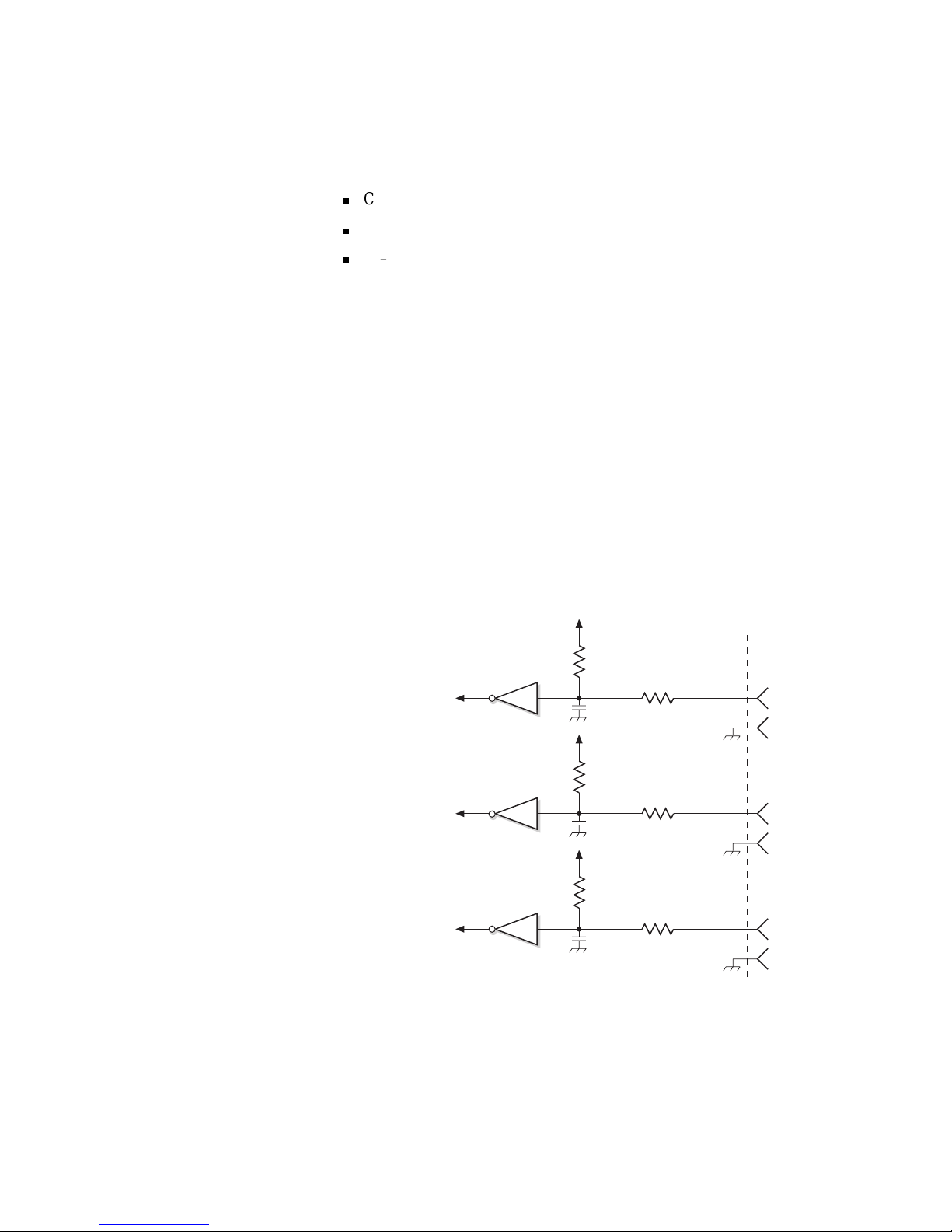
Relay Sense Pins
The status relay on the M&C card has three relay sense signal pins, as shown in
Figure 3-2. Each relay sense pin is paired with a ground pin that is connected
directly to the chassi s ground.
Figure 3-2 Relay Sense Pins
Each pair of relay sense pins can be used to monitor and report the fault status of
other equipment. This configuration allows the M&C card to determine whether
the status relay contac ts from the other equipment are opened or closed.
G363-01
+5 V
10 kohm
27 ohm
Pin 3
+5 V
10 kohm
27 ohm
Pin 4
10 kohm
27 ohm
Pin 5
Microcontroller
0.1 µF
Pin 7
Pin 8
0.1 µF
+5 V
Pin 9
0.1 µF
Page 44

3-12 External Connections
Each relay sense pin is also monitor ed b y the M&C microcontroller , a nd its sta te
is mapped to the current fault status and fault log registers, as shown in
Table 3-13.
Under normal operating conditions, some equipment status relays are open while
others are closed. The Fault Relay Sense External Signal Polarit y (FRX)
command is used to define the fault polarity of the relay sense pins as open or
closed relay contact to ensure accurate monitoring of those conditions.
Table 3-13 Fault Status Bits for Relay Sense Pins
Bit Weight Fault
19 262144 Relay Monitor, Pin 3
20 524288 Relay Monitor, Pin 4
24 8388608 R elay Monitor, Pin 5
Page 45

Installation 4-1
4
Installation
This chapter provides step-by-step instructions for installing the CM601 in a
communications circuit. The installation procedure begins at the preparation
stage, which includes reviewing syste m issues and determining operating
parameters, and ends with a ve rified data communications link and an operational
CM601.
Trouble shooting tips are included to assist you in solving errors commonly
encountered during a CM601 installation.
A shorter , l ess-detail ed versi on of the CM601 i nstall ation pr ocedur e is av a ilab le a s
a separate quick reference card that accompanies this guide. This quick reference
is for those:
Familiar with satellite c ommunications
Experienced with ComStream products and the CM601
Installation Process The following steps provide a high-leve l outline of the installation process.
Detailed instructions for each step are presented in this chapte r.
1. Prepare for CM601 installation.
2. Inspect the CM601 system.
3. Familiar ize yourself with the CM601.
4. Perform a bench-top test.
5. Install and connect the CM601 in a permanent location.
6. Configur e the CM601.
7. Validate the system.
8. Optional Front Pa nel Lockout
For detail ed install ation pr oce dures and i nforma tion on othe r opti on cards, refer to
the specifi c user guide that accompanies each option card.
Page 46

4-2 Installation
Step 1:
Prepare for CM601
Installation
Before installing the CM601, perform the follow ing:
1. Identify any system issues that might impact this installation.
2. Determine the required operating parameters.
System issues and operatin g parame ters are often identified and defined in a
satellite communications system link budget and overall system design. You may
want to determine if one was conducted and, if so:
What issues were identified and resolved?
Which param et ers were d efined ?
If a link budget and overall system design were not conducte d, they should be
completed prior to this ins tal lation.
Identify System Issue s
It is important to identify and resolve system issues before installing the CM601
to ensure efficient and cost-effective installation and system operation. The variety
of system issues that may impact this system configuration and that should be
considered include:
Acquisition performance
Error correction coding
Modulation types
Modem perfo rm an c e
Data throughput requirements
Link availability requirements
Outdoor dish antenna size
Radio and frequency converter gains
System M&C mechanism
For a detailed re view of these and other iss ues that will affect CM601 installation
and configuration, as well as system performance, refe r to the chapte r on
configura tion examples in this guide and to the CM601 Reference Guide .
Site and Equipment Information
Each section of the installation data shee t contains the following helpful
information:
General – this section provides helpful information suc h as site loc ation, site
point of contact (P.O.C.) and phone numbers, and satellite name and
longitude.
Operating parameter s – this section provides a list of the frequenc y and
system performance paramete rs necessary to set up the system.
A known downl ink signal on the desired satellite will a ssist you in the
antenna-pointi ng and peaking process.
Page 47
Installation 4-3
The uplink and downli nk fre quencies are the operational freque nc ies that
must be used, and they must be preauthor ized by the space-segment
vendor or satellite operator.
The initial transmit power is the level authorized for satellite loopbacks
and end-to-end testi ng and may be dif ferent from the final power setting
leve l.
The minimum required Eb/N0 at the remote station reflects the minimum
value for acceptable system performance as calculated by the syste m link
budget. This value must be met during commissioning, or the installation
cannot be regarde d as successful. The final Eb/N0 value should be
recorded and used as a baseline in determining system performance.
Other information include s the various modem operati ng parameters that
determine uplink power.
Configurat ion parameters – this section details the modem configuration for a
specific site. These parameters must be known and set to their proper values
before the bench-top test is pe rfor med.
Installa ti on D ata Sheet
Before beginni ng the phy sical setup and installation of the earth station
components, fill out the following ques tionnaire. It will save time and provide
ease of installati on by identifying decisions about configuration that should be
made beforehand.
Installation Data Sheet
General Information
Date ___________________________Installer _________________________________________________________
Site location ________________________________________________________________________________
Customer
Name _________________________________________ P.O.C. and phone # _________________________________
Satellite
Name _________________________________________Longitude (degrees) ________________________________
Operating Parameters
Transmit frequency (TxIF) ________________ kHz
Tx power (TP) ________________ dBm
Receive frequency (RxIF) ________________ kHz
Min. required Eb/N0 (EB) ____________ dB
Final Eb/N0 (EB) ________________ dB
Configuration Parameters Transmit Receive
Data rate (bps) PTD =_______ PRD =_______
Modulation type (BPSK/QPSK) TM =_______ (0,1) RM =_______ (0,1)
FEC type (off, S 1/2, S 3/4, V 1/2, V 3/4, V 7/8) TC =______ (0,1,2,3,4,5) RC =_______ (0,1,2, 3,4,5)
Differential encoding (off, standard) DM =_______ (0,1) DD =_ ______ (0,1)
Scrambling (off, ComStream, IDR) SM =_______ (0,1,2) SD =_______ (0,1,2)
Acquisition offset (Hz) AO =_______
Acquisition range (Hz) AR =_______
Modulator bit timing (external, internal, loop) MB =_______ (1,2,3)
Modulator latching clock (TT, ST) ML =_______ (0,1)
Page 48

4-4 Installation
Establish Configuration Parameters
Operating parameters must be defined prior to the CM601 installation in order to
configure it correctly and to verify that the unit performs in accordance with
system design specif ications. The follo wing parameters need to be identified:
Transmit parame te rs
Transmit IF frequency (TS)
Transmit modulation type (TM)
Transmit data rate (PTD)
Transmit FEC encoding type and rate (TC)
Trans mit output power level (TP)
Receive paramete rs
Receive IF frequency (R S)
Receiv e demodulation type (RM)
Receive data rate (PRD )
Receive FEC decoding type and rate (RC)
Required IF frequency a cqu isition range (AR)
Bit timing and c locking interf ace parameter s between the CM601 and th e user
DTE; which includes:
Modulator bit timing (MB)
Modulator latching clock (ML)
Once all the above paramet ers have been defined, continue with step 2.
Step 2: Insp ect the
CM601 Sy stem
Before performi ng a bench-to p test or i nstalli ng the C M601, exa mine the shipp ing
carton, and unpack and examine the modem.
ComStream satellite communications produc ts contain sta tic-sensiti ve e lectronic s.
Use standard antistatic precautions and procedures when unpacking and handling
this equipment.
Examine the Shipping Cartons
CM601 shipping cartons are labele d wi th use ful custom er information a nd a l ist of
the contents. This information can be used to verify shipments against orders
without having to ope n the box. The customer name and P.O. number are
included, as well as the ComStream model number, part number, and Customer
Order Entry (C.O.E.) number. Note these numbers and include them in any
correspondence to Com Stream concerning an order.
Page 49
Installation 4-5
The CM601 modem is shipped in a modem carton and contains:
CM601 modem (with configuration sheet )
Shipping kit
Installation an d operation guide
IF loopback cable
9-to-25-pin adapter cable
AC powe r cord – North American, includes AC plug
AC powe r cord – International, does not inclu de AC plug
Rack mounting screws
Option manuals (if applica ble)
Keep the carton and origina l packaging to return a unit for repair in the unlikely
event of a failure.
Examine the Carton Contents
After the cartons are opened, perf orm the following steps:
1. Carefully remove the CM601 modem.
2. Visually inspect the system to ensure that no physical damage has occurred
during shipping.
3. Verify that the CM601 configuration matches the features and options that
were ordered.
4. If any discrepancies are found, conta ct ComStream Customer Service.
The CM601 top cover is non-r emovable. Do not try to remo ve it. All components
slide in from the front or back. The CM601 is powered by a switching AC power
supply . This po wer supply is e xposed when th e top cov er is remo ve d and becomes
an electric shock ha zard if the AC line cord is not disconnected. Injury to the user
and damage to the CM601 may result if the AC line cord is not disconnected.
Although the installation contains no steps or instructions that require removal of
the top cover, this warning is included as a precaution.
Page 50
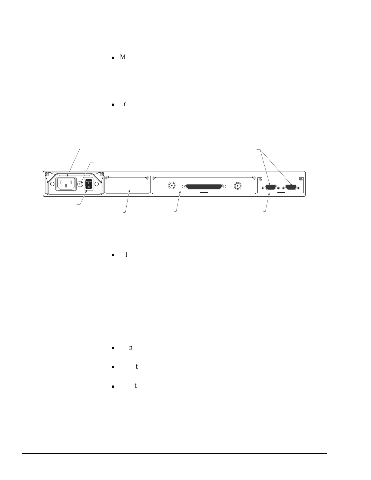
4-6 Installation
Step 3:
Familiarize Yourself
with the C M 601 Chass is
The followin g labels and identification tags are found on the CM601 chassis:
Model – appears on the front panel in the upper-left corner and contains the
CM601 model number
The CM601 model number applies to the standard, full-duplex modem
configura tion and any oth er con fig urations tha t use option c ards to e xpand the
capabilities of the standard CM601 modem.
Product serial number – found on the top cover.
This label contains saf ety and emissions agency certifications and the unit
serial number.
Figure 4-1 CM 601 Rear Panel
Filler plate c ard – included on the rear panel filler plates of each installed card
Each of the fille r plates contains information that has been silk-screened onto
the metal. Thes e la bel s inc lude the card name and ref eren c e de signator for
each connector.
Issuing Commands
In order to ente r the necessary command s to complete both the bench- top test and
initial configuration of the CM601, determine if commands will be entered
through the front panel, a remote terminal, or both. If commands will be issued
through:
Front panel - review the chapter on front panel operations to become familiar
with the front panel, the command tree structure, and front panel commands
Remote terminal - review the chapter on remote operations to familiarize
yourself with the available remote commands and their syntax
Both the front panel and a remote terminal - review both chapte rs on CM601
command operations
H097-01
J3: TxIF
J5: RxIF
Low Speed Modem
J1:Remote Control
J2:Status Relay
J4: Tx/Rx Data RS-449
IEC AC
receptacle
Slot 5
Modem card
Slot 1
Option card
Female D
connectors
Slot 4
M&C card
On/Off
Switch
Ground
Stud
Page 51

Installation 4-7
Step 4:
Perform a Bench-Top
Test
It is important to p erform a bench-to p test pri o r to C M 6 01 system installation in
order to verify proper configuration and to confirm that the hardware capa bilities
match the application. This important step can help you avoid schedule and
budget impacts , as it helps you to identify and resolve cabli ng problems or system
requirement incompatibilities prior to installation.
The test sequence in this secti on is written for a CM601 configured as a basic
SCPC modem.
Equipment Requirements
The bench-top test requir es :
Asynchronous RS-232 terminal, or a personal computer with a terminal
emulator program or ComStream’s QuickLink.
RS-232 serial port
AC power access
Test Procedure
When following the bench-top test procedure, note that the exact location of the
connector J numbers may va ry from one CM601 to another, depending on the slot
location of the cards. Check the silk-screen labels for the location of the cards a nd
associated connector J numbers. To perform the bench-top test:
1. Place the CM601 on a bench or tabletop.
2. Make sure that the AC switch is in the Off positi on.
3. Connect the remote terminal , if it will be used to issue commands:
a. Attach a 9-to-25-pin adapter cabl e to the termi nal and the connector
labeled Remote Control ( J1) located on the rear pane l. Table 4-1 contains
the pinout specifications for a DB-9, straight-through cable for use with
personal computers.
Table 4-1 Straight-Through Cable
Pinout Specifications
Male Female
11
22
33
44
55
66
77
88
99
Page 52
4-8 Installation
b. Configure the terminal as follo ws:
• 7 data bits
• Odd parity
• 1 stop bit
• 1200 baud
4. Select an AC power cord and connect it to the CM601 IEC receptacle on the
rear panel, and plug the other end into an AC outlet. For additio nal
information on the powe r source and rules and regulations fo r atta ching an
international power cord, refer to the Preface of this guide.
5. Power on the CM601. Press the rear panel rocker switch toward the On
position.
6. Monitor the message sequences on the front panel and remote terminal
displays. The power-up message sequences are presented in Table 4-2.
Table 4-2 Power-Up Sequence
Front Panel Power-Up Sequence Remote T e rminal Pow e r -Up Sequence
LEDs illuminate for a short time while all
LED lamps are tested
CM601 information appears; for example:
ComStream CM601
ID message
Unit serial number
Pass or fail indication for the power-up,
self-test sequence
Power-Up Test Messages:
Power-Up Test in Progress
Power-Up Test Complete
message indicating the test passed or
failed
Information for each card installed in the
CM601 chassis appears:
Card description
Chassis slot location
Software version
Other hardware configuration information
ComStream CM601
identification
message appears indicating power-up is
complete
System prompt (>) appears indicating
power-up is complete
Troubleshooting Tip
If the terminal fails to display the power-up message sequence, check the following:
Cables
Remote terminal baud rate set at 1200
Terminal data/parity set at 7/odd
Once the parameters ar e correct, turn the powe r switch off and then back on. Monitor the powerup message sequence on the remote terminal.
Page 53

Installation 4-9
7. Verify front panel button operation. To do this, select the following opti ons in
the order in which they are listed, using the buttons on the front panel:
8. Verify remote operation fr om the remote terminal keyboard. To do this, at the
system prompt, type
EM ?
and press
E
NTER.
A response of
EM 1 or EM 0
should appear on the displa y follo wed by the
system prompt >.
9. If the optional BERT option is installed, perform a BERT loopback test to
verify basic modem operation. For additional information on the BER T IF
Loopback test, refer to the chap ter on troubleshooting and the BERT
appendix.
T o p erf orm the loo pback te st, th e IF loopba ck ca ble pr ovide d must be a ttac hed
between the TxIF connector and the RxIF connector on the modem card.
Additional Testing
Additional testing may be performed if test equipment is available and extensive
specification compliance is necessary. Specification compliance tests for RF
power, dynamic range, acquisition range, acquisition time , symbo l rate range,
aggregat e power, and many other parameters can be performed.
For informa tion on tests specific to option cards installed i n a CM601, refer to the
specific user guide that accompanies each option card.
Completion of the Bench-Top Tes t
The CM601 system is now tested and ve rified. This concludes the bench-top
functional verification test sequence for the CM601. If no further testing is
required, power off the unit and proceed to the next section.
Table 4-3
Front Panel Button Operation Verification
Button or Option LCD Message Display Remarks
Any LCD button Config Monitor Faults These buttons are located directly below the
LCD and have t -shaped icons above them
Config 4:Systm4:M&C More —
More 5:Modem More —
5:Modem TxDataRate TxDataRat e is the first of the list of modulator
commands that appears
Previous but ton 5:Modem More —
Previous but ton Config Monitor Faults —
Page 54

4-10 Installation
Step 5:
Install and Connect the
CM601 in a Permanent
Location
It is important that all rack-mount installations allow adequate ventilation to the
modem at all times. To keep the system cool and running smoothly , the power
supply cooling fan e xhausts air through an opening on the po wer supply side of
the modem and pulls e xternal air in through openings on the other side of the unit.
The minimum airflow clearance space is three inches at the sides of the CM601.
In addition, there should be six inches of clearance at the rear for cabling.
To install and connect the CM601:
1. Install the CM601 in a standard 19-inch rack, if appropriate.
a. There are four screw holes in the front of the unit used to mount the
CM601 to the rack.
b. Install the CM601 in the rack.
2. Attach all external system connections after the unit has been positioned.
Since the connector J numbers and card locations may vary, use the silkscreen labeling to identify their locations. (Refer to Figure 4-1.)
a. Place the AC switch on the CM601 in the Of f posi tion.
b. Connec t the CM601 ground stud, located to the lower right of the power
cord on the rear panel, to the rack gr ound, or to another solid connection
to earth ground with heavy gauge wire.
c. Connect the IF coaxial cables to the modem card’s TxIF and RxIF
connectors.
d. If remote operation is desired, connect the RS-232 plug of an
asynchronous data terminal to the remote control DB-9 (J1) connector.
The CM601 shipping kit inc ludes a male-DB-9-to-female -DB-25 adapter
cable that can be used to convert the 9-pin remote control connector to a
standard, 25-pin, RS-232 DCE pinout.
For systems requiring packet protocol remote operation, connect a
personal computer with suppor ting packet driver software directly to the
Remote Control (J1) connector. For details on packet-based remote
communications, refer to the CM601 Reference Guide.
e. Connect a cable, appropriate for the selected data interface, to the Tx/Rx
data connector and the DTE.
For detai led specific ations about the mode m card’s data interface, refer to
the chapter on exter nal connections. For detailed specifications for the
Data I/O option card data interface, refer to the specific user guide that
accompanies each option car d.
f. Select and connect an AC power cable to the CM601 IEC receptacle on
the rear panel, and plug the other end into an AC outlet.
If an international AC power cable is selected, a locally compatible plug
must be attached to the stripped and tinned bare wires of the cable in
accordance with any local laws or regulations.
Page 55

Installation 4-11
For informati on on installation and rules and regulations for interna tional
AC power cords, refer to the chapter on external connections and the
appendix on technical spec ifications. For a list of certifying agencies for
various countries, refer to the “Safety Precautions” section in the Preface
of this guide.
Make sure that the AC switch on the CM601 rear panel is in the Off
position before conne cting the AC power cable .
3. Power up the CM601 by performing the following steps:
a. Pre ss the rear p anel ro cker switch toward the On position.
b. Monitor the message sequences on the remote terminal as described in
Table 4-2.
For application s using packet prot ocol for remote operation s, no power -up
messages are issued by the CM601. For detailed information on packet
protocol specifications, refer to the CM601 Reference Guide.
Step 6:
Configure the CM601
The CM601 can accommodate a variety of configurations to allow for
customization of your network communications system. To configu re the CM601:
1. Use the front panel or remote terminal to configure the CM601 accordi ng to
your system design and operating parameters.
For a complete listing of fr ont panel or remote commands, refer to the
chapters on front panel or remote operations, as appropriate. For detailed
command information, refer to the CM601 Reference Guide.
2. After the system has been configured, verify the parameter settings by issuing
the Display Parameters commands
DP
and
DP 7
to display the summary
configura tion parameter settings.
If it is necessary to start the configuration process over or to reconfigure an
existing unit, the CM601 may be restored to its original factory configuration
using the Initializ e Nonvolatile Memory command:
From a remote unit:
IN 9346
From the front panel Config>Systm list:
Init Factory Default
If the CM601 is configured fo r nonstandard data paths, those paths may be
overwritten during initialization.
Page 56
4-12 Installation
Acquire the Carrier
In a standard conf igurat ion, the CM601 automatic ally acqui res the c arrier i n a few
seconds when the:
Eb/N0 level is greate r than 4 dB
Symbol rate is greater than 200 ksps
The following occurs when carrier acquisition is complete:
Rx Sync message on the front panel changes from white to green
Unsolicited
ST 0
message appears on the ASCII remote terminal screen
If the modem does not acquire the carrier within a few minutes, an acquisition
failure error code will display. If this occurs, ensur e that:
External connecti ons are attached correctly to the other equipment
Configura tion parameters on the modem card are compatible; change the
parameters as needed
Modulator output is enabled by issuing EM 1
Signal-to-noi se ratio is suff icient for operation
Modem has searched the entire acquisition range; check the AR parameter
Signal is present on the RxIF connector
Receive carrier is at the expec te d freq u ency
AG parameter is at an acceptable level
Value of 60 to 170 indicates good signal leve l
Value of 255 indicates no signal
For additional help in solving common acquisition problems, refer to the chapter
on troubleshooting and maintenance.
Acquisition Commands
Use the remote terminal or the front pan el to issue the c ommonly used acquis ition
commands shown in Table 4-4.
For detailed command inf ormation, refer to the CM601 Reference Guide.
Table 4-4 Commonly Used Acquisition Commands
Command Function Remote Command Front Panel Command
Acquisition Offset Frequency AO None*
Acquisition Mode AQ Acquisition
Acquisition Range AR None*
Receiver Carrier Offset RO Rx Offset
* This entry does not appear on the front panel. Use the front panel terminal emulator (:AA) to enter this command from
the front panel.
Page 57

Installation 4-13
Step 7:
Validate the Syst em
To validate the system and isolate system fault s, the tests described in Table 4-5
can be performed using the modem loopback (MLB) command.
Remember to perform the series of loopback tests from both ends of the satellite
link. This will en sur e that each mod em is receiving the carrier from the satellite
with an acceptable E
b/N0
level withi n the anticipated link availability. Typic al
leve ls range from 6 to 10 dB.
For detailed testing information and procedures, refer to the chapter on
troubleshooting and maintenance.
Table 4-5 CM601 System Tests
Test Description
Near data loopback Validates the connection between the DTE and the CM601.
IF loopback Vali dates IDU operation; can only be performed using an external
loopback cable.
Satellite loopback Validates the coaxial cabling between the CM601 and the RF equipment;
confirms the radio transmit and receive paths and the satellite receive and
transmit paths.
Far data loopbac k Validates the entire transmit and receiv e paths between t he near-end DTE
and the far-end modem. The far-end modem must be in far data loopback
mode.
Long-term BER
measurement
Indicates if the:
Satellite link is operational 24 hours a day, 7 days a week, with no
periodic interruptions along the way
Doppler effects of satellite motion on the circuit operation are
nonexistent, or at least within tolerance
This test should be perform ed for one week but at a minimum should be
conducted for at least 24 hours.
The one-week duration is optimum, as neighboring carriers on the satellite
may interfere only at certain times during the week.
This test can be run with an external DTE data integrity tester or the
internal, built-in, BERT a vailable on certain modem cards.
Page 58

4-14 Installation
Step 8:
Optional Front Panel
Lockout
For some installa tions, the front panel may need to be disabled. For the se
applications the CM601 provides view-only and complete front panel lockout
modes. These modes prohibit accide ntal or unauthorized modific ations to the
CM601 operating configuration. Since the lockout configuration parameter is
stored in NV memory, it remains unchanged after a CM601 reset or po wer-up.
Issuing the Front Panel Lockout Command from the Front Panel
To lock out the front panel, change from one lockout mode to another, or return
the front panel to normal operation, perform the following steps:
1. Access the front panel LockOut command by pressing the Previous, Up
Modify, and left Cursor buttons
Previous^<
simultaneously (t hese three
buttons are presse d together). The LCD will display the message
Front
Panel No rma l
.
2. Press the right LCD button or a Cursor button so that Normal is blinking.
3. Press the right LCD button to scroll through the parameter list until the
desired configuration is found. Each button press scrolls to the next item on
the parameter list. Available parameters are:
Normal – all features are enabled; front panel is fully functional
ViewOnly – front panel responds to all push buttons, except Enter and
Tx Enable, to allow you to read all operating parameters and
configuration parameters, but not change parameters; this mode is
indicated by a yello w ViewOnly message on the front panel to the right of
the LCD display and above the Enter button
LockOut – this mode is indicated by the message
Front Panel LockOut
on the LCD; while this mode is active , all
button press es are ignored except the
Previous^<
button sequence
4. Press the Enter button to issue the command. The front panel is set at the
desired operatin g mode.
Issuing the Front Panel Lockout Command from a Remote Unit
To lock out the front panel, change from one Lockout mode to another, or return
the front panel to normal operation, issue the following remote commands:
To lock out the front panel, issue an
FPL 2
command. While this mode is
activ e, all front panel button presses are ignored.
During lockout mode, the front panel will only acknowledged the following
three-bu tton sequence
Previous^<
(these three butt ons are pressed
together). When this front panel command sequence is entered, users are able
to modify the front panel lockout parameters from the front panel
To place the front panel in ViewOnly mode, issue an
FPL 1
command. The
front panel will respond to all button presses
except
the Enter and Tx Enable
buttons. This mode allows users to view, but not change, CM601 parameters,
status information and other information displayed on the front panel LC D.
T o rest ore the front panel to Norma l mode, issue an
FPL 0
command. The front
panel will be fully functional with all features enabled.
Page 59
Remote Commands and Error Codes 5-1
5
Remote Commands
and Error Codes
This chapter presents the following information:
An overview of remote communications
Instructions for issuing commands from a remote terminal
Definiti ons of command memory types, command function types, and error,
fault and status code s
Summary and brief descripti on of CM601 commands used with a standard
CM601 configurat ion. The standard CM601 configurati on consists of a LowSpeed Modem card and an M&C card; there are no option cards installed in
slot one.
Remote
Communications
Overview
All CM601 commands can be issued f rom a remote terminal. A compatible
remote terminal could be an ASCII computer terminal, a personal computer, or
any other control unit c apable of asynchronous communications. The CM601
remote port can be configured to support RS-232 or RS-485 electrical levels.
ASCII and ComStream Packet Protocol
The two types of remote communicati ons protocols supported by the CM601 are
ASCII and ComStream packet protocol. ASCII protocol is provided for use with
character-bas ed co mputer terminals. These terminals issue an asynchronous
ASCII character to the CM601 each time a keyboard key is pressed. If the echo
enable parameter (EE) is set to 1, the CM601 echoes the character back to the
terminal for display on the screen.
ComStream packet protoc ol was developed for computer control of one or more
ComStream products on an RS-485 multidrop or party-line control bus.
ComStream packet protoc ol is also used by network management systems to
control a remote CM601 through an in-band channel provided by a satelli te
control channel option card. F or a detailed explanation of the packet structur e and
features of this protocol, refer to the CM601 Reference Guide.
Configuration
The remote port confi guration selections are made remotely using the BR, MDP,
MEI, MPT, and MPA commands. Selections for RS-232 or RS-485 electrical
interface, communications baud rate, data and parity bits, ASCII or ComStream
packet protocol, and packet protocol device address are explained in detail in the
CM601 Reference Guide.
Page 60
5-2 Remote Commands and Error Codes
Issuing Commands To issue a CM601 command, type the command at the prompt (>) with the
appropriat e parameter, and then press
E
NTER. Use the following syntax:
<command mnemonic> <parameter>
where:
<command mnemonic>
refers to a two- or three-letter command
abbreviation
There must be one space betwe en the command mnemoni c and the pa rameter;
a spa ce is inser ted by pr e s s in g the
S
PACE BAR
.
<parameter>
is any value pe rtaining to the command, if applicable
The parameter for a query command is a question mark (?); some commands
do not require a parameter.
For example:
To set the real-ti me date (DAY) as March 4, 1999 (030499), use the syntax
DAY 0304 99
.
To query (?) the recei ve synthesizer frequency (RS), use the syntax
RS ?
.
To display a list of command parameters, use the syntax
DP
.
For redundant configurations, a slot number must precede the command:
<slot number>:<command mnemonic> <parameter>
Direct slot addressing of commands is not required for most CM601
configura tions. It is required only when multiple option cards are in stall ed with
identical command mnemonics. For example:
To query (?) the recei ve timing clock frequency (RTF) for slot 1, use the
syntax
1:RTF ?
.
Command Summary CM601 commands can be categorized into two memory type s and four functiona l
types. Memory types of configuration commands are listed in Table 5-1.
Command functions are listed in Table 5-2
Table 5-1 Configuration Command Memory Types
Memory Type Description
Nonvol ati le (NV) Command parameters that are stored in NV memory do not have
to be reentered each time the CM601 is powered on or reset.
Volatile (V) Command parameters that are stored in volatile memory are not
retained after power-on or reset of the CM601.
Page 61

Remote Commands and Error Codes 5-3
.
CM601 commands are summarized in alphabetical order in T able 5-3. For each
command the follo wing inf ormation is provided:
Command mnemonic
Command name
Function and memory type
Parameter range: a hyphen (-) i n this co lum n indicates that the command can
be issued with no parameter
Default va lue
Brief description or notes
Detailed descript ions of these commands are provided in the CM601 Reference
Guide.
Table 5-2 Comma nd Funct ion Types
Function Description
Configuration These commands have parameters that can be modified and entered to
change the operating characteristics of the CM601 and direct it to perform
real-time functions.
Monitor These commands provide query (view-only) information about the
performance, operating environment, and nonfault-related conditions of
the CM601.
Fault These commands provide information about the functional status of the
CM601 and may indicate when an external piece of equipment is not
configured properly or is faulty. Fault commands are query-only with the
exception of the Clear Faults (CF) command.
Security These commands control access to the remote port to prevent
unauthorized operation of the CM601 over telephone lines or other types
of remote access.
Page 62

5-4 Remote Commands and Error Codes
Table 5-3 Command Summary
Command
Mnemonic
Command Name
Function
(Mem Type)
Parameter Range D efault Description and Notes
ABB Acquisition Bits P er
Bin
Config (NV) 1 to 255 1 Reduces the amount of time demodulator waits
in a bin during acquisition; reducing time not
recommended for low Eb/No applications.
ACP Autoconfiguration
Path
Config (NV) 0 = disable
1 = enable
1 Enables or disables the autoconfiguration path
function; during CM601 power-up or reset
autoconfiguration default settings are
reestablished if ACP is enabled.
AE Automatic
Modulator Enable
Config (NV) 0 = manual
1 = automatic
1 Enables or disables the modulator TxIF at
modem power-up, issuance of the reset (RE)
command, or upon resolution of a modulator
fault condition.
AG AGC Level Monitor ? — Displays gain factor applied to the received
signal; response values: 0 t o 255; a low value =
strong receive signal; a high value = weak
receive signals.
AL Alarm Reporting Conf ig (NV) 0 = disable
1 = enable
3 = disable
1 Enables or disables fault reporting; allows or
prevents unsolicited fault messages from being
issued by the CM601 to a remote terminal.
Available only with ASCII remote protocol;
packet protocol does not allow any unsolicited
messages.
AO Ac quisition Offset
Frequency
Config (NV) -30000 to +30000 0 Sets the offset frequency from which the
acquisition search will begin; frequency is
expressed in hertz.
AQ Acquisition Config (NV) 0 = disable
1 = enable
2=fast
1 D eterm ines acquisition status of the
demodulator or to restart acquisition.
AR Acquisition Range Config (NV) 0 to 500000 30000 Defines the size of the frequency range over
which the demodulator will search for the
carrier. The acquisition range is expressed in
hertz.
BBC Bert Bit Count BMonitor ? — Displays the bit count since the last BER T sync
or re set.
BBE Bert Block Ber BMonitor ? — Displays the BER over the previous block;
BERT block length is defined in the BBL
command.
BBL Bert Block Length BConfig (NV) 1 = 1 sec
5 = 10
5
bits
6= 10
6
bits
7=10
7
bits
8=10
8
bits
6 Establishes the block length used by the BERT
for error analysis; the number of bits in a onesecond block equals the current data rate in
units of bits per second.
BDI Bert Data Inverted BMonitor ? — Determines if the BERT receive data is
inverted; response values: 0 = not in v erted, 1 =
inverted.
BDP Bert Display
Parameters
BMonitor — — Displays a summary of all current BERT status
parameters.
BEC Bert Bit Error
Count
BMonitor ? — Displays the bit error count since the last BERT
sync or reset.
BEI Bert Error Insert BConfig (V) — — Inserts a single error in the BERT transmit data
stream; typically used to validate the link
between two units with both BERTs enabled.
Error displays if issued when BERT is disabled.
BEN Bert Enable BConfig (V) 0 = disable
1 = enable
0 Enables or disables the BERT; during normal
operation, the BERT must be disabled for the
CM601 to pass user data.
Page 63

Remote Commands and Error Codes 5-5
BER Bert Average BER BMonitor ? — Displays the av erage bit error rate since the last
BERT sync or reset.
BIT Built-in Self-test Config (V) 0 — Performs a built-in, board-lev el self-test f or all
installed cards; a response other than
X:XXXXX PASS (0), where X:XXXXX is the slot
# and card type, indicates a hardware failure.
BLC Bert Block Count BMonitor ? — Displays the block count since the last BERT
sync or reset; BERT block length is defined in
the BBL command.
BLE Bert Average Block
Error Rate
BMonitor ? — Displays the block error rate since the last
BERT sy nc or reset; block error rate is the
number of blocks with errors divided by the
number of blocks of received data. BERT block
length is defined in the BBL command.
BPT Bert Pattern Type BConfig (NV) 0 = 2^9-1
1 = defined by BUP
2 = 1:1
3 = mark
4 = space
5 = 2^15-1
0 Establishes pattern type for transmission and
reception.
BR Baud Rate Config (NV) 75, 300, 1200, 2400, 4800, 9600 1200 Sets the asynchronous communication baud
rate for the remote port; the baud rate of the
CM601 must match the baud rate of the remote
device.
BRC Baud Rate Custom Config (NV) 62 to 19200 1200 Sets a custom, asynchronous communication
baud rate for the remote port; the baud rate of
the CM601 must match the baud rate of the
remot e device.
BRE Bert Reset And
Control
BConfig (V) 0 = stop
1 = start
2 = reset
2 St ops, start s, or resets the BERT.
BSF Bert Sync Fault
History
BMonitor ? — Determines if the BERT has stayed in
synchronization since the last BERT reset.;
return values: 0 = remained in sync, 1 = lost
sync at least once.
BSS Bert Sync Status BM onit or ? — Determines if the present synchronization of
the BERT is in or out of synchronization;
synchronization based on detection of fewer
than n error bits out of m received bits, where n
and m are defined in the BST command;
return
values: 0 = in sync, 1 = not in sync.
BST Bert Sync
Threshold
BConfig (NV) 0 = low 1,000 errors in 10000 bits
1 = high 2,500 errors in 10000
bits
0 Sets the threshold for the BER and determines
if synchronization exists between the BERT
and the received data.
BUP Bert User Pattern BConfig (NV) 0 to 255 85 Establishes an 8-bit, user-programmable
pattern for BERT transmit and receive; the
BERT cycles the pattern through a shift register
that continuously repeats the pattern.
BWE Bert Block Error
Count
BMonitor ? — Displays a count of all blocks containing one or
more errors since the last BERT sync or reset;
BERT block length defined by BBL command.
CAP Current Active Path Config (V) 0 = all
1 = primary
2 = secondary
3 = ternary
0 Sets the data path to which subsequent
commands will be issued.
Table 5-3 Command Summary (continued)
Command
Mnemonic
Command Name
Function
(Mem Type)
Parameter Range D efault Description and Notes
Page 64

5-6 Remote Commands and Error Codes
CAS Current Active
Status
Config (V) 0 = all; 1 = primary
2 = secondary; 3 = ternary
0 Sets the data path to which a status query
command will be issued.
CD Control Data Mode Config (NV) 1 = ignore
2 = respond
1 Sets the CM601 to monitor and respond to, or
ignore, DCE-DTE data control signals.
CE Channel Error Rate Monitor ? — Queries the channel error rate only if the
demodulator is operating with FEC decoding
enabled; if CE is issued when the CM601 is not
locked to a receive carrier, or if the CM601 is
operating uncoded, an ER 4 error response
message appears; return values format is mn
(representing m x 10-n).
CF Clear Fault Log Faults (V) — = clear
0 = clear
— Clears the fault log and current fault lists.
CFG Card Conf iguration Monitor ? — Displays CM601 installed cards; responses
include the slot number and a code indicating
the type of card installed in the slot.
CLP Clear Path Conf ig (V) 0 = clear 0 Clears all data paths; same affect as issuing a
0 parameter with each of the transmit and
receive data path commands.
CPC Conf iguration Path
Control
Config (V) 1 = enable 1 Enables the confi guration pat h c ontrol f unction;
when CPC is issued, autoconfiguration default
settings are reestablished.
DAY Internal Dat e Config (NV) MoDaYr:
Mo = 01 to 12
Da = 01 to 31
Yr = 00 to 99
0 = clock off
— Sets the CM601 internal real-time date; real-
time date is expressed in two-digit format; time
is factory set to U.S.A. Pacific standard time; no
default; IN 9346 or INF 9346 does not reset
value in NV memory.
DB Doppler Buffer F ill
Level
Monitor ? — Displays the number of data bits currently in the
data buffer.
DBB Doppler Buffer S ize Config (NV) 64 to 8192 8192 S et s the size of the data buffer in bits; invalid
entries are rounded up to next valid size. To set
the data buffer by entering the buffer length in
milliseconds, use the DBD command.
DBD Doppler Bu ffer
Delay
Config (NV) 1 to 1000 853 Sets the buffer length in milliseconds
throughout the entire buffer; the buffer normally
runs at 50 percent full, so the delay t hrough the
buffer is typically half that of the entered
parameter; invalid entries are rounded up to
next valid size; aut o sets DBB.
DBM Doppler Buffer
Mode
Config (NV) 0 = enable buffer
1 = enable bypass
1 Enables buffer or bypass mode; data does not
pass through Doppler buffer in bypass mode.
DBR Doppler Bu ffer
Reset
Config (V) — — Reset the Doppler buffer; when the buffer is
reset, the input and output pointers are set to
the half-full point (50%).
DC Display
Configuration
Config (V) — and 0 = modem format
1 = symbol rates format
7 = CM601 modular format
— Sets the format in which the current CM601
configuration will be displayed; supported by
ASCII protocol only.
DCS Doppler Clock
Selec t
Config (NV) 1 = user-supplied transmit timing
4 = internal clock or send timing
4 Selects the clock used to clock data out of the
Doppler buffer.
DD Differential
Decoding On
Demodulator
Config (NV) 0 = disable
1 = enable standard, all except
QPSK uncoded
2 = enable standard/QPSK
uncoded
1 Contr ols differential decoding on the
demodulator.
Table 5-3 Command Summary (continued)
Command
Mnemonic
Command Name
Function
(Mem Type)
Parameter Range D efault Description and Notes
Page 65

Remote Commands and Error Codes 5-7
DFL Doppler Buffer Fill
Level
Monitor ? — Displays the fil l level of the data buffer; the level
is expressed as a percentage.
DFS Demodulator
Baseband Filter
Selec t
Config (NV) 0 = ComStream closed network
1 = Intelsat-compatible, open
2 = Eutelsat-compatible, open
0 Selects the demodulator baseband digital filter
spectral shape; demodulator’s digital filter
creates an optimal match to the modulator
baseband filter, which results in exceptional
modem performance.
DI Demodulator
Spec tra l Inversi o n
Config (NV) 0 = disable
1 = enable
0 Enables or disables the demodulator spectral
inversion.
DL Decoder Memory
Length
Config (NV) 0 = short (128)
1 = long (4096)
2 = automatically selects short or
long memory based on symbol
rate
2 Controls the decoder path memory length for
the sequential decoder on the demodulator;
sequential decoder can operate with 128 bits or
4096 bits of path memory. A shorter memory
length provides less throughput delay (128 bit
delay versus 4096 bit delay), however, a longer
memory provides better performance at data
rates above 64 kbps.
DM Differential
Encoding On
Modulator
Config (NV) 0 = disable
1 = enable standard, all except
QPSK uncoded
2 = enable standard/QPSK
uncoded
1 Controls differential encoding on the modulator.
DP Display Parameters Config (V) - or 0 = summary
1 = operating mode
2 = operating performance
indicators
7 = CM601 modular format
— Displays a summary of current modem
configuration and operating parameters; DP
command is not supported by ComStream
packet protocol.
EB E
b/N0
Level Monitor ? — Displays current Eb/N0 lev el; response values:
0.1 dB steps from 0 to 21 dB; if issued when
the modem is not locked to a receive car rier, an
ER 4 displays.
EBT E
b/N0
Threshold Conf ig (NV) 0 to 210 0 Sets the Eb/N0 threshold used during fault
reporting; set in 0.1 dB steps from 0 to 21 dB.
EE Echo Enable Config (NV) 0 = disable
1 = enable
1 Enables or disables the echoing of characters
back to the remote terminal when they are
received by the modem; used with ASCII
protocol only and has no effect on packet
protocol operation.
EM Enable Modulator Config (NV) 0 = disable
1 = enable
1 Enables or disables the modulator TxIF output
power; if the modulator is stable and without
faults, the TxIF power can be enabled. If
hardware faults ex ist or the synthesizers are
not stable and locked, the modulator power
cannot be enabled, and an error message will
be displayed if this is attempted.
FL Fault History Log Fault ? — Displays the fault history log; response values:
decimal number representing contents of 32-bit
fault log register.
FLO Fault Log Overlay
Mask (Yellow Fault
LED)
Config (NV) 1 to 4294967295 4294967295 Designates the fault log conditions that will
affect the yellow fault LED located on the
CM601 front panel.
FO Current Fault
Overlay Mask
(Status Re lay)
Config (NV) 1 to 4294967295 4294967295 Designates the current fault conditions that will
affect the status relay on the CM601 rear panel.
Table 5-3 Command Summary (continued)
Command
Mnemonic
Command Name
Function
(Mem Type)
Parameter Range D efault Description and Notes
Page 66

5-8 Remote Commands and Error Codes
FR Fault Relay Sense Config (NV) 0 = normal
1 = inverted
0 Changes the polarity of the Form-C status relay
accessed through the J2 connector on the rear
panel of the CM601.
FRX Fault Relay Sense
External Signal
Polarity
Config (NV) <condition> parameter = 0 to 7
bit settings:
0 = normal polarity
1 = inverted polarity
0 (bit setting) Defines whether a fault condition is a closed or
an open relay contact for each of the three
external fault relay sense pins on the Status
Relay rear panel connector.
GAV Gate Array Version Monitor syntax is n:GAV ? where n =
1, 4, or 5
— Displays the version of the installed EPROM by
slot .
HWV Hardware Version Monitor syntax is n:HWV ? where
n = 1, 4, or 5
— Displays the hardware version of any card in
the modem by slot; response format:
<slot#>:V<version number>.
ID Modem
Identification
Config (NV) 1 to 24 ASCII characters ComStream
CM601
Assigns an arbitrary, 24-character ASCII string
used to identify the modem.
IN Initialize Modem Config (V) 9346 — Initializes all modem configuration parameters
to their default states, stores them in NV
memory, and then performs a complete modem
rese t .
INF Initialize New
Firmware
Config (V) 9346 — Initializes and resets all option cards; all
configuration parameters are returned to their
default settings and the NV memory map is
reconfigured. Use this command anytime new
firmware is added to any CM601 card,
including M&C firmware, to ensure proper
operation after installation.
LB Loopback Mode Config (V) 0 = disable
2 = near data
4 = far data
0 Tests and troubleshoots system connections.
LBT LCD Backlight
Timeout
Config (NV) 0 = always off
1 to 19 = minutes to time-out
20 = always on
— Sets the number of minutes until the front panel
LCD backlight is automatically turned off
LCC LCD Contrast Config (NV) 0 to 10 with 0 = lightest setting,
10 = darkest setting
Adjusts the contrast on the front panel LCD .
LGE Login Security
Enable
Security (NV) 0 = disable
1 = enable
0 Enables and disables the remote login port
security function.
LGN Login Security (V) 1 to 8 alphanumeric characters,
no embedded spaces
password L ogs in to the remote port and establishes
normal communications with the CM601. When
LGE is set to 0, this command is not available
and returns an error message.
LGT Logout Security (V) — — Logs out from the remote port; use this
command if LGN was used to establish
communication.
LIT Login Inactivity
Time-out
Security (NV) 0 = disable
5 to 255
60 Sets the number of seconds of inactivity
allowed before automatic logout occurs.
LPW Login Password Security (NV) 1 to 8 alphanumeric characters,
no embedded spaces
— Changes the remote port login password.
MB Modulator Bit
Timing
Config (NV) 1 = external timing
2 = internal timing
3 = loop timing
2 Establishes the source of the modulator bit
time, transmit data clock. The DTE must
provide the CM601 with send data (SD) that
transitions on the rising edge of the selected
transm it cl ock.
Table 5-3 Command Summary (continued)
Command
Mnemonic
Command Name
Function
(Mem Type)
Parameter Range D efault Description and Notes
Page 67

Remote Commands and Error Codes 5-9
MCS M&C Clock Select Config (NV) 0 = not through M&C card
1 = SMA to TTL terminated
2 = SMA to TTL unterminated
3 = 15-pin D status relay to
differential RS-442A receiver
terminated
0 Selects the interface and connector type used
on the M&C card to receive an external bit
timing clock. If value 1, 2, or 3 is selected, this
clock is routed over the CM601 backplane for
use by circuits on other boards. Currently this
command is only available when us ing the high
stability M&C car d .
MD1 -
MD9
Modem Data Config (V) one or more CM601 commands
separated by semicolons, up to
120 characters
— Used when controlling a remote modem
through an SCC option card; each modem data
commands is associated with an individual
buffer that can store a CM601 remote
command string for later transmission to the
modem chassis.
MDC Modem Data Clear Config (V) - = clears all buffers
1 to 9 = clears specific buffer
— Clears the specified MD buffer (MD1 through
MD9); no parameter clears all MD buffers.
MDP Modem Data Parity Config (NV) 0 = 7 data bits with odd parity
1 = 8 data bits with no parity
0 Sets the remote format; asynchronous
character format for the CM601 remote
interface is independent of packet or ASCII
remote protocol selection.
MDR Modem Data Time
Remaining
Monitor - or ? — Determines the number of seconds remaining
until the MD buffers are executed; if MDT is not
active, returns an ER 4.
MDS M odem Data Stop Config (V) — — Stops the MDT process and clears the MDT
value; if the MDS command is issued after the
MD buffers hav e begun to execute, it is ignored.
MDT Modem Data Time Config (V) absolute: 00:00:00 to 23:59:59
seconds: 0 to 172800
— Sets the time (or time delay) for executing the
commands buffered in the MD commands; time
value can be entered in absolute time or in
seconds. The absolute time is relative to the
CM601 real-time clock.
MEI Modem Electrical
Interface
Config (NV) 0 = RS-232
1 = RS-485
0 Sets remote port to RS-232 or RS-485.
MFS Modulator
Baseband Filter
Selec t
Config (NV) 0 = ComStream closed network
1 = Intelsat-compatible, open
2 = Eutelsat-compatible, open
0 Selects the spectral shape of the modulated
TxIF signal; modulator digital filter coefficients
are programmed to create an optimal match to
the demodulator baseband digital filter, which
results in exceptional modem performance.
MI Modulator Spectral
Inversion
Config (NV) 0 = disable
1 = enable
0 Controls the transmit spectral inversion feature
on the modulator .
ML Modulator Latching
Clock
Config (NV) 0 = TT clock
1 = ST clock
1 Selects the clock to be used by the modulator
to latch the transmit data (SD) into the CM601;
when the modulator is using external timing,
this command has no effect and the TT clock is
always selected.
MLB Modem Card
Loopback Mode
Config (V) 0 = disable
2 = near data
4 = far data
0 Tests and troubleshoots system connections
when the data I/O interface on the modem card
is used instead of a data I/O card.
MPA Modem Packet
Addres s
Config (NV) 1 to 31 1 Sets the device address when packet protocol
is selected for the remote protocol. The Packet
Address command is not used with ASCII
protocol operation.
MPT M odem Protocol
Type
Config (NV) 0 = ASCII
1 = ComStream packet
0 Selects the protocol used for the CM601
remote port.
Table 5-3 Command Summary (continued)
Command
Mnemonic
Command Name
Function
(Mem Type)
Parameter Range D efault Description and Notes
Page 68

5-10 Remote Commands and Error Codes
MQE Modem Quer y
Execute
Monitor ? — E xecutes the current modem query list and
returns the first result buffer; this command is
available after you enter a modem query list
with the MQL command.
MQL Modem Query List Config (V) One or more CM601 command
mnemonics, up to 120 characters
separated by commas
— Combines multiple queries into single
command; list is executed by the MQE
command.
MQN Modem Query Next Monitor — — D isplays the next modem query list result
buffer; when additional data remains in a
modem query list result buffer, the last
character of the first buffer response to the
MQE command is a plus sign (+).
NVO Nonvolatile
Memory Override
Config (NV) 0 = normal operation
1 = NV override on
0 Inhibits writing to NV memory when a NV
command is entered.
OM Override Modulator
Bit Time Fault
Config (NV) 0 = disables TxIF output
1 = does
not
disable TxIF output
0 Controls the automatic actions performed by
the modulator upon detection of a transmit bit
time fault.
PC Pure Carrier Config (V) 0 = normal, modulated
1 = pure, unmodulated
0 Forces the modulator to transmit an
unmodulated carrier.
PRD Primary Receive
Data Rate
Config (NV) 4800 to 512000 bps 0 Issues all appropriate receive data rate
commands to all option cards in the primary
receive data path; accounts for any overhead
removed by a module from the data stream.
The PRD command represents the data rate
that is output from the active I/O card on the
receive side of the CM601.
PRP Primary Receive
Path
Config (NV) Consists of entry slot, data slots,
and exit slot for data path
— Sets primary receive data path.
PTD Primary Transmit
Data Rate
Config (NV) 4800 to 512000 — Issues all appropriate transmit data rate
commands to all option cards in the primary
transmit data path; accounts for any overhead
added by a module to the data stream. The
PTD command represents the data rate that is
input to the active I/O card on the transmit side
of the CM601.
PTP Primary Transmit
Path
Config (NV) Consists of entry slot, data slots,
and exit slot for data path
— Sets primary transmit data path.
RC Receive Coding
Rate
Config (NV) 0 = uncoded, rate 1
1 = Sequential, rate 1/2
2 = Sequential, rate 3/4
3 = Viterbi, rate 1/2
4 = Viterbi, rate 3/4
5 = Viterbi, rate 7/8
3 Sets type and rate of FEC decoding performed
by demodulator.
RD Receive Data Rate Config (NV) 4800 to 512000 9600 Sets the data rate that is output by the
demodulator after demodulating and decoding
the receive signal. This rate is the receive data
rate, RT and RD signals, provided at the user
data interface, unless the CM601 is configured
with an SCC or some other intermediate data
processing card.
RDI Receive Data
Invert
Config (NV) 0 = true data
1 = inverts data
0 Specifies if data received from demodulator
and sent to the user DTE equipment is inverted
or true.
Table 5-3 Command Summary (continued)
Command
Mnemonic
Command Name
Function
(Mem Type)
Parameter Range D efault Description and Notes
Page 69

Remote Commands and Error Codes 5-11
RE Modem Rese t Config (V) — — R esets CM601 ; all conditions and parameters,
with the exception of those stored in NV
memory, are returned to default settings.
RIO Receive Data I/O
Card
Config (NV) 0 = data I/O connector on modem
card
1 = slot 1 option card
1 Selects active receive I/O card by slot number
for CM601 configurations with multiple data
interface cards installed.
RM Receive
Modulation Type
Config (NV) 0 = BPSK
1 = QPSK
0 Sets modulation type for demodulator.
RO Receive Offset
Frequency
Monitor ? — Displays the frequency offset between the
demodulator synthesizer frequency setting and
the actual demodulator RxIF carrier frequency;
typical response range: ±3000 Hz; if
demodulator is not locked to receive signal, ER
4 displays.
RR Receive Symbol
Rate
Config (NV) 4800 to 512000 19200 Sets receive symbol rate; recommend using
PRD command rather than RR command.
RS Rec eive
Synthesizer
Frequency
Config (NV) 52000 to 88000 70000 Sets the RxIF carrier synthesizer frequency for
the demodulator.
RTF Receive Timing
Clock (In Hz)
Monitor ? — Displays the frequency of the RT clock supplied
by the data I/O connector of the CM601 to the
DTE; parameter is accurate to better than ±1
percent of the frequency being measured;
frequency of RT clock is expressed in hertz.; if
BEN = 1 then ER 4 displays.
SD Scrambling For
Demodulator
Config (NV) 0 = disabled
1 = ComStream-compatible
2 = IDR, IESS-308-compatible
1 Establishes descrambling algorithm applied to
receive data stream.
SHP Show Paths Monitor — — Displays current backplane connections.
SM Scrambling For
Modulator
Config (NV) 0 = disabled
1 = ComStream-compatible
2 = IDR, IESS-308-compatible
1 Establishes descrambling algorithm applied to
transmit data stream.
SRD Secondary Receive
Data Rate
Config (NV) 4800 to 512000 0 Issues all appropriate receive data rate
commands to all option cards in the secondary
receive data path; accounts for any overhead
removed by a module from the data stream;
return value: 0 = no data rate entered for macro
or it no longer reflects system Tx or Rx data
rate.
SRP Secondary Receive
Path
Config (NV) Consists of entry slot, data slots,
and exit slot for data path.
— Sets secondary receive data path.
ST Current Modem
Fault Status
Fault ? — Displays real-time fault conditions; response
values: decimally encoded bit map of register
status.
STD Secondary
Transmit Data Rate
Config (NV) 4800 to 512000 bps 0 Issues all appropriate transmit data rate
commands to all option cards in the secondary
transmit data path; accounts for any overhead
added by a module to the data stream; return
value: 0 = no data rate entered for macro or it
no longer reflects system Tx or Rx data rate.
STO Status Overlay
Mask (Red Fault
Led)
Config (NV) 1 to 4294967295 4294967295 Designates current fault conditions that will
affect red fault LED; default includes all fault
bits.
Table 5-3 Command Summary (continued)
Command
Mnemonic
Command Name
Function
(Mem Type)
Parameter Range D efault Description and Notes
Page 70

5-12 Remote Commands and Error Codes
STP Secondary
Transmit Path
Config (NV) Consists of entry slot, data slots,
and exit slot for data path.
— Sets secondary transmit path.
SWV Module Software
Version
Monitor syntax is
n
:SWV ? where
n
=1,4,5
— Displays the card’s software version by slot;
response format: <slot#>:V<version number>.
TC Transmit Code
Rate
Config (NV) 0 = uncoded, rate 1
1 = Sequential, rate 1/2
2 = Sequential, rate 3/4
3 = Viterbi, rate 1/2
4 = Viterbi, rate 3/4
5 = Viterbi, rate 7/8
3 Sets the type and rate of FEC decoding
performed by modulator.
TD Transmit Data Rate Config (NV) 4800 to 512000 bps 9600 E stablish the data rate that is input to the
modulator for transmission; rate is the transmit
data rate expected at the user data I/O
connector (TT and SD signals), unless the
CM601 is configured with an optional
intermediate data processing card; recommend
using PTD command rather than TD.
TDI Transmit Data
Invert
Config (NV) 0 = true data
1 = inverts data
0 Specifies if data received from the DTE by the
I/O card is to be inverted or not.
TIM Real-time Clock Config (NV) 000000 to 235959 — Sets the CM601 real-time clock; time is factory
set to U.S.A. Pacific standard time; no default;
IN 9346 or INF 9346 does not reset values in
NV memory; parameters expressed in two-digit
format - hours, minutes, and seconds.
TIO Transmit Data I/O
Card
Config (NV) 0 = data I/O connector on modem
card
1 = corresponds to slot 1
1 if data I/O
card in slot 1
Selects active transmit I/O card by slot number
for CM601 configurations with multiple data
interface cards installed.
TM Transmit
Modulation Type
Config (NV) 0 = BPSK
1 = QPSK
0 Sets modulation type for modulator.
TP Modulator Transmit
Power
Config (NV) 50 - 250 100 Sets the output power level of the modulator
TxIF in 0.1 dBm steps.
TR T ransmit Symbol
Rate
Config (NV) 4800 to 512000 sps 19200 Sets the modulator symbol rate; recommend
use of PTD command rather than TR.
TRD Ternary Receive
Data Rate
Config (NV) 4800 to 512000 bps 0 Issues all appropriate receive data rate
commands to all option cards in the ternary
receive data path; accounts for any overhead
removed by a module from the data stream;
return value: 0 = no data rate entered for macro
or it no longer reflects system Tx or Rx data
rate.
TRP Ternary Receive
Path
Config (NV) Consists of entry slot, data slots,
and exit slot for data path.
— Sets ternary receive data path.
TS Transmit
Synthesizer
Frequency
Config (NV) 52000 to 88000 70000 Sets the IF carrier synthesizer frequency for the
modulator; changes in increments of 1 Hz.
TT Transmit Timing
Clock Frequency
Monitor ? — Displays the frequency of the TT clock supplied
by the DTE to the data I/O connector of the
CM601; parameter accurate to better than ±1
percent of the frequency being measured.
Frequency of the TT clock is expressed in
hertz; if BEN = 1 then ER 4 displays.
Table 5-3 Command Summary (continued)
Command
Mnemonic
Command Name
Function
(Mem Type)
Parameter Range D efault Descriptio n and Notes
Page 71

Remote Commands and Error Codes 5-13
Security Commands To preve nt una uthorized access to the CM601 over te lephone lines or other
remote-access methods, the CM601 has built-in securi ty for the remote port.
Security is
disabled
by default. When enabled, remote users must enter a login
command with a valid passwor d before they can access other remote commands.
A timed logout command, based on inactivity, can also be issued. If no activity
occurs on the rem ote p o rt for a spe ci fied interval, users are automatically logged
out. Any attempts to access the port without a valid login will return an
ER 7
error code. The following commands are used to implement CM601 remote
security feature s:
LGE – login enable
LGN – login
LGT – logout
LIT – set inactivi ty logout time
LPW – login password
There is no process to identify a password if it is lost or forgotten. Instead the
initialize mo dem
IN 9346
command must be issu ed. This command resets the
password to the default
and
it also
resets all modem parameters
.
TTD Ternary T rans mit
Data Rate
Config (NV) 4800 to 512000 bps 0 Issues all appropriate transmit data rate
commands to all option cards in the ternary
transmit data path; accounts for any overhead
added by a module to the data stream; return
value: 0 = no data rate entered for macro or it
no longer reflects system Tx or Rx data rate.
TTP T ernary Transmit
Path
Config (NV) Consists of entry slot, data slots,
and exit slot for data path.
— Sets ternary transmit data path.
VBM Verbose Mode Config (NV) 0 = disabled
1 = enabled
0 Displays returned ER messages with brief
description; when enabled for advanced
configurations, displays the current active path
as a part of response.
VF View Faults Fault — — Displays stored fault history as card-by-card list
with detailed fault descriptions per card; same
fault descriptions are used by the VFT and FL
commands; suppor t ed in ASCII mode only.
VFT View Faults With
Time Stamp
Fault — — Displays first 10 fault s since faults were last
cleared; faults display with time and
descriptions; support ed in ASCII mode only.
VS View Current Fault
Status
Fault — — Displays real-time fault conditions with
descriptions in a card-by-card list; supported in
ASCII mode only.
VST VSAT/SCPC
Operating Mode
Config (NV) 0 = SCPC
1 = VSAT
0 Sets the modulator and demodulator to operate
independently .
UBT Unit Backplane
Type
Monitor ? — Displays the type of unit; response values are:
0 = CM701, 3 = CM601, 4 = CM703,
5 = CM601 with front panel functionality
1
BMonitor commands refer to BERT monitor commands that are available when an option card containing built-in BERT functionality is installed and enabled.
For a detailed description of all CM601 commands, refer to the CM601 Reference Guide.
For additional information on fault monitoring, logging, and conditions, refer to the chapter on troubleshooting and maintenance in this guide.
Table 5-3 Command Summary (continued)
Command
Mnemonic
Command Name
Function
(Mem Type)
Parameter Range D efault Descriptio n and Notes
Page 72

5-14 Remote Commands and Error Codes
Error Codes After a c ommand is i ssued, the C M601 may r eturn a n er ror messa ge indic ating the
command request was not complete d. Error message appears in the following
format:
ER <error code>
where:
ER indicates an error has occurred
<error code>
is a numerical parameter indicating the type of error
A description of each error code, incl uding its probable cause and the action to be
taken to resolv e the err or, is provided in Table 5-4.
Table 5-4 Error Codes
ER # Description Problem Action
ER 1
Command format error Typographical errors, incorrect command mnemonic,
extra spaces between the command and the
parameter
Reenter the command using the correct
syntax.
ER 2
Invalid command
parameter
Parameter may be incorrect, out of range, missing, or
exceed 24 characters
Reenter the command using the correct
parameter.
ER 3
Command not
supported by current
hardware
Command does not match hardware configuration or
settings; for example, attempting a loopback test
when no modulator has been installed
Check hardware configuration and
settings and make modifications if
required. Reenter the command using
the correct syntax.
ER 4
Command temporarily
not supported
Command cannot be executed immediately. Example:
ER 4
will be returned if:
Receive offset query or Eb/No query is issued and
the demodulator carrier is not locked to a receive
carrier
Firmware configuration or mode does not
temporarily support the command, such as issuing
the BBC command before the BERT has been
enabled.
Wait for a short period of time and then
reenter the command.
ER 5
CM601 internal
communications error
Breakdown in microcontroller communications
between module cards
Reenter the command. Repeated
occurrences of this error message
suggest a bad connection between
cards or a faulty card in the system.
ER 6
Slot address required More than one card can respond to the command Reenter the command making sure that
the desired slot number is specified.
ER 7
Security error Security is enabled and there is no current login, or an
incorrect password has been entered
Enter the correct password using the
LGN command.
Page 73
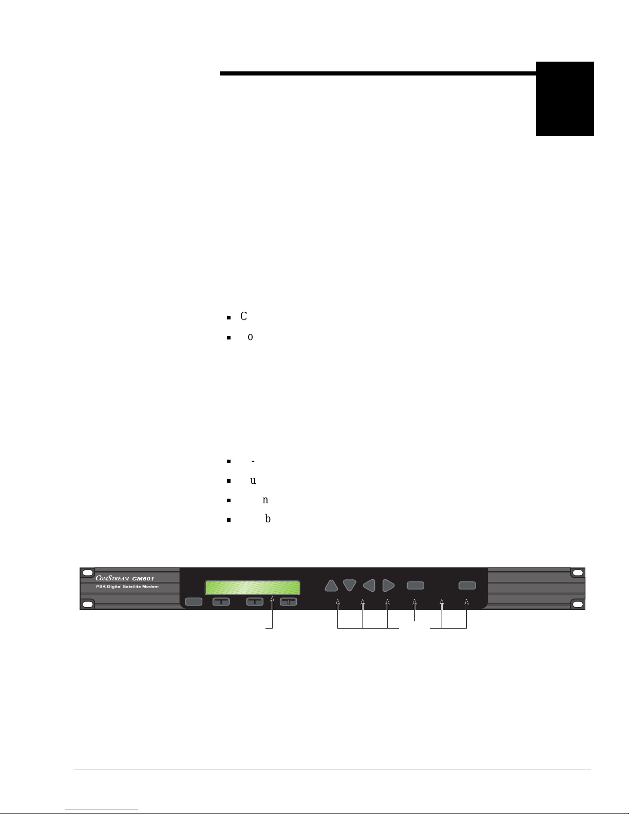
Front Panel Operation 6-1
6
Front Panel Operation
Every CM601 has an interactive front panel with push buttons, LED indicators,
and an LCD display allo wing the CM601 to be com pletely c onfi gured, mon itore d,
and controlled from the front panel.
The valuable front panel status and fault LEDs provide
at-a-glance
status
checking enabling you to quickly scan the front panel to check for any abnormal
operating conditi ons. This is especially useful for large earth station or rackmounted system applications.
This chapter describes the front panel:
Components
Commands, including command functions and valid parameters, navigating
through the command tree, as well as command syntax and entry
For informatio n on fault monitoring, logging, and conditions, refer to the chapter
on fault handling. For a detaile d description of an y command, refer to the CM601
Reference G u ide .
CM601 Front Panel
Components
The front panel, shown in Figure 6-1, provides access to various commands for
local control of the CM601. This panel cons ists of:
24-character LCD
Illuminated status a nd fault alert messages
Tx Enable dedicated push button with illum inated message
Push buttons below the LCD to select configuration, monitor, and fault
commands, and Previous, Modify, Cursor, and Enter selection buttons
Figure 6-1 CM601 Front Panel
Previous
Modify Cursor Enter Tx Enable
View Only Test Mode Rx Sync FAULT FAULT Tx Enabled
G734-01
LEDsLCD Display
Page 74

6-2 Front Panel Operation
LCD Display
The 24-character LCD displays the types of information described in Table 6-1.
Descriptions of the functional types of commands are listed in Table 6-2.
Table 6-1 LCD Display Information
Type Description
Messages Pro vides information such as modem ID, error messages, fault log
history, and so on.
If the command response is specific to a card in a duplicate-card
configuration, the slot number will precede the message.
The >> characters followi ng a message indicate a continuation of the
message, which can be viewed by pressing the right Cursor button.
Functional commands Categorizes commands into functional groups: configuration, monitor,
and fault.
Installed card Displayed in the format:
<slot>:<card>
For e xample,
1:RS449
indicates that slot #1 contains an RS-449
I/O card .
Command May be displayed in a group of commands, such as FaultLog-Current-
Clear, or in a list that can be scrolled, such as demodulator commands.
If the command has an associated parameter, both the command and
current value of the parameter are displayed in the format:
<command> <parameter>
If the command is specific to a card in a duplicate-card configuration,
the slot number will precede the command.
Navigation
More
indicates that there are additional options available on the current
level of the command tree.
Table 6-2 Command Functional T ypes
Function Description
Configuration In general, these commands have parameters that can be modified and entered
to change the operating characteristics of the CM601.
Included in this category are the commands that direct the CM601 to perform
real-time functions.
Configuration commands used when the optional BERT is enabled are referred
to as BERT Config (BConfig) commands.
Monitor Provide query (view-only) inform ation on the performance, operating
environment, and nonfault-related conditions of the CM601.
Monitor commands used when the optional BERT is enabled are r eferred to as
BERT Monitor (BMonitor) commands.
Fault Provide information on the functional status of the CM601; may indicate when
an external piece of equipment is not configured properly or is faulty.
Fault commands are query-only with the except ion of the Clear Fault Log (CF)
command.
Page 75

Front Panel Operation 6-3
LEDs
The CM601 front panel LED messages are described in Table 6-3. The LEDs are
located to the right of the LCD display. These LEDs indicate the status of certain
CM601 operating and hardware con ditions. Some are visible with or without
illumination; others are visible only when illuminated.
Table 6-3 CM601 LE Ds
LED Message Active Inactive Description
View Only
Yellow N ot
visible
Indicates that confi guration parameters ma y
not
be changed using t he front panel buttons. The
buttons can be used to scroll through and view the command lists.
Test Mode
Yellow N ot
visible
Illuminates as long as one or more of the CM601 test modes is active. F or ex ample, if any
LoopBack function, Pure Carrier, or Internal BERT is enabled and running, this message is
illuminated.
The purpose of this message is to provide a visible warning that the CM601 is not configured
for normal operation when a special test mode or test function is active. The message must
not
be visible for the CM601 to operate normally.
Rx Sync
Green White Illuminates when the entire receive signal and data path of the CM601 is synchronized to the
receive signal and valid data is being provided at the user data port. Receive synchronization
includes demodulator carrier sync, demodulator bit time sync, decoder sync (if operating with
Sequential or Viterbi decoding enabled), and receive path synchronization of any receive data
processing card installed in the CM601. For example, if an optional open network Framing Unit
is installed, it must have receive frame sync before the
Rx Sync
message can be
illuminated.
The
Rx Sync
message appears white if the CM601 is
not
synchronized to the receive
signal. This status message is not directly affected by any push buttons on the front panel.
Fault
Red Not
visible
Illuminates as long as a selected CM601 fault condition e xist s . You can select which CM601
fault conditions aff ect this indicator. Some users are concerned only with hardware fault
conditions that may indicate a bad card that must be replaced. Others are concerned with
operational f ault conditi ons and hardware f ault s; f or example, you ma y want to know when the
demodulator loses sync.
The red
Fault
message is associated with the CM601 current fault status register . This
fault register is 32 bits long, each bit representing one fault condition. Refer to the CM601
Reference Guide for a detailed description of the Current F ault Status (ST), Current Fault
Status Overlay Mask (STO), and View Current Status (VS) commands.
Fault
Yellow N ot
visible
Indicates that a selected CM601 fault has been logged. Once a fault is detected, it is
remembered
in the CM601 fault log, even if the fault disappears, until the fault register is
cleared. You can select which CM601 faults affect this indicator.
The yellow
Fault
message is associated with the CM601 fault log register. The fault log
register is 32 bits long, each bit representing one fault condition. Refer to the CM601
Reference Guide for a detailed description of the Fault Log History Query (FL), Fault Log
Overlay Mask (FLO), View Faults (VF) and View Faults with Time Stamp (VFT) commands.
The fault register is cleared by the Clear
fault register command accessed through the front
panel Faul ts, or the remote Clear Fault Log (CF) command. For information on the CF
command, refer to the CM601 Reference Guide.
Tx Enable
Green W hite Illuminates when the modulator output is enabled.
Page 76

6-4 Front Panel Operation
Buttons
CM601 commands are organized in a tree structure. Table 6-4 lists the buttons
used to navigate through the tree structure and to select and enter commands.
Table 6-4 CM601 Front Panel Buttons
Button Description
Previous Used to navigate from a lower level to a higher level in the command
tree.
Previous^< Used to access the front panel lockout command. This command
prohibits accidental or unauthorized modifications of the CM601
operating configurati on.
LCD
(left, center, and right)
Below the 24-character LCD are three but tons t hat have T-shaped icons
above them. They are used for selecting commands from the command
tree.
Modify
(up and down)
Used to scroll up and down through parameter lists for the command
currently displayed in the LCD.
Cursor
(left and right)
Used to:
Navigate among commands on the same level
Activate the cursor, represented by one or more flashing characters,
in the LCD display
Move the cursor through the parameter field within the LCD display
Enter Used to issue the command with the parameter that is currently
displayed.
Tx Enable Used to enable and disable modulator output. This button does not
aff ect the LCD display and is independent of all other buttons on the
front panel.
Page 77
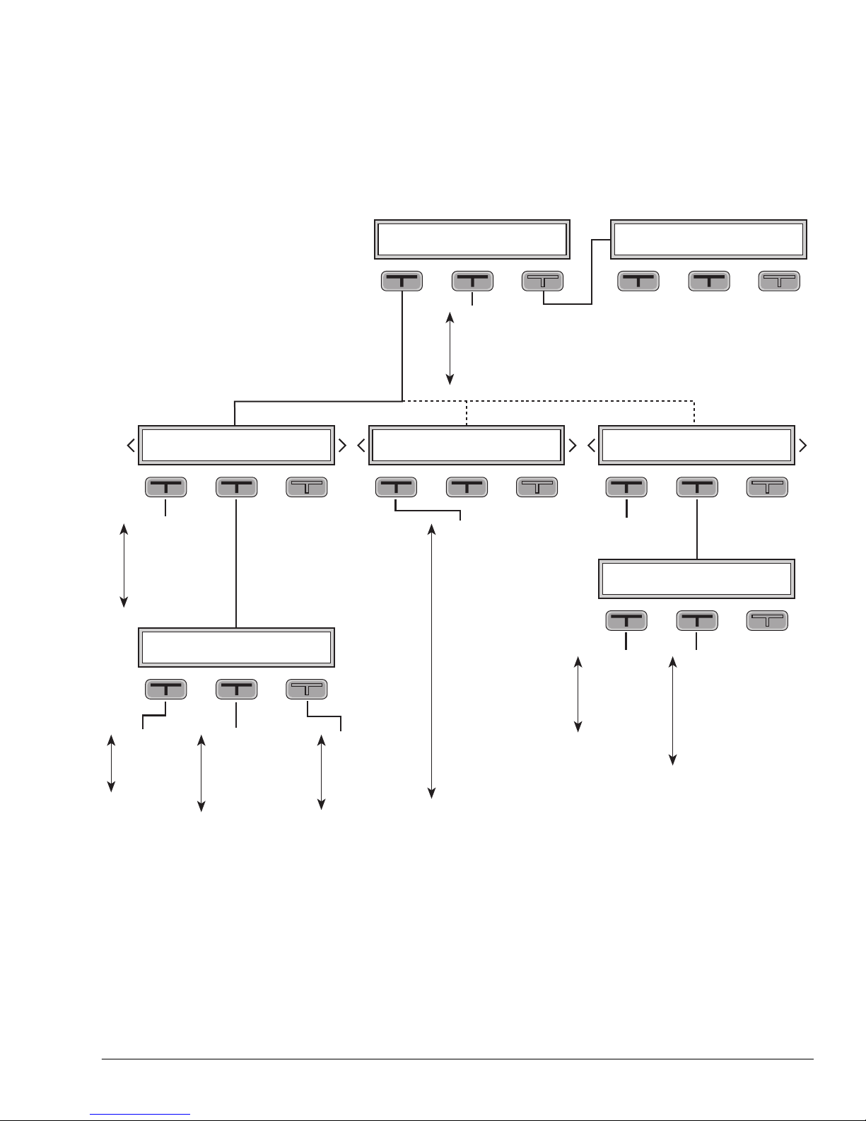
Front Panel Operation 6-5
CM601 Command Tree The front panel provides access to various commands for local control of the
CM601. These commands reflect the configuration of the CM601 and are
organized in a tree structure that is accessed using the front panel buttons. The
command t ree for a stan d ar d CM601, is shown in Figure 6-2.
Figure 6-2 CM 601 Front Panel Command Tree
Eb/No
Rx Offset
AGC Level
Chan Err Rate
Tx Clk
Buffer Fill Level
Rx Clk
UserTxData
UserRxData
Modem
LoopBack
Init Factory Default
Initialize New Firmware
Tx Active IO
Rx Active IO
TxDataRate
RxDataRate
Tx Freq
Rx Freq
TxSymRate
RxSymRate
Tx Code Rate
Rx Code Rate
Tx Mod Type
Rx Mod Type
Tx Diff Encoding
Rx Diff Decoding
Tx Filter Type
Rx Filter Type
Acquisition
Tx Pwr Level
Tx Pure Carrier
Modem Loopback
Buffer Mode
Buffer Delay
Buffer
Buffer Clk Sel
Tx Clock Source
Tx Scrambling
Rx Scrambling
No Commands Present
BERT Test Mode
BERT Control
BERT Error
BERT Pattern
BERT Usr Ptrn
BERT Blk Length
BERT SyncLvl
BERT Sync
BERT Sync History
BERT BitErr
BERT BitCnt
BERT AvgBER
BERT BlkBER
BERT BlkErr
BERT BlkCnt
BERT AvgBLER
BERT Data
Baud Rate
Remote Control
Remote Dat/Par
Protocol
Packet Address
1:〈card〉〈software ver.〉
2: " " "
3: " " "
4: " " "
5: " " "
6: " " "
7: " " "
:AA
Lamptest
Clock
Date Mo/Da/Yr
LCD Contrast
LCD Timeout
Self T est
G736-01
Config Monitor Faults
FaultLog Current Clear
4:Systm 4:M&C More 5:Modem More 1:RS449 1:BERT More
BConfig BMonitor
Remote S/W Ver Misc
ComStream CM601 ComStream CM601
ComStream CM601ComStream CM601 ComStream CM601
ComStream CM601
ComStream CM601
Page 78

6-6 Front Panel Operation
For example:
To navigate to 5:Modem from
Config Monitor Faults
, first press the
LCD button under
Config
. This displays
4:System 4:M&C More.
Select
More
. This displays
5:Modem More
.
Pressing the
Previo us
button from this displa y takes you one leve l
higher (up) in the command tree to
Config Monitor Faults.
Selecting
More
from
5:Modem More
displays slot 1’s option cards,
such as
1:RS232 1:BERT More
, if these option cards a re insta lled, or
System M&C More
if no option cards are installed in slot 1.
To navigate to System Loopback from
Config Monitor Faults,
select
Config
, then select
4:Systm
, then scroll through the options usin g
the down m odify button u ntil Loopback displays. To return to 4:Systm, press
Previous
.
A brief description of the func tion of each command tree level is provided in
Table 6-5.
Table 6-5 CM601 Front Panel Command Tree Levels
Level/Components Description
Config
Access to commands that determine CM601 operating characteristics or direct
the CM601 to perform specific real-time functions
4:Systm Macro, multi-card, and chassis configuration commands
4:M&C Access to monitor and control functions
Remote – commands associated with the remote control interface port
S/W Ver – access to software version number of each installed card in the
CM601
Misc – miscellaneous M&C functions such as terminal emulation and
system self-test
5:Modem Modulator, demodulator, and Doppler buffer commands
1:BERT Access to BERT configuration and monitor commands:
BConfig – configuration commands used to access, modify, and issue
BERT commands
BMonitor – commands used to review the status results of the BERT
Monitor
Commands that report performance and nonfault information provided by
various monitoring points located within the CM601
Faults
Commands that provide information on the status of the CM601 or indicate
when an external piece of equipment is improperly configured or is faulty
Faul tLog Provides historical account of all faults that occurred since the last time the
faults were cleared; associated with yellow fault LED. A displayed fault is
preceded by the slot number of the card that is generating the fault message.
Current Provides account of all faults present at any one point in time; associated with
red fault LED. A displayed fault is preceded by the slot number of the card that
is generating the fault message.
Clear Erases the contents of the fault log
Page 79

Front Panel Operation 6-7
Navigating Through the
Command Tree
Shortly after the CM601 is po w ered on, identification (ID) information appears on
the LCD. The default ID is
ComStream CM601
. At this time, pressing any of
the LCD buttons caus es Conf ig>Monitor >Faul ts to appear on the LCD. The LCD,
Cursor, and Modify b utt ons are use d to na vig ate through the front pane l command
tree.
Tree Level Navigation
To navigate between l evels of the com m and tree , perfo r m the following:
To move do wn to the level assoc iated with a displayed item, press the LCD
button directly below that item.
To move to the ne xt higher level, press the Previous b utton.
If More is displayed, access more sel ections at the same level by pressing the
LCD button below More, or press the Cursor buttons.
Command List Navigation
To navigate to commands associated with an installed car d or command group,
display the name of that card a nd press the LCD button below it. A command will
appear on the LCD wi th one of it s pa rameters. To scroll through the command list,
use one of the following methods:
Press the left or center LCD button. Each button press will scroll down one
command in the command list. When the bottom of the list is reached,
pressing the left or center LCD button will display the command at the top of
the list.
Use the Modify buttons to scroll up or do wn the command list.
Press the Previous button to return to the next highe r level.
Navigating Between Command Lists
If you access a command from a command list and then navigate to other
commands on that same level, when you return to the list, the last command
viewed will be displa yed. However, if you navigate to different levels and then
return to a previ ously viewed command list, the command at the top of that list
will be displayed. Following are some examples:
Example: Comparing Command Parameters on the Same Level
This example requires t he CM601 to be conf igur ed f or IF loop back opera tion wi th
the BERT enabled. To insert a bit erro r and verify that it is rece ived:
1. Navigate to BConfig>BMonitor.
2. Select BMonitor.
3. Scroll down the BMonitor command list to the BERT BitErr command and
note the number of errors.
4. Press the Previous button to return to BConfig>BMonitor.
Page 80

6-8 Front Panel Operation
5. Select BConfig.
6. Scroll to the BE RT Error comma nd.
7. Select Insert and press the Enter button.
8. Press the Previous button to return to BConfig>BMonitor.
9. Select BMonitor and verify that a bit error was received. It is not necessary to
scroll down the BMonitor command list.
Example: Comparing Command Parameters on Different Levels
This example is simila r to the previous one except that steps are added to check
the AGC level. Perform the following steps to insert a bit e rror, check the AGC
leve l, and verify that the bit error is rece ived:
1. Navigate to BConfig>BMonitor.
2. Select BMonitor.
3. Scroll down the BMonitor command list to the BERT BitErr command and
note the number of errors.
4. Press the Previous button to return to BConfig>BMonitor.
5. Select BConfig.
6. Scroll to the BE RT Error comma nd.
7. Select Insert and press the Enter button.
8. Press the Previous button three times to return to Config>M onitor>Faults.
9. Select Monitor.
10. Scroll down the Monitor command list to the A GC Level command and note
the value.
11. Pr ess the Previous button to return to Config>Monitor >Faults.
12. Navigate to BConfig>BMonitor.
13. Sel ect BMonitor . I n this e xample the first command in the BMonitor
command list is displayed.
14. Scroll down the BMonitor command list to the BERT BitErr command and
verify that a bit error was received.
Command Display
Configura tion commands can be viewed, entered, or modified using the LCD,
Cursor, Modify, and Enter buttons. Other remote commands that are not directly
accessible from a command tree list can be entered using the terminal emulator
(:AA) feature. Monitor and fault messages are view-only.
Page 81

Front Panel Operation 6-9
Issuing Commands
Through the Command
Tree
To issue a command from the front panel through the command tree:
1. Navigate to the desir ed command using the LCD, Cursor, and Modif y buttons.
2. Press the right LCD button or one of the Cursor buttons to select the
command. All or part of the command or its parameter will flash.
3. Change the parameter as needed. I f the para meter is one of a set of options,
scroll through the paramete r list by doing one of the following:
Press the right LCD butt on to scroll down the parameter list.
Use the Modify buttons to scroll up or do wn the parameter list.
If the parameter requires entry of a number:
a. If the numeric character that you want to change is not flashing, use the
Cursor buttons to make it flash.
b. Scroll through the list of numeric characters using the Modify buttons.
c. Repeat steps a and b as necessary until the entire parameter appears as
desired.
For numeric parameters suc h as frequency v alue s or transmit power le v el,
cursor location determines the amount the value is changed based on its
numeric position (ten s, hundr e ds, etc.) For example, assume the number
4957 is displayed. If the 9 in the hundreds’ digit position is flashing and
the up Modify button is presse d, the value of the parameter will increase
by one hundred and appear as 5057.
4. Issue the command by pressing the Enter button. An asterisk (*) will appear
briefly to the left of the command parameter and then disappear. The
command and its updated parameter will the n be displayed and will not flash.
If the Enter button is
not
pressed, the parameter will not be changed.
If no part of the command is flashing, pressing the Enter button will ha ve
no effect.
T o leave a command
without
modifying it, when an y pa rt of it i s f lashing, na vigate
to another command or level with the Previous, left or center LCD buttons.
Issuing Commands with
the Terminal Emulator
Commands not directly accessible from the command tree can be issued and
modified from the front panel using the terminal emulator :AA command. The
following remote command syntax is used when issuing commands using the
terminal emulator command:
<comma nd mn em on ic > <p ara me te r>
where:
<command mnemonic>
refers to a two- or three-letter remote command
abbrevia tion that replaces the AA on the display. For a duplicate-card
configura tion, the slot number replaces the initial blank space as follows:
<slot number>:<command mnemonic> <parameter>
There must be one space betwe en the command mnemoni c and the pa rameter;
this space is entered by pressing the → (right arrow) key .
<parameter>
refers to any value pertaining to the command. The
parameter for a query command is a question mark (?); some commands do
not require a param et er.
Page 82

6-10 Front Panel Operation
For example, to reduce the acquisition range from 30000 Hz to 10000 Hz, the
LCD will app ear as fo llows :
Initial display of :AA command
:AA
Use the terminal emulator function to type the remote syntax
AR 10000
Display after command is typed
:AR 10000
To issue a command using the terminal emulator:
1. Navigate to the terminal emulator :AA command using the LCD, Cursor, and
Modify buttons.
2. Press the right LCD button or the Cursor buttons to select the command.
3. Enter the command using terminal emulator syntax.
a. If the character that you want to change is not flashing, use the Cursor
buttons to make it f lash.
b. Scroll through the list of characters using the Modify buttons. The
characters display in the following order:
•Space
• ? (question mark)
• - (hyphen)
• , (comma)
• 0 through 9
• A through Z
c. Repeat steps a and b until the entire command appears as desired.
4. Issue the command by pressing the Enter button.
If the command was a query, the LCD will display the response for a few
seconds and then redisplay
:AA
.
If the command was successful ly executed, the LCD will redispl ay
:AA
.
If an error occurs, the LCD will display an error message for a few
seconds and then redisplay
:AA
.
Command Summary Table 6-6 lists the front pa nel commands for a standard CM601 with no installed
option cards. These commands are summariz ed in the order in which they appear
in the command tree, from top to bottom, and then left to right. Included are:
Leve l to which the front panel command is attached
Front panel command
Remote command equivalent and memory type
Command function
Either the parameters a vailable for the front panel command or the response
format for the monitor and status co mmands
This table is also prov ided as a quick reference card.
Page 83

Front Panel Operation 6-11
Table 6-6 Front Panel Command Summary
Command Remote/ Memory Function Front Panel Parameters or Response Format
C
ONFIG>SYSTM
UserTxData PTD (NV) Primary transmit data rate macro 4800 to 512000
UserRxData PRD (NV) Primary receive data rate macro 4800 to 512000
Modem RE (V) Reset CM601 RESET
LoopBack LB (V) Loopback test modes DISABLE, IF, NEAR, FAR
Init Fact ory Default IN (V) Initializ e factory default —
Initialize New Firmware I NF (V) Initialize new firmware (all config parameters are returned to defaul ts)
Tx Active IO TIO (NV) Transmit active IO 0, 1
Rx Active IO RIO (NV) Receive active IO 0, 1
C
ONFIG
>M&C>R
EMOTE
Baud Rate BR (NV) Remote baud rate 75, 300, 1200, 2400, 4800, 9600
Remote Control MEI (NV) Remote control electrical interface RS-232, RS-485
Remo te Da t/Par MDP (NV) Remo te p a r ity 8/NO NE, 7/ODD
Protocol MPT (NV) Remote protocol PACKET, ASCII
Packet Address MPA (NV) Packet address 1 to 31
C
ONFIG
>M&C>S/W V
ER
n:SWV SWV (NV) Display of software version by slotn = 1, 2, 3, 4, 5, 6, 7
C
ONFIG
>M&C>M
ISC
:AA — Terminal emulator allows commands to be issued and modified from
the front panel using use remote command syntax
Lamptest LMP (V) Lights front panel LEDs ON; returns LEDs to valid state after a few seconds
Clock TIM (NV) Real-time clock hh:mm:ss
Date Mo/Da/Yr DAY (NV) Real-time date mm/dd/yy (month/day/year)
LCD Contrast LCC (NV) Adjusts contrast on LCD 0 to 10; 0 is lightest setting, 10 is darkest setting
LCD Timeout LBT (NV) Automaticall y turns off LCD
backlight
0 to 20 minutes; 0 = always off, 20 = always on,
1-19 = minutes to timeout
Self-Test BIT (V) B uilt-in self-test EXECUTE
C
ONFIG>MODEM
TxDataRate TD (NV) Transmit data rate
n
where n=4800 to 512000 bps
RxDataRate RD (NV) Receive data rate
n
where n=4800 to 512000 bps
Tx Freq TS (NV) Transmit IF synth frequency
nnnnn.nnn
kHz
Rx Freq RS (NV) Receive IF frequency
nnnnn.nnn
kHz
TxSymRate TR (NV) Transmit symbol rate
n
where n=4800 to 512000 sps
RxSymRate RR (NV) Receive symbol rate
n
where n=4800 to 512000 sps
Tx Code Rate TC (NV) Transmit FEC coding Uncoded, Seq
1
/2
, Seq
3
/4
, Vit
1
/2
, Vit
3
/4
, Vit
7
/8
Page 84

6-12 Front Panel Operation
Rx Code Rate RC (NV) Receive coding rate Uncoded, Seq
1
/2
, Seq
3
/4
, Vit
1
/2
, Vit
3
/4
, Vit
7
/8
Tx Mod Type TM (NV) Transmit modulation type QPSK, BPSK
Rx Mod Type RM (NV) Receive modulation type Q PSK, BPSK
Tx Diff Encoding DM (NV) Transmit differential encoding O FF, ON (remote equivalent: 0, 2)
Rx Diff Decoding DD (NV) Diff er ential decoding OFF, ON (remote equivalent: 0, 2)
Tx Filter Type MFS (NV) Transmit filter mask ComStrm, IBS/IDR, SMS
Rx Filter Type DFS (NV) Receive filter mask ComStr m, IBS/IDR, SMS
Acquisition AQ (NV) Acquisition restart FAST, NORMAL, STOP
Tx Pwr Level TP (NV) Transmit IF power lev el -25.0 to -5.0 dBm
Tx Pure Carrier PC (V) Pure carrier test OFF, ON
Modem Loopback
MLB
(V) Modem card loopback mode DISABLE = disable; NEAR = near dat a; FAR = far
data
Buffer Mode DBM (NV) Doppler buffer mode Buffer = enable buffer; Bypass = enable bypass
Buffer Delay DB D (NV) Doppler buffer delay (in msec) 1 to 1000
Buffer DBR (V) Doppler buffer reset RESET
Buffer Clk Sel DCS (NV) Doppler clock select Ext (TT) = user-supplied transmit; Ext Conn = user-
supplied external; RT = demodulator derived; Int
(ST) = in te rn al
Tx Clock Source MB (NV) Transmit timing EXT, INT, LOOP
Tx Scrambling SM (NV) Transmit scrambling OFF, COMSTRM, IDR Man.
Rx Scrambling SD (NV) Demod descrambling OFF, COMSTRM, IDR Man.
C
ONFIG
>1:RS449
(no standard commands avail able; commands may appear depending upon installed I/O card)
C
ONFIG
>1:BERT>BC
ONFIG
BERT Test Mode BEN (V) B ERT enable ENABLE, DISABLE
BERT Control BRE (V) BERT reset and control START, STOP, RESET
BERT Error BEI (V) BERT error insert INSERT
BERT Patter n BPT (NV) BERT pattern type 2^9-1, USER, 1:1, MARK, SPACE
BERT Usr Ptrn B UP (NV) BERT user pattern 0 to 255
BERT Blk Length BBL (NV) BERT bloc k length 10^8, 10^7, 10^6, 10^5, 1 sec
BERT SyncLvl BST (NV) BERT synch threshold 1000/10^4, 2500/10^4
Table 6-6 Front Panel Command Summary
Command Remote/ Memory Function Front Panel Parameters or Response Format
Page 85

Front Panel Operation 6-13
C
ONFIG
>BERT>BM
ONITOR
Return Format
BERT Sync BSS BERT synchronization status In Sync, Out of Sync
BERT Sync History BSF BERT sync history LOSS, OK
BERT BitErr BEC B ER T Bi t Error Count nnnnn
BERT BitCnt BBC BERT bit count nnnnn
BERT A v gBER BER BERT average BER
n n
10^-y
BERT BlkBER BBE BERT block BER
n n
10^-y
BERT BlkErr BWE BERT bloc k error count nnn
BERT BlkCnt BLC BERT bloc k count nnn
BERT A v gBLER BLE BERT average bloc k error rate
n n
10^-y
BERT Data BDI BERT Data Inverted Inverted, Not Inverted
M
ONITOR
Eb/N
0
EB Estimated Eb/N0 query
nn.n
dB
Rx Offset RO Receive IF offset query nnnn
AGC Level AG AGC level query
ny
where n x 10^-4
Chan Err Rate CE Channel er ror rate query
nnn
Hz
Tx Clk TT Transmit clock frequency query
n.nnn
kHz
Buff er Fi ll Level DFL
Doppler buffer fill level
query response: 1 (empty) to 99 (full)
Rx Clk RTF Receive clock frequency query
n.nnn
kHz
F
AULTS
Faults>Faul tLog FL Fault log query displays list of modem faults
Fault>Current ST Current fault status displays current modem status
Fault>Clear CF (V) Clear fault —
B
UTTONS
Tx Enable E M (V) Modulator TxIF output enabled (green, illuminated); disabled (white)
Previous^> FPL (NV) Front panel lockout normal/view-only/lock out front panel access
Note: n and y indicate numeric characters
Parameters are listed here as they appear on the LCD. The carat symbol represents superscript, as it is not an available option on the LCD.
Table 6-6 Front Panel Command Summary
Command Remote/ Memory Function Front Panel Parameters or Response Format
Page 86

6-14 Front Panel Operation
C
OMSTREAM
A Spar Company
®
Page 87
Configuration Examples 7-1
7
Configuration Examples
Overview This chapter prese nts examples of the most common CM601 configurations.
These examples are the foundation of basic CM601 configurations and can be
changed and expanded to meet your individual system needs. The following
configurations are used in the examples:
ComStream closed-networ k-compatible operation with a stand ard CM601
card set
ComStream closed-networ k-compatible operation with a CM601
configura tion consisting of two data interface cards
ComStream open-network- compatib le operat ion with a CM601 configura tion
Each example consists of a set of conf iguration commands which are issued
through a remote terminal.
Additional examples of configurations with various option cards may be found in
the CM601 option card manuals.
Page 88

7-2 Configuration Examples
ComStream Closed-
Network-Compatible
Operation
T wo closed- network-c ompatible operation e xamples are provided. One exa mple is
based on a standard CM601 confi guration, while the other is based on a CM601
that has two installed interface cards.
CM601 Configuration with Standard Cards
This configuration consists of:
Standard CM601 modem with the following cards:
M&C
Modem car d
No option cards
User data rate is 64 kbps
QPSK
Sequential rate 1/2 decoding
Transmit timing
Provided by modem on ST line
DTE is returning a buffered version of ST on the TT line
Filtering is ComStream closed-network
The IF frequencies used in this exa m ple are representative only. You must
calculate the actual I F frequencies based on the RF equipment used and the
frequencies assigne d by the satellit e provide r prior to any actual RF transmissions .
To config ure the system:
1. Ensure that the Test Mode LED on the front panel is not ill uminated. If it is
illuminated, perform the following steps :
a. Turn all loopbacks off, enter
LB 0
.
b. Turn pure carrier mode off, enter
PC 0
.
c. If an internal BER T is installed, turn it off, enter
BEN 0
.
2. Configur e the modem for the timing mode. For this example:
a. Set the modulator to provide transmit timing, enter
MB 2
.
b. Set the modulator to latch transmit data on the falling edge of the TT
clock, enter
ML 0
.
3. Select ComStream closed-network filte ring on the modulator and
demodulator, enter
MFS 0
and
DFS 0
.
Page 89

Configuration Examples 7-3
4. Disable or enable modulator a nd demodulator spectral inversion, enter:
MI 0
and
DI 0 or MI 1
and
DI 1
resp e ctively
5. Select ComStream scrambling and descrambling, enter
SM 1
and
SD 1
.
6. Enable dif ferential encoding and decoding, enter
DM 1
and
DD 1
.
7. Select QPSK modulation and demodulation, enter
TM 1
and
RM 1
.
8. Set the transmit IF frequency to 82 M H z, ent er
TS 82000
9. Set the receive IF frequency to 82 MHz, enter
RS 82000
10. Select Sequential rate 1/2 for encoding, enter
TC 1
.
11. Select Sequential rate 1/2 for decoding, enter
RC 1
.
12. Select a user transmit data rate of 64000 bps, enter
PTD 64000
.
13. Check the transm it symbol rate by issuing a transmit symbo l rate query
command
TR ?
which should return a val ue of 64000 sps.
14. Select a user receive data rate of 64000 bps, enter
PRD 64000
.
15. Check the receive symb ol rate by issuing a receive symbol rate query
command
RR ?
which should return a val ue of 64000 sps.
16. Set the transmit power level of -15 dBm, enter
TP 150
.
The modem is ready to pass data over the sate llite. It should acquire almost
immediately. If it does not acquire:
1. Ensure that acquisition (AQ) is enabled. If it is not, reset the demodulat or’s
acquisition process, enter
AQ 1
.
2. Test the equipment using the b uilt-in BERT feature, if it is available. Issue a
BEN 1
command or use an external BERT. For more information on the
BERT, refe r to the ap pro pri at e app endix.
Page 90

7-4 Configuration Examples
CM601 Configuration with Two Data Interfaces
This configuration consists of:
Standard CM601 with the follo wing cards:
M&C
Modem car d
I/O in slot 1
User data rate is 9.6 kbps
BPSK
Sequential rate 1/2 decoding
Transmit timing
Provided by the DTE
Trans mit clock and data sent to the I/O card in slot 1will be used for the
transmit portion
Receiv e data will be output from the I/O port on the modem card in slot 5.
Filtering is ComStream closed-network
The IF frequencies used in this exa m ple are representative only. You must
calculate the actual I F frequencies based on the RF equipment used and the
frequencies assigne d by the satellite provider prior to any actual RF transmiss ions
To config ure the system:
1. Ensure that the Test Mode LED on the front panel is not ill uminated. If it is
illuminated, perform the following steps :
a. Turn all loopbacks off, enter
LB 0
.
b. Turn pure carrier mode off, enter
PC 0
.
c. Turn the internal BERT off for each I/O ca rd and the modem card. This is
done by preceding the command with the slot number followed by a
colon:
• Enter
1:BEN 0
.
• Enter
5:BEN 0
.
2. Configur e the modem for the described I/O selection and timing mode noted
in the assumptions:
a. Select the I/O card in slot 1for TD and TT (if not data rate restrict ed),
enter
TIO 1
.
b. Select the modem card in slot 5 for RD and RT, enter
RIO 0
.
c. Select DTE to provide transmit timing, enter
MB 1
.
The modulator latches data on the falling edge of the TT clock when MB
is set to 1, and the state of the ML command will be ignored.
Page 91

Configuration Examples 7-5
3. Select ComStream closed-network filte ring on the modulator and
demodulator, enter
MFS 0
and
DFS 0
.
4. Disable or enable modulator a nd demodulator spectral inversion, enter
MI 0
and
DI 0 or MI 1
and
DI 1
respectively
5. Select ComStream scrambling and descrambling, enter
SM 1
and
SD 1
.
6. Enable dif ferential encoding and decoding, enter
DM 1
and
DD 1
.
7. Select BPSK modulation and demodulation, enter
TM 0
and
RM 0
.
8. Set the transmit IF frequency to 65 M H z, ent er
TS 65000
.
9. Set the receive IF frequency to 65 MHz, enter
RS 65000
.
10. Select Sequential rate 1/2 for encoding, enter
TC 1
.
11. Select Sequential rate 1/2 for decoding, enter
RC 1
.
12. Select a user transmit data rate of 9600 bps, enter
PTD 9600
.
13. Check the transm it symbol rate by issuing a transmit symbo l rate query
command
TR ?
which should return a val ue of 19200 sps.
14. Select a user receive data rate of 9600 bps, enter
PRD 9600
.
15. Check the receive symb ol rate by issuing the receive symbol rate query
command
RR ?
which should return a val ue of 19200 sps.
The modem is ready to pass data over the sate llite. It should acquire almost
immediately. If it does not acquire:
1. Ensure that the acquisition offset (AO) is set to 0.
2. Ensure that acquisition (AQ) is enabled. If it is not, reset the demodulat or’s
acquisition process, enter
AQ 1
.
3. Test the equipment using the b uilt-in BERT feature if available or an external
BERT.
Page 92

7-6 Configuration Examples
INTELSAT Business
Services (IBS)
Compatible Operation
In this example, the CM601 is configured with the standard CM601 card set and
an external Framing Unit, operating IBS serial at 384000 bps. This
IBS-compatible syst em consists of:
Standard CM601 modem with the following cards:
M&C
Modem car d
No option cards
Modem data rate is 409600 bps
QPSK
V iterbi rate 3/4 encoding and decoding
DTE is providing transmi t timing
Filtering is IBS/IDR open network
In addition, a simple IF loopback will be performed.
To config ure the system, perform the follo wing steps:
1. Ensure that the Test Mode LED on the front panel is not ill uminated. If it is
illuminated, perform the following steps :
a. Turn all loopbacks off, enter
LB 0
.
b. Turn pure carrier mode off, enter
PC 0
.
c. Turn the interna l BERT off, enter
BEN 0
.
2. Configur e the modem for the timing mode noted in the assumptions, select
DTE to provide transmit tim ing, enter
MB 1
.
Once the configuration parameters in steps 3 through 7 are set, they usually are
not changed.
3. Select IBS/IDR open network filtering on the modulat or and demodula tor,
enter
MFS 1
and
DFS 1
.
4. Disable modulator and demodulator spectral in version, enter
MI 0
and
DI 0
.
5. Disable ComStream scrambling and descrambling. IBS scrambling and
descrambling should be sele ct ed in the external Framing Unit. Enter
SM 0
and
SD 0
.
6. Enable dif ferential encoding and decoding, enter
DM 1
and
DD 1
.
7. Select QPSK modulation and demodulation, enter
TM 1
and
RM 1
.
8. Set the transmit IF frequency to 70,000 kHz, enter
TS 70000
.
9. Set the receive IF frequency to 70,000 kHz, enter
RS 70000
.
10. Sel ect r ate 3/4 Vite rbi encoding, enter
TC 4
.
Page 93

Configuration Examples 7-7
11. Sel ect rate 3/4 V iterbi decoding, enter
RC 4
.
12. Sel ect a transmit data rate of 409600 bps, enter
PTD 409600
.
This assumes an IBS serial Framing Unit operating with a terrestrial data rate
of 384000 bps. The transmit data rate wa s calculated as (384000 * 16)/15.
13. Check the transm it data rate by issuing a t ransmit symb ol rate quer y command
TR ?
which should return a val ue of
273067 sp s
.
14. Sel ect a receive data rate of 409600 bps, enter
PRD 409600
.
This assumes an IBS serial Framing Unit operating with a terrestrial data rate
of 384000 bps. The receive data rate was calculated as (384 000 * 16)/15.
15. Check t he recei ve data r ate b y issuing the receive symbol rate que ry command
RR ?
which should return a val ue of
273067 sp s
.
Perform an IF Loopback
To perform an IF loopback, connect an IF cable between the Tx IF and Rx IF
connectors. The modem should acquir e almost immediatel y. If it does not acquire,
perform the following steps:
1. Issue an
EM 1
command to enable the modulator. When a modem is
factory-shipped, AE is set to one; therefore, EM should be set to one. If AE is
zero, ensure that the zero parameter is correct and determine the correct
setting for EM. For additional AE command information, refer to the chapter
on command descriptions.
2. Ensure that acquisition (AQ) is enabled. If it is not, reset the demodulat or's
acquisition process, enter
AQ 1
.
3. Test the equipment using the b uilt-in BERT feature if available. Issue a
BEN 1
command.
Enabling the BERT will take the external Framing Unit out of the loop.
The BERT ne eds the TT clock to operate while the modem is in external timing
(MB 1).
Page 94

7-8 Configuration Examples
Intermed i ate Data Rate
(IDR)-Compatible
Operation
In this e xample t he CM601 is conf ig ured with t he sta ndard CM601 card set and a n
external Frami ng Unit, operating in IDR mode at 1544000 bps. This IDRcompatible system consists of:
Standard CM601 modem with the following cards:
M&C
Modem car d
No option cards
Modem data rate is 1640000 bps
QPSK
V iterbi rate 1/2 encoding and decoding
DTE, or external Framing Unit, is providing transmit timing
Filtering is IBS/IDR open network
In addition, a simple IF loopback will be performed.
T o configure the system, perform the following steps:
1. Ensure that the Test Mode LED on the front panel is not ill uminated. If it is
illuminated, issue the following commands:
Turn a ll loopbacks off, enter
LB 0
Turn pure carrier mode off, enter
PC 0
Turn internal BERT off, enter
BEN 0
2. Configur e the modem for the timing mode noted in the assumptions:
Select the DTE, or external Fra ming Unit, to provide transmit timing,
enter
MB 1
.
Once the configuration parameters in steps 3 through 7 are set, they usually are
not changed.
3. Select IBS/IDR open network filtering on the modulat or and demodula tor,
enter
MFS 1
and
DFS 1
.
4. Disable modulator a nd demodulator spectr al inversion, enter
MI 0
and
DI
0
.
5. Select IDR-compatible scrambling and descrambling. It is assumed that the
external Framing Unit does not have this capability. Enter
SM 2
and
SD 2
.
6. Enable dif ferential encoding and decoding, enter
DM 1
and
DD 1
.
7. Select QPSK modulation and demodulation, enter
TM 1
and
RM 1
.
8. Set the transmit IF frequency to 70,000 kHz, enter
TS 70000
.
9. Set the receive IF frequency to 70,000 kHz, enter
RS 70000
.
10. Sel ect r ate 1/2 Vite rbi encoding, enter
TC 3
.
11. Sel ect r ate 1/2 Vite rbi decoding, enter
RC 3
.
Page 95

Configuration Examples 7-9
12. Select a modem transmit data rate of 1,640,000 bps, enter
PTD 1640000
.
This assumes an IDR Framing Unit operating with a terrestrial data rate of
1,544,000 bps. The transmit data rate was calculated as 1544000 + 96000.
Check the tra nsmit data rate by issuing a t ransmit symb ol rate que ry command
TR ?
which should return a val ue of
1640000
sps.
13. Sel ect a receive data rate of 1,640,000 bps, enter
PRD 1640000
.
This assumes an IDR Framing Unit operating with a terrestrial data rate of
1,544,000 bps. The receive data rate was calculated as 1544000 + 96000.
Check the recei ve d ata rate b y issuing t he receive symbol rate query command
RR ?
which should return a val ue of
1640000
sps.
Perform an IF Loopback
To perform an IF loopback, connect an IF cable between the Tx IF and Rx IF
connectors. The modem should acquir e almost immediatel y. If it does not acquire,
perform the following steps:
1. Issue an
EM 1
command to enable the modulator. When a modem is
factory-shipped, AE is set to one; therefore, EM should be set to one. If AE is
zero, ensure that the zero parameter is correct and determine the correct
setting for EM. For additional AE command information, refer to the chapter
on command descriptions.
2. Ensure that acquisition (AQ) is enabled. If it is not, reset the demodulat or's
acquisition process, enter
AQ 1
.
3. Test the equipment using the b uilt-in BERT feature, if av ailable:
a. Place the modem in internal time, enter
MB 2
.
b. Issue a
BEN 1
command.
Enabling the BERT will take the external Framing Unit out of the loop.
Page 96

7-10 Configuration Examples
C
OMSTREAM
A Spar Company
®
Page 97
Fault Handlin g, Troubleshooting, and M aintenance 8-1
8
Faul t Handling,
Troubleshooting, and
Maintenance
This chapter includes the following information:
Handling, reporting, and logging of faults
Querying faults
Listing of standard fa ults
Interpreting f ault logs
Using fault overlay masks
Trouble shooting CM601 problems
Performing specification, system v a lidation, fault iso lat ion, and board-level
hardware tests
Specifying a data interface card when the CM601 is configured with an
optional I/O card
Upgrading software
Installing and remo ving option cards
Performing general CM601 maintenance
Fault Handling The CM601 continually chec ks for internal hardware fau lts, that may require card
replacement, and for operational or fault conditions that may require a change in
parameters or system configuration. CM601 commands can be used to:
Establish the fau lt conditions that will be monitored and reported by the rear
panel status relay conne ctor
Determine the manner in which external fault conditions are interpreted
Define the condi tions under which f ault mes sages are di splaye d on the remote
terminal or front panel
Clear the fault log, thereby resetting fault log register bits to nonf ault
conditions
Query the CM601 for its current fault status
View the faults that have been logged since the last CF command was issued
Page 98

8-2 Fault Handling, Troubleshooting, and Maintenance
Fault Reporting You, the operator, set the faults that are to be monitor ed and reported, as well as
the conditions under which faul t message s appear. Once set, these fault conditions
are monitored and reported by the rear panel status relay connect or and thei r
corresponding fa ult messages are displayed on a remote terminal or front panel.
Specifying Faults to be Monitored and Reported
Three commands are used to specify which faults will be monitored and reported:
Current Fault Ov erlay Mask (FO) — specifies the fault conditions that are to
be monitored and repor ted by the rear panel sta tus r elay. The FO parameter is
set to the sum of the bit weights of the selected faults.
Fault Relay Sense (FR) — specifies whether a current fault condition is
reported on the status rel ay as a contact be tween the normally closed or
normally open contact pairs of the For m C status relay.
Fault conditions include not only user-spe cified fault conditions set with the
FO command, but also power failure, power switch turned off, and unplugged
unit faults.
Fault Relay Sense External Signal Polarity (FRX) — specifies how the
CM601 will interpret the external faults that are monitored by the relay sense
pins. The FRX parameter define s whether a fault condition is a closed relay
contact or an open relay contact for each of the three relay sense pins.
Conditions for Remote Fault Messages
If a fault conditio n is detec ted by the CM601, an unsolicited fault message is
displayed on the remote terminal
only
for systems using ASCII remote protocol.
Depending upon the AL setting, an unsolicited ST 0 message may also appear
when the fault no longer exists. The AL command is used to enable or disable
fault reporting and to prevent unsolicited fault messages from being issued to the
remote terminal.
For example, assume that the receive signal has become too weak to detect.
If AL = 0 or 3, a query would have to be issued to disco ver the fault.
If AL = 1, the CM601 would automatically display several demodulator fault
messages on the remote terminal.
Now assume that the demodula tor gains sync.
If AL = 0 or 1, an unsolicited
ST 0
would appear on the remote terminal.
If AL = 3, a query w ould h av e to be issued to disco v er that the f ault s no longer
exist.
Page 99

Fault Handlin g, Troubleshooting, and M aintenance 8-3
Front Panel Fault LEDs
The CM601 has two fault message LEDs on the front panel. One illuminates
yellow and the othe r illuminates red. To specify which faults will cause these
LEDs to illuminate, use the following commands:
Fault Log Overlay Mask (FLO) — specifies which fault log conditions will
cause the yellow f ault LED to illuminate.
Current Fault Status Overlay Mask (STO) — specifies which fault conditions
will cause the red fault LED to illuminate.
The FLO and STO command parameters should be set to the sum of the bit
weights of the selected fa ults.
Fault Logging Once a fault is detected by the CM601, it is reported and stored in both a 32-bit
status register and a 32-bit fault log register. The bits found in either register are
identical, with each bit as signed to a specific fault. The status and fault registers
differ in that the:
Status regis ter only retains faults that are currently occurring
Fault log register retains faults until they are cleared with the remot e CF or
front panel Clear command
Each fault message is issued only once; subsequent occurrences of that f a ult will
not
cause fault messages to appear until the fault log register is cl ear ed.
At power- up or reset, all fault log register bits are set to fault conditions and must
be cleared with a CF command before faults can be succe ssfully monitored. The
first 10 fa ults in the fault history log are recorded with a date and time stamp and
are saved in volatile memory for subsequent viewing.
Fault Queries The status of the CM601 can be quickly determined by checking the front panel
LEDs. If any fault LEDs are illuminated, the current faul t status and fault log
register s can be queried, from eit her the remot e terminal or front pa nel, for further
fault information. Current fault status queries provide real-tim e reporting of
CM601 fault conditions present only at the time of the que ry . P rior conditions are
not
included. To determine the current CM601 fault status, use the following
commands:
The Current Fa ult Status query (ST ?) — this remote command displays
decimal number that repres ent s the contents of the bit-mapped current fault
status register for the CM601. The decimal number must be converted to
binary, the binary 1’s must be located, and, f inally, the bit locations of the
binary 1’s must be matched with the corresponding f ault condition.
The View Status query (VS ?) — this remote command displays a deta ile d
fault list for each installed card followed by the active fault conditions. The
list includes the name of the card, slot location, and descriptions of the fa ults.
Current Faults — this front panel command displays the current (real-time)
status of the CM601. If there are no fault conditions,
Modem Status OK
is displayed. If there are faults, they are displayed in a scrollable list. After 10
seconds of ina ctivity on the front panel push buttons, the LCD will update the
list with any ne w faults and automatically return to the top of the list.
Page 100

8-4 Fault Handling, Troubleshooting, and Maintenance
The fault log, which is a historical record of CM601 fault conditions, can be
queried using the following commands:
Fault Log query (FL ?) — th is rem o te command returns a deci ma l nu mb er
representing the bit-mapped fault log register. The decimal number must be
converted to binary, the binary 1s must be located, and, finally, the bit
locations of the binary 1s must be matched with the corresponding faults.
V iew Faults query (VF ?) — this remote command displays a complete card
listing that includes the name of the card, slot location, a nd descriptions of a ll
faults that ha ve occurred since the fa ults were last cleared.
V iew Faults with Time Stamp query (VFT ?) — this remote command
displays a list of
only
the first 10 faults that occurred since the fault log
register was cleared. The list includes fault de scriptions with date and time
stamps. The information is saved in volatile memory for subsequent viewi ng.
This feature is very he lpf ul when tracking infrequent system probl ems,
especially those tha t occur at unmanned sites.
Fault Log — this front panel command displays the fault log. If there are no
fault conditions,
Modem FaultLog is Clear
is displayed. If there are
faults, they are displayed in a scrollable list.
Standard CM601 Faults CM601 faults are listed in Table 8-1 by fault log register bit. Included for each
faul t is th e:
Fault log register bit
We ight
Displayed fault message
Type of fault, either:
Hardware (H) – caused by a circuitry failure in the CM601; usually
requires diagnosis and replacement of a faulty card
Operational (O) – indicat es real or potential problem in the
communications path; requires search for an abnormal operating
condition and action as appropr iate
Description of the fault
Possible causes of the fault
 Loading...