

Page 1
Odyssey 2000
Mobile Radio Instruction Manual
The 800MHz DC/MA Mobile Radio including
Direct Frequency Assignment (DFA) with
Digital LTR® Trunking
575-0000-0001
DC/MA is a registered trademark of ComSpace Corporation and LTR is a registered trademark of E. F. Johnson
Page 2

Instruction Manual Page 2 of 25
Table of Contents
TABLE OF CONTENTS....................................................................................................................................2
INTRODUCTION ...............................................................................................................................................4
ONE OR MORE OF THE FOLLOWING STATEMENTS MAY BE APPLICABLE:..............................5
NOTICES TO THE USER.................................................................................................................................5
SAFETY:...............................................................................................................................................................6
PRECAUTIONS ..................................................................................................................................................7
ODYSSEY SERIES MODEL 2000-800 SPECIFICATIONS...................................................................8
GENERAL............................................................................................................................................................8
RECEIVER...........................................................................................................................................................9
UNPACKING AND CHECKING EQUIPMENT........................................................................................10
PREPARATION................................................................................................................................................11
TOOLS REQUIRED.......................................................................................................................................11
POWER CABLE CONNECTION.................................................................................................................11
INSTALLING THE TRANSCEIVER...........................................................................................................12
ANTENNA MOUNTING......................................................................................................................................13
CONTROLS AND CONNECTIONS.............................................................................................................14
FRONT PANEL ..............................................................................................................................................14
PUSH BUTTON FUNCTIONS ..............................................................................................................................15
MICROPHONE....................................................................................................................................................16
DISPLAY.........................................................................................................................................................16
REAR PANEL CONNECTORS....................................................................................................................16
POWER INPUT CONNECTOR PIN-OUT ..............................................................................................................16
ACCESSORY CONNECTOR PIN-OUT..............................................................................................................17
BASIC OPERATIONS .....................................................................................................................................18
OPERATING FEATURES.....................................................................................................................................18
TRANSCEIVER FEATURES .................................................................................................................................18
TRUNKED SYSTEM FEATURES .........................................................................................................................18
SYSTEM KEY ....................................................................................................................................................19
GROUP SOFT KEY .............................................................................................................................................19
VOLUME SOFT KEY ..........................................................................................................................................19
VOLUME SPECIFICATIONS................................................................................................................................20
SCAN SOFT KEY................................................................................................................................................20
MENU AND SELECT SOFT KEY.........................................................................................................................20
TONE INFORMATION: .......................................................................................................................................22
ALERT TONE DEFINITIONS...............................................................................................................................22
GENERIC TONES ...............................................................................................................................................22
SPECIFIC TONES:..............................................................................................................................................23
TRUNKED OPERATION................................................................................................................................24
PLACING A DISPATCH CALL............................................................................................................................24
Page 3

Instruction Manual Page 3 of 25
RECEIVING A DISPATCH CALL.........................................................................................................................24
CONVENTIONAL OPERATION..................................................................................................................25
TRANSMITTING.................................................................................................................................................25
RECEIVING........................................................................................................................................................25
Page 4

Instruction Manual Page 4 of 25
Introduction
This Manual covers the Odyssey 2000 800MHz Mobile Radio for Digital
Channel/Multicarrier Architecture, DCMA, with Trunking. The unit is a compact twoway radio transceiver featuring digital technology developed by ComSpace
Corporation, that greatly increases the traffic carrying capabilities of the radio network
while at the same time improving the quality of communications. The principle features
are:
1) Digital Modulation with DCMA technology.
2) Digital Trunking (Direct Frequency Assignment) compatible with E.F. Johnson LTR
network protocols.
3) Enhanced voice quality via AMBE+ vocoder.
THANK YOU!
We believe that this “Technology development for the wireless future” will be an easy-touse transceiver that will provide dependable communications to allow peak operating
efficiency. We are grateful you chose ComSpace Corporation for your professional
mobile radio applications and believe that you will be pleased with the quality and
features of our products.
Page 5
Instruction Manual Page 5 of 25
ONE OR MORE OF THE FOLLOWING STATEMENTS MAY BE APPLICABLE:
FCC WARNING
This equipment generates or uses radio frequency energy. Changes or modifications to
this equipment may cause harmful interference unless the modifications are expressly
approved in the Operator’s Manual. The user could lose the authority to operate this
equipment if an unauthorized change or modification is made.
INFORMATION TO DIGITAL DEVICE USER REQUIRED BY THE FCC
This equipment has been tested and found to comply with the limits for a Class B digital
device, pursuant to Part 15 of the FCC Rules. These limits are designed to provide
reasonable protection against harmful interference in a residential installation.
This equipment generates, uses and can generate radio frequency energy and, if not
installed and used in accordance with the instructions, may cause harmful interference to
radio communications. However, there is no guarantee that the interference will not
occur in a particular installation. If this equipment does cause harmful interference to
radio or television reception, which can be determined by turning the equipment off and
on, the user is encouraged to try to correct the interference by one or more of the
following measures:
• Reorient or relocate the receiving antenna.
• Increase the separation between the equipment and receiver.
• Connect the equipment to an outlet on a circuit breaker different from that to which
the receiver is connected.
• Consult the dealer for technical assistance.
• GOVERNMENT LAW PROHIBITS THE OPERATION OF UNLICENSED
RADIO TRANSMITTERS WITHIN THE TERRITORIES UNDER
GOVERNMENT CONTROL.
• ILLEGAL OPERATION IS PUNISHABLE BY FINE OR IMPRISONMENT
OR BOTH.
• REFER SERVICE TO QUALIFIED TECHNICIANS ONLY.
NOTICES TO THE USER
Page 6

Instruction Manual Page 6 of 25
SAFETY:
It is important that the operator is aware of, and understands, hazards common to the
operation of any transceiver.
WARNINGS (INJURY FROM RADIO FREQUENCY TRANSMISSIONS):
• DO NOT OPERATE the mobile radio when someone outside the vehicle is within
15 inches (39 cms) of the antenna. For example, DO NOT OPERATE the mobile
transceiver when someone is either touching the antenna or in proximity as specified
above to avoid the possibility of radio frequency burns or related physical injury.
• This radio is NOT approved for use by the general population in an uncontrolled
environment. This radio is restricted to occupational use, work related operations
only where the radio operator must have the knowledge to control the exposure
conditions of passengers and bystanders by maintaining the minimum separation
distance of 15 inches (39 cms).
• The mobile must be used in vehicle-mount configurations with a maximum operating
duty cycle not exceeding 50%.
• Failure to observe the above warnings will result in exceeding the FCC RF exposure
limits.
• EXPLOSIVE ATMOSPHERES (GASES, DUST, FUMES, etc.): Turn OFF your
transceiver while taking on fuel or while parked in gasoline service stations. Do not
carry spare fuel containers in the trunk or your vehicle if your transceiver is mounted
in the trunk area.
• DYNAMITE BLASTING CAPS: Operating the transceiver within 500 feet of
dynamite blasting caps may cause them to explode. Turn OFF your transceiver when
in an area where blasting is in progress, or where “TURN OFF TWO-WAY RADIO”
signs have been posted. If you are transporting blasting caps in your vehicle, make
sure they are carried in a closed metal box with a padded interior. Do not transmit
while the caps are being placed into or removed from the container.
ANTENNA AND INSTALLATION CONSIDERATIONS:
• All equipment must be properly installed in accordance with ComSpace installation
instructions.
• To assure compliance with United Stated FCC regulations on RF exposure, the user
of the equipment must position the antenna in such a way to maintain a separation of
at least 15 inches (39 cms) between the antenna and the body of any user or nearby
person. For example, for rear deck trunk and window installations, the antenna must
be located at least 15 inches (39 cms) away from passengers and any bystanders.
• Ensure that the antenna is properly installed external to the vehicle and in accordance
with the requirements of the antenna manufacturer/supplier.
• Use only the supplied or an approved antenna. Unauthorized antennas, modifications,
or attachments could impair call quality, damage the equipment, or result in violation
of the ICNRP or the FCC.
Page 7

Instruction Manual Page 7 of 25
PRECAUTIONS
CAUTION:
Please observe the following precautions to prevent personal injury, fire, and
transceiver damage.
• DO NOT transmit for more than 50% of total radio use time (50% duty cycle).
Transmitting more than 50% of the time can cause FCC RF exposure compliance
requirements to be exceeded. The radio is transmitting when the front panel of the
radio displays the word “TRANSMIT”. The radio is placed in transmit mode by
pressing the Push-to-Talk (PTT) button on the radio’s microphone and receiving a
grant to transmit from the repeater.
• DO NOT attempt to configure the transceiver while driving; it is dangerous.
• DO NOT modify the transceiver for any reason.
• DO NOT expose the transceiver to long periods of direct sunlight, nor place it near
heating appliances.
• DO NOT place the transceiver in excessively dusty, humid or wet areas, or on
unstable surfaces.
• If an abnormal odor or smoke is detected coming from the transceiver, turn OFF the
power immediately. If the unit does not turn OFF, remove the power source. Contact
your ComSpace dealer.
Page 8

Instruction Manual Page 8 of 25
Odyssey Series Model 2000-800 Specifications
GENERAL
No.
1 Frequency Range
Receiver:
Transmitter:
2 Channel Spacing 25 kHz 12.5KHz steps
3 Duty Cycle 100% – RX
4 Input Voltage 13.8V ±10% DC negative ground
5 Operating Voltage Range
6 Current Drain 1.25A Standby
7 RF Impedance
8 Dimensions 171.5mm (6.75”) W x
9 Weight 3.1 Kg (6.7 lb.) Mobile 2 Kg (4.42 lb.)
10 Conducted Emissions -81dBm in RX Band
11 FCC ID TBA To Be Assigned
12 FCC Compliance FCC Part 15 & Part 90 Part 15, Class B digital device
13 Normal Test Conditions Temperature +20°C
14 Sub-channel Data Rate:
Time Slot Data Rate:
15 Temperature Range -30°C to +60°C
16 Shock TIA/EIA 603, Section 3.3.4
17 Vibration TIA/EIA 603, Section 3.3.5
Parameter Requirement Comments
851 MHz – 869 MHz
806 MHz – 824 MHz
10% – TX
15.2V – 12.4V
Operational > 10.8VDC
1.50A Receive
3.50A Transmit
50 Ω
54.0mm (2.125”) H x
203.2mm (8.0”) D
-61dBm in TX Band
-57dBm elsewhere
Relative Humidity 75% Max.
Test Voltage 13.8V
16 kbps for single sub-channel
8.0 kpbs for single time slot
Degraded operation below 12.4V
At 13.8 VDC. With approximately +10%
margin.
Unbalanced
Microphone 245 g (0.54 lb.)
Bracket 567 g (1.25 lb.)
Pwr. Cable (12ft. with fuse) 227 g (0.5 lb.)
An 800 MHz, 25 kHz DC/MA® channel is
divided into four sub-channels with
channel offsets of ±2400 Hz and ±7200
Hz.
Page 9
Instruction Manual Page 9 of 25
TRANSMITTER
No.
1 Modulation Type DC/MA® 16QAM (2 level 8 phase) – Digital
2 Output Power 4 Watts Pulsed Average
3 Output Impedance
3 Harmonic Distortion -57dBc Two tone, third order products.
4 Microphone Impedance
5 Microphone Input
6 Frequency Stability Initial = 0.1 PPM
7 Channel Frequency spread 18 MHz
8 Adjacent Channel Power Ratio 60 dBc
9 Occupied Bandwidth 20 kHz An 800 MHz, 25 kHz DC/MA® channel is
10 Transmitter Carrier Attack Time < 0.5 msec < 2 symbols with each symbol being 0.25
Parameter Requirement Comments
Channel/Multicarrier Architecture
(Maximum)
50 Ω
3 kΩ
750 Ω
Temperature = 2.5 PPM
Aging = 1 PPM/yr.
Parallel of microphone input and
microphone impedance is 600 Ω
Improved stability when synchronized to
the repeater. The repeater clock is stable
to ± 0.002 PPM.
divided into four sub-channels with
channel offsets of ±2400 Hz and ±7200
Hz. Each of the individual sub-channels
is about 4 kHz.
msec
RECEIVER
No.
1 Modulation Type DC/MA® 16QAM (2 level 8 phase)
2 Sensitivity
3 Input impedance
4 Intermediate Frequency 1st IF 86.85 MHz
5 Frequency stability Initial = 0.1 PPM
6 Channel frequency
spread
7 Spurious rejection >70 dB
8 Adjacent Channel
Selectivity
9 Receiver IM Margin >70 dB Intermodulation of the receiver. Based
10 Image rejection >70 dB
11 Rated Audio output
Parameter Requirement Comments
0.45 µV (-114 dBm)
50 Ω
VSWR < 2.5:1
2nd IF 450 kHz
Temperature = 2.5 PPM
Aging = 1 PPM/yr.
18 MHz
>70 dB Adjacent-channel FM-signal rejection
0.5 W RMS into 8 Ω (internal)
3.5 W RMS into 8 Ω (external)
Based on 6% BER.
Improved stability when synchronized
to the repeater. The repeater clock is
stable to ± 0.002 PPM.
measured 25 kHz from the receiver
carrier.
on cellular alternate channel definition
with F1 at 50 kHz and F2 at 100 kHz
from test channel.
At < 5% @ 1kHz THD
Page 10
Instruction Manual Page 10 of 25
UNPACKING and CHECKING EQUIPMENT
Note: The following unpacking instructions are for use by your ComSpace dealer, an
authorized ComSpace service facility, or the factory.
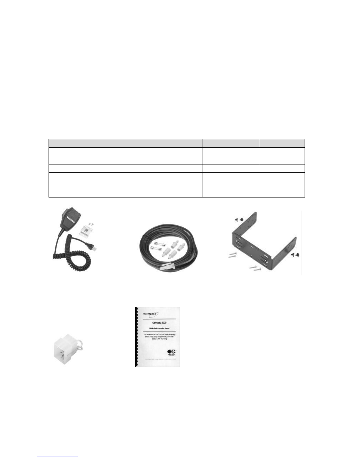
Carefully unpack the transceiver. ComSpace recommends that you identify the items
listed in the following table before discarding the packing material. If any items are
missing or have been damaged during shipment, file a claim with the carrier immediately.
SUPPLIED ACCESSORIES
Item Part Number Quantity
Microphone 700-00000-0100 1
Microphone Hanger Hardware Kit 400-00000-0001 1
DC Power cable, Fuses and Fuse Holders 060-00004-0100 1
Mounting Bracket with Hardware Kit 400-00001-0001 1
Accessory Plug 060-00003-0100 1
Instruction Manual 575-00000-0001 1
Microphone with DC Power Cable, Fuses Mounting Bracket with
Hardware Kit and Fuse Holders Hardware Kit
Accessory Plug Instruction Manual
Page 11
Instruction Manual Page 11 of 25
PREPARATION
WARNING! VARIOUS ELECTRONIC EQUIPMENT IN YOUR VEHICLE MAY
MALFUNCTION IF THEY ARE NOT PROPERLY PROTECTED FROM THE
RADIO FREQUENCY ENERGY WHICH IS PRESENT WHILE TRANSMITTING.
ELECTRONIC FUEL INJECTION, ANTI-SKID BRAKING, AND CRUSE
CONTROL SYSTEMS ARE TYPICAL EXAMPLES OF EQUIPMENT THAT MAY
MALFUNCTION. IF YOUR VEHICLE CONTAINS SUCH EQUIPMENT,
CONSULT THE DEALER FOR THE MAKE OF THE VEHICLE AND ENLIST HIS
AID IN DETERMINING IF THEY WILL PERFORM NORMALLY WHILE
TRANSMITTING.
Note: The following preparation instructions are for use by your ComSpaceCorporation
dealer, an authorized ComSpace Corporation service facility, or the factory.
TOOLS REQUIRED
Note: Before installing the transceiver, always check how far the mounting screws will
extend below the mounting surface. When drilling mounting holes, be careful not to
damage wiring or parts.
The following tools are required for installation of the transceiver:
• ¼ inch (6 mm) or larger electric drill
• drill bits (sizes listed below)
Description Purpose
Drill size 9 (0.196”) Pre-drill 0.196” holes for #12-24 self-threading screws
for use with Mounting Bracket
Drill size 9/64” Pre-drill 0.141” holes for M4x6 self-threading screws
for use with Microphone Hanger
Phillips screwdriver or torx
Drive the self-threading screws into the plastic or metal
driver
Crimp Tool Thomas & Betts No. WT-1300; Radio Shack No. 64-
409; General Electric – U.S. & Metric Terminal Tool
POWER CABLE CONNECTION
CAUTION: THE TRANSCEIVER OPERATES IN 12 V NEGATIVE GROUND
SYSTEMS ONLY! CHECK THE BATTERY POLARITY AND VOLTAGE OF THE
VEHICLE BEFORE INSTALLING THE TRANSCEIVER.
1. Many vehicles provide a hole that is conveniently located in the firewall to allow for
the installation of equipment cables. Check for an existing hole that can be used to
pass the power cable from the engine compartment, through the firewall, to the
passenger compartment.
Page 12

Instruction Manual Page 12 of 25
2. Run the two power cable leads from the passenger compartment through the firewall
and into the engine compartment.
3. Select a location in the two power cable leads for the fuse holder location and cut
each wire at that location.
• Locate the fuse as close to the battery as possible
4. Strip insulation from each end of the two power cable leads that have been cut
(approximately 3/8-inch).
5. Insert wire in fuse holder.
6. Crimp terminal through body.
7. Repeat steps 5 and 6 for other half of the holder and for the holder on the second
power cable lead.
8. Insert fuses in each holder.
9. Snap housing for the two holders together being cautious to keep the holders for the
red lead and the holders for the black lead together.
10. Connect the red lead to the positive (+) battery terminal and the black lead to the
negative (-) battery terminal.
11. Recoil and secure the surplus power cable.
• Be sure to leave enough slack in the cables so that the transceiver can be removed
for servicing while keeping the power applied.
INSTALLING THE TRANSCEIVER
WARNING! FOR PASSENGER SAFETY, THE TRANSCEIVER MUST BE INSTALLED
SECURELY. USE THE SUPPLIED MOUNTING BRACKET TO MOUNT THE
TRANSCEIVER.
1. Mark the position of the holes in the dash or other location of the transceiver within
the passenger compartment by using the mounting bracket as a template. Drill 0.196
inch holes and attach the mounting bracket using the supplied #12-24 thread cutting
screws.
• For user convenience and safety, be sure to mount the transceiver in a location
where the user can easily reach the controls. Also, be sure that there is sufficient
clearance to provide cable clearance for both front and rear and side clearance for
the installation of the thumbscrews that hold the transceiver in the mounting
bracket.
2. Insert the Accessory Plug into the Accessory Connector.
3. With an antenna mounted in compliance with the warning provided in this manual,
connect the antenna and the supplied power cable to the transceiver rear.
Page 13

Instruction Manual Page 13 of 25
4. Slide the transceiver into the mounting bracket and secure it using the four
thumbscrews.
5. Using the supplied M4x6 screws, mount the microphone hanger in a location where it
will easily be in reach of the user.
• It is important that the microphone and microphone cable not be mounted such
that they interfere with the safe operation of the vehicle.
• Use the microphone hanger bracket as a template to mark and drill the 0.141 inch
holes.
6. Connect the microphone to the jack on the front of the transceiver. The connector is
an RJ-45 type and is keyed to allow connection in only one direction. Place the
microphone on the hang up clip.
ANTENNA MOUNTING
Large, flat conductive surfaces provide the best mounting location for the antenna. In
almost all vehicles, the requirement for a large, flat surface are best satisfied by mounting
the antenna at the center of the roof. In the case where the vehicle has a large trunk lid,
the lid provides a good antenna location. If the trunk lid is used, grounding straps should
be connected between the trunk lid and the vehicle chassis to improve grounding of the
lid and ensure it is at chassis ground.
Types of antennas that can be used include:
1. Magnetic Mount Antennas
2. Mobile Window Mounted Antennas
3. Mobile Roof Mount Antennas
Suggested antennas for mobile are listed in the following table:
Manufacturer Model Gain
Application
(dBd)
Maxrad, Inc. MAX8055 5 dB 1 Rooftop, Mag, Trunk Lip
Larsen Electronics KG825UD 3 dB 2 Glass Mount
Antenna Specialists ASPR1980 3 dB 2 Rooftop, Mag, Trunk Lip
Notes:
1
– 5 dBd gain antennas require at least 15 inches (39 cms) separation between the
antenna and any passenger/bystander and 50% operational duty cycle
2
– 3 dBd gain antennas require at least 12 inches (31 cms) separation between the
antenna and any passenger/bystander and 50% operational duty cycle
Antennas with gains of less than or equal to 5 dBd as specified in the above table respect
to the mounting configuration and application comply with the FCC RF exposure
regulations and are allowed for use with this product.
Page 14
Instruction Manual Page 14 of 25
CONTROLS AND CONNECTIONS
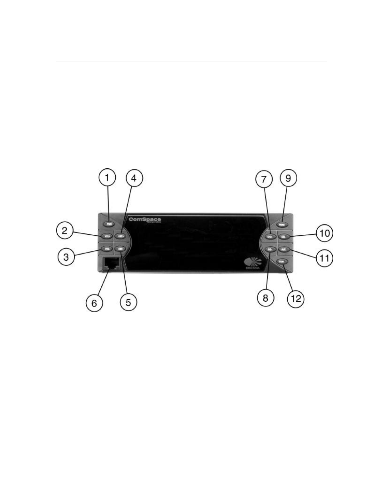
FRONT PANEL
All front panel keys are momentary push buttons and are backlit for nighttime viewing.
Page 15

Instruction Manual Page 15 of 25
PUSH BUTTON FUNCTIONS
Function Description
1
2
3
4
5
6
7
8
Pwr: power on/off Momentarily pressed for power on and held for more than 1
second for power off. At power off, the unit will delay 5 seconds
before shutdown is complete.
Vol+: Volume Up Pressed to increase volume. Held down to continuously increase
volume up to the maximum level. Tone volume varies with
volume.
Vol-: Volume Down Pressed to decrease volume. Held down to continuously decrease
volume down to a mute condition. Tone volume varies with
volume.
Grp+: Group Up Pressed to scroll up in the group list within cur rently selected
system. Held down to scroll cyclically through the groups.
Grp-: Group Down Pressed to scroll down in the group list within currently
selected system. Held down to scroll cyclically through the
groups.
Microphone connector RJ-45 microphone connector.
Sys+: System Up Press the SYS+ button to display current system. A second press
within one second or continuous depression will display a next
to the system number and increment up through the list of
systems. Additional key presses or continuous depression will
result in scrolling up through the systems.
Sys-: System Down Press the SYS- button to display current system. A second press
within one second or continuous depression will display a next
to the system number and decrement down through the list of
systems. Additional key presses or continuous depression will
result in scrolling down through systems.
9
10
11
12
Menu
Sel: Select Used with menu key to enable and/or disable the functions
Aux: Auxiliary Software programmable key.
Scan: System/Group Scan Enables/disables System and Group Scan. Pressed once to
Used with the select key to allow the user to scroll through to a
function and change its value.
selected.
display “Grp-Scan” message and scan the groups. Pressed twice
to display “Sys-Scan” message and scan the systems.
Page 16
Instruction Manual Page 16 of 25
MICROPHONE
The microphone connector is a multi-purpose connector that allows for voice and data.
RJ-45 Microphone Connector Pin-Out
Pin Function Description
2 Microphone Microphone input required for voice. This input is biased
to +VDC with respect to ground.
7 Ground Ground reference for external accessories
5 TxD – Transmit Data Transmit data utilizing XON/XOFF software handshaking
6 RxD – Receiver Data Receive data utilizing XON/XOFF software handshaking
3 PTT Push-To-Talk
4 On/Off Hook Trigger to detect whether the microphone is on/off hook
8 Second Audio Output Future use for external handset
1 +5v 5 volt supply (250 ma maximum current)
DISPLAY
The alphanumeric display will provide all visual indicators.
REAR PANEL CONNECTORS
1 Power Input Connector
2 Accessory Connector
3 Antenna Connector
POWER INPUT CONNECTOR PIN-OUT
Pin Function
1 +12 V
2 Ground
Page 17

Instruction Manual Page 17 of 25
ACCESSORY CONNECTOR PIN-OUT
The connector plug is a MOLEX 03-06-2152. It is a 15-pin connector with several
unassigned pins which are reserved for future use.
Pin Function
13 Speaker – P1 (internal)
7 Speaker – N1 (internal)
14 Speaker – P (external)
8 Speaker – N (external)
11 Ground
4 Horn Honk
5 Ignition (See note)
10 External Speaker Select
1,2,3,6,
Reserved for future use.
9,12,15
Note: All speaker leads (both internal and external) are biased with respect to vehicle
ground and should be not be in contact with vehicle ground.
Note: In the event the vehicle is powered off, the unit detects this condition via the
ignition sense line. A programmable timer establishes when the unit will power
off after detecting that the vehicle has been powered off. This timer is
programmable between 1 minute and 16 hours. If the unit is in Horn-Honk mode,
the mobile will continue with normal operation.
Page 18

Instruction Manual Page 18 of 25
BASIC OPERATIONS
OPERATING FEATURES
The Odyssey 2000 Mobile Unit is the first in a new generation of high performance,
digital transceivers for the Specialized Mobile Radio (“SMR”) and Private Mobile Radio
(“PMR”) marketplace.
TRANSCEIVER FEATURES
• Up to 32 Systems (programmable).
• Up to 250 Groups per system (programmable).
• Up to 512 Groups total (programmable).
• 2 line by 20 characters Alphanumeric display.
• Indication of various operational conditions via the alphanumeric display (volume, PTT, etc.).
TRUNKED SYSTEM FEATURES
• One Home channel programmable per Group: in DC/MA®, a specific frequency, sub-channel,
and slot identify a Home Channel (HC). The maximum number of HC’s allowed per trunking
system is 20. Therefore, LTR assigns 5 bits to this field for Over-The-Air (OTA) protocol.
• One ID code programmable per Group: The maximum number of ID’s as per LTR definition is
250. Therefore, there are 8 bits identifying the ID code OTA.
• Programmable Group and System Scan.
• Programmable transmit inhibit.
• Programmable transponder for each Group.
Page 19
Instruction Manual Page 19 of 25
SYSTEM KEY
Up to 32 systems can be programmed within the unit. Each system can be represented by
up to 17 alphanumeric characters and will also be identified with a number from 1
through 32.
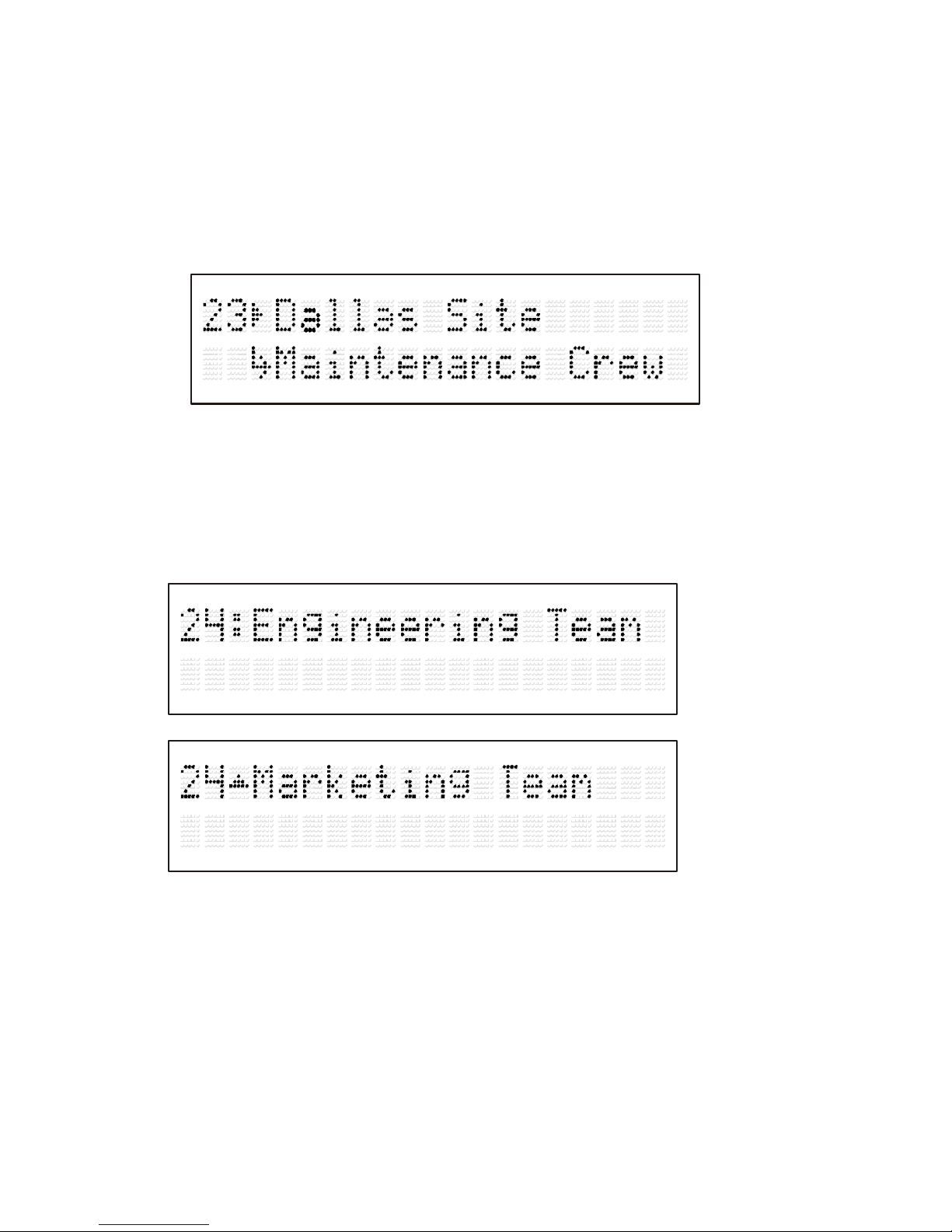
Example System Information Display:
GROUP SOFT KEY
Up to 512 groups can be programmed in the mobile unit. Out of the 512 groups, up to
250 groups can be programmed per system. Each group can be represented by up to 17
alphanumeric characters. The group name will follow the system number on the top
display line.
Group Information Display (Pressing the key twice)
VOLUME SOFT KEY
The two volume soft keys control the volume levels. There are a total of 28 volume
steps in the volume table.
Page 20
Instruction Manual Page 20 of 25
VOLUME SPECIFICATIONS
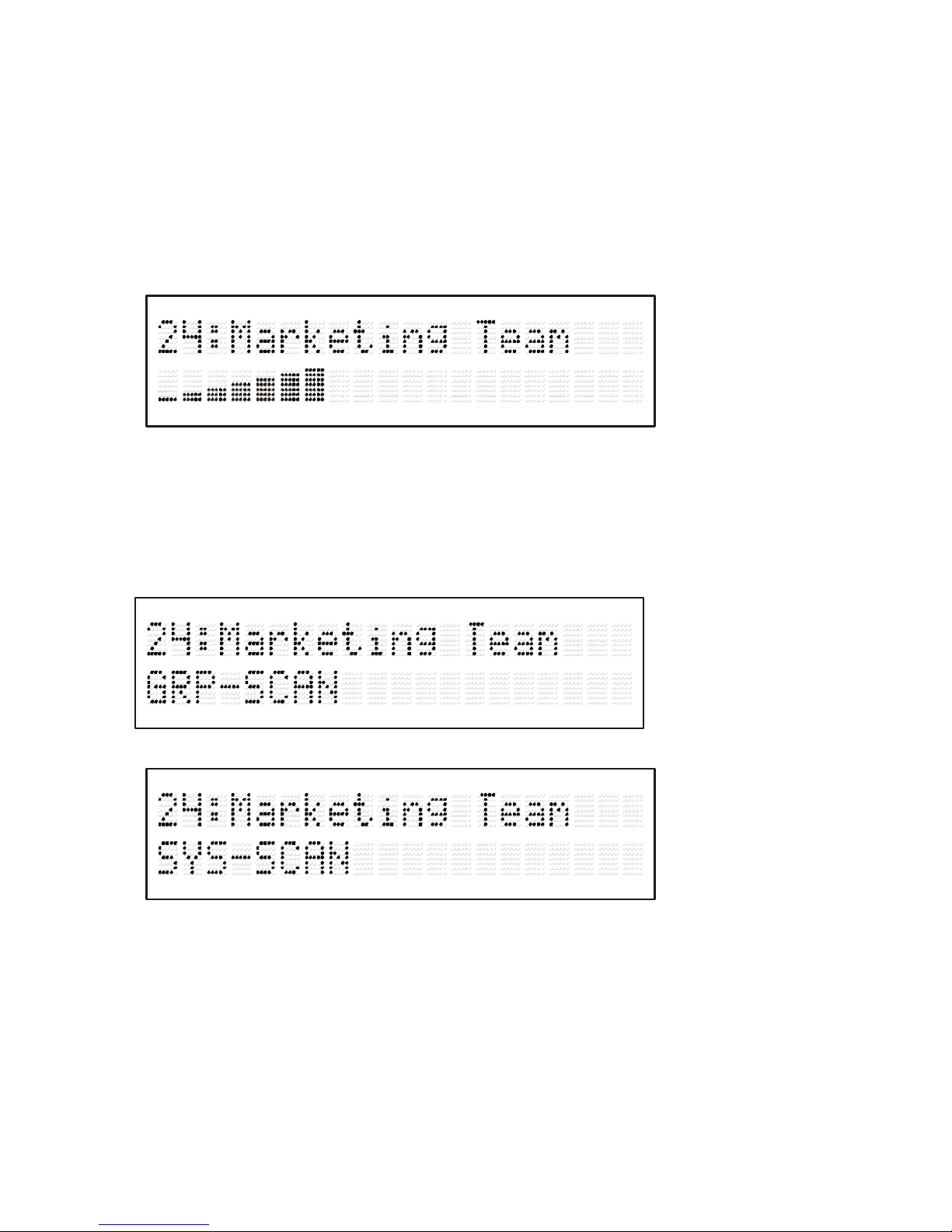
There are 28 settings for the speaker volume. Step 1 is mute. Steps 2 through 28
provide approximately an approximate 2 dB per step. The volume is displayed
using rows of the 5 x 7 character display matrix. Each of the seven rows of the
display character matrix represents 4 levels of the total range.
Example Volume Level Display (shown at full volume)
SCAN SOFT KEY
The Scan soft key has two purposes. It enables and disables both System and Group
Scan.
Example Group Scan
Example System Scan:
MENU AND SELECT SOFT KEY
The menu and select keys are to be utilized together. The menu soft key allows the user
to scroll through to the function that needs to be enabled and/or disabled. Each menu
selection can be represented by up to 17 alphanumeric characters. The select key is used
to enable and/or disable the functions previously selected with the use of the menu key.
When scrolling through the menu selection, the options are listed on the status line as
well as the status of the function.
Menu Selections:
Page 21

Instruction Manual Page 21 of 25
Display Intensity There are four levels of intensity with the VFD display, 25 percent,
50 percent, 75 percent, and 100 percent. Using the menu soft key,
scroll to the “Display XX%” menu location.
Horn-honk Toggle the Horn-Honk feature ON and OFF. (Enabled by option)
Group Display Toggles group display between a pre-programmed label and a group
number.
Home Group Automatically takes the user back to home group within the currently
selected system.
FCC ID Display FCC ID
Page 22

Instruction Manual Page 22 of 25
TONE INFORMATION:
ALERT TONE DEFINITIONS
All of the tones follow the LTR convention as described by E.F. Johnson.
GENERIC TONES
General tones are tones that are generated for more than one function. The
following is a list of tones that fall into the generic class.
Tone
Key Touch
Description
700 Hz, 40 msec tone - indicates when a soft key is pressed
Tone
Wrap Around
Tone
700 Hz, 80 msec tone followed by an 800 Hz, 80 msec tone –
indicates that the highest or lowest programmed system or group was
displayed and that wrap-around has occurred
Error Tone 1050 Hz, 80 msec tone followed by a 700 Hz, 80 msec tone –
indicates an error condition occurred. For example:
HORN HONK NOT ALLOWED, PROGRAMMING ERROR, etc.
Page 23

Instruction Manual Page 23 of 25
SPECIFIC TONES:
Specific tones are tones that have one function only. Their function is not described
in this section. Only how the tone is generated is described in this section.
Tone
Description
POWER ON/OFF 1400 Hz, 200 msec tone – indicates that power to the unit is
ON and that it is safe to release the power button
SYSTEM BUSY Tone similar to the standard telephone busy tone – indicates
that the LTR radio system is currently busy. Note: Produced
by turning combined 480 and 620 Hz tones on and off at a 5
Hz rate.
CALL GRANTED tone composed of two short 700 Hz, 20 msec tones, separated
by a short 900 Hz, 20 msec tone – sounds after the call has
been granted upon pressing PTT to indicate when talking can
begin
CHANNEL
AVAILABLE
Composed of three short 1000 Hz, 20 msec tones, separated
by two short 1200 Hz, 20 msec tones – sounds after the radio
has been waiting in queue for an available channel
Intercept Siren-like tones consisting of 700 Hz and 800 Hz tones
alternating at approximately at 2 Hz rate – indicates error
conditions like: OUT OF RANGE, TRANSMIT INHIBIT,
RECEIVE ONLY CHANNEL, TRANSMIT WHILE
RECEIVING, and TIME-OUT TIMER.
AUX FUNCTION
ACTIVE
a short (900 Hz, 40 msec) tone that sounds to indicate that the
Aux function key is now activated/deactivated.
TIME OUT TIMER
WARNING
a short high beep 1400 Hz, 20 msec tone to indicate that the
Time-Out timer is about to go off
INCOMING CALL This is composed of two short 1400 Hz, 40 msec tones,
separated by one short 1000 Hz, 40 msec tones which sounds
a call is received.
VOLUME SET 900 Hz.tone to indicate the volume setting level.
ENTERED
PROGRAMMING
MODE
a 1000 Hz, 40 msec tone, followed by a 1200 Hz, 40 msec
tone, followed by a 800 Hz, 40 msec tone, repeated twice
back to back
Page 24

Instruction Manual Page 24 of 25
TRUNKED OPERATION
PLACING A DISPATCH CALL
1 Select the desired system and group using the System and Group keys.
2 Press the PTT Switch
3 If a tone does not sound, communication is possible; start speaking into the
microphone. Release the PTT switch to receive.
• For best sound quality at the receiving station, hold the microphone
approximately 1.5 inches (3 ~ 4 cm) from your mouth and talk across the
microphone not directly into it.
4 When your conversation is finished, return the microphone to the hang up clip.
RECEIVING A DISPATCH CALL
1 Select the desired system and group using the System and Group keys. (If
the Scan function has been programmed, it can be switched ON or OFF as
desired.)
2 When the dispatcher’s voice is heard, readjust the volume as necessary.
Page 25

Instruction Manual Page 25 of 25
Conventional Operation
TRANSMITTING
Note: Before transmitting, monitor the channel to make sure it is not already in use.
1 Select the desired system and group using the System and Group keys.
• If the channel is busy, wait until it becomes free.
2 Press the PTT switch and speak into the microphone. Release the PTT switch to
receive.
• For best sound quality at the receiving station, hold the microphone
approximately 1.5 inches (3 ~ 4 cm) from your mouth and talk across the
microphone not directly into it.
3 When the conversation is finished, return the microphone to the hang up clip.
RECEIVING
1 Select the desired system and group using the System and Group keys.
2 When you hear the dispatcher’s voice, readjust the volume as necessary.
 Loading...