

Page 1

??? NEED HELP ???
APPLYING FOR YOUR QUALIFIER
TRANSMITTER LICENSE
We have included on the Feature Installation Software
CD a folder full of instructions, application templates
in Microsoft Word and Acrobat formats along with
helpful web sites to get you up and running in no time.
Please browse to and open the file named Customer
Packet. Read the Adobe Acrobat document Read Me
First.
If you encounter difficulty, please give our Customer
Service Representatives a call. They will be glad to
help.
1-800-336-9681
Page 2

Page 3
H
OOMMEE
H
Q
UUAALLIIFFIICCAATTIIOON
Q
N
U
U
G
G
Digital Level Capability
Home Qualification Features
S
YYSSTTEEM
S
s
s
u
u
Signal Level Meter
with
and
e
e
i
i
M
d
d
r
r
e
e
CSI Document 101268-001 Rev. C unreleased
Page 4

Warranty
ComSonics, Inc. warrants this product to be free of material and workmanship defects for a period of one year
from the original date of shipment.
Remedies provided under Warranty are exclusive and in lieu of all other warranties express or implied. The
liability to ComSonics is limited to product repair or replacement at the discretion of ComSonics. ComSonics
shall not be held liable for any incidental or consequential damages.
The following are not covered by this warranty:
1) Parts or components not supplied by ComSonics, or parts or components that have been modified.
2) Any product or part failure that results from accident, abuse, misuse, neglect, or unauthorized repairs or
modifications by individuals other than ComSonics personnel.
3) Failures caused by use of this product in extreme climates or moisture conditions.
4) CyberTek Qualifier Battery Pack
Technical Support
ComSonics maintains a Technical Support Service for customer convenience. Should the need arise, contact a
Technical Support Representative by telephone at 1-800-336-9681 or 1-540-434-5965; Fax at 1-540-432-9794;
or Email at tech-support@comsonics.com.
Return Information
Products returned for repair, calibration, etc. must be safely packed. Please enclose information on the reason
for return. Ship the material prepaid.
All material in this manual is the property of ComSonics, Inc. and is protected under the United States
copyright law. No material shall be reproduced or used in any form or by any means (graphic, electronic, or
mechanical, including photocopying, recording, taping, or information storage and retrieval systems) without
the written permission of:
ComSonics, Inc.
1350 Port Republic Road
Post Office Box 1106
Harrisonburg, Virginia 22801 USA
Phone: (540) 434-5965 USA Toll Free: (800) 336-9681
Fax: (540) 434-9847
Email: marketing@comsonics.com
Internet: www.comsonics.com
Agency Notice
Changes or modifications not expressly approved by the manufacturer could void the user’s authority to
operate the equipment.
FCC ID: PYN12002A vehicle mounted device
FCC ID: PYN22002B hand held device
This device complies with Part 15 of the FCC Rules. Operation is subject to the following two conditions: (1)
this device may not cause harmful interference, and (2) this device must accept any interference received,
including interference that may cause undesired operation.
This Class B digital apparatus complies with Canadian ICES-003.
Cet appareil numérique de la Classe B est conforme à la norme NMB-003 du Canada.
CyberTek Qualifier and WindowLite
are trademarks of ComSonics, Inc.
2002 ComSonics, Inc. All Rights Reserved
Document No. 101268-001 Rev. C unreleased
Page 5

Qualifier System
Table of Contents -
Signal Level Meter and Home Qualification System
Specifications .................................................................................................................... iii
Description ...................................................................................................................... 1-1
Battery Care .................................................................................................................... 1-2
Power-Up ........................................................................................................................ 1-3
User Preferences ............................................................................................................. 1-4
Country Set Define .................................................................................................. 1-5
Units of Measure Define .......................................................................................... 1-6
Quick-Tune Channels Define .................................................................................. 1-7
Making Measurements .................................................................................................... 1-8
Backlight ....................................................................................................................... 1-11
Home Qualification System - Overview ......................................................................... 2-1
Hardware Installation ...................................................................................................... 2-2
System Operation ............................................................................................................ 2-8
Qualifier Transmitter Details ................................................................................... 2-8
Qualifier Meter Details ............................................................................................ 2-9
Appendix A: Keypress Reference .................................................................................. 3-1
Appendix B: Channel Line-Up Set and Country Set Codes ........................................... 3-2
Appendix C: Feature Installation Utility ........................................................................ 3-3
Appendix D: Pressure Relief .......................................................................................... 3-6
Appendix E: Battery Replacement ................................................................................. 3-7
Appendix F: Theory of Operation .................................................................................. 3-8
Transmitter Block Diagram ..................................................................................... 3-8
Meter Block Diagram .............................................................................................. 3-9
Appendix G: Home Qualification System - Generalized Theory of Operation ........... 3-10
Appendix H: European Community Declaration of Conformity ................................. 3-16
i
Page 6

Qualifier System
FCC License Requirement
A FCC license is required to operate the CyberTek Home Qualification
System, specifically the transmitter component. Contact your ComSonics
representative for assistance in this matter.
CAUTION !
The Cybertek Home Qualifier System must be installed in a service
vehicle equipped with a 12-volt negative ground electrical system.
Note:
The battery charger for the Qualifier Signal Level Meter is designed to
be used only with 120VAC power from a wall outlet. Use of other
power sources, such as a vehicle inverter, may reduce the usability of
the meter.
ii
Page 7

Specifications - Qualifier System
Qualifier Signal Level Meter - General Specifications
Tuning range
Amplitude range
Amplitude accuracy
Analog Television Types
Digital Modulation Types
Tuning increments
Tuning accuracy
Auto-seeking range
(Direct access) quick-tuned
channels
Step-tuned channels
Pre-loaded channel sets
Audio Output
Qualifier Mode
Frequency
Activation Distance
5.00 MHz ~ 860.00 MHz
-30 dBmV (+30 dBmV) ~ +40 dBmV (99.9 dBmV)
±1.0 dB at room temperature; ±1.5 dB over operating temperature
NTSC / PAL; peak carrier sync, preprogrammed audio offset
QPSK, QPR, QAM, and VSB; bandwidth up to 20 MHz
Fixed (tuned by pre-loaded tables)
Auto-seeking to ≤ 62.5 kHz
±312 kHz
6 channels - user-configurable (factory pre-sets per Country Set)
Pre-loaded channel set dependent
25 standard, picture carrier plus associated sound carrier
Frequency modulation detector produces low impedance output to
earphone jack (earphone optional)
27.450, 27.470, or 27.490 MHz
Up to 150 feet between receiver and transmitter
Qualifier System
Power
Battery
Battery recharge life
Size / Weight
Size
Weight
Environment
Storage temperature range
Operating temperature range
Humidity
Shock
Qualifier Transmitter - General Specifications
RF Output Power
Frequency
Input Supply Voltage
Size
Weight
Storage Temperature
Operating Temperature
Humidity
User rechargeable, 6.0 V @ 0.55 Ah
> 550 measurements*
7.7” high X 3.5” wide X 2.3” deep (19.6 cm X 8.9 cm X 5.8 cm)
23 oz. (0.65 kg)
-20 °F ~ 150 °F (-29 °C ~ 66 °C)
0 °F ~ 120°F (-18 °C ~ 49 °C)
Weather resistant (withstands total immersion into 1 foot of water for
30 minutes without intrusion)
Uniquely rugged
5 watts
Factory set to 27.450, 27.470, or 27.490 MHz
Vehicle power - 12 volts DC negative ground
7.7” x 4.4” x 1.7” less connectors and mounting bracket
2.5 lb
-20°F ~ 150°F
0°F ~ 120°F
5% ~ 95% (non condensing)
*Beginning with a new, fully charged battery. Room temperature lab tests produced more than 1,100 measurements by
repeatedly activating F1through F6 at 10 second intervals until automatic shut-down occurred.
iii
Page 8

Qualifier System
This page intentionally left blank.
iv
Page 9
Description
Qualifier Meter
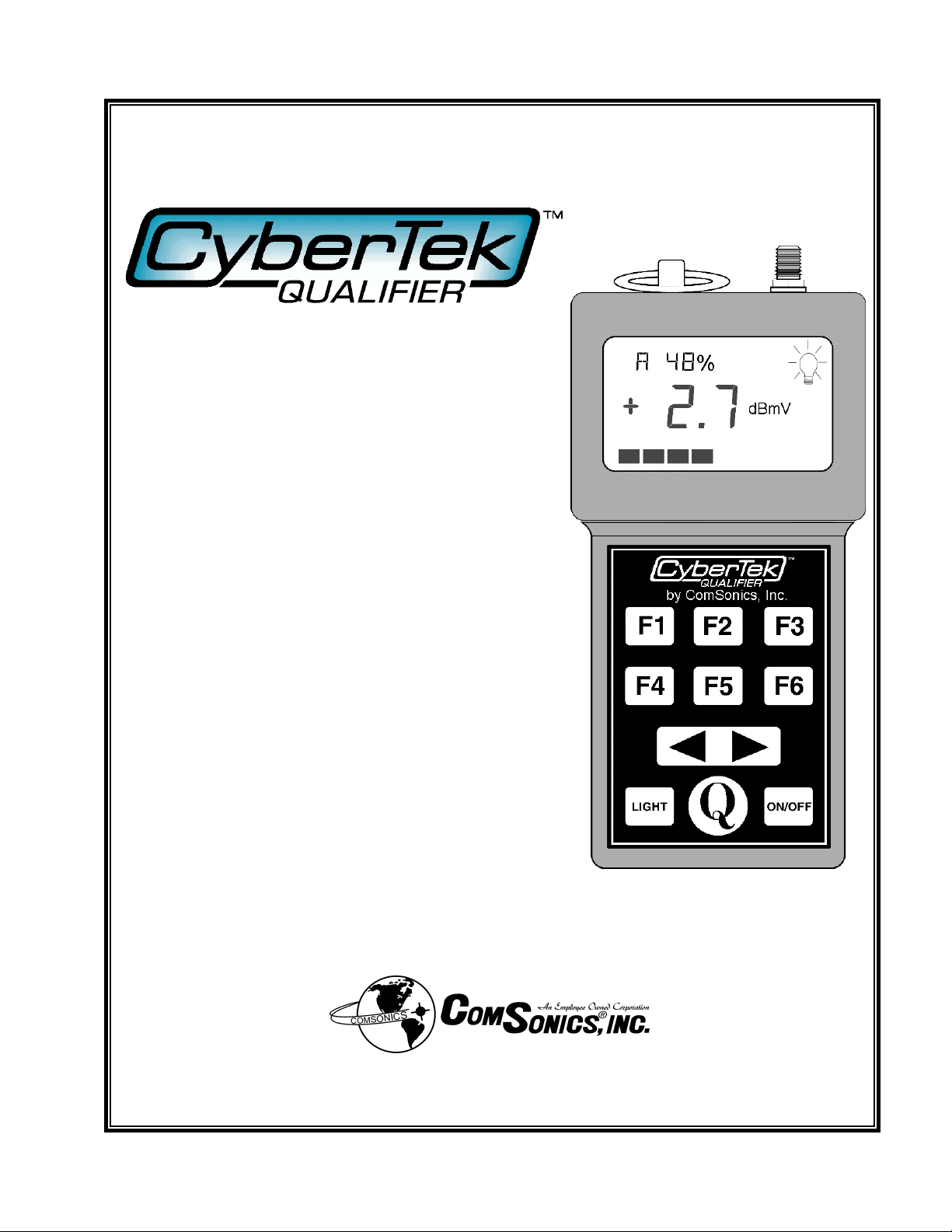
The ComSonics CyberTek Qualifier is a signal
level meter dedicated to the CATV installer. It
features the ability to easily choose for
evaluation any one of six pre-selected channels
from the full tuning range available. The
Qualifier meter makes measurements on the
chosen channel with a single keystroke,
showing the results on a backlight-capable
liquid crystal display (LCD).
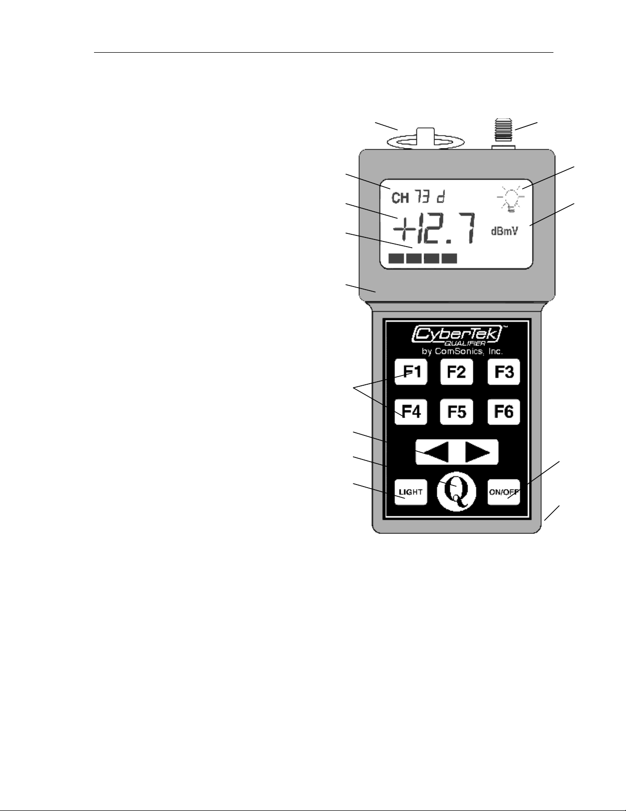
The Qualifier meter’s controls have been
simplified to make its operation as easy as
possible. The keypad has six function keys (F1
through F6), each capable of tuning a picture
carrier frequency and its sound carrier
frequency or a single digital channel in the 5
MHz to 860 MHz range. It also has arrow keys
for single step tuning the unit within this range.
There are keys to control the backlight feature
as well as for powering the unit on and off. The
LCD features the channel being measured, its
level readout, and the unit of measure. A light
bulb symbol appears when the backlight is in
use; a battery symbol appears when the battery
level is low. Unless the battery charge life is
nearing an end, a bar graph shows the relative
signal strength. When the battery symbol is
present, the bar graph indicates remaining
battery life.
4
8
3
10
14
11
2
9
1
5
76
12
13
1-1
Input
1
Lanyard Ring
2
ABS plastic housing
3
Tuned channel
4
Backlight indicator
5
Level indicator
6
7
Units of measure (dBmV or dB
8
Level strength indicator
9
Function (channel) keys
10
Arrow selection keys
11
Backlight key
12
Power ON / OFF key
13
Earphone jack
14
Qualifer Mode key
µ
V)
Page 10
Qualifier Meter
Battery Care
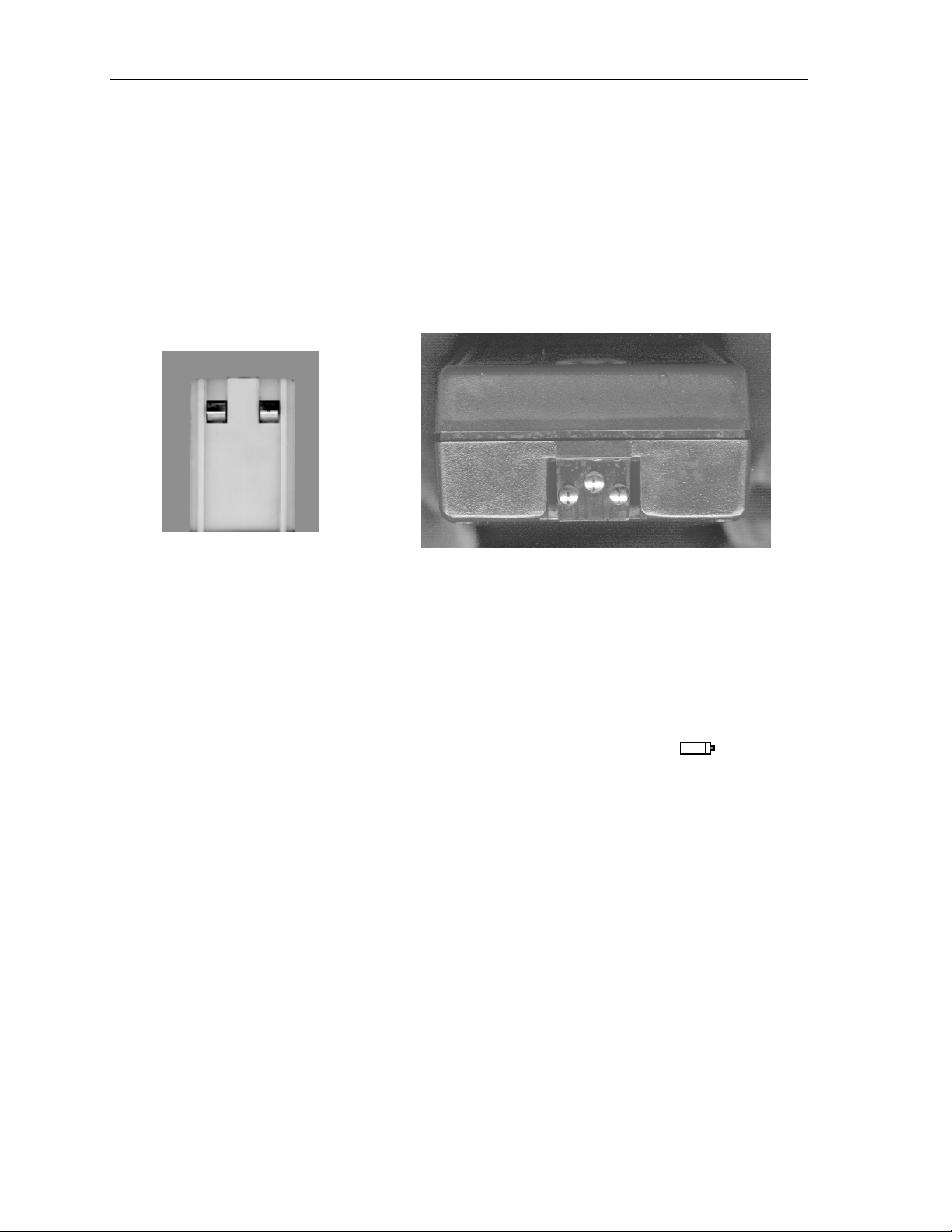
The Qualifier meter uses a rechargeable battery. For recharging this battery, ComSonics
includes a single-unit battery charger as a standard accessory.
The single-unit charger’s contact end (see illustration) consists of a yellow plastic housing,
with flanges on either side, and two spring-loaded prongs. It fits into the slot on the bottom
edge of the Qualifier meter, which has contacts corresponding to the charger prongs (see
illustration).
Prongs of a single-unit charger Contact end of Qualifier metert and points
To engage the contacts properly, hold the Qualifier meter face up, place the charger
connector so the flanges fit into the corresponding grooves in the Qualifier meter’s contact
end, and push towards the front of the Qualifier meter. When the charger connector is
completely inserted, the prongs will be in contact with the Qualifier meter’s contact points.
Plug in the charger pack to begin recharging your Qualifier meter. Fully recharging a
depleted battery takes approximately 10 to 16 hours.
When the battery charge drops below a set level, the battery low indicator ( ) appears.
The bar graph of the display blinks while this indicator is present, and shows the relative
amount of charge remaining.
1-2
Page 11

Qualifier Meter
Power-Up
When first powered-on, Qualifier meter is in a low power state to reduce battery
consumption. In this state, the LCD provides the user with the channel name, units of
measure, the last measured value and a bar graph. “Backlight” and/or “Battery Low”
annunciators may also appear.
123
4
7
56
1
2
3
4
5
6
-OR-
7
The selected channel name in the format [CH XX88 X]. CH for channel, followed
by the channel name comprised of a combination of two alpha-numeric and two
numeric characters. The channel name is followed by P for picture carrier, or S
sound carrier, or A for channels with a second audio channel, or d for a programmed
digital channel. Digital channels are user programmed via a computer program. See
section Feature Installation Utility.
Battery symbol is illuminated if a battery low condition is sensed.
SETUP is illuminated when the User Preference mode is activated.
Lightbulb symbol is illuminated if the backlight is active.
dBmV or dBµV Units of Measure conforming to internationally used conventions.
The bar graph provides a visualization of the measured signal level relative to the
total dynamic range.
The bar graph provides a relative indication of the remaining battery life while the
battery low signal is activated.
At Power-Up, the measured value displays the level of the last channel measured
prior to power-down. The display updates with each function keypress.
1-3
Page 12

Qualifier Meter
User Preferences
Three built-in features are available for the user to customize the Qualifier meter: the
Country Set, the Unit of Measurement and the selection of six Quick-Tune Measurement
Channels.
One custom user channel line-up set or group can be created and installed to the Qualifier
meter using the Feature Installation Utility. The utility is a PC Windows program necessary
for the customization and installation of a user defined channel set. Digital channel
definitions can only be installed by use of the utility. See section Feature Installation Utility
for more details.
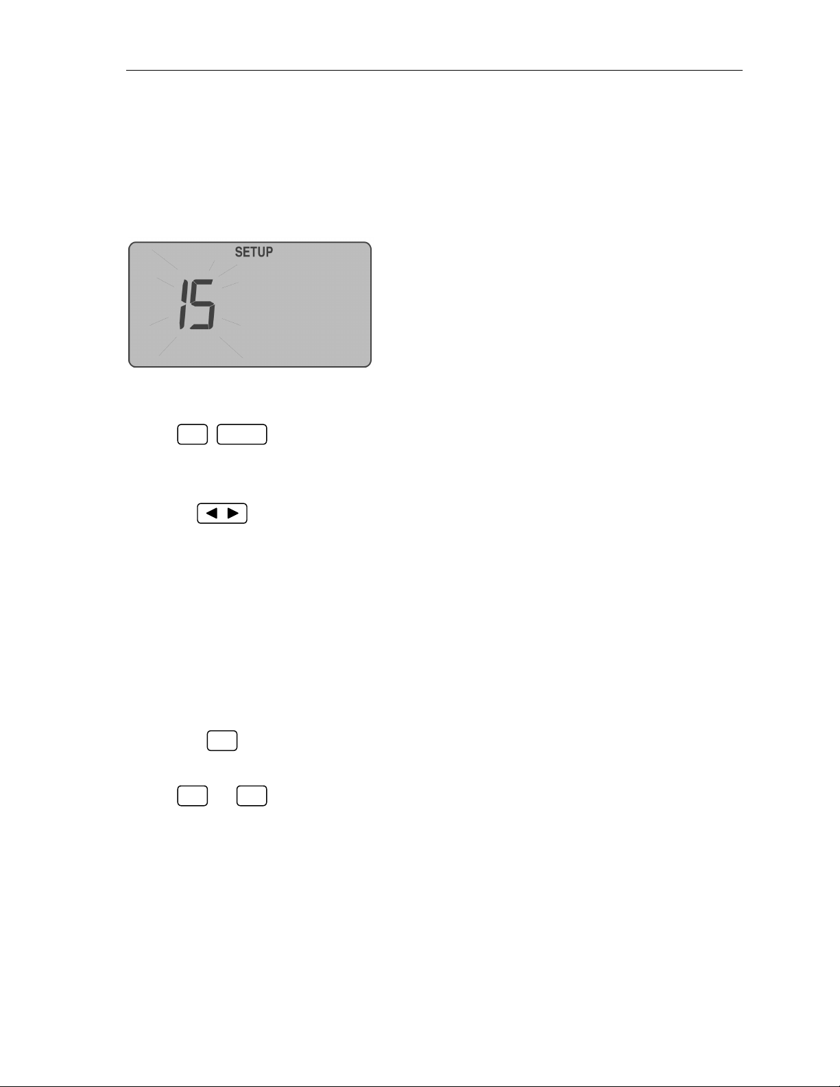
User Preferences are made available sequentially to the user through the SETUP mode. In
each sequence, the display blinks, showing current settings. Any displayed setting can be
changed with the arrow keys or left alone; changes are saved automatically.
To enter the SETUP mode, press and hold F6 while powering the unit ON using the
ON/OFF key.
Automatically, the Qualifier meter activates the Country Set Define sequence. The
currently selected Country Set code number blinks. Arrow keys step through the sets
available (see Appendix B for a complete listing). Pressing F1 leaves this sequence and
initiates the Units of Measure Define sequence.
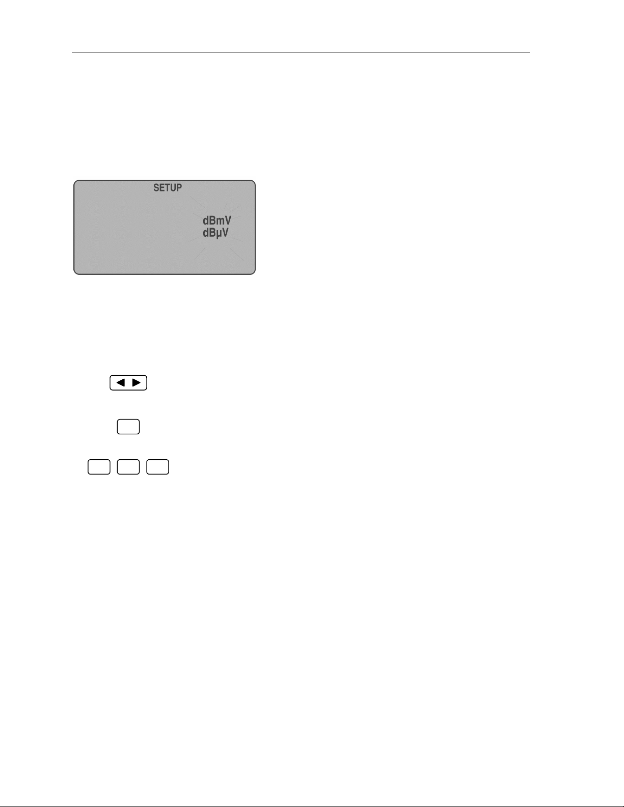
The Units of Measure Define sequence of the SETUP mode is indicated by a blinking
Units of Measure selection. Pressing either the right or left arrow key toggles between
dBmV and dBµV. Pressing F2 ends this sequence and activates the Quick-Tune Channels
Define sequence.
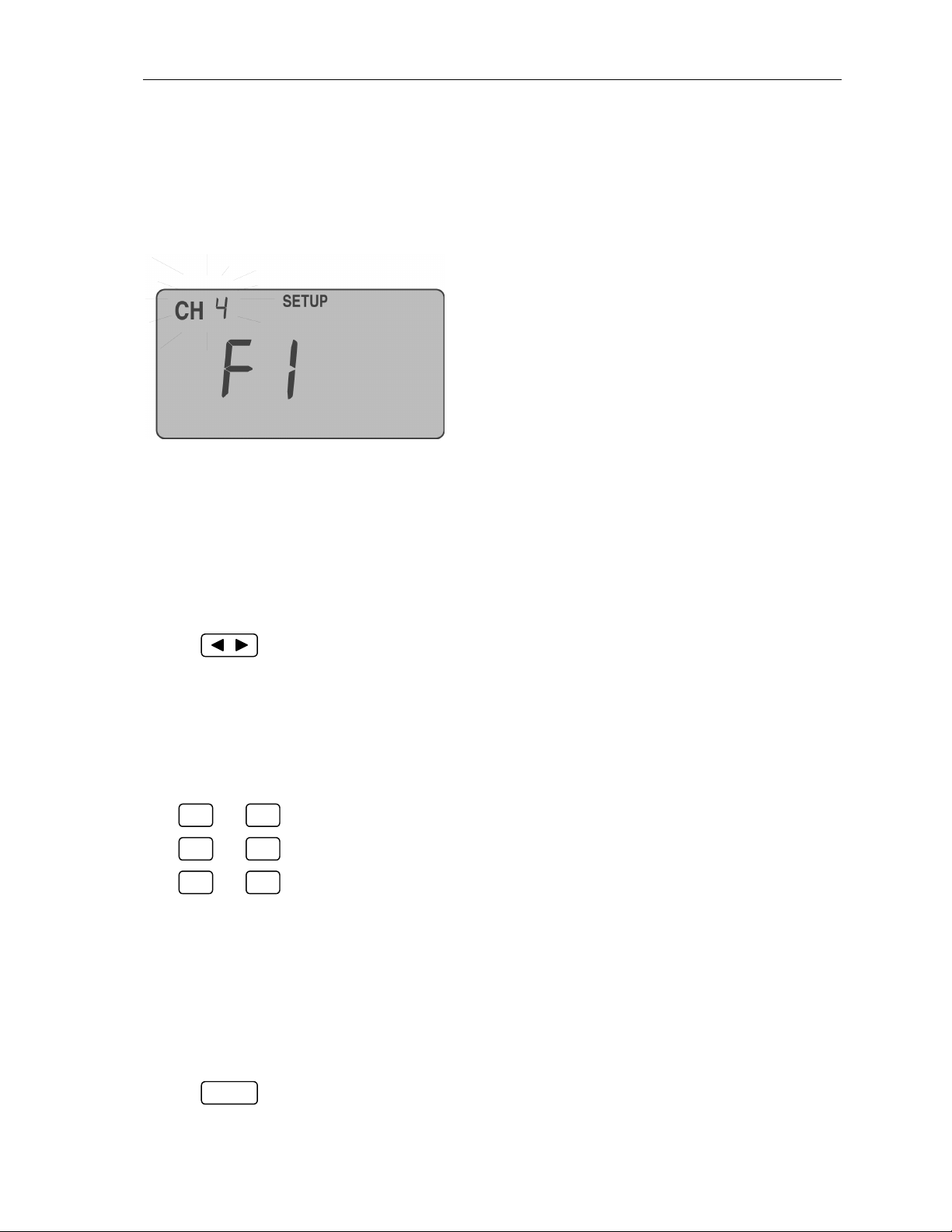
The Quick-Tune Channels Define sequence is the final stage of the setup mode. F1
through F6 can refer to any six picture/sound carrier pairs contained within the selected
Country Set. At the beginning of the sequence, the channel display blinks, showing the
setting for F1. Press any of the six function keys, and the unit displays the current video
carrier channel setting. (If the unit has never been programmed, or if a new Country Set has
been selected in the SETUP mode, the factory preset channel for that function key is
displayed.) Use the arrow keys to change the channel setting if desired. This can be done for
each function key, in any order, and more than once if desired.
End the SETUP mode by pressing ON/OFF; this saves the setup and shuts the unit off.
1-4
Page 13
Qualifier Meter
Country Set Define
From a preprogrammed list of countries, the user selects the one best suited to their area by:
(a) placing the Qualifier meter into SETUP mode; (b) keying to the desired Country Set.
• Country sets are displayed (1 to 25).
• See the Appendix section for a listing of the available countries and their access codes.
Changing the Country Set automatically changes the channel
settings to a default set of channels for that country set.
During this sequence, the Channel Name, Units of Measure,
and the Bar Graph are suppressed from the display.
STEP KEYPRESS RESULTS
+
1. Power-on the Qualifier meter in SETUP mode; this activates
F6 ON/OFF
Country Set Define sequence. The current Country Set code blinks,
indicating that this code can be changed.
2. Scroll through the available country sets:
scrolls forward (1 to 25, with the standard configuration),
rolling over to the first set when the last set is passed.
scrolls backward, rolling over to the last set when the first set
is passed.
Note: If a user channel set is installed, the country set range is 0 to 25. Set 0 is
the user channel set. See section Feature Installation Utility for more details.
Important: To reinitialize a country set, scroll forward by at least one number
and then scroll back to the desired country set. The Quick-Tune keys and the
channel center frequencies (learned) are reset to default whenever the county set
is changed.
3. The device continues to the next sequence in the SETUP mode,
F1
Units of Measure Define, described on the next page.
~
F2 F6
Keys remain inactive during Country Set Define.
Going straight to Step 3 below
without touching leaves
current Country Set Define setting
unchanged and continues to the
next sequence in the SETUP mode,
Units of Measure Define.
1-5
Page 14
Qualifier Meter
Units of Measure Define
The Qualifier meter makes available two Units of Measure to provide worldwide
measurement compatibility. The user selects between dBmV and dBµV by: (a) placing the
Qualifier meter into Units of Measure Define mode; (b) choosing between dBmV and
dBµV; and (c) selecting Quick-Tune Channels Define.
During this sequence, the Channel Name, Measured Value, and
the Bar Graph are suppressed from the display.
(continued from previous page)
STEP KEYPRESS RESULTS
The dBmV / dBµV display blinks, indicating that this setting can
be changed.
4. Toggles between dBmV and dBµV. or may be used.
5. The device continues to the next sequence in the SETUP mode,
F2
Quick-Tune Channels Define, described on the next page.
~
,
F3 F6F1
Keys remain inactive during Units of Measure Define.
Going straight to Step 5 leaves
current Units of Measure Define
setting unchanged and continues to
the next sequence in the SETUP
mode, Quick-Tune Channels Define.
1-6
Page 15
Qualifier Meter
Quick-Tune Channels Define
The Qualifier meter’s function keys allow the user to easily tune to one of 6 preselected
channels. Choices are selected for the key locations by: (a) placing the Qualifier meter into
the SETUP mode; (b) stepping to the Quick-Tune Channels Define sequence; (c) selecting
channel choices; and (d) changing the displayed setting (any change is automatically stored).
During this sequence, the Measured Value, Units of
Measure, and the Bar Graph are suppressed from the
display.
If the unit has never been programmed (or if a new Country
Set has been entered in the Country Set Define sequence),
the channels displayed in this function will be channel
defaults determined by the Country Set; otherwise the last
channel values programmed for each key will be displayed.
(continued from previous page)
STEP KEYPRESS RESULTS
The Selected Channel setting blinks, displaying the video carrier
setting stored under F1. NOTE: The display will blink if the
channel has never been tuned before, or is changed here; if the
channel has been previously tuned, it will not blink.
6. Change the channel setting:
Increments setting from a low channel to a high channel;
Increments setting from a high channel to a low channel.
No additional keypresses are required to lock a setting. Pressing
or changes and stores the setting simultaneously. If or
are not used, the setting is not changed. Changes will be effective at
the next power-up.
or
F1
7. The display will react as above for the selected function key.
or or
F3
or
F5
F2
F4
F6
or
8. Repeat Step 6 for as many function keys as desired.
If you wish to tune a channel at this time, press the function key indicated on the display to
have the Qualifier meter search for a center frequency. If the center frequency is found, the
F Key indicator ceases to blink. If the center frequency is not found, the F Key indicator will
continue to blink. (In measurement mode, the center frequency search process takes place
automatically when a channel is selected for the first time.)
9. Ends the SETUP mode and shuts off the unit.
ON/OFF
1-7
Page 16

Qualifier Meter
Making Measurements
Each user request for a measurement causes the Qualifier meter to tune to the channel
assigned to the function key pressed: the Qualifier meter displays the picture carrier, and
another press of the same key toggles to the sound carrier, and subsequent keypresses toggle
back and forth between the two. First-time tuning may experience a slightly longer delay
than subsequent measurements as the Qualifier meter learns and stores the exact location of
the carriers within the channel. (This will happen once for each function key selection; it can
take place here or during the SETUP mode. See section Quick-Tune Channels Define.)
Several samples of the tuned channel peak amplitude are measured, averaged, augmented
with temperature and characteristic data particular to each instrument, and displayed. The
value is displayed as the Qualifier meter changes to a low power mode. Automatic power
down occurs if a key is not pressed for 1 minute. Repowering always furnishes the last
measurement made before power-down. The value will be blinking to serve as a reminder
that a previously measured value is being displayed.
is also active during normal measurement
operation; automatic power-down occurs if keys remain idle
for 1 minute.
During measurement mode, if the signal is less than
-30 dBmV, the display substitutes LO for the signal level
readout. If the signal level is greater than 40 dBmV, the
display substitutes HI for the signal level readout.
As an additional aid to verification of tuned signals, the Qualifier meter produces a low
impedance sound signal, provided through the earphone jack in the Qualifier meter’s case.
This sound signal is extracted by the Qualifier meter from sound, picture, digital, or other
carriers. When a channel is tuned by pressing an arrow key or one of the function keys,
sound can be heard through an earphone connected to the earphone jack. The sound is
turned on 15 seconds for video and 20 seconds for audio. (This is to preserve battery power.)
Signal level measurements are made by (a) powering-on the Qualifier meter, and
(b) selecting the channel to tune: first the picture carrier, then the sound carrier.
1-8
Page 17

Making Measurements
STEP KEYPRESS RESULTS
Qualifier Meter
F1
ON/OFF
or
F2
or
1. Power-on the Qualifier meter.
2. Requests tuning to pre-defined location, measures value, displays
value of the picture carrier; a second press of the key toggles to the
or or
F3
F5
F4
or
F6
sound carrier, another press toggles back to the picture carrier.
Pressing F1 for instance, displays the picture carrier of that channel;
pressing F1 again displays the sound carrier; pressing F1 yet again
displays the picture carrier again. (Channels with a second audio
carrier behave differently: see the next page.)
3. Allows tuning from the currently displayed channel to another in
the country set sequence. As each channel has a picture and a sound
carrier channel, the sequence would be picture - sound - picture if
starting from a sound channel, or sound - picture - sound if starting
from a picture channel.
Note:
For user modified channel sets containing digital
channels, a ‘d’ appears
when a digital channel is
selected. A digital channel has just one tuning
selection. It does not
have separate picture
and sound carrier measurements. When a digital
channel is selected,
pressing moves to the
next lower channel or
pressing moves to the
next higher channel.
If the Qualifier meter displays the picture carrier for Channel 3, for
instance, pressing displays the sound carrier of Channel 3;
pressing again displays the picture carrier of Channel 4. If the
Qualifier meter displays the sound carrier for Channel 3, pressing
displays the picture carrier of Channel 4; pressing yet again
displays the sound carrier of Channel 4.
Similarly, if the Qualifier meter displays the picture carrier for
Channel 3, pressing displays the sound carrier of Channel 2;
pressing yet again displays the picture carrier of Channel 2. If
the Qualifier meter displays the sound carrier of Channel 3, pressing
displays the picture carrier of Channel 3; pressing yet again
displays the sound carrier of Channel 2.
Picture
When pressing at the upper range, or at the lower range, the
tuning loops back. Pressing when the Qualifier meter displays
the sound carrier of the last channel causes the device to display the
picture carrier of the first channel. Pressing when the Qualifier
meter displays the picture carrier of the first channel causes the
device to display the sound carrier of the last channel.
Current
Channel
to Last Channel Sound to First Channel Picture
Sound
Next
Channel
Picture Sound
The Qualifier’s tuning hierarchy
…………….………………
1-9
Last
Channel
Picture Sound
Page 18

Qualifier Meter
d
d
d
Making Measurements
(Second Audio Carrier Channels)
Some Country Sets include channels with second audio carriers; the keypress sequences for
these channels are different.
STEP KEYPRESS RESULTS
1. Power-on the Qualifier meter.
ON/OFF
2. Requests tuning to pre-defined location, measures value, displays
F1
F3
F5
or
or or
or
F2
F4
F6
or
value of the picture carrier; a second press of the key toggles to the
sound carrier, a third press toggles to the second audio carrier, and a
fourth press toggles back to the picture carrier. Pressing F1, for instance, displays the picture carrier of that channel; pressing F1
again displays the sound carrier; pressing F1 yet again displays the
second audio carrier; pressing F1 once more displays the picture
carrier again.
3. Allows tuning from the currently displayed channel to another in
the country set sequence: sound - 2nd audio - picture - sound if
starting from a picture carrier, or 2nd audio - picture - sound - 2nd
audio if starting from a sound carrier, or picture - sound - 2nd audio
- picture if starting from a second audio carrier.
Note:
For user modified channel sets containing digital
channels, a ‘d’ appears
when a digital channel is
selected. A digital channel has just one tuning
selection. It does not
have separate picture
and sound carrier measurements. When a digital
channel is selected,
pressing moves to the
next lower channel or
pressing moves to the
next higher channel.
If the Qualifier meter displays the picture carrier for Channel 3, for
instance, pressing displays the sound carrier of Channel 3;
pressing again displays the second audio carrier of Channel 3;
pressing again displays the picture carrier of Channel 4. If the
Qualifier meter displays the sound carrier for Channel 3, pressing
displays the second audio carrier of Channel 3; pressing
displays the picture carrier of Channel 4; pressing yet again
displays the sound carrier of Channel 4.
Similarly, if the Qualifier meter displays the picture carrier for
Channel 3, pressing displays the second audio carrier of Channel
2; pressing again displays the sound carrier of Channel 2;
pressing yet again displays the picture carrier of Channel 2. If
the Qualifier meter displays the sound carrier of Channel 3, pressing
displays the picture carrier of Channel 3; pressing yet again
displays the second audio carrier of Channel 2; pressing yet
again displays the sound carrier of Channel 2.
Current
Channel
Next
Channel
Last
Channel
Picture
Sound
to Last Channel Second Audio to First Channel Picture
The Qualifier’s tuning hierarchy for channels with a second audio carrier
n
2
Audio
Picture Sound
1-10
n
2
Audio
……..
Picture Sound
n
2
Audio
Page 19

Qualifier Meter
Backlight
As a standard feature, the LCD is provided with a backlight to enable the instrument’s use in
low lighting conditions. Backlights require extra power and will significantly reduce
available battery life.
The Qualifier meter features automatic backlight deactivation and reactivation at strategic
points during normal use. Pressing the LIGHT key illuminates the backlight. After 10
seconds, the backlight automatically deactivates. After deactivation and prior to powerdown, the backlight will reactivate with each function keypress as well as with the LIGHT
key, automatically deactivating 10 seconds after each keypress. When the backlight is on,
pressing the LIGHT key turns the backlight off.
1-11
Page 20

Qualifier Meter
FCC License Requirement
A FCC license is required to operate the CyberTek Home Qualification
System, specifically the transmitter component. Contact your ComSonics
representative for assistance in this matter.
CAUTION !
The Cybertek Home Qualifier System must be installed in a service
vehicle equipped with a 12-volt negative ground electrical system.
1-12
Page 21

Qualifier System
Home Qualifier System - Overview
ComSonics Cybertek Home Qualifier System provides a method for identifying the internal
shielding integrity of the CATV network in a subscriber’s home without the need to enter
the premises. A Test Source Transmitter (TST), installed in a service vehicle, generates a RF
envelope that blankets the home. A Test Key Transmitter (TKT) is located within the
Qualifier meter, a hand held unit. The TKT provides an activation signal to the TST in the
service vehicle and sets up the Qualifier meter to measure levels of ingress from the TST
signal appearing in the upstream path. With the Qualifier meter connected to either the home
ground block or the drop at the tap, a press of the Qualifier meter’s “Q” key instructs the
TKT to activate the TST. The TST generates a brief 5-watt pulse at a frequency just above
the CB radio band. The frequency is factory set and is within the upstream spectrum. The
TST signal envelopes the home with a level of about +58 dBmV (assumes the service
vehicle is about 75 feet from the home). Shielding flaws within the in-home cabling allow
the TST signal to enter the upstream path and to the Qualifier meter test connection. The
Qualifier meter performs measurements at precisely the right time to detect, measure, and
display the level of the TST signal at the selected connection point.
Basic steps for qualifying a home:
1. Park the Qualifier equipped service vehicle near the home you are qualifying. Preferably
about 75 feet from the home and no greater than 150 feet.
2. Set the transmitter power switch to ON.
3. Disconnect the CATV drop cable from the home ground block / splitter. An alternative
method is to disconnect the drop at the tap / pedestal.
4. Use a short jumper cable to connect the Qualifier meter to the appropriate ground block
terminal for testing. If using the tap / pedestal method, connect the meter to the free end
of the drop cable. If needed, use a quality extension cable and a F-81 barrel. Make sure
the connectors are tight. You will be measuring a Qualifier system generated test signal
ingressing into the home cabling that would normally travel to the headend in the
upstream path.
5. Power the Qualifier meter ON.
6. Press the “Q” key to enable the meter’s Qualifier Mode.
7. Press the “Q” key a second time to activate the transmitter and to initiate the
measurement sequence.
8. The yellow TX light on the transmitter illuminates and the home is enveloped by a 5-
watt test signal burst.
9. The meter detects and measures the level of test signal ingress into the home.
10. The meter displays a level measurement indication of test signal ingress.
Hint:
• For a high level reading from a tap / pedestal location, retest from the home ground
block / splitter location.
• For a high level reading when connected to the input of a home splitter, disconnect
each cable from the splitter output (one at a time) and retest to determine the path of
ingress.
2-1
Page 22

Qualifier System
Hardware Installation
This section covers the installation of the Qualifier Vehicular Mounted Transmitter and Dual
Band Antenna in a Vehicle with a 12-volt negative ground.
The Qualifier Meter is a battery powered hand held unit, and requires no installation.
Planning Your Installation
Magnetic Mount Dual Band Antenna - The antenna is placed near the center of the
vehicle roof with the cable running perpendicular to the centerline of the roof. The antenna
cable is approximately 15 feet long and connects to the transmitter.
Transmitter Assembly - The transmitter is permanently mounted and electrically grounded
in the passenger or cargo compartment of the vehicle. The transmitter requires a mounting
space of approximately 4 1/2 inch by 10 1/4 inch. An additional clearance of approximately
1-inch may be required for the transmitter cables. A 6 1/2 inch ground cable connects the
transmitter mounting bracket to the chassis of the vehicle. Maintain access to the transmitter
front panel power switch and indicators. Turn the transmitter off when not needed. This will
reduce any unnecessary drain on the vehicle battery during extended periods of non-use. Use
the hardware supplied with the system.
Transmitter Powering Cable - The cable assembly is approximately 16 feet long and
connects the transmitter to the vehicle battery. The cable has two sections. The longer
section is approximately 15 feet long and extends from the transmitter into the vehicle
engine compartment or battery location. The shorter section is the fused battery cable. It
connects to the longer section and to the vehicle battery terminals. The fused battery cable is
approximately 1 foot long.
Installing Your System
Please observe the following while installing your system.
• Wear eye protection when installing the system and working near a vehicle battery.
• When disconnecting battery cables in a vehicle, remove the Negative (- black) battery
terminal first. Then remove the Positive (+ red) battery terminal last. Reconnect the
Positive (+ red) terminal first and the Negative (- black) terminal last.
• Vehicle must have a 12-volt negative ground electrical system.
• Insure no mounting hardware makes contact with any wiring, fuel/brake lines or other
components.
• Insure the mounting position of the transmitter is clear of obstacles.
• Protect the system from metal debris.
• Do not route wiring through sharp edged openings or potential pinch points to prevent
future failures and safety hazards.
• Maintain at least one inch of clearance around the transmitter for proper cooling.
2-2
Page 23

Qualifier System
Install the Antenna
Route antenna
cable to side of
vehicle.
Place the Magnetic Mount Dual Band Antenna on a flat roof
surface of the vehicle. Position it near as possible to the center of
the roof. Run the cable perpendicular to the centerline of the roof,
to the point where the antenna cable will enter the vehicle. Coil
any excess cable in a loose loop inside the vehicle. Secure the
cable as necessary.
Prepare to Install the Transmitter
Check the hardware in your Qualifier Transmitter Installation Kit (part number 101275-001)
with the following illustration.
Use the hardware contained in the kit to mount the transmitter as follows.
2-3
Page 24

Qualifier System
Mount the Transmitter
1. Place the four (4) rubber shock mounts into the four (4) slots/holes of the mounting
bracket.
2. Place the four (4) nylon spacers, one each into the center of each shock mount.
3. Adjust the shock mounts in the bracket slots as needed for a secure installation in the
selected location.
4. Place the transmitter with mounting bracket over the selected mounting location. Allow at
least 1 inch beyond the rear end of the bracket for installation of cables. Mark the
location of the four mounting holes using a center punch.
5. Protect the transmitter from debris. Use a 1/4-inch nut driver attached to a power
screwdriver or variable speed drill. Install four (4) one-inch self-drilling screws to secure
the transmitter at the selected mounting location. DO NOT OVER TIGHTEN SCREWS!
Remove any debris remaining from the drilling operation.
2-4
Page 25

Qualifier System
6. Select a location for mounting the ground strap to the vehicle chassis. This must be a
metal surface fully connected to the vehicle ground. Mark the hole for the ground strap
using a center punch. Remove any paint from the area of the hole to provide a good
electrical connection between the ground lug and the vehicle chassis.
7. Use a 1/4-inch nut driver attached to a power screwdriver or variable speed drill. Install
one (1) 3/4-inch self-drilling screw through the ground lug into the chassis at the marked
location. DO NOT OVER TIGHTEN SCREW! Remove any debris remaining from the
drilling operation.
2-5
Page 26

Qualifier System
Install Transmitter Power Cable Assembly
1. Install the 15-foot Transmitter Power Cable Assembly. On one end is a factory installed
connector for the Transmitter Power Jack. The other end has bare metal contacts only.
Route the ‘contacts only’ end of the cable from the passenger or cargo compartment of
the vehicle to the Engine/Battery Compartment. Use an existing access point or drill a
7/8-inch hole between the compartments. Route the cable through the hole, and to the
battery. Install the strain relief provided to protect the cable. Seal any air leaks resulting
from the installation.
CAUTION - SAFETY NOTE
Wear eye protection when drilling or working near a vehicle battery.
When disconnecting battery cables in a vehicle: Remove the Negative (- black)
battery terminal first. Then remove the Positive (+ red) battery terminal last.
Reconnect the Positive (+ red) terminal first and the Negative (- black) terminal last.
2. Connect the 1-foot Fused Battery Cable to the vehicle battery.
Post type batteries: Remove the nuts from each of the two battery clamps. Install the
ring terminals on the bolts, Red Wire to the Positive (+) battery terminal and Black Wire
to the Negative (-) ground terminal. Reinstall the nuts to secure the ring terminals to the
clamps.
Side terminal batteries: Remove the bolts from each of the two battery terminals.
Reinstall vehicle battery cables using side terminal adapter bolts (see illustration).
Tighten the adapter bolts. Connect the Red Wire to the Positive (+) battery bolt, and
Black Wire to the Negative (-) battery bolt. Tighten the nuts to secure the lugs to the
adapter bolts.
2-6
Page 27

Qualifier System
3. CAUTION - DO NOT REVERSE WIRES IN THIS STEP!
Connect the bare metal contacts on the 15-foot Transmitter Power Cable to the open side
of the fuse holders (see illustration).
• Slide the Red wire with the bare contact into the empty hole on the fuse holder that
already has one Red wire installed. This is the Red wire that connects to the positive
battery terminal.
• Slide the Black wire with the bare contact into the empty hole on the fuse holder that
already has one Black wire installed. This is the Black wire that connects to the
negative battery terminal.
4. Install a 15 Amp fuse in each of the two fuse holders. Install a cover over each fuse.
5. Make sure the Transmitter Power Switch is set to OFF. Connect the Antenna Cable to the
rear panel Antenna BNC Jack. Connect the Power Plug to the Transmitter rear panel
power Jack.
6. Set the Transmitter Power Switch to ON and check that only the POWER indicator
illuminates.
Test the Qualifier System Installation:
1. Set the transmitter power switch to ON.
2. Insert a two-inch length (approximate length) of small wire into the input connector on
the Qualifier meter. Use a small wire size to avoid damaging the input connector.
3. Hold the Qualifier meter about ten feet from the service vehicle.
4. Power the meter ON. (Charge the meter prior to performing this test, if needed.)
5. Press the “Q” key to enable the meter’s Qualifier Mode.
6. Press the “Q” key a second time to activate the transmitter and to initiate the
measurement sequence.
7. The yellow TX light on the transmitter illuminates.
8. The meter detects and displays a level of the test signal from the transmitter.
Note: Insure the Receiver and Transmitter User Identifier (RUID) settings match. See the System
Operation Section for details.
2-7
Page 28

Qualifier System
System Operation
The transmitter is installed in the service vehicle (See section Hardware Installation). The
Qualifier meter activates the transmitter by using a radio frequency Command Link. A press
of the “Q” key turns on the Command Link, when the meter is in Qualifier Mode. This
allows the meter to remotely activate the transmitter. When the transmitter is actively
transmitting, a series of test signal bursts (at the factory pre-set frequency) are radiated at 5
watts from the antenna. If the test signal bursts ingress into the home, the Qualifier meter
verifies and measures the signal. It then displays an absolute or a relative level reading. (See
section Qualifier meter).
Qualifier Transmitter Details
Rear Front
Receiver User Identifier (RUID) Rotary Switch
The ID Rotary switch has 0-F (16) possible values. This allows transmitter activation by
only a Qualifier meter that sends a particular identifier code in the command link. This
allows more than one Qualifier System to service a neighborhood without interference from
one another. The factory default setting is ‘0’.
Power Light (Green)
When powering the transmitter, this light will illuminate after the unit has finished internal
initialization and has determined that no current fault modes are active. If an overtemperature fault condition is active, this light will not illuminate.
TX Light (Yellow)
When the transmitter is activated by a Qualifier meter, this light illuminates during the test
signal transmission to confirm the Command Link is functional and a test signal has been
generated.
VSWR Light (Red)
This light illuminates when there is an improperly matched antenna. In this fault condition,
this light only illuminates when the transmitter activates to generate a test signal. To correct
this fault, check the antenna and cycle the power.
Temperature Light (Red)
This light illuminates when the internal temperature of the transmitter exceeds the operating
limits. The transmitter shuts down in this condition and will not function until an acceptable
temperature is established. Maintain at least one inch of clearance around the transmitter for
proper cooling.
2-8
Page 29

Qualifier Meter Details
The Qualifier meter includes the same functions as the
ComSonics WindowLite Installer Digital meter.
Additionally, the Qualifier meter has a Qualifier Mode that
is activated by pressing the “Q” key on the device.
The following keys are active in Qualifier mode:
“Q” Key
Pressing this key when in Qualifier Mode enables the
Command Link. This commands the transmitter to send a
burst of carriers in order to make a measurement. If the
Qualifier meter detects the carrier, it will measure the signal
strength and display that measurement level in dBmV.
This display example represents the meter’s
initial display after one press of the “Q” key.
Press the “Q” key a second time to activate
the transmitter. The meter performs a series
of measurements to identify the transmitter’s
test signal. It then displays the level
measurement and a relative percentage
reading based on the threshold value.
%
Qualifier System
B
m
V
B
m
B
m
V
V
d
F1 Key (Toggles Automatic / Manual)
Press the F1 key to select between using an Automatic Threshold (“A”) or a Manual
Threshold (“M”) mode. An “A” or a “M” appears in the upper left corner of the display. The
F1 key determines which threshold is used when making the qualifying measurements.
Automatic – The meter is set to a default factory threshold value of 12 dBmV. Each
subsequent measurement will be used in a rolling average to tailor the unit to the
cable system’s typical level. The threshold can be reset to the factory default
threshold level at any time by pressing the F2 key.
Manual – The user can set a threshold between 2-22 dBmV using the F3 key and
the arrow keys.
F2 Key (Automatic Reset)
Press the F2 key to reset the Automatic Threshold to the factory default of 12 dBmV and
reinitialize the rolling average.
2-9
Page 30

Qualifier System
F3 Key (Manual)
Press the F3 key to display the current manual threshold value (preset at the factory to 12
dBmV). Use the Arrow keys (< or >) to change the value. The range of threshold values are
between 2-20 dBmV. Press the F6 key to exit this mode and return to the Main Qualifier
Mode.
F4 Key (RUID)
Press the F4 key to set the Receiver User Identifier (RUID) code. The current setting is
displayed. Use the Arrow keys ( < or > ) to change the ID code. The Factory default ID code
is “0”. Valid ranges are 0-F (16 settings). Press the F6 key to exit this mode and return to the
Main Qualifier Mode. Note: Qualifier meters and transmitters used in conjunction must
have their ID numbers match for the Qualifier System to function properly. Refer to
section on setting the transmitter ID.
F5 Key (FR)
Press the F5 key to select the receive frequency when in Qualifier mode. Note: Qualifier
meters and transmitters used in conjunction must have their frequencies match for the
Qualifier System to function properly.
F6 Key (Exit)
Press the F6 key to exit Qualifier Mode and restore standard signal level meter operation. If
the meter was in either the Manual threshold or the RUID mode when the F6 key was
pressed, the meter returns to the main Qualifier Mode.
Qualifier Meter Display
The meter displays the threshold mode (A or
M), a shielding integrity percentage, and the
dBmV level of the received test signal.
(The following example uses the factory
threshold value of 12 dBmV.)
The percentage reading is a measure of the
shielding integrity of the home’s internal cabling. It is the level of the received test signal
referenced to the threshold value. The percentage scale has a ±16 dB window. A level
measurement of -4 dBmV yields a 100% reading and a level measurement of 28 dBmV
yields a 0% reading. A higher percentage reading (lower measured level) indicates better
shielding integrity. A lower percentage reading (higher measured level) indicates less
shielding integrity.
%
d
B
B
B
m
m
m
V
V
V
2-10
Page 31

Appendix - Qualifier System
Appendix A: Keypress Reference
KEYPRESS ACTIVITY or RESULTS
ON/OFF
Toggles Qualifier meter on and off.
F1
F2
F3
F4
F5
F6
LIGHT
Quick-Tune Selection 1: defaults to picture carrier; press again
for sound carrier, press again to return to picture carrier*
Quick-Tune Selection 2: defaults to picture carrier; press again
for sound carrier, press again to return to picture carrier*
Quick-Tune Selection 3: defaults to picture carrier; press again
for sound carrier, press again to return to picture carrier*
Quick-Tune Selection 4: defaults to picture carrier; press again
for sound carrier, press again to return to picture carrier*
Quick-Tune Selection 5: defaults to picture carrier; press again
for sound carrier, press again to return to picture carrier*
Quick-Tune Selection 6: defaults to picture carrier; press again
for sound carrier, press again to return to picture carrier*
Arrow Keys for channel selection by scrolling.
If tuned to a picture carrier, tunes to the sound carrier of the
current channel; if tuned to a sound carrier, tunes to the (next
higher) adjacent channel’s picture carrier†
If tuned to a picture carrier, tunes to the (next lower) adjacent
channel’s sound carrier; if tuned to a sound carrier, tunes to
the picture carrier of the current channel‡
Toggles LCD backlight on and off.
F6 ON/OFF
F6 ON/OFF
F6 ON/OFF F1
F6 ON/OFF F1,F2 F1 F6
,~,+
,+
+
,+
,
,
Activates SETUP mode
Changes Country Set
Changes Units of Measure
Changes Quick-Tune channel settings
Activates Qualifier Mode with the first press of the ‘Q’ button.
ON/OFF
Q Q
,
,
Each additional press of the ‘Q’ button activates the Qualifier
transmitter.
F6
Exits Qualifier Mode and restores standard signal level meter
functions.
* If using a Country Set with channels with second audio carriers: the first keypress defaults to picture carrier; press again for sound
carrier, press again for second audio carrier, press again to return to picture carrier. See 4: Making Measurements.
† If using a Country Set with channels with second audio carriers: if tuned to a picture carrier, tunes to the sound carrier of the current
channel; if tuned to a sound carrier, tunes to the second audio carrier of the current channel; if tuned to a second audio carrier, tunes to
the (next higher) adjacent channel’s picture carrier.
‡ If using a Country Set with channels with second audio carriers: if tuned to a picture carrier, tunes to the (next lower) adjacent
channel’s second audio carrier; if tuned to a sound carrier, tunes to the picture carrier of the current channel; if tuned to a second audio
carrier, tunes to the sound carrier of the current channel.
3-1
Page 32

Appendix - Qualifier System
Appendix B: Channel Line-Up Set and Country Set Codes
CODE NAME
0 Custom User Set
1 US STD EIA
2 US HRC EIA
3 US IRC EIA
4 Australia
5 BCST US (US Off Air)
6Belgium
7 Canada
8 China
9Denmark
10 France
11 Germany
12 Hong Kong
13 India
14 Israel
15 Japan
16 Korea
17 New Zealand
18 Netherlands 1
19 Netherlands 2
20 Poland
21 Sweden
22 Switzerland
23 Taiwan
24 United Kingdom 1
25 United Kingdom 2
Country Set Codes 1 through 25 are included in the Feature Installation Utility as factory
default channel groups. Use the utility to view the details of factory groups and to modify a
factory group, including the addition of digital channels. Save the modified group under a
new user name and send it to the Qualifier meter. The new user group is Country Set Code
0. Factory Channel Set Groups are protected and can not be modified. See section Feature
Installation Utility for more details.
3-2
Page 33

Appendix - Qualifier System
Appendix C: Feature Installation Utility
The Feature Installation Utility is a Windows 95/98/ME/2000/XP/NT program necessary for
the customization and installation of a user defined channel line-up set or group. Digital
channel definitions can only be installed by use of the utility. A special interface cable is
used with a standard DB-9 serial communications port. An adapter may be needed (not
supplied) for computers with DB-25 ports. Only one user defined group can reside in the
Qualifier meter. It is selected in the Qualifier meter by choosing country set 0. See section
Country Set Define.
Install Programmer Utility
Place the CD-ROM into the drive. The installation program will automatically start.
If the PC auto-start function is turned off, follow the instructions below to manually
install the program.
Manual Install:
Click Start, then click Run. Type D:\SETUP (If your CD-ROM drive is not D,
substitute with your drive letter) or choose Browse and select your drive, then select
SETUP.EXE. Click OK and follow on-screen instructions.
Run Programmer Utility
Double-click the desktop icon to start the Utility.
or
From the Program list, move the pointer to Feature Installation Utility. Then click on
Feature Intallation Utility.
Select a Channel Group
From the File Menu select Open. Click on the selected group. Click OK.
or
From the File Menu select Import. A properly formatted text file can be imported,
modified, and saved as a group. Select the text file to import and click on Open.
Note: For a sample of the format needed for an import file,
open a copy of a factory default group in a text editor
program.
3-3
Page 34

Appendix - Qualifier System
Modify the Channel Group
From the Edit Menu or by use of the Command Buttons select and modify these
properties.
• Group Information
• Function Key (Quick-Tune) Channels
• Add Channel
• Delete Channel
• Modify Channel
3-4
Page 35

Save the Channel Group
From the File Menu select Save Group As to rename the group. Modified factory
default groups must be renamed. If the current group is a user group and is to be
saved under the same name, select Save Group.
Print the Channel Group Information
From the File Menu select Print. A tabular listing of the current group is sent to the
default printer.
Send Group to Unit
From the File Menu select Setup Comm Port. Select the proper communications port
and click OK.
Connect the communications cable and power on the Qualifier meter while holding
the F1 key. SL and CL appear on the Qualifier meter’s display.
From the Tools Menu select Send Group to Unit.
Groups containing: digital channel descriptions, more than 128 channels, or analog
dB offsets will not load into non-digital units.
Appendix - Qualifier System
Modify Group List
From the Tools Menu select Modify Group List. Select the group to remove and
click Delete Group.
Only user defined groups are listed. Factory default groups are protected and can not
be deleted.
Exit Feature Installation Utility
From the File Menu select Exit.
or
Click the Close button in the upper right corner of the display.
Access Installed Channel Group
With the Qualifier meter off, press and hold F6 while powering the unit on.
Press an arrow key to select country set 0.
Important: If the Qualifier meter was on country set 0 during the installation, scroll
to country set 1 and then back to country set 0 to properly load the new set.
Power the unit off.
The installed channel group is active on the next power-up.
See section Country Set Define for detailed instructions.
3-5
Page 36

Appendix - Qualifier System
Appendix D: Pressure Relief
The Qualifier meter case is sealed against
water. Because of this seal, taking the Qualifier
meter to extremes of air pressure (e.g., from
sea level to a very high elevation) may cause
air pockets within the keypad. To alleviate this,
the Qualifier meter is fitted with a pressure
relief “valve”: a Phillips screw directly beneath
the label on the back of the unit.
Loosen the screw a few turns and wait five
minutes for the air pressure within the unit to
equalize.
Do not forget to re-tighten the screw
!
after performing this action!
3-6
Page 37

Appendix - Qualifier System
Appendix E: Battery Replacement
Eventually, repeated depletion and recharging of the battery will decrease the battery’s
efficiency and require its replacement. Care must be taken when replacing the battery so as
to maintain the Qualifier meter’s waterproof seal. The following instructions have been
provided to make this possible.
1. With the back of the Qualifier meter facing up, remove the screws from the casing.
The battery is attached to the back of the unit by a metal bar (see below).
2. Remove the screws holding the metal bar over the battery and remove the bar.
3. Detach the battery’s two-pin Methode connector and remove the battery. Discard the
old battery properly.
4. Put the new battery in place and attach its two-pin Methode connector. Be sure to
insert the connector correctly; the connector should not have to be forced on.
5. Place the metal bar over the battery and replace the screws.
6. Reassemble the case, making
sure that none of the internal
cables are pinched between the
rubber pads and the Qualifier
meter’s internal parts.
7. Replace the screws, in the order
shown.
Back
To Close the Unit:
1. Loosely reinstall the screws.
Tighten to 2 inch pounds in
this order; 1,2,3,4,5,6.
2. Once all screws are in place,
tighten them to a final torque
of 4 inch pounds in 1,2,3,4,5,6
order.
3. Take care NOT to pinch any
wires.
The battery is attached to the
case back with a metal bar.
Route the red and black wires
as shown.
Front
3-7
Page 38

Appendix - Qualifier System
Appendix F: Theory of Operation
Home Qualification System - Transmitter Block Diagram
Dual Band Antenna
Test Signal
Transmitter
Diplex Filter
Activation
Receiver
Transmitter
Enable
Switch
Activation
Decoder
Power
Input
The transmitter is mounted in and powered from a vehicle. The antenna is mounted on the
vehicle’s roof. Preferably, place it in a location free of nearby metallic objects. The dual
band antenna receives a properly coded activation signal from a meter. The diplex filter
routes the activation signal to the activation receiver. The activation decoder determines a
code match between the received signal and the setting of the transmitter. When a code
match occurs, the decoder activates the transmitter enable switch. Otherwise, the transmitter
remains in stand-by mode. The transmitter enable switch causes the transmitter to generate a
test signal. The test signal is fed to the dual band antenna by the diplex filter. The diplex
filter prevents the test signal from being routed to the activation receiver.
3-8
Page 39

Appendix - Qualifier System
Home Qualification System - Signal Level Meter Block Diagram
Internal Activate Antenna
Test Signal
Connection
Activate
Transmitter
Input Tuner
Section
User
Interface
Activate
Encoder
Test Signal
Detector
Data
Memory
Battery
Power
Display
Converter
Visual
Display
The Qualifier meter is powered by an internal battery and is portable in design.
A test sequence consists of the following steps:
• Meter is connected to ground block or tap / pedestal of home under test.
• User interface operation turns on the activate encoder. The activate encoder has been
previously setup to match the intended vehicle transmitter. The activate transmitter is
powered on and the activate signal is radiated from the internal antenna.
• The vehicle transmitter receives the activation signal and verifies the coding. If the
coding matches, the vehicle transmitter powers on and radiates the home with a test
signal.
• The input tuner section receives the test signal resulting from ingress into the home. The
test signal detector qualifies the test signal as originating from the test transmitter. If the
test signal qualifies, the display converter sends the level measurements to the visual
display. A ‘Q’ factor percentage is displayed.
• Measurement data is stored to data memory by the user interface.
3-9
Page 40

Appendix - Qualifier System
Appendix G: Home Qualification System
Generalized Theory of Operation
CATV Distribution System
Exhibit A
Local Tap
Downstream Path
Upstream Path
Typical CATV overhead routing to private home.
Drop Cable
Private Home
Ground Block
A cable television system distributes signals by a cable suspended on utility poles or by a
cable buried in the ground. A combination of both methods is not uncommon. From the
main distribution cable, a device called a local tap is used to interface the distribution system
cable to the subscriber. From one to eight and possibly more subscribers may be served from
a single local tap location. A multitude of local taps is used through out the distribution
system to provide cable services to subscribers.
From the local tap, in overhead systems, a drop cable is suspended from the local tap at a
safe distance from the ground and secured to the home. The drop cable is routed down the
side of the home to a device called a ground block. The ground block is a pass through
device connected to an earth ground. It is used to prevent static build up between the cable
system and the electrical power wiring of the home. The ground block reduces the risk of
electrical damage to devices within the home connected to the cable system.
The cable enters the home and routes to the device/s within the home. The cable within the
home may be split (branched) into a multitude of paths supplying cable services to many
locations within the home. Examples of devices connected to the internal cabling are
television sets, VCRs, cable modems, digital carrier receivers, and special service
transceivers.
3-10
Page 41

Appendix - Qualifier System
p
Exhibit B
Private Home
Underground
CATV Pedestal
Downstream Path
Upstream Path
CATV Pedestal
with Local Ta
Typical CATV underground routing to private home.
Drop Cable
Ground Block
The underground distribution system has the cable buried in the ground. The cable surfaces
into above ground enclosures called pedestals. Opening a pedestal allows access to the cable
system for maintenance. Distribution pedestals contain local taps and an underground type
of cable is used to supply cable services to the home. The underground drop cable usually
surfaces just below the ground block.
Cable signals coming to the home follow the downstream path. Downstream signals are in
the 50 MHz to 1 GHz frequency range. To enable two way communications on a cable
system, the upstream path is used for signals originating within the home and traveling to a
central location (headend) in the cable system. Upstream signals utilize the frequency range
of 5 to 50 MHz. The upstream path is used for devices such as cable modems and special
services devices. Examples of special service devices are burglar alarms, fire alarms, and
personal health monitors.
Unfortunately, the reliability of the upstream path is vulnerable to the effects from devices
that radiate electrical energy in the 5 to 50 MHz frequency range. The upstream path uses
digital signals and as such is subject to very unreliable operation if interference signals find
their way into the system. Examples of devices capable of causing interference are: CB
radios, hair dryers, washing machines, food mixers, toasters, vacuum cleaners, and almost
any home appliance that has a motor or a power switch. Interference may occur for an
instant or be continuous while the device is on.
Quality CATV cabling practices utilized within the home usually reduce or eliminate the
susceptibility of interfering signal ingress.
Ingress problems in the upstream path are compounded by the multitude of homes connected
to the CATV distribution system. Any one home is capable of adding an interference signal
on the upstream path and inhibiting communications. A multitude of homes, each only
adding only a small amount of interference, can also render the upstream path useless.
Interference signals add on a power basis.
3-11
Page 42

Appendix - Qualifier System
Exhibit C
The CATV cabling inside a home is usually hidden in areas such as craw spaces, behind
walls, attics, and basements. The effects of aging on the cable (especially metal connectors),
rodent damage, and possibly improper installation reduce the shielding integrity of the
system within the home. Poor shielding integrity allows the inside cabling to become a
receiving antenna for interfering signals. A signal or noise entering (ingress) the internal
cabling has the possibility of traveling to the upstream path and causing problems.
Since all homes have the potential to cause problems in the upstream path, a test is needed to
qualify each individual home. If the internal cabling is susceptible to ingress from devices
within the home, then it will also have ingress from a known signal source. The known
signal source is a mobile transmitter operating on a frequency in the 5 to 50 MHz range. The
mobile transmitter is installed in a service vehicle and is powered from the vehicle. An
omni-directional antenna is connected to the transmitter and mounted on the vehicle. The
antenna is best mounted on the vehicle roof in an area clear of other metallic objects such as
other antennas, ladders, and lifting apparatus. The vehicle is parked adjacent to the home
(usually between 30 and 150 feet) and the transmitter is powered on. The home is radiated
with the test signal. A test signal frequency is chosen as not to cause interference with
known upstream communications.
3-12
Page 43

Exhibit D
Local Tap
Drop Cable
Appendix - Qualifier System
To qualify the shielding integrity of the cabling within the home, the drop cable is
disconnected from the ground block. A receiver is connected to the ground block (to the
connection the drop cable was removed from) with a length of quality jumper cable. The
receiver is tuned to the frequency of the transmitter and measures the level of test signal
being received by the internal cabling. The level of the received test signal is compared to a
reference standard to determine if the shielding integrity of the cabling within the home is
acceptable. Test signal level measurements may be indicated by the receiver in common
units of measurement, such as µV or dBmV. The receiver may automatically perform a level
comparison and display a ‘Q’ factor reading. If the measured level of the test signal is
greater than acceptable limits, each routing of the internal system may be tested individually
to determine the fault. Usually a CATV signal splitter is also the ground block or is located
in close proximity to the ground block. Disconnecting individual cables from the splitter and
retesting allows for isolating the faulty routing.
3-13
Page 44

Appendix - Qualifier System
Exhibit E
A further test involves testing the drop cable section of the home system. The drop cable is
disconnected from the ground block and the drop cable is connected to the receiver. With
the mobile transmitter powered on and the receiver tuned to the frequency of the transmitter,
the level of test signal is measured. The level of the received test signal is compared to a
reference standard to determine if the shielding integrity of the drop cable is acceptable. Test
signal level measurements may be indicated by the receiver in common units of
measurement, such as µV or dBmV. The receiver may automatically perform a level
comparison and display a ‘Q’ factor reading. A greater than acceptable level measurement
would most likely indicate a faulty connection at the local tap.
3-14
Page 45

Transmitter Antenna
Appendix - Qualifier System
Exhibit F
Local Tap
Drop Cable
Activate
Signal
An enhancement to the integrity (ingress) test system is the function of the receiver
activating the transmitter only when measurements need to be made. Thereby reducing
vehicle power drain, transmitter heating, and general RF pollution. Additionally, the
activation signal from the receiver is encoded and the transmitter recognizes the encoded
activation signal. In this manner, false transmitter activation is eliminated. A multitude of
activation codes is available allowing multiple test systems to be in operation in the same
vicinity. Only the transmitter associated with a given receiver code activates when needed.
In practice the transmitter and activate antennas are combined into one dual band antenna
with a diplex filter at the transmitter/receiver.
A further enhancement is the coding of the transmitter signal. In this manner, the receiver
can reject measurements not recognized as those from the test transmitter.
3-15
Page 46

Appendix - Qualifier System
Appendix H: European Community Declaration of Conformity
Manufacturer: ComSonics, Inc.
P.O. Box 1106
1350 Port Republic Road
Harrisonburg, VA USA 22801
Tel. # 540-434-5965
Product: WindowLite™ Installer, CyberTek Qualifier
Models: 100671-001, 100671-002, 100671-003, 101208-001
ComSonics, Inc. of Harrisonburg, Virginia, USA, hereby declares that the above-referenced
product, to which this declaration relates, is in conformity with the provisions of:
Council Directive 89/336/EEC (May 3, 1989), on Electromagnetic Compatibility, as
amended by Council Directive 92/31/EEC (April 28, 1992), and
Council Directive 73/23/EEC (February 19, 1973), on Low Voltage.
The Technical File required by these directives, including the original of this Declaration of
Conformity, are maintained at the corporate headquarters of ComSonics, Inc. (as listed
above) and within the European Community at ComTec Cable Accessories, Ltd., Over
Industrial Park, Over, Cambridge CB4 5QE, United Kingdom.
Exceptions noted to the above: None
3-16
Page 47

Page 48

 Loading...