

Page 1
U
U
S
E
S
INDOWLITE INSTALLER
W
R
E
R
UPPLEMENT TO
S
G
G
UII
U
D
D
E
E
CSI Document 101xxx-001 Rev. A
Page 2

Warranty
ComSonics, Inc. warrants this product to be free of material and workmanship defects for a period of one year
from the original date of shipment.
3
Remedies provided under Warranty are exclusive and in lieu of all other warranties express or implied. The
liability to ComSonics is limited to prod uct repa ir or replacement at the discretion of ComSonics. ComSonics
shall not be held liable for any incidental or consequential damages.
The following are not covered by this wa rranty:
1) Parts or components not supplied by ComSonics, or parts or components that have been modified.
2) Any product or part failure that results from accident, abuse, misuse, neglect, or unauthorized repairs or
modifications by individuals other than ComSonics personnel.
3) Failures caused by use of this product in extreme climates or moisture conditions.
4) CyberTek Qualifier Battery Pack
Technical Support
ComSonics maintains a Technical Support Service for customer convenience. Should the need arise, contact a
Technical Support Representative by phone at 1-800-336-9681 or 1-540-434-5965; Fax at 1-540-432-9794; or
Email at tech-support@comsonics.com.
Return Information
Products returned for repair, calibration, etc., must be safely packed. Please enclose information on the reason
for return. Ship the material prepaid.
All material in this manual is the property of ComSonics, Inc. and is protected under the United States
copyright law. No material shall be reproduced or used in any form or by any means (graphic, electronic, or
mechanical, including photocopying, recording, taping, or information storage and retrieval systems) without
the written permission of:
ComSonics, Inc.
1350 Port Republic Road
Post Office Box 1106
Harrisonburg, Virginia 22801 USA
Phone: (540) 434-5965 USA Toll Free: (800) 336-9681
Fax: (540) 434-9847
Email: marketing@comsonics.com
Internet: www.comsonics.com
Agency Notice
Changes or modifications not expressly approved by the manufacturer could void the user’s authority to
operate the equipment.
FCC ID: PYN12002A vehicle mounted device
FCC ID: PYN22002A hand held device
This device complies with Part 15 of the FCC Rules. Operation is subject to the following two conditions: (1)
this device may not cause harmful interference, and (2) this device must accept any interference received,
including interference that may cause undesired operation.
CyberTek Qualifier and WindowLite
2001 ComSonics, Inc. All Rights Reserved
are trademarks of ComSonics, Inc.
Document No. 101xxx-001 Rev. A
2
Page 3

Qualifier Supplement
Table of Contents
Specifications.........................................................................................................................
Supplemental Notice..............................................................................................................
System Overview...................................................................................................................
Component Operation............................................................................................................
Transmitter.................................................................................................................
Receiver.....................................................................................................................
Hardware Installation.............................................................................................................
Theory of Operation ..............................................................................................................
Transmitter Block Diagram.......................................................................................
Receiver Block Diagram............................................................................................
Page 4

Qualifier Supplement
Qualifier Specifications
Transmitter
Power 5 watts
Frequency 27.450, 27.470, or 27.490 MHz
Size TBD
Weight TBD
Storage Temperature -20°F ~ 150°F
Operating Temperature 0°F ~ 120°F
Humidity 5% ~ 95% (non condensing)
Receiver
Frequency 27.450, 27.470, or 27.490 MHz
Size 7.7” x 3.5” x 2.3”
Weight 23 oz.
Storage Temperature -20°F ~ 150°F
Operating Temperature 0°F ~ 120°F
Humidity Weather resistant
4
Page 5

Qualifier Supplement
Supplemental Notice
This document contains the CyberTek Qualifier system functions and is supplemental to the
WindowLite Installer User’s Guide, CSI Document 100673-003.
System Overview
ComSonics Qualifier is a multipart system that provides a means of identifying internal
shielding integrity quality without having to enter the potential customer premises. One of
Qualifier’s two transmitters, the Test Source Transmitter (TST) located within the service
vehicle, provides an RF envelope that blankets the targeted premises. The second
transmitter, the Test Key Transmitter (TKT) located within an optionally accessorized
ComSonics’ Window Installer, delivers the signal that triggers the remotely located TST and
sets up the Installer to receive traces of TST signal finding their way into the upstream path.
With the Installer connected to either the premises grounding block or the associated drop at
the housetap, a press of Installer’s “Q” button instructs TKT to trigger TST. When triggered
by TKT, TST emits a brief, 5 watt pulse just above the CB radio band, and within the
upstream spectrum at 27.45 MHz, 27.47 MHz or 27.49 MHz. TST then envelopes the
premises with a signal of about +58 dBmV (assumes the service vehicle is about 75 feet
from the premises). Shielding flaws within the in-home wiring invite the TST signal to
infiltrate the upstream path. Once on the center conductor, the in-home wiring system
funnels the TST signal to the Installer connection. The Installer measuring instrument takes
a snapshot at precisely the right time to capture and readout that portion of the TST signal
momentarily appearing at the selected connection point.
The basic steps for qualifying a home are as described below:
1. Park the service vehicle near the home no further than 150 ft and preferably about 75 ft
from the house you are qualifying. Make sure the transmitter is powered.
2. Connect the Qualifier unit to the appropriate house drop that needs testing.
3. Press the “Q” button to put the Qualifier unit into Qualifier Mode.
4. Press the “Q” a second time to make the measurement. The transmitter light on the
transmitter will power up.
5. The house will be illuminated with a 5W burst that blankets the house.
6. If the signal ingresses into the house, it can be read by the Qualifier Unit.
7. The Qualifier Unit will give the technician a read out of how many dB the unit the unit is
above or below threshold. The threshold is determined by whether the unit is in
Automatic or Manual mode which are described in the Qualifier Unit Description.
1
Page 6
Qualifier Supplement
Component Operations
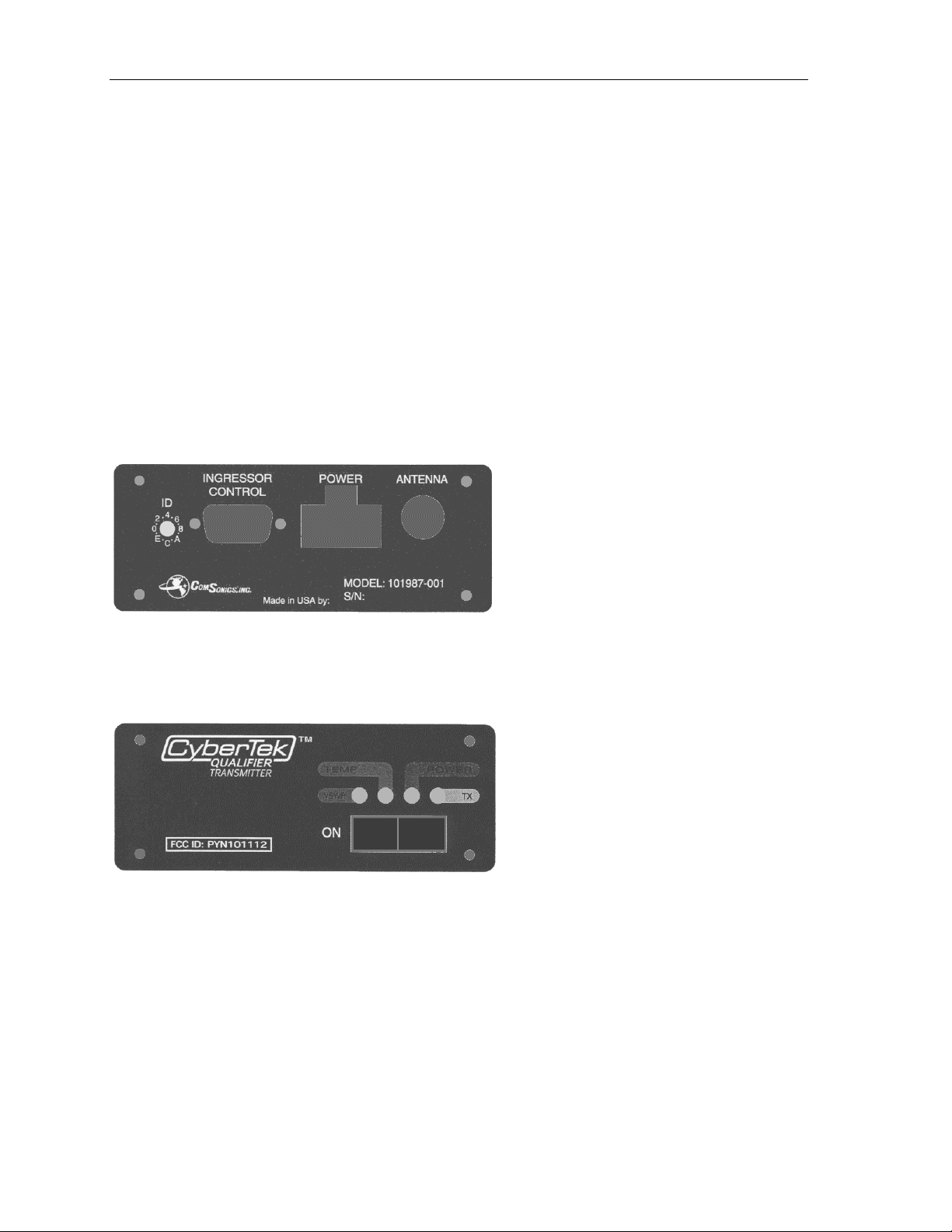
Transmitter
The transmitter unit is mounted in the van (guidelines should be referenced here) and
connected to the antenna. Place the antenna on top of the van or truck preferably in the
center of the roof of the vehicle. When transmitting, the unit will send a series of carrier
bursts at the factory set frequency (27.45, 27.47, 27.49 MHz) radiated at 5W through the
antenna. If the bursts ingress into the house, the Qualifier unit will measure the signal, then
display its relevance to the internal threshold (See Qualifier component).
The transmitter is controlled by the Qualifier via the means of a Command Link, which is
activated when the “Q” is pressed after putting the Qualifier unit in Qualifier Mode. This
allows the Qualifier unit to command the transmitter when to send its carrier.
Elements of the transmitter device are:
Receiver User Identifier (RUID) Rotary Switch
The RUID Rotary switch has 0-F possible values. This allows a transmitter to transmit only
from Qualifier units that send this RUID in the command link transmission. This would
allow more than one transmitter and Qualifier units to service a neighborhood without
interference from one another.
Power Light (Green)
After powering the transmitter, this light will illuminate after the unit has finished internal
initialization and determined that no current fault modes are active. If a current fault is
active, this light will not illuminate.
TX Light (Yellow)
When the unit receives a command from a Qualifier unit to transmit, this light will activate
during the transmission to confirm the Command Link is functional and a signal has been
radiated.
2
Page 7

Qualifier Supplement
VSWR Light (Red)
This light activates when there is an improperly matched antenna. This will only occur when
you try to transmit a signal. To correct, the technician must cycle the power and make an
adjustment to the antenna.
Temperature Light (Red)
This light will activate when the internal temperature exceeds the operating limits. The
device will shutdown in this condition and will not function until an acceptable temperature
range has been reached.
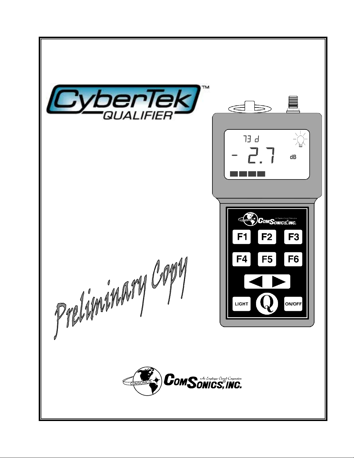
Qualifier Receiver
The Qualifier includes the same functions that are present
in a ComSonics Installer Digital unit. The device also has a
Qualifier Mode that is activated by pressing the “Q” button
on the device. Once in this mode the following keys are
active:
“Q” Key
Pressing this key when in Qualifier Mode enables the
Command Link to a qualifying transmitter. The device will
command the transmitter to send a burst of carriers in order
to make a measurement. If the Qualifier unit detects the
carriers, it will measure the signal strength and display that
measurement relative to the internal threshold set. For
example if the signal is 3 dB below the threshold, -3.0 dB
will be displayed on the unit.
F1 Key (Automatic or Manual)
This key selects between using an Automatic
Threshold (“A”) or Manual Threshold (“M”).
This determines which threshold will be used
when making the qualifying measurements.
Automatic – At the factory the device
threshold will be initialized to a default factory
value (12 dBmV). Each subsequent
measurement will be used in a rolling average to tailor the unit to the cable system’s typical
noise level. The threshold can be reset back to the factory default at any time by pressing the
F2 Key.
d
B
B
B
3
Page 8

Qualifier Supplement
Manual – The user can set a threshold between 2-22 dBmV using the F3 Key and the arrow
keys.
F2 Key (Automatic Reset)
This key will reset the Automatic Threshold
back to the factory default and reinitialize the
rolling average.
B
B
d
B
F3 Key (Manual)
This key will display the current manual
threshold (initialized at the factory at 12
dBmV). The user can then use the Arrow keys
(< or >) to change the value. The range of values are between 2-20 dBmV. Pressing the F6
key will take the unit back into the Main Qualifier Mode.
F4 Key (RUID)
Pressing this key will allow the user to set the Receiver User Identifier (RUID). The current
setting will be displayed. The user can then use the Arrow keys ( < or > ) to change the ID.
Valid ranges are 0-F. Pressing the F6 key will take the unit back into the Main Qualifier
Mode. Note: Qualifier and transmitters used in conjunction need to have the RUID
number match in order for the Qualifier functions to work properly.
F6 Key
Pressing this key will exit Qualifier Mode back
into normal operation. If the user was setting a
Manual threshold or the RUID, the unit goes
back to the main Qualifier Mode display.
d
B
B
B
4
Page 9

Hardware Installation
Install Transmitter
Mount Transmitter
Vehicular Device
Consists of:
Vehicular Mounted Receiver/Transmitter
Mount in an environmentally protected area of the vehicle
Mount with visibility to LED indicators
Receiver/Transmitter Powers from Vehicle
Transmitter produces output signal with unique signature
Transmitter can be factory set to one of three FCC approved frequencies
Transmitter switches between three fixed output power settings as controlled by the
receiver section and commanded by the handheld device
Receiver section receives commands from handheld device
Turn transmitter on / off
Select transmitter output power
Qualifier Supplement
Power Transmitter
Wiring Harness for Receiver/Transmitter
Connect harness to battery of vehicle
Harness contains protection fuse
Maintain proper fuse rating
Protect harness from nicks, pinches, chaffing, damage.
Install Antenna
Mount Antenna
Route Antenna Cable
Vehicular Magnetic Mount Dual Band Antenna
50 ohm cable permanently connected to antenna
BNC connector to receiver/transmitter
Protect antenna cable from nicks, pinches, chaffing, damage
Place antenna in center of vehicle roof, clear of metallic objects
Metallic objects on vehicle roof may cause improper operation of the system
5
Page 10

Qualifier Supplement
Theory of Operation
CATV Distribution System
Local Tap
Downstream Path
Upstream Path
Typical CATV overhead routing to private residence.
Drop Cable
Private Residence
Ground Block
A cable television system distributes signals by a cable suspended on utility poles or by a
cable buried in the ground. A combination of both methods is not uncommon. From the
main distribution cable, a device called a local tap is used to interface the distribution system
cable to the subscriber. From one to eight and possibly more subscribers may be served from
a single local tap location. A multitude of local taps is used through out the distribution
system to provide cable services to subscribers.
From the local tap in overhead systems a drop cable is suspended from the local tap and
secured to the residence at a safe distance from the ground. The drop cable is routed down
the side of the residence to a device called a ground block. The ground block is a pass
through device connected to an earth ground. It is used to prevent static build up between the
cable system and the electrical power wiring of the residence. Thereby reducing the risk of
electrical damage to devices within the residence that are connected to cable system.
From the ground block the cable enters the residence and is routed to the device/s within the
residence. The cable within the residence may be split (branched) into a multitude of paths
supplying cable services to many locations within the residence. Examples of devices
connected to the internal cabling are television sets, VCRs, cable modems, digital carrier
receivers, and special service transceivers.
6
Page 11

Qualifier Supplement
p
Private Residence
Underground
CATV Pedestal
Downstream Path
Upstream Path
CATV Pedestal
with Local Ta
Typical CATV underground routing to private residence.
Drop Cable
Ground Block
The underground distribution system has the cable buried in the ground. The cable only
surfaces into above ground enclosures call pedestals. Opening a pedestal allows access to
the cable system for maintenance. Distribution pedestals contain local taps and an
underground cable is used to supply cable services to the residence. The underground drop
cable usually surfaces just below the ground block.
Cable signals coming to the residence follow the downstream path. Downstream signals are
in the 50 MHz to 1 GHz frequency range. To enable two way communications on a cable
system, the upstream path is used for signals originating within the residence and traveling
to a central location in the cable system. Upstream signals utilize the frequency range of 5 to
50 MHz. The upstream path is used for devices such as cable modems and special services
devices. Examples of special service devices are burglar alarms, fire alarms, and personal
health monitors.
Unfortunately, the reliability of the upstream path is vulnerable to the effects from devices
that radiate electrical energy in the 5 to 50 MHz frequency range. The upstream path uses
digital signals and as such is subject to very unreliable operation if interference signals find
their way into the system. Examples of devices capable of causing interference are: CB
radios, hair dryers, washing machines, food mixers, toasters, vacuum cleaners, and almost
any home appliance that has a motor or a power switch. The interference effect may be for
an instant or continuous while the device is on.
Quality CATV cabling practices utilized within the residence usually reduce or eliminate the
susceptibility of interfering signal ingress.
Ingress problems in the upstream path are compounded by the multitude of residences
connected to the CATV distribution system. Any one residence is capable of adding an
interference signal on the upstream path and inhibiting communications. A multitude of
residences, each only adding only a small amount of interference, can also render the
upstream path useless. Interference signals add on a power basis.
7
Page 12

Qualifier Supplement
The CATV cabling inside a residence is usually hidden in areas such as craw spaces, behind
walls, attics, and basements. The effects of aging on the cable (especially metal connectors),
rodent damage, and possibly improper installation reduce the shielding integrity of the
system within the residence. Poor shielding integrity allows the inside cabling to become a
receiving antenna for interfering signals. A signal or noise entering (ingress) the internal
cabling has the possibility of traveling to the upstream path and causing problems.
Since all residences have the potential to cause problems in the upstream path, a test is
needed to qualify each individual residence. If the internal cabling is susceptible to ingress
from devices within the residence, then it will also have ingress from a known signal source.
The known signal source is a mobile transmitter operating on a frequency in the 5 to 50
MHz range. The mobile transmitter is usually mounted in a service vehicle and powered
from the vehicle. The mobile transmitter also has a feature of variable power output. An
omni-directional antenna is connected to the transmitter and mounted on the vehicle. The
antenna is best mounted on the vehicle roof in an area clear of other metallic objects such as
other antennas, ladders, and lifting apparatus. The vehicle is parked adjacent to the dwelling
(within 100 feet) and the transmitter is powered on. The residence is radiated with the test
signal. Test signal frequency should be chosen as not to cause interference with known
upstream communications.
8
Page 13

Qualifier Supplement
To qualify the shielding integrity of the cabling within the residence, the drop cable is
disconnected from the ground block. A precision receiver is connected to the ground block
(to the connection the drop cable was removed from) with a length of quality jumper cable.
The receiver is tuned to the frequency of the transmitter and measures the level of test signal
being received by the internal cabling. The level of the received test signal is compared to a
reference standard to determine if the shielding integrity of the cabling within the residence
is acceptable. Test signal level measurements may be indicated by the receiver in common
units of measurement, such as µV or dBmV. The receiver may automatically perform the
level comparison function and produce a Pass/Fail message. If the measured level of the test
signal is greater than acceptable limits, each routing of the internal system may be tested
individually to determine the fault. Usually a CATV signal splitter is located in close
proximity to the ground block. Disconnecting individual cables from the splitter and
retesting allows for insolating the faulty routing.
9
Page 14

Qualifier Supplement
A further test involves testing the drop cable section of the residential system. The drop
cable is disconnected from the ground block and the drop cable is connected to the precision
receiver. With the mobile transmitter powered on and the receiver tuned to the frequency of
the transmitter, the level of test signal is measured. The level of the received test signal is
compared to a reference standard to determine if the shielding integrity of the drop cable is
acceptable. Test signal level measurements may be indicated by the receiver in common
units of measurement, such as µV or dBmV. The receiver may automatically perform the
level comparison function and produce a Pass/Fail message. A greater than acceptable level
measurement would most likely indicate a faulty connection at the local tap.
10
Page 15

Transmitter Antenna
Qualifier Supplement
Activate
Signal
An enhancement to the integrity (ingress) test system is the function of the receiver
activating the transmitter only when measurements need to be made. Thereby reducing
vehicle power drain, transmitter heating, and general RF pollution. Additionally, the
activation signal from the receiver is encoded and the transmitter recognizes the encoded
activation signal. In this manner, false transmitter activation is eliminated. A multitude of
activation codes is available allowing multiple test systems to be in operation in the same
vicinity. Only the transmitter associated with a given receiver code activates when needed.
In practice the transmitter and activate antennas can be combined into one dual band antenna
with a diplex filter at the transmitter/receiver.
A further enhancement is the coding of the transmitter signal. In this manner, the receiver
can reject measurements not recognized as those from the test transmitter.
Other enhancements include: measurement data storage within the receiver for later retrieval
and analysis, integration with GPS system for location and time data, integration with a
cable modem or wireless device for data transfer to a central CATV location or internet
access.
11
Page 16

Qualifier Supplement
Transmitter Block Diagram
Dual Band Antenna
Test Signal
Transmitter
Diplex Filter
Activation
Receiver
Transmitter
Enable
Switch
Activation
Decoder
Power
Input
The transmitter is mounted in and powered from a vehicle. The antenna is mounted on the
vehicle’s roof. Preferably placed in a location free of other metallic objects. The dual band
antenna receives a properly coded activation signal from a receiver. The diplex filter routes
the activation signal to the activation receiver. The activation decoder determines a code
match between the received signal and setting of the transmitter. If a code match occurs, the
decoder activates the transmitter enable switch. Otherwise the transmitter remains powered
off. The transmitter enable switch causes the transmitter to power on. The test signal is feed
to the dual band antenna by the diplex filter. The diplex filter prevents the test signal from
being routed to the activation receiver.
12
Page 17

Receiver Block Diagram
Internal Activate Antenna
Qualifier Supplement
Test Signal
Connection
Activate
Transmitter
Input Tuner
Section
User
Interface
Activate
Encoder
Test Signal
Detector
Data
Memory
Battery
Power
Display
Converter
Visual
Display
The precision receiver is powered by an internal battery and is portable in design.
A test sequence consists of the following steps.
Receiver is connected to ground block of residence under test.
User interface powers on the activate encoder. The activate encoder has been previously
setup to match the intended vehicle transmitter. The activate transmitter is powered on and
the activate signal is radiated from the internal antenna.
The vehicle transmitter receives the activation signal and verifies the coding. If the coding
matches, the vehicle transmitter powers on and radiates the residence with the test signal.
The input tuner section receives the test signal resulting from ingress into the residence. The
test signal detector qualifies the test signal as originating from the test transmitter. If the test
signal qualifies, the display converter sends the level measurements to the visual display. If
the receiver is configured as such, a Pass / Fail message is displayed.
Measurement data is stored to data memory by the user interface.
13
Page 18

Page 19

 Loading...