

Page 1
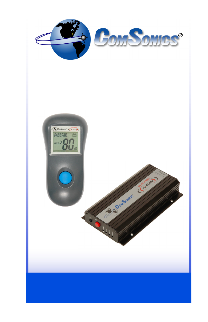
Qualifier X-Ray
Non-Intrusive
Dwelling Ingress Integrity
Measurement System
USER GUIDE
CSI Doc. 101399-001
Page 2

Qualifier X-Ray
Limited Warranty
Hardware: ComSonics, Inc. (ComSonics) warrants to the original end user
(Customer) that the new ComSonics branded products will be free from defects in
workmanship and materials, under normal use, for one (1) year from the date of
original shipment. ComSonics warrants repaired and refurbished ComSonics
products for ninety (90) days from date of shipment.
Agency Notice
Hand Held Device Vehicle Mounted Device
FCC ID: PYN2007HHD FCC ID: PYN2007VMD
IC: 4261A-2007HHD IC: 4261A-2007VMD
Complete Limited Warranty and Agency Notice documentation is printed in the
back section of this user guide.
(brief)
(brief)
Technical Support
ComSonics maintains a Technical Support Service for customer convenience.
Contact a Support Representative at 1-800-336-9681 or 1-540-434-5965;
Fax 1-540-432-9794; or Email tech-support@comsonics.com.
Copyright
All material in this manual is the property of ComSonics, Inc. and protected under
the United States copyright law. No material shall be reproduced or used in any
form or by any means (graphic, electronic, or mechanical, including photocopying,
recording, taping, or information storage and retrieval systems) without the written
permission of:
Harrisonburg, Virginia 22801 USA
Phone: (540) 434-5965 USA Toll Free: (800) 336-9681
Email: marketing@comsonics.com
Qualifier is a trademark of ComSonics, Inc.
2007 ComSonics, Inc. All Rights Reserved
ComSonics, Inc.
1350 Port Republic Road
Post Office Box 1106
Fax: (540) 434-9847
Internet: www.comsonics.com
CSI Doc. 101399-001 Rev. 1.05
sh
i
1 - 8 0 0 - 3 3 6 - 9 6 8 1
Page 3

Table of Contents
Introduction.......................................................................................................1
FCC License Requirement ...........................................................................1
Unpacking ....................................................................................................1
Qualifier X-Ray System Overview ................................................................2
General Information..........................................................................................3
Hand Held Device (HHD) .............................................................................3
Battery Installation .................................................................................3
Single Button Control.............................................................................3
Auto Power Off ......................................................................................3
Display Screen.......................................................................................4
Threshold Value Setup ..........................................................................4
Hardware Installation ...................................................................................6
Dual Band Antenna................................................................................7
Vehicle Mount Device (VMD).................................................................7
Check / Select Transmit Frequency.......................................................8
Test the VMD Installation.......................................................................8
Qualifier System Installation Verification......................................................9
Troubleshooting Notes .................................................................................9
Using the Qualifier X-Ray System.................................................................10
Dwelling Shielding Integrity Measurement Procedure ...............................10
Specifications .................................................................................................11
Accessories / Parts.........................................................................................12
Warranty Statement........................................................................................13
Agency Notice.................................................................................................15
w w w . c o m s o n i c s . c o m
ii
Page 4
Qualifier X-Ray
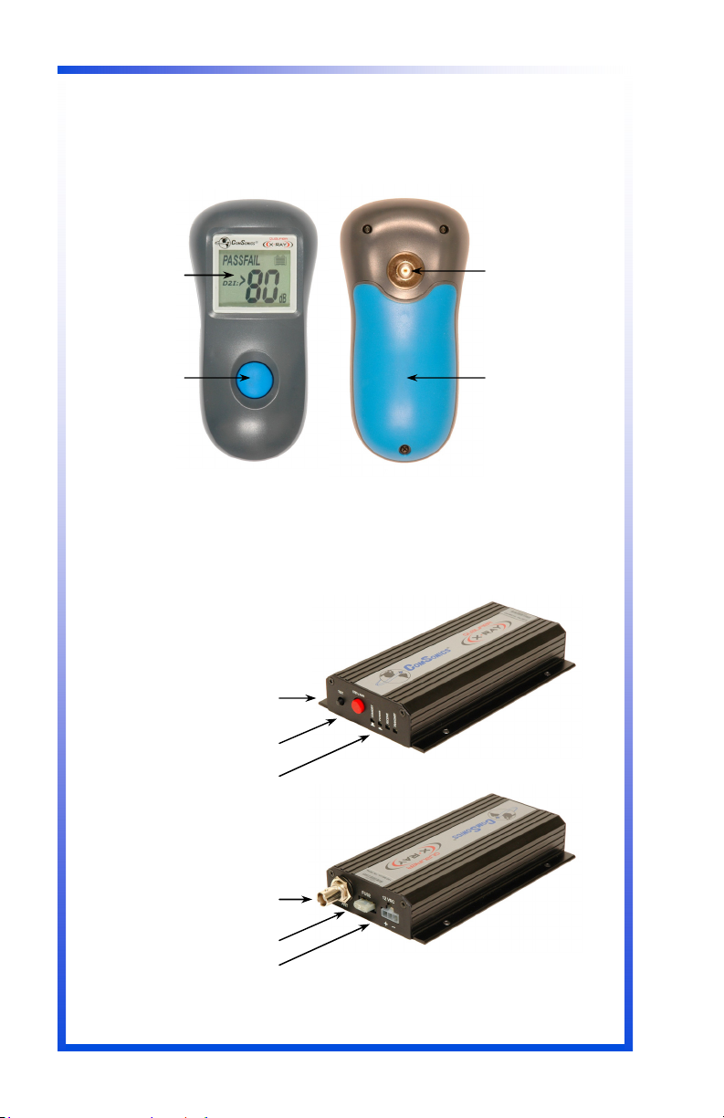
Major Components
Display
Screen
Power / Test
Button
Test Button
Power Button
Status Indicators
Antenna Connector
Power Harness Connector
Input
Connector
Battery
Compartment
Fuse
iii
1 - 8 0 0 - 3 3 6 - 9 6 8 1
Page 5
Introduction
FCC License Requirement
A FCC license is required to operate the Qualifier X-Ray System, specifically the
vehicle mount transmitter component (VMD).
Refer to the Qualifier Transmitter Licensing section on our website at
www.comsonics.com/downloads.html for application instructions and templates.
If you need assistance, please call our Customer Service Department at 1-800336-9681.
Unpacking
The Qualifier X-Ray System and accessories are shipped in a single container
designed to provide maximum protection during transit. Immediately upon receipt,
inspect the container and contents for signs of physical damage. Notify the freight
forwarder of any damage detected.
Installation Caution!
The Qualifier X-Ray System is designed only for vehicles equipped with a 12-volt
negative ground electrical system.
w w w . c o m s o n i c s . c o m
1
Page 6

Qualifier X-Ray
Qualifier X-Ray System Overview
The ComSonics Qualifier X-Ray System provides a method for identifying the
internal shielding integrity of the CATV network in a subscriber’s residence without
the need to enter the premises.
A test activation transmitter is located within the Qualifier hand held device (HHD).
The transmitter provides an activation signal to the Qualifier Vehicle Mounted
Device (VMD) and sets up the HHD to measure levels of ingress from the VMD
signal appearing in the return upstream path.
With the HHD connected to either the residential ground block or the drop tap, a
press of the HHD button activates the VMD to generate a brief 5-watt signal pulse
at a frequency, just above the CB radio band, within the upstream frequency spectrum.
The VMD test signal envelopes the residence with a level of about +58 dBmV
(assuming the service vehicle is about 75 feet from the residence). Shielding
flaws, within the residential cabling, allow the VMD signal to enter the return upstream path. The HHD detects the VMD test signal and displays a shielding integrity value based on the ingress level measured.
The threshold setup function in the HHD determines the indication of PASS or
FAIL with the integrity measurement.
Shielding Integrity Measurement
The Qualifier X-Ray System utilizes a unique measurement method to determine
the relative shielding integrity of a customer premise without a need to enter the
structure. This method provides the user with a numeric display representing a
calculated shielding factor, in dB, of the premise under test.
The type of flexible coaxial cable used for drops and house wiring typically has a
shielding integrity factor in the range of 60 to 80 dB. But with the addition of connectors, splitters, VCRs, televisions, PC modems, and other devices along with
improper installation techniques; the total overall shielding integrity can degrade
appreciably. The possibility of noise ingress (undesirable signals) increases
greatly if the shielding integrity is not sufficient. Noise ingress causes interference
with the return path signals and reduces the reliability of two-way signal communications.
The Qualifier X-Ray System enables the user to obtain a shielding integrity reading in the range of 80 dB (very good) to 25 dB (very poor). Each measurement
reading includes a PASS or FAIL indication, based on a user selectable threshold
value, for easy measurement status determination. The threshold function can be
turned off.
Formula for calculating the shielding integrity reading:
D2I = Pmax [+85] - (antenna gain [2.5] + free space loss [25]) - measured value
*D2I is the acronym for Dwelling Ingress Integrity
2
1 - 8 0 0 - 3 3 6 - 9 6 8 1
Page 7

General Information
Hand Held Device
The Hand Held Device (HHD) is a small pocket size unit containing the test activation transmitter and the ingress test signal
receiver.
Battery Installation
The HHD is powered by three standard AAA alkaline batteries.
To install the batteries, loosen the battery compartment screw
and remove the cover. Install the batteries, all three with the
positive end in the same direction, as indicated. Replace the
cover and tighten the screw. Use care not to over tighten the
screw.
Be sure to recycle or properly dispose of old batteries.
The HHD automatically powers off when the battery condition
is low to protect the batteries from excessive discharge and
possible leakage. Periodically remove the battery cover and
inspect the batteries for signs of leakage.
Caution: Do not store the HHD for extended periods of time
with the batteries installed. Failures due to battery leakage are
not covered under warranty.
Single Button Control
The HHD is controlled by one multi-function button.
To power the HHD on:
Press and hold the Button for one second.
To activate an integrity measurement cycle:
Press the Button once.
This also resets the back light and power auto-off timers.
To access the PASS/FALL threshold setup mode:
Press the Button twice within one second.
Press the Button to set the threshold level.
To power the HHD off:
Press and hold the Button for one second.
Auto Power Off
The HHD automatically powers off sixteen seconds after the last Button press.
The back light turns off in six seconds and the HHD powers off ten seconds later.
Cover
Screw
w w w . c o m s o n i c s . c o m
3
Page 8

Qualifier X-Ray
Display Screen
The Display screen provides information on the
battery condition, units of measure, shielding
integrity value, and if enabled, the PASS/FAIL
status of the measurement. A back light illuminates the display.
Battery Level
A fresh set of batteries is indicated by four bars.
Each bar represents approximately 25% runtime
capacity. A low battery condition is indicated by
no bars showing. The HHD automatically powers off when the battery state is low.
Note: The accuracy of the battery level indicator is relative and will vary with the
battery type and manufacturer.
Shielding Integrity Measurement Value
When a measurement is made, by a single press of the Button, the level of the
ingress signal is displayed as a shielding integrity value in dB units-of-measure.
The value range is 80 dB (very good shielding) to 25 dB (very poor shielding).
PASS / FAIL Function
The HHD can be setup with a measurement threshold value to determine if the
integrity reading is acceptable. PASS is displayed if the measured integrity value
is higher (better) than the threshold value. FAIL is displayed if the measured integrity value is lower (worse) than the threshold value. The PASS/FAIL threshold
value is user selectable. This function can be disabled as described on the next
page.
Threshold Value Setup
To access the threshold value setup mode, press the Button twice within one
second when the HHD is on. The PASSFAIL readout activates and two digits
display the current threshold value. Press and hold the Button to scroll to the desired threshold value. Release the Button to stop rapid scrolling and then use
single presses of the Button to the desired value. If a lesser value is desired, continue to hold the Button as the value wraps around from 80 and then back down to
25 dB. Release the Button and allow the HHD to auto power off (six seconds). At
the next power up, the newly set threshold value is enabled and the PASS or the
FAIL indicator will display accordingly. See the next sections for the procedure to
disable or enable the PASS / FAIL function.
4
1 - 8 0 0 - 3 3 6 - 9 6 8 1
Page 9

Disable the PASS / FAIL Function
The HHD PASS / FAIL function can be disabled by setting the threshold value to
80 dB. In this mode, neither the PASS nor the FAIL indicator appears.
Enable the PASS / FAIL Function
To enable the HHD PASS / FAIL function, set the threshold value to a setting
other than 80 dB.
Test Signal Verification
The combined PASSFAIL label is displayed along with the integrity reading if the
HHD is unable to clearly receive the VMD test signal. The HHD performs a pretest
signal level measurement prior to triggering the VMD and then compares that
level with the measurement made during the VMD transmit interval. If the VMD
signal level is no greater than the pretest level, then the combined PASSFAIL
label is shown. The test signal verification function is not affected by disabling the
Threshold function.
w w w . c o m s o n i c s . c o m
5
Page 10

Qualifier X-Ray
Vehicle Hardware Installation
Vehicle Mount Device (VMD)
The Qualifier X-Ray system requires installation of the Qualifier Vehicle Mounted
Device (VMD) and a Dual Band Antenna.
Installation Precautions
Please observe the following during installation.
Wear eye protection when installing the system.
The vehicle must have a 12-volt negative ground electrical system.
Insure that no mounting hardware makes contact with any wiring, fuel/brake
lines or other components.
Insure the mounting position of the VMD is clear of obstacles.
Protect the system from metal debris.
Do not route cabling or wiring through sharp edged openings or potential
pinch points to prevent future failures and safety hazards.
Maintain at least one inch of clearance around the VMD for proper cooling.
6
1 - 8 0 0 - 3 3 6 - 9 6 8 1
Page 11

Install the Antenna
Install the Vehicle Mounted Device (VMD)
Check the hardware in your Qualifier
VMD Installation Kit (part number
101488-001) to the illustration.
Four screws
Power cable
Use the hardware contained in the kit to install the VMD as follows:
Place the VMD over the selected mounting location. Allow at least a two inch
clearance beyond the rear panel for installation of cables. Mark the location of the
four mounting holes using a center punch. Alternate mounting methods may be
required in certain installations.
Protect the VMD from debris and use a 1/4-inch nut driver attached to a power
screwdriver or variable speed drill to install four (4) one-inch self-drilling screws.
DO NOT OVER TIGHTEN THE SCREWS! Remove any debris remaining from the
drilling operation.
Connect the antenna cable to the VMD.
Place the Magnetic Mount Dual Band Antenna on a
flat roof surface of the vehicle. Position it near as
possible to the center of the roof away from nearby
metallic objects; such as other antennas, booms, or
ladders. Route the cable, perpendicular to the centerline of the roof, to the point where the antenna cable
enters the vehicle. Use caution to prevent damage to
the cable. Coil any excess cable in a loose loop inside
the vehicle. Secure the cable as needed.
Note: Periodically remove the antenna and clean dust
and grit from the vehicle surface and bottom of the
antenna to reduce abrasion to the vehicle finish.
Route the
antenna
cable to
side of
vehicle.
w w w . c o m s o n i c s . c o m
7
Page 12

Qualifier X-Ray
Install the VMD Power Harness
Connect the RED lead to the vehicle (+12V) ignition or accessory fuse block circuit. Connect the BLACK lead to the vehicle ground. A 2-ampere safety fuse is
used in the red lead.
Connect the power harness to the VMD.
The red Standby indicator is on with power applied and the VMD Power Switch
set to OFF.
Check / Select the VMD Transmit Frequency
Push the VMD power switch to the ON position; wait a few seconds for the VMD
to initialize, and the green Power indicator to illuminate. Then, press and hold the
Test button for 2 seconds. The orange Receive indicator flashes showing the
operating frequency by the following patterns:
One flash and a pause frequency 1 = 27.45 MHz
Two flashes and a pause frequency 2 = 27.47 MHz (factory default)
Three flashes and a pause frequency 3 = 27.49 MHz
To select a different transmit frequency while a code is flashing; press the Test
button to step to the next frequency. The frequency select sequence wraps
around from frequency 3 back to frequency 1.
The VMD returns to normal operating mode after the indicator flashes the code
sequence for 10 seconds. The selected operating frequency is retained regardless
of powering conditions.
In accordance with FCC License requirements, the operating frequency may need
to be changed. Refer to the Qualifier Transmitter Licensing section on our website at ‘www.comsonics.com/downloads.html’ for application instructions and templates.
Test the VMD Installation
Push the VMD power switch to the ON position and wait a few seconds for the
VMD to initialize. Momentarily press the Test button and the yellow Transmit indicator comes on for a few seconds as the VMD generates the output power signal
to the antenna.
Warning: The Dual Band Antenna must be properly mounted on the vehicle and
connected to the VMD before performing this test or operating the Qualifier system. Improper operation of the system may result in permanent damage to the
VMD and is not covered under warranty.
8
1 - 8 0 0 - 3 3 6 - 9 6 8 1
Page 13

Qualifier System Installation Verification
1. Power-on the VMD and wait a few seconds for it to initialize.
2. On the HHD, connect a ≈ 2 inch stub antenna to the BNC connector.
(Example: Use a straightened paperclip inserted into a BNC-to-F adapter.)
Make sure the HHD batteries are fresh.
3. Stand about 10 feet from the vehicle and hold the
HHD with a vertical orientation of the stub antenna.
4. Power on the HHD and then press the Button.
5. The VMD orange Receive indicator flashes once
and then the yellow Transmit indicator comes on for
a moment.
6. The HHD displays ‘ - - dB’ briefly and then shows a
reading between 25 and 80 dB.
Note: If the HHD shows ‘> 80 dB’ and the
‘PASSFAIL’ label, check the Dual Band Antenna
connection and repeat the ‘Test the VMD Installation’ procedure.
7. Set the HHD Threshold to a value less than the
displayed reading.
8. Repeat the test and note that PASS is displayed.
9. Set the HHD Threshold to a value greater than the
displayed reading.
10. Repeat the test and note that FAIL is displayed.
11. Set the HHD Threshold Level to 80 dB.
12. Repeat the test and note that neither PASS nor FAIL is displayed.
13. Reset the HHD Threshold to a value for system test operation.
Troubleshooting Notes:
If the trigger signal from the HHD is marginal, the VMD orange Receive indicator
flashes several times and the yellow Transmit indicator does not come on.
If the VMD is triggered by the HHD and the orange Receive indicator flashes once
(as normal) but the yellow Transmit indicator does not come on, there is a problem with the antenna or the internal transmitter section of the VMD.
If the TEST button on the VMD is pressed momentarily and the yellow Transmit
indicator does not come on, there is a problem with the antenna or the internal
transmitter section of the VMD.
The reliability of the HHD triggering the VMD may be reduced in these test location scenarios:
The elevation of the HHD test location is significantly lower than the VMD
vehicle antenna.
The residence under test, located between the HHD and the VMD vehicle,
significantly blocks or absorbs the HHD trigger signal.
Initial Power On
Measurement in Process
w w w . c o m s o n i c s . c o m
9
Page 14

Qualifier X-Ray
Using the Qualifier X-Ray System
Residential Shielding Integrity Measurement Procedure:
1. Locate the Qualifier VMD equipped vehicle about 50 to 75 feet from the test
residence.
2. Set the VMD power switch to ON.
3. Disconnect the CATV drop cable from the residence ground block or splitter.
As an alternative method, disconnect and test at the tap or pedestal.
4. Use a BNC-to-F adapter and a short jumper cable to connect the Qualifier
HHD to the open residential terminal. If using the tap or pedestal method, connect the HHD to the free end of the drop cable. If needed, use a quality extension cable and a F-81 barrel. Tighten connections as needed.
5. Power on the HHD.
6. Press the HHD Button to activate the measurement
sequence.
7. The HHD displays ‘- - dB’ briefly and then shows the
shielding integrity reading. PASS or FAIL may also be
displayed, based on the Threshold value setting.
8. Repeat the measurement sequence a second time to
insure the reading.
For a low integrity reading from a tap or pedestal
location, retest from the residence ground block or
splitter location.
For a low integrity reading when connected to the
input of the residential splitter, disconnect each cable from the splitter output (one at a time) and retest
to determine the path of ingress.
If the PASSFAIL label appears, the indication of not
clearly receiving the VMD test signal, check the HHD
connection and the VMD operation. Integrity readings in the range of 25 to 80 with the PASSFAIL
label showing may indicate excessive noise signals.
9. Disconnect the HHD jumper cable and reconnect the drop cable.
10.Weather-proof the connection as needed.
Initial Power On
Measurement in Process
10
1 - 8 0 0 - 3 3 6 - 9 6 8 1
Page 15

Specifications
Hand Held Device (HHD)
Operational Control
Input Frequency Range
Input Level Range
Integrity Measurement Range 25 to 80 dB (shielding effectiveness)
Accuracy
Threshold Function Range
Power Source
Custom Display
Auto Power Off
Size
Weight
Operating Temperature
Storage Temperature
Humidity
Vehicle Mount Device (VMD) (FCC license required)
Output Frequency
Output Power
User Controls
Indicators
Power Source
Size
Mounting
Operating Temperature
Storage Temperature
Humidity
(User Selectable)
Single Button
27.45 to 27.49 MHz
-30 to +30 dBmV
± 2.0 dB (input level to converted reading)
25 to 79 dB (user selectable, 80 disable)
AAA Alkaline x 3 cells
1.2” x 1.5”
16 seconds
5.5” x 2.5” x 1.75”
0.5 lbs
0ºF to 120ºF
-20ºF to 150ºF
Moderate Rainfall
(30 mm x 39 mm),
(0.23 kg)
(-18ºC to 49ºC)
(-29ºC to 66ºC)
with backlight
(140mm x 64mm x 44 mm)
27.45 MHz, 27.47 MHz*, or 27.49 MHz
5 Watts, EIRP
Power On/Off and Test/Output Frequency
Standby, Power, Receive, and Transmit
12 VDC negative ground, < 12 Watts
6” x 3.5” x 1” (150 mm x 90 mm x 26 mm),
Fixed
0ºF to 140ºF (-18ºC to 60ºC)
-20ºF to 150ºF (-29ºC to 66ºC)
0 ~ 95% non-condensing
* Factory Default Setting
w w w . c o m s o n i c s . c o m
11
Page 16

Qualifier X-Ray
Accessories / Parts
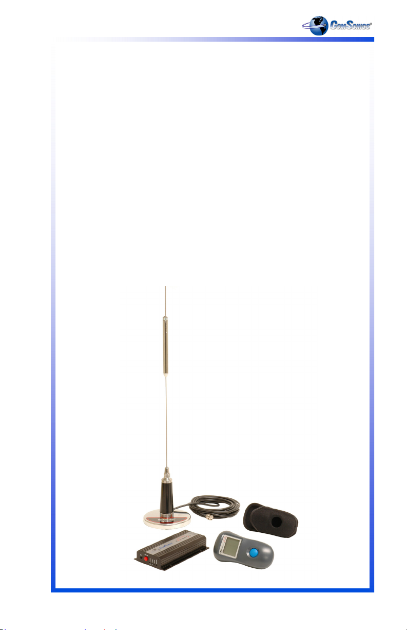
System Package - Qualifier X-Ray Hand Held Device, Holster,
Vehicle Mounted Device, Power Harness, Dual Band Antenna,
and User Guide
Qualifier Hand Held Device (HHD)
Qualifier Vehicle Mounted Device (VMD)
Qualifier Dual Band Vehicle Magnetic Antenna
Holster for Qualifier Hand Held Device (belt clip type)
Power Harness for Qualifier Vehicle Mounted Device
Battery for Qualifier Hand Held Device (3 required)
Qualifier X-Ray User Guide
101396-001SC
101393-001
101396-001
101272-001
101240-001
101488-001
BB-542
101399-001
12
1 - 8 0 0 - 3 3 6 - 9 6 8 1
Page 17

Limited Warranty
Hardware: ComSonics, Inc. (ComSonics) warrants to the original end user
(Customer) that the new ComSonics branded products will be free from defects in
workmanship and materials, under normal use, for one (1) year from the date of
original shipment. ComSonics warrants repaired and refurbished ComSonics
products for ninety (90) days from date of shipment.
Exclusions
This warranty excludes:
Damage to the physical surface of the product, including cracks or
scratches to any part.
Damage caused by misuse, neglect, improper installation or testing, un-
authorized attempts to open, repair, or modify the product, or any other
cause beyond the range of the intended use.
Damage caused by accident, fire, power changes, other hazards, or acts
of nature.
Use of the product with any non-recommended device or service if such
device or service causes the problem.
Any third party products, including software, included with ComSonics products
are not covered by this ComSonics warranty and ComSonics makes no representations or warranties on behalf of such third parties. Any warranty on such products is from the supplier or licensor of the product.
Exclusive Remedies
Should a covered defect occur during the warranty period and you notify ComSonics, your sole and exclusive remedy shall be, at ComSonics sole option and
expense, to repair or replace the product. If ComSonics cannot reasonably repair
or replace then ComSonics may, in its sole discretion, refund the purchase price
paid for the product. Replacement products or parts may be new or reconditioned
or comparable versions of the defective item. ComSonics warrants any replaced
or repaired product, or part for a period of ninety (90) days from shipment, or
through the end of the original warranty, whichever is longer.
Obtaining Warranty Service: Customer must contact ComSonics Technical
Support or Customer Service within the applicable warranty period. Products or
parts shipped by Customer to ComSonics must be sent postage-paid and packaged appropriately for safe shipment. ComSonics is not responsible for damage
occurring in transit from Customer to ComSonics. Repaired or replacement products will be shipped to Customer at ComSonics’ expense. All products or parts
that are replaced become the property of ComSonics. ComSonics shall not be
responsible for Customer’s software, firmware, information, or memory data contained in, stored on, or integrated with any products returned to ComSonics for
repair, whether under warranty or not.
w w w . c o m s o n i c s . c o m
13
Page 18

Qualifier X-Ray
WARRANTIES EXCLUSIVE: THE FOREGOING WARRANTIES AND REMEDIES ARE EXCLUSIVE AND IN LIEU OF ALL OTHER WARRANTIES, EXPRESS OR IMPLIED, INCLUDING WARRANTIES OF MERCHANTABILITY,
FITNESS FOR A PARTICULAR PURPOSE, CORRESPONDENCE WITH DESCRIPTION, AND NON-INFRINGEMENT, ALL OF WHICH ARE EXPRESSLY
DISCLAIMED BY COMSONICS AND ITS SUPPLIERS.
LIMITATION OF LIABILITY: NEITHER COMSONICS NOR ITS SUPPLIERS
SHALL BE LIABLE FOR INCIDENTAL, CONSEQUENTIAL, INDIRECT, SPECIAL, OR PUNITIVE DAMAGES OF ANY KIND, LOSS OF INFORMATION OR
DATA, OR OTHER FINANCIAL LOSS ARISING OUT OF OR IN CONNECTION
WITH THE SALE OR USE OF THIS PRODUCT, WHETHER BASED IN CONTRACT, TORT (INCLUDING NEGLIGENCE) OR ANY OTHER THEORY, EVEN
IF COMSONICS HAS BEEN ADVISED OF THE POSSIBILITY OF SUCH DAMAGES. COMSONICS ENTIRE LIABILITY SHALL BE LIMITED TO REPLACEMENT, REPAIR, OR REFUND OF THE PURCHASE PRICE PAID, AT CONSONICS’ OPTION.
Disclaimer: Some countries, states, or provinces do not allow the exclusion or
limitation of implied warranties or the limitation of incidental or consequential damages so the above limitations and exclusions may be limited in their application to
you. When implied warranties may not be excluded their entirety, they will be
limited to the duration of the applicable written warranty. This warranty gives you
specific legal rights; you may have other rights that may vary depending on local
law. Your statutory rights are not affected.
Governing Law: This Limited Warranty shall be governed by the laws of the State
of Virginia, U.S.A., and by the laws of the United States, excluding their conflicts
of laws principles. The United Nations Convention on Contracts for the International Sale of Goods is hereby excluded in its entirety from application to this Limited Warranty.
ComSonics, Inc.
1350 Port Republic Road
Post Office Box 1106
Harrisonburg, Virginia 22801
United States of America
www.comsonics.com
June 1, 2007
14
1 - 8 0 0 - 3 3 6 - 9 6 8 1
Page 19

Agency Notice
FCC Part 15
Qualifier X-Ray, Hand Held Device
FCC ID: PYN2007HHD
This device complies with Part 15 of the FCC Rules. Operation is subject to the
following two conditions: (1) this device may not cause harmful interference, and
(2) this device must accept any interference received, including interference that
may cause undesired operation.
FCC Part 15 for Handheld Devices
To comply with FCC RF exposure requirements, this device must be operated in
the hand with a minimum separation distance of 23 cm or more from a person's
body. Other operating configurations should be avoided.
Note: This equipment has been tested and found to comply with the limits for a
Class A digital device, pursuant to Part 15 of the FCC rules.
These limits are designed to provide reasonable protection against harmful interference in a residential installation. This equipment generates, uses, and can
radiate radio frequency energy. If not installed and used in accordance with the
instructions, the equipment may cause harmful interference to radio communications. Operation of this equipment in a residential area is likely to cause harmful
interference in which case the user will be required to correct the interference at
own expense.
Qualifier X-Ray, Vehicle Mounted Device
FCC ID: PYN2007VMD
FCC Compliance and RF Exposure Information
This product is certified by the FCC as compliant with CFR.47 Part 90.
Changes or modifications not expressly approved by the manufacturer could void
the user's authority to operate the equipment.
Industry Canada
Qualifier X-Ray, Hand Held Device
IC: 4261A-2007HHD
This Class A digital apparatus complies with Canadian ICES-003. Cet appareil
numérique de la Classe A est conforme à la norme NMB-003 du Canada.
Qualifier X-Ray, Vehicle Mounted Device
IC: 4261A-2007VMD
This Class A digital apparatus complies with Canadian ICES-003. Cet appareil
numérique de la Classe A est conforme à la norme NMB-003 du Canada.
The installer of this radio equipment must ensure that the antenna is located or
pointed such that it does not emit RF field in excess of Health Canada limits for
the general population; consult Safety Code 6, obtainable from Health Canada's
website www.hc-sc.gc.ca/rpb.
w w w . c o m s o n i c s . c o m
15
Page 20

Qualifier X-Ray
ComSonics, Inc.
1350 Port Republic Road
Post Office Box 1106
Harrisonburg, Virginia 22801 USA
Phone: (540) 434-5965 USA Toll Free: (800) 336-9681
Fax: (540) 434-9847
Email: marketing@comsonics.com
Internet: www.comsonics.com
2007 ComSonics, Inc. All Rights Reserved
Document No. 101399-001 Rev. 1.05
sh
 Loading...