


H685 User Manual
Industrial Grade 2G 3G 4G Cellular Router
User Manual
H685 Series
E-Lins Technology Co., Limited
PHONE: +86-755-29230581
Email: sales@e-lins.com
WEB: http://www.e-lins.com
ADDRESS: Rm.33, Unit B, Floor 12, U chuanggu, Xinniu Rd,
Minzhi, Longhua, Shenzhen, 518000, China
E-Lins Technology Co.,Limited
Tel: +86-755-29230581 E-mail: sales@e-lins.com www.e-lins.com

H685 User Manual
Content
1 Preparation job before configuration ································································································ ······························· 4
1.1 Learn your router version and feature ································ ················································································· 4
1.2 Prepare SIM Card and working condition ································································ ··········································· 6
1.3 Highly recommendation for the configuration ····································································································· 6
2 Hardware Installation ························································································································································· 6
2.1 Overall Dimension ·················································································································································· 7
2.2 The Ports ································································································ ·································································· 7
2.3 Installment ································································································ ································································ 8
2.4 SIM/UIM card installed ··········································································································································· 9
2.5 The installation of terminal blocks ························································································································ 9
2.6 Grounding ································································································ ······························································ 11
2.7 Power Supply ································································································································ ························ 11
2.8 LED and Check Network Status ························································································································· 11
3 Software configuration ································ ····················································································································· 13
3.1 Overview ································································································ ································································ 13
3.2 How to log into the Router ··································································································································· 14
3.3 Router status ································ ································································································ ························· 17
3.3.1 Status overview ·················································································································································· 17
3.3.2 Network status ································································ ··················································································· 18
3.3.3 Firewall status ···················································································································································· 21
3.3.4 Routes ································································································································································· 21
3.3.5 System log ·························································································································································· 22
3.3.6 Kernel log ···························································································································································· 23
3.3.7 Realtime graphs ················································································································································· 24
3.3.8 VPN ································································································································································ ····· 25
3.4 System Configuration ··········································································································································· 28
3.4.1 Setup wizard ······················································································································································ 28
3.4.2 System ································································································ ································································ 29
3.4.3 Password ···························································································································································· 30
3.4.4 NTP ······································································································································································ 32
3.4.5 Backup/Restore ································································ ················································································· 33
3.4.6 Upgrade ································································································ ······························································ 33
3.4.7 Reset ··································································································································································· 35
3.4.8 Reboot ································································································································································· 35
3.5 Services configuration ·········································································································································· 36
3.5.1 ICMP check ························································································································································ 36
3.5.2 VRRP ·································································································································································· 37
3.5.3 Failover (link backup) ········································································································································ 39
3.5.3.1 Failover basic settings ··································································································································· 39
3.5.3.1 Failover Advanced settings ··························································································································· 40
3.5.4 DTU ································································································································································ ····· 40
3.5.5 SNMP ·································································································································································· 43
E-Lins Technology Co.,Limited
Tel: +86-755-29230581 E-mail: sales@e-lins.com www.e-lins.com

H685 User Manual
3.5.6 GPS ····································································································································································· 45
3.5.7 SMS ····································································································································································· 46
3.5.8 VPN ································································································································································ ····· 57
3.5.8.1 IPSEC ································································································ ······························································ 57
3.5.8.2 PPTP ································································································································································ 60
3.5.8.3 L2TP ································································································································································· 63
3.5.8.4 OpenVPN ································································································ ························································ 66
3.5.8.5 GRE tunnel ································································································································ ······················ 67
3.5.9 DDNS ································································ ································································································ ·· 69
3.5.10 Connect Radio Module ··································································································································· 73
3.6 Network Configuration ········································································································································· 74
3.6.1 Operation Mode ················································································································································· 75
3.6.1.1 Gets two LAN Ethernet Port for H685 ········································································································· 75
3.6.2 Mobile configuration ·········································································································································· 76
3.6.3 Cell mobile data limitation ································ ································································································ 79
3.6.4 LAN settings ······················································································································································· 80
3.6.5 wired-WAN ·························································································································································· 83
3.6.6 WiFi Settings ······················································································································································ 85
3.6.6.1 Wifi General configuration ···························································································································· 86
3.6.6.2 WiFi Advanced Configuration ······················································································································· 86
3.6.6.3 WiFi Interface Configuration ························································································································· 87
3.6.6.4 WiFi AP client ·················································································································································· 89
3.6.7 Interfaces Overview ·········································································································································· 91
3.6.8 Firewall ································································································································································ 92
3.6.8.1 General Settings ············································································································································· 92
3.6.8.2 Port Forwards ································································ ················································································· 92
3.6.8.3 traffic rules ······················································································································································· 93
3.6.8.4 DMZ ·································································································································································· 97
3.6.8.5 Security ···························································································································································· 98
3.6.9 Static Routes ································································································ ······················································ 99
3.6.10 Switch ······························································································································································ 100
3.6.11 DHCP and DNS ································ ································································································ ············· 101
3.6.12 Diagnostics ····················································································································································· 103
3.6.13 Loopback Interface ······································································································································· 104
3.6.14 Dynamic Routing ··········································································································································· 104
3.6.15 QoS ································································································································································ · 106
3.6.16 Guest LAN(Guest WiFi)································································································································ 108
E-Lins Technology Co.,Limited
Tel: +86-755-29230581 E-mail: sales@e-lins.com www.e-lins.com
H685 User Manual
Chapter 1
1 Preparation job before configuration
1.1 Learn your router version and feature
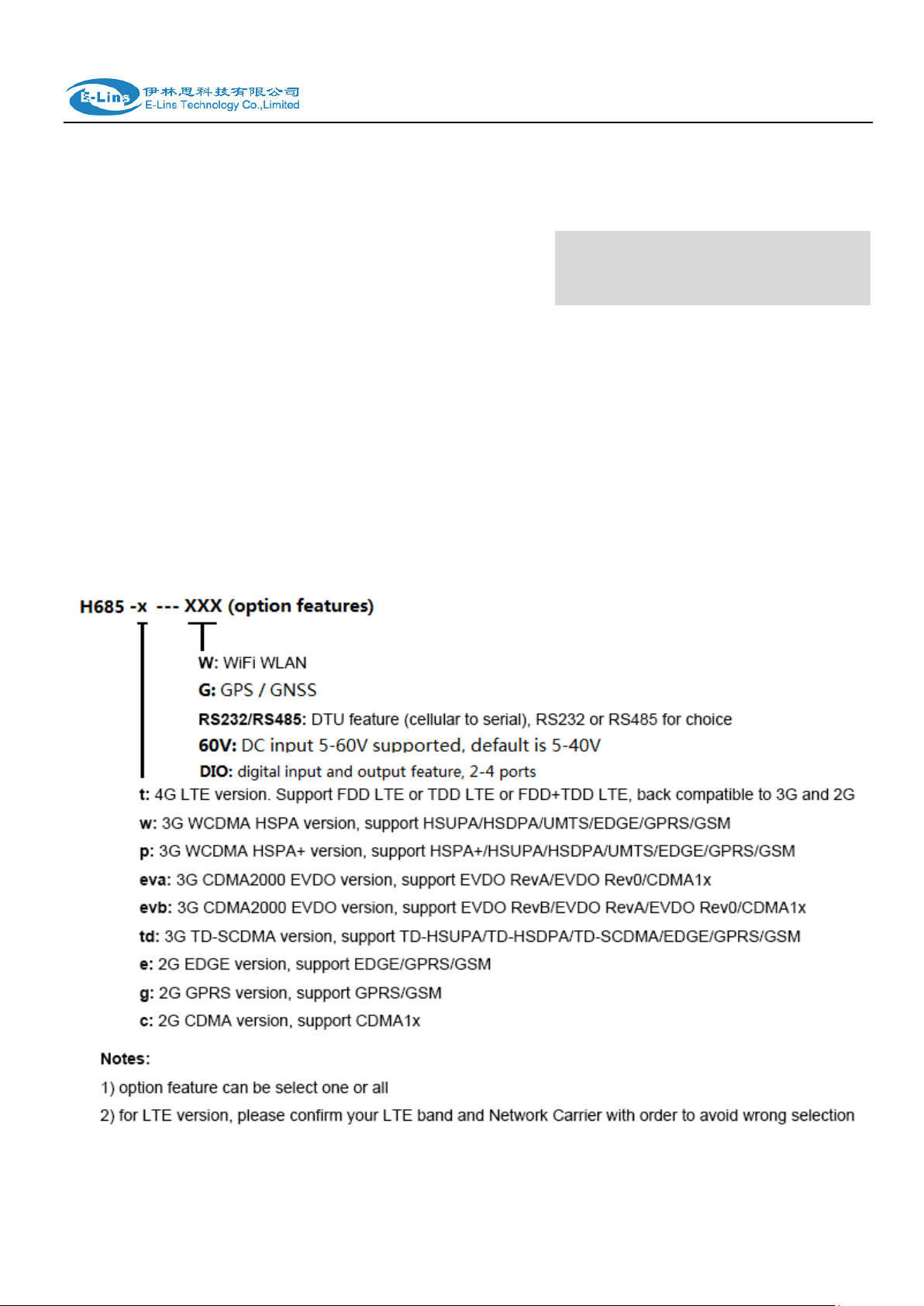
1) H685 series contains different version and option feature. Please learn it before using it.
H685 series defines the model as follows,
E-Lins Technology Co.,Limited
Tel: +86-755-29230581 E-mail: sales@e-lins.com www.e-lins.com

H685 User Manual
Notes: please be informed the following features are option. Please indicate with your
orders.
1) WiFi Feature
2) GPS feature
3) Serial to cellular feature, RS232 or RS485 can choose one
4) Voice/SMS control
5) DC5V~60V
6) BGP, OSPF, RIP, etc.
7) DIO (digital input and output feature)
8) RMS (Remote Management System)
2) Find the modem type info at the back cover of the router. This will be used while do
configuration.
For example: the following label indicates the version, type and inside module modem.
The module modem name is “ME909s-120”, remember this and will select this module name while
do configuration.
E-Lins Technology Co.,Limited
Tel: +86-755-29230581 E-mail: sales@e-lins.com www.e-lins.com

H685 User Manual
1.2 Prepare SIM Card and working condition
1. H685 router has different version. Study your router version before installation.
2. For GSM/GPRS/EDGE/HSDPA/HSUPA/HSPA/HSPA+/4G LTE version, please get a SIM
card with data business.
3. For CDMA2000 EVDO/CDMA1x version, please get a UIM card with data business or
inform us before order if the network uses non-ruim (nam-flashing).
4. Make sure the sim card or uim card is with enough data business and balance.
5. Make sure the signal is good enough where you test or install the router. Weak signal will
make the router no work. If you find your signal strength is not good, please contact us for
high gain antenna.
6. Different countries and carriers use different network band and frequency. E-Lins packs
units with free world-wide-use antenna. It can work, but the data speed or signal may not be
good at your sites. Please buy dedicated high gain antenna from your local suppliers or
contact E-Lins to OEM/ODM the antenna.
1.3 Highly recommendation for the configuration
The wireless cellular is unstable sometimes with some uncertain issue. In order to keep the
router working in the best condition, it is highly recommended that the Cell ICMP Check
feature is activated. Please refer to chapter 3.5.1 to configure.
Chapter 2
2 Hardware Installation
This chapter mainly describes the appearance, model and function of H685 series and how to
install and set the configurations.
1. Overall Dimension
2. Accessories Description
3. Installment
E-Lins Technology Co.,Limited
Tel: +86-755-29230581 E-mail: sales@e-lins.com www.e-lins.com

H685 User Manual
2.1 Overall Dimension
2.2 The Ports
Pictures:
E-Lins Technology Co.,Limited
Tel: +86-755-29230581 E-mail: sales@e-lins.com www.e-lins.com

H685 User Manual
Antenna Connector
Marks
Cell
for main cell antenna
Aux / Cell Aux
for auxiliary cell antenna
WiFi / WLAN / WiFi Aux
for WiFi antenna
GPS
for GPS antenna
LAN: LAN RJ45 Ethernet ports.
WAN: WAN RJ45 Ethernet ports.
RST: sys reset button
PWR: DC power socket. DC5~40V, DC5~50V option depends on the router version.
VCC: DC wire positive pole. DC5~40V, DC5~50V option depends on the router version
GND: DC wire ground
GND: Serial ground
RX: serial receiving
TX: serial transmission
RST: reset router
DIO0: digit I/O port 0
IDO1: digit I/O port 1
NC: not connection (option for DIO ports)
GND: DC wire ground
VCC: DC wire positive pole. DC5~40V, DC5~50V option depends on the router version
WPS: WPS button
Antenna Connection Table
2.3 Installment
H685 series should be installed and configured properly before putting in service. The
installation and configuration should be done or supervise by qualified engineer.
Attention:
E-Lins Technology Co.,Limited
Tel: +86-755-29230581 E-mail: sales@e-lins.com www.e-lins.com

H685 User Manual
Do not install H685 series or connect/disconnect its cable when it is power on.
2.4 SIM/UIM card installed
If your router has SIM/UIM card protector, please remove it, insert the sim card correctly,
and fix the protector.
If your router has no SIM/UIM card protector, please insert the sim card correctly.
Attention: SIM/UIM card does not reach the designated position, the equipment can not
find a card, can't work normally, therefore inserted a try to check again for a SIM
card is stuck fast.
2.5 The installation of terminal blocks
This chapter is for version with terminal blocks only. Default, the H685 is with DB9
connector. Please use DB9 cable to connect H685 and the equipment directly.
The following is for version with terminal blocks only:
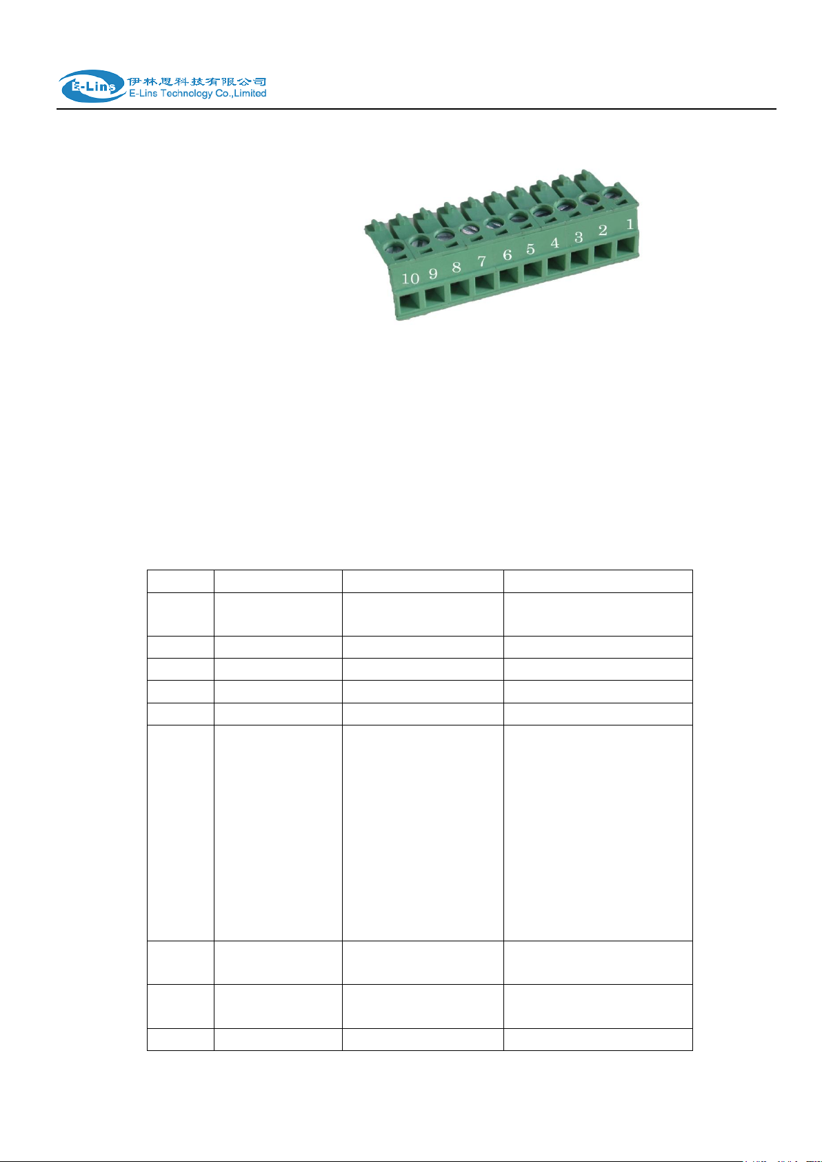
H685 uses pluggable terminals to connect the user‟s data and the power supply. Spacing:
3.81mm,10 Pin; User data and power supply suggestion: 14~24AWG. Please refer to the
table 2-4 for the interface definition of the power cable and connection sequence. Specific
interface definition of the power cable and connection sequence you can read on the
labels of H685 products. Using 14~24AWG cable and referring to H685 products labels
or the bellowed interface definition and connection sequence, you need to use the oblate
screw driver to fix the cable to the connecting jacks of the pluggable terminal. After
successfully connection, you need to insert the terminal into the corresponding position in
the bottom of the H685 products.
Notes: Connection sequence should be accurate
about 7mm. (For safety, insulating striping length should be too long). Please refer
Cable‟s insulating striping length is
。
E-Lins Technology Co.,Limited
Tel: +86-755-29230581 E-mail: sales@e-lins.com www.e-lins.com
H685 User Manual
PIN
Signal
Description
Note
1
VCC
+5-40V DC Input,
+5~50V option
Current: 12V/1A
2
GND
Ground
3 TX
Transmit Data
4 RX
Receive Data
5 PGND
Ground
6
RST
Reset
Reset Pin has the same
function with reset
button. In the usage, it
needs to be short
connected to the GND.
After giving the device a
1 sec low level, it will
reboot.3 seconds, the
device will restore
factory settings
7
DIO0
General Purpose
I/O
8
DIO1
General Purpose
I/O 9
NC
Not connect
Reserved for DIO2
to the picture.
Attention:
1. The power cable should be connected correctly. We “suggestion double check before
switch it on .Wrong connections may destroy the equipment.
2. Power terminals: Pin 1 and Pin 2;
3. Here:Pin 2 is “GND”, PIN 1 is power input “Vin”(DC5~40V, or DV5~50V).
E-Lins Technology Co.,Limited
Tel: +86-755-29230581 E-mail: sales@e-lins.com www.e-lins.com
I/O Terminal on router
Serial port (RS485 or RS232)
Port 3 (GND)
Pin 5
Port 4 (RX)
Pin 2
Port 5 (TX)
Pin 3
Attention:
The H685 supports POE (Power over Ethernet). It supports 5-40VDC default, it the POE
voltage is 48V, please order 5-60VDC version, otherwise it will defeat the hardware of H685.
10
NC
Not connect
Reserved for DIO3
Notes: If not through, can switch Port4 and port5.
2.6 Grounding
To ensure a safe, stable and reliable H685 series operation, Router cabinet should be
grounded properly.
H685 User Manual
2.7 Power Supply
H685 series can be applied to complicated external environment and usually the power
range is very large. So in order to fit the complicated application environment and improve
the stability of the system, H685 series is designed with advanced power management
technology. The DC power supply electronic to the device via the pluggable terminal PIN
2(GND) and PIN 1(Vin). Please refer to the above table for the detail definition of the
terminal.
Normally, H685 series input powers supply is +5~+40V (if your H685 support 50V, the
option is +5~+50V). In most cases, the standard configuration is 12V/1A.
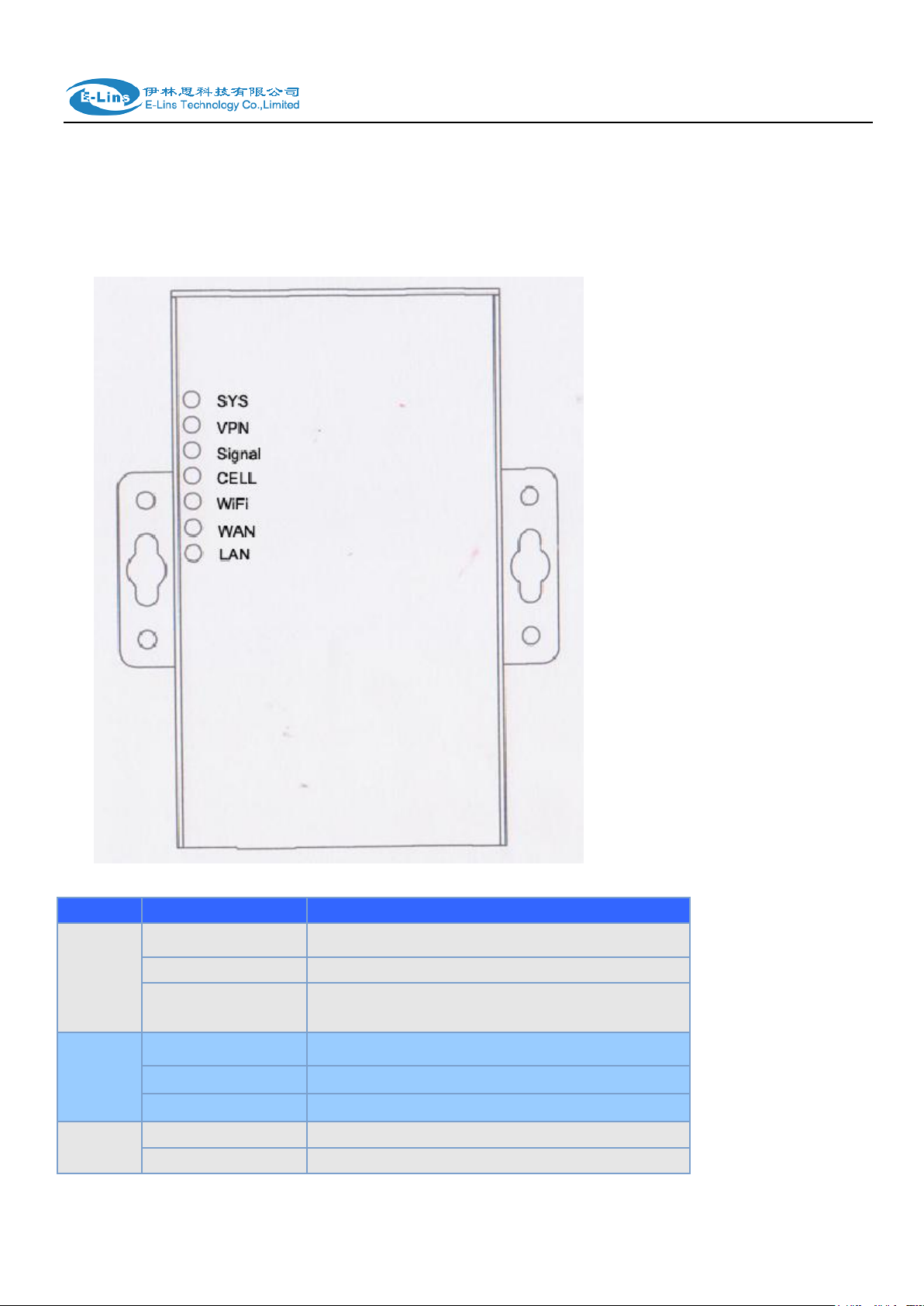
2.8 LED and Check Network Status
Please connect the antenna after you successfully connect to the cable. And then insert the
E-Lins Technology Co.,Limited
Tel: +86-755-29230581 E-mail: sales@e-lins.com www.e-lins.com
H685 User Manual
LED
Indication Light
Description
SYS
On for 25 seconds
On for 25 seconds after power supply
blink
System set-up normally
Off or still on after 25
seconds
System set-up failure
LAN
blink
Data transmission in Ethernet
Off
Ethernet connection abnormal
On
Ethernet is connected
VPN
On
IPSec VPN tunnel set-up
Off
IPsec VPN tunnel set-up failure or inactivated
valid SIM/UIM card and provide the power to the H685 series via the cable. After provide the
power to H685, if the SYS LED starts to blink in a few seconds, that means the system start-up
is normal; if the CELL LED works, that means the network is online; if the VPN light works, that
means VPN tunnel has been set up. Please refer to the below table for the situation of the
indication lights.
Tel: +86-755-29230581 E-mail: sales@e-lins.com www.e-lins.com
E-Lins Technology Co.,Limited

H685 User Manual
CELL
On
Access to the Internet/Private Network
WiFi
On
Enable
Off
Disable
WAN
blink
Data transmission in Ethernet
Off
Ethernet connection abnormal
On
Ethernet is connected
Signal
Off
No signal, or signal checking is not ready
blink ( 2 seconds for
on, and 2 seconds
for off)
Signal bar is 1
blink ( 1 seconds for
on, and 1 seconds
for off)
Signal bar is 2
blink ( 0.5 seconds
for on, and 0.5
seconds for off)
Signal bar is 3
Chapter 3
3 Software configuration
1. Overview
2. How to log into the Router
3. How to config web
3.1 Overview
H685 series routers with built-in WEB interface configuration, management and debugging
tools, user should configuration the parameters first; and it could be altered the parameters
flexibility and software upgrades and simple testing. User can set up and manage the
parameters of the router on its interface, detail step are bellow:
Tel: +86-755-29230581 E-mail: sales@e-lins.com www.e-lins.com
E-Lins Technology Co.,Limited
H685 User Manual
3.2 How to log into the Router
3.2.1 Network Configuration of the Computer.
The router default parameters as follow
Default IP: 192.168.1.1, sub mask: 255.255.255.0.
There are two ways to set the PC‟s IP address.
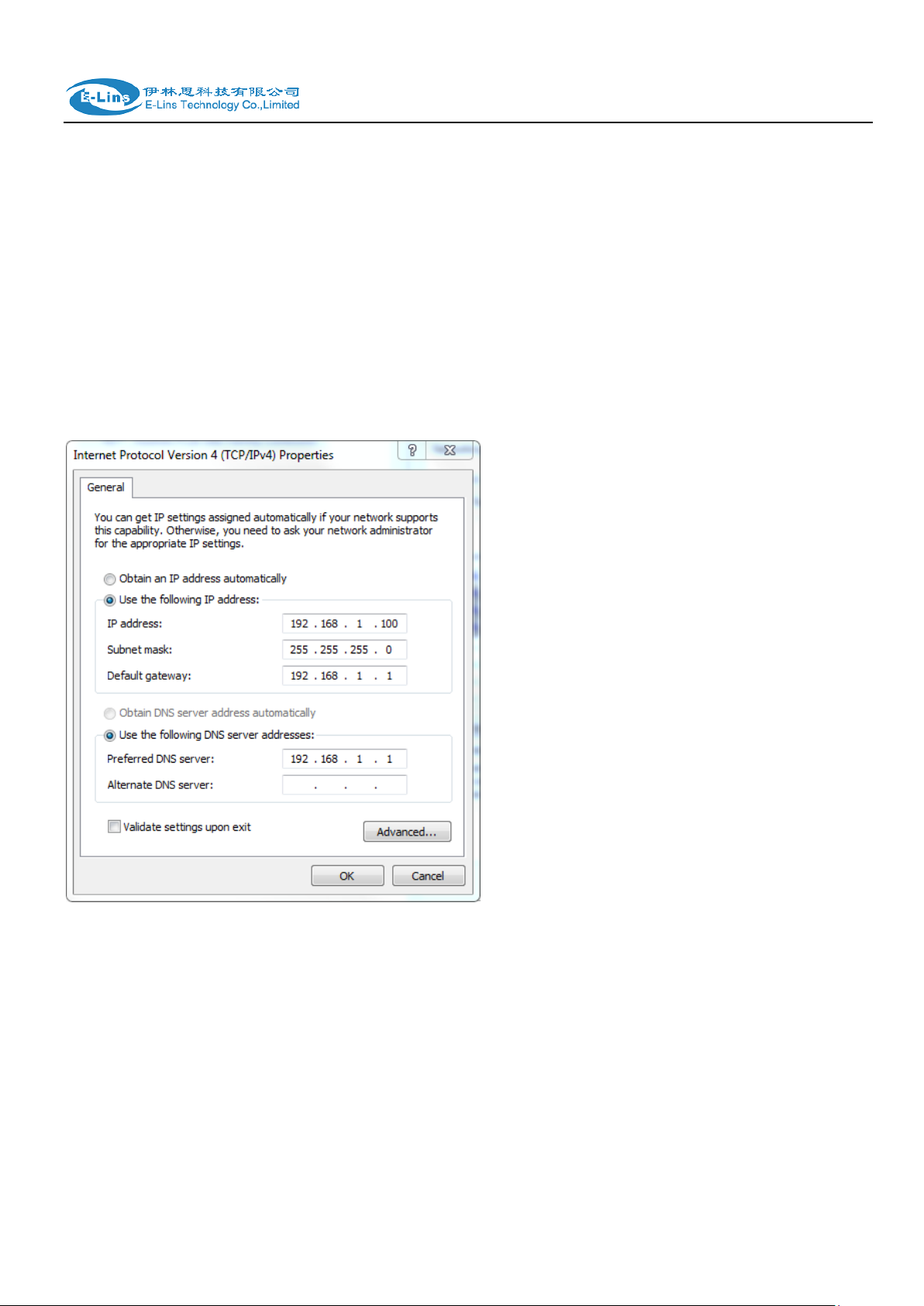
Way 1) Manual setting
Set the PC IP as 192.168.1.xxx (xxx = 2~254), subnet mask: 255.255.255.0, default
gateway: 192.168.1.1, primary DNS: 192.168.1.1.
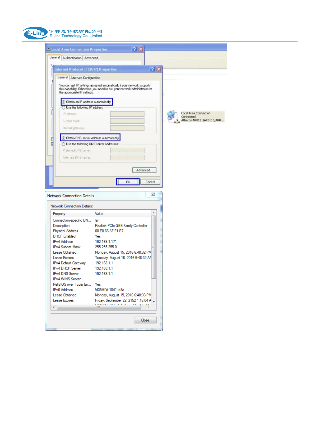
Way 2) DHCP
Choose “Obtain an IP address automatically” and “Obtain DNS server address
automatically”.
E-Lins Technology Co.,Limited
Tel: +86-755-29230581 E-mail: sales@e-lins.com www.e-lins.com
H685 User Manual
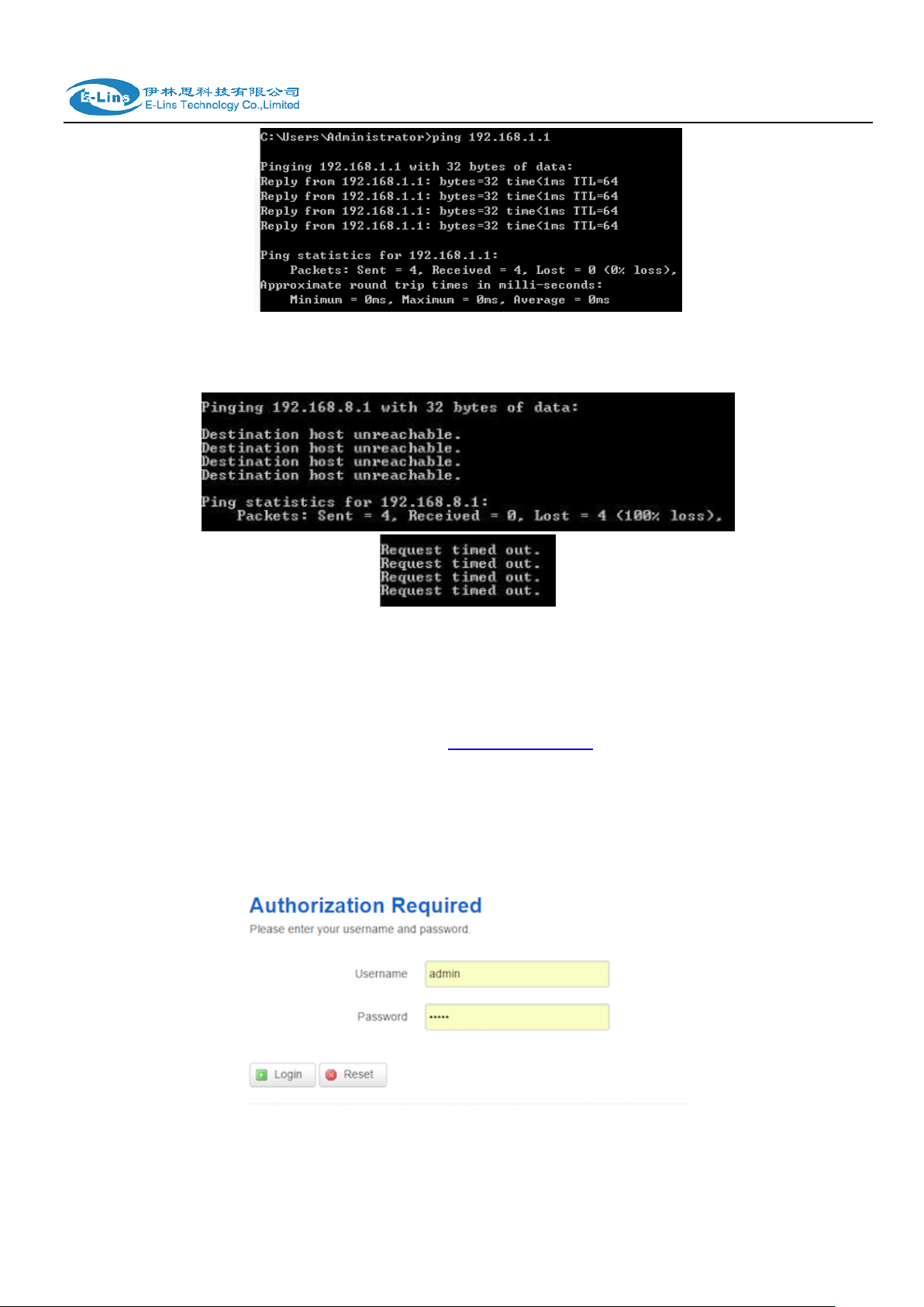
After IP setting, check it by ping. Click Windows start menu, run, execute “cmd” command.
Input “ping 192.168.1.1” in the DOS window.
E-Lins Technology Co.,Limited
Tel: +86-755-29230581 E-mail: sales@e-lins.com www.e-lins.com
H685 User Manual
This information means the connection is work.
This information means the connection is failure. If so, please check the network cable
connection and IP address setting, and can refer to Chapter 4.9.
3.2.2 Log into Router
Open the Web Browser, and type http://192.168.1.1 into the address field and press
Enter bottom in your computer keyboard.
Type User Name “admin” and Password “admin” in the Login page, and then press the
“Login” button.
If you type into the correct User Name and Password, you will get the access into the
Router‟s status overview page.
E-Lins Technology Co.,Limited
Tel: +86-755-29230581 E-mail: sales@e-lins.com www.e-lins.com
H685 User Manual
3.3 Router status
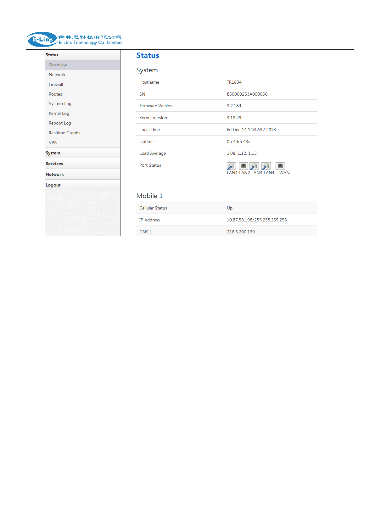
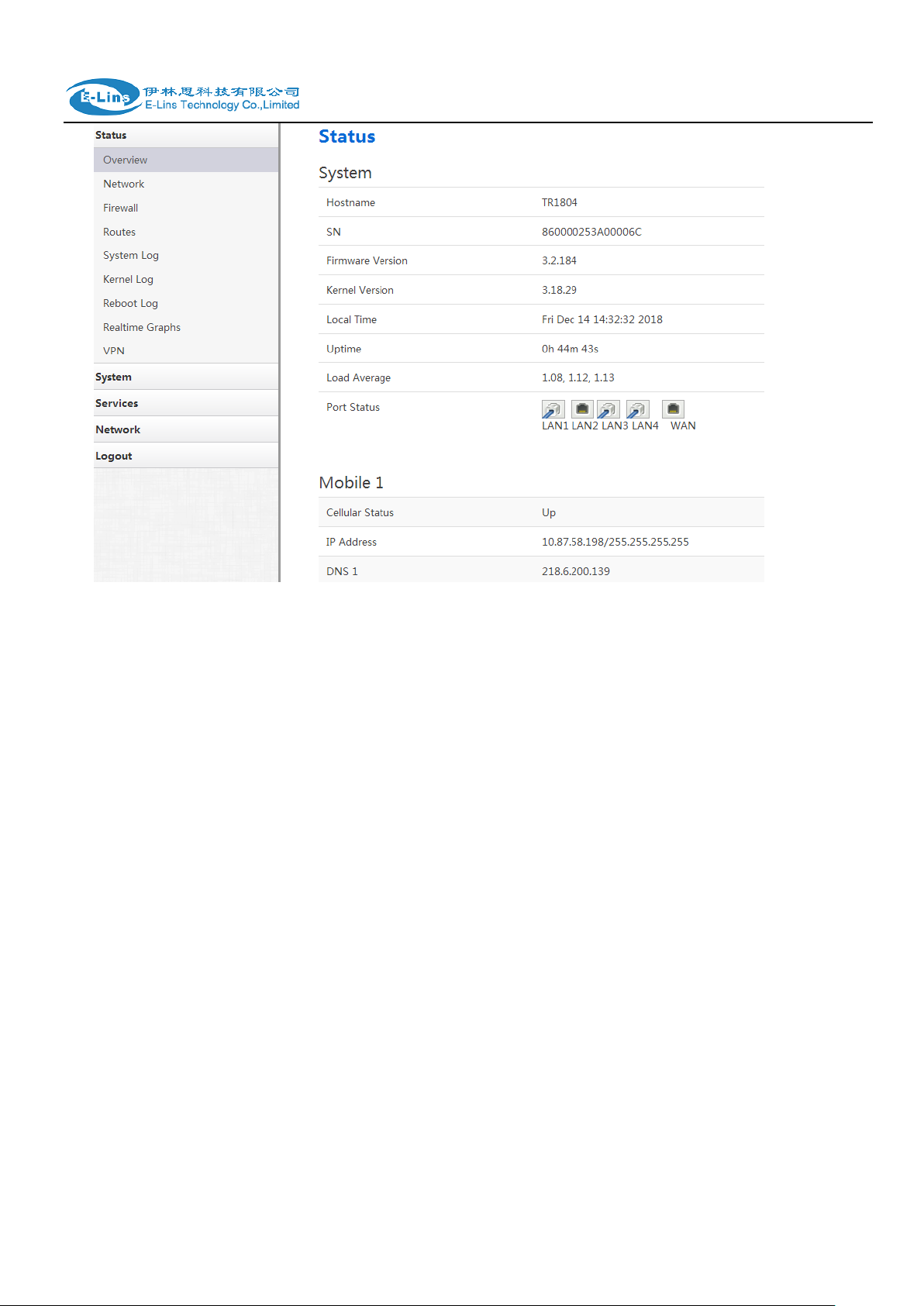
3.3.1 Status overview
Click “Status” in the navigation bar, and then click “Overview”.
E-Lins Technology Co.,Limited
Tel: +86-755-29230581 E-mail: sales@e-lins.com www.e-lins.com
H685 User Manual
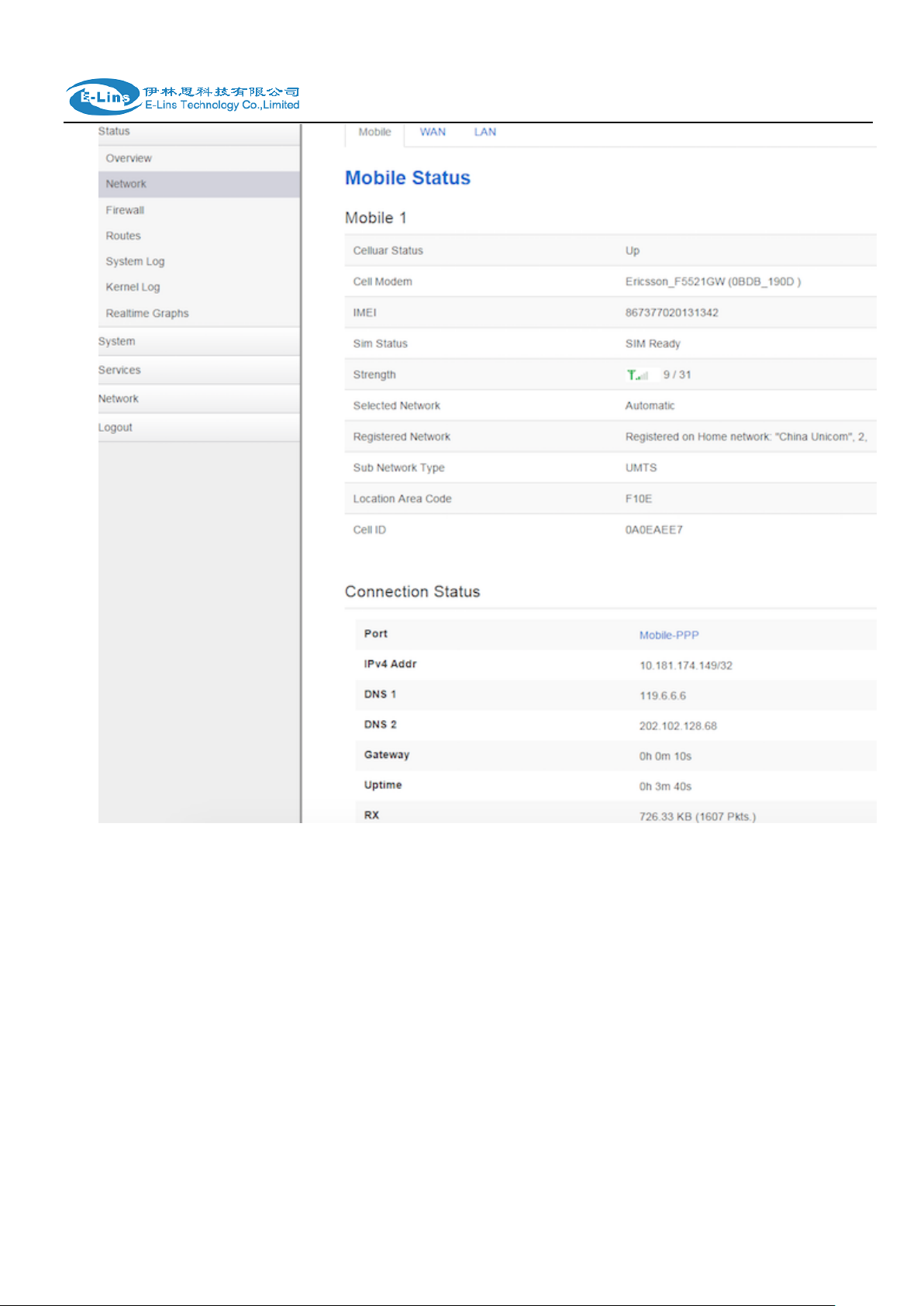
3.3.2 Network status
Network status pages show detail information of cell mobile interface, WAN and LAN.
Cell mobile interface page:
E-Lins Technology Co.,Limited
Tel: +86-755-29230581 E-mail: sales@e-lins.com www.e-lins.com
H685 User Manual
WAN status page:
Tel: +86-755-29230581 E-mail: sales@e-lins.com www.e-lins.com
E-Lins Technology Co.,Limited
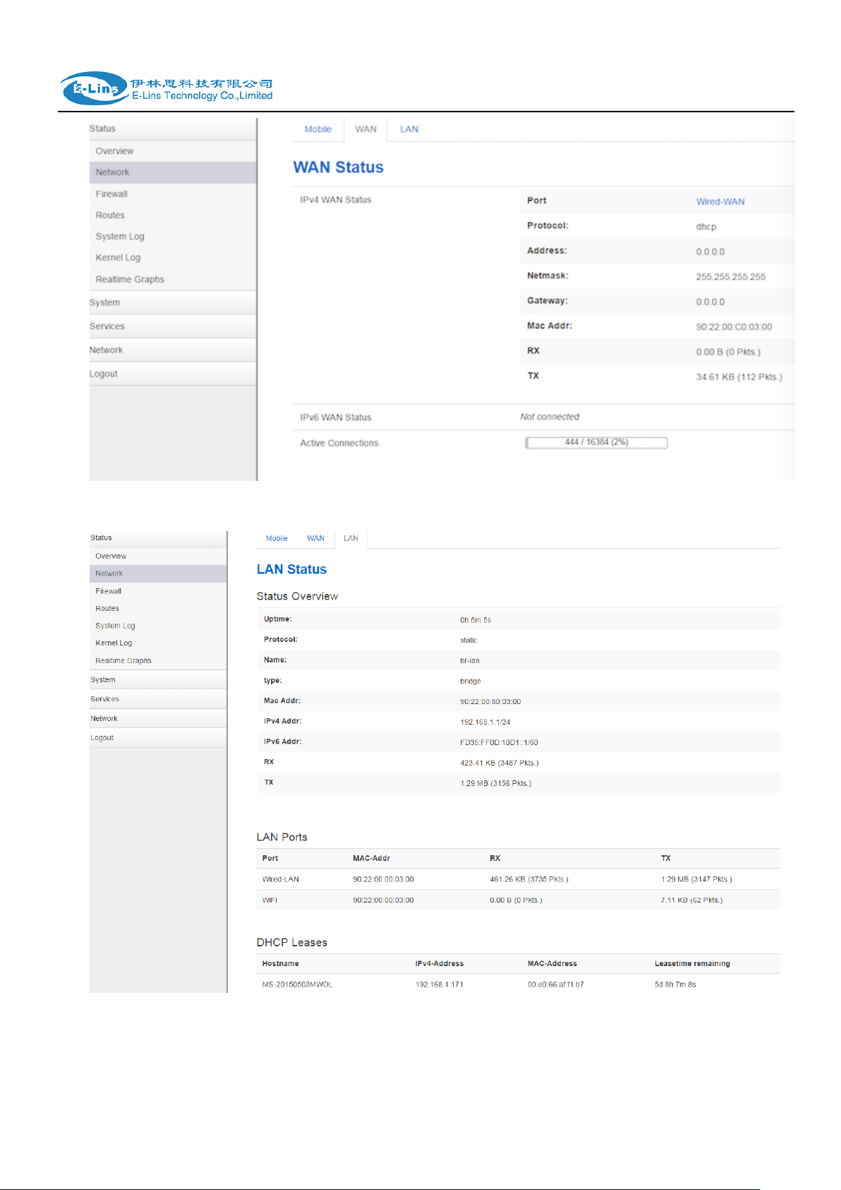
LAN status page:
H685 User Manual
E-Lins Technology Co.,Limited
Tel: +86-755-29230581 E-mail: sales@e-lins.com www.e-lins.com

H685 User Manual
3.3.3 Firewall status
Firewall status page shows IPv4 and IPv6 rules and counters. The final user can reset
counters and restart firewall functionality here.
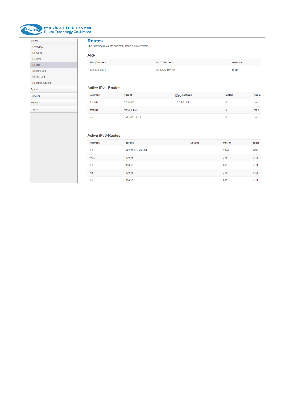
3.3.4 Routes
Routes page shows rules which are currently active on this router. And ARP table is displayed
as well.
E-Lins Technology Co.,Limited
Tel: +86-755-29230581 E-mail: sales@e-lins.com www.e-lins.com
H685 User Manual
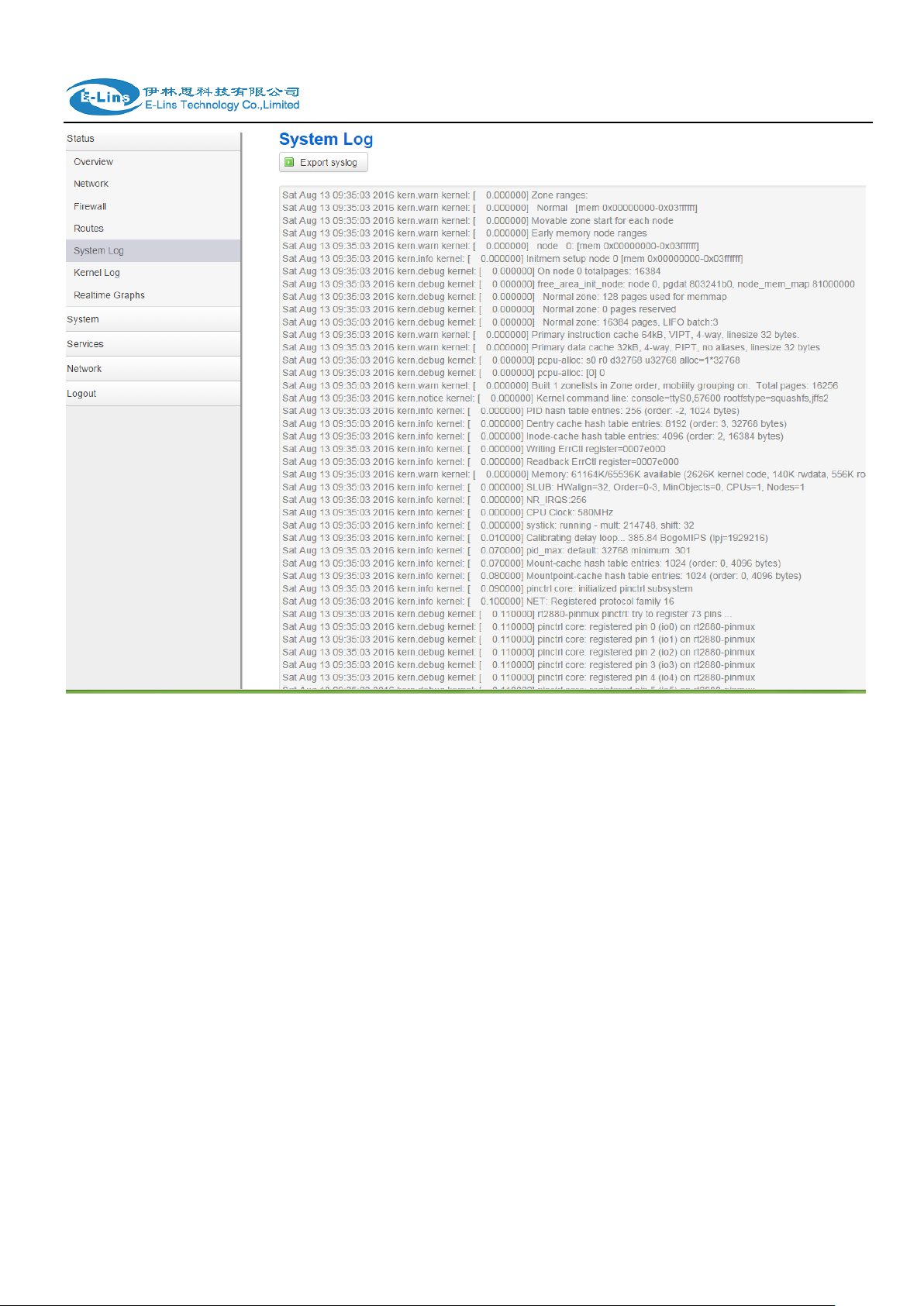
3.3.5 System log
This page shows system log from system boot up. System log is not saved when router
restarts. It can be exported by click button “Export syslog”.
E-Lins Technology Co.,Limited
Tel: +86-755-29230581 E-mail: sales@e-lins.com www.e-lins.com
H685 User Manual
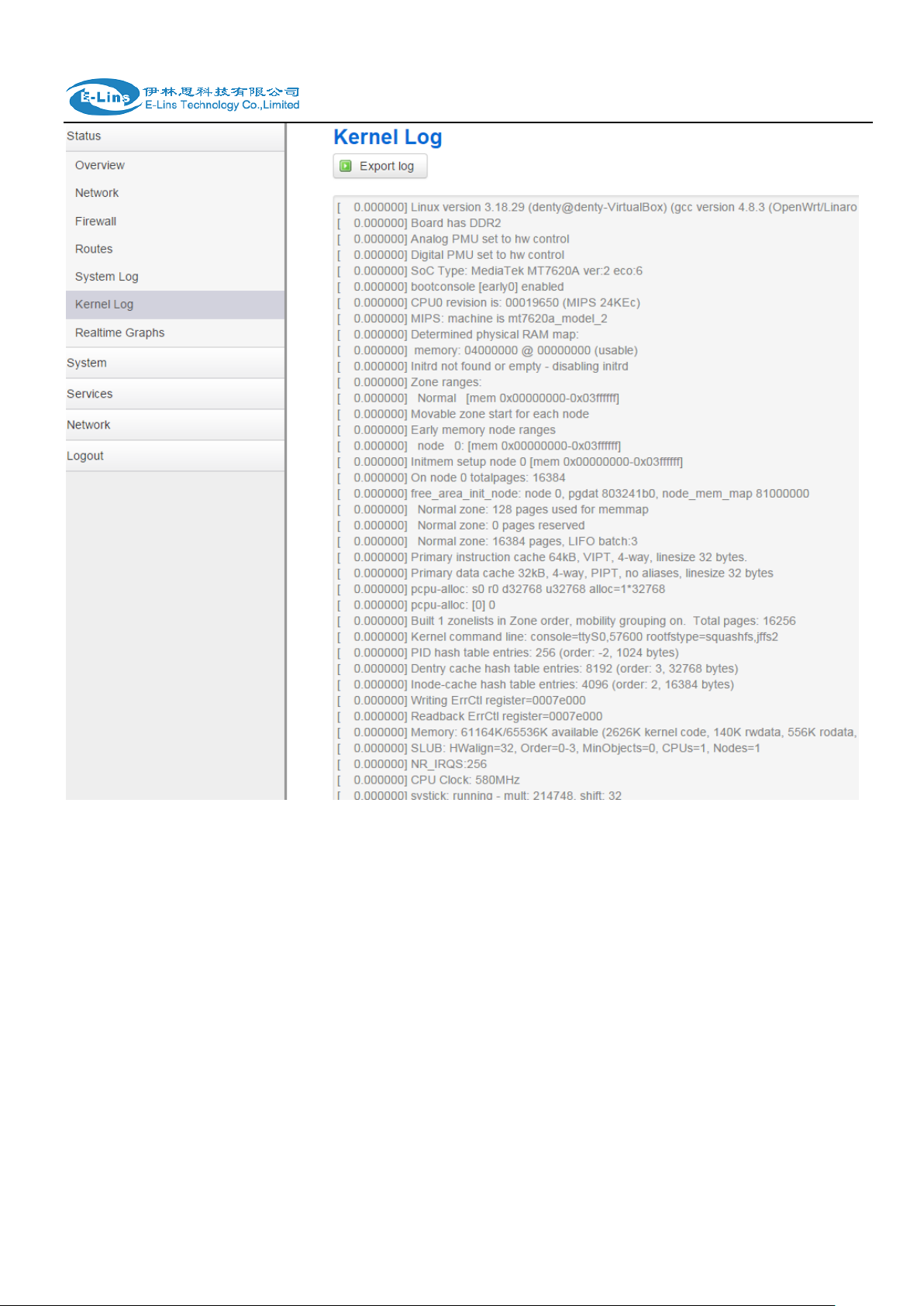
3.3.6 Kernel log
This page shows Kernel log from system boot up. This log is not saved when router restarts. It
can be exported by click button “Export syslog”.
E-Lins Technology Co.,Limited
Tel: +86-755-29230581 E-mail: sales@e-lins.com www.e-lins.com
H685 User Manual
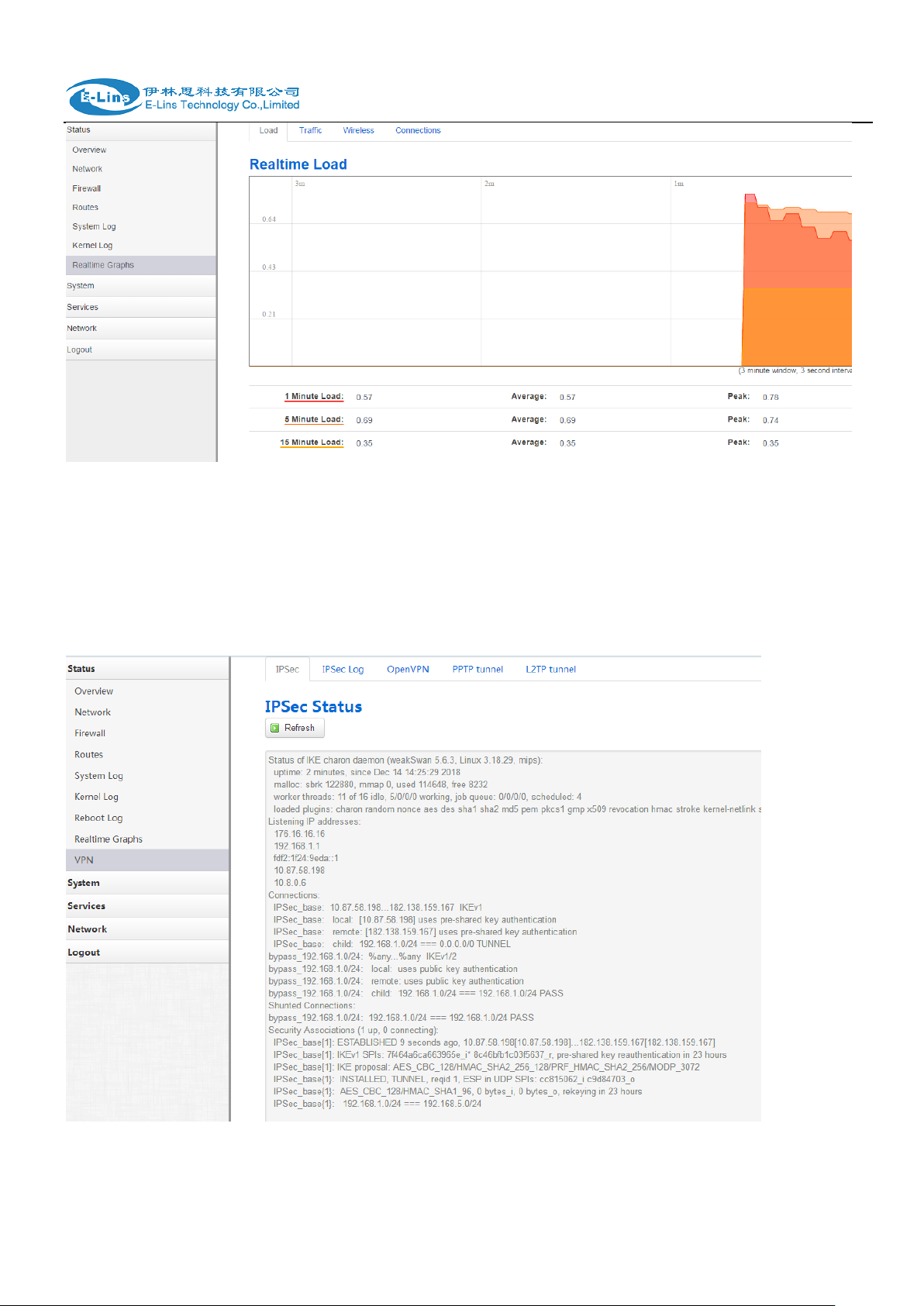
3.3.7 Realtime graphs
Realtime Graphs page shows real time system load,interfaces traffic, etc..
E-Lins Technology Co.,Limited
Tel: +86-755-29230581 E-mail: sales@e-lins.com www.e-lins.com
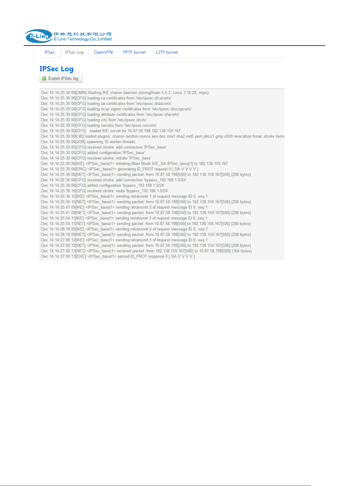
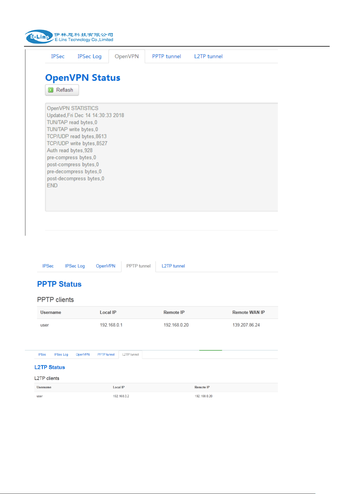
3.3.8 VPN
H685 User Manual
show IPSec status, IPSec log, OpenVPN status, PPTP status and L2TP status.
IPSec Status page
IPSec Log page
E-Lins Technology Co.,Limited
Tel: +86-755-29230581 E-mail: sales@e-lins.com www.e-lins.com
H685 User Manual
OpenVPN status page
E-Lins Technology Co.,Limited
Tel: +86-755-29230581 E-mail: sales@e-lins.com www.e-lins.com
H685 User Manual
PPTP Client Status page
L2TP Client Status page
E-Lins Technology Co.,Limited
Tel: +86-755-29230581 E-mail: sales@e-lins.com www.e-lins.com
H685 User Manual
3.4 System Configuration
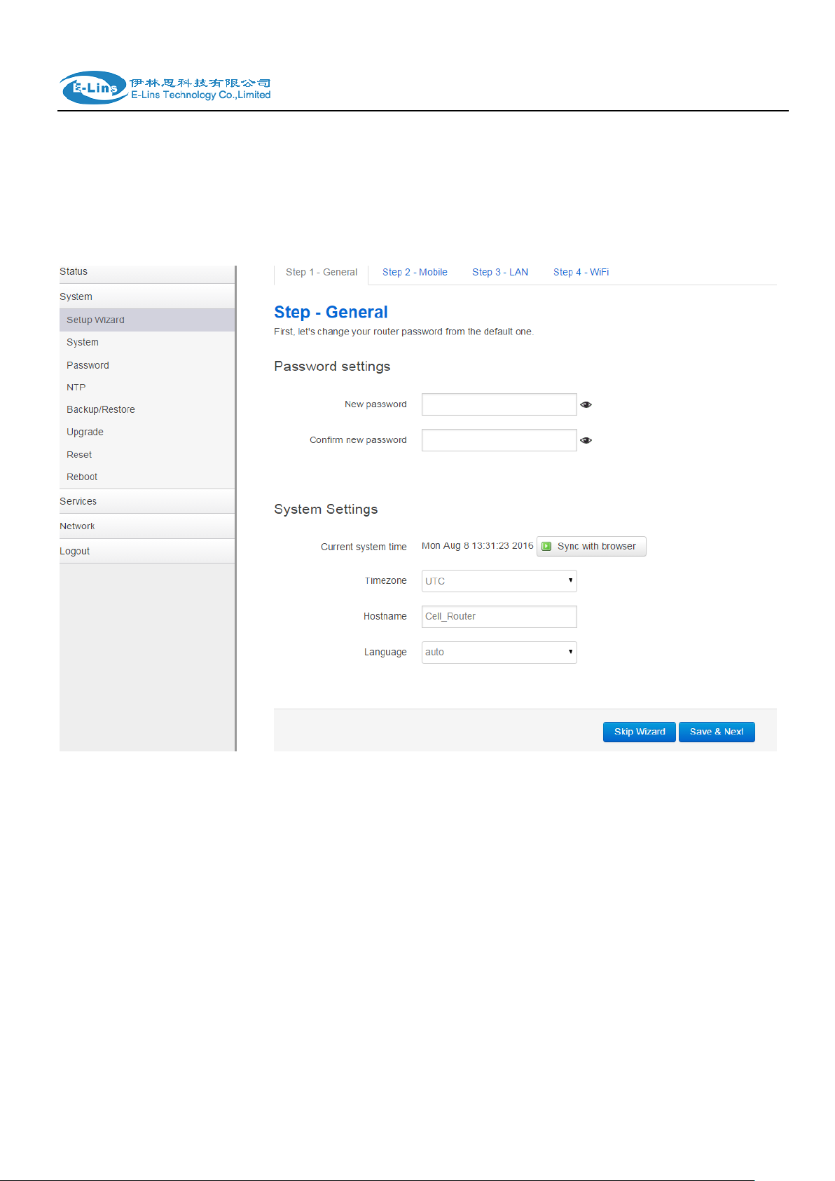
3.4.1 Setup wizard
When login in router at the first time, setup wizard pages show.
Note: pressing button “Save & Next” will save configuration and jump to the next page. All
configurations will be applied after click button “Finish” at the final step (Step-WiFi).
E-Lins Technology Co.,Limited
Tel: +86-755-29230581 E-mail: sales@e-lins.com www.e-lins.com
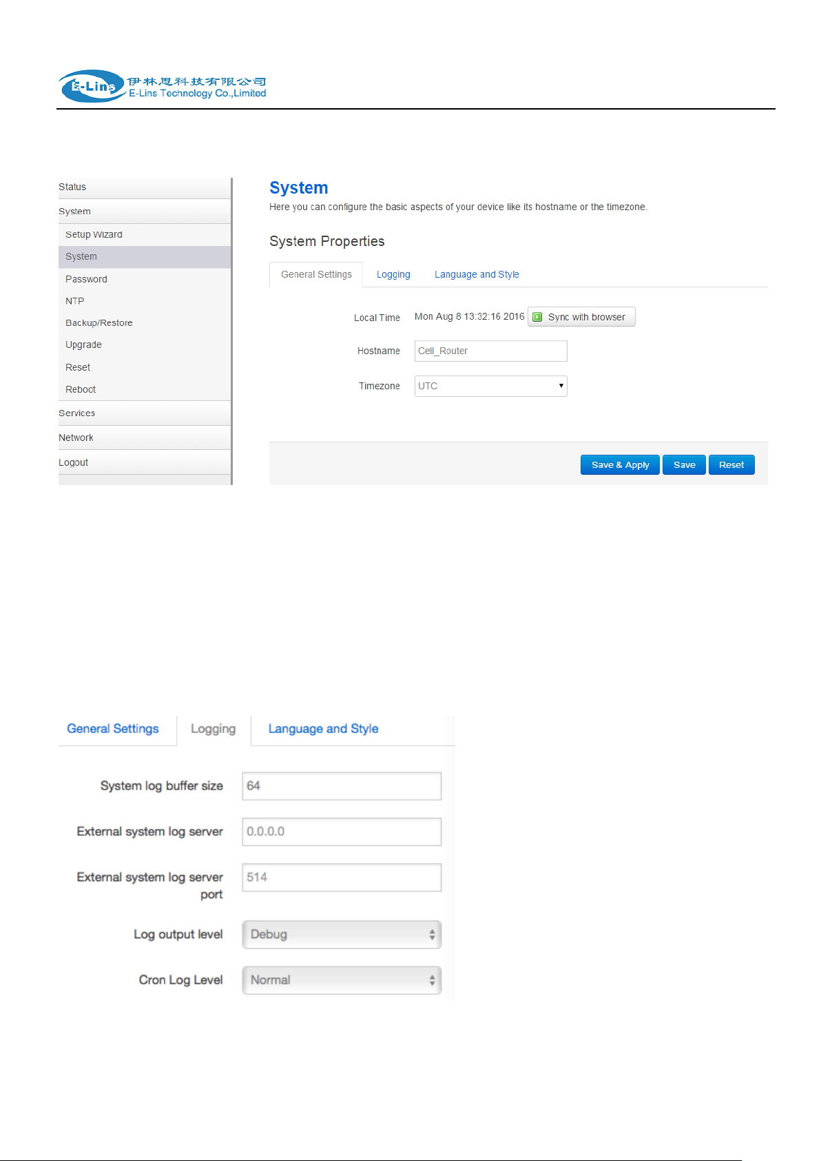
3.4.2 System
H685 User Manual
General Settings
Local Time
It displays system time, and the final user can Sync this time with browser by clicking button
“Sync with browser”.
Hostname
It is the router‟s name, the default name is Cell_Router.
Time zone
Select a suitable time zone. The default value is UTC
Logging settings
System log buffer size
Tel: +86-755-29230581 E-mail: sales@e-lins.com www.e-lins.com
E-Lins Technology Co.,Limited
H685 User Manual
The unit is KB, default value is 64 KB. If the real log size is bigger than the value configured,
the oldest log will be dropped.
External system log server
The IP address of external log server. The final user can setup a Linux machine with syslogd
run as log server.
External system log server port
The UDP port of external log server.
Log output level
Log level, the default is debug with highest level, Emergency is the lowest level.
Cron log level
It is log level for process Crond.
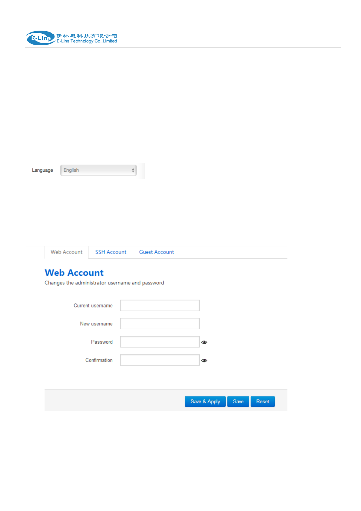
Language
The default language is “Auto”. The final user can choose English or Chinese.
3.4.3 Password
Change username and password for accessing device web. Click “eye button” can show the new
password you entered.
Current username. The username of web account is using.
E-Lins Technology Co.,Limited
Tel: +86-755-29230581 E-mail: sales@e-lins.com www.e-lins.com

H685 User Manual
New username: change web account username to the new one.
Password: new password.
Confirmation: same as Password.
Change the username and password for ssh access.
E-Lins Technology Co.,Limited
Tel: +86-755-29230581 E-mail: sales@e-lins.com www.e-lins.com

H685 User Manual
Change the password for guest user.
3.4.4 NTP
NTP is network timing protocol.
Enable NTP client
The default value is enabled. Router acts as a NTP client.
Provide NTP server
The default value is unchecked. Router acts as a NTP server.
NTP sync count
NTP running counts after router connects to internet,0 or empty means infinite.
NTP sync interval(min)
The interval time between NTP synchronization.
NTP server candidates
E-Lins Technology Co.,Limited
Tel: +86-755-29230581 E-mail: sales@e-lins.com www.e-lins.com

H685 User Manual
It is NTP server list, multiple NTP server is acceped. The final user can click the button to
delete an entry, or click button to add a new entry.
3.4.5 Backup/Restore
It is used for configuration files backup and restore.
For backup configuration files, click button “Download”, an archive file will be generated and be
downloaded to your PC automatically.
For restore configuration files, you can click button “Choose File”, then select an archived
configuration file, and finally click button “Upload”, then system will load this file and apply it, and
then restart router.
3.4.6 Upgrade
E-Lins Technology Co.,Limited
Tel: +86-755-29230581 E-mail: sales@e-lins.com www.e-lins.com

H685 User Manual
Upload a system compatible firmware to replace the running firmware. The default value for “Keep
settings” is checked, that means current configuration will be kept after system upgrade, otherwise
router will be reset to factory setting. But we highly recommend uncheck “Keep settings”,
otherwise it may bring uncertain parameters conflicting after updating.
Safe upgrade option is checked by default. Please always keep it checked to avoid broken
firmware.
Click button “Choose File” to select a compatible firmware then click button “Upload image…”.
Router will do a basic checking for the uploaded file. If it is not compatible file, an error will be
generated like this:
If the firmware file is OK, it will go to the verify page, then click button “Proceed”, and system will
restart soon.
E-Lins Technology Co.,Limited
Tel: +86-755-29230581 E-mail: sales@e-lins.com www.e-lins.com

H685 User Manual
3.4.7 Reset
Reset all configurations to factory default, after click buttong “Reset”, there is pop dialog to ask it‟s
really to reset, click button “cancel” will do nothing, click button “OK” will reset all configuration to
default and restart system.
3.4.8 Reboot
Reboot at time: reboot router at a specific time.
E-Lins Technology Co.,Limited
Tel: +86-755-29230581 E-mail: sales@e-lins.com www.e-lins.com

H685 User Manual
Reboot when timeout: reboot router after timer timeout.
Click button “Reboot Now”, the system will restart in several seconds.
3.5 Services configuration
3.5.1 ICMP check
For router working with best stability, we highly suggest activate and use this feature.
With this feature, the Router will automatically detect its working status and fix the problem.
Enable: Enable ICMP check feature
Host1 to ping / Host2 to ping: The domain name or IP address for checking the network
connection.
Ping timeout: If ping packet is sent, the response packet is not received before timeout, then
this ping is failed.
Max retries: If the ping is failed, the failed counter will add one. If the failed counter is bigger or
E-Lins Technology Co.,Limited
Tel: +86-755-29230581 E-mail: sales@e-lins.com www.e-lins.com

H685 User Manual
equal to the Max retries, then system will say the ICMP check is failed, an action configured in
item “Action when failed” will be triggered.
If the ping is succeeding, failed counter will be reset to 0 at anytime.
Interval between ping: The time between twice ping. The unit is minute.
Reconnect: Reconnect cell interface if ping failed.
Action when failed: there are “Restart module” and “Restart router”. “Restart module” will fix
the problem from radio module, and “Restart router” will fix the problem from the whole system
including radio module.
3.5.2 VRRP
Enable: Enable VRRP(Virtual Router Redundancy Protocol) for LAN.
E-Lins Technology Co.,Limited
Tel: +86-755-29230581 E-mail: sales@e-lins.com www.e-lins.com

H685 User Manual
Virtual ID: Routers with same IDs will be grouped in the same VRRP (Virtual Router
Redundancy Protocol) cluster, range [1 - 255].
Virtual IP address: Virtual IP address(es) for LAN‟s VRRP cluster. IP address entry can be
deleted by click button , or added by click button .
Priority: Router with highest priority in the same VRRP cluster will act as master. The legal
number is from 1 to 255.
Advertisement interval: VRRP send packet to a set of VRRP instances to advertise the device
in the MASTER state.
Password: the password string for VRRP accessing. VRRP in our device only supports
authentication PASS.
Track interface: Check local interface is up or down.
Track IP/Host: the host or IP address to ping.
Track Interval: ping interval.
Track Weight: priority will be subtracted from the initial priority in case of ping IP/Host failure.
Status: show VRRP status(MASTER/BACKUP).
E-Lins Technology Co.,Limited
Tel: +86-755-29230581 E-mail: sales@e-lins.com www.e-lins.com

H685 User Manual
3.5.3 Failover (link backup)
3.5.3.1 Failover basic settings
Enable: Enable failover feature
Back to high priority: If back to high priority is checked, when the high priority interface is
available, using the high priority interface as WAN port.
If back to high priotrity is unchecked, even if the high priority interface is available, router will
keep current interface as WAN port, it won‟t switch to high priority interface.
Primary/Secondary/Third: interface which can be treat as WAN port. There are 4 options,
Wired-WAN, Wifi_client, Cell_mobile, and None.
Current interface: show working interface,
Host 1 to ping / Host 2 to ping: It is external IP address or domain name for checking the
connection is available.
E-Lins Technology Co.,Limited
Tel: +86-755-29230581 E-mail: sales@e-lins.com www.e-lins.com

H685 User Manual
Notes:
1) This feature is for H685 with DTU option only.
2) This feature is conflict with “Connect Radio module” and “GPS send to serial”. Please
disable the “DTU” feature if use “Connect Radio Module” or “GPS send to serial” feature.
Ping timeout: If ping packet is sent, the response packet is not received before timeout, then
this ping is failed.
Max retries: If the ping is failed, the failed counter will add one. If the failed counter is bigger or
equal to the Max retries, then system will say this interface is unavailable.
If the ping is succeeding, failed counter will be reset to 0 at anytime.
Interval between ping: The time between twice ping. The unit is second.
3.5.3.1 Failover Advanced settings
Cell Standby: choose Cell status(connect, disconnect, or radio off) when cell acts as backup
interface.
SMS Alarm: if need to send SMS alarm when working interface switchover.
3.5.4 DTU
E-Lins Technology Co.,Limited
Tel: +86-755-29230581 E-mail: sales@e-lins.com www.e-lins.com

H685 User Manual
Enable: Enable DTU feature.
Send DTU ID: Send DTU ID at the front of packet.
DTU ID: The default DTU ID is the SN of router, the final user can re-write it if necessary.
Send DTU ID on initial connection: only .
Forward delay: The unit is millisecond. It is delay time that forward data between serial port
and network. Set forward delay to empty means no delay.
Terminate character: split serial port data into different packages with terminate character. It
can be a string, or hexadecimal which start as 0x,such as 0x0a0d.
Debug: Debug level for log output.
serial baudrate: support 300/1200/2400/4800/9600/19200/38400/57600/115200bps
serial parity: support none/odd/even
serial databits: support 7 bits and 8 bits
serial stopbit: support 1 bits and 2 bits
E-Lins Technology Co.,Limited
Tel: +86-755-29230581 E-mail: sales@e-lins.com www.e-lins.com

H685 User Manual
Notes:
The maximum number of DTU center is 32.
Protocol: TCP and UDP are supported
Service mode: Client and Server are supported.
Enable heartbeat: The heartbeat is used for connection keep alive.
Heartbeat interval: The time between two heartbeat packet.
Heartbeat content: The content of heartbeat packet.
DTU center Configuration: DTU center is the DTU server, the final user can input the center
name and click button “Add” to add a new center here.
If the center is not needed, the final user can click button “Delete” to delete it, or set it to
disabled.
Tel: +86-755-29230581 E-mail: sales@e-lins.com www.e-lins.com
E-Lins Technology Co.,Limited

H685 User Manual
When select Service mode as Server. There are 2 options.
Server port: the port for client to connect.
Max connections: the max amount of clients can connect.
3.5.5 SNMP
Enable SNMP: Enable SNMP feature
Remote Access: Allow remote access SNMP. If it is unchecked, only LAN subnet can access
SNMP.
Contact: Set the contact information here
Location: set router‟s installation address.
Name: Set the router‟s in SNMP
Port: SNMP service port, the default value is 161.
E-Lins Technology Co.,Limited
Tel: +86-755-29230581 E-mail: sales@e-lins.com www.e-lins.com

H685 User Manual
Get Community: The username for SNMP get. The default value is public. SNMP get is
read-only.
Get Host/Lan: The network range to get the router via SNMP, default we set all as 0.0.0.0./0
Set Community: The username for SNMP set. The default value is private. SNMP set is
read-write.
Set Host/Lan: The network range to set the router via SNMP, default we set all as 0.0.0.0./0
User: SNMPv3 username
Security Mode: three options: None, private and Authorized. If it is set to None, there is no
password required. If it is set to Authorized, only Authentication method and password required.
Authentication: Authentication method, two options: MD5 and SHA.
Encryption: Encryption method, DES and AES supported.
Authentication password: SNMPv3 authentication password, at least 8 characters is required.
Encryption password: SNMPv3 encryption password, at least 8 characters is required.
After all items is setup, click button “Save & Apply” to enable SNMP functionality.
E-Lins Technology Co.,Limited
Tel: +86-755-29230581 E-mail: sales@e-lins.com www.e-lins.com

3.5.6 GPS
H685 User Manual
Enable: please check it once you need use GPS feature.
Only GPRMC: if check it, only send GPRMC data info (Longitude Latitude altitude)
Prefix SN No.: if check it, add the router SN to the data packet
Send interval: configure the frequency time of updated GPS data packet sending
GPS Send to: Choose “Serial” or “TCP/IP” method. The router only receives the GPS signal,
will not process it. It will just send the received GPS signal to your GPS processor devices or
servers.
If the GPS processor device is connected to the H685 Router via Serial Port, please choose
“Serial”.
If the GPS processor device is a remote server, please choose “Serial”.
GPS to TCP/UDP Settings
Server IP: fill in the correct destination server IP or domain name
Server port: fill in the correct destination server port
E-Lins Technology Co.,Limited
Tel: +86-755-29230581 E-mail: sales@e-lins.com www.e-lins.com

H685 User Manual
serial baudrate: 9600/19200/38400/57600/115200bps for choice
serial parity: none/odd/even for choice
serial databits: 7/8 for choice
serial stopbits: 1/2 for choice
serial flow control: none/hardware/software for choice
3.5.7 SMS
SMS Command
E-Lins Technology Co.,Limited
Tel: +86-755-29230581 E-mail: sales@e-lins.com www.e-lins.com

H685 User Manual
Enable: check it to enable SMS command feature.
E-Lins Technology Co.,Limited
Tel: +86-755-29230581 E-mail: sales@e-lins.com www.e-lins.com

H685 User Manual
SMS ACK: If checked, the router will send command feedback to sender‟s phone number. If
unchecked, the router will not send command feedback to sender‟s phone number.
Reboot Router Command: input the command for “reboot” operation, default is “reboot”.
Get Cell Status Command: input the command for “router cell status checking” operation,
default is “cellstatus”. For example, if we send “cellstatus” to router, router will feedback the
status to sender such as “Router SN: 086412090002 cell_link_up”, which indicated the router
SN number and Cell Working Status.
Set cell link-up Command: input the command for “router cell link up” operation, default is
“cellup”. If router gets this command, the Router Cell will be online.
Set cell link-down Command: input the command for “router cell link down” operation,
default is “celldown”. If router gets this command, the Router Cell will be offline.
DIO_0 Set Command: set I/O port 0 to high(1). For SMS feature, please keep the parameter
default.
DIO_0 Reset Command: set I/O port 0 to low(0). For SMS feature, please keep the parameter
default.
DIO_1 Set Command: set I/O port 1 to high(1). For SMS feature, please keep the parameter
default.
DIO_1 Reset Command: set I/O port 1 to low(0). For SMS feature, please keep the parameter
default.
DIO_2 Set Command: set I/O port 2 to high(1). For SMS feature, please keep the parameter
default.
DIO_2 Reset Command: set I/O port 2 to low(0). For SMS feature, please keep the parameter
default.
DIO_3 Set Command: set I/O port 3 to high(1). For SMS feature, please keep the parameter
default.
DIO_3 Reset Command: set I/O port 3 to low(0). For SMS feature, please keep the parameter
default.
Button Set/Reset DIO: set DIO to high or low immediately.
DIO Status Command: input the command for I/O port status. For SMS feature, please keep
the parameter default.
Wifi on Command: input the command for turning on Wifi. For SMS feature, please keep the
parameter default.
Wifi off Command: input the command for turning off Wifi. For SMS feature, please keep the
parameter default.
Force Cellup Command: if cell is down since traffic limit, it can be brought up by this
command.
Operator List Command: send modem operator list as SMS, it is only supported by some
specific modems.
Operator set Command: set modem to operator manually, it is only supported by some
specific modems.
SMS alarm
E-Lins Technology Co.,Limited
Tel: +86-755-29230581 E-mail: sales@e-lins.com www.e-lins.com

H685 User Manual
SMS Alarm: enable SMS alarm feature
Enable Signal Quality Alarm: enable Signal Quality Alarm feature
Signal Quality Threshold: When signal alarm is generated, if realtime signal strength
is lower than Singal Quality Threshold, reset success counter to 0. If realtime signal
strength is bigger than this threshold, success counter will add one.
When signal alarm is not generated, if realtime signal strength is lower than Singal
Quality Threshold, failed counter will add one. If realtime signal strength is bigger
than this threshold, reset failed counter to 0.
Failed Times Threshold: if failed counter is more than this threshold, a signal alarm
will be generated.
Success Times Threshold: if an signal alarm is generated, and the success counter
is bigger or equal to Success Times Threshold, clear signal alarm.
Phone Number
E-Lins Technology Co.,Limited
Tel: +86-755-29230581 E-mail: sales@e-lins.com www.e-lins.com

SMS
H685 User Manual
Add Phone number: input a name and click button “Add” to add a new Phone
number.
Delete Phone number: click button “Delete”.
SMS command: enable SMS command feature on this phone number.
SMS alarm: this phone number can receive SMS Alarm.
DIO change: DIO change alarm can be sent to this phone number.
Receiver Phone Number: the Phone number that receive message.
Message: the content of message
E-Lins Technology Co.,Limited
Tel: +86-755-29230581 E-mail: sales@e-lins.com www.e-lins.com

DIO Mail
Send email to receiver when DIO change.
H685 User Manual
Submit: click button “Submit” to send message immediately.
SMS Log: SMS send and receive log.
Enable: activate DIO Mail functionality.
SMTP server: SMTP server IP address or URL.
Port: SMTP server port.
SMTP Authentication: If SMTP server requires SMTP Authentication, enable it.
Username: Username for SMTP authentication.
Password: Password for SMTP authentication.
TLS: Enable or disable TLS (also known as SSL) for secured connections.
StartTLS: Choose the TLS variant: start TLS from within the session („on‟, default), or
tunnel the session through TLS („off‟)..
Check server certificate: Activate server certificate verification using a list of truted
Certification Authorities (CAs).
TLS trust file: Activate server certificate verification using trusted Certification
Authorities (CAs).
E-Lins Technology Co.,Limited
Tel: +86-755-29230581 E-mail: sales@e-lins.com www.e-lins.com

H685 User Manual
The default email title is “[DIOx] changed”, and content is SN:8600000000, [DIOx] is
changed from [value0] to value[1].
Configure email title and content, replace string in [ ].
E-Lins Technology Co.,Limited
Tel: +86-755-29230581 E-mail: sales@e-lins.com www.e-lins.com

Configure receiver address.
DIO Default
H685 User Manual
E-Lins Technology Co.,Limited
Tel: +86-755-29230581 E-mail: sales@e-lins.com www.e-lins.com

H685 User Manual
DIO trap: send SNMP trap when DIO changed from 1 to 0, or 0 to 1.
Set DIo to high for a period of time: If set DIO to high after a period of time, DIO will
goto low automatically, value 0 means disable.
DIO_0 default value: DIO default value is low(0). if set to high(1), when device is up, it
will be set to high automatically.
DIO_1 default value: DIO default value is low(0). if set to high(1), when device is up, it
will be set to high automatically.
DIO_2 default value: DIO default value is low(0). if set to high(1), when device is up, it
will be set to high automatically.
DIO_3 default value: DIO default value is low(0). if set to high(1), when device is up, it
will be set to high automatically.
E-Lins Technology Co.,Limited
Tel: +86-755-29230581 E-mail: sales@e-lins.com www.e-lins.com

H685 User Manual
DIO_0 Value: DIO current value, 0 means low, and 1 means high.
DIO_1 Value: DIO current value, 0 means low, and 1 means high.
DIO_2 Value: DIO current value, 0 means low, and 1 means high.
DIO_3 Value: DIO current value, 0 means low, and 1 means high.
DIO_0 Function: DIO function can be set to None, GPS and Wi-Fi. DIO value is set to
high to turn on functionality, be set to low to turn off it. If the value is None, it will do
nothing.
DIO_1 Function: DIO function can be set to None, GPS and Wi-Fi. DIO value is set to
high to turn on functionality, be set to low to turn off it. If the value is None, it will do
nothing.
DIO_2 Function: DIO function can be set to None, GPS and Wi-Fi. DIO value is set to
high to turn on functionality, be set to low to turn off it. If the value is None, it will do
nothing.
DIO_3 Function: DIO function can be set to None, GPS and Wi-Fi. DIO value is set to
high to turn on functionality, be set to low to turn off it. If the value is None, it will do
nothing.
DIO sms
E-Lins Technology Co.,Limited
Tel: +86-755-29230581 E-mail: sales@e-lins.com www.e-lins.com

H685 User Manual
When DIO value is changed, send SMS text accordingly. It must enable DIO change
on phone number. If the user-defined text is empty, it will send system default SMS to
phone number.
The default format is SN:[86000000000], [DIOx] is changed from [value1] to [value0].
E-Lins Technology Co.,Limited
Tel: +86-755-29230581 E-mail: sales@e-lins.com www.e-lins.com

3.5.8 VPN
3.5.8.1 IPSEC
H685 User Manual
This page is a list of configured IPSec instance and their state. Click button “Edit” to modify it, or
click button “Delete” to delete an instance.
The default setting is Policy-based IPSec, if Enable Route-based IPSec is ticked, after save &
apply, it will switch to Route-based IPSec.
E-Lins Technology Co.,Limited
Tel: +86-755-29230581 E-mail: sales@e-lins.com www.e-lins.com

H685 User Manual
Enable: enable IPSEC feature
Exchange mode: IKEv1-Main, IKEv1-Aggressive, and IKEv2-Main mode are
supported.
Operation Level: for IPSec backup. One instance is Main then another instance is
Backup. If Main instance is down switch to backup instance.
Authentication method: PSK Client, PSK Server, RSA X.509 Client and RSA X.509
Server. Client is the device which starts the IPSEC connection.
Remote VPN endpoint: domain name or IP address of the remote endpoint. It can be
E-Lins Technology Co.,Limited
Tel: +86-755-29230581 E-mail: sales@e-lins.com www.e-lins.com

H685 User Manual
visited from internet.
Local endpoint: domain name or IP address or interface name of this device.
Local IKE identifier: Identity to use for the local device authentication.
Remote IKE identifier: Identity to use for the remote device authentication.
Preshared Keys: pre-shared key authentication. As known as PSK.
Perfect Forward Secrecy: whether Perfect Forward Secrecy of keys is desired on the
connection's keying channel
DPD action: controls the use of the Dead Peer Detection protocol (DPD, RFC 3706)
where R_U_THERE notification messages(IKEv1) or empty INFORMATIONAL
messages (IKEv2) are periodically sent in order to check the liveliness of the IPsec
peer. The values clear, hold, and restart all activate DPD and determine the action to
perform on a timeout. With clear the connection is closed with no further actions
taken. hold installs a trap policy, which will catch matching traffic and tries to
re-negotiate the connection on demand. restart will immediately trigger an attempt to
re-negotiate the connection. The default is none which disables the active sending of
DPD messages
DPD delay: defines the period time interval with which R_U_THERE
messages/INFORMATIONAL exchanges are sent to the peer
DPD timeout: defines the timeout interval, after which all connections to a peer are
deleted in case of inactivity.
NAT Traversal: indicate device is behind a NAT device or not.
Local subnet: the subnet of local which connects to IPSEC VPN.
Remote subnet: the subnet of remote which connects to IPSEC VPN.
Local source ip: The internal source IP of local device to use in a tunnel, also known
as virtual IP
Remote source ip: The internal source IP of remote device to use in a tunnel, also
known as virtual IP
E-Lins Technology Co.,Limited
Tel: +86-755-29230581 E-mail: sales@e-lins.com www.e-lins.com

H685 User Manual
Notes:
All the configuration in Phase 1 Proposal and Phase 2 Proposal must match with the
remote endpoint to establish IPSEC connection.
3.5.8.2 PPTP
E-Lins Technology Co.,Limited
Tel: +86-755-29230581 E-mail: sales@e-lins.com www.e-lins.com

H685 User Manual
This page is a list of configured PPTP instance and their state. Click button “Edit” to modify it, or
click button “Delete” to delete an instance.
PPTP NAT enable: enable PPTP interface NAT.
.
PPTP Client configuration
E-Lins Technology Co.,Limited
Tel: +86-755-29230581 E-mail: sales@e-lins.com www.e-lins.com

H685 User Manual
Enable: enable this instance.
Server: domain name or IP address of PPTP server.
Username: server authentication user name.
Password: server authentication password.
Remote LAN subnet: the remote subnet which can be access via PPTP tunnel.such
as 192.168.10.0
Remote LAN netmask: the netmask for remote LAN subnet. Such as 255.255.255.0
MTU: maximum transmission unit.
Keep Alive: Number of unanswered echo requests before considering the peer dead.
The interval between echo requests is 5 seconds.
Use DNS servers advertised by peer: If unchecked, the advertised DNS server
addresses are ignored.
E-Lins Technology Co.,Limited
Tel: +86-755-29230581 E-mail: sales@e-lins.com www.e-lins.com

MPPE Encryption: Microsoft Point-to-Point Encryption.
Debug: add verbose PPTP log in system log.
Restart module when PPTP connects failed: in some network PPTP cannot connect
until restart module.
PPTP Server Configuration
H685 User Manual
PPTP Local IP: indicate server‟s IP address.
PPTP remote IP start: the remote IP address leases start
PPTP remote IP end: the remote IP address lease end.
ARP Proxy: if the remote IP has the same subnet with LAN, check it for connecting
each other.
MPPE Ecryption: Microsoft Point-to-Point Encryption
Debug: add verbose PPTP log in system log.
Username: server authentication username
Password: server authentication password.
3.5.8.3 L2TP
This page is a list of configured L2TP instance and their state. The final user can click button “Edit”
to modify it, or click button “Delete” to delete an instance.
E-Lins Technology Co.,Limited
Tel: +86-755-29230581 E-mail: sales@e-lins.com www.e-lins.com

H685 User Manual
L2TP Client configuration
Enable: enable this L2TP instance.
Server: domain name or IP address of L2TP server.
Username: server authentication user name.
Password: server authentication password.
Remote LAN subnet: the remote LAN subnet can be accessed via L2TP tunnel, such
as 192.168.10.0
Remote LAN netmask: the netmask for remote LAN subnet, such as 255.255.255.0
E-Lins Technology Co.,Limited
Tel: +86-755-29230581 E-mail: sales@e-lins.com www.e-lins.com

MTU: maximum transmission unit.
Keep Alive: Number of unanswered echo requests before considering the peer dead.
The interval between echo requests is 5 seconds.
Debug: add L2TP verbose log into system log
L2TP Server configuration
H685 User Manual
Local IP: indicate server‟s IP address.
Remote IP range begin: the remote IP address leases start
Remote IP range end: the remote IP address lease end.
Remote LAN IP: the remote LAN subnet can be accessed via L2TP tunnel, such as
192.168.10.0.
Remote LAN netmask: the mask of L2TP client IP, the default value is 255.255.255.0
ARP Proxy: it allows remote L2TP client to access local LAN subnet. And the remote
IP range should be included in LAN subnet. Such as local LAN subnet is
E-Lins Technology Co.,Limited
Tel: +86-755-29230581 E-mail: sales@e-lins.com www.e-lins.com

H685 User Manual
192.168.1.0/24, then configure Remote IP range begin to 192.168.1.20 and Remote
IP range end to 192.168.1.30, and enable ARP Proxy.
Debug: add L2TP verbose log into system log.
Username: server authentication username
Password: server authentication password.
3.5.8.4 OpenVPN
This page is a list of configured OpenVPN instance and their state. You can click button “Edit” to
modify it, or click button “Delete” to delete an instance.
And you can click button “Start” or “Stop” to start or stop a specific instance.
Note: for OpenVPN detail configuration page, you can put mouse on the title on item to get more
help information.
If the item you needed is not show in the main page, please check the “Additional Field” dropdown
list at bottom of page.
E-Lins Technology Co.,Limited
Tel: +86-755-29230581 E-mail: sales@e-lins.com www.e-lins.com

H685 User Manual
3.5.8.5 GRE tunnel
E-Lins Technology Co.,Limited
Tel: +86-755-29230581 E-mail: sales@e-lins.com www.e-lins.com

H685 User Manual
Enable: enable GRE tunnel feature
TTL: Time-to-live
MTU: Maximum transmission unit.
Peer IP address: Remote WAN IP address.
Remote Network IP: remote LAN subnet address that can be accessed via GRE
tunnel, such as 192.168.10.0
Remote Netmask: remote LAN subnet mask. Such as 255.255.255.0.
Local Tunnel IP: Virtual IP address. It cannot be in same subnet as LAN network.
Local Tunnel Mask: Virtual IP mask.
Local Interface: bond a specific interface for GRE tunnel.
Keepalive: None, receive only, send and receive. If value is None, GRE tunnel will
remain up, if value is receive only , if no GRE keepalive message received for peer
device, it will set tunnel to up. If value is send and receive, it will send keepalive
message to remote peer, and also receive keepalive message from peer.
E-Lins Technology Co.,Limited
Tel: +86-755-29230581 E-mail: sales@e-lins.com www.e-lins.com

H685 User Manual
3.5.9 DDNS
DDNS allows that router can be reached with a fixed domain name while have a dynamically
changing IP address.
Enabled: enable this instance.
IP address version: IPv4 and IPv6 supported
DDNS Service provider: select a suitable provider.
Hostname/Domain: the Domain name that you can access router.
E-Lins Technology Co.,Limited
Tel: +86-755-29230581 E-mail: sales@e-lins.com www.e-lins.com

H685 User Manual
IP address source: Defines the source to read systems IPv4-Address from, that will
be send to the DDNS provider. The recommend option is network.
Network: Defines the network to read systems IPv4-Address from.
DNS-server: OPTIONAL: Use non-default DNS-Server to detect 'Registered IP'. IP
address and domain name is required.
Log to syslog: Writes log messages to syslog. Critical Errors will always be written to
syslog.
Log to file: Writes detailed messages to log file. File will be truncated automatically.
Check Interval: the minimum check interval is 1 minute=60seconds.
Force interval: the minimum check interval is 1 minute=60seconds.
Error Retry Counter: On Error the script will stop execution after given number of
retries. The default setting of '0' will retry infinite.
E-Lins Technology Co.,Limited
Tel: +86-755-29230581 E-mail: sales@e-lins.com www.e-lins.com

Read the log file of DDNS.
Notes:
If use DDNS server no-ip.com, please check the " Use HTTP Secure" and put "8.8.8.8"
for the DNS-Server referring to following picture.
H685 User Manual
E-Lins Technology Co.,Limited
Tel: +86-755-29230581 E-mail: sales@e-lins.com www.e-lins.com

H685 User Manual
E-Lins Technology Co.,Limited
Tel: +86-755-29230581 E-mail: sales@e-lins.com www.e-lins.com

H685 User Manual
Notes:
This feature is conflict with DTU and “GPS sent to serial”. Please make sure the other
two features are disabled before enable Connect Radio Module. Otherwise this error
will occur.
3.5.10 Connect Radio Module
Connect Radio Module feature is used for exchanging data between Radio module and serial.
E-Lins Technology Co.,Limited
Tel: +86-755-29230581 E-mail: sales@e-lins.com www.e-lins.com

H685 User Manual
Connect Mode: Serial only
Modem to Serial Settings
serial baudrate: support 9600/19200/38400/57600/115200bps
serial parity: support none/odd/even
serial databits: support 7 bits and 8 bits
serial stopbit: support 1 bits and 2 bits
Serial Flow Control: support none/hardware/software
3.6 Network Configuration
E-Lins Technology Co.,Limited
Tel: +86-755-29230581 E-mail: sales@e-lins.com www.e-lins.com

H685 User Manual
Notes:
1) If checked the " Wired-WAN port acts as LAN ", the H685 does not have WAN RJ45
port.
2) Please do not use any features for WAN RJ45 if check the " Wired-WAN port acts as
LAN "
3.6.1 Operation Mode
Operation mode
Bridge: All Ethernet and wireless interfaces are bridged into a single bridge interface.
Gateway: The first Ethernet port is treated as WAN port. The other Ethernet ports and
the wireless interface are bridged together and are treated as LAN ports.
AP Client: The wireless apcli interface is treated as WAN port and the wireless AP
interface and the Ethernet ports are LAN ports.
NAT Enabled
Network Address Translation. Default is Enabling
Ethernet wan port role:
Wired-WAN port acts as WAN
The Ethernet wan port is used as for WAN. Default is Checked
Wired-WAN port acts as LAN
The Ethernet wan port is used as for lan port to get 2 LAN Ethernet ports. If is WAN RJ45
Ethernet port is used for WAN, please do not check this feature.
Normally and default we select “Gateway mode”, and keep all other parameters as default.
3.6.1.1 Gets two LAN Ethernet Port for H685
Check the " Wired-WAN port acts as LAN ".
Tel: +86-755-29230581 E-mail: sales@e-lins.com www.e-lins.com
E-Lins Technology Co.,Limited

H685 User Manual
Notes:
the Cell Modem Type was marked on the back of the router.
For example, it shows the following picture. H685 is the router series name,
H685w-W-RS232 is the part number name. And the EM820w Cell Modem is the Cell
Modem name.
3.6.2 Mobile configuration
System supports different cell modems. Default, the router is with right Cell Modem name
before shipment. If you replace with other different Cell Modem, if it is supported, the router will
automatically detect the Cell Modem.
Tel: +86-755-29230581 E-mail: sales@e-lins.com www.e-lins.com
E-Lins Technology Co.,Limited

H685 User Manual
Enable: Enable mobile network;
Mobile connection: Select a suitable mode for mobile to connect, for the cell modem
only supports 3G, the default mode is pppd mode, otherwise the default value is DHCP
mode;
APN: Fill in the related parameters. Get this parameter from the Sim Card Provider or
Carrier;
PIN number: If necessary, fill in the related parameters. Most of sim card has no PIN
code, and then keep it as blank;
Dialing number: Fill in the related parameters. Get this parameter from the Sim Card
Provider or Carrier;
Authentication method: Three options (None, PAP, CHAP). Please confirm your carrier
provide the types of authentication. Normally select None. If not work, try to use PAP or
CHAP;
Username: Fill in the related parameters. Get this parameter from the Sim Card Provider
E-Lins Technology Co.,Limited
Tel: +86-755-29230581 E-mail: sales@e-lins.com www.e-lins.com

H685 User Manual
Notes: If your SIM card has no user name, please input out default value, otherwise the
router may not dialup.
Note: if the authentication method is None, this parameter will not be displayed.
or Carrier.
Notes: If your SIM card has no user name, please input out default value, otherwise the
router may not dialup. Note: if the authentication method is None, this parameter will not
be displayed.
Password: Fill in the related parameters. Get this parameter from the Sim Card Provider
or Carrier.
Network Type: Select the type. Different Cell Modem supports different types. The
default value is Automatic.
MTU: Maximum Transmission Unit. It is the max size of packet transmitted on network.
The default value is 1500. Please configure it to optimize your own network.
Online Mode
Keep Alive: means always online. The router will keep online whatever there is data for
transmission or not.
On Demand: The router will dialup when there is data for transmission.
Idle time (minutes): fill in the time. For example, fill in 5, the router will offline after 5
minutes if there is no data for transmission.
Scheduled: router dialup or offline with schedule. One group is supported.
E-Lins Technology Co.,Limited
Tel: +86-755-29230581 E-mail: sales@e-lins.com www.e-lins.com

H685 User Manual
3.6.3 Cell mobile data limitation
Enable data limitation:
Period: support period are Month, Week and Day.
Start day: the beginning day of period.
SIM data limit(MB): the maximum data can be used during this period. If it exceeds,router will
disable cell mobile network during this period.
Enable alarm: enable data limitation alarm.
Phone number: the phone number receives data limitation alarm SMS.
Warning percent of data used: if the used data arrives this setting, a data limitation alarm SMS
will be sent.
Used(MB): the data has been consumed during this period.
Reset: press this button to clear all used .
Terminate 3G/4G connection until restart time: if the max data exceed, set cell interface to
down.
E-Lins Technology Co.,Limited
Tel: +86-755-29230581 E-mail: sales@e-lins.com www.e-lins.com

3.6.4 LAN settings
H685 User Manual
Protocol: only static address is supported for LAN
Use custom DNS servers: multiple DNS server supported.
IPv6 assignment length: Assign a part of given length of every public IPv6-prefix to LAN
interface
IPv6 assignment hint: Assign prefix parts using this hexadecimal subprefix ID for LAN
interface.
E-Lins Technology Co.,Limited
Tel: +86-755-29230581 E-mail: sales@e-lins.com www.e-lins.com

H685 User Manual
Bring up on boot: if checked, LAN interface will be set to up when system bootup. If unchecked,
LAN interface will be down. Don‟t set it to unchecked if don‟t have special purpose.
Use builtin IPv6-management: the default is checked. If IPv6 is not needed, it can be set to
unchecked.
Override MAC address: override LAN MAC address.
Override MTU: Maximum Transmission Unit.
Use gateway metric: the LAN subnet‟s metric to gateway.
Bridge interfaces: LAN bridges wired-LAN and WiFi in a same LAN subnet.
Enable STP: enable Spanning Tree Protocol on LAN. The default value is unchecked.
E-Lins Technology Co.,Limited
Tel: +86-755-29230581 E-mail: sales@e-lins.com www.e-lins.com

H685 User Manual
Ignore interface: if it is unchecked, Disable DHCP on LAN.
Start: Lowest leased address as offset from the network address.
Limit: Maximum number of leased addresses.
Leasetime: Expiry time of leased addresses, minimum is 2 minutes(2m). 12H means 12 hours.
Dynamic DHCP: Dynamically allocate DHCP addresses for clients. If disabled, only clients
having static leases will be served.
Force: Force DHCP on this network even if another server is detected.
IPv4-Netmask: Override the netmask sent to clients. Normally it is calculated from the subnet
that is served.
DHCP-Options: Define additional DHCP options, for example '6,192.168.2.1,192.168.2.2'
which advertises different DNS servers to clients.
E-Lins Technology Co.,Limited
Tel: +86-755-29230581 E-mail: sales@e-lins.com www.e-lins.com

H685 User Manual
Router Advertisement-Service: four options: disabled, server mode, relay mode and hybrid
mode.
DHCPv6-Service: has same options with Router Advertisement-Service.
NDP-Proxy: three options: disabled, relay mode and hybrid mode.
Always announce default router: Announce as default router even if no public prefix is
available.
3.6.5 wired-WAN
Protocol: the default protocol is DHCP client. If it should be changed to other protocol, such as
PPPoE, select protocol PPPoE, then click button “Switch protocol”.
E-Lins Technology Co.,Limited
Tel: +86-755-29230581 E-mail: sales@e-lins.com www.e-lins.com

H685 User Manual
Note: for different protocol, the Advanced Settings is different, please put mouse on title to get
help information, the recommend web browser is Google Chrome.
After click button “Switch protocol”, the below is shown:
E-Lins Technology Co.,Limited
Tel: +86-755-29230581 E-mail: sales@e-lins.com www.e-lins.com

H685 User Manual
3.6.6 WiFi Settings
Wifi Restart: turn off Wifi firstly, and then turn on.
AP Client: Scan all frequency to get Wifi network information.
Add: add a new Wireless network.
Disable: set a wireless network to down.
Edit: modify detail information of wireless network.
Remove: delete a wireless network.
Associated Stations: it is a list of connected wireless stations.
E-Lins Technology Co.,Limited
Tel: +86-755-29230581 E-mail: sales@e-lins.com www.e-lins.com

H685 User Manual
3.6.6.1 Wifi General configuration
Status: show the WiFi signal strength, mode, SSID and so on.
Operating frequency Mode: supports 802.11b/g/n. the Legacy means 802.11b/g. “N” means
802.11n.
Channel: channel 1-11 supported.
Width: 20MHz and 40MHz.
Transmit Power: from 0dBm to 20dBm supported.
3.6.6.2 WiFi Advanced Configuration
Country Code: Use ISO/IEC 3166 alpha2 country codes.
E-Lins Technology Co.,Limited
Tel: +86-755-29230581 E-mail: sales@e-lins.com www.e-lins.com

H685 User Manual
Distance Optimization: Distance to farthest network member in meters.
Fragmentation Threshold:
RTS/CTS Threshold:
3.6.6.3 WiFi Interface Configuration
ESSID: Extended Service Set Identifier. It is the broadcast name.
Mode: supported options.
Network: Choose the network(s) you want to attach to this wireless interface or fill out the
create field to define a new network.
Hide Extended Service Set Identifier: hide SSID means this WiFi cannot be scanned by
others.
WMM Mode:
E-Lins Technology Co.,Limited
Tel: +86-755-29230581 E-mail: sales@e-lins.com www.e-lins.com

Encryption:
H685 User Manual
Key: it is the password to Join wireless network. If Encryption set to “No Encryption”, no
password is needed.
MAC-Address Filter: MAC address access policy. Disabled: disable MAC-address filter
functionality. Allow list: only the MAC address in the list is allowed to forward. Deny list: all
packet is allowed to forward except MAC address in the list.
MAC-List: click button to delete MAC address from list, click button to add a new MAC
E-Lins Technology Co.,Limited
Tel: +86-755-29230581 E-mail: sales@e-lins.com www.e-lins.com

H685 User Manual
address into list.
3.6.6.4 WiFi AP client
Step 1) click button “AP Client” on wireless overview page, then system start to scan all WiFi
signals.
Step 2) If the WiFi you want to join in the list, click button “Join Network” accordingly. If it is not,
click “Repeat Scan” until to find the WiFi that you want to join.
Step 3) Join Network Settings
Replace wireless configuration: An additional wireless network will be created if it is unchecked.
Otherwise it will replace the old configuration.
WPA passphrase: specify the secret encryption key here.
Name of the new network: the default value is wwan. If it conflicts with other interface, please
change it. Otherwise don‟t change it.
Step 4) Click Submit if everything is configured. The below is Wi-Fi configuration page. Don‟t
change Operating frequency, make sure the ESSID and BSSID is from the Wi-Fi you want to
join.
E-Lins Technology Co.,Limited
Tel: +86-755-29230581 E-mail: sales@e-lins.com www.e-lins.com

H685 User Manual
Step 5) Click button “Save & Apply” to start AP client.
E-Lins Technology Co.,Limited
Tel: +86-755-29230581 E-mail: sales@e-lins.com www.e-lins.com

H685 User Manual
3.6.7 Interfaces Overview
Interfaces overview shows all interfaces status, including uptime, MAC-address, RX, TX and IP
address.
E-Lins Technology Co.,Limited
Tel: +86-755-29230581 E-mail: sales@e-lins.com www.e-lins.com

H685 User Manual
3.6.8 Firewall
3.6.8.1 General Settings
3.6.8.2 Port Forwards
This page includes port forwards list and add new port forwards rule functionality.
E-Lins Technology Co.,Limited
Tel: +86-755-29230581 E-mail: sales@e-lins.com www.e-lins.com

H685 User Manual
Name: port forward instance name.
Protocol: TCP+UDP, UDP and TCP can be chosen.
External zone: the recommend option is wan.
External port: match incoming traffic directed at the given destination port on this host.
Internal zone: the recommend zone is lan.
Internal IP address: redirect matched incoming traffic to the specific host.
Internal port: redirect matched incoming traffic to the given port on the internal host.
3.6.8.3 traffic rules
Traffic rules define policies for packets traveling between different zones, for example to reject
traffic between certain hosts or to open WAN ports on the router.
The traffic rules overview page content the follow functionalities.
Traffic rules list:
E-Lins Technology Co.,Limited
Tel: +86-755-29230581 E-mail: sales@e-lins.com www.e-lins.com

H685 User Manual
Open ports on router and create new forward rules:
Source NAT list and create source NAT rule:
E-Lins Technology Co.,Limited
Tel: +86-755-29230581 E-mail: sales@e-lins.com www.e-lins.com

H685 User Manual
Traffic rule configuration page: This page allows you to change advanced properties of the traffic
rule entry, such as matched source and destination hosts.
E-Lins Technology Co.,Limited
Tel: +86-755-29230581 E-mail: sales@e-lins.com www.e-lins.com

H685 User Manual
Name: traffic rule entry name
Restrict to address family: IPv4+IPv6, IPv4 and IPv6 can be selected. Specified the matched
IP address family
Protocol: specified the protocol matched in this rule. “Any” means any protocol is matched.
Source zone: it is the zone that the traffic comes from.
Source MAC address: traffic rule check if the incoming packet‟s source MAC address is
matched.
Source address: traffic rule check if the incoming packet‟s source IP address is matched.
Source port: traffic rule check if the incoming packet‟s TCP/UDP port is matched.
Destination zone: the zone that the traffic will go to.
Destination address: traffic rule check if the incoming packet‟s destination IP address is
matched.
Destination port: traffic rule check if the incoming packet‟s TCP/UDP port is matched.
Action: if traffic is matched, system will handle traffic according to the Action(accept, drop,
E-Lins Technology Co.,Limited
Tel: +86-755-29230581 E-mail: sales@e-lins.com www.e-lins.com

H685 User Manual
Note: When DMZ host is settled, the computer is completely exposed to the external
network; the firewall will not influence this host.
reject, don‟t track).
Extra argument: passes additional argument to iptable, use with care!
3.6.8.4 DMZ
In computer networking, DMZ is a firewall configuration for securing local area networks (LANs).
IP Address: Please Enter the IP address of the computer which you want to set as DMZ host
Protocol: All protocols, TCP+UDP,TCP,UDP.
E-Lins Technology Co.,Limited
Tel: +86-755-29230581 E-mail: sales@e-lins.com www.e-lins.com

3.6.8.5 Security
H685 User Manual
SSH access from WAN: allow or deny users access H685/H685 router from remote side.
Ping from WAN to LAN: allow or deny ping from remote side to internal LAN subnet.
Enable telnet: enable telnet connect. The default setting is disabled for security.
HTTPS port: set HTTPS port, the default port is 443.
HTTPS access from WAN: allow or deny access router web management page from remote
side.
Remote network: Any IP Address, Single IP address, Subnet.
IP address: fill a remote IP address that can access router web management page.
Netmask: 24 means net mask 255.255.255.0, 32 means 255.255.255.255, the illegal value is
E-Lins Technology Co.,Limited
Tel: +86-755-29230581 E-mail: sales@e-lins.com www.e-lins.com

H685 User Manual
from 1 to 32.
HTTP port: set HTTP port, the default port is 80.
HTTP access from WAN: allow or deny access router web management page from remote
side.
Remote network: Any IP Address, Single IP address, Subnet.
IP address: fill a remote IP address that can access router web management page.
Netmask: 24 means net mask 255.255.255.0, 32 means 255.255.255.255, the illegal value is
from 1 to 32.
RFC1918 filter: reject requests from RFC1918 IPs to public server IPs
3.6.9 Static Routes
Interface: You can choose the corresponding interface type.
Target: the destination host IP or network.
IPv4-Netmask: the destination IP mask.
IPv4-Gateway: IP address of the next hop.
Metric: used by router to make routing decisions.
MTU: maximum transmission unit
Table: the route table ID, the default value is 254, valid table ID 1-254.
Notice:
Gateway and LAN IP of this router must belong to the same network segment.
If the destination IP address is the one of a host, and then the Netmask must be
255.255.255.255.
If the destination IP address is IP network segment, it must match with the Netmask. For
example, if the destination IP is 10.0.0.0, and the Netmask is 255.0.0.0.
E-Lins Technology Co.,Limited
Tel: +86-755-29230581 E-mail: sales@e-lins.com www.e-lins.com

3.6.10 Switch
Note:
1. port 4 is Wired-WAN port, port 0, port 1, port 2, port 3 are LAN port.
2. “Untagged” means the Ethernet frame transmits from this port without VLAN tag.
3. “Tagged” means the Ethernet frame transmits from this port is with VLAN tag.
4. “Off” means this port does not belong to VLAN. For default setting, port 0 belongs to
VLAN1, but not belong to VLAN 2.
H685 User Manual
Tel: +86-755-29230581 E-mail: sales@e-lins.com www.e-lins.com
E-Lins Technology Co.,Limited
 Loading...