

Page 1

coM.sat ISDN Basic
created: page: file:
16/01/09 1 coMsat ISDN Basic Manual V2.7.doc
Note Protection Mark according to DIN 34!
Manual
coM.sat ISDN Basic
Page 2

coM.sat ISDN Basic
created: page: file:
16/01/09 2 coMsat ISDN Basic Manual V2.7.doc
Note Protection Mark according to DIN 34!
Contents
Contents.....................................................................................................................2
List of figures.............................................................................................................4
Versions .....................................................................................................................5
Abbreviations............................................................................................................. 6
Literature references.................................................................................................8
1 Introduction..........................................................................................................9
2 User safety information.....................................................................................10
2.1 Electrical safety.........................................................................................10
2.1.1 Air traffic safety...................................................................................................10
2.2 Environment with explosive materials.......................................................10
2.3 Road traffic safety.....................................................................................10
2.4 Non-ionising radiation ...............................................................................10
2.5 Electronic medical equipment...................................................................10
2.6 Measures to be taken in case of loss/theft................................................11
2.7 Transport ..................................................................................................11
2.8 Where to install the devices......................................................................11
2.9 Damage and repairs .................................................................................11
3 Functional description......................................................................................12
3.1 Starting up the device ...............................................................................16
3.2 Installation of the coMsat.exe application .................................................17
3.3 Configuration of the coM.sat ISDN Basic..................................................18
3.3.1 Interface................................................................................................................19
3.3.2 ISDN Configuration .............................................................................................22
3.3.3 GSM/UMTS Configuration...................................................................................25
3.3.4 Routing.................................................................................................................27
3.3.4.1 Routing according to dialled number .........................................................................28
3.3.4.2 Selection of providers by time and number ...............................................................29
3.3.4.3 Callback Table and special routing ...........................................................................30
3.3.4.4 Automatically inserted country and area codes.........................................................30
3.3.5 Incoming calls......................................................................................................31
3.3.6 Outgoing calls......................................................................................................34
3.3.7 Fax/Data................................................................................................................37
3.3.8 Statistics...............................................................................................................39
3.3.9 Voice.....................................................................................................................41
3.3.10 Unconnected Calls ............................................................................................43
3.3.11 Diversion ............................................................................................................46
3.3.12 Virtual PBX.........................................................................................................48
3.3.12.1 General Information ...................................................................................................48
3.3.12.2 Configuration .............................................................................................................49
3.3.12.3 Call Hold ....................................................................................................................50
3.3.12.4 Call Retrieve ..............................................................................................................51
3.3.12.5 Call Transfer ..............................................................................................................51
3.3.12.6 Licensing....................................................................................................................51
3.3.13 Clock...................................................................................................................53
3.3.14 Channel 1/2.........................................................................................................55
3.3.15 Info......................................................................................................................59
3.3.16 SMS.....................................................................................................................63
3.3.16.1 Receive SMS .............................................................................................................64
3.3.16.2 Send SMS..................................................................................................................64
3.3.17 Firmware.............................................................................................................65
Page 3

coM.sat ISDN Basic
created: page: file:
16/01/09 3 coMsat ISDN Basic Manual V2.7.doc
Note Protection Mark according to DIN 34!
3.3.18 Terminal..............................................................................................................67
3.3.19 Monitor................................................................................................................69
3.3.20 Additional information......................................................................................71
3.3.21 Vendor functions...............................................................................................72
4 Installation and operating information ............................................................74
4.1 coM.sat ISDN Basic replaces network termination ...................................74
4.2 coM.sat ISDN Basic in TE mode...............................................................76
4.3 coM.sat ISDN Basic in router mode ..........................................................79
4.4 Transmit SMS...........................................................................................81
4.5 Fax transmission via PC ...........................................................................81
4.5.1 Preparation of the PC for fax transmissions....................................................81
4.5.2 Send fax messages.............................................................................................82
4.5.3 Receive fax message ..........................................................................................84
4.6 Data transmission via PC .........................................................................84
4.6.1 Preparing the PC for the transfer of data..........................................................84
4.6.2 Sending and receiving data................................................................................84
4.7 Servicing / Remote servicing ....................................................................84
4.7.1 Servicing...............................................................................................................85
4.7.2 Remote servicing.................................................................................................85
4.7.3 Read out/Transmit configuration.......................................................................88
4.7.4 Software update...................................................................................................88
5 Questions and answers .................................................................................... 89
6 Technical data....................................................................................................90
6.1 Connector assignments ............................................................................91
Appendix 1: LED Function ...................................................................................92
Appendix 2: Terminal commands........................................................................93
Page 4

coM.sat ISDN Basic
created: page: file:
16/01/09 4 coMsat ISDN Basic Manual V2.7.doc
Note Protection Mark according to DIN 34!
List of figures
Figure 1: Functional Groups ..................................................................................... 13
Figure 2: Front side of the coM.sat ISDN Basic ........................................................ 14
Figure 3: Top side of the coM.sat ISDN Basic .......................................................... 15
Figure 4: Rear side of the coM.sat ISDN Basic......................................................... 15
Figure 5: coMsat.exe Installation .............................................................................. 17
Figure 6: Interface .................................................................................................... 19
Figure 7: Automatic Load ......................................................................................... 21
Figure 8: ISDN Configuration.................................................................................... 22
Figure 9: GSM/UMTS Configuration......................................................................... 25
Figure 10: Routing .................................................................................................... 27
Figure 11: Incoming calls.......................................................................................... 31
Figure 12: Outgoing calls.......................................................................................... 34
Figure 13: Fax/Data.................................................................................................. 37
Figure 14: Statistics .................................................................................................. 39
Figure 15: Voice ....................................................................................................... 41
Figure 16: Unconnected calls ................................................................................... 43
Figure 17: Diversion ................................................................................................. 46
Figure 18: Virtual PBX .............................................................................................. 48
Figure 19: License dialog ......................................................................................... 52
Figure 20: Clock ....................................................................................................... 53
Figure 21: Channel 1/2 ............................................................................................. 55
Figure 22: Module information .................................................................................. 59
Figure 23: Module information in the terminal window.............................................. 61
Figure 24: Unlock SIM card ...................................................................................... 62
Figure 25: Set prepaid credit .................................................................................... 62
Figure 26: SMS......................................................................................................... 63
Figure 27: Firmware Update ..................................................................................... 65
Figure 28: Terminal .................................................................................................. 67
Figure 29: Trace recording ....................................................................................... 69
Figure 30: Monitor Configuration .............................................................................. 70
Figure 31: Vendor Functions in channel 1/2 ............................................................. 72
Figure 32: NT Installation.......................................................................................... 74
Figure 33: NT Configuration ..................................................................................... 75
Figure 34: TE Installation.......................................................................................... 77
Figure 35: TE Configuration...................................................................................... 78
Figure 36: Router Installation.................................................................................... 79
Figure 37: Router Configuration ............................................................................... 80
Figure 38: Install modem .......................................................................................... 82
Figure 39: Send Fax Wizard..................................................................................... 83
Figure 40: Remote Servicing .................................................................................... 86
Page 5

coM.sat ISDN Basic
created: page: file:
16/01/09 5 coMsat ISDN Basic Manual V2.7.doc
Note Protection Mark according to DIN 34!
Versions
Vers.
No.
Date Description of the revision Chapter Amended
by
1.0 15/03/05 First issue All SJ
1.1 11/04/05 Corrections All SJ
28/06/05 Power supply changed
Progress indicator added
Module information corrected
Windows XP added
Fixed network MODEM mentioned
ISDN LED description improved
6
3.3.6
3.3.15
1
4.7.2
4.1
SJ
1.2
19/07/05 TE and Router mode described SJ
2.0 06/12/06 Complete review All SJ
2.2 11/04/07 Complete review;
Fax/Data via PC
All
3.3.7, 4.5,
4,6
SJ
2.3 17/07/07 VPBX usage option 3.3.12 SJ
2.4 01/08/07 CLIP list 3.3.6 SJ
2.5 21/09/07 Return Call Announcement 3.3.10 SJ
2.6 28/05/08 Optional Sync/Relais board added 3.3.2,4.1,
4.3
SJ
2.7 15/01/09 Updated for many software changes All SJ
Page 6

coM.sat ISDN Basic
created: page: file:
16/01/09 6 coMsat ISDN Basic Manual V2.7.doc
Note Protection Mark according to DIN 34!
Abbreviations
EEPROM Electrical Erasable Programmable Read only Memory:
Memory circuit, which can be deleted by applying an electric
voltage.
I
2
C - Bus Inter - IC Bus
GSM Global System for Mobile Communications
UMTS Universal Mobile Telecommunications System
SIM Subscriber Identity Module
SMS Short Message Service
SMSC Short Message Service Centre
ISDN Integrated Services Digital Network
TC System Private telecommunications switching system
NT - Mode Network Termination: in this case, the device is operated as a
network terminal (NT), whereby both the electrical and physical
parameters (Layer 1) are adapted as well as the accepting the
data link service and addressing tasks for layers 2 and 3.
TE - Mode Terminal Equipment: In this case the device is operated at the
TC system like a TE2 device i.e. like an ISDN - compatible
terminal.
P - P Point - to Point: direct communication between two points in a
network with each other. Communication is solely via this
connection. The point-to-point connection is a variant of the
wiring of the S
o
interface, if only one terminal is available.
PMP Point-to-Multipoint, the point to multipoint connection is the other
variant of the configuration for the S
0
bus. In this case several
terminals (max 8) can be connected to the same connection. Of
these 8 devices, 2 can establish a connection at any one time.
S
0
The S0 interface is an internationally standardised interface for
ISDN installations. This interface is made available by the NTBA
on the line side. On the customer side, the interface is provided
both for the connection of a telecommunications switching
system (¼ system connection) as well as for the connection of
up to 6 ISDN devices (¼ multiple device port).
EDSS1 Name of the Euro-ISDN protocol (European D-channel Signalling
System No 1); was introduced with the transition of national
ISDNs to the whole of Europe, whereby a data link protocol was
introduced, which is supported by all the connected states. This
protocol contains the mandatory performance characteristics,
which control the establishment and clearance of a link, as well
as providing several supplements. National network providers
can extend these performance characteristics.
Page 7

coM.sat ISDN Basic
created: page: file:
16/01/09 7 coMsat ISDN Basic Manual V2.7.doc
Note Protection Mark according to DIN 34!
AOC Advice of Charge: Performance characteristic of the EDSS1.
Display of the connection charges incurred as tariff units
according to the network provider’s tariff during and at the end of
a link that has been made.
RJ45 RJ45 is the name given to the eight-pole connector technique,
which has a very simple but effectively working configuration.
This connector technique is used in the ISDN wire range for the
So connection. The connector is standardised in ISO 8877.
MSN Multiple Subscriber Number ¼ multiple subscriber number for a
multiple device connection.
PBX Private Branch Exchange
Page 8

coM.sat ISDN Basic
created: page: file:
16/01/09 8 coMsat ISDN Basic Manual V2.7.doc
Note Protection Mark according to DIN 34!
Literature references
Bergmann / Gerhardt Taschenbuch der Telekommunikation
Fachbuchverlag Leipzig
Kanbach / Körber ISDN - Die Technik
Hüthig Verlag
Siemens TC35 - Documentation
Page 9

coM.sat ISDN Basic
created: page: file:
16/01/09 9 coMsat ISDN Basic Manual V2.7.doc
Note Protection Mark according to DIN 34!
1 Introduction
coM.sat ISDN Basic is a digital mobile phone adaptor (TA) which uses suitable GSM
modules and SIM cards for voice communications and SMS transmissions. coM.sat
ISDN Basic is connected to the external or internal ISDN (S
0
) - port of an ISDN
PABX. The coM.sat ISDN Basic mobile phone adaptor can then be accessed from
each extension user. Conversely, each extension connected to the PABX can be
reached from GSM mobile phones at the most favourable mobile phone tariff via the
coM.sat ISDN Basic mobile phone adaptor.
The coM.sat ISDN Basic is assembled in a stable housing and is suitable for
installation on horizontal or vertical surfaces.
coM.sat ISDN Basic is configured comfortably and user-friendly via the coMsat.exe
Windows application. The devices can also be serviced remotely with the aid of this
application. The application can run under Windows 98®, Windows 2000® and
Windows XP® and should run on Windows ME® and Windows Vista® too.
The performance characteristics, functions and interfaces of coM.sat ISDN Basic are
described in this document.
Furthermore, this manual also includes information on installation, use and
diagnostics.
Users are explicitly requested to read the user safety information first.
The manufacturer reserves the right to make technical changes that serve the safety
of the device and improve its operation.
Should you have any further technical questions, our hotline is available at
+49(0)180-5-NEEDHELP (+49(0)180-5-633343)
1
.
Additional information is available from co
M.sat
's internet site:
www.comsat.de
Please note: This description applies to the coMsat.exe - Windows Application 3.1.0
(and newer versions) as well as the associated firmware for the coM.sat ISDN Basic
(V1.3.1 and newer).
1
DTMS - only 14 cent per minute from the german fixed telephone network
Page 10

coM.sat ISDN Basic
created: page: file:
16/01/09 10 coMsat ISDN Basic Manual V2.7.doc
Note Protection Mark according to DIN 34!
2 User safety information
The following information applies to the coM.sat ISDN Basic. As the cellular engines
used in this device are manufactured by Siemens (TC35i), we explicitly refer to this
company’s respective safety regulations and operating manuals.
2.1 Electrical safety
The coM.sat ISDN Basic works with a nominal supply voltage of about 10 V.
Furthermore, the device is connected to the S
0
local port of TAs. Therefore no further
precautions are required to protect the user against high voltages from this device.
However, it should be noted that the user must ensure that they discharge any static
charge they may have before working on the device.
2.1.1 Air traffic safety
Use of cellular engines in aircraft can impair their navigation systems and interfere
with the mobile radiophone network. Their use has therefore been forbidden by law.
The coM.sat ISDN Basic must therefore not be used on board aircraft. Breach of
requirement can cause temporary or complete suspension of the cellular engine
services and / or legal steps to be taken against the offenders.
2.2 Environment with explosive materials
The coM.sat ISDN Basic is not approved for use in potentially hazardous
atmospheres. The user is therefore advised not to use the TA close to such areas,
which could be e.g. at petrol stations, in fuel depots, in chemical works or during
blasting. Should this nevertheless be necessary, the user should take steps to
ensure that no risk can occur.
2.3 Road traffic safety
If the devices are used in vehicles that are used in public road traffic, the national
regulations for telephoning in vehicles applicable for the country in which the device
is must be complied with.
2.4 Non-ionising radiation
As in all radio transmission devices, the user should note that it is advisable for
satisfactory use of the devices and safety of the user that the device is only used in
its normal operating position.
2.5 Electronic medical equipment
The operation of radio transmitters, which includes cellular engines, can impair the
function of medical devices that have not been properly shielded. Please ask advice
of your doctor or the manufacturer of the medical device.
Page 11

coM.sat ISDN Basic
created: page: file:
16/01/09 11 coMsat ISDN Basic Manual V2.7.doc
Note Protection Mark according to DIN 34!
2.6 Measures to be taken in case of loss/theft
If the coM.sat ISDN Basic, the cellular engines or the SIM cards used are lost, inform
your network provider immediately to prevent any misuse.
2.7 Transport
The packaging ex works is designed to protect against mechanical damage and
should be stored for any later transports. To avoid moisture condensation, time must
be allowed for the devices to slowly adapt to the ambient temperature (if they have
been stored in an environment with differing temperature) before starting them up.
2.8 Where to install the devices
The devices should be installed so that they are protected against direct sunlight and
heat. This increases both the reliability of the operation of the devices as well as their
service life, as the components used are less thermally stressed.
The devices should also only be used with the power supplies that they are supplied
with or an original spare part.
The cables to the devices should be installed so that they do not cause any physical
risk. Power cables should be installed separate from the signal cables.
The devices should only be installed by adequately trained personnel.
2.9 Damage and repairs
For safety reasons, the device should not be used in case of noticeable damage or if
it has been exposed to moisture.
Repairs to the device should preferably only be carried out by the manufacturer or
their authorised agents. Should this not be possible at any time, the repair must be
carried out by an adequately qualified person, whereby only original parts should be
used.
The device must be disconnected from the voltage supply before each repair.
Page 12

coM.sat ISDN Basic
created: page: file:
16/01/09 12 coMsat ISDN Basic Manual V2.7.doc
Note Protection Mark according to DIN 34!
3 Functional description
The coM.sat ISDN Basic connects the telephone system to the GSM network. The
device can be operated both in NT mode as well as TE mode, namely either as a
“point to point“ connection (P - P) or as a “point to multipoint“ (PMP) connection. It is
connected to a local S
0
port of the telephone system.
coM.sat ISDN Basic is available as a two channel design. It is intended for use in the
GSM 900 and GSM 1800 network, if suitable SIM cards are used.
The use of the Siemens TC35i cellular engines not only enables voice
communications, but also the transmission (sending and receiving) of data, faxes and
SMS using a PC and the USB interface for direct access to the cellular engines. The
most important user facilities of the TA are:
GSM services:
TS11 Voice, full rate and enhanced full rate, DTMF
TS12 Emergency call function
TS21 SMS, text and PDU mode
Supporting services:
CLIP Calling Line Identification Presentation
CLIR Calling Line Identification Restriction
CFU Call Forwarding Unconditional
AoC Advice of Charge
BAOC Block All Outgoing Calls
BOIC Block Outgoing International Calls
BAIC Block All Incoming Calls
COLP Connected Line Identification Presentation
Hardware interfaces:
USB For programming and SMS
RJ45 for connection to the TC system ISO 8877
RJ45 for the synchronisation port and ISDN network ISO 8877
Cardholder for small 3V SIM cards
SMA RF links for the GSM antennas
Power Supply Connector
LEDs for displaying the operating condition
Programming:
Configuration of the device settings via the Windows application coMsat.exe
Remote servicing for changes to the programming, software updates, and traces
Setting NT/TE mode via the configuration
Call charge information can be set between 0 and 240 seconds
Comfort suffix dialling (post selection dialling; positive and negative list)
Channel analysis and output of the signal quality
Loudness adjustment
Page 13
coM.sat ISDN Basic
created: page: file:
16/01/09 13 coMsat ISDN Basic Manual V2.7.doc
Note Protection Mark according to DIN 34!
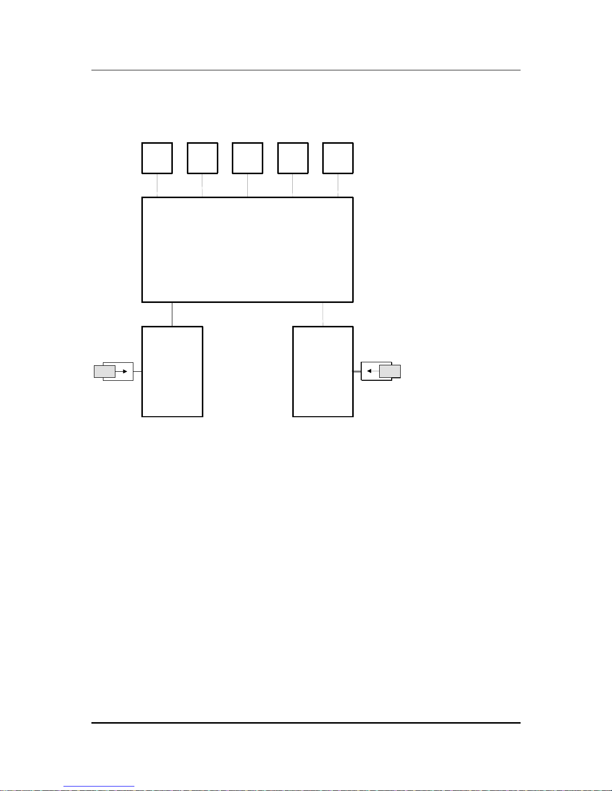
To realise the above features, a microprocessors switching has been developed
which controls the interaction of the various functional groups of coM.sat ISDN Basic.
These are illustrated in the following sketch.
USB
TE/
Sync
NT
LED DC IN
coM.s.a.t. ISDN Basic
Mainboard
GSM Module 1
SIM
SIMSIMSIMSIMSIMSIMSIMSIM
SIMSIMSIMSIMSIMSIMSIMSIMSIMSIMSIMSIMSIMSIMSIM
SIM
GSM Module 2
Figure 1: Functional Groups
Page 14
coM.sat ISDN Basic
created: page: file:
16/01/09 14 coMsat ISDN Basic Manual V2.7.doc
Note Protection Mark according to DIN 34!
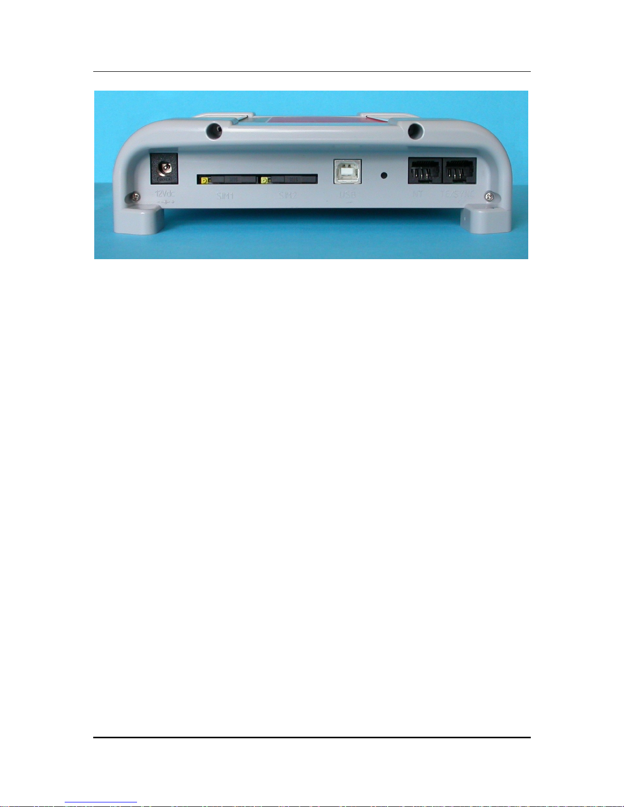
Figure 2: Front side of the coM.sat ISDN Basic
On the front side are located:
• the connector for the power supply
• 2 SIM card readers
• the connector for the USB port (USB-B)
• the jack for the NT connection (RJ-45)
• the jack for the TE connection or the synchronisation (RJ45)
Page 15
coM.sat ISDN Basic
created: page: file:
16/01/09 15 coMsat ISDN Basic Manual V2.7.doc
Note Protection Mark according to DIN 34!
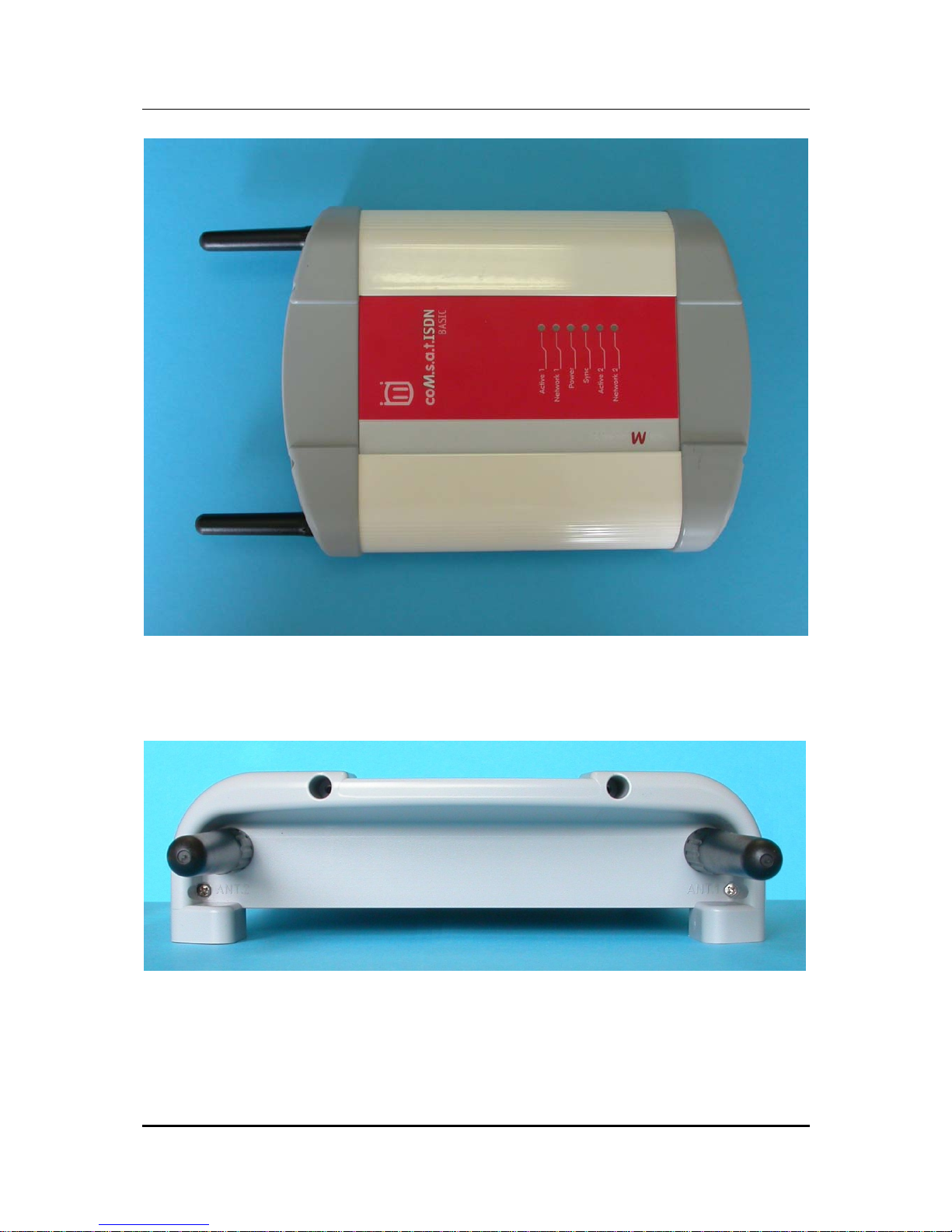
Figure 3: Top side of the coM.sat ISDN Basic
On the top side, there are the LED control indicators.
Figure 4: Rear side of the coM.sat ISDN Basic
On the rear side, there are the two RF- (SMA) connectors for the antennas, with
antennas screwed in.
Page 16

coM.sat ISDN Basic
created: page: file:
16/01/09 16 coMsat ISDN Basic Manual V2.7.doc
Note Protection Mark according to DIN 34!
The connections and significance of the LED’s are labelled to prevent errors.
Before starting up the device, the SIM cards must be inserted into the provided
holders. Two 3V SIM cards are required for full channel availability, but usage with
one SIM card is possible.
To insert the SIM cards in the device, first push in the round yellow button next to the
cardholder with a blunt, thin tool and then remove the cardholder. The SIM card is
then placed in the cardholder and inserted into the card reader together with its
holder. The contact area of the cardholder must be facing the rear of the device.
Attention: When pushing in the card, ensure that it does not fall out of the cardholder
and that the card is correctly inserted in the cardholder guides. The device requires
3V SIM cards for operation!
3.1 Starting up the device
The SIM cards should be inserted into their reader slot first. Then the necessary
cables are connected: Connection to the TC system as NT or TE, a connection to the
PC's USB port on which the coMsat.exe application is installed, and finally the
antenna cables.
Note 1: The GSM modules used in the coM.sat ISDN Basic for communication via
the GSM network operate with an internal voltage of 3V. Therefore, for proper
operation, SIM cards that can still operate with a working voltage of 3V must be used.
All new SIM cards usually fulfil this requirement. If older cards (designed for a voltage
of 5V) are used, the device possibly cannot log into the network - despite input of the
correct PIN - because the SIMs cannot operate correctly at a voltage they weren't
designed for.
Note 2: When looking at the front of the device, the left-hand SIM card is assigned to
channel 1 and the right-hand card to channel 2.
Once it has been installed, the device can be switched on by inserting the power
jack. This is indicated by the green LED which is labelled “Power“.
All the relevant parameters in the device are deleted in the factory before delivering
the coM.sat ISDN Basic, so that it must be set for the individual installation.
Therefore, when installing the TA for the first time, it must be configured using the
coMsat.exe application. To do this, a USB data link must be established between the
coM.sat ISDN Basic and the PC on which the application is installed.
Page 17
coM.sat ISDN Basic
created: page: file:
16/01/09 17 coMsat ISDN Basic Manual V2.7.doc
Note Protection Mark according to DIN 34!
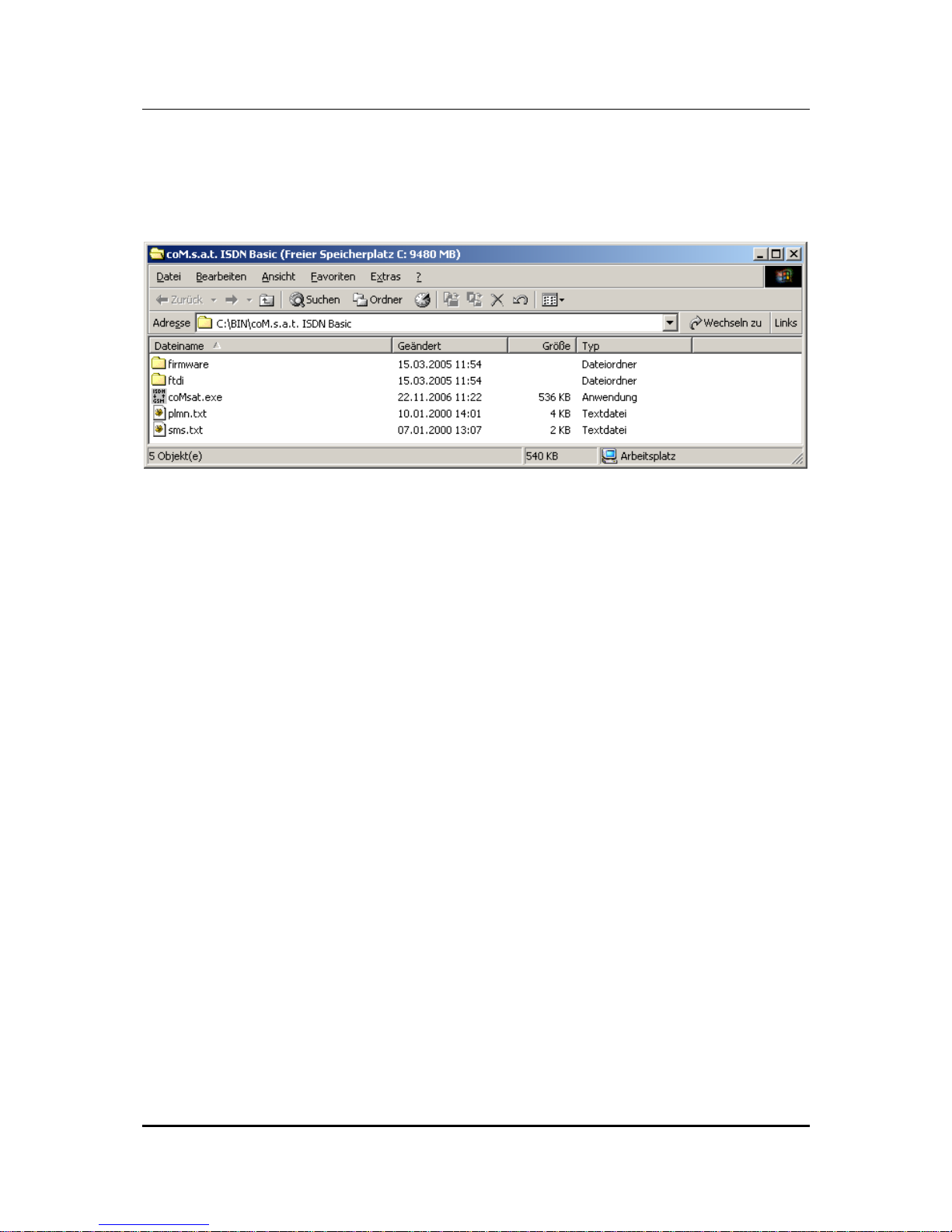
3.2 Installation of the coMsat.exe application
The coMsat.exe Windows® application is used to configure the coM.sat ISDN Basic.
It is copied into a suitable directory on a PC together with two text files:
Figure 5: coMsat.exe Installation
The coMsat.exe application can now be executed from this directory or via a
symbolic link that can be created manually e.g. on the desktop. A free USB port on
the PC is required for operation with the coM.sat ISDN Basic.
coMsat.exe needs a virtual COM port to access the ISDN Basic. To install it, the
current user must have administrator rights and the contents of the FTDI folder must
be stored in a suitable directory. If the ISDN Basic is attached to the PC for the first
time, the Windows® hardware assistant automatically reports a new device. It asks
for the installation files contained in the FTDI folder. After installation is completed, a
new virtual COM port has been added, e.g. COM3. This port must be used in
coMsat.exe.
The virtual device driver is supplied by Future Technology Devices International Ltd.,
the manufacturer of the USB/RS 232 converter used in the ISDN Basic. If another
driver is required, it can be obtained from www.ftdichip.com. The driver for FT232BM
must be used. The following four files in the FDTI distribution must be replaced by
those shipped with the ISDN Basic:
• FTDIBUS.INF
• FTDIPORT.INF
• FTDIUN2K.INI
• FTDIUNIN.INI
Page 18

coM.sat ISDN Basic
created: page: file:
16/01/09 18 coMsat ISDN Basic Manual V2.7.doc
Note Protection Mark according to DIN 34!
3.3 Configuration of the coM.sat ISDN Basic
The coM.sat ISDN Basic is configured with the aid of the coMsat.exe Windows®
application.
After starting the application by double-clicking the application’s icon, the main
application window is opened. Several file cards are displayed which control the
various functions. These are supplemented by the typical Windows® application
menus, such as File, Connection, Configuration, Info, Firmware, Terminal,
Monitor, View, and Help and a symbol bar for quick access to the New, Open,
Save, Login, Logout, Load/Save Configuration, Load Monitor, Load Status and
About commands.
Various function groups are arranged on the file cards so that they form meaningful
units. These are:
• Interface
• ISDN Cfg
• GSM Cfg
• Routing
• Incoming Calls
• Outgoing Calls
• Fax / Data
• Statistics
• Voice
• Unconnected Calls
• Diversion
• Virtual PBX
• Clock
• Channel 1
• Channel 2
• Info
• SMS
• Diversion
• Terminal
• Monitor
Note: The statistics, voice announcement, unconnected calls and diversion functions
are only activated if there is a valid Basic Pro license (see 3.3.15). The virtual PBX
functions are only activated if there is a valid virtual PBX license (see 3.3.12.6).
Page 19
coM.sat ISDN Basic
created: page: file:
16/01/09 19 coMsat ISDN Basic Manual V2.7.doc
Note Protection Mark according to DIN 34!
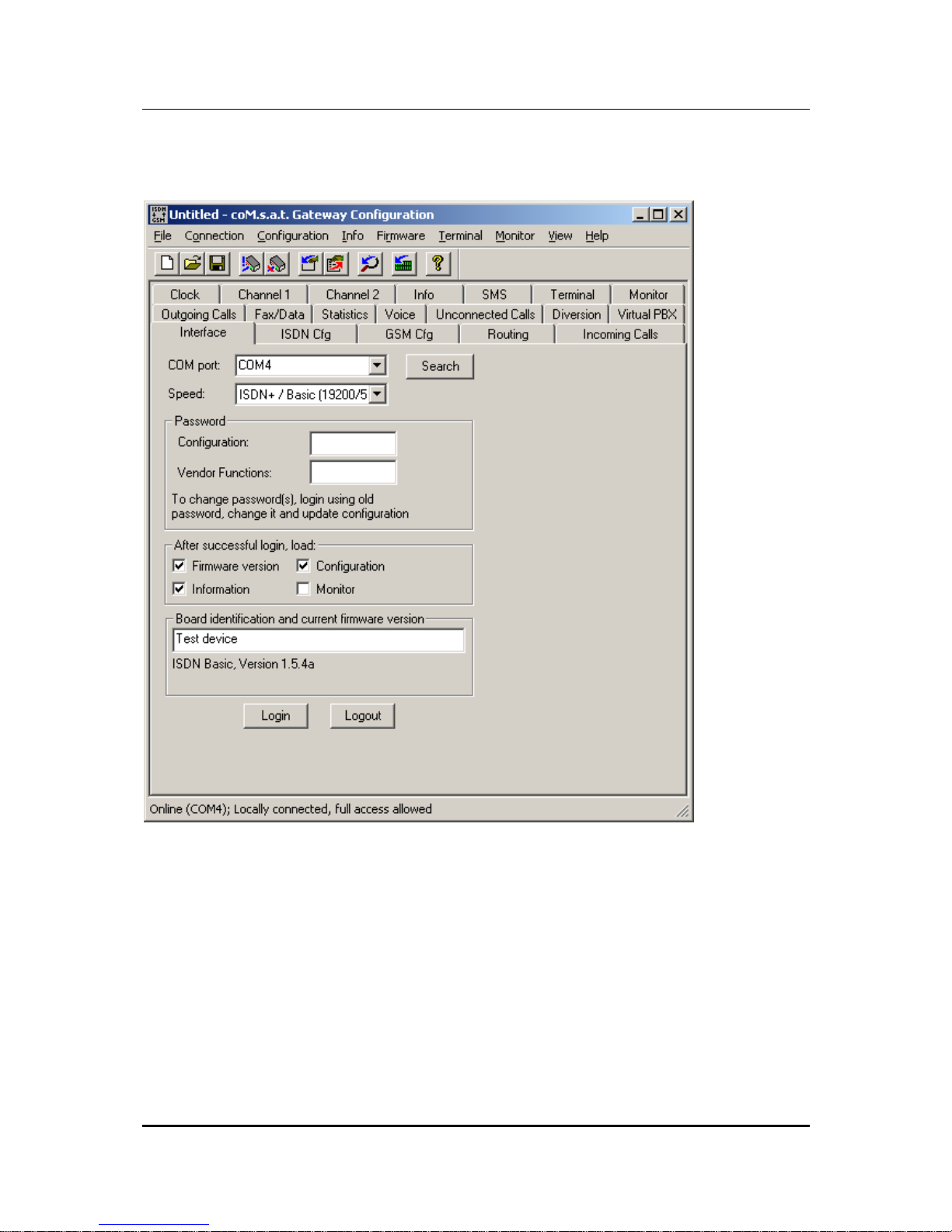
3.3.1 Interface
Figure 6: Interface
After starting the coMsat.exe application, the connection to the device is made via
the "Interface" tab. Upon clicking the tab marked "Interface" it will come to the
foreground and its contents will become visible.
The PC interface which shall be used for the data link to the coM.sat ISDN Basic is
selected using the "COM port" drop down list box. It is also possible to let the
application choose the port itself, using the "search" button. Should the application be
unable to find a connected coM.sat ISDN Basic, it will issue the message "No device
found!".
Page 20

coM.sat ISDN Basic
created: page: file:
16/01/09 20 coMsat ISDN Basic Manual V2.7.doc
Note Protection Mark according to DIN 34!
Many functions require an authentication of the user. This is done by clicking on the
"Login" button also located on this tab. The authentication is removed by clicking the
"Logout" button. The termination of coMsat.exe automatically removes
authentication. Therefore explicit logout is only required if coMsat.exe remains
connected to the ISDN Basic after the user leaves it.
To prevent unauthorised persons from logging into the TA and altering the
configuration, at least the configuration password should be entered in the
“Password“ box. Each password consists of max. 19 alphanumeric characters. The
various function groups within the coM.sat ISDN Basic coMsat.exe application are
then accessible with differing protection.
Users who do not know either of these passwords can carry out all the unprotected
functions on the device. They connect to the device by calling up “Connection” on
the menu bar and calling up ”Go Online” in the menu that opens, or simply use the
desired function. The applications then connects to the coM.sat ISDN Basic. In this
mode, the device configuration can be read, but not altered. SMS can be sent and
received and any SMS received can also be read. The same procedure applies to
remote access to the device.
However, the configuration settings can only be altered by logging in with a
configuration password. Then all configuration data can be read out, amended and
resaved. The ”Vendor Functions” password makes further functional blocks
accessible, via which the various network operators can be authorised or excluded.
If a password is entered, this password is transferred to the TA together with the
configuration data. The next time the TA is logged into, the password must first be
entered in the relevant box.
A password can be deleted or altered after logging in by deleting the relevant box for
the password or entering another password. The new password is then valid after the
next update of the configuration.
On the interface tab, the user can specify additional actions after successful login.
The firmware version, the configuration of the device, the status information and the
monitor can be loaded. The first three are activated by default on every execution of
the software.
The firmware name and version (if loaded) and the user configurable device
identification are also displayed on the interface tab. The device identification is
stored in the device on updating its configuration and displayed on the interface tab
after reading the configuration. Its purpose is to allow easy recognition of different
devices in a multi-device installation.
The configuration data of one or several devices can be saved as usual in
Windows®. The files contain the configuration, the firmware ID, the device
information and the monitor contents, if these have been loaded before.
At the bottom of the coMsat.exe window there is a state bar which displays the
Page 21
coM.sat ISDN Basic
created: page: file:
16/01/09 21 coMsat ISDN Basic Manual V2.7.doc
Note Protection Mark according to DIN 34!
current actions. The state of the link (online/offline) and the port of the PC via which
the data is transmitted when a link is made (e.g. “Online (COM 1)”) is displayed on
the left-hand side of the bar.
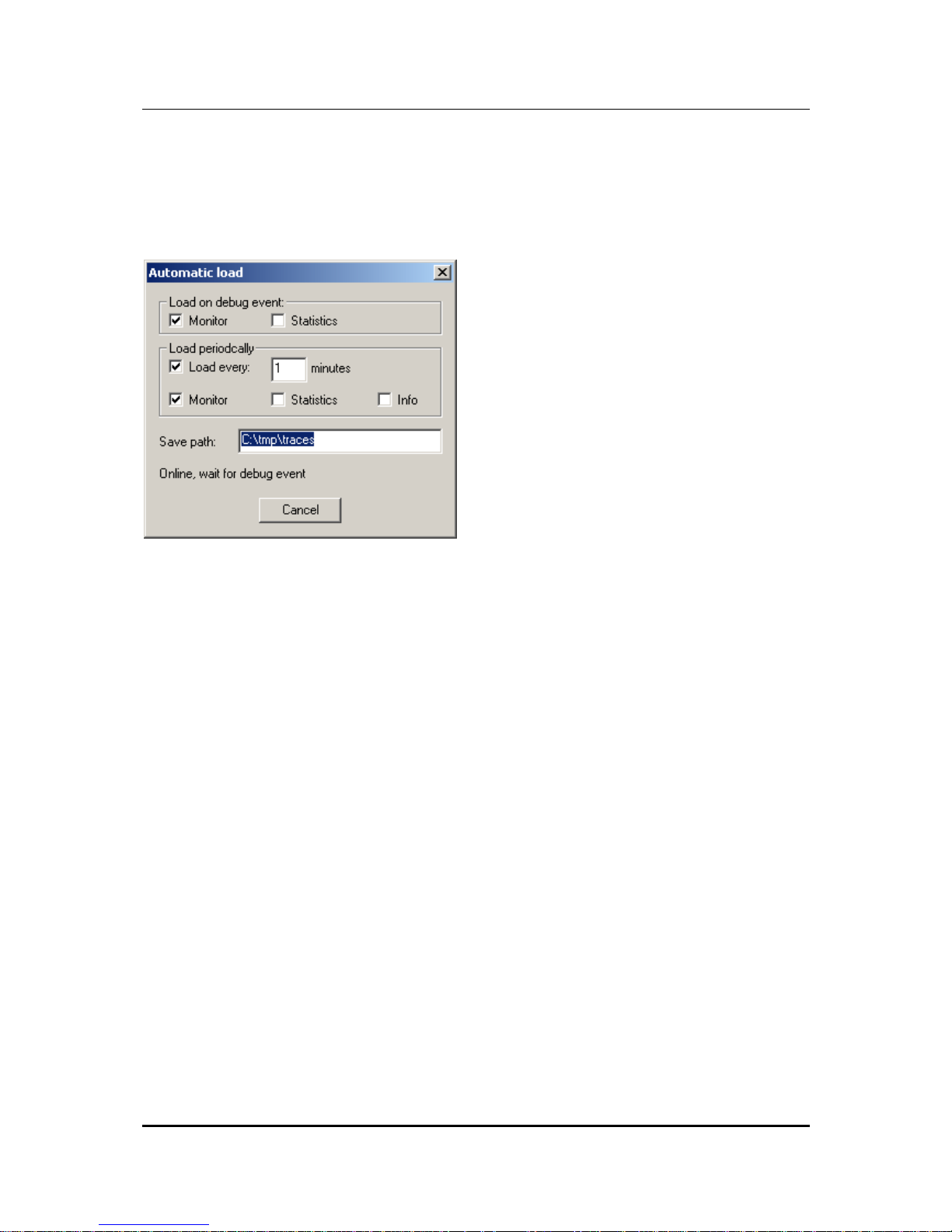
The ”Connection” menu contains another command, i.e. ”Automatic Load”. This
command opens the following dialog:
Figure 7: Automatic Load
As long as this dialog is open, coMsat.exe checks the messages from the device
and starts an automatic load if it reports a restart. It can load the monitor and the
statistics as selected by the first two options.
The load process can also be started periodically. To enable this, the option “Load
every … minutes” must be activated and the period set as desired. The automatic
can load the monitor, the statistics and the status information as selected by the
options. The statistics can only be loaded if the license for extended funktions is
available, otherwise the option is disabled.
If the automatic load is done for monitoring a long period, the load timeout should last
3 – 5 minutes in order not to loose information. If only statistics is loaded, 1 hour is
sufficient. To load the statistics, a login must be possible so the passwords must be
entered correctly. The automatic load function logs in before loading the statistics,
even if already logged in. This is done because a restart might have caused a logout
and then the statistics could not be loaded anymore.
Page 22
coM.sat ISDN Basic
created: page: file:
16/01/09 22 coMsat ISDN Basic Manual V2.7.doc
Note Protection Mark according to DIN 34!
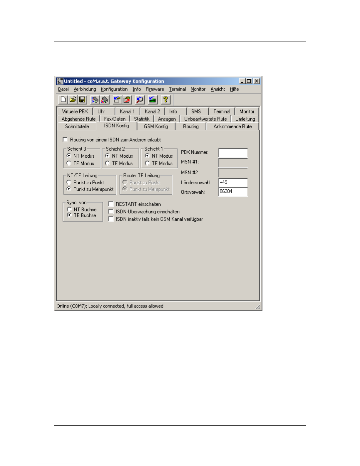
3.3.2 ISDN Configuration
Figure 8: ISDN Configuration
The settings required for operation with the telephone system are made in the "ISDN
Cfg" tab. When configuring the ISDN link, layers 1 to 3 are independently set for
operation of the coM.sat ISDN Basic in NT or TE mode.
NT-Mode operation
In this mode the device presents itself to the telephone system as the ISDN network
operator's network terminator. The connection to the coM.sat ISDN Basic is set up as
a point-to-point or point-to-multipoint connection.
Page 23

coM.sat ISDN Basic
created: page: file:
16/01/09 23 coMsat ISDN Basic Manual V2.7.doc
Note Protection Mark according to DIN 34!
If the telephone system additionally has a fixed network connection and it reports too
many errors (frame slips, bit slips), a synchronisation may be necessary. These types
of errors are unimportant for voice communications. However, in mostly larger TC
systems with more elaborate trouble shooting procedures, problems can occur during
operation that can cause this “faulty“ port being switched off. This can be avoided by
synchronisation. In this case, the synchronisation input of the coM.sat ISDN Basic is
connected directly with the system port (fixed network). The synchronisation clock is
then derived from this signal.
If an optional add-on board is employed, it is possible to derive the synchronization
clock from the NT port rather than the synchronization port. The parameter field
labelled "Sync from" defines which port is used for synchronization. If the
synchronization on the NT port is selected, the connected TE device must use a
clock on that port synchronized to another source. Note: Since the presence of the
add-on board is not detected, the parameter field is always enabled in NT mode even
if the add-on board is not employed. See also chapters 4.1 and 4.3.
The PBX number entry also depends on the telephone system. Some systems do not
require an entry here. As the entry of Multiple Subscriber Numbers isn't necessary in
NT-mode, their respective boxes are inactive.
TE-Mode operation
If the coM.sat ISDN Basic is to be used in TE-mode, that is like a simple extension,
then click the corresponding radio button for layer 3. Layers 2 and 1 will automatically
be set to TE-mode. In this mode (operating on the telephone system's internal S0
bus) there is usually a point-to-multipoint connection. Therefore the line type is
automatically set to this type of connection.
It is also often necessary to identify those extensions (Multiple Subscriber Numbers 1
and 2) via which the device is identified by the telephone system. Both GSM
channels may be addressable by the same MSN if supported by the telephone
system. If at least one MSN is empty, the device accepts any called party number
and uses that number for the outgoing call. This means that the MSN is dialled via
GSM, which is usually not desired. This function is useful if there is a diversion or VIP
number programmed for each possible MSN, so that the MSN is converted into a
valid GSM number.
If used in TE-mode, as terminal equipment, no synchronisation is necessary.
Router operation
If the coM.sat ISDN Basic shall be able to route calls from one ISDN port to the
other, then activate the box labelled “Allow routing from one ISDN port to the
other”. Layers 3, 2 and 1 will automatically be set to NT-mode because this reflects
the setting of the ISDN port labelled “NT”. The line type automatically changes to
point-to-point connection. The mode of layers 2 and 1 and the line type may be
changed subsequently, but layer 3 of the NT port remains in NT mode, layers 3 to 1
of the TE port always operate in TE mode, and the line type setting applies to both
ports.
The PBX number entry also depends on the telephone system. Some systems do not
require an entry here. As the entry of Multiple Subscriber Numbers isn't necessary in
router mode, their respective boxes are inactive.
Page 24

coM.sat ISDN Basic
created: page: file:
16/01/09 24 coMsat ISDN Basic Manual V2.7.doc
Note Protection Mark according to DIN 34!
The ISDN line monitoring is activated via the “Enable ISDN Watchdog” option box.
In this case, if faults are registered in the ISDN layers 1 or 2, a warm restart is carried
out approx. every 100 seconds.
The “Enable Restart” checkbox defines whether or not the coM.sat ISDN Basic
sends the telephone system a restart command after a cold start or reset. Usually
this option need not be set. It can be set to terminate any active calls after a restart of
the device, but there are also TC systems that do not react on restart messages and
thus make the coM.sat ISDN Basic inaccessible until a timeout terminates the restart
procedure.
The option “ISDN inactive if no GSM channel available” can be enabled to activate
the ISDN port (either NT or TE depending on the mode) only if at least one GSM
channel is ready for calls. Otherwise the ISDN is deactivated and a PBX can use this
information to route calls to other ports. This option is deactivated in router mode,
because otherwise it would not be possible to make calls to PSTN if no GSM channel
is available.
The country and area code are set in separate input boxes. The country code is the
international dialling prefix (e.g. “+49”). The area code is usually the prefix for phone
numbers in the same town that the TA is located and is therefore omitted when
calling a number in the same area (e.g. “06204”). Entering these numbers at this
point saves you the effort of entering them during later definitions of number lists
(e.g. Net Access Numbers).
If not otherwise specified, the ISDN Basic assumes that international calls start with
“00” (or “+”) and national calls start with “0”. These settings can be modified by
appending the correct setting to the country and area code separated with a slash
(e.g. “+1/011” as country code and “…/1” as area code for USA and Canada).
The current configuration of the coM.sat ISDN Basic can be enquired by clicking on
“Configuration“ in the menu bar and then selecting “Query“ from the menu.
Alternatively, the short cut keys
<Alt> <C>
and
<Q>
can be used or the button “Query Configuration” in the toolbar can be pushed.
After entering a new configuration or altering the current configuration, this can be
saved via the “File“ menu or can be transferred to the coM.sat ISDN Basic via the
USB data link. This is done either via “Update“ in the “Configuration“ menu or by
pushing the toolbar button “Update Configuration” or by entering the relevant keys on
the keyboard.
A configuration file that has already been stored can be loaded again using the file
menu and transferred to the device as described.
Page 25
coM.sat ISDN Basic
created: page: file:
16/01/09 25 coMsat ISDN Basic Manual V2.7.doc
Note Protection Mark according to DIN 34!
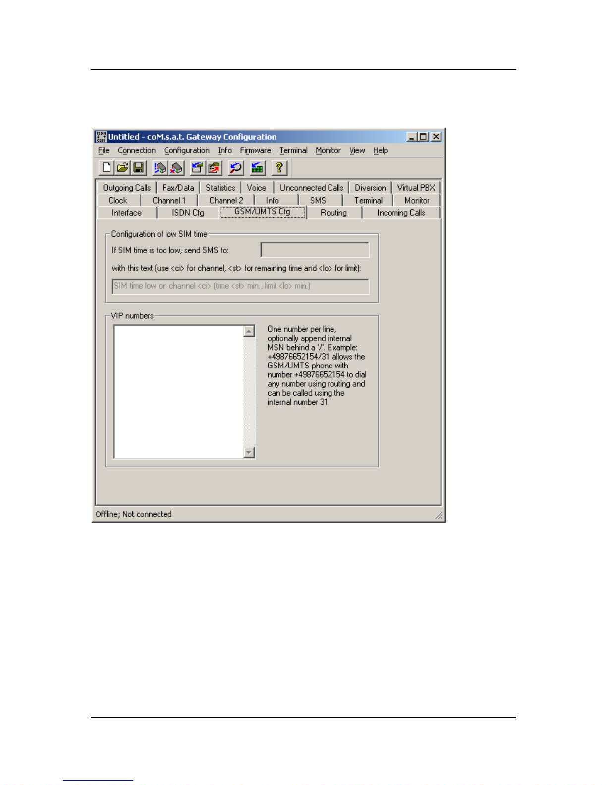
3.3.3 GSM/UMTS Configuration
Figure 9: GSM/UMTS Configuration
This page is used to configure GSM/UMTS specific options.
The coM.sat ISDN Basic implements a time based supervision of prepaid credits.
The credits themselves are dynamically programmed using the command “Set
Prepaid Time“ in menu “Info“, which is described in chapter 3.3.15. Each channel is
programmed a separate threshold, see chapter 3.3.14. If the credit falls below that
threshold, the channel is not used anymore. The GSM configuration on this page
configures additional behaviour in this case.
A GSM phone number can be programmed which shall receive an SMS if the credit
becomes low. If no number is programmed, no SMS is sent. If a number is
Page 26

coM.sat ISDN Basic
created: page: file:
16/01/09 26 coMsat ISDN Basic Manual V2.7.doc
Note Protection Mark according to DIN 34!
programmed, the second input field determines which text is sent with the SMS. This
text allows three place holders:
• <ci>: Is replaced by the number of the channel with low credit
• <st>: Is replaced by the remaining time credit
• <lo>: Is replaced with the programmed threshold
The VIP number list “VIP numbers” contains GSM phone numbers that get a special
treatment. Each line contains a phone number and may also contain an MSN in the
format <GSM number>/<MSN>. The MSN may be used to define short numbers for
the members of the VIP list. If this MSN is called from any source (i.e. NT, TE or
GSM), the call is connected to the associated GSM phone number. If a call comes in
from a VIP number, the associated MSN is transmitted as calling party number in the
ISDN messages.
VIP users always have the right to dial in even if the channel’s dial in option is
switched off (“Call Default”, see 3.3.14). This allows to define a specific user group
that may dial any number while normal users only call the default extension.
VIP users also use the routing function (see 3.3.4). While normal users calling from
GSM are always connected to the PBX, VIP users may also call to PSTN or GSM
depending on the called number and the programmed routing.
If a VIP number is called, the calling party number (the number belonging to the SIM
card) is always shown to the VIP user, even if the channel in use has the option CLIR
enabled, thus suppressing the number presentation. This does not enable the use of
the return call handling in this case, because then a VIP won’t be able to use the
VPBX anymore if a return call is stored for him.
The functions of the virtual PBX are also accessible to VIP users (see 3.3.12). Thus
all GSM users contained in this list can use all functions normally available only to
PBX extensions. Therefore these phone numbers are also called virtual extensions.
Note: The device uses the country and area code settings for the GSM number so
that only one notation of a number need to be entered in the list.
Page 27
coM.sat ISDN Basic
created: page: file:
16/01/09 27 coMsat ISDN Basic Manual V2.7.doc
Note Protection Mark according to DIN 34!
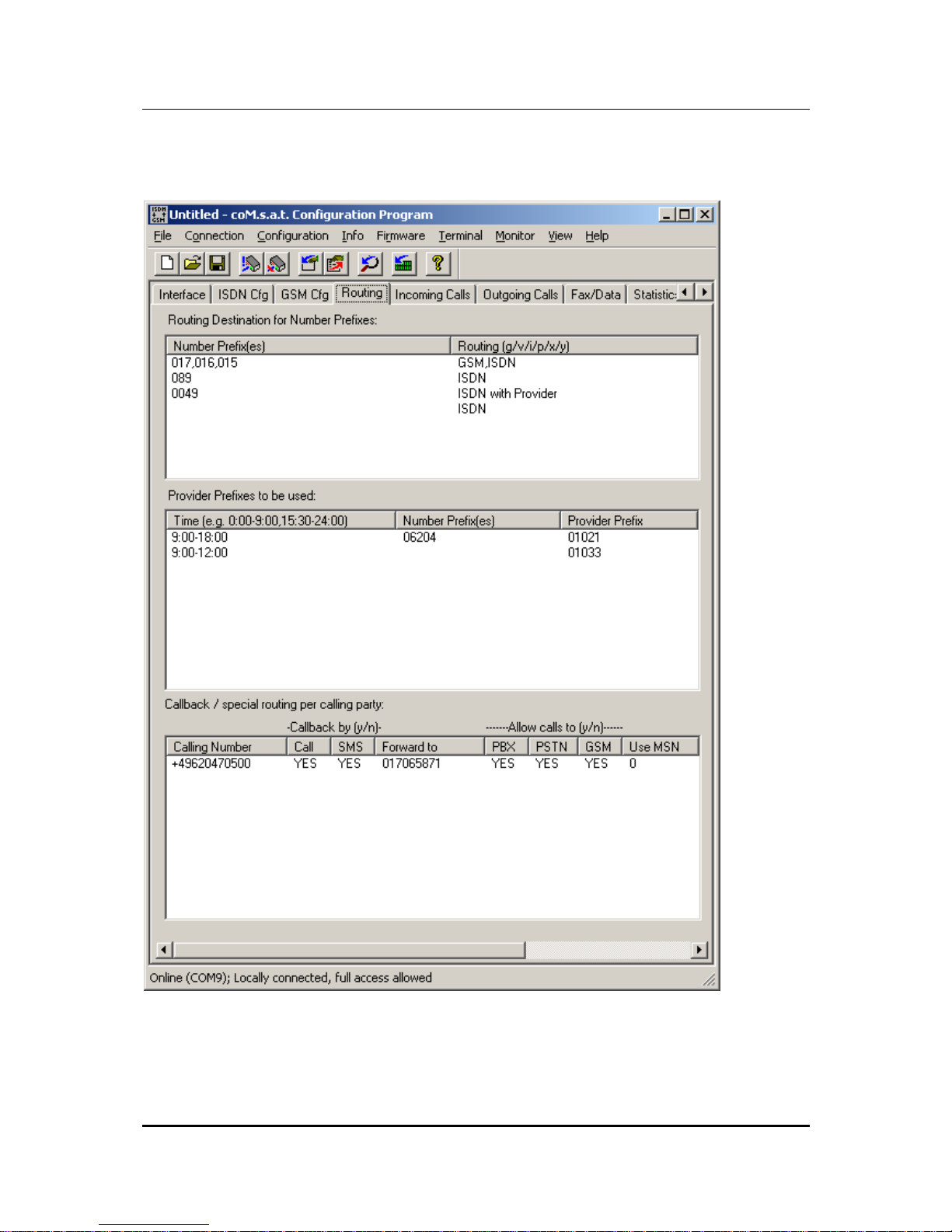
3.3.4 Routing
Figure 10: Routing
Page 28

coM.sat ISDN Basic
created: page: file:
16/01/09 28 coMsat ISDN Basic Manual V2.7.doc
Note Protection Mark according to DIN 34!
3.3.4.1 Routing according to dialled number
The table “Routing Destination for Number Prefixes“ determines if GSM (with or
without provider) or ISDN (with or without provider) is to be used. Special cases also
require the setting of a routing for calls to the PBX (with or without provider).
Example:
Number Prefix Routing
017, 016, 015 GSM, ISDN
089 ISDN
0049 ISDN with Provider
ISDN
This table is parsed from top to bottom, comparing the prefix with the called number.
If the number’s first digits match the given prefix, the routing is evaluated. If “GSM” is
specified, a GSM channel is selected according to the “Net Access Numbers“
settings, optionally inserting a provider. If “ISDN” is specified, the call is routed to
PSTN, again allowing the insertion of a provider prefix, just like the specification of
“PBX” which causes a routing to the TC system. If more than one route ia specified
and the first one is not able to route to call, the second option is evaluated. If e.g.
“GSM,ISDN” is specified and there is no GSM channel available at the moment, the
call is routed to ISDN (“fallback”). If in this case only “GSM” would have been
specified, the call would be rejected.
The example above causes the following behaviour:
• All calls to typical (german) GSM numbers are routed via GSM if possible, and
via ISDN otherwise
• All calls to Munich (089) are routed via PSTN without provider prefix
• All other calls to german numbers (+49) are routed via PSTN with a provider
prefix
• All other calls are routed via PSTN without provider
In addition to numbers, the place holder “?“ can be used to specify any number. This
is especially useful if numbers can only be distinguished by their length. This applies
e.g. to internal MSNs and local area numbers. The following example assumes that
all internal MSNs are two digits long:
Number Prefix Routing
017, 016, 015 GSM
??? ISDN
?? PBX
This routing table works like this: All GSM numbers are routed via GSM. If any
number with only two digits is dialled, only the entry number 3 matches, because all
other entries require at least 3 digits. All numbers with more than two digits not
matching the first line are routed to the ISDN network.
Page 29

coM.sat ISDN Basic
created: page: file:
16/01/09 29 coMsat ISDN Basic Manual V2.7.doc
Note Protection Mark according to DIN 34!
The table is split into two columns and the entries are directly edited in the list box. A
double click on an entry makes it editable. By using the “Page Up” and “Page Down”
keys, the edit field can be moved to the next or previous column. The cursor up and
down keys move the edit field one line up or down in the same column.
If the list box has the input focus but no entry is edited, the insert key allows to create
a new line above the first currently selected line. All selected lines can be deleted
using the delete key. Ctrl-C copies selected lines to the clipboard just like Ctrl-X
which also removes the lines afterwards. Ctrl-V inserts lines from the clipboard above
the first selection or at the bottom of the table if none is selected. A selection can be
removed by left click with pressed control key as usual in multiple selection list boxes.
Tab and shift-tab can be used to jump to the next or previous dialog element, as
usual.
The second column only allows to use the keys “i”, “g”, “p”, “v”, “x”, “y”, backspace,
cursor left/right and delete. “i” inserts “ISDN”, “g” inserts “GSM” and “x” inserts “PBX”
at the current insert position. “p”, “v” and “y” do the same with the option of inserting a
provider prefix. The cursor can only be positioned at the beginning and end of words.
Delete and backspace always delete complete words.
Empty lines are removed automatically before the configuration is updated.
3.3.4.2 Selection of providers by time and number
The table “Provider Prefixes to be used“ defines which provider should be used for
those numbers that are routed with provider specified in the first table. This table is
ignored otherwise.
Example:
Time Number Prefix Provider Prefix
9:00 – 18:00, 20:00 – 22:00 0241,0621 01021
9:00 – 12:00 01033
12:00 – 18:00 01013
18:00 – 20:00 01051
0:00 – 24:00 01070
This table is parsed from top to bottom, comparing the current time to the times
specified in the first column and the called number to the prefix in the second column.
An empty entry in the number prefix column matches any number. If both entries
match, the provider specified in this line is used.
The first line in this example defines a specific prefix for specific area codes. The last
line in this example causes all numbers not matching one of the entries above to be
routed using the prefix 01070.
If no entry matches, the call is rejected.
Page 30

coM.sat ISDN Basic
created: page: file:
16/01/09 30 coMsat ISDN Basic Manual V2.7.doc
Note Protection Mark according to DIN 34!
This table is displayed in three columns that are edited the same way as the first
table, except that there is no special editing as in the second column of the first table.
3.3.4.3 Callback Table and special routing
The last table on this page, which is only activated if there is a valid Basic Pro license
(see 3.3.15), allows to call back special GSM numbers on request. The callback can
be initiated either by a call (which is rejected) or by an SMS, depending on which
method is allowed in the columns “Call“ and “SMS“ by entering “yes“. If a callback by
SMS is allowed, it is sufficient to receive an SMS from that GSM number. If the SMS
contains a number, it is stored as desired number to be called.
If the callback is accepted by the GSM user, he usually gets a dial tone and can dial
a number to one of the allowed destinations. If the channel used does not allow
dialling (“Call Default“), there is no dial tone and the call is forwarded to the number
configured in column “Forward to“. If the callback was done due to a received SMS
and the SMS contained a number, there is no dial tone either and that number is
called.
If one (and only one) line has an empty “Calling Number“, this line matches any call
without CLIP. These callers never get a dial tone but are always forwarded to the
number configured in column “Forward to“.
This table can also be used to configure a default number different from that in the
channel settings. The number configured in column “Forward to“ supersedes the
number of the channel settings and is called if that special GSM user is calling and
nothing is dialled or dialling is not allowed. This is also true if no callback is allowed,
so that the entry only assigns a different default number.
Additionally, the table can prevent certain callers from calling specific destinations. If
a calling party number matches an entry in the callback table, those destinations in
the routing table not allowed by this entry are removed from the possible routes.
3.3.4.4 Automatically inserted country and area codes
The own country and area code is programmable on the dialog page named “ISDN
Cfg“. This enables the router to find matches in the tables even if the table entries are
specified with these codes and called numbers are lacking them. It is also possible to
specify the tables without these codes and called numbers with these codes will still
match. This eliminates the need for specifying all possible number representations.
Page 31

coM.sat ISDN Basic
created: page: file:
16/01/09 31 coMsat ISDN Basic Manual V2.7.doc
Note Protection Mark according to DIN 34!
3.3.5 Incoming calls
Figure 11: Incoming calls
The configuration for incoming GSM network calls is set up via the “Incoming calls“
card. First set up how ”Calls without CLIP” are dealt with. These calls can either be
transferred to a particular extension (”Call Default No. ”), which is determined during
configuration of the GSM channels, or rejected, or dealt with in the same way as all
other calls (”Not Special”).
The dial in behaviour on calls from GSM is further specified by the option ”Dialling
Mode. Overlapped” means that incoming calls are immediately reported to the PBX
without any dial information. The PBX requests more information and the call is
Page 32

coM.sat ISDN Basic
created: page: file:
16/01/09 32 coMsat ISDN Basic Manual V2.7.doc
Note Protection Mark according to DIN 34!
connected. Each dialled digit is immediately forwarded to the PBX which terminates
the dial procedure as soon as it has enough information to call an extension.
This is different if ”En-bloc” dialling is selected. Then the coM.sat ISDN Basic
connects the call without contacting the PBX. This is done after the called number
has been completely received. Since the device does not know the numbering plan
of the PBX, it can not determine from the called digits if a number is complete. This is
detected either by having received as much digits as specified by ”Max. Length” or if
no more dial information is received for as long as configured in ”Incoming call dial
timeout” in the channel settings. If less than ”Min. Length” digits is received, the call
is rejected.
The option ”En-bloc” has to be used if the PBX does not support overlapped dialling.
If no PBX is connected, but only some phones on a bus, this is almost always
necessary. If using overlapped mode and incoming calls which should be able to dial
do not get a dial tone, but one or more phones start ringing immediately, this
indicates that the ”En-bloc” option is needed.
A further option (”Enable CLIP in TE Mode”) can also be selected in this card, but it
can only be accessed if the TE mode has been set. You can then choose whether
the caller’s number is to be transmitted or not. If this box is checked, the coM.sat
ISDN Basic tries to transmit the number calling from within the GSM network -
provided the telephone system it is connected to supports this feature.
The option ”Enable Maintenance Calls” determines the handling of GSM data calls.
If the option is switched off, all data calls are ignored. If it is enabled, these calls can
be connected in order to perform remote maintenance. If the list ”Maintenance Calls
from” is empty, all data calls are connected. If there are numbers in this list, only data
calls from these numbers are connected for remote maintenance.
Callers can also be rejected by the coM.sat ISDN Basic. The relevant phone
numbers are entered in the “Reject Callers“ list box. Only one phone number is
entered in each row. The number of the caller may be longer than the number in the
list, so multiple callers with the same prefix can be rejected with a single entry.
The telephone numbers of callers that are to be transferred directly to specific
extensions can be entered in another list (Direct Calls from / to). The callers must
have activated Calling Line Identification Presentation (CLIP) in their phone in order
to utilise this feature. The entries must be entered in the form: <international phone
number><national dialling code><phone number>/<MSN>.
Example: +4962171481430/22
Note: Both lists use the country and area code settings so that only one notation of a
number need to be entered in the lists.
The length of the lists only depends on the amount of internal memory. A storage
area of 32 kByte is available for the lists and configuration parameters. A 10 - digit
number occupies 10+1 bytes of memory, moreover a few additional bytes are
needed for the termination of the lists. It is up to the user to decide which lists are
important and need to be enforced. It is entirely possible to use one and only one of
Page 33

coM.sat ISDN Basic
created: page: file:
16/01/09 33 coMsat ISDN Basic Manual V2.7.doc
Note Protection Mark according to DIN 34!
the definable lists with the maximum length or to use all lists with an accordingly
reduced length. In the latter case the lists each have a length of approximately 70
entries.
Page 34

coM.sat ISDN Basic
created: page: file:
16/01/09 34 coMsat ISDN Basic Manual V2.7.doc
Note Protection Mark according to DIN 34!
3.3.6 Outgoing calls
Figure 12: Outgoing calls
A separate card is provided for the configuration of outgoing calls in the same way as
for incoming calls.
The type of speech communication is selected in the “Bearer Capability“ box of this
card. The “Accept Speech“ option should then be selected if the coM.sat ISDN
Basic is connected to a telephone system to which only ISDN telephones are
connected. If analogue telephones are also used, both options should be selected.
On the other hand, no speech communication is possible if both options are
Page 35

coM.sat ISDN Basic
created: page: file:
16/01/09 35 coMsat ISDN Basic Manual V2.7.doc
Note Protection Mark according to DIN 34!
deactivated. This makes sense if only SMS is to be exchanged.
The assignment of the B-channels to the GSM channels is then defined in the “B to
GSM Channel“ box. Fixed assignment determines that the first B channel is
assigned to the first GSM channel. Fixed assignment of the channels can be useful if
e.g. different network providers are to be used for the two GSM channels. If the
channels are freely assigned, the call is assigned to the first free channel. If one
channel is busy, the other is used. In the case of free channel allocation there is the
additional option "Use channels alternatingly". The GSM channels are selected
alternatingly. This feature can be used to balance the load (the cost) evenly between
channels. If this box is not checked, there will be a bias towards one channel!
The “Progress Indicator” setting influences the value of an ISDN information
element. The first value “Call is not end-to-end ISDN” informs the connected PBX
that its call uses a different network to be connected. The other value “In-band
information now available” informs the PBX that an announcement or a tone is
available and must be transferred to the calling user. This value is usually needed for
correct operation, whereas the first value may be needed by specific PBXs. If the
progress indicator causes a problem in the PBX, it is possible to switch it off
completely with the third option “Do not send progress indicator“.
The “Dial Timeout“ is the time that may pass between the last digit of the phone
number being dialled and the selection process is passed into the GSM network. This
time is usually set to 5 secs. It can be reduced to 1 second. The maximum possible
setting is 10 secs. The time between dialling the last digit and hearing the dialling
tone can be reduced by reducing this time.
Note: In some telephone systems, dialling can also be concluded by pressing the “#“
key. In this case there is no waiting time.
The “Send Alerting Message“ option is used to set whether the “Alerting“message
is generated by coM.sat ISDN Basic for calls to PBX. If this option is selected, the
“Alerting“ message is inserted by coM.sat ISDN Basic for an outgoing call after the
“Setup“. If the option is not activated, the “Alerting“message is suppressed and the
call is continued with “Call Proceeding“. Use of this option also depends on the
properties of the connected telephone system.
coM.sat ISDN Basic always generates the dialling tone (exchange dialling tone) itself
and transfers the ringing tone or the network provider announcements to the Bchannel. Whether the ringing tone or the network provider announcements from the
GSM network are used in the B-channel or the ringing tone generated by the
telephone system is used now depends on whether the “Alerting“ option has been
activated or is passive.
The “Enable DTMF in TE Mode“ option must be used if the coM.sat ISDN Basic is
connected to a PBX in TE mode which does not support overlapped sending of dial
information (which is the usual case). Then the GSM number is dialled with the aid of
DTMF tones.
The "March Root Tone" serves to bridge delays with a tone or sequence of tones in
order to prevent the impression that the line is "dead", particularly during the call
setup. The TC35i modules produce the “march root tone” on their own. If the tone of
Page 36

coM.sat ISDN Basic
created: page: file:
16/01/09 36 coMsat ISDN Basic Manual V2.7.doc
Note Protection Mark according to DIN 34!
the ISDN Basic is to be used, the tone of the TC35i module should be switched off.
The duration of the tone is set in the input box: 30 represents a tone of 3 seconds
duration.
The parameter "Dial Tone Delay" can be used in applications that rely heavily on
block dialling. Some PBXs do block dialling in two steps. First they initiate a call
without number so that the ISDN Basic generates a dial tone. Then they send the
called party number which stops the dial tone again. This can be prevented using
”Dial Tone Delay”, delaying the dial tone by multiples of 0.1 seconds. The dial tone
is only started if no dialled number is received during that time.
If the GSM network always uses the same length for its phone numbers, the
parameter “Max. No. Length” can be set to this length. This instructs the ISDN
Basic to start the outgoing call immediately after that number of digits have been
dialled, without waiting for timeout.
The March-Root-Tone generated by the TC35i module can be suppressed by
checking "Mute March Root Tone".
The option "Send SMS called party…" causes an SMS to be sent for calls from PBX
to GSM containing a configurable text where the MSN of the caller can be inserted
using the placeholder <msn>. This allows the called user to see who calls him during
an active or after a missed call.
The possible settings for outgoing calls are then rounded off by three lists.
The phone numbers that are not to be dialled are entered in the first list, e.g. very
expensive numbers that start with 0190x. If no country and area code is specified,
the phone number must be entered both with and without the dialling code to avoid
being able to call restricted numbers by using or ommitting these codes.
Example: 71481430
062171481430
+4962171481430
However, if the country code “+49” and the area code “0621” is configured, only one
entry of the three above is necessary.
The comparison of the numbers begins at the first position and need not match
completely. Entries in this list can therefore be prefixes.
The second list is used for entering the phone numbers that allow free calls, e.g. the
numbers that begin with the digits 0800. No charge impulse information is generated
for these numbers. The notes above also apply to this list.
The third list contains numbers or prefixes that shall always see the calling party
number when called (CLIP), even if this function is disabled (CLIR is enabled) for the
calling channel. This allows to enable CLIP and return call handling for specific
numbers (see 3.3.10).
Page 37

coM.sat ISDN Basic
created: page: file:
16/01/09 37 coMsat ISDN Basic Manual V2.7.doc
Note Protection Mark according to DIN 34!
3.3.7 Fax/Data
Figure 13: Fax/Data
This page allows the configuration of data and fax connections. Since the coM.sat
ISDN Basic has no built-in analogue modem, it is not possible to set up data or fax
connections via ISDN and therefore the options for these kind of calls are disabled.
The coM.sat ISDN Basic is able to exchange data and faxes by the use of a PC. In
this case, the connected PC must have suitable software for fax or data which is
ready to receive incoming calls. To enable this, ”Data Calls to PC” and/or ”FAX
Calls to PC” must be enabled. Then the coM.sat ISDN Basic behaves like an
analogue modem on its serial interface, i.e. incoming calls are reported with a ”RING”
Page 38

coM.sat ISDN Basic
created: page: file:
16/01/09 38 coMsat ISDN Basic Manual V2.7.doc
Note Protection Mark according to DIN 34!
indication. Following commands and data are directly transferred between PC and
GSM module so that it behaves as a fax class 1 modem for the PC.
Outgoing fax and data connections are always possible via the serial interface
without special configuration. If the dail command (ATD) is detected, this command is
given to a free GSM module regarding the net access numbers, and this module is
connected transparently to the PC, so that the PC again operates as if connected to
a fax class 1 modem. If the PC sent other commands immediately before the dial
command which are not processed by the coM.sat ISDN Basic itself, these
commands are also sent to the GSM module before dialling. Further information on
fax and data connections can be found in chapters 4.5 and 4.6.
Note 1: The SIM cards used must support fax and data calls.
Note 2: If fax and/or data shall be exchanged with the use of a PC, but the PC
software did not activate the serial interface, these calls will be rejected.
Page 39

coM.sat ISDN Basic
created: page: file:
16/01/09 39 coMsat ISDN Basic Manual V2.7.doc
Note Protection Mark according to DIN 34!
3.3.8 Statistics
Figure 14: Statistics
The statistic functions are intended for the storing of call data. Incoming and outgoing
calls are registered. The information is stored in two different files. Due to the limited
memory space, call data is stored until the available memory is almost used up.
When it becomes obvious that memory will shortly be full, a data call is set up to the
pre-defined number which is set under "Call number on overflow". This must call a
GSM modem (e.g. another coM.sat ISDN Basic in transparent mode, see 3.3.18) in a
central office that is equipped with a SIM card allowing data transmission. There
must be a PC running coMsat.exe, which is in contact with the GSM modem over a
serial interface and which has the statistics page opened. This enables it to react on
incoming calls (RING). In this case the call is accepted, the statistics read out and the
call terminated again. The current action is displayed beneath the “Load Statistics”
Page 40

coM.sat ISDN Basic
created: page: file:
16/01/09 40 coMsat ISDN Basic Manual V2.7.doc
Note Protection Mark according to DIN 34!
button, e.g. “Waiting for incoming call”.
The call data can be read out manually by clicking the "Load Statistics" button.
The read-out data is stored on the PC in predefined files. New data is appended to
existing files. Outgoing call data are written to the file set in the "Append outgoing
call statistic to file" box. Incoming call data are written to the file set in the "Append
incoming call statistics to file" box. In order to ensure protection of data security,
two measures are implemented. On the one hand phone numbers and prefixes not to
be stored at all can be defined in the list "Numbers (Prefixes) not stored". On the
other hand the stored numbers can be truncated by a defined number of digits set in
"Number of digits to delete".
The read-out data is stored in such a way as to easily process them with standard
spread sheet applications such as Microsoft Excel® as follows:
Incoming: Calling number, Date, Time, Duration, Internal Number
Outgoing: Called number, Date, Time, Duration, Internal Number
The "Internal Number" represents the originating or terminating extension.
Note: The statistics function is only activated if there is a valid Basic Pro license (see
3.3.15).
Page 41

coM.sat ISDN Basic
created: page: file:
16/01/09 41 coMsat ISDN Basic Manual V2.7.doc
Note Protection Mark according to DIN 34!
3.3.9 Voice
Figure 15: Voice
In certain operating situations voice announcements can be blended in to inform the
user during call build-up or forwarding. 6 different announcements can be stored in
the co
M.
s.a.t ISDN Basic memory. These messages are intended for the following
situations:
1. On incoming calls, the caller can be informed to dial the extension number
("Please dial (Incoming Call)").
2. On incoming calls, the caller can be informed that the desired subscriber's
extension is called ("Calling (Incoming Call)").
3. On incoming calls, the caller can be informed that the default number is called
("Calling Telephone Exchange").
Page 42

coM.sat ISDN Basic
created: page: file:
16/01/09 42 coMsat ISDN Basic Manual V2.7.doc
Note Protection Mark according to DIN 34!
4. On incoming calls, the caller can be informed that the desired subscriber's
extension is busy and that he can dial again after ‘*’ ("Busy, redial with *").
5. On outgoing calls, the caller can be informed that to dial ("Please dial
(Outgoing Call)").
6. On outgoing calls, the caller can be informed that the desired destination is
called ("Calling (Outgoing Call)").
Regarding all announcements, please note that these may altogether be no longer
than 60 seconds due to the limited memory space. Furthermore these announcement
.wav-files must be stored in the CCITT A-Law format with 8 bits and mono recording
at 8000 samples per second. Wav-files with the announcements are assigned to the
appropriate situations and/or functions by the input boxes.
The list box in the lower part of the tab displays the files loaded into the device. The
display can be updated by clicking the "List" button. The "Add" button adds further
files. The "Remove" button enables single files to be deleted. This button is only
active if files have been loaded previously and a file is selected.
Note: The voice announcements are only activated if there is a valid Basic Pro
license (see 3.3.15)
and the device contains larger memory.
Page 43

coM.sat ISDN Basic
created: page: file:
16/01/09 43 coMsat ISDN Basic Manual V2.7.doc
Note Protection Mark according to DIN 34!
3.3.10 Unconnected Calls
Figure 16: Unconnected calls
Page 44

coM.sat ISDN Basic
created: page: file:
16/01/09 44 coMsat ISDN Basic Manual V2.7.doc
Note Protection Mark according to DIN 34!
The settings on this page solve the following problem:
When using a GSM gateway the calling party number can not be transferred to the
called party, but he sees the number of the SIM card of the gateway (if CLIR is
switched off, else none at all).
On one side this is inconvenient for the called party because it can not decide
whether to accept the call or not.
On the other side a problem occurs when the call is not accepted, or the called party
is busy. In this case it is not possible for the calling party to wait for a return call,
because the called party has no information about the calling party number.
It would be possible to transfer the number of the used GSM module so the called
party could make a return call and be connected to the PBX. This is of little use
because the caller has no information concerning the DDI from which he was called,
so he could only be forwarded to the default number.
To overcome this problem, two strategies are possible, depending on whether the
CLIR of the calling GSM channel of the gateway is activated or not.
The ”Calling Number Transfer” settings activate the sending of an SMS to the
called user who could not be talked to. This SMS contains a text and additional
information on the number to call back. This additional information has the following
syntax and meaning:
<callback number><no>
callback number: The head number of the PBX
no: Extension number
Example:
The following text has been entered for the SMS:
“Please call back to <+4962047050><no>”
(Do not enter the quotation marks)
If the caller calls from extension 18, the called user gets the following SMS:
“Please call back to +496204705018”
The time after which an SMS is to be sent if the called party does not answer can be
configured. If e.g. the called party does not answer within 30 seconds, the call Is
terminated and the SMS sent. If the called user rejects the call or is busy, this
happens immediately.
The sending of the SMS can optionally be done only after confirmation by the caller,
not automatically. To configure this, the option ”Ask for confirmation” must be
activated. Then the SMS is only sent if the caller sends the DTMF tone of digit 1.
Then it is additionally possible to configure an announcement that asks for the
confirmation instead of only playing a tone.
In addition, confirmation tones can be sent to the caller depending on the setting of
”Report sending of SMS”.
Page 45

coM.sat ISDN Basic
created: page: file:
16/01/09 45 coMsat ISDN Basic Manual V2.7.doc
Note Protection Mark according to DIN 34!
The ”Return Call Handling” settings control the processing of a callback of the user
that was not reachable. When a call to a GSM party can not be established, the
gateway stores the called party number together with the calling party number
(normally an extension of the PBX) in a list.
When a call comes in from GSM the gateway looks for the calling party number in
this list. If an entry is found, the call will be directly connected to the stored extension.
The duration that an entry should remain in this list can be configured with the option
”Delete direct connection entry after”. If there is no callback within this period, the
entry in the list is deleted.
The user who calls back can optionally hear an announcement telling him that he is
directly connected to a user who tried to call him. To achieve this, the option
”Announcement for callback” must be set to a programmed announcement. If it is,
the user calling back is connected immediately to play the announcement and
therefore is charged the GSM fee immediately even if the called user does not
answer the phone. If no announcement is set, the GSM call charging will start only if
the called user accepts the call.
For the return call, it is possible to insert a prefix in front of the called number (that
was the calling number during the first call) by specifying the prefix in the field ”Prefix
for return call” and setting a minimum length in the field ”Min. length of numbers
needing prefix”. This instructs the device to insert the prefix only if the called number
has at least that amount of digits. This enables to handle return calls that were routed
from PSTN to the ISDN Basic via a PBX. These calls, which have longer calling party
numbers than internal callers, must have the PSTN prefix (usually a ‘0’) inserted
when called back so that the PBX routes the call to PSTN, while internal callers are
called without prefix.
If the first called party was a VIP and the VIP calls the device, he is still able to dial
any number in contrary to other users. This enables a VIP to still use the device as all
the time without the need to make the return call. If the VIP wants to make the return
call, he can do this by dialling ‘#’ instead of a number.
Every called party number can only be once in the list. A new call to this number
overwrites an older entry.
If both options are activated, the Return Call Handling has precedence because it
causes not costs. Only if this option can not work because CLIR is activated, the
Calling Number Transfer procedure is invoked.
Note: This function is only activated if there is a valid Basic Pro license (see 3.3.15).
Page 46

coM.sat ISDN Basic
created: page: file:
16/01/09 46 coMsat ISDN Basic Manual V2.7.doc
Note Protection Mark according to DIN 34!
3.3.11 Diversion
Figure 17: Diversion
On this page, two types of call diversion can be programmed: Call diversion inside
the GSM network and call diversion inside the coM.sat ISDN Basic.
The call diversion inside the GSM network causes the network to call a different
number if the dialled number is busy or unreachable. This kind of diversion allows
e.g. if there is a diversion from channel 1 to channel 2 to always call channel 1. If that
channel is already in use, channel 2 will be automatically called and the caller need
not set up a second call manually.
First the channel to work with must be selected (select ”Channel 1” or ”Channel 2”).
The button ”Query” instructs the device to query the currently active call diversion
from the GSM network. This procedure needs a data exchange with the GSM
Page 47

coM.sat ISDN Basic
created: page: file:
16/01/09 47 coMsat ISDN Basic Manual V2.7.doc
Note Protection Mark according to DIN 34!
network as all three functions so that it may take 20 seconds or more. As a result of
the query, the number redirected to is shown in field ”Redirect to” or a message
reports that there is no diversion. To program a diversion, first enter the number that
is to be redirected to and then push the butten ”Set”. About 20 seconds later, the
positive or negative operation result is displayed. Pressing the button ”Delete”
causes the call diversion to be deleted.
The second possible call diversion by the coM.sat ISDN Basic offers the possibility to
call a different number immediately or after timeout if a specific MSN is called. For
each diversion, an entry must be programmed in the table that contains the called
MSN, the number to redirect to, the route to be used and the duration of the alerting
before redirecting. The MSN must be programmed without PBX number. The
redirected call may use GSM, fixed network or PBX as destination or the destination
can be determined by the routing table. This is programmed with the shortcuts “g”, “i”,
“p” or “r”, which are automatically expanded in the table. The timeout may be set to 0
which means the call shall be redirected immediately. If the value is not 0, it
determines how many seconds the original extension is alerted before the call is
redirected.
It is possible to program multiple redirections for a single MSN. To do this, simply
enter one line for each redirection all with the same MSN. These lines are processed
from top to bottom, i.e. the first entry is used as first redirection. If that redirected
number also does not accept the call, it is redirected to the number in the next entry.
Keep in mind that in this case, a timeout of 0 (immediate redirection) may only be
used for the first entry. Following redirections only make sense if they are alerted for
some time before redirected again.
If a called number is busy and there is a diversion programmed, the redirection is
immediately started after it is reported busy.
Note: This function is only activated if there is a valid Basic Pro license (see 3.3.15).
Page 48

coM.sat ISDN Basic
created: page: file:
16/01/09 48 coMsat ISDN Basic Manual V2.7.doc
Note Protection Mark according to DIN 34!
3.3.12 Virtual PBX
Figure 18: Virtual PBX
3.3.12.1 General Information
The virtual PBX features extend the gateway functionality by the supplementary
services:
• call hold
• call retrieve and
• call transfer.
It can be used in combination with a dedicated PBX system or as a standalone
solution. Unlike standard PBX applications the virtual PBX allows to configure GSM
callers to be handled as internal callers (see also 3.3.3), so that also the GSM caller
Page 49

coM.sat ISDN Basic
created: page: file:
16/01/09 49 coMsat ISDN Basic Manual V2.7.doc
Note Protection Mark according to DIN 34!
can benefit from the supplementary services. Therefore the virtual PBX feature is
also useful even if there is already a PBX available.
The virtual PBX functionality is only available if a special license is obtained. The
license is set by the command “Set License” in the “Info” menu (see 3.3.12.6) and if
available, its status is displayed below the VPBX configuration.
The supplementary services are invoked by dialling preconfigured digits/signs.
Configuration and usage of these services is explained in detail in the chapter
“Configuration”.
At any time only one of the two connected users is able to invoke the virtual PBX
feature:
• If an internal user (internal ISDN user or GSM user configured as VIP) calls an
external user, the internal user is able to use the services.
• If two internal users are connected, only the calling user is able to invoke the
services.
The second rule can be changed for calls from an internal ISDN user to a GSM VIP
user in NT mode. If the last option in the configuration part of the dialog, „For calls
from PBX...“, is activated, then the GSM VIP user would be able to use the VPBX in
such call. This is useful if a PBX is connected to the coM.sat ISDN Basic which also
implements the VPBX supplementary services. If it is not activated, which is the
default setting, then the ISDN user can invoke the VPBX supplementary services.
This is usually needed if no PBX is connected.
Please Note: If the device is configured in TE mode, all calls from ISDN are
considered to be external calls.
3.3.12.2 Configuration
Three digits need to be specified which are used to invoke the call hold (”Hold
request digit”), call retrieve (”Retrieve request digit”) and call transfer service
(”Transfer request digit”). All ten digits (0, 1, ...9) and the * or # signs are allowed. It
is possible to configure multiple digits, so that an erroneous invoking of a virtual PBX
function can be avoided. In this case, the desired function is activated if the
configured digits are received in the order specified. The time between the dialling of
the digits does not matter.
For transferring a call inside the GSM network, an additional setting, the transfer
code, is needed. This is a string containing the digits that would be dialled manually
on a cellular phone, followed by the send key (same as hook off). Usually these are
three digits with ‘*’ in front and ‘#’ behind them, like “*199#“. The network provider
supplies this information.
If phones connected to the internal ISDN shall be able to call other internal ISDN
phones, it is also necessary to add suitable routing information to the routing table. If
e.g. internal phones have the phone numbers 10-29, an entry is needed that
indicates local routing of numbers starting with “1” or “2” within the internal ISDN
(PBX).
Page 50

coM.sat ISDN Basic
created: page: file:
16/01/09 50 coMsat ISDN Basic Manual V2.7.doc
Note Protection Mark according to DIN 34!
In router mode, a distinction of internal numbers and external numbers that may start
with the same digits is needed. Therefore it is possible to distinguish these numbers
by length by setting a routing for “1?,2?” to PBX. This entry has precedence if a
called party number has exactly two digits.
There are two possibilities to execute hold/retrieve and call transfer. The ISDN Basic
can handle the functions internally, or it can issue commands on the ISDN which
activate the functions in the net, i.e. externally. The type of execution is selected by
the two options “Use ISDN HOLD…” and “Use ISDN ECT…”. Activated options
select external, inactive options select internal execution.
The internal operation has the advantage that it always works, independantly of the
network. The disadvantage is that the B channel of a held call remains occupied. If
external execution is used, the B channel is free to be used by another call, but not
all NT connections, especially of PBXs, support these so called supplementary
services. Then it is necessary to select internal operation.
An external transfer is only possible if external hold was used. External hold and
internal transfer is possible (although not possible on every NT), but causes both B
channels to be occupied after the transfer. If one of these B channels is occupied by
another call, the transfer is not possible.
The selection of internal or external execution only influences the operation on the
TE port. On the NT port, the connected TE chooses to use the ISDN supplementary
service functions or the DTMF tones.
3.3.12.3 Call Hold
During an active call, dialling the configured hold request digit(s) causes the audio
connection to be disconnected. The held user gets a hold tone or announcement
(march root tone / calling announcement for outgoing call) while the holding user
hears a dial tone or announcement. The user who has invoked the hold function now
is able to dial any other number, i.e. an internal or external one. This number is
dialled using DTMF tones. During dialling, it is not possible to retrieve the held call,
because the retrieve digit would be evaluated as called party number. Only if the new
called number is complete and the call proceeds, it is possible to hold (again),
retrieve or transfer a call.
When there is a mistake during dialling, terminate dialling by use of the ‘#’ character
and hold it again to repeat dialling. It is not necessary to retrieve the held call before
holding it again, but it is of course possible (e.g. to notify the calling person).
If the held user is connected via GSM, the call is held using the GSM hold service.
The GSM user will hear the network specific call held announcement. If the holding
party calls another GSM number, this new call uses the same GSM channel that was
used by the first call. This ensures that the second channel is still available for other
calls and it also allows to connect the two GSM users inside the GSM network on call
transfer without occupying any of the gateway’s GSM channels.
Page 51

coM.sat ISDN Basic
created: page: file:
16/01/09 51 coMsat ISDN Basic Manual V2.7.doc
Note Protection Mark according to DIN 34!
3.3.12.4 Call Retrieve
A held call can be retrieved if the call to the third party is proceeding or connected. In
this case, dialling the preconfigured retrieve request digit(s) causes the third party to
be disconnected and the audio connection to the held user to be reestablished.
A connection to the newly called user is not necessary. If the held call is retrieved
during alerting, the alerting stops.
3.3.12.5 Call Transfer
A held call can be transferred when the call to the third party is proceeding or
connected. In this case, dialling the preconfigured transfer request digit(s) by the
holding party causes the holding party to be disconnected and the audio connection
between the held and the third user to be established. Transfer is also initiated if the
holding party hangs up. A connection to the newly called user is not necessary. If the
call is transferred during alerting, the alerting continues and the held caller still gets
the call held tone.
If the held user and the third user are both GSM users, they get connected by the
GSM network internally, and the gateway’s GSM channel is available for other calls
again.
Note: A GSM network internal call transfer is not offered by all network providers. If it
is offered, the service invoke string is not identical for all networks. Therefore it has to
be configured properly (“transfer code”, see below).
3.3.12.6 Licensing
The usage of the virtual PBX feature is only possible with an individual license. To
create a license, the IMEI of the first channel is needed. If the configuration tool
reads the information (menu “Info”, command “Query” or Ctrl-I), it automatically
writes the first IMEI to the clipboard. This allows to copy it e.g. into an e-mail instead
of typewriting it.
A license consists of four lines of text, e.g.
IMEI: 351250005243627
Deadline: 0 (Key never expires)
Key: E69D192E0727D43A670459C724016BD8FC30
Product: Virtual PBX for ISDN Plus/Basic
This license can be obtained at coM.sat, e.g. by e-mail. The four lines can be marked
in the text and copied to the clipboard (Ctrl-C). The configuration tool reads these
lines from the clipboard if the command “Set License” in the “Info” menu is
executed. The following dialog is displayed:
Page 52

coM.sat ISDN Basic
created: page: file:
16/01/09 52 coMsat ISDN Basic Manual V2.7.doc
Note Protection Mark according to DIN 34!
Figure 19: License dialog
If there is no valid license in the clipboard when the dialog is opened, it can be copied
to the clipboard afterwards and inserted into the dialog using the button “From
Clipboard”.
The current license state is displayed below the VPBX configuration, which can be
either “Key never expires” or the expiration date.
Page 53

coM.sat ISDN Basic
created: page: file:
16/01/09 53 coMsat ISDN Basic Manual V2.7.doc
Note Protection Mark according to DIN 34!
3.3.13 Clock
Figure 20: Clock
The "Clock" tab is used to set the device’s real time clock. The respective time for
the real time clock is then assigned to the entries in the trace memory to be able to
follow the timing of the events entered there.
The current time is set by entering the date in “dd.mm.yy“ format in the ”Date” box
and the time in “hh:mm:ss“ format in the ”Time” box. The time is updated by clicking
on the “Set“ button.
If the button “Set PC Time” is used, the current time is fetched from the PC’s clock
and transferred to the ISDN Basic. This function makes it a lot easier to set the
current time if the PC time is correct.
Page 54

coM.sat ISDN Basic
created: page: file:
16/01/09 54 coMsat ISDN Basic Manual V2.7.doc
Note Protection Mark according to DIN 34!
With the menu ”Periodic Restart” there is a possibility to restart the unit on a certain
time and day. A periodical restart could have more stability in some difficult
installations or locations.
Page 55

coM.sat ISDN Basic
created: page: file:
16/01/09 55 coMsat ISDN Basic Manual V2.7.doc
Note Protection Mark according to DIN 34!
3.3.14 Channel 1/2
Figure 21: Channel 1/2
The card for the specific entries for channel 1 (same for channel 2) is used for
entering the necessary details for the channel.
The SIM card ”PIN” must be entered first. This entry is mandatory if entry of a PIN is
prescribed for the SIM card used. In case the SIM cards used don't require such an
Page 56

coM.sat ISDN Basic
created: page: file:
16/01/09 56 coMsat ISDN Basic Manual V2.7.doc
Note Protection Mark according to DIN 34!
entry, the input box remains blank.
If the GSM network cannot provide real charge information, artificial charge
information (phase) is produced by the ”AOC timer”. The AOC timer can be adjusted
between 0 and 240 seconds.
The default number is the number of the extension that is called for incoming calls if
“Call Default Number“ has been selected. This number is also called if a caller does
not dial anything.
The sound volume of the microphone and handset for the GSM channel can also be
adjusted using this card if the preset level is insufficient. The preset values are 5 for
“Microphone Attenuation“ and 4 for “Speaker Volume“. Both values can be altered
between 0 - 7, whereby lower values represent lower volume and higher values
higher volume.
The time during which a consecutive number can be dialled is also configurable. The
time span is pre-set to 5 seconds. This should suffice for most applications, but can
be changed in the "Incoming Call Dial Timeout" input box if necessary.
If prepaid SIM cards are used and their credit is set with the command “Set Prepaid
Time“ in menu “Info“ (see 3.3.15), a threshold can be set in the field ”Time too Low”.
If the credit falls below this threshold, the channel will not be used anymore. In
addition, an SMS can be sent (see 3.3.3).
Furthermore, the number of the ”SMS service centre” must be entered on this card,
which is provided by the respective network provider whose SIM cards are used. The
respective SMS centre can be selected from a list. This list is read in from the
“sms.txt“ text file. If one of the numbers given has changed or a new number is to be
added or should the numbers of the network provider outside of the country in which
the TA is installed no longer be visible, the corresponding amendments can be made
by changing the text file. Of course it is also possible to enter any number instead of
selecting one of the list entries.
An ”Init String” is usually not needed. In some cases it may be useful to send an
additional command to the GSM modules built into the device not given by the
firmware of the device. Such an additional command can be entered in this field.
The network access numbers can be defined in a list box. This means that the
dialling codes of the network providers that can be used for the calls are entered
here. The numbers are entered as follows:
0170
0171
if e.g. only these two T-Mobile numbers are to be used.
Only one dialling code can be entered in each row.
Note: It is recommended to only make entries if restrictions are actually to be made.
Otherwise it is advisable to leave this list box empty. In a further list box the numbers
of those extensions that may access this GSM channel are set.
Page 57

coM.sat ISDN Basic
created: page: file:
16/01/09 57 coMsat ISDN Basic Manual V2.7.doc
Note Protection Mark according to DIN 34!
Furthermore, the incoming and outgoing calls are also configured here. You first
define whether ”incoming and outgoing calls” are allowed, then whether
“Roaming“ (booking into networks abroad) is allowed. To do this, the corresponding
option box next to the relevant text is clicked on.
If the check box “Delete All SMS” is activated, any SMS received will be deleted after
it has been processed. The option "Handle SMS" / "Ignore SMS" determines the
reaction to incoming SMS. In areas, in which many SMS are dispatched for
advertising purposes and with devices with a lot of traffic (where reading and deletion
of SMS can be a nuisance) it is recommended not to react to SMS. If the option is
activated, then SMS are not retrieved from the GSM module. In this case remote
maintenance by SMS is no longer possible!
The option “Direct Extension” enables a special function of specific GSM networks,
e.g. the spanish Telefonica GSM network. In this mode, all numbers called via GSM
get a ‘#’ and the calling MSN appended. This allows the called user to see which
extension tries to call him. If a call from GSM comes in which has a ‘#’ followed by an
MSN in the calling party number information, the gateway directly calls this MSN.
You can also set whether the phone number of the incoming call (CLIP) is to be
transferred to the extension (”Enable CLIP”). Also whether consecutive dialling is
permitted or whether the incoming call is transferred to a preset extension, the
number of which has been entered under “Default Number“ (see above). Calling
parties that are recognized as VIP are allowed to dial even if other callers are not if
“Call Default Number” is selected. The option “Call Default, even VIPs” also
disables dialling for these VIPs. If consecutive dialling has been allowed, it is possible
to dial another extension during the first 5 seconds (or whatever time has been set)
after a connection has been established. If nothing is dialled within this period, the
default number is called.
If outgoing calls are allowed, you can select whether the caller number is to be
transmitted or not (”Enable CLIR”). In addition, the maximum length of a number
dialled to GSM can be configured in field ”Max. No. Size”. This is important if the
option ”Direct Extension” is enabled. In this mode, the called number’s length
increases by the length of the calling MSN (see above). This increase of length may
cause a number to exceed the limit of the GSM network, therefore the MSN is only
appended if the resulting length is below or equal to the value configured here.
Note: If “Allow Incoming Calls“ and “Allow Outgoing Calls“ are deactivated, the
channel is blocked for GSM calls.
If the “Call Default Number“ option box is activated, the “Default Number“ given
above is dialled directly.
The allowed nets displayed at the bottom show which nets the channel can use (or if
it can use all networks). These settings can only be modified if the password is
known (see 3.3.21).
Once a channel is configured properly and the second channel needs almost the
same configuration, use the button “Copy from other channel
” in the second
Page 58

coM.sat ISDN Basic
created: page: file:
16/01/09 58 coMsat ISDN Basic Manual V2.7.doc
Note Protection Mark according to DIN 34!
channel to copy the settings of the first one, so that not all parameters must be
configured twice.
Page 59

coM.sat ISDN Basic
created: page: file:
16/01/09 59 coMsat ISDN Basic Manual V2.7.doc
Note Protection Mark according to DIN 34!
3.3.15 Info
Figure 22: Module information
The state of the GSM modules which have been installed in the device are queried
via the “Info“ card file. The GSM modules’ current state, firmware revision, IMEI, as
well as the IMSI of the attached SIM card and the current field strength of the
antennas used at the installation site are reported. The currently available credit of
prepaid SIM cards is also displayed. Since there is no modem in the ISDN Basic,
both are always reported as “No MODEM onboard”.
Page 60

coM.sat ISDN Basic
created: page: file:
16/01/09 60 coMsat ISDN Basic Manual V2.7.doc
Note Protection Mark according to DIN 34!
The data is updated after selecting Query in the Info menu on the menu bar.
Alternatively, you can use the following keyboard shortcuts:
<ALT> <I>
and
<Q>.
The state of the license for the extended functions of the ISDN Basic PRO is always
queried if this page is opened. This license enables the use of the functions statistics,
voice announcements, unconnected calls handling, call divcersion and SMS server.
This license is set the same way as in chapter 3.3.12.6 described for the virtual PBX,
see there.
In addition, a status text below the modem information informs the user if the device
is able to store voice announcements. It can show the message “Memory too small
for voice announcements”, “Memory size suitable for voice announcements” or
“Extended functions disabled”.
If licenses are stored in the device, their state is displayed at the bottom of the tab.
The above information can be read out and shown in text form by invoking ”In
Terminal” in menu ”Info”. Or the AT-command at$i can be entered directly into the
terminal window available in the "Terminal" tab. The module information is then
presented in the terminal window as shown in the following figure:
Page 61

coM.sat ISDN Basic
created: page: file:
16/01/09 61 coMsat ISDN Basic Manual V2.7.doc
Note Protection Mark according to DIN 34!
Figure 23: Module information in the terminal window
The menu ”Info” also contains the command ”Unlock SIM card”. This function is
needed if a SIM card is locked because of a wrong PIN. The following dialog opens:
Page 62

coM.sat ISDN Basic
created: page: file:
16/01/09 62 coMsat ISDN Basic Manual V2.7.doc
Note Protection Mark according to DIN 34!
Figure 24: Unlock SIM card
The locked channel has to be selected and the PUK of the locked SIM card must be
entered. The new PIN may be taken from the current configuration or entered
manually. If ”OK” is selected, the card gets unlocked and the result is reported. If it
worked, the channel should log into the network.
Another command, ”Set Prepaid Time”, is used to set the credit of the channels. It
uses the following dialog:
Figure 25: Set prepaid credit
Both channels allow the following choice:
• ”No modification”: No change to the credit of this channel
• ”Set time to: …”: Sets the value entered in the edit field, i.e. the current value
is overwritten
• ”Add time: …”: Adds the value to the current credit
• ”Not prepaid”: Switches the prepaid function off
If both channels are modified identically, the desired modification can be entered for
channel 1 and the option ”Same as channel 1” can be selected for channel 2.
Note: After a power failure, it is possible that the prepaid time has an error of max. +/255 seconds.
Page 63

coM.sat ISDN Basic
created: page: file:
16/01/09 63 coMsat ISDN Basic Manual V2.7.doc
Note Protection Mark according to DIN 34!
3.3.16 SMS
Figure 26: SMS
SMS messages can also be sent and received by the coM.sat ISDN Basic. This is
achieved via the SMS card. First the channel via which the SMS messages are to be
transmitted is defined in this card. The messages received are also administrated
within this card. Two boxes are available for this; one for messages received and one
for the message text. The telephone number of the SMS recipient is also entered in
the card. SMs are transferred to and from the central office via the “Query“ and
“Send“ buttons.
Note: SMS messages have a maximum length of 160 characters
Note: In order to be able to send SMS, the ”SMS Service Centre Number” must be
set in the "Channel1/2" tab.
The “Delete“ and “Delete All“ buttons are used to delete individual messages or all
the messages in the “Received SMS“ box.
Page 64

coM.sat ISDN Basic
created: page: file:
16/01/09 64 coMsat ISDN Basic Manual V2.7.doc
Note Protection Mark according to DIN 34!
3.3.16.1 Receive SMS
To receive SMS messages, first select the reception channel and then click on the
”Query” button. SMS messages that in the meantime have been stored on the SIM
card for this recipient are now called up and shown in the “Received SMS“ list.
However, only the date received and the phone number of the sender are shown in
this box. The content of an SMS is displayed if an SMS is selected using the mouse
pointer. The message text then appears in the box below, the phone number of the
sender is displayed in the “Phone Number“ box.
The following property must be noted for the receipt of SMS messages. As the
received SMS messages are stored on the SIM card, the available memory is limited.
However, to ensure access to the device via remote servicing, the oldest message is
always deleted (if “Ignore SMS” is deactivated) to ensure that sufficient memory
space is available for a new incoming message. The precise remote servicing
sequence is described in the Remote Servicing chapter.
3.3.16.2 Send SMS
If an SMS message is to be sent, first select the channel and then enter the message
text in the “Message Text“ box, whereby the message must not contain more than
160 characters. To send the message, enter the number of the recipient in the
“Phone Number“ box and then press the “Send“ button. The message is then sent.
Page 65

coM.sat ISDN Basic
created: page: file:
16/01/09 65 coMsat ISDN Basic Manual V2.7.doc
Note Protection Mark according to DIN 34!
3.3.17 Firmware
Figure 27: Firmware Update
The current version of the firmware used in coM.sat ISDN Basic is displayed in the
“Firmware“ card, after a query has been made via the ”Query” button on the card or
the “Query“ entry in the “Firmware“ menu of the menu bar. Alternatively, the
keyboard shortcuts
<ALT><r>
and
<Q>
can be used.
A new version of the firmware can be transferred to the device via the data link with
the aid of the coMsat.exe application. To do this, first select “Firmware“ in the menu
bar and “Update“ from the menu. The usual Windows dialog for opening files is
displayed. Select the file that is to be transferred to the coM.sat ISDN Basic. The
transfer begins after clicking on the “Open“ button.
Page 66

coM.sat ISDN Basic
created: page: file:
16/01/09 66 coMsat ISDN Basic Manual V2.7.doc
Note Protection Mark according to DIN 34!
Attention: The file to be loaded is "Firmware.bin", which is a binary file. To avoid
malfunctions, only files approved by coM.sat should be loaded into the device.
In case of a power failure during reprogramming of the device or any other event that
invalidates the program storage of the ISDN Basic, there is another tool that can
program a new firmware even if the device is inoperable. The fload program located
in the firmware directory is a command line based tool for programming the ISDN
Basic. The fw_upd.bat batch file calls this program. Before using it, verify that it uses
the correct COM port in the command line of fload. Then keep the reset button of the
ISDN Basic pressed until the power LED is switched off for a moment. Release the
reset button and run the fw_upd batch file. The firmware will be updated and after
completion, the device must be reset again.
If the firmware shall be restarted, this can be done with the command ”Reset” in the
”Firmware” menu. This issues the command AT$R to the device. This command can
also be entered manually in the terminal. It requires a log in.
Page 67

coM.sat ISDN Basic
created: page: file:
16/01/09 67 coMsat ISDN Basic Manual V2.7.doc
Note Protection Mark according to DIN 34!
3.3.18 Terminal
Figure 28: Terminal
The “Terminal“ card acts like a terminal program. It can be used to track actions
carried out by the coM.sat ISDN Basic in which a corresponding text is issued via the
interface on the operations carried out by the TA. However, it is also possible to
directly access the GSM module and to transfer commands to it. First the menu item
”Terminal” is selected in the menu bar and then the entry ”Transparent Channel 1”
(or ”Transparent Channel 2”) is selected in the menu that opens. The so-called AT
commands, which are defined for the GSM module can then be used for the access.
After completing the direct access to the GSM module, the transparent mode must
be switched off again.
Page 68

coM.sat ISDN Basic
created: page: file:
16/01/09 68 coMsat ISDN Basic Manual V2.7.doc
Note Protection Mark according to DIN 34!
The protocol displayed in the terminal window can be used to analyse discrepancies.
It can be saved for this purpose. However, it can also be deleted to record a protocol
from a certain time onwards only. The protocol is saved or deleted by calling up the
corresponding menu entry, ”Save” or ”Clear” in the ”Terminal” menu on the menu
bar.
Page 69

coM.sat ISDN Basic
created: page: file:
16/01/09 69 coMsat ISDN Basic Manual V2.7.doc
Note Protection Mark according to DIN 34!
3.3.19 Monitor
Figure 29: Trace recording
The activities on the S0 connection and between the ISDN Basic and the GSM
modules are displayed on the “Monitor“ tab, i.e. a “trace“ of the D-channel protocol
and the commands to the GSM modules as well as their responses are recorded.
This data protocol is used both for in situ analysis when it is viewed in the monitor
window as well as for analysis in another environment by saving it together with the
configuration in a “*.cdc” file and opening this file with the coMsat.exe application on
another computer. The ASCII save functionality is only available for using search and
clipboard functions.
Page 70

coM.sat ISDN Basic
created: page: file:
16/01/09 70 coMsat ISDN Basic Manual V2.7.doc
Note Protection Mark according to DIN 34!
The information in the monitor protocol can be displayed in different colours for
improved clarity. The colours for the various data and command paths are set in the
“Monitor Configuration“ card. Figure 29 shows an example of a “Trace“.
Should certain installations induce the need for questions to the manufacturer, then
the configuration, firmware version and module state should also be loaded besides
the trace and stored together in a file and sent to the hotline of the manufacturer
(Menu: File / Save as: <Expressive File Name>.cdc).
The ”Monitor” entry menu provides options on what to do with the trace memory of
the coM.sat ISDN Basic. It can be read out (Menu: ”Monitor” / ”Load”), the displayed
trace can be stored in an ASCII file (Menu: ”Monitor” / ”Save ASCII”) or the
displayed trace (not the trace memory in the ISDN Basic!) can be deleted (Menu:
”Monitor” / ”Clear”). The trace memory in the device occupies a defined memory
area which cannot be increased. Thus, an exact storage duration cannot be given. It
depends on the quantity of calls that are passed via the TA. The larger the number of
calls the shorter the recording duration and vice versa. The recording duration can
therefore range between a few minutes and approx. 1 hour. If such a trace is to be
used for analysis, one should first be certain that the event actually occurred within
the recording period. Otherwise, you should try to repeat the recording to “catch“ the
event. If an error can only be detected long after the event happened that caused the
problem, it is necessary to load the trace periodically. This enables to “catch” the
event even if it is hours ago. This function is described in chapter 3.3.1.
The look and the contents of the monitor can be modified. To do so, the following
dialog can be opened by pressing the left mouse button in the monitor or by using the
command in the context menu with the right mouse button:
Figure 30: Monitor Configuration
Page 71

coM.sat ISDN Basic
created: page: file:
16/01/09 71 coMsat ISDN Basic Manual V2.7.doc
Note Protection Mark according to DIN 34!
In this way, the clarity of the presentation can be individually adjusted. The
configuration can be used to hide information that is not important at present from the
trace. However, it continues to be available for calling up and can be unhidden as
needed.
Various details and colours can be selected for
GSM Channel 1
GSM Channel 2
MODEM (does not apply to ISDN Basic)
Debug Output
ISDN Layer 1
ISDN Layer 2
ISDN Layer 3
3.3.20 Additional information
The “File“ menu lists the “New“, “Open“, “Save“ and “Save As“ menu items usually
available under Windows. These are used by the standard Windows conventions and
do not require any further explanation. As usual in Windows, the last 4 active
configurations are listed in order (most recent first). The program can be quit by
selecting the last menu entry “Exit“.
The menu item “Monitor“ and the subsequent entry “Load“ can be used to transfer
current data from the coM.sat ISDN Basic for analysis. This data can be displayed
via the ”Monitor” tab and can be saved as an ASCII or a ".cdc" file. Further
information on this is given in the ”Monitor” and ”Monitor Configuration” chapters.
The “Toolbar“ can be selected via the “View“ menu item and is positioned beneath
the menu bar and by selecting the “Status Bar“ the status bar below the main
window is hidden or revealed. Furthermore, individual cards can also be called up via
”View”.
The “Help“ menu item is available to query the current version of the coMsat.exe
application.
Page 72

coM.sat ISDN Basic
created: page: file:
16/01/09 72 coMsat ISDN Basic Manual V2.7.doc
Note Protection Mark according to DIN 34!
3.3.21 Vendor functions
Figure 31: Vendor Functions in channel 1/2
Within the ”Channel 1” and ”Channel 2” tabs, the list boxes “Allowed Nets“ is
displayed above the lower edge if you have logged into the TA with full access rights
(both passwords must be known). Network providers, into whose network the SIM
cards may log into, can be designated by selecting from the right-hand list box and
Page 73

coM.sat ISDN Basic
created: page: file:
16/01/09 73 coMsat ISDN Basic Manual V2.7.doc
Note Protection Mark according to DIN 34!
clicking the "arrow left" button between the boxes. They can be removed from the
selection list by marking them and then pressing the button with the arrow to the
right.
Page 74

coM.sat ISDN Basic
created: page: file:
16/01/09 74 coMsat ISDN Basic Manual V2.7.doc
Note Protection Mark according to DIN 34!
4 Installation and operating information
Due to the diverse settings possible using the coMsat.exe configuration program
there is a wide range of possible applications. As it is impossible to list and describe
all these applications here, the following is limited to those currently considered the
most important.
4.1 coM.sat ISDN Basic replaces network termination
To use the coM.sat ISDN Basic as network termination, the following connection
schematic results. This can vary depending on the TC system used, although the
principle arrangement is retained. The coM.sat ISDN Basic is installed as an
exchange (NT) at the external S0 bus.
NT
PBX
NT
S0ext.
TE
TE
TE
Sync
A1
A2
Aerials
S0ext.
S0ext.
co M.s.a.t.
ISDN Basic
USB
Figure 32: NT Installation
Page 75

coM.sat ISDN Basic
created: page: file:
16/01/09 75 coMsat ISDN Basic Manual V2.7.doc
Note Protection Mark according to DIN 34!
Figure 33: NT Configuration
This operating mode enables differences that may possibly occur between the clock
pulses in the telephone network and in the coM.sat ISDN Basic to be avoided if the
socket labelled “TE/Sync“ is connected with the NTBA connection of the public
network. If the connected PBX is able to use a clock derived from the first TE port on
the second TE port connected to the coM.sat ISDN Basic and the optional add-on
board for NT synchronization is installed, the TE/Sync port connection may be omitted if
the “Sync from” configuration is set to “NT Port”. Note: Since the presence of the add-
on board is not detected, the parameter field is always enabled in NT mode even if
the add-on board is not employed.
Correct installation of the TA can be identified from the LEDs. If the GSM modules
have booked into the respective network, the green LEDs light up permanently. If one
of the modules logs off from the network during operation, the corresponding green
LED of this channel begins to flash slowly. The yellow LEDs are always off when no
call is being made. While a connection is being set up they flash and they are
permanently lit during a connection.
Monitoring of the ISDN lines is switched on or off using the ”Enable ISDN
Watchdog” check box. If the box is checked, the monitoring is active on. A reset is
Page 76

coM.sat ISDN Basic
created: page: file:
16/01/09 76 coMsat ISDN Basic Manual V2.7.doc
Note Protection Mark according to DIN 34!
then performed after about 100 seconds if no ISDN connection could be established.
If the watchdog is switched off, no reset occurs. In both cases the yellow LEDs
indicate the state of the ISDN connection. If there is a problem with the physical
connection, the yellow LED associated with channel 1 will be flashing. This indicates
a problem with the connected device, e.g. a wrong cable. If the logical connection
can not be established, the second channel’s yellow LED will be flashing. This
indicates most likely a configuration problem, e.g. a mismatch of point to point and
point to multipoint configuration.
If the optional power supply add-on board is installed, then it is possible to connect
telephones without own power supply directly to the NT port of the coM.sat ISDN
Basic. The add-on board features a DC/DC voltage converter that generates the
necessary voltage on the NT line. This is the same add-on board that also enables
synchronization from NT port and direct connection of the NT and TE port during power
failure, but it is available with or without power supply.
4.2 coM.sat ISDN Basic in TE mode
If a coM.sat ISDN Basic TA is to be operated in TE mode, the following connection
schematic results. This can vary depending on the TC system used, although the
principle arrangement is retained. In TE mode, the coM.sat ISDN Basic is installed
as an internal extension (TE), i.e. it is operated at the internal S0 bus and behaves
like a standard ISDN device. In this case, no synchronisation via the basic link is
necessary.
Page 77

coM.sat ISDN Basic
created: page: file:
16/01/09 77 coMsat ISDN Basic Manual V2.7.doc
Note Protection Mark according to DIN 34!
NT
PBX
NT
S0 ext.
co M .s.a.t. ISDN Basic
TE
TE
S0 int.
TE/Sync
A1
A2
USB
Aerials
S0 ext.
S0 ext.
Figure 34: TE Installation
Page 78

coM.sat ISDN Basic
created: page: file:
16/01/09 78 coMsat ISDN Basic Manual V2.7.doc
Note Protection Mark according to DIN 34!
The following figure shows the settings for a possible and proven configuration.
All layers have been set to TE mode and a point to multipoint link has been set. The
synchronisation is carried out via the TE port.
In this mode the green LEDs function as in NT mode, i.e. if they are permanently lit,
this shows that the GSM channels are logged in. If no call is being made then the
yellow LEDs are off. While a connection is being set up, the yellow LEDs flash slowly.
Once the connection has been made, this is indicated by the LEDs being
permanently lit.
Furthermore, the connection to the TC system is also monitored and displayed.
Correct function in TE mode is indicated by the red LED labelled “Sync“ being
permanently lit. On the other hand, the red LED (Sync) is off or flashes and the two
yellow LEDs flash rapidly if there is a malfunction on the TE port.
Figure 35: TE Configuration
Page 79

coM.sat ISDN Basic
created: page: file:
16/01/09 79 coMsat ISDN Basic Manual V2.7.doc
Note Protection Mark according to DIN 34!
4.3 coM.sat ISDN Basic in router mode
To use the coM.sat ISDN Basic as router, the following connection schematic results.
This can vary depending on the TC system used, although the principle arrangement
is retained. The coM.sat ISDN Basic is installed as an exchange (NT) at the external
S0 bus and as TE at the ISDN network termination.
NT
PBX
NT
S0ext.
TE
TE
TE
TE
A1
A2
Aerials
S0ext.
S0ext.
co M.s.a.t.
ISDN Basic
USB
Figure 36: Router Installation
The following figure shows the settings for a possible configuration.
Layer 3 must always be in NT mode and layer 2 and 1 are usually in NT mode, too.
These settings apply to the NT port of the device, while the TE port is always
configured in TE mode on all layers. The synchronisation is carried out via the TE
port.
In this mode the green LEDs function as in NT mode, i.e. if they are permanently lit,
this shows that the GSM channels are logged in. If no call is being made then the
yellow LEDs are off. While a connection is being set up, the yellow LEDs flash slowly.
Page 80

coM.sat ISDN Basic
created: page: file:
16/01/09 80 coMsat ISDN Basic Manual V2.7.doc
Note Protection Mark according to DIN 34!
Once the connection has been made, this is indicated by the LEDs being
permanently lit.
Furthermore, the connection to the network (TE port) is also monitored and
displayed. Correct function in router mode is indicated by the red LED labelled “Sync“
being permanently lit. On the other hand, the red LED (Sync) is off or flashes to
indicate a failure on the TE port and the two yellow LEDs flash rapidly if there is a
malfunction on the NT port (as in NT mode).
Figure 37: Router Configuration
If the optional relais add-on board is installed, the device automatically connects NT
and TE port if no power is supplied. Thus it is still possible to make calls in case of
power failure (e.g. by using emergency power supply from the ISDN network). If the
power fails for more than a few seconds during active calls, they will be
disconnected.
Page 81

coM.sat ISDN Basic
created: page: file:
16/01/09 81 coMsat ISDN Basic Manual V2.7.doc
Note Protection Mark according to DIN 34!
4.4 Transmit SMS
“Short messages“ can also be received and sent using the coM.sat ISDN Basic by
connecting a PC on which the coMsat.exe application is installed to the USB port of
the coM.sat ISDN Basic. After the link between the PC and the coM.sat ISDN Basic
has been set up, the SMS card via which the SMSs are received and sent is called
up.
Note: To do this, it is first necessary for the service centre numbers to be configured
in the GSM channel card(s).
After selecting a channel, the SMs are simply received by clicking on the ”Query”
button, thereby reading the short messages from the SIM card. Any incoming
messages are then shown in the upper box as a string in which the date, time and
telephone numbers of the sender are displayed. The actual message text is
displayed in the lower box when the message in the upper box is selected with the
mouse. The text of a message can then be marked with the mouse and copied into
the clipboard using the standard Windows keyboard shortcut <CTRL> <C> to make it
available to another Windows application.
To send a short message, the text is entered in the lower box or transferred from the
clipboard using the keyboard shortcut <CTRL> <V>. Then the transmission channel
has to be selected and the number of the recipient entered. The short message is
then transmitted by pressing the ”Send” button. Supplementary information can also
be found in Chapter 3.3.16.
4.5 Fax transmission via PC
A PC on which an application is installed and with which it is possible to exchange
fax messages (e.g. WinFax Pro) is connected to the serial port of the coM.sat ISDN
Basic. The fax messages are now exchanged from this PC via the coM.sat ISDN
Basic to a fax machine and vice versa or even from a coM.sat ISDN Basic with
connected PC to another coM.sat ISDN Basic with connected PC. To transmit fax
messages, a SIM card must be used on which the fax message transmission option
has been authorised.
4.5.1 Preparation of the PC for fax transmissions
Before installing the fax program on the PC to be used for the transmission of fax
messages, the coM.sat ISDN Basic must first be installed as a modem. This required
the “ISDNPlus.inf“ file included in the software provided. To install the modem, call
up Windows control panel and select “Modems“. The “Modem Properties“ window
then opens. Select the “Add“ button and the “Install New Modem“ window opens.
Select the “Select Modem (no automatic identification) “ option and then press
“Next“. Another “Install New Modem“ window now opens in which the “Disc“ button
is pressed. The “Install from Disc“ window now appears at the foreground. Now
click the “Browse“ button in this window. The path to the directory in which the
“ISDNPlus.inf“ file is stored is then displayed in the following “Open“ window and
accepted with the OK button. The window now closes again and the “OK“ button
Page 82

coM.sat ISDN Basic
created: page: file:
16/01/09 82 coMsat ISDN Basic Manual V2.7.doc
Note Protection Mark according to DIN 34!
pressed in the “Install from Disc“ window that is now in the foreground.
The “Install New Modem“ window is now in the foreground and the list box of
modems includes the coM.sat ISDN Basic. After pressing the “Next“ key the serial
port (e.g. COM port (COM 1)) must be selected, via which the communications with
the coM.sat ISDN Basic are to be made later. If “Next“ is then clicked on in this
window, the modem is installed. The end of the installation is confirmed by the
message “The modem is now configured“ and concluded by pressing the “Finish“
button. The coM.sat ISDN Basic is now included in the Modem Properties window.
Figure 38: Install modem
Then the fax program can be installed by following the manufacturer’s instructions
and documentation. When entering the modem to be used, select coM.sat ISDN
Basic.
Note: Within the WinFax Pro application, the best results were achieved when
transmitting fax messages to the coM.sat ISDN Basic when the ECM for receiving
option and the High Speed Compression (2D) option were switched off and the
maximum baud rate was set to 9600 Bd.
4.5.2 Send fax messages
If the installation has been carried out as described above and WinFax Pro has been
set up, a fax message can now be sent directly from a word processing program, e.g.
Page 83

coM.sat ISDN Basic
created: page: file:
16/01/09 83 coMsat ISDN Basic Manual V2.7.doc
Note Protection Mark according to DIN 34!
Microsoft Word 97 or similar. After the file has been completed and is ready for
printing, the printing procedure is initiated by selecting “Print“ from the file menu and
selecting WinFax as the printer in the “Printer“ window that then opens. The printing
process is now diverted via WinFax and sent as a fax. After initiating the printing
process, the WinFax “Send Fax Wizard“ is called up in which only the phone number
of the recipient must be entered.
Figure 39: Send Fax Wizard
Page 84

coM.sat ISDN Basic
created: page: file:
16/01/09 84 coMsat ISDN Basic Manual V2.7.doc
Note Protection Mark according to DIN 34!
4.5.3 Receive fax message
Following standard installation, WinFax Pro remains ready to receive in the
background. This is indicated by a small fax icon in the Windows symbol bar. If a fax
message is now received, the data is automatically passed by coM.sat ISDN Basic to
the PC on which WinFax is installed via the serial port.
4.6 Data transmission via PC
A PC with an installed application that can exchange data (e.g. Hyperterminal) is
connected to the serial port of the coM.sat ISDN Basic. The data exchange is now
carried out from this PC to another device capable of receiving data and vice versa.
The other device can also be a coM.sat ISDN Basic with connected PC and a
program for the exchange of data. It is also possible to connect into the Internet if an
Internet browser (Netscape, Microsoft) is running on the PC connected to the coM.sat
ISDN Basic and the connection with the Internet has been made via GSM.
To transfer data, a SIM card must be used on which the data exchange option has
been authorised.
4.6.1 Preparing the PC for the transfer of data
The program required for the transfer of data must have been installed on the PC to
be used for the transfer.
For example, Hyperterminal can be used for the transfer of data, or even the Internet
browser. As these programs are usually already installed on the PC, no explanation
is given for their installation here.
4.6.2 Sending and receiving data
After calling up the terminal program on the receiver and sender side, the receiver
side is set in the operating mode for receiving calls while the receiver station is
dialled by the sender side. After establishing the link, the data can be exchanged
either by entering directly via the keyboard or by transferring files.
Internet access is achieved by dialling an Internet access by GSM and if necessary
entering a personal access number.
4.7 Servicing / Remote servicing
The coM.sat ISDN Basic TA configuration can be checked in several ways, and the
device firmware can be updated in a similar way. This type of servicing no longer
requires that the TA be uninstalled and opened. The following methods are available.
• Servicing via the USB port of the TA
• Remote servicing per GSM
In both cases, a PC on which the coMsat.exe Windows application has been
installed is required.
Page 85

coM.sat ISDN Basic
created: page: file:
16/01/09 85 coMsat ISDN Basic Manual V2.7.doc
Note Protection Mark according to DIN 34!
4.7.1 Servicing
If a PC is available at the installation site, a USB link is established between the
coM.sat ISDN Basic and the PC and after calling up the coMsat.exe application, the
link to the TA can be established by logging in for making authorised changes to the
configuration. The next steps are then reading the configuration or updating the
firmware.
4.7.2 Remote servicing
The other possibility is to set up a link between the service PC and the TA via a GSM
network. To do this, a coM.sat ISDN Basic, a coM.sat ISDN Plus or a GSM modem
must be connected to the service PC itself. Furthermore, the numbers of the TAs to
be serviced must also be known at this site. The link is now made as follows:
The service PC sends the coM.sat ISDN Basic a short message (SMS) containing
the callback number. The device then sets up a data link.
After the SMS has been sent, the service PC is switched over to the terminal window
and the channel via which the message was transmitted was switched to transparent
mode. When the return call is received, a “RING“ can be identified in the terminal
window. The “RING“ is now manually answered with the ”ATA” command. The link to
the remote device is now displayed by the “CONNECT“ message. After setting up the
link, the service PC can be used to work with the remote device, as if it were
connected directly to the PC. For example, the configuration data can be
interrogated, altered and sent back. In this process, a SIM card that permits the
transfer of data must be inserted in the device used in the service centre. The phone
numbers and, if necessary, the passwords of the remote device must be known.
Page 86

coM.sat ISDN Basic
created: page: file:
16/01/09 86 coMsat ISDN Basic Manual V2.7.doc
Note Protection Mark according to DIN 34!
Figure 40: Remote Servicing
Page 87

coM.sat ISDN Basic
created: page: file:
16/01/09 87 coMsat ISDN Basic Manual V2.7.doc
Note Protection Mark according to DIN 34!
These two phone numbers are entered in the “SMS“ file card within the coMsat.exe
application. To do this, it is necessary to log in with full access rights. The phone
numbers are then entered in the “Call Number“ and “Callback Number“ boxes. The
”Call Number” gives the GSM phone number of the station to be called and serviced.
The ”Callback Number” is the number of one of the SIM card in the channel of the
service station that transmits the SMS. Furthermore, the ”SMS Service Number”
must be entered for the channel on the service station side in the ”Channel 1(2) ”
tab.
By selecting the “Request Callback“ button, the remote servicing process is initiated.
In the first step, an SMS is sent to the device to be serviced. This then sets up a data
link to the service centre.
As soon as the reply:
RING
arrives from the called device, input
ata
from the keyboard to pick up the link.
The device called answers after a short time with
CONNECT.
The link to the device to be serviced has now been established. The link is identified
by the relevant information being displayed on the status bar. It is then possible to log
in into the remote device to be serviced via the currently running coMsat.exe
application. All other operations on this device are carried out as already described.
It is important that the link is set up from the remote device to avoid installing SIM
cards capable of incoming data calls have to be installed in the remote device only
for update and service purposes.
If the link is to be disconnected, the string
+++
OK
ath
is entered at the PC. The “+++“ calls up the command mode of the device again and
“ath“ ends the link.
If an update of the firmware is made a reset is carried out on the device called after
receiving and accepting the data, to be able to carry on working with the new data
afterwards.
Note: If the SMS is sent manually, a MODEM attached to the fixed telephone network
or a GSM MODEM can also be used for remote servicing.
Page 88

coM.sat ISDN Basic
created: page: file:
16/01/09 88 coMsat ISDN Basic Manual V2.7.doc
Note Protection Mark according to DIN 34!
4.7.3 Read out/Transmit configuration
After logging in into a coM.sat ISDN Basic, the configuration is read out by selecting
"Configuration" in the menu bar and "Query" in the menu that opens. coM.sat ISDN
Basic then interrogates the configuration and displays it via the coMsat.exe
application. The coMsat.exe application can now be used, if required, to make the
necessary changes. Then the configuration data are transferred back into the
coM.sat ISDN Basic by again selecting "Configuration" in the menu bar and then
"Update" in the menu that opens.
4.7.4 Software update
After logging in into a coM.sat ISDN Basic the current version of the firmware is
automatically read or can be read out by selecting "F
irmware" in the menu bar
followed by "Query" in the menu that opens. The coM.sat ISDN Basic then
interrogates the status of the firmware and displays it in the ”Firmware” card of the
coMsat.exe application.
The firmware is updated by selecting "F
irmware" in the menu bar followed by
"Update" in the menu. The familiar Windows dialog then opens with actions such as
”Open File”. The “Firmware.bin“ file to be transferred is selected from the list box
and after pressing the Open button is transferred to the coM.sat ISDN Basic to which
it is linked.
Page 89

coM.sat ISDN Basic
created: page: file:
16/01/09 89 coMsat ISDN Basic Manual V2.7.doc
Note Protection Mark according to DIN 34!
5 Questions and answers
Question: coM.sat ISDN Basic is being configured with the aid of a PC. But access to
the device is apparently not possible.
Answer: You have forgotten to login.
The wrong port (COMx) has been selected in the Interface card in the coMsat.exe
application.
Question: The coM.sat ISDN Basic is being configured with the aid of a PC but without a
TC system having being connected. All the LEDs suddenly start to flash and access to the
device is no longer possible.
Answer: In this operating mode, a
“reset“ is carried out at intervals of around 100s. You
have to login again after a
“reset“ and after the device has been started up again.
Question: The coM.sat ISDN Basic is supposed to be configured for NT mode, but it
won’t start after downloading the configuration data.
Answer: All three optional layers, Layer 1 - 3, have not been selected for NT mode.
Question: The coM.sat ISDN Basic is supposed to be configured for TE mode, but it
won’t start after downloading the configuration data.
Answer: All three optional layers, Layer 1 - 3, have not been selected for TE mode.
Question: The monitor card is selected during operation but nothing changes within the
card or it remains empty.
Answer: The trace memory in the device is only read out on request. To do this, select
Monitor in the menu bar and then select Load. The display in the card is deleted by
selecting Clear from the menu. Attention: The content of the memory is not continuously
transferred to the PC after the first request with Load! A new enquiry must be made for each
update.
Question: The SIM card PIN numbers have been entered via the coMsat.exe application
and entered in the coM.sat ISDN Basic. However, the device fails to book in. The green
LEDs, which indicate booking in by being continuously lit, continue to flash.
Answer 1: SIM cards must be used that can work with an operating voltage of 3V. All
new SIM cards are usually suitable. If older SIM cards are used, which are only designed for
5V operation, it is possible that the device cannot book into the network despite the correct
PIN number being entered. Ask your network provider what type of SIM cards they issue.
Answer 2: The antennas have not yet been connected.
Question: Are the antenna affected if they are set up too close?
Answer: Yes, if two antennas are used, they must be set up at least 1 m apart to keep
the effect they have on each other to a minimum.
Question: Why can’t a GSM caller dial in even though he should be able to?
Answer: There are TC systems that forward all calls without called party number to a
specific extension. In the normal configuration, the coM.sat ISDN Basic reports an incoming
call to the PBX without called party number to check, if it is able to handle a call. If the PBX
already starts alerting an extension on that message, the GSM user can not dial anymore.
Change the setting of the “Dialling Mode” on page “Incoming Calls” to “En-bloc”. Then no
message is sent to the PBX until the complete called party number is available.
Page 90

coM.sat ISDN Basic
created: page: file:
16/01/09 90 coMsat ISDN Basic Manual V2.7.doc
Note Protection Mark according to DIN 34!
6 Technical data
Power supply unit 12-14 V DC, max 1 A
Current consumption max 380 mA average quiet current
max 900mA operating current (2 channels active)
GSM 900/1800 Standard GSM Phase II
Voice
SMS (Receive / Send in text mode)
Transmitter power max. 2 Watt per channel (GSM 900)
max. 1 Watt per channel (GSM1800)
SIM Card 3V SIM card
Interfaces USB-B 1.1 interface connector for programming
and monitor operation, sending and receiving SMS
messages
S
0
interface (NT or TE, P-P or PMP settable, EDSS-
1 protocol, impedance 100 Ω) as RJ 45 socket
Antenna 50 Ω impedance on SMA socket
Dimensions (B x D x H) 170 x 225 x 50 mm
Weight approx. 700 gr
Temperature range 0 °C to 40° C
Page 91

coM.sat ISDN Basic
created: page: file:
16/01/09 91 coMsat ISDN Basic Manual V2.7.doc
Note Protection Mark according to DIN 34!
6.1 Connector assignments
+
GND
Electricity supply:
Central carrier wire: +10..12V
External conductor: GND
NT Connection:
NT PIN EIA Description
1 NC No Connection
2 NC No Connection
3 Rx+ Receive Data +
4 Tx+ Transmit Data +
5 Tx- Transmit Data 6 Rx- Receive Data 7 NC No Connection
8
7
6 3
2
1
5
4
8 NC No Connection
TE/SYNC Connection:
Sync PIN EIA Description
1 NC No Connection
2 NC No Connection
3 Tx+ Transmit Data +
4 Rx+ Receive Data +
5 Rx- Receive Data 6 Tx- Transmit Data 7 NC No Connection
8
7
6 3
2
1
5
4
8 NC No Connection
Page 92

coM.sat ISDN Basic
created: page: file:
16/01/09 92 coMsat ISDN Basic Manual V2.7.doc
Note Protection Mark according to DIN 34!
Appendix 1: LED Function
The coM.sat ISDN Basic features altogether 6 LED's in different colours, intended
to display the different operating conditions. An imprint on the housing allows for the
identification of the LEDs' function.
Name LED
colour
Status Meaning
Power green on ready, on
off off
Sync red on (TE) or
flashing (NT)
TE Mode: ISDN connection up
NT Mode: Synchronisation present
off TE-mode: line fault
NT-mode: device is operated w/o
synchronisation, or line fault
Network green off Booting
flashing
quickly
GSM channel not ready (initializing, no SIM card,
incorrect PIN, ...)
flashing slowly GSM channel presently logging into network
on GSM channel currently logged into network
Active yellow off no connection via channel
Flashing
quickly
no ISDN link (one LED for layer 1 and one for
layer 2)
Flashing
slowly
connection is being established or transparent
access by PC over USB
on connection is established
Page 93

coM.sat ISDN Basic
created: page: file:
16/01/09 93 coMsat ISDN Basic Manual V2.7.doc
Note Protection Mark according to DIN 34!
Appendix 2: Terminal commands
When using the terminal window of the coMsat.exe application it is possible to both
directly access the GSM modules as well as the device itself using special
commands. The commands for the GSM modules are not described here as they are
described in the GSM module manufacturer’s documentation. The special commands
for the coM.sat ISDN Basic are described in the following:
Command Meaning
at$I=“<password>“<enter> Login to the TA if the password is correct. If the
<password> =<configuration password> <vendor
password>, full access to the TA’s functions is possible.
at$i<enter> Issues the identification and status as a reply
at$t1<enter> Transparently switches to Channel 1 if the TA is in the
“Ready“ state. It is necessary to login first!
at$t2<enter> Transparently switches to Channel 2 if the TA is in the
“Ready“ state. It is necessary to login first!
at$x1<enter> Transparently switches to Channel 1 in any state
(caution!!). It is necessary to login first!
at$x2<enter> Transparently switches to Channel 2 in any state
(caution!!). It is necessary to login first!
at$&f<enter> Reinstates the factory settings. It is necessary to login
first!
at$r<enter> Reset the device. It is necessary to login first!
ati<enter> Issues brief information
ate0<enter> Switches the echo mode off.
ate1<enter> Switches the echo mode on.
at$dv <enter> Deletes all stored voice announcements. It is necessary
to login first!
at$time? <enter> Answers the current time of the device
at&d0 <enter> Ignores the state of the DTR line, i.e. the PC can
disconnect the local connection without automatic logout;
transparent connections are also not disconnected
automatically (attention: can only be disconnected by
restarting the device!)
at&d2 <enter> Watches the state of the DTR line again (see above)
at$smslist=<channel>
<enter>
Answers a list of stored SMS on channel (1 or 2).
at$smssend=<channel>,”
<number>”,”<text>” <enter>
Sends an SMS with text to number via channel (1 or 2).
at$smsdelete=<channel>,
<index>” <enter>
Deletes the SMS with index of channel (1 or 2). The index
is the first number in the output of a received SMS
at$cdrg <enter> Returns the statistics (Call Data Records)
at$cdrd <enter> Deletes the statistics
at^moni<enter> Replies with information about the cell, field strength,
network provider, etc. (Transparent connection to GSM
module required)
Page 94

coM.sat ISDN Basic
created: page: file:
16/01/09 94 coMsat ISDN Basic Manual V2.7.doc
Note Protection Mark according to DIN 34!
at^moni=1<enter> Replies cyclically every second with information about
the cell, field strength, network provider, etc.
(Transparent connection to GSM module required)
 Loading...