

Page 1
Quickstart Guide
This document describes how to quickly set up and
use BRIC-Link III in its most common, point-to-point
mode. More detailed instructions are contained in
Setting up the Hardware
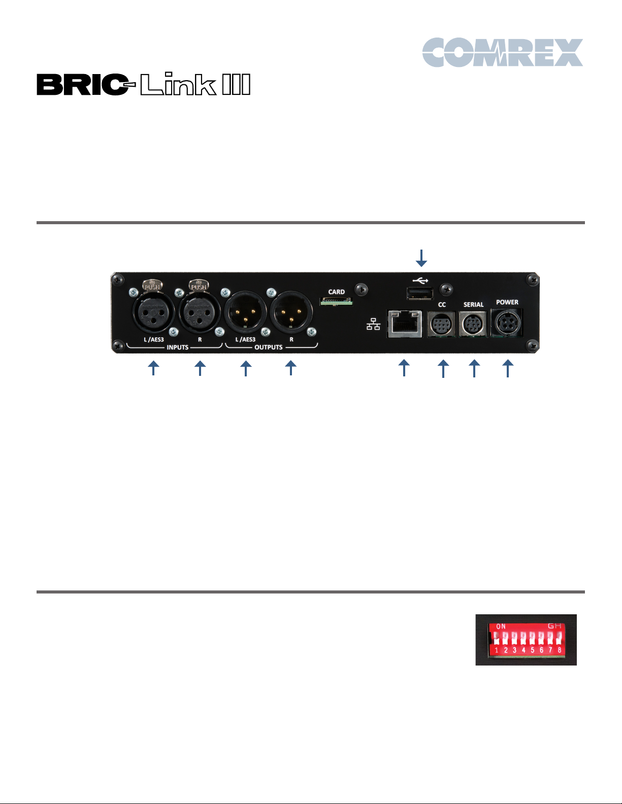
Figure 1 – Rear Panel Diagram and Descriptions
1 2 3 4 5 6
1) Left Audio/AES3 Input: Accepts professional level,
balanced analog audio, or if configured, AES3 stereo
digital audio for input.
2) Right Audio Input: Accepts professional level,
balanced analog audio.
the manual, which may be downloaded from the
BRIC-Link III product page of the Comrex website at
www.comrex.com
9
7 8
6) Contact Closures: Four sets of contact closure Inputs
and Outputs are available on this port. Inputs can be
used to send signals to the far end of the link or trigger
connections. Outputs can be used to trigger remote
control gear like automation equipment.
3) Left Audio/AES3 Output: Delivers professional level,
balanced analog audio, or if configured, AES3 stereo
digital audio for output.
4) Right Audio Output: Delivers professional level,
balanced analog audio.
5) Ethernet: 1000Base-T connection for network connections.
At a minimum, BRIC-Link III needs a source of power, an
audio connection, and a network connection.
Audio connections on the XLR jacks are wired in the
following fashion:
1 Ground
2 Balanced Audio +
3 Balanced Audio -
With a nominal input level of 0dBu (+20 dBu full scale).
You may apply AES3 digital audio to the left I/O connectors
if dip switch #1 (Input) and #2 (output) are up.
7) Serial: Connection for asynchronous ancillary data.
8) Power: 4 Pin connector for attachment of Comrex
approved DC power adapter. Requires 24V DC @ 1A.
9) USB: Attach a USB to Ethernet adapter for dual networks
via CrossLock, or Comrex Connect Modem for HotSwap.
Audio inputs should be
applied and levels checked
with dip switch #4 down. If
the audio indicators are
showing red, it indicates
the level is approaching
or reaching clipping stage.
It is OK for audio levels to
reach the yellow stage often.
The Ethernet connector is a standard 1000Base-T.
A normal patch cord, such as used for a computer,
should be connected here.
Page 2
IP Configuration - Device Manager
Initial IP configuration is handled using the Comrex
Device Manager software. This program can be
downloaded from the BRIC-Link III product page of
the Comrex website.
In order to configure BRIC-Link III, the Device Manager
must be run on a Windows PC or MAC located on the
same physical LAN as the BRIC-Link III hardware.
Once power is applied to BRIC-Link III, you have five
minutes to configure the IP settings. After five minutes,
the power must be cycled on the BRIC-Link III to make
these changes via Device Manager.
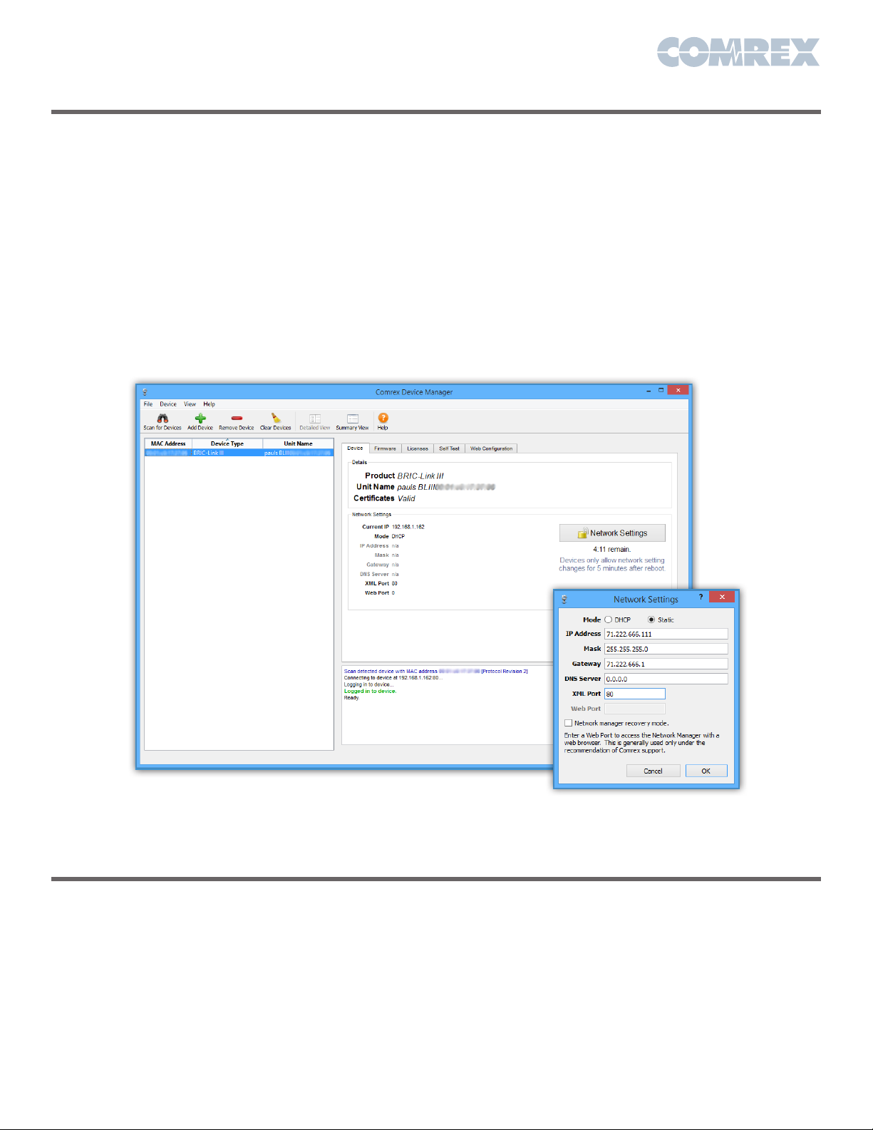
As shown below, running the Device Manager and
clicking the Scan for Devices button will produce a list
of all Comrex IP codecs found on the LAN.
Choosing the codec that appears in the left hand list,
followed by pressing the Network Settings button,
allows you to set the IP parameters of the codec.
Once you know the IP address (or have changed it using
Device Manager,) the rest of the setup and operation
of BRIC-Link III is done through the built-in Web-based
Interface (explained on the next page).
Figure 2 – Device Manager
Network Configuration
By default, the BRIC-Link III listens to IP port UDP 9000 for
incoming BRIC Normal audio connections. TCP port 80
is the default port for the Web-based Interface. These
ports may be changed through the Device Manager.
In order to accept incoming calls, your network must be
configured to forward incoming traffic over UDP 9000
to the BRIC-Link III. This can be accomplished by using
port forwarding rules, a DMZ or by putting the
Figure 3 – IP Configuration
BRIC-Link III directly on a public IP address with a
static public IP address (recommended).
If you plan on using CrossLock (described on the
last page), you will need to forward incoming traffic
over UDP 9001 to the BRIC-Link III. Comrex highly
recommends the use of CrossLock. You can learn
more by referring to the product manual, or for a quick
configuration, the last page of this Quickstart Guide.
Page 3
Controlling BRIC-Link III via the Web-based Interface
Once your IP settings are configured and BRIC-Link III
has cleanly booted on your LAN, it’s time to take a look
at the BRIC-Link III Web-based Interface. This is done
by pointing a web browser on your LAN to the IP address
of the BRIC-Link III. To do this, simply type the address
into the URL bar of an HTML5-enabled browser.
Once you are connected to BRIC-Link III, a login
screen will appear. Key in any username along with
the default password, comrex (case sensitive).*
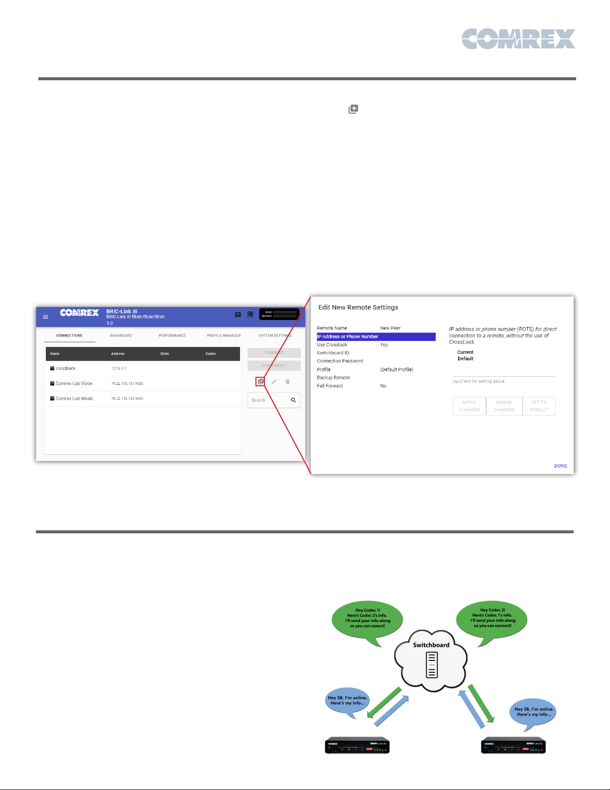
The first screen will be the Connections tab. This tab
acts like a phone book, displaying the names and
IP addresses of everyone to whom you connect. To
make an outgoing connection, you must first create
a new remote in the Connections tab. Using the
Web-based Interface, click the Add New Remote
button ( ). Enter in a remote name for the connection,
the IP Address of the unit you are calling, the audio
connection password (default is blank) and choose a
factory profile to use.
Once you are finished creating your new remote, click
OK. To start the connection, select the remote from
the list and press the Connect button. To disconnect,
simply press the Disconnect button.
*Note that it is recommended to change to a new remote
control password for security purposes. To do this, click on
the “system settings” tab and click the drop-down arrow for
“security”. Be sure to click “Apply Changes” after inputting
a new password.
Figure 4 – Connections Tab
Making Connections with Switchboard
Switchboard is a feature that allows codecs to “sync”
with a cloud-based server managed and hosted by
Comrex. Switchboard allows for easy connections to
be made between codecs without any knowledge of
IP addresses on either ends of the link. It also provides
presence and status information and can help make
some connections through routers and firewalls that
might be difficult otherwise.
Switchboard recognizes devices by their MAC
address and provides information to units in the same
Switchboard fleet that are also online. Any online units
will automatically populate in the Connections tab,
bypassing the need to know IP addresses of the units.
Switchboard is optional and will need to be purchased
through your Comrex dealer. Once you receive the
Switchboard license and apply it to your codec, contact
Comrex to set up a Switchboard account.
Figure 5 – Add New Remote
Page 4
What is CrossLock?
CrossLock describes a new reliability layer that gets
established between Comrex devices in advance of a
connection. This layer takes the form of a Virtual Private
network (VPN) between the devices.
In addition to carrying the audio media, CrossLock
allows lots of other information to be shared between the
endpoints, including information about network quality
and far-end delay settings. This provides for much better
delay management on either end of the link.
Creating a CrossLock Connection
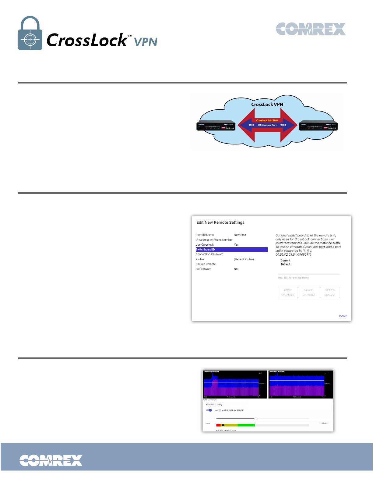
To set up a CrossLock connection, you must know the
MAC addresses of the units on both ends of the link. This
is input on the “Edit New Remote Settings” pop-up in
the Switchboard ID field. You will also need to set Use
CrossLock to “Yes”. Enter in a remote name for the
connection, the IP Address of the unit you are calling,
the audio connection password (default is blank) and
choose a factory profile to use.
In addition, the codec receiving the connection must
have a similar entry made, with the MAC Address of the
calling unit populated.
NOTE: This is important. The receiving unit must
have an outgoing connection programmed into its
address book, containing the MAC address of the
calling unit, even if that entry is never used for
outgoing calls.
Viewing CrossLock Performance
When a CrossLock connection becomes active,
the CrossLock stats are available to view on the
Performance tab. This tab is a very powerful tool to
diagnose the quality of connections as well as manage
the delay settings during the connection.
To learn more about the Performance tab, and
CrossLock stats, consult your product manual.
Put Comrex On The Line.
Figure 6 – Manual CrossLock Connection
Figure 7 – CrossLock Statistics
Toll Free in USA: 800-237-1776 • www.comrex.com
e-mail: [email protected]
19 Pine Road, Devens, MA 01434 USA
Tel: +1-978-784-1776 • Fax: +1-978-784-1717
 Loading...