

Page 1

Buddy Remote Mixer
Section
1 Introduction........................................................................................3
Description of the Buddy
2 Mixer....................................................................................................5
Description of the mixer section
3 Monitor Matrix ..................................................................................6
Description of the monitor matrix
Buddy Remote Mixer
4 Telephone........................................................................................... 7
Description of the telephone circuitry
5 Frequency Extender ..........................................................................8
Description of built-in frequency extender
6 PA System...........................................................................................9
Description of PA system feeds
7 Special Features.................................................................................10
Channel 1, Spotter and Aux-in
8 Technical Facts ..................................................................................11
Miscellaneous facts, including connecting cable pin-outs
9 Maintenance.......................................................................................13
Who to call
10 Applications.......................................................................................14
Examples
11 Special Hookups................................................................................16
How to connect a hybrid or second phone line
12 Schematics.........................................................................................17
Drawings
1
Page 2

Comrex Corporation
ABOUT COMREX
Comrex has been building reliable, high quality broadcast equipment since 1961.
Our products are used daily in every part of the world by networks, stations and
program producers.
Every product we manufacture has been car efully designed to function flawlessly,
under the harshest conditions, over many years of use. Each unit we ship has been
individually and thoroughly tested. Most items are available of f-the-shelf, either
directly from Comrex or from our stocking dealers.
Comrex stands behind its products. We promise that if you call us for technical
assistance, you will talk directly with someone who knows about the equipment and
will do everything possible to help you.
Our toll free number in North America is 800-237-1776. The toll fr ee number from
the United Kingdom is 0-800-96-2093. Product Information, Engineering Notes and
User Reports are available on the World Wide Web at http://www.comrex.com. Our
internet E-Mail address is [email protected].
WARRANTY AND DISCLAIMER
All equipment manufactured by Comrex Corporation is warranted by Comrex
against defects in material and workmanship for one year from the date of original
purchase, as verified by the return of the Warranty Registration Card. During the
warranty period, we will repair or, at our option, replace at no charge a product that
proves to be defective, provided you obtain return authorization fr om Comrex and
return the product, shipping prepaid, to Comrex Corporation, 65 Nonset Path,
Acton, MA 01720 USA. For return authorization, contact Comrex at 800-237-1776 or
978-263-1800 or fax 978-635-0401.
This Warranty does not apply if the product has been damaged by accident or
misuse or as the result of service or modification performed by anyone other than
Comrex Corporation.
With the exception of the warranties set forth above, Comr ex Corporation makes no
other warranties, expressed or implied or statutory, including but not limited to
warranties of merchantability and fitness for a particular purpose, which are hereby
expressly disclaimed. In no event shall Comrex Corporation have any liability for
indirect, consequential or punitive damages resulting from the use of this pr oduct.
COPYRIGHT NOTICE
The Comrex proprietary code and licensed, third party proprietary code residing in
and otherwise associated with this product are protected by copyright law and
international treaties. Unauthorized reproduction or distribution of this pr oduct, or
any portion of it, may result in civil and criminal sanctions, and will be prosecuted
to the fullest extent of the law.
US Government Restricted Rights - Use, duplication, or disclosure by the US Government is subject to restrictions set forth in subparagraph (c)(1)(ii) of the Rights in
Technical Data and Computer Software clause at DFARS (48 CFR) 252.227-7013 or
subparagraphs (c)(1) and (2) of the Commercial Computer Software - Restricted
Rights clause at FAR (48 CFR) 52.227-19, as applicable.
2
Page 3

Buddy Remote Mixer
SECTION 1. BUDDY
The Comrex Buddy is a multifunction remote console designed to handle the
complexities of ISDN remotes. It is also an ideal stand-alone console for sending
program over standard dial lines. The Buddy is a complete remote studio, providing audio mixes for program feeds, communications, headphones and public
address systems.
While digital audio codecs are revolutionizing the way broadcasters do remotes,
multiple pieces of audio gear with complex cabling are often required in order to
achieve the custom audio feeds at a remote site. Typical requirements include:
¤ Main program audio channel sent to station
¤ Headphone audio for program host and guests
¤ Intercom audio for producer or engineer
¤ Special mix for PA system
¤ Audio for emergency backup system
These individual mixes often contain one or more of the following sources:
¤ Main program audio
¤ Return codec channel
¤ Phone line intercom channel
¤ Producer or spotter mike
With all of these different mixes and with each mix requiring different levels, the
remote site often resembles a wiring nest. The Buddy performs all these functions
in one small rugged box.
The Buddy is a full featured 4 channel microphone/line mixer plus a headphone
monitor control matrix. Included is a single line frequency extender (encoder), a
telephone coupler with dial pad and a separate PA mixer.
Operation of the Buddy is very straightforward. The four channel mixer permits
you to mix four microphones or two microphones and two line level sources (tape,
CD, locker room feeds, referees calls from the field or even another Buddy). Plug
in whatever source you have, put the level switches in the position that match
their levels and you are ready to go. The mix is available on the rear panel through
a 3-pin XLR connector marked PROGRAM OUTPUT. The following sections will go into
more depth on each area of the Buddy and then we will show you some application examples.
3
Page 4

Comrex Corporation
Specifications
Connections Levels
Program in: Microphone input,
(4) 3-pin XLR female including Spotter:
Headphone out: -70 to -30 dBu balanced
(4) 1/4" phone jack Line input,
Aux-in: including Aux-in and Spotter:
3-pin XLR female -4 to +8 dBu balanced
Spotter mic/line: (Channels 3, 4 & Spotter
3-pin XLR female switchable between mic & line)
PA feed out: PA feed out:
3-pin XLR male 0 dBu balanced, nominal level
Program out: Program out:
3-pin XLR male externally switchable between
Telephone line: 0 dBu and +4 dBu balanced
RJ-11C 6 pin modular jack
Output Clipping Level AF Response
+24 dBu +/-0.5 dBu, 50 Hz to 15 kHz
Distortion Power
Less than 0.1%, 50 Hz to 15 kHz 120 VAC/60 Hz or
240 VAC / 50 Hz
(externally switchable)
Drain: 10 watts max
Size Weight
11.25"W x 11.5"D x 4.5" H 8 lbs; 3.6 Kg
4
Page 5
Buddy Remote Mixer
SECTION 2: MIXER
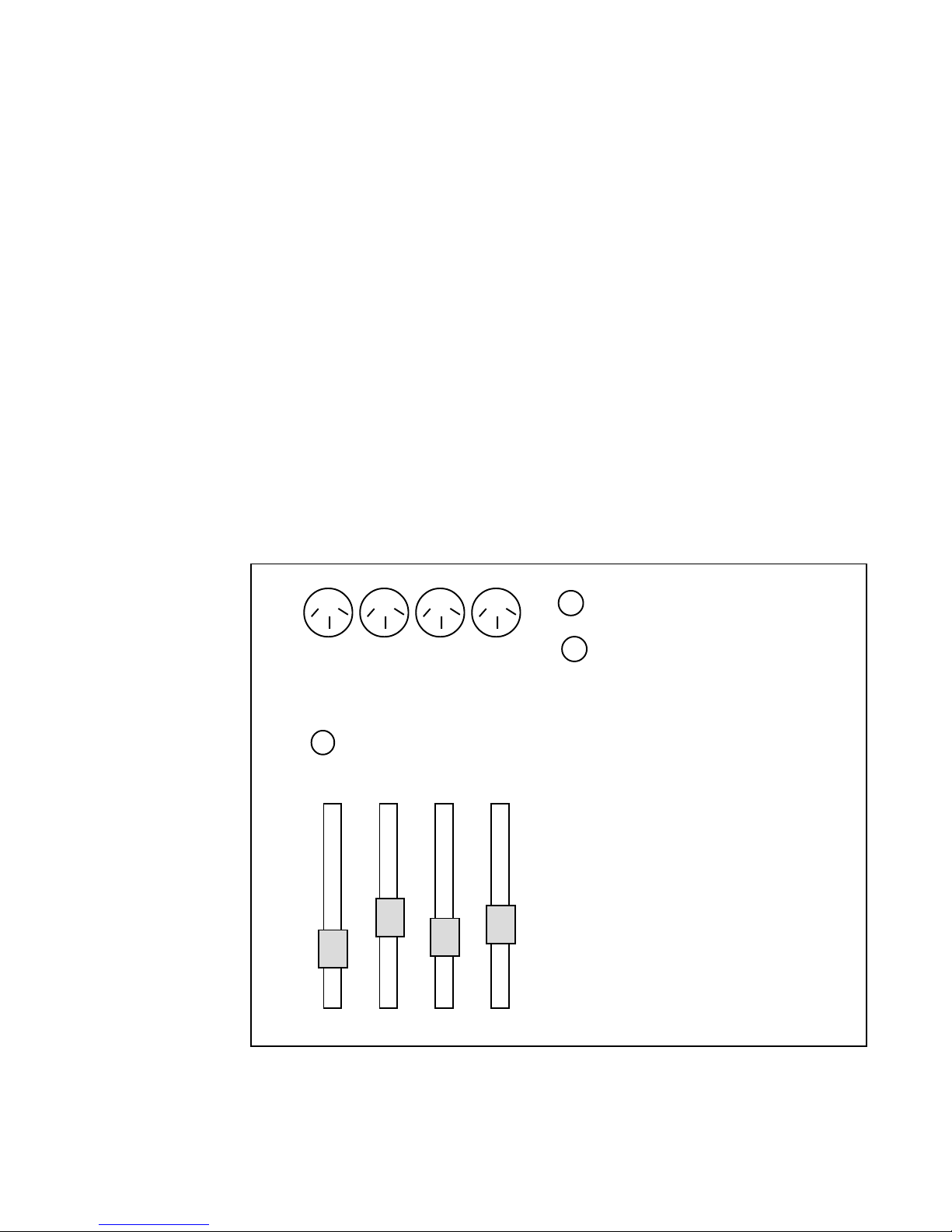
Connectors Four 3-pin XLR female Located on front panel, top left
Ch 1,2 - microphone only
Ch 3,4 - microphone/line
Operation
Fig 1
Microphone
Controls
The
MICROPHONE connections are located on the top of the front panel. Each channel
has a separate slide fader for controlling levels. The faders in the Buddy are manufactured by Penny & Giles and are the same as those used in the very best broadcast and recording consoles. The four channels are summed together and fed to
the program output and to an LED volume unit indicator as well as the monitor
matrix, the frequency extender (encoder) and the PA feed section.
There is no audio on a channel when the fader is in the bottom position.
1234
microphone inputs (ch 3&4 mic/line)
mic/line
ch 4 ch 3
telephone talkback
(mic 1 only)
1234
5
Page 6
Comrex Corporation
SECTION 3: MONITOR MATRIX
Connectors
Operation
Four 1/4" phone jacks Located on front panel, top left
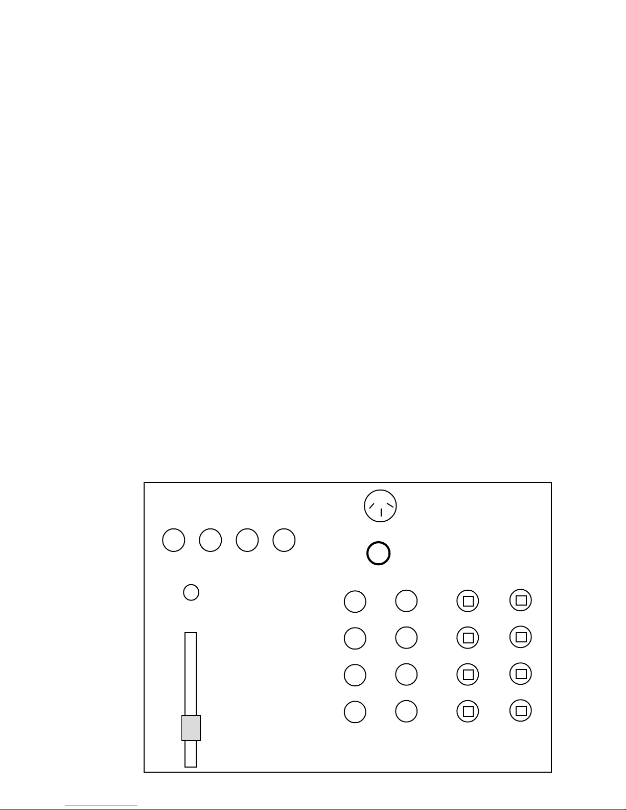
The monitor section controls what each headphone receives. There are four rows of
color coded knobs in two columns located to the right of center on the front panel.
The color coding corresponds to the slide faders. Each headphone is color coordinated with its corresponding microphone channel. Channel 1 has red slide faders
and red headphone level knobs. Channel 2 is yellow, 3 is green and 4 is blue.
The left side of the headphone hears program audio and the right side hears audio
selected through the headphone cue selection push-buttons. The left headphone
knob controls the level for the left side of the headphone. The right knob controls the
audio level for the right side. The HEADPHONE CUE SELECTORS are push-button switches
located to the right of the headphone level knobs. These switches are of the locking
type which means that when they are pushed down, they latch in the down position.
When they are down and engaged, the push-button window will be red. They
control the audio sources fed into the headphones. The left column of push-buttons
selects what channel 1 will hear in the right headphone. The right column of
switches similarly controls channels 2,3,&4.
The cue selections are
PROGRAM, TELEPHONE, SPOTTER AND AUX-IN.
Fig 2
Headphone
Controls
NOTE: When SPOTTER is selected for channels 2,3,&4 AND the TELEPHONE TALKBACK is
engaged on channel 1, any audio on channel 1 will be heard by channels 2,3,& 4. If
there is audio on the SPOTTER input, the two audio sources will be mixed together.
For more information, see Section 7.
spotter
headphone outputs
1 2 3 4
telephone talkback
(mic 1 only)
1
2
3
4
prog.
tel.
spotter
aux-in
6
left (program) right (cue) ch 1 ch 2,3,& 4
Headphone levels Headphone cue selections
Page 7

SECTION 4: TELEPHONE
Buddy Remote Mixer
Connector
Operation
RJ11-C modular plug Located on back panel
The telephone circuitry in the Buddy contains a dialer which may be place in the
either the tone or pulse mode by means of the
PULSE/TONE toggle switch located on
top right of the front panel. The circuitry also contains an adjustable HYBRID and
receive level control.
If the telephone line is dialed into the Buddy, a red LED marked ring will light up
when the line is ringing. The LINE SEIZE push-button will enable the line to be picked
up or released. The telephone is “off hook” when the red window is showing on
the push-button. The phone is “on hook” when the window is black.
The level fed into the telephone line is quite a bit higher than the receive level.
Also, the receive level on telephone lines will vary from call to call. The Buddy
contains an automatically balancing hybrid which is designed to reduce the level
of your local audio so that you can better hear the incoming audio. To control the
incoming level of the telephone line in your headset, first adjust the “telephone
receive level” knob as high as required without distorting the sound in your
headphones. You can then adjust the right headphone knob as needed. The two
controls should be able to handle the wide variety of levels found on telephone
circuits.
Cellular
Telephone
This will require an RJ11 (standard modular telephone jack) access to the cellular
telephone. Many current model cellular telephones have this RJ11 access either
built-in or available optionally for interfacing portable FAX machines or computer
modems. The Buddy's RJ11 jack can be connected into this cellular RJ11 accessory
port with a simple modular telephone cord.
Fig 3
Telephone controls
Upper right - front panel
telephone
receive level
ring
line seize
off hook
on hook
7
Page 8

Comrex Corporation
SECTION 5: FREQUENCY EXTENDER
A one line frequency extender encoder is included in the Buddy. This frequency
extender can be used to significantly improve the quality of program sent over a
standard dial-up telephone line or cellular telephone (see Telephone, page 7.) A
one line frequency extender decoder is required at the receiving end. The current
model is an LXT/R, however the Buddy's frequency extender encoder is also
compatible with all older one line frequency extender decoders.
Operation
How it Works
To use the frequency extender, seize the telephone line by engaging the “on hook
/off hook” push-button. When you hear the dial tone (make sure your headphone cue is selected to telephone) dial the receiving station. Once someone
answers, you may talk to the other end. Make sure your microphone fader is up
and the
FREQUENCY EXTENDER push-button is in “bypass” position (the window will
be dark.) When you are ready to send program, engage the frequency extender
by pushing the button down so the red window shows. NOTE: When the frequency extender is engaged, the return audio on the telephone line is cut from the
headphones. During program breaks, you can switch to “bypass” in order to
communicate with the station through the headphones and microphones. (See
page 10 for instructions on connecting a second telephone line into the Code
Buddy for full time cueback.)
NOTE: When using the frequency extender, program audio will be heard in
headsets when the cue selection is telephone.
Dial telephone lines sound “tinny” because they only pass 300 - 3100 Hz. However, the human voice carries most of its resonance and “natural” sound between
100 and 800 Hz. When you speak on the phone, you have no trouble understanding a conversation, but the sound is tinny, and listening to phone transmissions
over a long period of time produces ear fatigue.
The telephone company selected the 300-3100 Hz range for economic reasons ( a
smaller bandwidth allows them to transmit more calls per line) and so the power
lines sharing the same poles along the street do not infiltrate the phone line and
induce a “hum” in telephone transmissions. One line systems encode program
audio by shifting all frequencies up by 250 Hz, so that 50 Hz becomes 300 Hz
allowing it to pass through the filters on the telephone line. At the decode end, all
frequencies are downshifted 250 Hz, restoring 2-1/2 octaves of program energy
at the low end (see figure 4).
Fig 4 One Line Frequency Extender
LXT/R Encoder LXT/R Decoder
Upshift Modulator
+250 Hz
8
Telephone Line
A dial telephone line
passes 300 to 3100 Hz
Downshift Modulator
-250 Hz
Program
Output
50 Hz to
2850 Hz
Page 9

SECTION 6: PA SYSTEM FEED
Buddy Remote Mixer
Connector
Operation
PA feed out 3-pin XLR male Located on rear panel
If a remote broadcast or a remote talkshow is being conducted with an audience watching, some means of making it possible for them to hear may be
desired. The PA feed section of the Buddy is a two input mixer with gain
control for each input.
One input is the program being sent to the station or network and the other
comes from the aux-in. Details on the
AUX-IN connection are on page 8. Aux-
in can be fed from the station, a local tape deck, or any other line input. If a
digital codec is being used to send a remote talk show to the station and
callers are being taken in at the station, the resulting mix-minus comes back
over the return channel into the aux-in of the Buddy and the talk show host
can hear the callers. Putting the host and callers out over the PA system is
not a simple summing of the parts. The acoustics of the remote site will
control how loud the host can be before feedback howl will occur. If simple
summing is used the level of the callers might be too low. The separate
controls for each will permit much better balance.
Fig 5
PA Feed
Rear Panel
p.a. mix
level adjust
programaux-in
p.a. feed
9
Page 10

Comrex Corporation
SECTION 7: SPECIAL FEATURES
Channel 1
Spotter
Channel 1 is ideally suited for use by a producer. It has separate cue selection
capabilities and can be cut from the air to use the telephone.
Channel 1 has the capability to make cue selections independent of channels 2, 3
& 4. Channel 1 can be listening to the spotter, while the others listen to the
program or channel 1 can listen to the telephone while the others listen to the
aux-in.
When the
TELEPHONE TALKBACK switch is pushed in, channel 1 microphone is taken
from the program mix and placed on the telephone. The fader on channel 1 must
be up. To listen to incoming telephone audio, the telephone cue must be selected
for channel 1.
A producer on Channel 1 can also be heard in the headphones of channels 2,3,& 4
without his audio appearing on the program output. T o do this, the channel 1
TALKBACK push-button must be engaged and the fader up. Channels 2,3,& 4 must
select SPOTTER as a cue selection. For this mode, channel 1 audio (the producer) is
summed with spotter audio
The Spotter input is through an XLR female connector and is switch selectable
between microphone and line input levels. The SPOTTER audio appears only as a
cue selection heard in the right headphone. Spotter input can be from a person
on the field at a sports event identifying players, or from any information source
that you do not want to go out over the air. There is a separate level control for
spotter input.
Aux-in
Aux-in is through an XLR female connector. This input is line level and can be
heard in the headphones or through the PA system. Aux-in can be a tape, CD,
another Buddy, program return from the audio codec (if an ISDN line is being
used) or any other line input. The level control is located on the top right of the
front panel.
If you plan to use the Frequency Extender and telephone line built into the Buddy
for program transmission, you may want to interface a second phone line for full
time cueback from the station. To do this, you will need an external telephone
coupler (Comrex Model TCB-1 Manual Telephone Coupler or Comrex Model
TCB-2 Auto-Answer Telephone Coupler) to connect the second telephone line
into the Buddy. This coupler can be connected into either the SPOTTER or AUX-IN
connections. By making the appropriate cue selection (either SPOTTER or AUX-IN),
you will be able to hear the cueback line in your left ear. Note: Receive levels of
phone lines can vary significantly. If the receive level is very low, we recommend
using the SPOTTER connections set to MIC level. Level adjustments can be made with
the volume controls on the spotter or aux-in positions and with the volume
controls for the left headphones.
10
Page 11

SECTION 8: TECHNICAL FACTS
Buddy Remote Mixer
Levels
Power
Pin-outs
The program output level may be set to either 0 dBu or +4 dBu by means of a
toggle switch on the rear panel.
The power can be set to eight 115 volts AC or 230 volts AC through a switch
on the rear panel of the Buddy.
Reference Connector Pin # Pin Names Connector
Description Type or Term Names
J7 3 Conductor Tip Cue 1 - Right Headphone 1
1/4" Phone Jack Ring Pgm 1 - Left Output
Sleeve Gnd
J9 3 Conductor Tip Cue 2 - Right Headphone 2
1/4" Phone Jack Ring Pgm 2 - Left Output
Sleeve Gnd
J8 3 Conductor Tip Cue 3 - Right Headphone 3
1/4" Phone Jack Ring Pgm 3 - Left Output
Sleeve Gnd
J10 3 Conductor Tip Cue 4 - Right Headphone 4
1/4" Phone Jack Ring Pgm 4 - Left Output
Sleeve Gnd
J4 Female 1 Gnd Microphone 1
XLR 2 In + Input
3 In -
J5 Female 1 Gnd Microphone 2
XLR 2 In + Input
3 In -
J1 Female 1 Gnd Microphone /
XLR 2 In + Line 3 Input
3 In -
J2 Female 1 Gnd Microphone /
XLR 2 In + Line 4 Input
3 In -
11
Page 12

Comrex Corporation
Reference Connector Pin # Pin Names Connector
Description Type or Term Names
J3 Female 1 Gnd Spotter
XLR 2 In + Input
3 In -
J6 Female 1 Gnd Aux-In
XLR 2 In + Input
3 In -
J13 RJ-11 Pin 3 Ring Telephone
Pin 4 Tip Line
J2 Male Pin 1 Gnd PA Feed
XLR Pin 2 Out + Output
Pin 3 Out -
J3 Male Pin 1 Gnd Program
XLR Pin 2 Out + Output
Pin 3 Out -
The Buddy audio inputs and outputs are designed to accept and to drive electrically balanced input and output signals. Sometimes, it is unavoidable to use
unbalanced audio signals, like those found on consumer audio equipment. In the
case of an unbalanced signal being fed into the Buddy via the XLR connectors,
always connect the “audio high” signal to pin 2, and connect the audio ground
to pins 1 and 3. Likewise, when feeding unbalanced equipment inputs from the
Buddy, connect pin 2 to the “audio high” input pin, and connect pins 1 and 3 to
the audio ground input.
12
Page 13

Buddy Remote Mixer
SECTION 9: MAINTENANCE
The Comrex Buddy is manufactured very carefully and with the highest quality
parts. It has been designed with the rough life of remotes in mind and should
give you many years of trouble free service. We at Comrex stand behind this
products as we do with all our products.
If you do have any problem with the Buddy, please call us first. We can listen to
your feed and often diagnose problems and offer suggestions that will correct
the problem. In our experience, the most common problem experienced with
audio equipment are with cables. We suggest that you consider purchasing
“ready-made” cables.
Another very strong suggestion is that you do not permit any modification of the
Buddy. Comrex policy requires that any equipment returned to us for repair
must be “de-modified” before it can be examined. This raises the cost of the
repair and, in many cases, is the cause of the problem. If you feel that a special
feature must be added, please talk with us first to insure it is done correctly.
13
Page 14
Comrex Corporation
SECTION 10: APPLICATION EXAMPLES
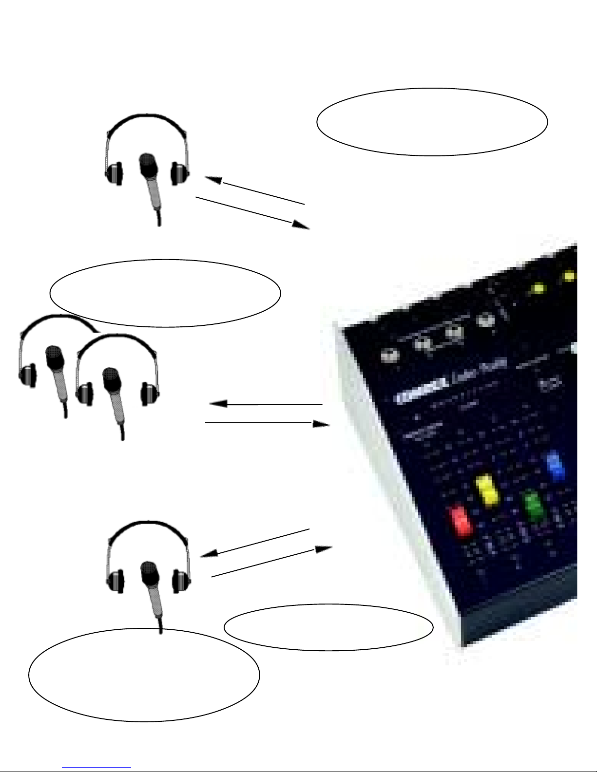
Program Host
Local Program
Callers
Host microphone on
Channel 2
Channels 3 and 4 are switchable
between microphone and line levels
so these sources could be a tape
deck, etc.
The spotter mic can be selected
into each of the headsets. This
input is switchable between mic/
line, so a stadium PA could be fed
into here.
& Producer
Guest
Guest
Producer
Local Program,
Callers & Producer
Guest Microphones on
Channels 3 & 4
Callers
feed
Local
Program,
telephone
Return
to station
Talkback
line
phone
&
over
Channel 1 is cut from air for
phone line intercom by pushing
in the talkback button. In the
intercom mode, any headphones
which have selected “spotter”
will also hear channel 1 “inter-
com” audio.
14
Headphone 1 has a cue mix which is
separate from headphones 2,3 & 4.
Page 15
Spotter Mic
Buddy Remote Mixer
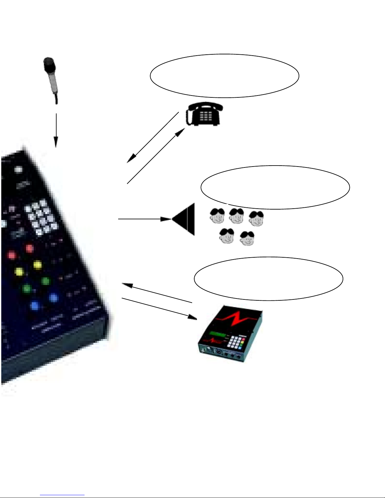
A single line frequency extender
is included to improve audio
quality when the phone line is
used for program transmission.
Phone Line for Intercom
or Program Backup
Talkback to station
This is a separate mix of local
program and codec return audio
with level controls for each ele-
ment.
PA
Feed
Caller Audio from Station
The return audio on the codec can be
connected to the auxiliary input and
heard in the headphones.
Local Program
Audio
Digital Audio Codec
Remote broadcast showing some of the capabilities of the Comrex Buddy.
In this setup, a post-game talk show is being sent on ISDN. There is a host and two guests
at the remote site, along with a producer. The Buddy is connected to a Digital Audio Codec
(in this instance the Comrex Nexus) for 15 kHz mono program feed and return audio. Callers are fed down the return ISDN channel from the station into the mixer's auxiliary input and
are heard in both the headphones and the PA output. A producer is using channel one in the
intercom mode which cuts that channel from air and allows him to communicate with the
station over the phone line in the mixer. The producer is also being heard by the host and his
guests. The PA feed is a mix of local program and the caller audio from the station.
15
Page 16
Comrex Corporation
SECTION 11: SPECIAL HOOKUPS
Connecting a
Hybrid to the
Buddy
We have been asked by some Buddy users if there is a way to incorporate telephone interviews through the Buddy. We explain that the Buddy’s telephone
interface is meant for communications or for program delivery and not to
interface caller audio with host audio for interviews. Combining the host’s
audio with a caller ’s voice requires a telephone hybrid and also requires that a
mix-minus feed be available to send back to the caller.
The diagram below shows how to connect an external telephone hybrid to the
Buddy to create the necessary mix-minus. In this application, the PA output
becomes the main program feed, combining the host and caller audio and the
Program Output is used to provide the mix-minus back to the caller.
Note: If you are using the Buddy to feed an ISDN or SW56 codec, you can connect
the codec return audio into SPOTTER (rather than the AUX-IN) to bring the return
audio into the headsets.
Host Audio to Caller
- “Mix-minus”
The PA Out becomes the main
program feed, combining the
Program (host) and Aux in (caller.)
Telephone
Hybrid
Program
Out
PA
Out
Buddy Back Panel
Connecting a
Second Phone
Line into the
Buddy.
Caller Audio to Program
and Host Headphone/s
Host Mic/s
Aux In
Buddy Front Panel
If you are using the telephone interface built into the Buddy for frequency extended program transmission, you may wish to have a second “cueback” line for
fulltime communications with the studio. This can be done by connecting a
second phone line into an external telephone coupler (i.e. Comrex Model TCB-1)
and feeding this coupler into the SPOTTER position, which can be selected into
the headsets. Depending on the receive level of the telephone line (they can vary
anywhere between -40 and -15 dBm), you may select either mic or line level and
then adjust the SPOTTER and headphone volume controls to a comfortable level.
16
Page 17

SECTION 12: SCHEMATICS
Buddy Remote Mixer
17
 Loading...