

Page 1
Quickstart Guide
ACCESS 2USB Portable Diagrams and Descriptions
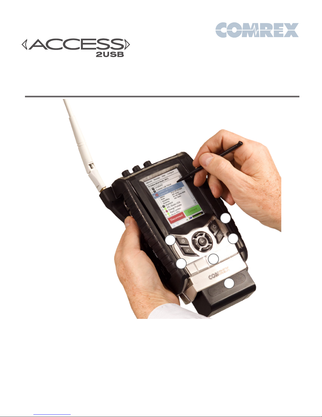
Figure 1 – Front Panel Diagram
3
1) Backlight Key - Controls operation of the display
light. Hold for one second to enable Power Saving
Mode, where LCD lighting will turn off after ten
seconds of non-use. Press the key to turn on light for
another ten seconds. Hold for one second to enter
Toggle Mode, where presses will turn light on/off.
Hold for one second to return to default Always On
Mode.
2) Directional Cursors & Enter Key - May be used
instead of touch-screen to navigate and select
options in the User Interface.
1
5
2
4
6
3) Power Key - Hold this button down for one
second to turn the ACCESS 2USB on or off.
4) F1 Key - Used to access the top menu bar.
5) F2 Key - This is user programmable; refer to the
User Interface section in the product manual for
details.
6) Battery - Clip on Lithium-Ion battery pack.
Page 2
M
ONO IN
M
IC
L
INE
M
ONO IN
L
OCAL
R
ETURN
O
UTPUT
S
TEREO
L
INE IN
L
INE
O
UT
M
OBILE
IN/O
UT
O
UT
1 2
3 4 5
6 7 8 9
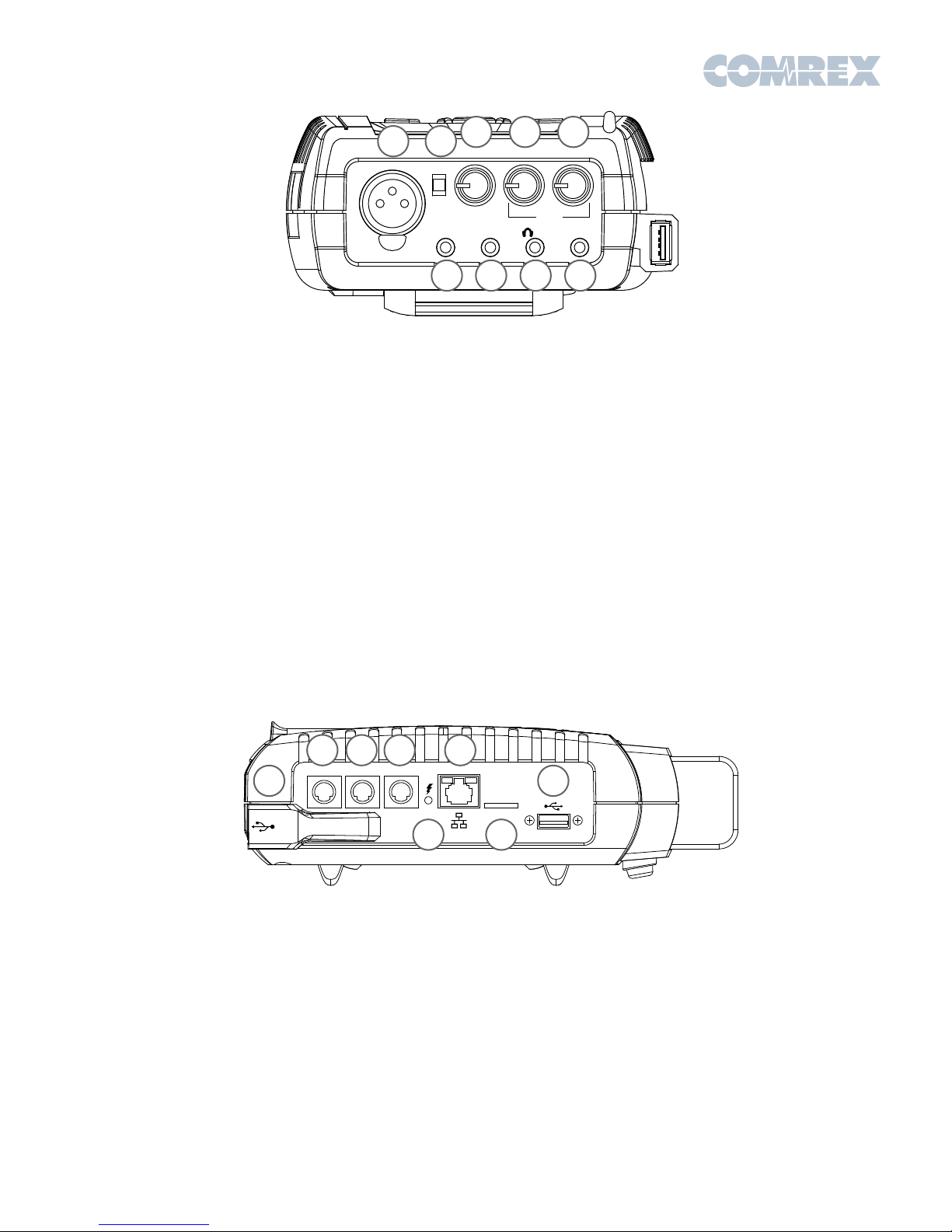
Figure 2 – Top Panel Diagram
1) Mono In - 3-pin female XLR connector designed to
accept a balanced, microphone or line level audio
feed. The input level is adjustable via the Mono In
control. +12V of phantom power may be applied to
this input through the Audio Controls menu.
2) Mic/Line Switch - Determines whether the Mono
In jack is configured to receive a microphone level
(-70 to -40 dBu) or line level (-10 to +4 dBu) audio
input.
3) Mono In Level Control - Adjusts the level of
Mono In audio. These knobs may be extended or
retracted by pressing them in.
4) Local Output - Adjusts the level of locally
produced audio at the headphone jack.
5) Return Output - Adjusts the level of decoded
return audio at the headphone jack.
1 2 3 5
SERIAL CONTACT
POWER
7
CLOSURES
4
6) Stereo Line In - 3-conductor 1/8” (3.5mm)
connector for attachment of unbalanced stereo input
devices.
7) Stereo Line Out - 3-conductor 1/8” (3.5mm)
connector for delivery of fixed level, unbalanced
output audio (selectable in software between Local,
Return, or Both).
8) Headphone Out - 3-conductor 1/8” (3.5mm)
connector for attachment of stereo headphones
with the capability of driving low-impedance
headphones.
9) Mobile In/Out - 3-conductor 1/8” (3.5mm)
connector for attachment of a hands-free cellular
port. Program audio is sent to this port, and receive
audio may be routed to the Headphone/Line
outputs.
7
6
Figure 3 – Side Panel Diagram
1) Power Connector - 5-pin mini-DIN jack for
connection of included AC power adapter. Adapter
works from 100-240VAC. Be sure to use only Comrex
supplied power adapter.
2) Serial Jack - 8-pin mini-DIN jack for connection of
a serial cable to facilitate ancillary data transfer.
3) Contact Closures - 9-pin mini-DIN jack is used
for connection to four contact closure inputs and
outputs.
4) Charge Indicators - Indicated the battery
charging state: Red = Charging, Green = Fully
Charged.
5) Ethernet Port - 10/100Base-T Ethernet jack for
connection to wired IP networks.
6) Micro SD Card Slot - For future use. Unsupported
at this time.
7) USB Ports - These ports support the included USB
Wi-Fi adapter, POTS modem and approved thirdparty USB 3G/ 4G devices.
Page 3
Setting up the Hardware
At a minimum, ACCESS needs a source of power,
an audio connection and a network or POTS
connection.
The ACCESS 2USB comes equipped with two power
sources: A small external power supply delivers
15VDC from worldwide AC mains, and a Li-Ion
battery pack delivers backup or main power for up
to six hours.
The Mono In and Headphone Out levels are user
Network Device Configuration
The Ethernet port on ACCESS 2USB is enabled and
set to DHCP by default.
In order to make a connection on a different
network, an Ethernet or USB network device (Wi-Fi,
4G or POTS) must be installed and enabled on the
ACCESS 2USB. USB devices can be safely installed
or removed when the ACCESS is powered on. IP
network devices must have a valid IP address
before a call can be made.
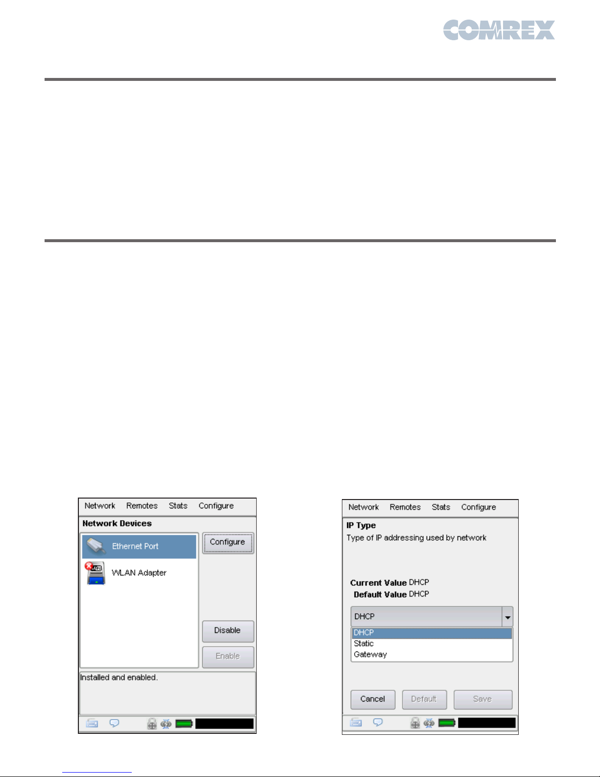
To enable your network device, go to Network >
Manage Networks on the ACCESS. This list displays
all devices that have been used with the ACCESS.
When you install a compatible device in the ACCESS
by plugging it into one of the USB slots, it will appear
in this list.
To enable the network device, click the desired entry
in the list, and click the Enable button on the righthand side. The status message near the bottom
adjustable. The Stereo Line In connector has a
nominal level of –10dBu for connection to consumer
level output devices. The Line Out connector has a
nominal level of -10dBu as well.
The Ethernet connector is a standard 10/100Base-T.
A normal Cat5 cable, such as used for a computer,
should be connected here.
The USB POTS modem should be used with a
dedicated analog telephone line.
of the screen should change to “Installed and
Enabled”.
As shipped from the factory, ACCESS configures
new network devices for DHCP, which means it will
automatically attempt to obtain an IP address from
your network. When the ACCESS obtains a valid IP
address, the status will show “Current address“,
with the current IP address. If you wish to configure
the device for a static address, select it in the list
and click the Configure button.
On the Locations tab, press Add to create a new
location, select Name and press Edit. Change the
name to something specific and press Save after
each setting change. Select IP Type and press
Edit to change the mode to Static. You will then be
able to edit the IP address, netmask, gateway and
DNS. On the Settings tab, edit the Active Network
Location so it points towards the new location. Press
Apply when done.
Figure 4 - Manage Networks
Figure 5 - TCP/IP Configuration
Page 4
Making a Connection
To make an outgoing connection, you must first
create a new remote.
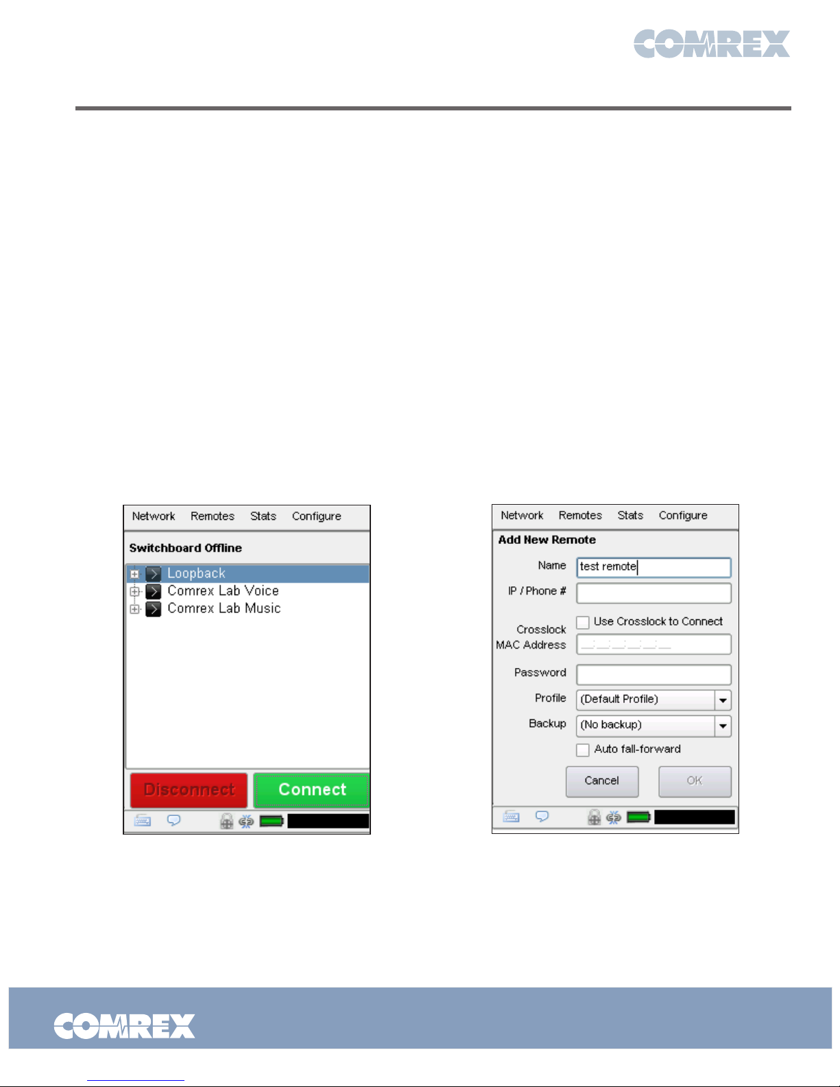
To do so, click Remotes > Add New Remote.
Enter in a remote name for the connection, the IP
Address or phone number of the unit you are calling,
the audio connection password (if any is set) and
choose a profile to use.
To bring up the on-screen keyboard, click the
keyboard icon in the bottom left-hand corner of the
screen. Click it again to remove it.
There are several factory profiles available to use for
your remote. The following are the most commonly
used:
Opus Mono - This is the default choice of profiles
for new remotes. It provides low delay, full duplex,
20KHz mono audio channel over a low (48Kb/s) data
stream.
3G AAC-ELD - This mode is optimized for use over
3G/4G wireless networks like UMTS or LTE. Because
cell networks are asymmetrical (they have higher
download speeds), this profile delivers a robust,
low delay mono stream in the upload direction, and
a low delay, stereo stream in the reverse direction.
This stream can be useful to send separate program
and cueing channels, as an example.
POTS – This profile must be used when dialing a
connection to another codec over POTS
Once you are finished creating your new remote,
click OK. To start the connection, select the remote
from the list and press the Connect button. To
disconnect, simply press the Disconnect button.
Figure 6 - Manage Remotes Figure 7 - Add New Remote
Put Comrex On The Line.
Toll Free in USA: 800-237-1776 • www.comrex.com
e-mail: [email protected]
19 Pine Road, Devens, MA 01434 USA
Tel: +1-978-784-1776 • Fax: +1-978-784-1717
 Loading...