

Page 1
Temperature Monitoring
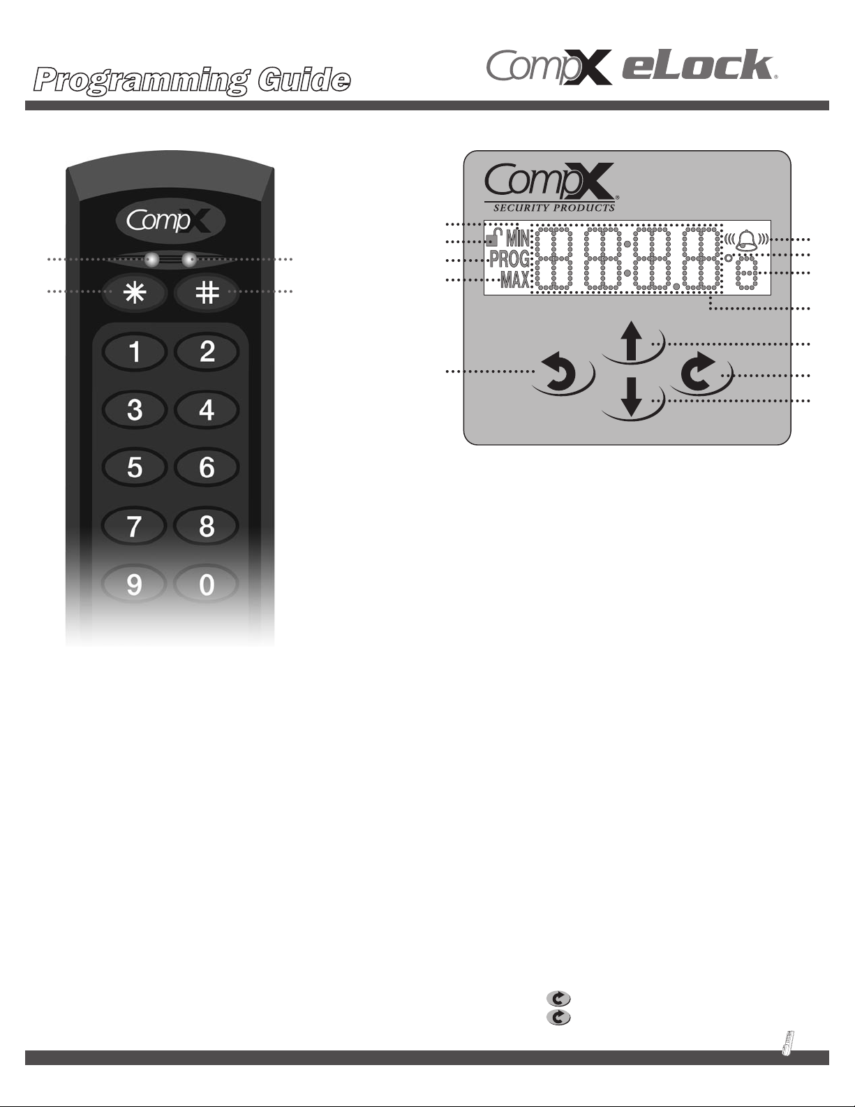
CompX eLock® unit CompX eLock® temperature display keypad
A
C D
B
A
B
C
A
D
E
E
F
H
CompX eLock® unit
A: Green LED indicator of successful open cycle
B: Red LED indictor of unsuccessful attempt
C: Asterisk button used to clear entry or remove user /
supervisors
D: Pound button used to insert PIN or program new users /
supervisors
G
Note: not actual size; shown at 150%
I
J
CompX eLock® temperature
display keypad
A: Minimum and maximum temperature limits
B: Unit is unlatched. This icon is not visible when latching
mechanism is in the locked position.
C: Programming mode
D: Bell icon indicates alarm is enabled. Flashing bell sound waves
means the alarm is sounding. Flashing bell means the alarm
has been muted. Does not indicate alarm volume setting:
soft-medium-loud.
E: Degree sign and unit of temperature measure. Will either show
˚C or ˚F.
F: Display of time or temperature or setting.
G: Back button
H: Scroll up button
I: Enter button
J: Scroll down button
***IMPORTANT INFORMATION***
This unit comes with factory reset codes/cards. Please save the attached stickers/cards and place in a secure location. This unit can
be reset to original Factory Set-up Mode by entering the factory reset code or presenting the factory reset card. CAUTION: ENTERING
THE FACTORY RESET MODE WILL ERASE ALL USERS/SUPERVISORS THAT ARE CURRENTLY PROGRAMMED IN THE LOCK.
Basic unit Features:
k Records 8,000 temperature events
k Accuracy within +/- 1˚C
k Single probe, mounted in non-toxic glycol bottle
k Easy to read LCD display
k Operating range of from -40˚F to 122˚F (-40˚C to 50˚C)
k Requires 6 AA batteries (9V) not included
General functionality:
k Pressing the scroll up arrow will display the maximum
temperature that the monitor has recorded
k Pressing the scroll down arrow will display the minimum
temperature that the monitor has recorded
k Pressing the key will display the current date
k Pressing the key twice will display the day of the week
1
Page 2
Temperature Monitoring
Getting Started
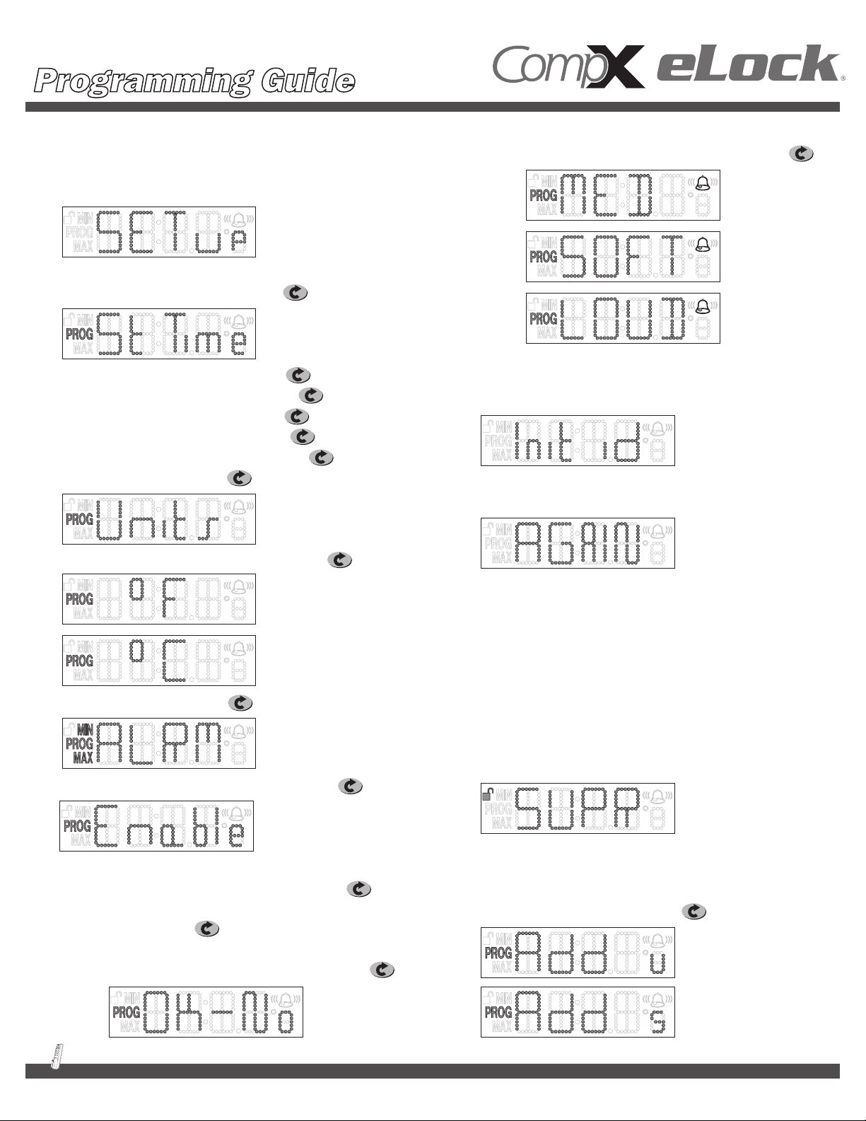
1. Unit is shipped in “Set-up” mode. Once 6AA batteries
(not included) are installed, the LCD will say “SET up."
2. Press and hold # (about three seconds) to get started.
3. LCD will display ST Time (set time). Hit .
4. Set Year using up and down arrows. Hit .
5. Set Month using up and down arrows. Hit .
6. Set Day using up and down arrows. Hit .
7. Set Hour using up and down arrows. Hit .
8. Set Minutes using up and down arrows. Hit .
9. Display will show “Units." Hit .
d. Adjust speaker volume, 3 possible settings, LOUD,
MED, SOFT, by using up and down keys and hit .
13. The unit will display “Init ID” which is prompting you to program
the initial credential. Remember, the first credential is always
a Supervisor and goes into Slot 001.
14. Enter PIN or present card followed by #.
15. Unit will display “AGAIN” for confirmation of the code / card.
10. Choose ˚F or ˚C with up and down arrows. Hit .
11. Display will show “ALRM." Hit .
12. Enable or disable alarm with up or down key. Hit .
a. If enabled, minimum degrees will appear.
Adjust using up and down arrows and hit .
b. Adjust Maximum degrees using up and down
arrows and hit .
c. If you want to disable the alarm, press the up or down
arrow until it says “Enable – Okay No” and hit .
16. Enter PIN or present card followed by # again.
17. The unit is now successfully initialized. The LCD display will
alternate time and temp.
How to Change Modes
After Initial Set-up
ADDING USERS OR ADDITIONAL SUPERVISORS:
1. Enter supervisor code/card and press #. Display will show “Supr.”
2. Press and hold # (again) for about three seconds.
3. Display will show “Add u” which means add user. If you use
the up or down arrow, the display will show “Add s” which
means add supervisor.
4. Pick either “Add u” or “Add s” and hit .
2
Page 3
Temperature Monitoring
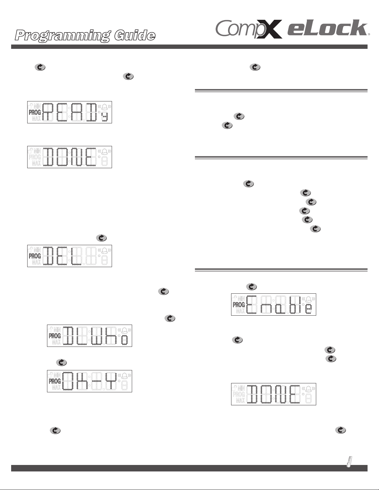
5. The display will show the next available slot to program into.
Hit (All entries done by slots will need to be logged.)
Take the next available slot by pushing or program
by specific slot by scrolling with the up and down buttons.
6. The unit will display “READy."
7. Enter PIN followed by # or present card.
8. Unit will say “DONE.”
9. Unit will return to normal operating mode, showing alternating
time and temp.
DELETING USERS OR SUPERVISORS:
1. Enter supervisor code / card and press #. Display will
show “Supr.”
2. Press and hold * for about three seconds.
3. Display will show “DEL." Hit .
“ALRM” – use the up or down arrows to toggle between Units, St Time
and ALRM modes. Hit on desired mode.
UNITS
If Units is chosen, the eLock will allow you to select either F˚ or
C.˚ Scroll using the up or down arrows until “Units” appears on the
display and hit . Using the up or down key, select either F˚ or C˚
and press . The display will show “DONE” momentarily and then
revert back to time and temperature.
SET TIME (ST TIME)
If St Time is chosen, the eLock will allow you to adjust the time and
date. Scroll using the up or down arrows until “St Time” appears on
the display and hit .
Set Year using up and down arrows. Press .
Set Month using up and down arrows. Press .
Set Day using up and down arrows. Press .
Set Hour using up and down arrows. Press .
Set Minutes using up and down arrows. Press .
The display will show “DONE” momentarily and then revert back to
time and temperature.
4. At this point you can enter the PIN followed by # or present
the card for the credential you want to remove.
a. If you want to delete by slot assignment, hit
after you see “DEL” in the display.
b. The units will display “DL-Who." Use the up or down
key to select the slot you want to clear and hit .
c. Unit will display “ok-y” and alternate “slot.”
d. Hit to confirm. Unit will show “Done.”
Changing Lock settings
Enter supervisor code / card and press #. Display will show “Supr.”
Press and hold for about three seconds. Display will show
ALARM (ALRM)
If ALRM is chosen and the alarm is Disabled, the LCD screen will
read “Enable.” Press to confirm ALRM enabling.
a. Next screen will display “Limits” which allows you set
the upper and lower limits of the alarm mode. Press
to begin Limits programming
b. Set minimum temperature and press
c. Set maximum temperature and press
d. The display will show “DONE” momentarily and then
revert back to time and temperature
If ALRM is chosen and ALRM is Enabled, the LCD screen will display
Limits. Use the up or down arrows to toggle between Limits, disable,
A-Vol, MUTE, and R-SET. Select desired mode and press .
3
Page 4

Temperature Monitoring
LIMITS (ALARM MUST BE ENABLED TO CHANGE THIS SETTING)
Use this screen to set the upper and lower limits of the alarm mode.
1. If you choose Limits, the next screen will show you the
minimum temperature. Press up or down buttons or enter via
keypad until the desired minimum temperature is reached
and press .
2. The next screen is your maximum temperature screen. Again,
use the up or down buttons or enter via keypad until the
desired maximum temperature is displayed and hit .
RESET
1. This function will reset the upper and lower temperatures
the unit has recorded since the last time it was reset.
It will not reset the upper and lower limits for alarming.
If the alarm limits need to be changed, see previous section
on “LIMITS.”
2. Hit on the R’set screen. The screen will prompt you
“OK-y.” Press to confirm.
3. The unit will momentarily say “Done” and then revert back
to time and temp.
DISABLE (ALARM MUST BE ENABLED TO CHANGE THIS SETTING)
If you choose Disable, the screen will allow you to turn the alarm
off. Choose the desired setting and press . Press again
to confirm.
A-VOL: (Alarm must be enabled to change this setting)
1. If you select Adjust Volume, you can pick the alarm volume
level from three preset settings: LOUD, MED, Soft. Select
desired setting and hit . DONE will appear momentarily
and then the screen will revert back to Time and Temp. Factory
default setting is MED.
TO CHANGE ANY SETTING AFTER INITIAL SET-UP,
A SUPERVISOR CODE WILL BE NEEDED.
TEMPERATURE-BUFFERED SENSOR
The temperature probe (green bottle) provides and maintains
accurate readings when refrigerator doors are opened.
Probe is sealed in a miniature bottle that simulates vials, and is filled
with non-toxic glycol (recognized by the FDA as safe), eliminating
concerns about incidental contact with food or medicines.
Self adhesive wire routing clips provided for your convenience.
Bring wire over door, keeping the wire taut. Use wire routing clips to
keep the wire in place. Wire is 10 feet long, allowing it to be used
anywhere within the refrigerator.
It is highly recommended that this probe is placed on a shelf along
with other medications and not on the inside of the refrigerator door.
MUTE: (Alarm must be enabled to change this setting)
1. Selecting the Mute setting will silence the alarm. Select desired
setting and hit . The bell icon on the LCD will flash
indicating the alarm was muted.
4
Page 5

Temperature Monitoring
Step
Install the strike
1:
Note: The end of the metal
strike needs to curve up.
Foam Tape Installation
Please note that if foam tape installation
of the strike is used, the strike will not
be adjustable once it's put in place.
a. Clean top of both the refrigerator
and the strike with rubbing alcohol.
Wait for the alcohol to dry.
b. With a pencil, mark refrigerator 7-1 ⁄16"
from the front of the door and at least
3.5" from the non-hinged edge.
There are two main parts of this installation: installing the strike and installing the
eLock assembly. The strike and the eLock assembly can be mounted either with foam
tape or by drilling holes and using screws. It is important to note that mounting the
strike and the eLock assembly are independent of each other. One can be foam
tape mounted, and one can be drill mounted if desired. The two do not need
to be mounted using the same method.
Mount the strike
at least 3.5" from
NoN-hiNged edge
of the refrigerator.
Measure from this line to the front
of the cabinet (dim. “A”); cut a piece
of tape this length.
c. Remove tape backer and affix to end
of strike. The upward curve should be
on top. Apply tape to the opposite
side. Remove backer. Line up strike
with line on refrigerator; apply
pressure to seal it on.
Drilling Installation
a. Before drilling, verify that there are
no refrigerant lines inside the top
of the refrigerator.
b. Drill a 9/64" hole, 6-1 ⁄ 16" from
the edge of the front of the refrigerator
and at least 3.5" from the non-hinged
edge of the refrigerator.
Step
2:
Secure the strike and attach the strike cover (if strike was mounted using foam tape, ONLY do b.)
a. Screw one tamper resistant sheet
metal screw into the center of the strike's
slotted area. Note: The end of the metal
strike needs to curve up.
b. Place the plastic strike cover over the
metal strike. If strike was mounted using
foam tape, please proceed to Step 3.
c. Attach with one tamper resistant
machine screw.
5
Page 6

Temperature Monitoring
Step
Mount the main CompX eLock® body to the refrigerator door
3:
The CompX eLock® assembly (body) can be mounted to the front of the refrigerator
either by using foam tape or by drilling holes.
Foam Tape Installation
Please note that if foam tape installation of the strike is used,
the main CompX eLock® will not be adjustable once it's put in place.
a. Install one piece of double-sided tape on each side
of the CompX refrigerator eLock assembly.
b. Remove liner from double-sided tape.
c. Carefully press CompX eLock® onto the center of the strike.
Drilling Installation
a. Click CompX eLock® onto strike.
b. Push assembly up and center it on the strike.
c. Drill six 9/64" holes through the housing into the refrigerator door
for the mounting screws. Secure with screws. Note: Top two screws may
be omitted if they interfere with door handle access.
Note: If foam tape was used to mount the strike, the CompX eLock
installation is COMPLETE. The CompX eLock® may now be used.
Step
Finish installation of the strike (ONLY if drilled installation of strike was used)
®
refrigerator kit
4:
a. Remove the plastic cover from the strike plate. Drill 9/64" hole
in second opening of strike.
b. If adjustment of strike is needed, loosen up the first strike
screw and adjust the strike. Tighten up the screw.
c. Drill hole for second screw and install second screw.
d. Reattach the plastic strike cover and attach with two
tamper resistant machine screws.
6
Page 7

Temperature Monitoring
sample
sample
sample
sample
sample
These stickers are included with each CompX eLock® unit. Please review the information and keep the stickers in a safe
location as they may be needed to reset or identify a specific eLock unit. The codes shown here are not real codes. They
are representations of what the stickers will look like.
Sticker #1
Sticker #2
Sticker #3
2d bar code. Provides the same information as sticker
number three, but a 2d laser scanner is needed to
decode the information.
1d bar code. Place this sticker on or around the CompX
eLock® unit to help identify which codes to use if
resetting the lock is necessary.
Keep this sticker in a safe location.
Serial #: Needed to identify CompX eLock® units
Passcode: Unique to lock. Needed for LockView.
Prevents unauthorized LockView use
User Rst: Allows administrator or owner to erase
all user codes from eLock unit but keep
supervisor codes
Fact Rst: Erases all codes from eLock, including
settings. eLock unit will need to be set
up again after a Factory Reset (see page 2)
(SAMPLE) CompX eLock® Registration card
Company Phone# ( ) -
Address
Authorized Contact
Position
Serial #
Pass Code
User Reset Code
Factory Reset Code
Sticker #3
NoTe:
Don't forget
to fill out and
return your
warraNTy
card!
Affix one copy of sticker #3 to
the CompX eLock® registration
card and return to CompX Fort
at address shown on the other
side of the registration card.
7
Page 8

Temperature Monitoring
Accessories
®
HID
PROX USER,
SUPERVISOR CARD
MAGSTRIPE USER,
SUPERVISOR CARD
Part Number:
SUPERVISOR
EL-2004-PC (no logo)
EL-2004-PC-S (CSP logo)
LOCKVIEW
®
3.0
SOFTWARE KIT
(provided with 7 ft., 6-pin RJ11 cable,
1-USB dongle, 1 LockView® CD)
Part Number:
EL-LOCKVIEW-3
SCREWDRIVER
Part Number:
EL-DRV-15
HID is a trademark of HID Corporation. * These items are offered as Ser vice / Replacement Parts only.
Part Number:
EL-2004-MSC (no logo)
EL-2004-MSC-S (CSP logo)
®
HID
PROX TAG
Part Number:
EL-2004-PT
BIT
Part Number:
EL-BIT-15
LockView® 3.0 Software
q Add, edit, view and delete users / supervisors
and their credentials
q Add, edit and delete CompX eLocks
®
q Assign access rights between users / supervisors
and CompX eLocks® in the database
q USB connection required
q Download, view, save, print, archive and delete
audit trails
LockView is a Registered Trademark of CompX International. Windows is a trademark of the Microsoft Cor poration. Specifications may vary based on user application.
8
Reorder #: 331856000000
Copyright 2009 © CompX Security Products. CompX eLock and Lockview are Registered Trademarks of CompX International
q Dual credential access available
q Set real time clock
q Time based access restrictions
q Create user groups
q WindowsTM based
q View Temperature Logs
q View Temperature Graphs
q Edit Temperature Settings
864.297.6655
elock@compx.com
Mauldin, SC 29662
compxelock.com
PO Box 200
Page 9

Temperature Monitoring
Below are the factory default settings for eLocks equipped with temperature monitoring.
NOTE:
k User Permissions can only be changed using
the optional LockView® software.
k The User Permissions checked in gray scale,
and the User box (Set the time/date), in gray
scale are fixed.
Provided no User Permission changes
have been made in LockView®, the following
Temperature/Alarm Settings can be modified
using manual programming:
Low Limit and High Limit
Default: Only Supervisor(s) can modify
Fahrenheit and Celsius
Default: Both User(s) and Supervisor(s) can modify
Enable/disable the alarm
Default: Only Supervisor(s) can modify
Alarm Volume
Default: Only Supervisor(s) can modify
k LockView® is required to modify the following
default Temperature/Alarm Settings:
Alarm Delay*
Alarm Time
Logging Frequency
* Alarm Delay default time is .33 which equals 20
seconds. All times on this form are expressed
in minutes. This is the amount of time the
temperature reading has to be out of range
before the alarm starts sounding. After an alarm
starts sounding, and the Alarm Time has expired,
the alarm will “chirp” once per minute until the
alarm is either muted or disabled.
Reorder #: 331907000000
864.297.6655
compxelock.com
elock@compx.com
PO Box 200
Mauldin, SC 29662
Copyright 2009 © CompX Security Products. CompX eLock and Lockview are Registered Trademarks of CompX International
Page 10

Hit enter.
Hit enter.* Hit enter.*
Hit enter.*
Hit enter.*
selection and pressing
enter, the user will see
the “DONE” screen,
* After making this
as shown above.
Hit enter.
Hit enter.
Hit enter.
Hit enter.
Hit enter.*
Hit enter.
Hit enter.
Hit enter.*
Hit enter.*
Hit enter.
Hit enter.
Hit enter.*
Hit enter.
Temperature Monitoring
Alarm is ENablEd Alarm is OFF
Hit enter.
Hit enter.*
Hit enter.
Hit
enter.*
Hit enter.
Hit enter.*
Hit enter.
Hit enter.*
Follow steps to set
Hit enter.
date and time.
 Loading...