

CompX Network Cabinet User Manual
200/300 Series
CompX cabinet eLock Instructions
Thank you for purchasing the CompX eLock. The
information contained in these instructions is intended
to serve as a guide so as to allow the eLock to be quickly
and easily put into service. CompX’s 300 Series eLock
can be configured to work in conjunction with existing
802.11g or Ethernet networks.
Network cabinet eLock has three components:
Controller Motorized gear-driven latch Battery compartment
Exterior mount
For complete set up and installation instructions for
networked and stand-alone eLocks, please see the
“Help” section in CompX’s LockView v4 software.
Interior mount
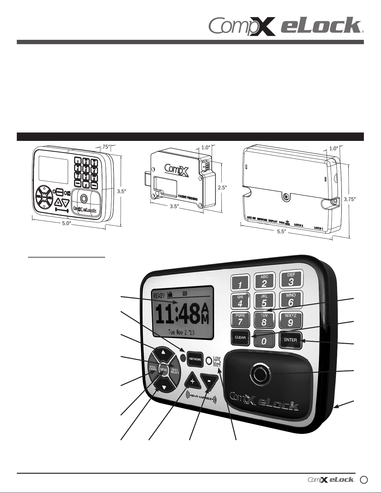
eLock controller
1. Dot matrix LCD
2. Network button (blue LED)
3. “UP” button
4. “NEXT/SELECT” button
5. “BACK/CANCEL” button
6. “MENU” button
7. “DOWN” button
8. + Button
9. - Button
10. Low battery indicator
(yellow LED)
11. Magstripe reader location
(if equipped)
12. HID Prox or HID iCLASS
reader location (if
equipped)
1
2
3
4
5
6
15
14
13
12
11
13. “ENTER” button
14. “CLEAR” button
15. Alpha-numeric keypad
200/300 Series — CompX cabinet eLock Instructions
7
8 9 10
1
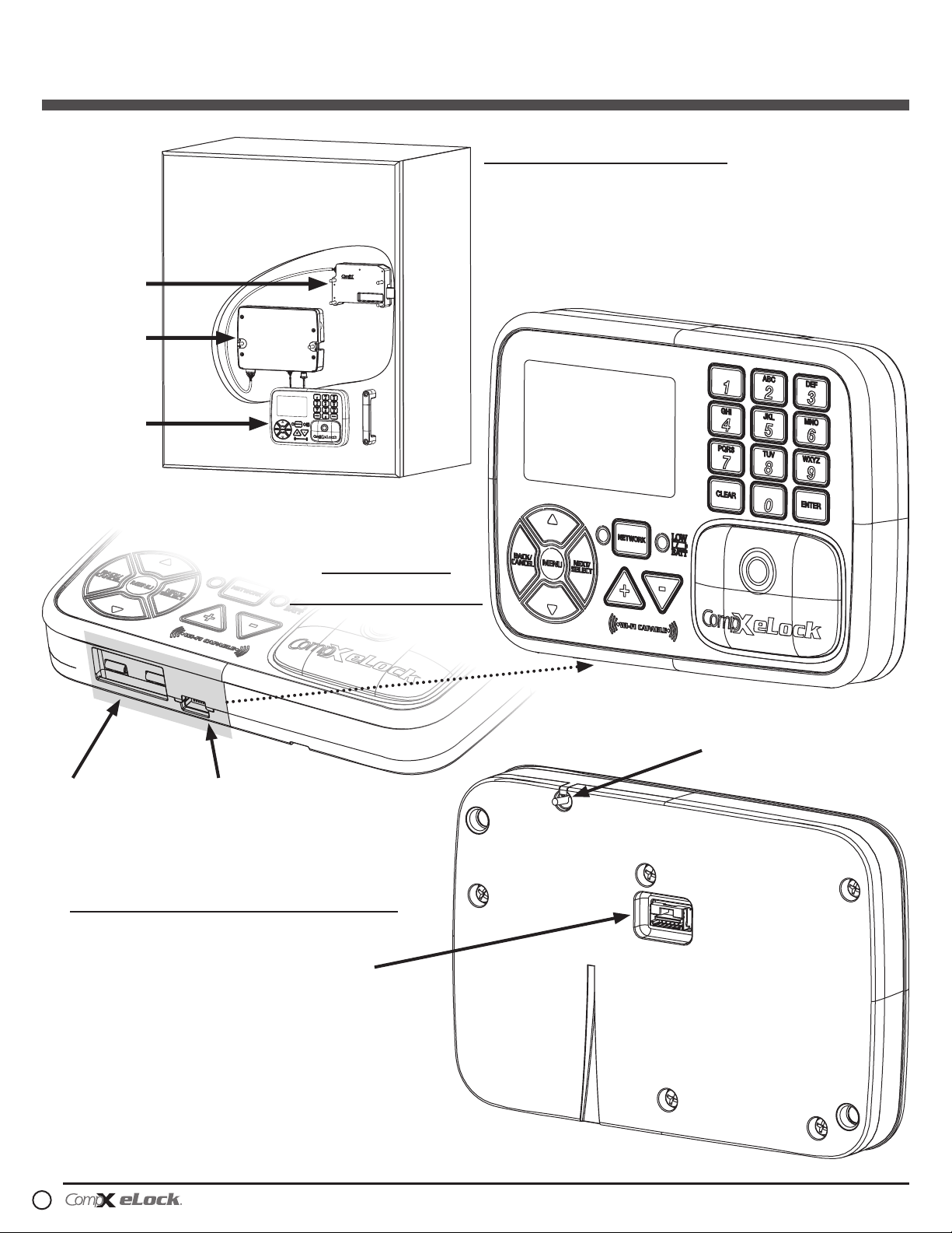
200/300 Series Cabinet eLock — Components
Installation example
Cabinet door installation shown.
eLock can also be installed on
drawers.
latch
battery
compartment
controller
Front view:
eLock controller
9V Battery
Jumper Port
USB Port for direct connection
to LockView software
Back view: eLock controller
Battery cable connector
Integrated Wi-Fi
antenna cable
included for 300
Series Wi-Fi version
200/300 Series Cabinet eLock Components
continued on page 5
2
200/300 Series — CompX cabinet eLock Instructions
200/300 Series Cabinet eLock — Installation
Screws to be used for mounting
eLock controller:
w2 – #10 x ½" philips pan head hi-
low blunt point (type B) SEMS
mounting screw (use on sheet metal
application) – OR –
w2 – #10 x 17/32" philips pan head
hi-low blunt point (type B) SEMS
mounting screw (use on MINIMUM
5
/8" thick application; do not use
on sheet metal application)
1"
WARNING: Print this
page and measure the line
above. It is OnE IncH
LOng. If it measures less
than or more than one inch,
the template measurements
also need to be scaled
accordingly.
FAILURE TO DO SO
COULD RESULT IN
MISDRILLED HOLES.
w4 – #10 x 1½" philips pan head wood
200 & 300 Series
CompX Cabinet eLock
Controller Mounting Template
Drill ½"
through hole
for cable
IMPORTANT: Use template on outside
surface where eLock is to be mounted.
*DRILL FROM THIS SIDE*
Drill 7/32"
through hole
#1
(#1) for
mounting
Screws to be used for mounting
eLock latch:
screw for mounting motorized latch
Drill 3/8" through
hole only if unit
is Wi-Fi
#4
#3
w #1, 2 and 3 are REQUIRED
w #1 and 2 are through holes to mount
the display to the application
w #3 is the through hole to make the
connection between the display and
the interior control module
w #4 through hole is only needed if
the eLock is equipped with wireless
feature (300 Series) “WS-XX-CAB”
200 & 300 Series
CompX Cabinet eLock
Latch Mounting Template
#2
Drill 7/32"
through hole
(#2) for
mounting
200/300 Series — CompX cabinet eLock Instructions
3

template on
opposite page
4
200/300 Series — CompX cabinet eLock Instructions
 Loading...