


VDA-2-HV
1x2 Distribution Amplier
Instruction Manual
Thank you for purchasing one of our products. Please read this manual before using this
product. When using this product, always follow the instructions contained in this manual,
and pay attention to the safety information.

P.O. Box 749 Peekskill, NY 10566 Tel: (845) 737-7009 Fax: (845) 737-0426 Web: www.compuvideosystems.com
Do not expose this product to water, rain or moisture.
Doing this can result in electric shock or re.
Never take this product apart or try to modify it.
Doing so is very dangerous and could result in electric shock.
Do not store this product near open ame.
Do not use this product near open ame or place lit or ammable items, such as
candles, incense, ect., on it.
Do not place any containers lled with water or other liquids near this product.
Doing so could result in re or electric shock if the liquid spills and enters the product or
gets it wet. If a liquid spills near this product, unplug the product immediately.
Do not remove or insert the power supply with wet hands.
Doing so could result in electric shock.
Do not use the power supply in any of the following ways.
Doing so could result in re or electric shock.
Modifying or heating the power cable
Damaging the power cable
Bending or tugging on the power cable unnecessarily
Knotting or kinking the power cable
Setting heavy objects on the power cable
When moving this product , rst unplug the power supply from the outlet. Do not
tug the cable or move this product with the power supply plugged into the outlet.
Doing so could damage the cable, possibly resulting in re or electric shock.
To reduce the risk of electric shock, do not remove the cover.
No parts inside the product can be serviced by the user. If your product needs service
contact:
Compu-Video Systems Inc. at (845) 737-7009.
Usage Environment
Avoid using or storing this product in areas such as those listed below. Doing so could
damage the product or cause it to malfunction.
Areas exposed to heat or ames
Humid areas and areas where water is used
Handling this product
Do not drop or apply a strong force to this product or any included or connected parts.
Do not spill liquids around or inside this product or drop ammable objects around or
inside it.
Power Supply
Only use the supplied power supply which is designed specically for this product.
Do not allow the plug to come into contact with metal or water.
This Product is not designed for contact medical use
Do not use this product for medical applications that could result in patient contact.
The information in this manual is believed to be accurate. It is intended for professional
end users having the skills to evaluate and use the data properly. Compu-Video assumes
no liability in connection with damages incurred while using this product.

P.O. Box 749 Peekskill, NY 10566 Tel: (845) 737-7009 Fax: (845) 737-0426 Web: www.compuvideosystems.com
Mounting Location:
Model Mounting locations:
VDA-2-HV As close to center of the two output feeds or at receiving end
for Ground Loop Blocking
Model # Of Inputs # Of Outputs Controls Special Features
VDA-2-HV 1 2 Gain, High Freq.
Ground Loop
Isolation
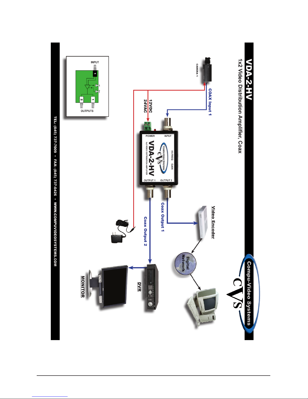
INSTALLATION
The VDA-2-HV is a light weight unit able to be mounted at any location. After the unit has
been placed, you can connect the power.
CONNECTING THE POWER
For the VDA-2-HV, Hum in a video picture can be caused by several things:
A) Ground loop on Video or Common Power Supply
B) Camera
C) Power supply failure
D) Induced hum due to proximity of ac power feeds.
The VDA-2-HV is designed to only reduce or eliminate ground loop
hum between two points and will have minimal to no effect on the
other types of distortion. If you have any splices or bare cables that
may be touching metal between the camera and the VDA-2-HV, isolate
it with tape so that it does not touch any other metal items.
Ground loops usually become visible when several cameras are connected together at a
switcher or a quad screen splitter. The problem also occurs when a camera is located in a
different “ground” plane than the monitor is located in. The hum or interference is caused by
the differences in ground voltages from each device mixing together. By using the
VDA-2-HV to isolate the signal and the ground, the problem is resolved. The VDA-2-HV
corrects the ground-loop problem on the input side of a run, this still leaves a
potential for a ground-loop to occur between the 2 locations on the output side of the
VDA. If this problem should occur on one or both outputs simply add a GLB-ll to one
of the 2 outputs.

P.O. Box 749 Peekskill, NY 10566 Tel: (845) 737-7009 Fax: (845) 737-0426 Web: www.compuvideosystems.com
SIGNAL ADJUSTMENTS
On the VDA-2-HV there are openings on the side of the unit for the gain and high
frequency controls. Insert a small straight edge screwdriver to adjust. Connect a signal
to the video “in” of the unit. With an oscilloscope connected to the output and the output
cable terminated in 75 ohms, adjust the gain control so that the sync signal is 280mv or if a
1VPP test signal is available, adjust the gain control for an overall level of 1VPP at the end
of the cable.
On the VDA-2-HV, the High Frequency control is adjusted for the sharpest picture desired.
Fig. 1
Control Locations
PLACEMENT IN SYSTEM
The VDA-2-HV should be placed as near the end of a system as possible for ground loop
protection. Because of the special isolated power supply system in the VDA-2-HV, it
can be placed wherever a 1x2 DA is needed. For best results on cable compensation, it
should be at the receiving end of a long cable run.
1) Disconnect the feed from the camera at the end by the monitor, switcher or VCR.
Connect the camera feed to VDA-2-HV input. Connect one output to your monitor,
switcher or VCR. and verify that the hum is reduced or eliminated.
2) Adjust the video gain for the desired level
3) Adjust the High Frequency control for the sharpest possible picture.
GAIN High Frequency

Aligning The VDA-2-HV Using The VST-1000
P.O. Box 749 Peekskill, NY 10566 Tel: (845) 737-7009 Fax: (845) 737-0426 Web: www.compuvideosystems.com
To align the VDA-2-HV with out using an oscilliscope use the VST-1000, place the
VST-1000 immediately after the VDA-2-HV. Using the gain or level adjustments on the
VDA-2-HV to match the Gain / Level indicator box color to that of the Gain / Level xed
reference bar box next to it. Once that has been done do the same thing to the HF or High
Frequency control box. If the Variable indicator can not be turned “down” to match the
reference box that is ok.
Camera
DVR

View of what the boxes should look like after being properly adjusted.
P.O. Box 749 Peekskill, NY 10566 Tel: (845) 737-7009 Fax: (845) 737-0426 Web: www.compuvideosystems.com
Gain / Level
Indicator
Gain / Level
Fixed Reference Bar
High Frequency
Indicator
High
Frequency
Fixed
Reference Bar

P.O. Box 749 Peekskill, NY 10566 Tel: (845) 737-7009 Fax: (845) 737-0426 Web: www.compuvideosystems.com
P.O. Box 749 Peekskill, NY 10566 Tel: (845) 737-7009 Fax: (845) 737-0426 Web: www.compuvideosystems.com

P.O. Box 749 Peekskill, NY 10566 Tel: (845) 737-7009 Fax: (845) 737-0426 Web: www.compuvideosystems.com
NOTES

P.O. Box 749 Peekskill, NY 10566 Tel: (845) 737-7009 Fax: (845) 737-0426 Web: www.compuvideosystems.com
NOTES

Compu-Video Systems Inc. warrants this product and all accessories provided with it to be free of
defects in material and workmanship for a period of 5 years from the ORIGINAL date of purchase.
A Purchase receipt or other proof of date of original purchase from Compu-Video Systems Inc. or one
of its Authorized Distributors or Dealers will be required before warranty service is rendered.
Compu-Video Systems reserves the right to audit any claim and to nullify any claim that cannot be
substantiated.
Serial Numbers that have been altered, defaced or removed void this warranty.
This warranty only covers failures due to defect in materials or workmanship, which occur during
normal use. The warranty does not cover damage which occur in shipping of failures which result
from but not limited to faulty installation, set-up adjustments, maladjustment of user controls, improper
operation, power line surge, improper voltage supply, lightning damage, modication, or damage that
is attributed to acts of God or force majeure.
Compu-Video Systems does not warrant, and shall not be responsible for, any lost data or images,
regardless of the cause of the loss. They shall also not be responsible for any costs associated with
removing and installing Compu-Video Systems products.
HOW THE WARRANTY WORKS
If this product, or any of the accessories supplied with it, become defective within the warranty period,
and it is determined that the repair is covered under the warranty Compu-Video Systems Inc. will
repair the product without charge. Overland return transportation from Compu-Video Systems Inc. to
the user is free of charge.
HOW TO GET SERVICE
Please contact CVS by phone for a return authorization number and then return the defective unit,
transportation prepaid and a dated proof of purchase to:
Compu-Video Systems Inc.
37 Arden Drive
Garrison, NY 10524
The customer is responsible for all costs incurred from shipping the product back to Compu-Video
Systems Inc.
OBTAINING TECHNICAL HELP/SERVICE
Web Site: www.compuvideosystems.com
Phone: (845) 737-7009
Fax: (845) 737-0426
In No Event Shall Compu-Video Systems Inc. Be Liable For Consequential Damages
Some states do not allow exclusion or limitation of incidental or consequential damages, so the above
limitation may not apply to you. This warranty gives you specic legal rights, and you may also have
other rights which vary from state to state.
LIMITED WARRANTY
P.O. Box 749
Peekskill, NY 10566
Phone: (845) 737-7009
Fax: (845) 737-0426
 Loading...