

Page 1

VIDEO SWITCHER
VPP404
VPA404
VPA408
Installation and user manual
Page 2

IMPORTANT SAFEGUARDS
READ THE INSTRUCTIONS
Be sure to read all the safety and operating instructions before using the device.
KEEP THE INSTRUCTIONS
Be sure to keep all the safety and operating instructions for possible future need and queries.
FOLLOW THE INSTRUCTIONS
Be sure to follow all the safety and operating instructions.
WATER AND HUMIDITY
Do not use the unit near water – for example near a bath tub, or in any area showing evidences
of humidity.
POWER SUPPLY
This equipment can be fed only by the type of supply quoted by a production code on the device.
Do not overload electric adapters and extension cords as this can result in fire or electric shock.
REPAIR
Do not attempt to open covers and to service this unit yourself, refer all repairs to qualified service
personnel.
UNPACKING
Transfer package is a safe covering for device transportation. We recommend to keep the wrapping for relevant future usage.
VPP404 / VPA404 / VPA408 1
Page 3

TABLE OF CONTENTS INTRODUCTION
INTRODUCTION........................................2
MAIN CHARACTERISTICS........................2
OPERATING ELEMENTS
AND FUNCTIONS ......................................3
INSTALLATION..........................................5
MONITOR OUTPUTS..............................5
ALARM INPUTS......................................5
ALARM OUTPUT....................................5
ALARM CONNECTOR............................5
POWER SUPPLY INPUT........................5
VIDEO SWITCHERS CONTROLLING .......5
BASIC MODE .........................................5
MANUAL SWITCHING ...........................5
AUTOMATIC SWITCHING......................5
MAIN MENU............................................6
CAMERA ACTIVATION...........................6
SWITCHING PERIOD.............................6
ALARM....................................................6
BEFORE LOOKING FOR HELP................8
TECHNICAL SPECIFICATION...................9
Programmable video switchers VPP404,
VPA404, VPA408 is a apparatus, which enables displaying of 4 or 8 cameras on one
output.
The switching can be provided manually or
with the help of programmed sequence. It is
possible to set up cameras, which are at the
right time available for automatic switching.
This makes possible to disconnect temporarily uninteresting or disconnected cameras.
An operator attention can be focused only on
important camera images.
The video switchers VPA404 and VPA408
contains 4 (8) alarm inputs. The video
switchers itself remembers the last setting of
active cameras, a programmed sequence
and the time of switching an alarm output,
even after the unit had been switched off.
MAIN CHARACTERISTICS
o 4 (8) video inputs
o 2 identical video output
o on screen menu control
o programmable switching sequence
for the monitor output
o alarm input for each video input
o potentialless alarm output *
o 2 alarm setting modes *
o acoustic and optical alarm signaling *
* for VPA404 and VPA408 only
VPP404 / VPA404 / VPA408 2
Page 4
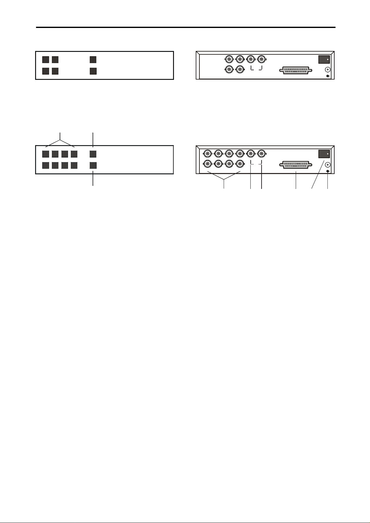
OPERATING ELEMENTS AND FUNCTIONS
1
2
3
4
56789
Pict.1: Front panel VPP404 / VPA404
12SEQ
MENU34
VPA404
4 CHANNEL VIDEO SWITCHER
Pict.2: Front panel VPA408
1324SEQ
MENU5768
VPA408
8 CHANNEL VIDEO SWITCHER
1. 1 - 8
Press the button 1 – 8 to display the appropriate camera image.
2. SEQ
Press the button SEQ to start the automatic
camera switching, according to the programmed sequence.
3. MENU
Press the button MENU to display the control
menu on the screen.
4. IN1 – IN8
Video inputs for cameras 1 – 8.
Pict.3: Back panel VPA404
IN 1
IN 3
IN 4IN 2
12
MON
ALARM
POWER
12V
-
+
Pict.4: Back panel VPA408
IN 1
IN 3IN 5IN 7
IN 8IN 6IN 4IN 2
5. MON 1
Main video output.
6. MON2
Spot video output.
7. ALARM
Connector for connecting alarm inputs and
outputs. This connector enables connecting
of alarm contact makers, sensors, etc.
8. POWER
Press the switch POWER to start the video
switchers.
9. 12V
Connector for connecting power supply.
12
MON
ALARM
POWER
12V
-
+
VPP404 / VPA404 / VPA408 3
Page 5
OPERATING ELEMENTS AND FUNCTIONS (continuation)
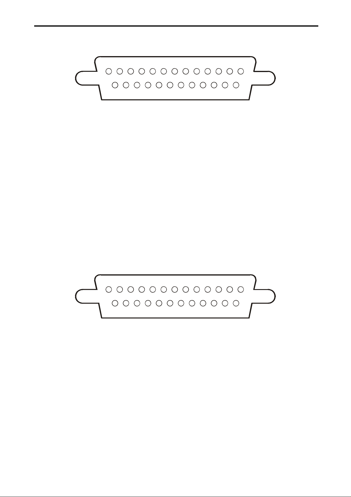
Pict. 5: Alarm connector CANNON 25 for VPA404
131211109876543
(1) Alarm output – normally open contact 1
(2) Reserve
(3) Alarm input 1
(4) Alarm input 3
(5) Reserve
(6) Reserve
(7) Common conductor – ground (GND)
(8) Reserve
(9) Reserve
(10) Reserve
(11) Reserve
(12) Common conductor – ground (GND)
(13) Common conductor – ground (GND)
Pict. 6: Alarm connector CANNON 25 for VPA408
21
141516171819202122232425
(14) Alarm output – normally open contact 2
(15) Reserve
(16) Alarm input 2
(17) Alarm input 4
(18) Reserve
(19) Reserve
(20) Common conductor – ground (GND)
(21) Reserve
(22) Reserve
(23) Reserve
(24) Reserve
(25) Common conductor– ground (GND)
131211109876543
(1) Alarm output – normally open contact 1
(2) Reserve
(3) Alarm input 1
(4) Alarm input 3
(5) Alarm input 5
(6) Alarm input 7
(7) Common conductor – ground (GND)
(8) Reserve
(9) Reserve
(10) Reserve
(11) Reserve
(12) Common conductor – ground (GND)
(13) Common conductor – ground (GND)
21
141516171819202122232425
(14) Alarm output – normally open contact 2
(15) Reserve
(16) Alarm input 2
(17) Alarm input 4
(18) Alarm input 6
(19) Alarm input 8
(20) Common conductor – ground (GND)
(21) Reserve
(22) Reserve
(23) Reserve
(24) Reserve
(25) Common conductor – ground (GND)
4
VPP404 / VPA404 / VPA408
Page 6

INSTALLATION SWITCHERS CONTROLLING
MONITOR OUTPUTS
Outputs VIDEO SWITCHERS and MAIN are
individual video outputs for connecting monitor. For the correct function of the connected
apparatus the signal cables must have the
impedance load of 75Ω.
ALARM INPUTS
One alarm input is suitable for one video
input. Alarm loops are connected between
alarm input and common conductor - ground
(GND).
ALARM OUTPUT
Video switchers has its own potentialless
alarm output made of the normally open contacts of the relay.
ALARM CONNECTOR
Alarm connector is used for connecting
alarm inputs and outputs. The connection of
25 outlet connector CANNON is illustrated on
the pictures 5 and 6 (page 4).
POWER SUPPLY INPUT
The video switchers VPP404, VPA404 and
VPA408 are supplied from a uniflow supply
of 12 V. Energy input is 4 W maximum. For
connecting supply voltage is used a concentric connector 5,5 x 2,1 mm. The positive
supply pole is on the inside contact of the
concentric connector, the connector jacket is
the negative pole.
BASIC MODE
After turning on, the video switchers cyclically switches among active cameras according to the sequence, which has been set up.
The automatic switching is signaled by the
SEQ light-emitting diode (LED), the camera
displayed on the main video output (MAIN) is
signaled by the diode of the buttons 1 – 8.
MANUAL SWITCHING
Press the corresponding button to display
cameras 1 – 8.
AUTOMATIC SWITCHING
The automatic switching starts by pressing
the button SEQ.
If the video switchers does not start to switch
automatically, check the camera settings in
the menu SEQUENCE and TIME (page 6).
VPP404 / VPA404 / VPA408 5
Page 7
VIDEO SWITCHERS CONTROLLING (continuation)
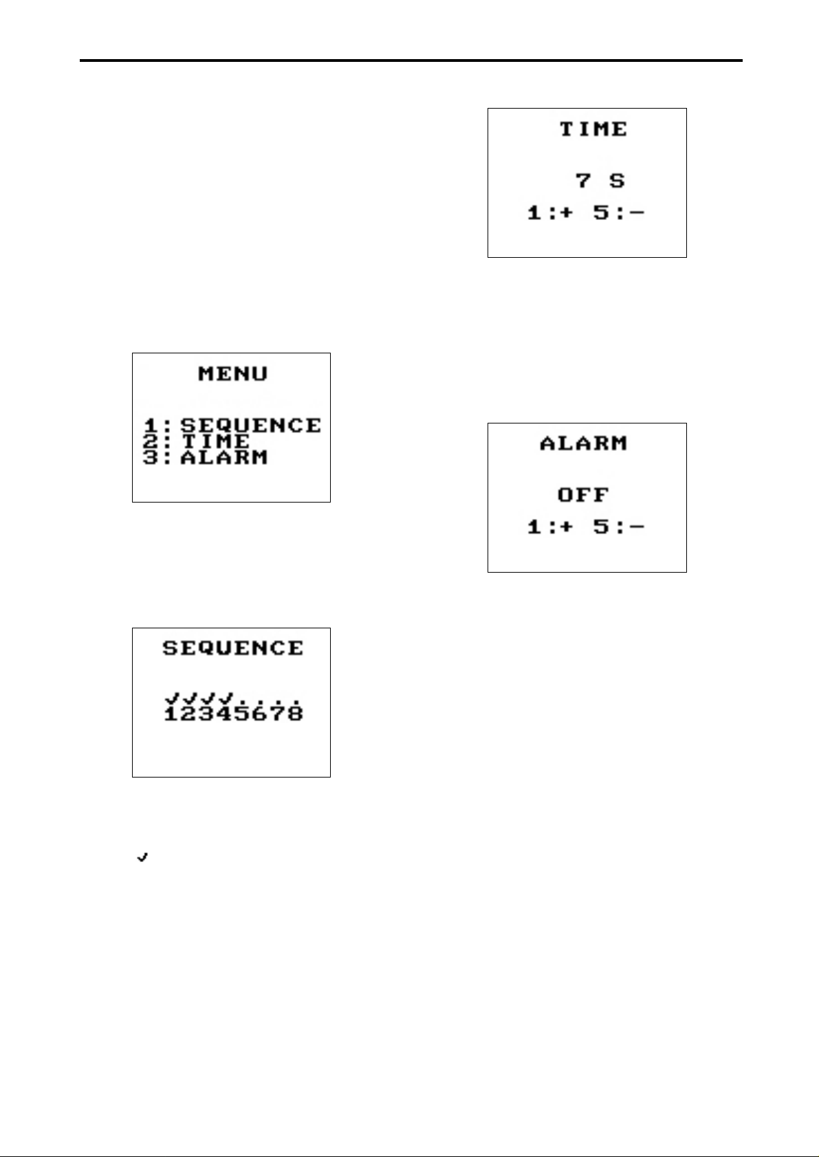
Video switchers contain a graphical menu,
which enables the setting of the following
functions.
o Cameras activation for automatic
switching
o Switching period set up
o Alarm functions set up
MENU - MAIN MENU
To display the main menu on the screen
press the button MENU. Choose the required
function by pressing the buttons 1, 2 and 3.
TIME – SWITCHING PERIOD
By using the buttons 1 and 3 (1 and 5 by
Q8M) is possible to prolong or slow down the
switching time among individual cameras
and video switchers pictures, at intervals 1 –
99 sec.
ALARM – ALARM SET UP
SEQUENCE – CAMERAS ACTIVATION
By pressing the button 1 is the menu for
cameras activation and deactivation for
automatic switching displayed.
By pressing the buttons of individual cameras activate or deactivate automatic switching cameras. Activated cameras are marked
by sign .
If the cameras are set up, the video switchers will switch automatically among cameras
1, 2, 3, 4, …
In case you make a mistake by sequence
programming (none or only one camera is
active) and you start the switching sequence
by pressing the button SEQ on the front
panel, notice „INCORRECT SEQUENCE“
will appear. In that case is necessary to set
up cameras in the SEQUENCE menu properly.
The video switchers detects an alarm, when
the connection is provided between the
alarm input 1 – 8 on the CANNON connector
of the back panel and the common conductor – ground (GND). By the help of the buttons 1 and 3 (1 and 5 Q4M) set up video
switchers reaction for an alarm. The reaction
can be:
OFF - alarm is off - video switchers
does not respond to the alarm.
FOLLOW - video switchers signalizes an
alarm as long as any alarm input is active.
2-255 S - video switchers signalizes an
alarm for the set up time since
the alarm event had occurred.
If an alarm occurs, the video switchers
makes the following steps:
1. it switches the alarm output (relay) – signaled acoustically (beep).
2. it switches a camera corresponding to the
alarm input for the set up time.
The alarm stops after the end of the set up
time interval, after pressing any button or
VPP404 / VPA404 / VPA408 6
Page 8

INSTALLATION SWITCHERS CONTROLLING
after the end of the alarm event in the mode
FOLLOW.
VPP404 / VPA404 / VPA408 5
Page 9

VIDEO SWITCHERS CONTROLLING (continuation)
YOUR TROUBLE THE CAUSE AND ITS SOLUTION
After connecting the supply voltage device does
not work.
After connecting the supply voltage the LEDs are
on, but the device does
not work.
Automatic switching sequence cannot be
switched on.
Device does not react to
alarm inputs.
There is no picture on the
monitor.
The power supply is not connected.
Check the supply connector and the polarity of power supply.
Switch on the power breaker.
The supply adapter is not dimensioned sufficiently.
Check if the adapter power output and voltage agree with the
video switchers requirements.
The supply adapter is not dimensioned sufficiently.
Check if the adapter power output and voltage agree with the
video switchers requirements.
Cameras listed in the switching sequence are off from the switching.
Correct the sequence and check the sequence period (page 6).
The alarm processing is switched off in the main menu.
Set up the alarm with the function of ALARM (page 6).
The connection of the alarm signals is disconnected.
Check the connection of the alarm connector.
The video switchers and monitor patchcord is defective.
Check the patchcord carefully.
VPP404 / VPA404 / VPA408 6
Page 10

Page 11

Number:
Amplitude:
Input impedance:
Connectors:
Number:
Amplitude:
Connector:
Number:
Loop connection:
Activity:
Maximum alarm loop impedance:
Connector:
Output:
Maximum switching voltage:
Maximum switching current:
TEMPERATURE CONDITIONS
Range of operating temperatures:
Humidity:
Input voltage:
Power consumption:
Connector:
MECHANICAL PARAMETERS
Dimensions:
Weight:
Alarm connector mate + cover:
TECHNICAL SPECIFICATION
VIDEO INPUTS
4 (8 by VPA408)
0,75 - 1,5 V
75 Ω
BNC
VIDEO OUTPUTS
2 identical
1 V
load 75 Ω
p-p
BNC
ALARM INPUTS
4 (8 by VPA408)
input – ground (GND)
normally open
1 kΩ
CANNON 25 pin socket
ALARM OUTPUT
2 low voltage relay contacts
40 V
0,5 A
0 – 40 °C
max. 85 %
POWER SUPPLY
12 VDC
max. 4 W
Concentric 5,5 × 2,1 mm
218(W) × 44,5(H) × 230(D) mm
1,4 kg
ACCESSORIES
1 p for VPA404 and VPA408 only
p-p
VPP404 / VPA404 / VPA408 8
Page 12

2000 COMPUTRONIC
Printed in the Czech Republic
Producer reserves the right to alternation without prior notice
 Loading...