

Page 1

ENGLISH
BLACK&WHITE AND COLOUR MULTIPLEXERS
Installation and user manual
TP4MD TP10MD TP16MD
TP4CD TP10CD TP16CD
Page 2

Page 3

IMPORTANT SAFEGUARDS
TP4MD/CD / TP10MD/CD / TP16MD/CD 1
ENGLISH
READ THE INSTRUCTIONS
Be sure to read all the safety and operating instructions before using the device.
KEEP THE INSTRUCTIONS
Be sure to keep all the safety and operating instructions for possible future need and queries.
FOLLOW THE INSTRUCTIONS
Be sure to follow all the safety and operating instructions.
WATER AND HUMIDITY
Do not use the unit near water – for example near a
bathtub, or in any area showing evidences of humidity.
POWER SUPPLY
This equipment can be charged only by the type of
supply quoted by a production code on the device. Do
not overload electric adapters and extension cords as
this can result in fire or electric shock.
REPAIR
Do not open covers and repair this unit yourself, refer
all repairs to a qualified person.
UNPACKING
Transfer package is a safe cover for device transportation. We recommend keeping the wrapping for possible future usage.
TABLE OF CONTENTS
INTRODUCTION ...............................................2
MAIN CHARACTERISTICS...............................2
OPERATING ELEMENTS
AND FUNCTIONS .............................................2
CAN & RS 485, RS 232 INTERFACE ................4
EXTERNAL KEYBOARD................................4
MULTIPLEXER NETWORKING .....................4
MULTIPLEXER CONTROLLING.......................5
CAMERA DISPLAYING - LIVE.......................5
PLAYBACK - PLAY........................................5
DIGITAL ZOOM - ZOOM................................5
PICTURE RECORDING - REC ......................5
ANALOGUE CHANNEL CONTROLL. - SEQ..5
DISPLAYING VCR INPUT - VCR ...................5
SELECT VIEW - VIEW ...................................5
TELEMETRY CONTROLLING .......................5
FREEZE PICTURE - HOLD ...........................6
LOAD MACRO - MACRO...............................6
ALARM STATUS - ALARM ............................6
LIST OF EVENTS ..........................................6
MENU................................................................7
MAIN MENU ..................................................7
VIDEORECORDER ......................................7
VCR TYPE ..................................................7
VCR MODE .................................................7
USER DEFINED VCR..................................7
AUX INPUT..................................................8
CAMERA........................................................8
RECORDED CAMERAS ..............................8
DISPLAYED CAMERAS...............................8
DETECTED CAMERAS ...............................8
CAMERAS IN SEQUENCE ..........................8
SEQUENCE.................................................9
TIME MULTIPLIER ......................................9
CAMERA TITLES.........................................9
TELEMETRY ADDRESSES.........................9
PICTURE PARAMETERS ............................9
ALARM.........................................................10
ALARM INPUTS.........................................10
DWELL TIME.............................................10
RECORDING .............................................10
PLAYBACK................................................10
DISPLAY....................................................11
RELAY CONTACTS...................................11
SPEAKER ................................................. 11
ACTIVITY DETECTOR ................................ 12
SENSITIVITY ............................................12
LIGHT–SENSITIVITY MATRIX .................. 12
WALK TEST.............................................. 12
DWELL TIME ............................................ 12
MACRO ....................................................... 13
MACRO 1-8............................................... 13
SCHEDULER............................................... 13
EDIT SCHEDULER ................................... 13
ENABLE SCHEDULER.............................. 13
EVENTS....................................................... 14
ALARM...................................................... 14
CAMERA FAIL........................................... 14
ACTIVITY DETECTION............................. 14
CAMERA EVENTS.................................... 14
DISPLAY LIST........................................... 14
CLEAR LIST.............................................. 14
SYSTEM ...................................................... 14
PASSWORD ............................................. 14
TIME AND DATE....................................... 15
CORRECTION ......................................15
FORMAT ............................................... 15
LANGUAGE .............................................. 15
DISPLAY ................................................... 15
START - UP .............................................. 16
TELEMETRY............................................. 16
DOWNLOAD FIRMWARE ......................... 16
RELOAD FACTORY SETTING .................. 16
INFO ......................................................... 16
BEFORE LOOKING FOR HELP ..................... 17
TECHNICAL SPECIFICATION........................ 19
Page 4
INTRODUCTION MAIN CHARACTERISTICS
2 TP4MD/CD / TP10MD/CD / TP16MD/CD
ENGLISH
Multiplexers TP are devices, which enable recording
and decoding of up to 16 TV signals (cameras) on the
VCR. They also offer the simultaneous displaying of
all cameras on a divided screen in a number of displaying formats – views.
The multiplexers have two digital channels. The main
channel is used for LIVE display or for playback of
recorded pictures. The recording channel is used only
for recording.
The multiplexers have RS 485 and the CAN interface,
which enables to control the telemetry receivers used
for controlling the PAN/TILT camera heads and zoom
lenses.
For optimum camera recording on VCR it is possible
to use the activity detector. The activity detector enables to affect the camera recording or displaying cameras with detected motion.
The multiplexers have not only a digital channel, but
also an analogue channel, which contains a sequential switcher with the programmable order and time of
cameras switching. The spot channel is used even for
manual controlling from the main panel.
o 4, 10 or 16 video inputs
o main and spot output
o VCR input and output
o automatic TV standard detection from connected
cameras
o 864 samples per a TV line CCIR/PAL (856 -
EIA/NTSC)
o 576 active TV lines CCIR/PAL (480 – EIA/NTSC)
o 256 grey scale / 16 million colours
o RS 485 and CAN interface for telemetry control-
ling of pan/tilt units and zoom lenses
o possibility of controlling from external keyboard
o displaying of 1, 2, 3, 4, 7, 8, 9, 10, 13, 16 came-
ras on divided screen
o digital zoom
o picture freeze
o user friendly on-screen menu
o on-screen time, date, titles and status
o programmable switching sequence for spot and
main monitor
o built-in activity detector
o 4, 10 or 16 alarm inputs
o potentialless alarm output
o wide range of alarm settings
o acoustic and optical alarm signalling
o recording of alarm events
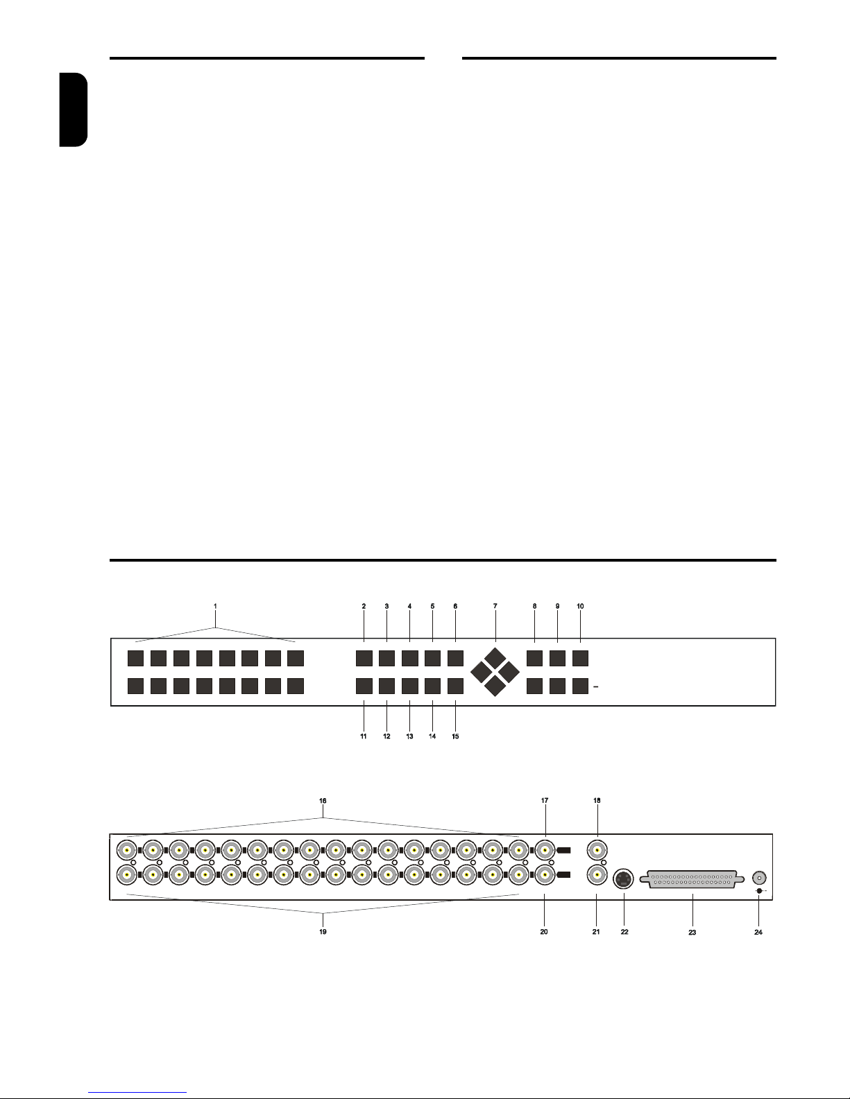
OPERATING ELEMENTS AND FUNCTIONS
Fig. 1: Front panel of TP16CD
ZOOM
FOCUS
IRIS
VIEW
MACRO
ALARM
AUTO PRESET9 10 11 12 13 14 15 16
1 2 3 4 5 6 7 8
MENU
SEQPLAYHOLDREC
+
16 CHANNEL MULTIPLEXER
TP16CD
Fig. 2: Back panel of TP16CD
10111213141516 9 8 7 6 5 4 3 2 1
VCR
SPOT
+
ALARM
DC 12V
MAIN
IN
OUT
Page 5
MULTIPLEXER CONTROLLING
3 TP4MD/CD / TP10MS/MD/CD / TP16MS/MD/C
ENGLISH
1. 1-16
Press the buttons 1 - 16 to display the corresponding camera image.
2. REC
Press the button REC to start recording to the
VCR.
3. HOLD
Press the button HOLD to freeze all cameras on
the divided screen.
4. PLAY
Press the button PLAY to start the playback from
the VCR.
5. SEQ
Press the button SEQ to control an analogue channel MON SPOT.
6. MENU
Press the button MENU to display the on-screen
menu.
7. DIRECTION ARROWS
These buttons are used for moving in the menu
and for controlling the pan/tilt camera heads and
zoom lenses in telemetry.
8. ZOOM +/-
By pressing the buttons ZOOM it is possible to
control the digital zoom (PLAY mode only) and the
optical zoom for telemetry.
9. FOCUS +/-
Focus controlling buttons for telemetry
10. IRIS +/-
Iris controlling buttons for telemetry
11. VIEW
After pressing the button VIEW it is possible to select various types of displaying of the camera
numbers on the screen.
12. MACRO
Press the button MACRO to load the defined macros.
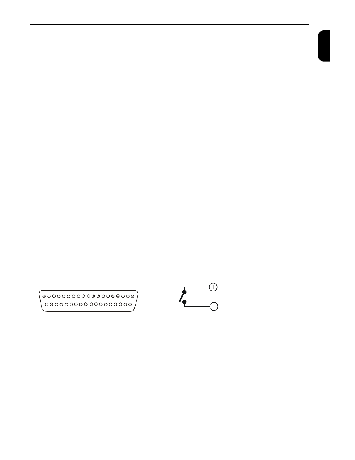
Fig. 3a: D-SUB37M alarm connector
18
17 16
151413 12
11
10
763
20
21
22
232425
26
27
2829
30
31
32
3334
3537
13. ALARM
Press the button ALARM to display the alarm
status. Press the button again to display the list of
alarm events.
14.AUTO
Press the button AUTO to starts/stop the auto
matic camera switching, according to the pro grammed sequence.
15. PRESET
By pressing the button PRESET it is possible to
set up prepositions of the connected devices. This
button has more telemetry functions.
16. IN1 – IN16
Video inputs for cameras 1 – 16.
The video inputs are automatically terminated if the
corresponding video output is left unconnected. If a
device is connected to video out make sure that it
is properly terminated.
17. VCR IN
Use this video input for connecting from VCR.
18. SPOT
Video output to spot monitor.
19. OUT1 – OUT16
Video outputs for cameras 1 – 16.
20. VCR OUT
Video output to VCR.
21. MAIN
Video output to main monitor.
22. MAIN
S-VHS video output to main monitor ( only for colour multiplexers ).
23.ALARM
Connector serve for RS 485, RS 232 and CAN interfaces and enables connecting alarm contact
makers, sensors, ect.
24. DC12V
Connector for connecting power supply (12VDC,
min 700mA).
Fig. 3b: Alarm output internal connection
Contact 1
20
Contact 2
(1) Alarm output – contact 1
(2) Reserve
(3) Common input conductor – ground (GND)
(4) Alarm input 1
(5) Alarm input 3
(6) Alarm input 5 (TP10, TP16)
(7) Alarm input 7 (TP10, TP16)
(8) Alarm input 9 (TP10, TP16)
(9) Alarm input 11 (TP16)
(10) Alarm input 13 (TP16)
(11) Alarm input 15 (TP16)
(12) Common input conductor – ground (GND)
(13) RS 232 RX
(14) RS 232 TX
(15) CAN terminating resistance
(16) CAN_L, connect to twist pair cable conductor
(17) Common input conductor – ground (GND)
(18) RS 485 A (+)
(19) RS 485 terminating to use connect with (18)
(20) Alarm output – contact 2
(21) Common input conductor – ground (GND)
(22) AUX input from VCR
(23) Alarm input 2
(24) Alarm input 4
(25) Alarm input 6 (TP10, TP16)
(26) Alarm input 8 (TP10, TP16)
(27) Alarm input 10 (TP10, TP16)
(28) Alarm input 12 (TP16)
(29) Alarm input 14 (TP16)
(30) Alarm input 16 (TP16)
(31) Common input conductor – ground (GND)
(32) RS 232 RTS
(33) RS 232 CTS
(34) CAN_GND, connect to shielding of the cable
(35) CAN_H. connect to twist pair cable conductor
(36) RS 485 B (-)
(37) CAV_V+, (5V/100mA) – do not connect
Page 6
CAN & RS 485, RS 232 INTERFACE
4 TP4MD/CD / TP10MD/CD / TP16MD/CD
ENGLISH
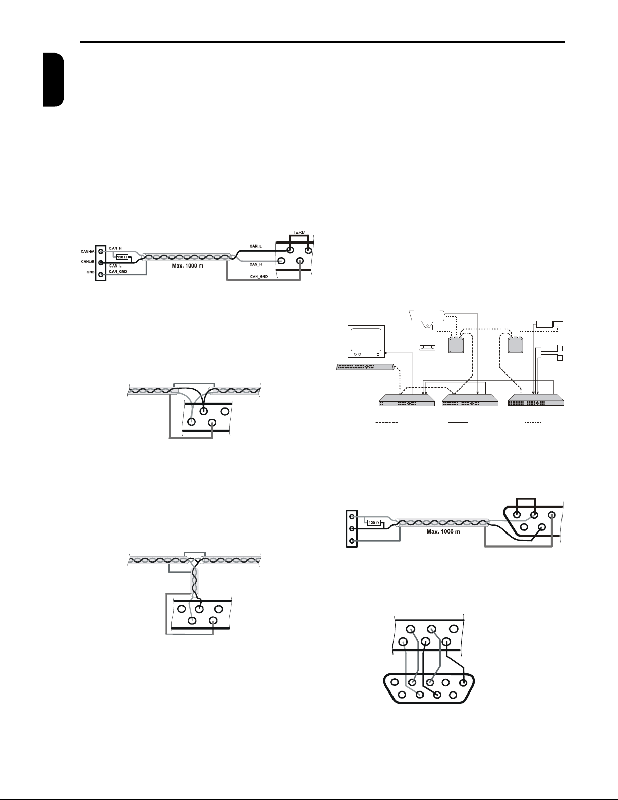
The external devices (PAN/TILT camera heads,
lenses) are connected to the multiplexer using the RS
485 and the CAN interface. The devices are connected with shielded twisted pair cable.
Basic connection of two devices on the CAN bus is
shown at figure 4. (Connection of the multiplexer and
the telemetry receiver TC is used as the example).
Length of the CAN bus can be 1000 m at maximum
and both ends of the bus must be terminated with
120 W resistor.
Fig. 4: Connection of terminal devices of the CAN bus
35
341615
TC - telemetry receiver
Terminal board K3
CAN Bus
(Shielded twist pair cable)
Multiplexer
Konektor D-SUB
Figure 5 shows the connection of other devices on the
CAN bus. It is possible to connect up to 90 devices in
this way. If you need to connect more devices, it is
necessary to use the CAN bus hub.
Fig. 5: Connection of next device of the CAN bus
CAN_H
CAN_L
CAN_GND
CAN_GND
16
153534
If it is not possible to connect the device directly to the
bus (fig. 5), you can connect it using a stub (fig. 6).
The length of one stub must be 60 m at maximum.
The whole length of all stubs must not exceed 300 m.
Other connection possibilities can be reached using
the CAN bus hub.
Fig. 6: Connection using the stub
CAN_H
CAN_L
CAN_GND
CAN_GND
CAN_GND
Stub
Max. 60 m
161535
34
EXTERNAL KEYBOARD
The external keyboard enables remote controlling of
other external equipment (multiplexers, PAN/TILT
camera heads, lenses) connected to the CAN bus.
You can connect several external keyboards to CAN
bus and control different or the same devices. During
controlling of one device by several keyboards you
are able to operate controlled device by another keyboard five seconds after the last command of the pre-
vious keyboard (it is not possible to control one device
from two keyboards at the same time).
MULTIPLEXERS NETWORKING
Using the external keyboard and auxiliary video
switcher you can simply control several multiplexers
from one external keyboard. So it is possible to control
a group of multiplexers or cameras and watch their
outputs on one monitor. You can use a multiplexer
sequential switcher instead of a video switcher. At
fig. 8 you can see the use of the multiplexer no. 3
analogue sequential switcher as an auxiliary video
switcher. Video outputs of multiplexers no. 1 and 2
lead to video inputs 1 and 2 of the multiplexer no. 3.
For example, when the external keyboard starts to
control multiplexer no. 2, it also sends a command to
the multiplexer no. 3 to display output of the multiplexer no. 2 to the monitor. You can use the unused
video inputs of the multiplexer no. 3 for recording or
displaying on a divided monitor screen.
Fig. 8: Multiplexers networking example
TERMINATOR
CAN BUS VIDEO SIGNAL
LENS, PAN/TILT
TERMINATOR
P/T UNIT
TC
EXTERNAL KEYBOARD
MONITOR
TP4MD
TP16MS
TELEMETRY
RECEIVER
TELEMETRY
RECEIVER
TC
CAMERA
WITH ZOOM LENS
CAMERA
WITH ZOOM LENS
MULTIPLEXER 3
MULTIPLEXER 2
CAMERA
CAMERA
KB 1
TP16CD
MULTIPLEXER 1
Fig. 9: Connection of RS 485 bus
36
18
17
TERM
37
19
B-
A+
B-
A+
GND
Fig. 10: Connection of RS 232 for download
7
2
3
6
1
Multiplexer D-SUB
PC RS 232
14
13
33 32 31
5
948
Page 7
MULTIPLEXER CONTROLLING
TP4MD/CD / TP10MD/CD / TP16MD/CD 5
ENGLISH
CAMERAS DISPLAYING – LIVE
The camera displaying is an implicit mode, which is
started after the device has been switched on. Cameras are displayed according to the last chosen view.
Set up camera to the first position by pressing the
corresponding button 1 to 16; the following cameras
are arranged automatically. If the camera was at the
first position, it will be displayed at full screen. The TP
multiplexers omit the displaying of the disabled cameras, that provides the better compatibility of displaying without empty frames among the cameras.
The first camera has the privilege of the zooming
function (ZOOM - PLAY mode only) and telemetry
controlling.
Pressing the button AUTO it switches the automatic
switching sequence on or off. Set up the sequence
parameters using the menu Sequence, Displayed
cameras and Time multiplier (see page 8 and 9).
PLAYBACK RECORDING - PLAY
The playback of the coded record from the VCR is
switched ON by pressing the PLAY button. The cameras are displayed on the screen of the main channel
according to the topical view in this mode.
Pressing the button 1 to 16 set up the particular camera to the first view position; the following cameras are
arranged automatically. The function of zooming
(ZOOM) is always available only for the first camera.
By another pressing the button PLAY, the multiplexer
switches into the LIVE mode.
DIGITAL ZOOM - ZOOM
Digital picture zoom can be switched on only in the
PLAY mode by pressing the button ZOOM+. When
you are using the zoom function, only the centre of the
whole picture is displayed on the monitor screen. The
picture can be moved using the direction arrows.
When the zoom is on, the title ZOOM is displayed on
the monitor status line. The zoom can be set up only
on the main channel. The digital zoom will be turned
off by pressing the button ZOOM- or ZOOM+.
PICTURE RECORDING - REC
The recording of the coded images is switched on by
pressing the button REC and it is indicated by red
point in the status line. Recording uses its own independent channel without affecting the main channel.
Another pressing the REC button stops recording.
ANALOGUE CHANNEL CONTROLLING - SEQ
Controlling a spot analogue channel is switched on by
pressing the button SEQ. The buttons 1 to 16 are
used for displaying a corresponding camera, by pressing the button AUTO it is switched the automatic
switching sequence on or off. Set up sequential
switching parameters using the menu Sequence,
Cameras in sequence and Time multiplier (see page 8
and 9). By another pressing the button SEQ, the multiplexer switches back into the controlling of the main
channel.
DISPLAYING VCR INPUT - VCR
When playback does not work as expected, it is
probably caused by missing or improper signal at
VCR IN input.
Press and hold the PLAY key for at least 2 seconds to
display signal from VCR IN to the monitor controlled at
the moment. If you control LIVE or PLAY mode, the
picture is processed digitally (as real playback), when
you control analogue channel, the signal is displayed
as it is to the analogue output.
Releasing the PLAY key returns the multiplexer to its
previous mode.
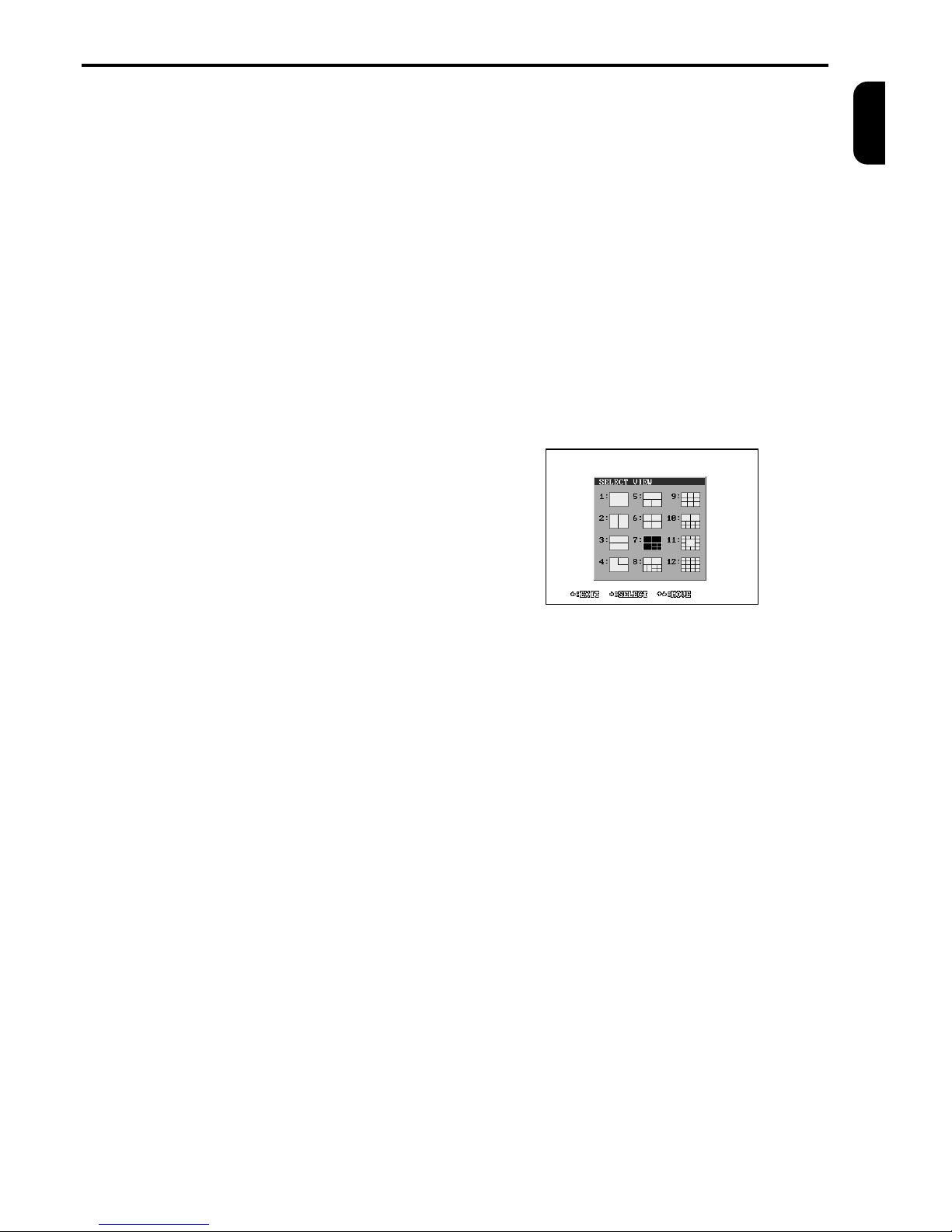
SELECT VIEW – VIEW
The view on the main monitor can be selected by
pressing the VIEW button. On the monitor screen the
following menu will be displayed and than the demanded view can be chosen by pressing the button 1
to 12. Only the first 6 displayed possibilities are available for 4 channel multiplexers and only the first 10 for
10 channel multiplexers.
TELEMETRY CONTROLLING
TP multiplexers offer remote controlling of cameras
using the RS 485 and the CAN interface. If a split
screen is being displayed, you can control the first
camera of the view (left top corner of the view or the
centre at the view no. 11). Only cameras with telemetry receiver address set up can be controlled. This
address is set up in the menu Telemetry addresses
(see page 9).
PAN/TILT unit and lens controlling:
PAN/TILT camera heads are controlled using the direction buttons. The lens is controlled using the buttons ZOOM +/-, FOCUS +/-, IRIS +/-. Automatic focus
or iris is turn on by pressing the buttons PRESET,
AUTO, FOCUS+ or IRIS+, if camera support this.
Automatic function is turn off by start of manual controll.
User AUX outputs controlling:
Multiplexer can control 2 user outputs (AUX1 and
AUX2) of the telemetry receiver. The user outputs
controlling is possible with the use of the buttons
PRESET (the button starts flashing) and one of the
buttons ZOOM. Allocation of the individual user outputs AUX to the buttons is as following:
AUX1 – ZOOM+
AUX2 – ZOOMThe output function can be set up in the menu Tele-
metry (see page 16).
Page 8
MULTIPLEXER CONTROLLING (continued)
6 TP4MD/CD / TP10MD/CD / TP16MD/C
ENGLISH
Multiplexers TP can set up a so-called preposition (in
advance programmed position of PAN/TILT camera
heads and zoom lenses).
Preposition invoking:
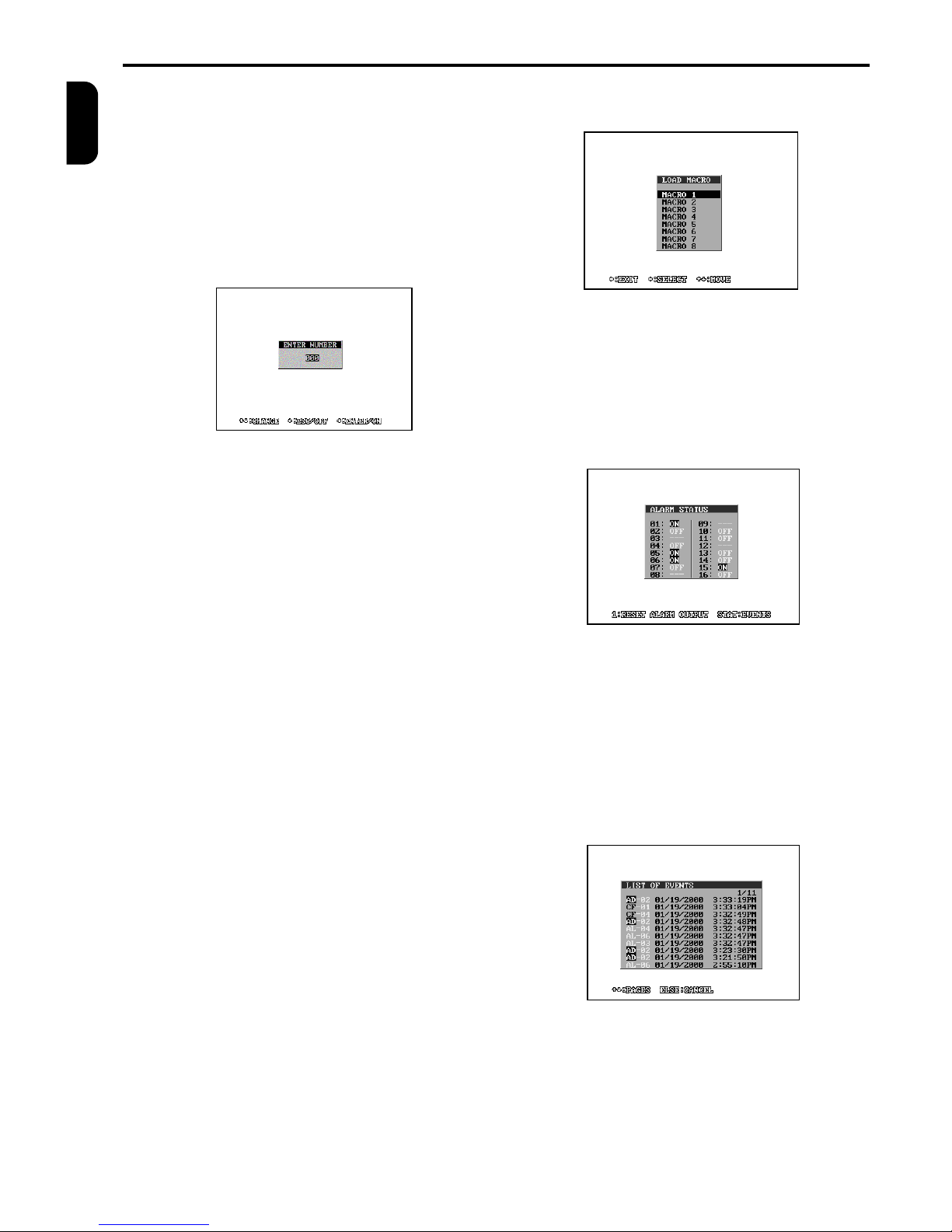
Pressing the button PRESET, PLAY and enter the
number within the displayed rectangle and confirm.
Although the number can be set up to 999, the range
depends on the camera possibilities (please see its
manual). The PAN/TILT camera heads and the zoom
lens will be set up into the in advance saved preposition.
Preposition saving:
Pressing the buttons PRESET, REC and the number
subsequently the preposition can be saved. After that
the topical position of the PAN/TILT camera heads
and zoom lens is saved into the telemetry receiver
memory.
Cameras OSD menu:
The cameras OSD menu can be disabled in the menu
Telemetry (see page 16), so if you are using the cameras menu be sure the function is enabled.
For show the cameras menu press the buttons
PRESET, MENU. On the status line the “PRESET” is
displayed. The arrow buttons (¬ - ¯ ®) are used for
moving in the menu. However in some special cases
must be used another buttons according to displayed
instructions. If number entering is required, this could
be done by long pressing PLAY button.
After leaving the cameras menu and pressing the
PRESET button you return back to the pan/tilt and
lens controlling mode. After that the “PRESET” disapears from the status line.
FREEZE PICTURE (HOLD)
During LIVE and PLAY modes pressing the button
HOLD freezes the main channel monitor view. The
picture starts to move again by other pressing of this
LOAD MACRO (MACRO)
TP multiplexers enable to define so-called macros.
Macro is a set of parameters, which change the multiplexer settings when the macro is launched.
The following menu is displayed after pressing the
button MACRO.
A particular macro is switched on by pressing the
button of 1 to 8 and it changes prepared parameters.
The intended parameters can be set up in the menu
Edit macro (see page 13).
DISPLAY ALARM STATUS (ALARM)
By pressing the button ALARM the following table is
displayed, which represents actual status of all alarm
inputs.
In case the alarm output (relay) is active, you can
switch it off by pressing the button 1. If you press the
button ALARM again, the list of recorded events is
displayed.
DISPLAY LIST OF EVENTS
There is displayed a list of events in this menu, which
correspond to the parameters set up in the menu
EVENTS (page 14). The events are displayed from
the last recorded one. They are displayed ten on each
page. Pages can be listed by buttons - and ¯.
Error message notation is as following:
CF - Camera fail (video signal lost)
AD - Activity detection
AL - Alarm event (alarm inputs)
Page 9
MENU
TP4MD/CD / TP10MD/CD / TP16MD/CD 7
ENGLISH
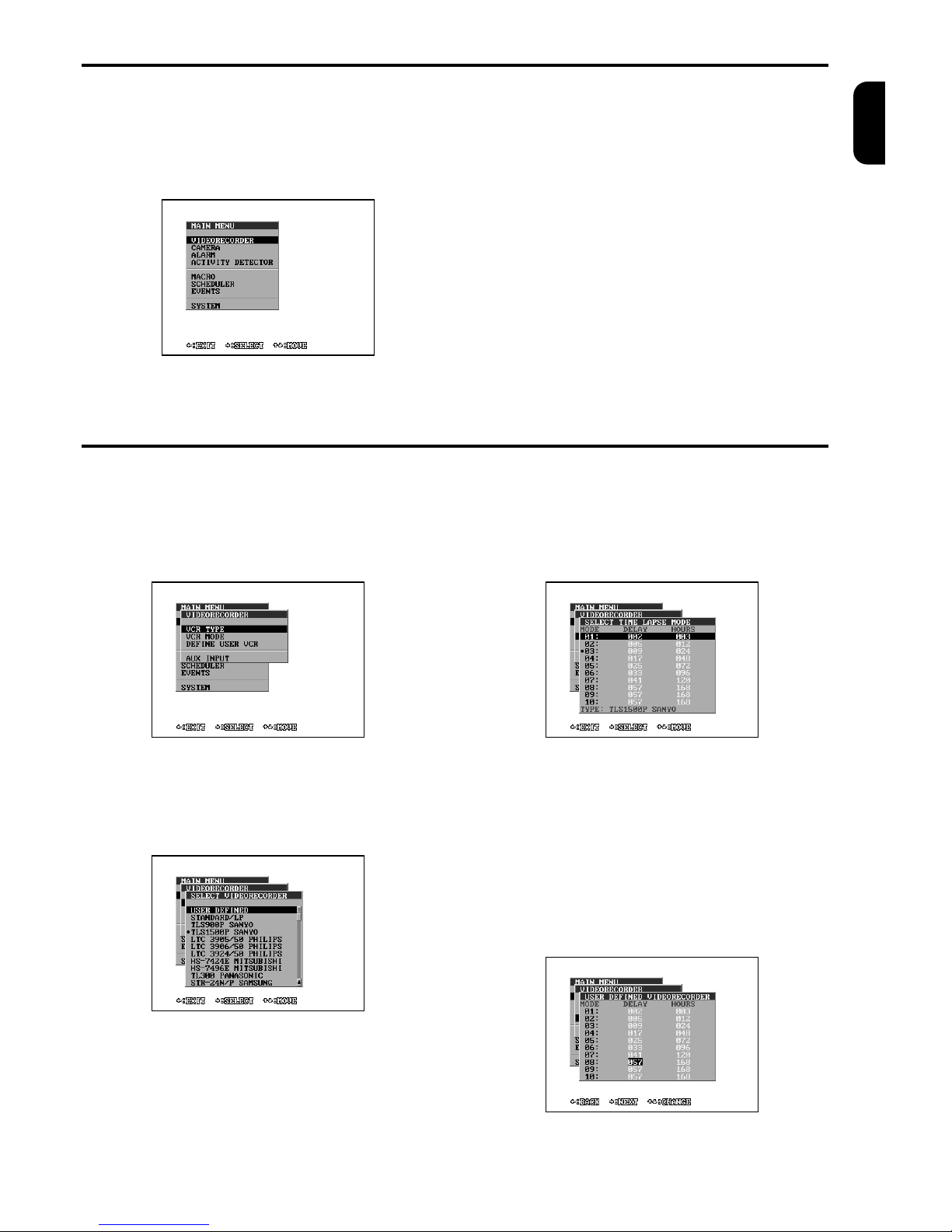
By pressing the button MENU the main menu is displayed on the screen. It is the starting point for setting
up all multiplexer functions. To make the work easier,
there is an info line at the bottom of the screen.
MAIN MENU
MENU CONTROLLING
- The button ¬ (BACK) cancels the actual level of the
menu on the screen and goes back to the previous
level.
- The buttons - and ¯ enable moving up and down or
correct the edited level.
- The button ® (CHOOSE, NEXT) chooses a sub-
ordinate menu or moves to the other level.
- The buttons of 1 to 10 set up a number.
- The button ZOOM+ delete last figure in the number
- The button ZOOM- enters number.
- For faster move into the subordinate menu it is pos-
sible to enter the number of its line. You can get directly into the menu, which you want to change using several buttons.
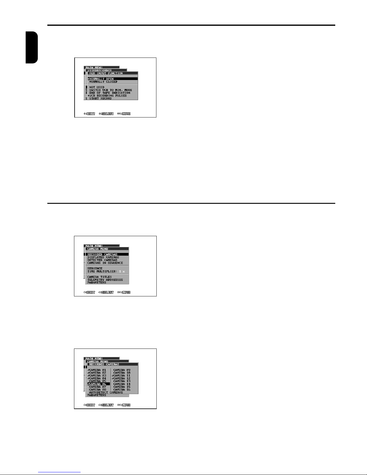
MENU - VIDEORECORDER
Set up the type and working modes of the VCR in this
menu. For the correct recording function it is important
to ensure that the VCR and multiplexer work in the
same mode. You can also define the type of the connection between the VCR and the multiplexer with the
help of AUX input.
VCR TYPE
Set up your VCR type here. If your VCR type is not
mentioned here, use an analogous type or choose a
user defined VCR and set up the working VCR modes
in the menu User defined VCR (see page 7).
VCR MODE
Time-lapse VCRs can work in several working modes.
You can set the topical working mode of the VCR by
the choice of the line of 1 to 10. The working mode of
the VCR can also be set up with the help of macro or
AUX input on the alarm connector (see page 8).
USER DEFINED VCR
Time-lapse VCRs do not have only common recording
speed in real time (50 or 60 fields per second), but
also extended modes. These modes extend the recording time from 3 hours (using the E180 cassette) to
12, 24, 48, 72, 96, 120, 168, 240, 480 or 960 hours.
These recording times are different at various types of
VCRs. This longer recording time is attainable by
omitting some fields during recording. The parameter
DELAY sets up intervals between recorded fields in
this menu.
Page 10
MENU – VIDEORECORDER (continued)
8 TP4MD/CD / TP10MD/CD / TP16MD/CD
ENGLISH
AUX INPUT
AUX input is used for delivering information from the
VCR to the multiplexer. Set up the required function.
Normally open / closed – specify AUX input activity
in an inactive state
Not used – the AUX input is not used
Switch VCR to the minimal mode – the VCR informs
the multiplexer that under the influence of some situation (for example alarm condition) it records in the
highest speed (in the real time mode). Multiplexer
must adapt itself to the VCR speed.
End of tape indication – the VCR informs that a tape
is at the end. The multiplexer displays the note about
this situation for the operator on the screen.
VCR recording pulses – it is the function of recording
mode synchronised from the VCR. Some VCRs have
a signal with recording pulses (normally marked as
SW OUT or CLK OUT) leaded on the back panel,
which determines the VCR recording speed. This
signal can be used for the synchronisation of recording between the VCR and the multiplexer. If the
operator switches the recording speed on the VCR or
the recording speed is changed by the influence of the
alarm signal on the VCR, the multiplexer changes its
recording speed automatically.
Start record – if the AUX input activity is detected,
multiplexer starts the recording automatically.
MENU - CAMERA
Set up camera parameters of recording, displaying,
activity detection, sequential switching and telemetry
in this menu.
RECORDED CAMERAS
By marking the lines choose the cameras, which will
be recorded to the VCR after the recording is switched
on. If you choose the line Autodetect cameras, the
multiplexer finds out, which cameras are in operation
at the moment and marks them in the table.
DISPLAYED CAMERAS
By marking the lines choose the cameras, which will
be displayed during the live mode (LIVE) even in the
automatic switching sequence or during playback
(PLAY).
DETECTED CAMERAS
By marking the lines choose the cameras, which will
have the activity detection in operation, see Activity
detection on page 12.
CAMERAS IN SEQUENCE
By marking the lines choose the cameras, which will
be available for the automatic switching sequence on
the spot analogue output (MON SPOT).
Page 11
MENU - CAMERA (continued)
TP4MD/CD / TP10MD/CD / TP16MD/CD 9
ENGLISH
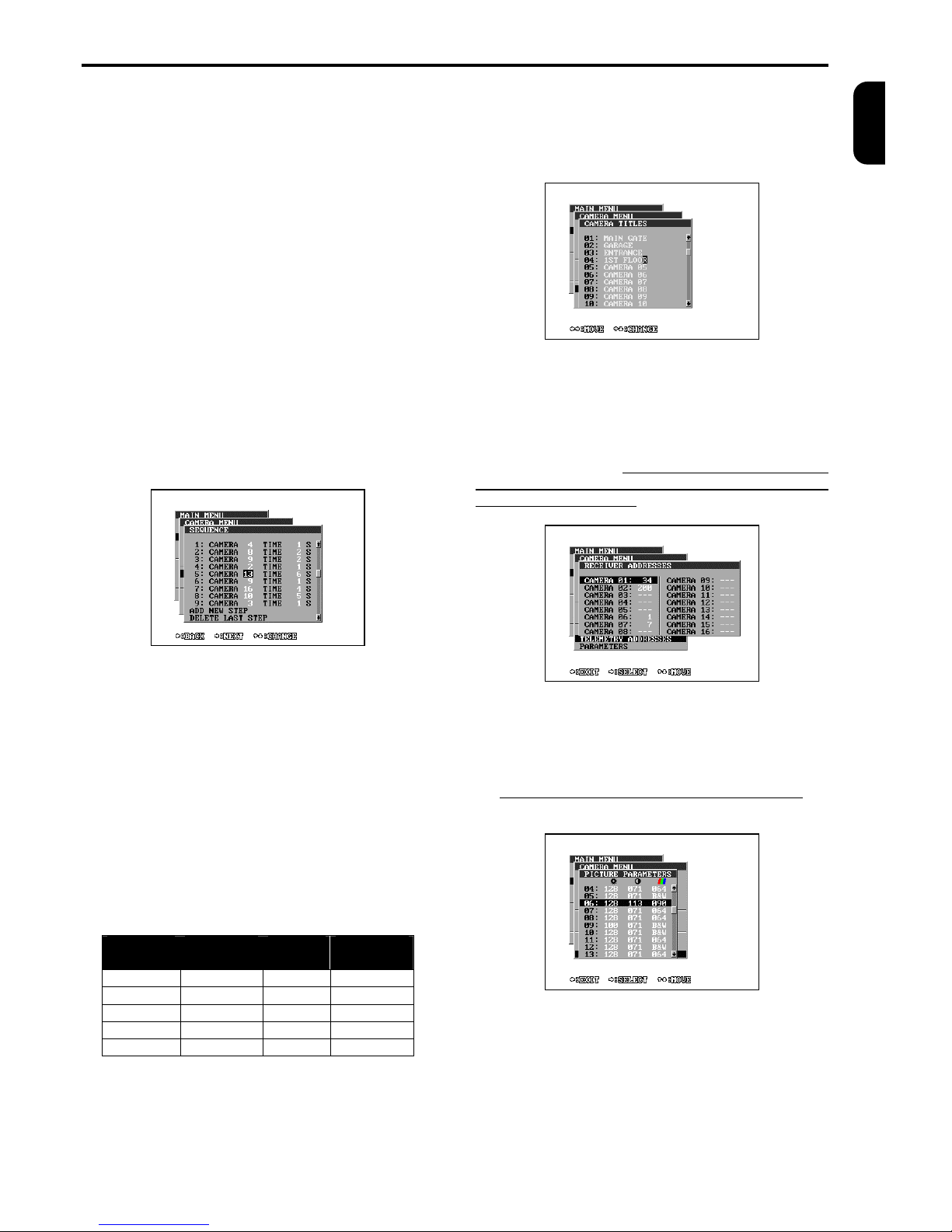
SEQUENCE
The menu SEQUENCE programmes the order and
time of the displaying (switching) of particular cameras
on analogue switching output (MON SPOT) or in LIVE
mode on main monitor. You can program from 2 up to
32 switching steps of the sequence. The individual
steps are marked with sequential numbers and are
arranged one under the other. If you want to choose
the camera or time of some step, you have to choose
the particular step with the help of direction keys up
and down at first. Then press the button ®
(CHOOSE) and now you can change the camera
number with the help of arrow keys. By another pressing the button (NEXT) you can go to edit the time. The
time of this step can be set up in the interval from 1 up
to 255 seconds. The next press of the button ® finishes the editing of the chosen step. The last two
steps of the menu obtain the functions for the change
of the sequence length: adding a new step (ADD
NEW STEP) and deleting the last sequence step
(DELETE LAST STEP). By pressing the button ¬
(END) you can stop the editing of the sequence and
return to the camera menu.
TIME MULTIPLIER
If you would like to change the camera switching time,
it is not always necessary to reprogram the switching
sequence. All the time data of the sequence are multiplied with the parameter TIME MULTIPLIER. The
time of the displaying of particular cameras can be
quite lengthened or shortened and the proportion of
displaying particular steps (cameras) still lasts. It is
important to note that the time of displaying one step
after the change will still stay in interval of 1 to 255
seconds.
There is an illustrated example in the table, how the
switching time changes according to the programmed
switching sequence “Sequence time”, if you use the
time multiplier 8× or 1/4×.
CAMERA TITLES
Each camera can have its own title for better identification. The title can include up to 16 symbols and
there can be used letters from A to Z, numerals from
0 to 9, symbols . , : ! ? ‘ + - * / ( ) < > = and a space.
TELEMETRY ADDRESSES
The address of the telemetry receiver can be defined
in the interval from 0 up to 255 for controlling the
PAN/TILT camera heads and lenses for each camera.
The multiplexer, with the help of this address, distinguishes particular devices, which are connected to the
RS 485 or CAN bus. If a camera does not have the
receiver address set up, you can not switch on the
telemetry for the camera.
PICTURE PARAMETERS
Colour multiplexers enable setting of picture parameters for every camera. Implicit values are: 110 for
brightness, 64 for contrast, and 64 for colour. You are
not allowed to set colours if using B&W multiplexers.Using a B&W camera set colour to “B&W”. The
camera displaying will be sped up.
Camera Time of
sequence
Multiple
8 ×
Multiple
1/4
2 1 s 8 s 1 s
4 12 s 96 s 3 s
8 100 s 255 s 25 s
3 4 s 32 s 1 s
5 24 s 192 s 6 s
Page 12
MENU – ALARM
10 TP4MD/CD / TP10MD/CD / TP16MD/CD
ENGLISH
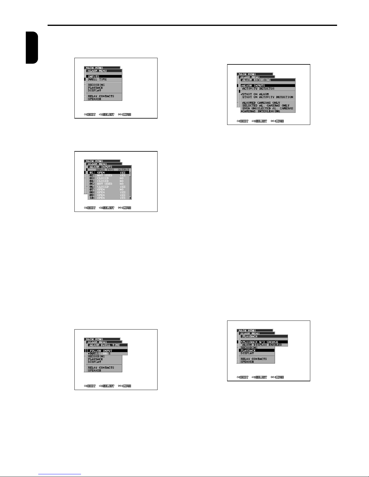
The alarm outputs and inputs characteristics, the reactions to alarm, the activity detection or the video
signal lost are set up in this menu.
ALARM INPUTS
You can set up the activity of the any alarm input and
its influence to the alarm output (relay).
INPUT TYPE
Not used - signal is ignored on this output
Closed - input is normally closed (active if open)
Open - input is normally open (active if closed)
OUTPUT
Yes - alarm input influences the alarm output (relay)
No - alarm input does not influence the alarm output
(relay)
DWELL TIME
The length of alarm reaction to the impulse on the
alarm input can be set up from 1 up to 99 seconds
there. If you set up the function FOLLOW INPUT,
alarm will be active during the time of lasting the alarm
signal on the alarm input.
RECORDING
The recording to VCR can be modified, if the alarm is
detected. For setting up the changes the following
menu is used:
Alarm inputs - marking the line, the alarm inputs will
influence recording.
Activity detector - if you mark this line, the activity
detector will influence recording.
Alarmed cameras only - only the cameras with the
alarm detection will be recorded during the alarm lasting. The source of the alarm can be either from the
alarm inputs or from the activity detector.
Selected alarmed cameras only - only the cameras
with the alarm detection, which are also selected for
recording, will be recorded during the alarm condition
(see the menu Recorded cameras on page 13).
Even unselected alarmed cameras - all cameras will
be recorded during the alarm condition, either the
ones with the alarm detection or the ones chosen for
recording.
Cameras interleaving – the cameras with the alarm
detection will be interleaved into the normally recorded cameras.
For example: Cameras 1, 2, 3, 4 are chosen for recording and the alarm is detected on the cameras 6
and 7. The recording sequence will be as following:
1, 6, 7, 2, 6, 7, 3, 6, 7, 4, 6, 7, 1, 6, 7 etc
PLAYBACK
You can choose, whether the alarm signals and activity detection will influence the displaying during the
playback or not.
Page 13
MENU - ALARM (continued)
TP4MD/CD / TP10MD/CD / TP16MD/CD 11
ENGLISH
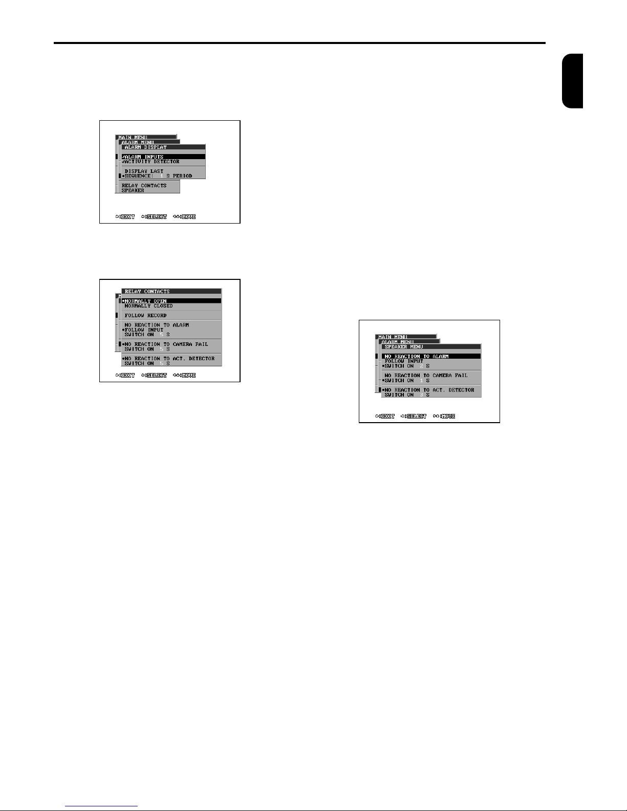
DISPLAY
When the alarm is detected, the camera with the last
activated alarm can be switched into the full screen
mode or the alarm cameras on the main or spot channel can cycle according to the prepared period.
RELAY CONTACTS
Controlling an alarm output is displayed in the following menu.
Normally open/closed – this function defines the
situation of the relay without alarm.
Follow record – if this function is selected, the relay
is active during the recording, functions below than
have no meaning.
No reaction to alarm – no reaction to alarm inputs.
Follow input – active during the alarm lasting on any
of the inputs.
Switch on XX seconds – active for the time from 1 to
99 seconds since the last alarm activation.
No reaction to camera fail – no reaction to the video
signal lost.
Switch on XX seconds – active for the time from 1 to
99 seconds since the camera signal fails.
No reaction to activity detector – activity detector
does not influence alarm output.
Switch on XX seconds – active for the time from 1 to
99 seconds since the last activity detection.
SPEAKER
This menu controls the acoustic signalling of alarm.
Meaning of corresponding lines is the same as in
menu Relay contacts (see page 11).
Page 14
MENU – ACTIVITY DETECTOR
12 TP4MD/CD / TP10MD/CD / TP16MD/CD
ENGLISH
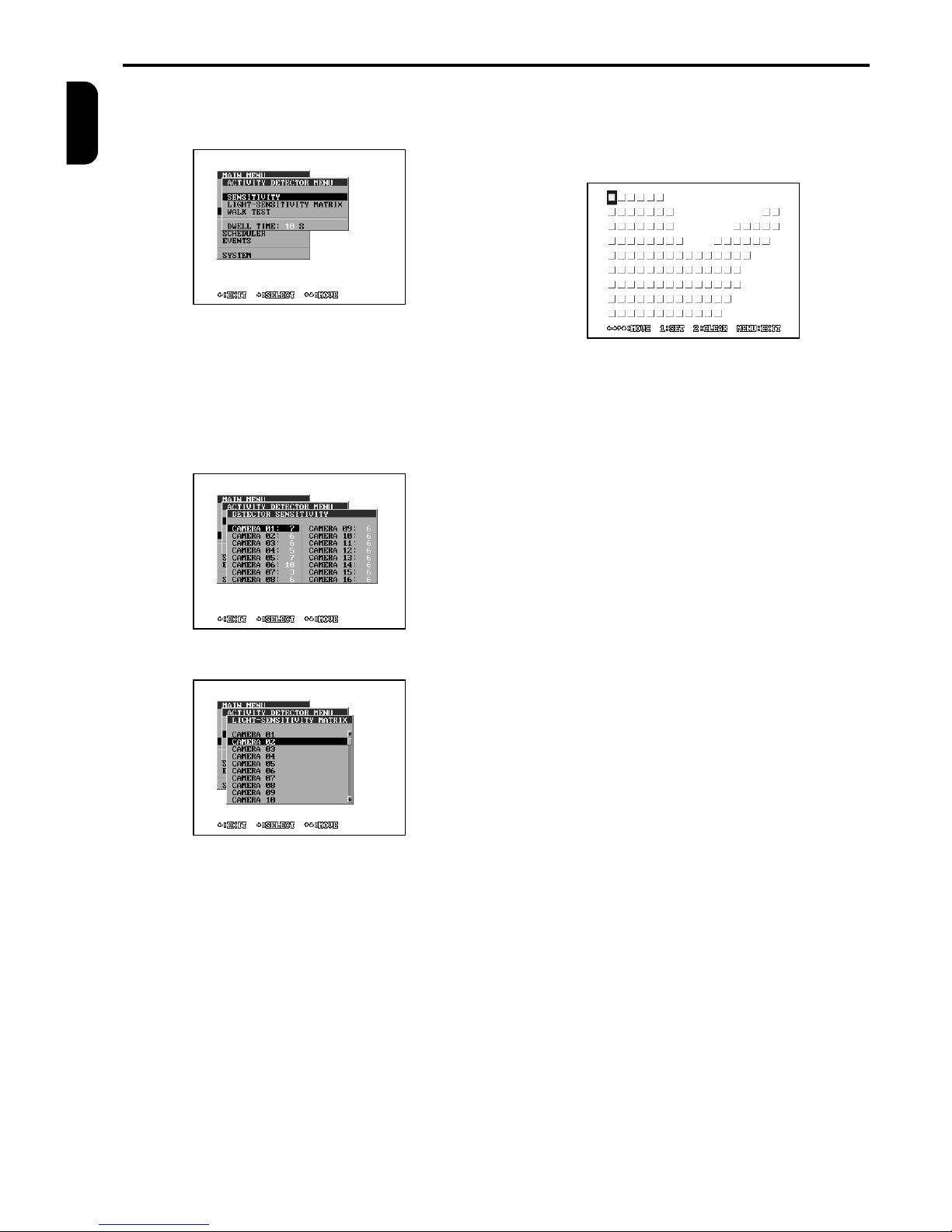
Multiplexers TP have the activity detector, which enables to detect the motion in the images of connected
cameras and can influence multiplexer activities.
SENSITIVITY
The level of sensitivity can be set up for each camera
in this menu. It controls how sensitively the cameras
should react to the image changes. The levels can be
set up in the interval from 1 to 10. The lower values
(lower sensitivity) are suitable for outdoor cameras
with the wide range of lighting changes and the higher
sensitivity for indoor cameras with constant lighting.
LIGHT-SENSITIVITY MATRIX
The area, in which the activity detector will explore the
image changes, can be defined with the help of this
matrix 18 x 9 of light-sensitivity elements for every
camera. The transparent squares represent active
fields.
There are described controlling buttons for editing the
light-sensitivity matrix here:
1 – sets one active matrix field
2 – clears one field
3 – sets the whole line
4 – clears the whole line
WALK TEST
The walk test is used for checking the correct setting
of the activity detector and continuously displays the
detected areas together with the picture.
DWELL TIME
It is the time of multiplexer reaction after the motion
detection. This time is used especially for the reason
of some overlapping of recording at the VCR after the
moment of detection. If the dwell time is for example
30 seconds, the multiplexer will react (record or display this camera) even 30 seconds after the motion
detection.
Page 15
MENU – MACRO
TP4MD/CD / TP10MD/CD / TP16MD/CD 13
ENGLISH
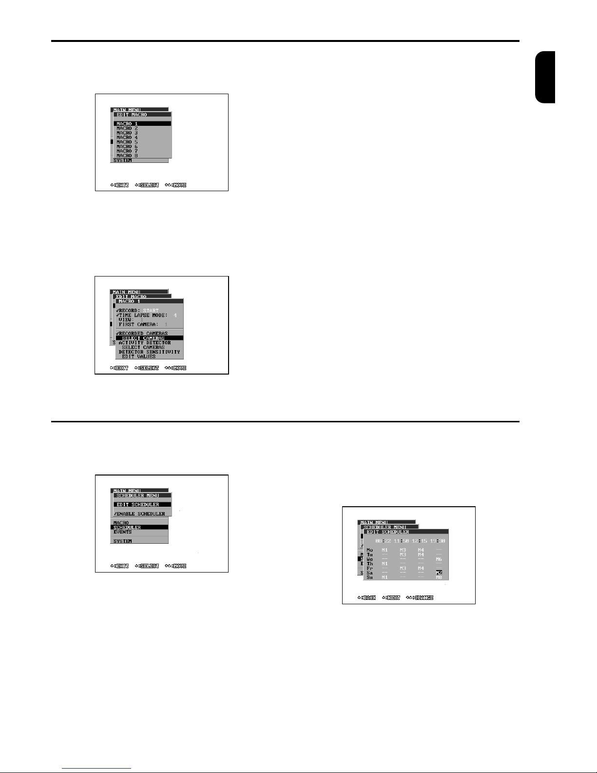
You can edit the macros in this menu. Macro is a set
of parameters, which change the multiplexer settings
when the macro is launched.
MACRO 1 TO 8
Every macro enables to change all or some of the
following multiplexer’s characteristics. If the line is
marked, the parameter will be changed to the defined
value after the macro is been launched. If this item is
not marked, the parameter remains unchanged.
Record – determines, whether to start or stop the
recording to the VCR
Time-lapse mode – determines, whether or which
mode of the recording to the VCR will be set up after
the macro is launched
View – the number of displayed view.
First camera – the number of first displayed camera
in the view
Recorded cameras – by marking this line, the set of
recorded cameras will be changed after the macro is
launched
Select cameras – by opening this submenu you can
choose your own set of the cameras for recording.
Activity detector – by marking this line, the cameras
for activity detection will be changed after the macro is
launched
Select cameras – your own set of the cameras for
activity detection
Sensitivity of the detector – by marking this line, the
sensitivity will be changed after the macro is launched
Edit levels – edits the sensitivity levels
MENU - SCHEDULER
The multiplexer scheduler enables the automatic starting of a macro at the certain time of a certain day of
the week.
EDIT SCHEDULER
You can edit 4 time memories, by which you want to
change the multiplexer setting. The macro, being set
up in the menu, starts every day in a week at this
time. For example, the following menu shows that on
Friday at 11:50, the macro number 3 is launched.
ENABLE SCHEDULER
If you mark this line, the scheduler is put in operation
and launches the programmed macros.
Page 16
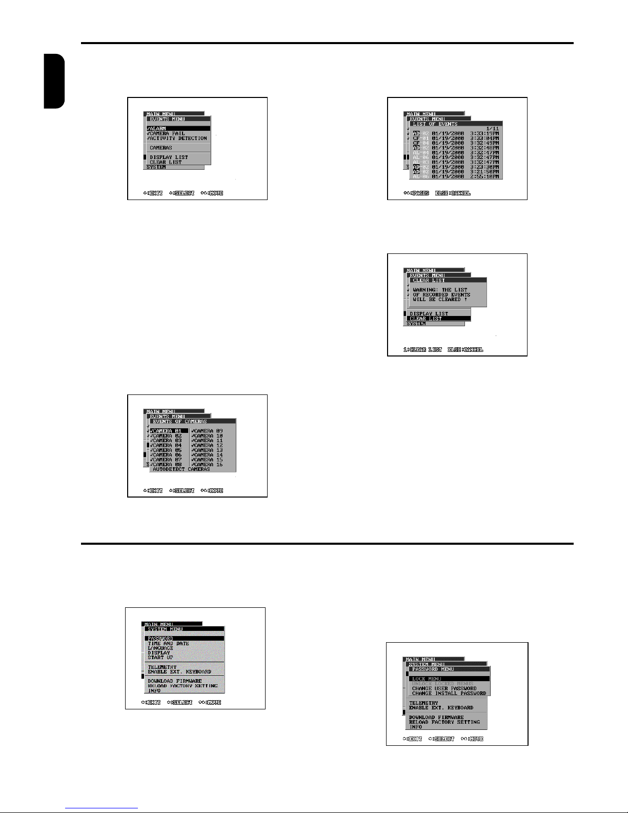
MENU – EVENTS
14 TP4MD/CD / TP10MD/CD / TP16MD/CD
ENGLISH
Multiplexers TP enable storing of alarm events into its
own memory. Using this menu you are able to choose
what events will be recorded and displayed in the list.
ALARM
If the item is marked, the alarms will be recorded and
displayed in the list of events.
CAMERA FAIL
If the item is marked, the camera fails will be recorded
and displayed in the list of events.
ACTIVITY DETECTION
If the item is marked, the cameras with activity detection will be recorded and displayed in the list of
events.
CAMERA EVENTS
The cameras, which will be recorded and displayed
into the list of events, are chosen in this menu.
DISPLAY LIST
You can display the list of events, which corresponds
to previous setting in this menu.
CLEAR LIST
You can clear the list of events in this menu by pressing the button 1.
MENU - SYSTEM
In this menu you can set up such parameters, which
correspond to the functions of multiplexers as the
password, the data and time setting, interlace correction, telemetry characteristics and the language
choice.
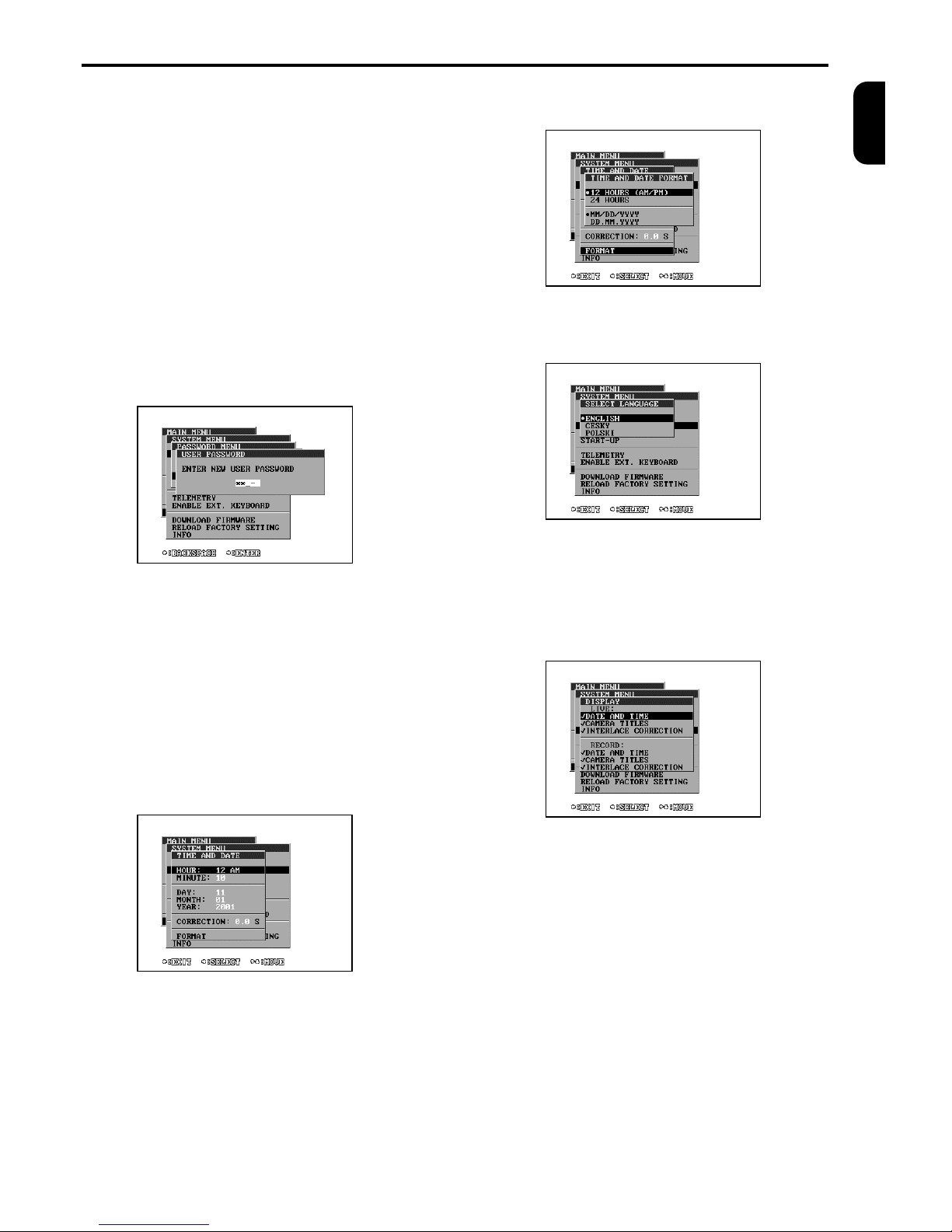
PASSWORD
The user can control the access into the menu of TP
multiplexers by user and install passwords. The use
password enables the entrance to the user functions.
The install password – enables the entrance to the
user and install functions. The install password is
used also as the insurance against the forgetting of
the user password. If the user menu is cancelled or
was already set up, the menu is available without
another password setting. If the install password in
cancelled, the user has free access into all menus.
Page 17
MENU – SYSTEM (continued)
TP4MD/CD / TP10MD/CD / TP16MD/CD 15
ENGLISH
Lock menu – using this function, menu is locked. If
the user password was set up, the system will ask you
for setting up the entrance password during another
try of access. If the install password was set up, this
choice will lock all install menus. To unlock them it is
possible only with the help of the function Unlock
locked menus. The item Lock menu is not available in
the case that no password has been set up or the
menu has been already locked.
Unlock locked menus – after choosing this item and
setting the correct install password, the install menus
will be unlocked. This choice is blocked, if the install
password has been disabled or the menus are
unlocked already.
Change user password – enables to set up a new or
disabled the old user password. Setting an empty
password disables the password.
Change install password – enables to set a new or
disable the old install password. Setting an empty
password disables the password. If the menu is not
available, it is necessary to unlock the menu in the
menu Unlock locked menus by typing the install
password.
TIME AND DATE
This menu enables the possibility of changing the
topical time and date of the multiplexer and its format
of displaying on the monitor. If you choose some time
and date item, time will stop and will not start since
this menu is finished.
TIME CORRECTION
You can correct the multiplexer internal clock deviations by setting the value of seconds added or taken
off per a day. For example: If the clock of multiplexers
delays 2.5 seconds a day, increase the value of the
correction of 2.5 s, if it speeds up decrease of 2.5 s.
FORMAT
Choose the displaying format of time and date on the
screen.
LANGUAGE
Choose the language for communication with user.
DISPLAY
Choose whether to display camera titles and the date
and time on the status line in LIVE mode and recording. Then you can set-up the interlace correction.
The interlace correction influences the displaying of
the cameras on the monitor and the recording.
Disabled interlace correction of live images can cause
the gliding effect of reduced-size pictures, which is
caused by the displaying of different fields of the same
camera. The same field will be displayed by marking
this item. The picture stability increases with result of
slower displaying.
The interlace correction of record always ensures the
recording of same fields of the camera. The playback
quality will be higher, but it can result the lower frequency of recorded cameras switching. This choice
will affect only the recording to the VCR in the minimal
mode (3 hours).
Page 18
MENU – SYSTEM (continued)
16 TP4MD/CD / TP10MD/CD / TP16MD/CD
ENGLISH
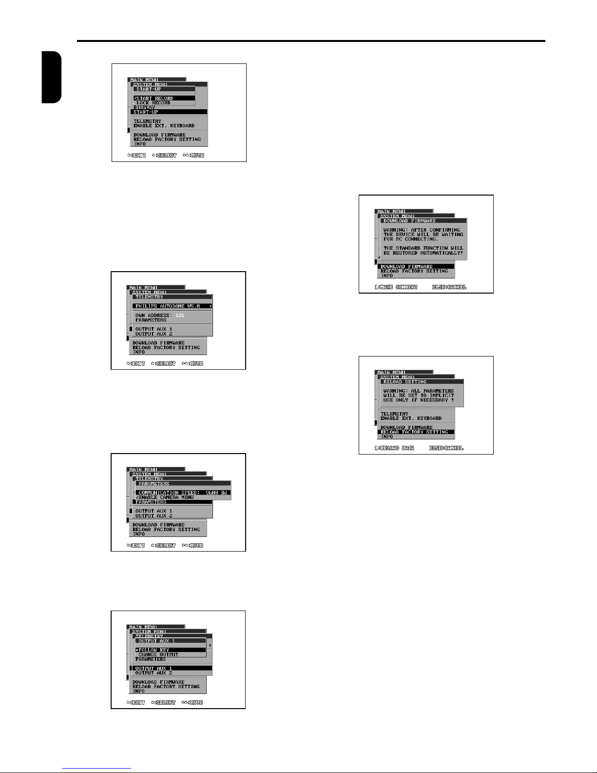
START - UP
The device starts automatically recording after the
device is turned on, if the START RECORD line is
marked.
If the LOCK RECORD line is marked, the possibility of
switching recording off from the keyboard is blocked.
TELEMETRY
The telemetry receiver parameters of the multiplexer
can be set up in this menu.
Select protocol – first line selects the communication
protocol.
Own address – every device on the telemetry bus
must have its address, different from other connected
devices. The multiplexer address can be set up here.
Parameters –setup parameters for selected protocol.
The following menus control the function of user outputs AUX1, AUX2 (see Telemetry controlling on
page 8)
Change output – by pressing one of the buttons
AUX1/2 the state of user output will be changed.
Follow key – The user output is switched on while
holding the button AUX.
ENABLE EXTERNAL KEYBOARD – marking this
line you enable multiplexer to be controlled from external keyboard.
DOWNLOAD FIRMWARE
After choosing and confirming, the unit will be waiting
for firmware downloading from PC. On the PC the
downloading program must be started.
RELOAD FACTORY SETTING
If you press the button 1, all parameters will be
changed into the factory setting.
INFO
The system information of multiplexer is shown here.
Page 19
BEFORE LOOKING FOR HELP
TP4MD/CD / TP10MD/CD / TP16MD/CD 17
ENGLISH
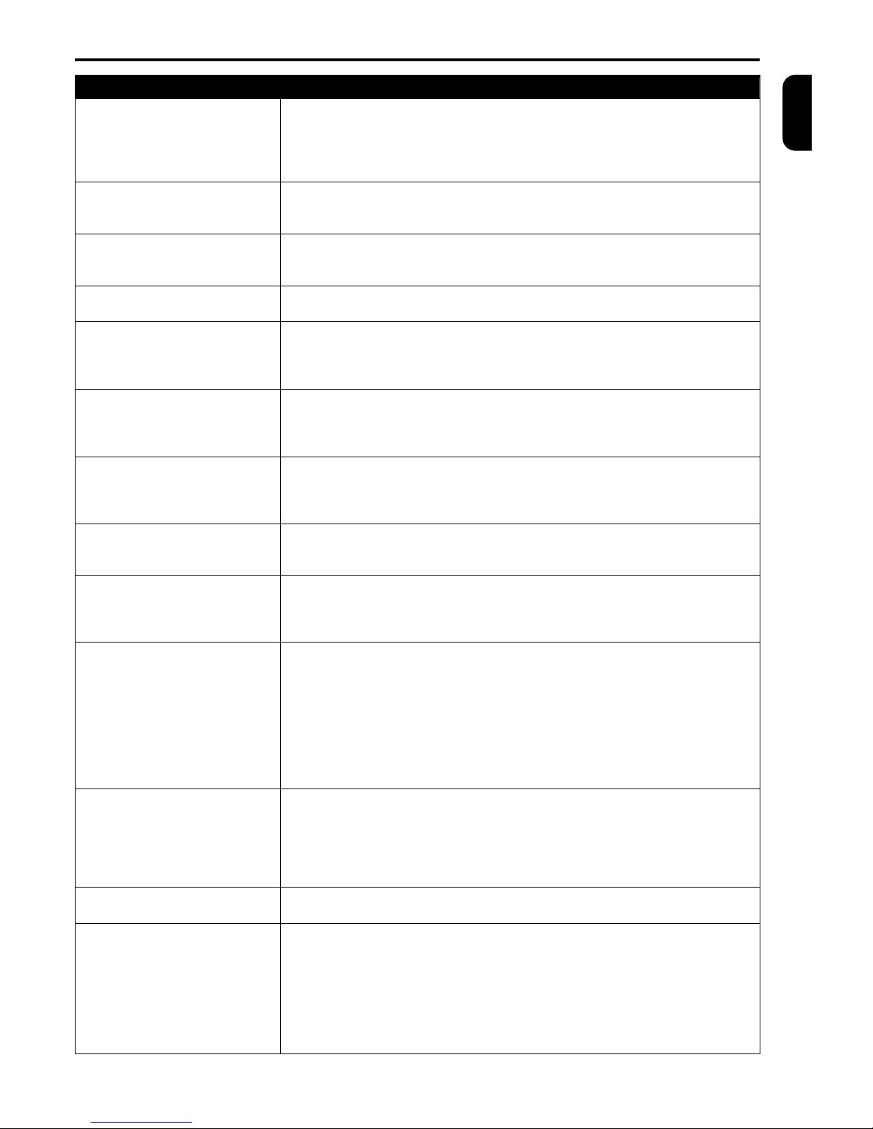
YOUR TROUBLE THE CAUSE AND ITS SOLUTION
After switching on the device
does not work.
· The power supply is not connected.
o Check the power supply connector and the power supply polarity.
· The supply adapter is not dimensioned sufficiently.
o Check if the adapter power output and voltage corresponds to the multiplexer
requirements (12V, min 700mA).
After connecting the supply
voltage some LEDs are on,
but the device does not work.
· The power supply adapter is not dimensioned sufficiently.
o Check if the adapter power output and voltage corresponds to the multiplexer
requirements (12V, min 700mA).
Horizontal stripes go over the
divided screen.
· The power supply adapter is not dimensioned sufficiently.
o Check if the adapter power output and voltage corresponds to the multiplexer
requirements (12V, min 700mA).
There is no picture on the
monitor.
· The cable to the monitor is defective.
o Check the connecting cable to the monitor carefully.
Some cameras are not
displayed and cannot be
detected with auto detection.
· The camera signal is not connected properly or has been debased by strong
interference from the power distribution.
o Check the camera patch cord. Check the camera and monitor ground con-
ductor and the interference level in the signal.
The picture on the split screen
has stopped.
· The picture has been stopped from the keyboard (HOLD key is blinking).
o Press the button HOLD
· The cameras were disconnected or switched off.
o Check the camera power supply and connection.
Some cameras on divided
screen are flashing.
· Video inputs are terminated improperly.
o Check connection on back panel. Every output video signal must be loaded
with one 75 Ω termination at the end of the line by the connected device or
must be left unconnected.
Cameras on divided screen
are slightly shaking.
· Interlace correction is switched off.
o Set up the interlace correction of live picture in menu SYSTEM - DISPLAY
(page 16). The shaking stops with result of slower displaying.
At colour multiplexer
displayed have incorrect
colours.
· Improper setting of camera parameters.
o Check the brightness, contrast and colours setting in menu CAMERA -
PARAMETERS (page 9). Black and white cameras mark as “B&W” in colour
column.
The playback from the VCR
does not work.
· Missing or defective signal from VCR.
o Check the signal quality from VCR with connection the VCR output directly to
the monitor. The signal quality can be affected with VCR adjusting (V-Sync,
Tracking).
· Cameras are not switched for displaying.
o Set the cameras in menu DISPLAYED CAMERAS (page 8).
· Cameras were not recorded to VCR.
o Check the setting of cameras in menu RECORDED CAMERAS (page 8).
Check the connection cables to the VCR. Check the VCR for recording.
The sequential output does
not switch cameras
automatically.
· Automatic sequence is switched off manually.
o Switch to sequence controlling (SEQ) and switch on the automatic sequence
(AUTO).
· Sequence or switching time is set up incorrectly.
o Check the setting of the sequence in menu SEQUENCE, CAMERAS IN
SEQUENCE, TIME MULTIPLIER (pages 8 and 9).
At simplex multiplexer it is not
possible to enter menu.
· The recording is running.
o Switch off the recording using REC button and enter the menu.
The recording starts by itself.
· Start of recording is set up on alarm or activity detection.
o Check start of recording in menu ALARM - RECORDING (page 10). Check
alarm inputs and activity detector.
· Start of recording is set up on AUX input.
o Check the setting of AUX input in menu VIDEORECORDER - AUX INPUT
(page 8).
· Recording was started with macro from the scheduler.
o Check menu SCHEDULER and MACRO (page 13).
Page 20

BEFORE LOOKING FOR HELP (continued)
18 TP4MD/CD / TP10MD/CD / TP16MD/CD
ENGLISH
YOUR TROUBLE THE CAUSE AND ITS SOLUTION
Camera cannot be controlled
with the RS 485 or the CAN
bus (rotating and zoom lens
controlling).
· Camera is not at the first position in view.
o Press the corresponding camera number first before controlling.
· Camera does not have set up the telemetry address of receiver (multiplexer
does not beep when direction arrows are pressed).
o Set up correct receiver address of corresponding camera in menu CAMERA
- TELEMETRY ADDRESSES (page 9).
· Camera has set up incorrect receiver address.
o Set up correct receiver address of corresponding camera in menu CAMERA
- TELEMETRY ADDRESSES (page 9).
· The connection with telemetry receiver is defective.
o Check the connection of multiplexer and receiver on bus (page 4).
Multiplexer cannot be
controlled from external
keyboard.
· Multiplexer is blocked due the control from other keyboard (5 seconds since
the last command - signalled with long beep).
o Wait and try to control later.
· Different telemetry address of controlled device on external keyboard and
multiplexer.
o Check the device address of multiplexer in menu SYSTEM - TELEMETRY
(page 16) and address of controlled device on external keyboard.
· The connection between multiplexer and external keyboard is defective.
o Check the connection of multiplexer and keyboard on CAN bus (page 4).
The device does not react to
alarm inputs.
· The alarm processing is switched off in the main menu.
o Set up the alarm function in menu ALARM (page 10 and 11).
· The connection of the alarm inputs is defective.
o Check the connection of the alarm inputs (page 3).
The device reacts to alarm
inputs incorrectly.
· The set up of alarm inputs polarity is incorrect.
o Check the polarity of alarm inputs in menu ALARM - INPUTS (page 10).
The alarm output (relay) does
not react properly.
· The polarity of alarm is set up incorrectly.
o Set up the normal state of alarm output in menu RELAY CONTACTS
(page 11).
· The reaction to required condition is switched off.
o Set up reaction to alarm inputs, activity detection or camera fail in menu
RELAY CONTACTS (page 11). Check the reaction of individual alarm inputs
to alarm output in menu ALARM - INPUTS (page 10).
Note: If you want the alarm output to switch to ground (e.g. for VCR controlling), connect one of the relay contacts to ground.
The device does not react to
the motion in the camera
picture.
· The activity detection for corresponding camera is switched off.
o Check the menu DETECTED CAMERAS (page 8).
· The sensitivity or the light-sensitivity matrix is not set up correctly.
o Check the setting in menu SENSITIVITY and LIGHT-SENSITIVITY MATRIX
and try the WALK TEST (page 12).
· The reaction to the activity detection is switched off.
o In menu ALARM check the menu RECORDING, DISPLAY, RELAY
CONTACTS and SPEAKER (pages 10 and 11).
Multiplexer internal clock is
delaying or speeding up.
· The time correction is not set up.
o Find of what time is the clock delaying or speeding up per one day and of this
value increase or decrease the time correction in menu TIME AND DATE CORRECTION (page 15).
All LEDs are flashing.
· Firmware fault detected (probably caused by previous incomplete firmware
downloading).
o Download firmware. Connect device with PC by RS 232 and start the pro-
gram for firmware downloading on the PC.
Page 21
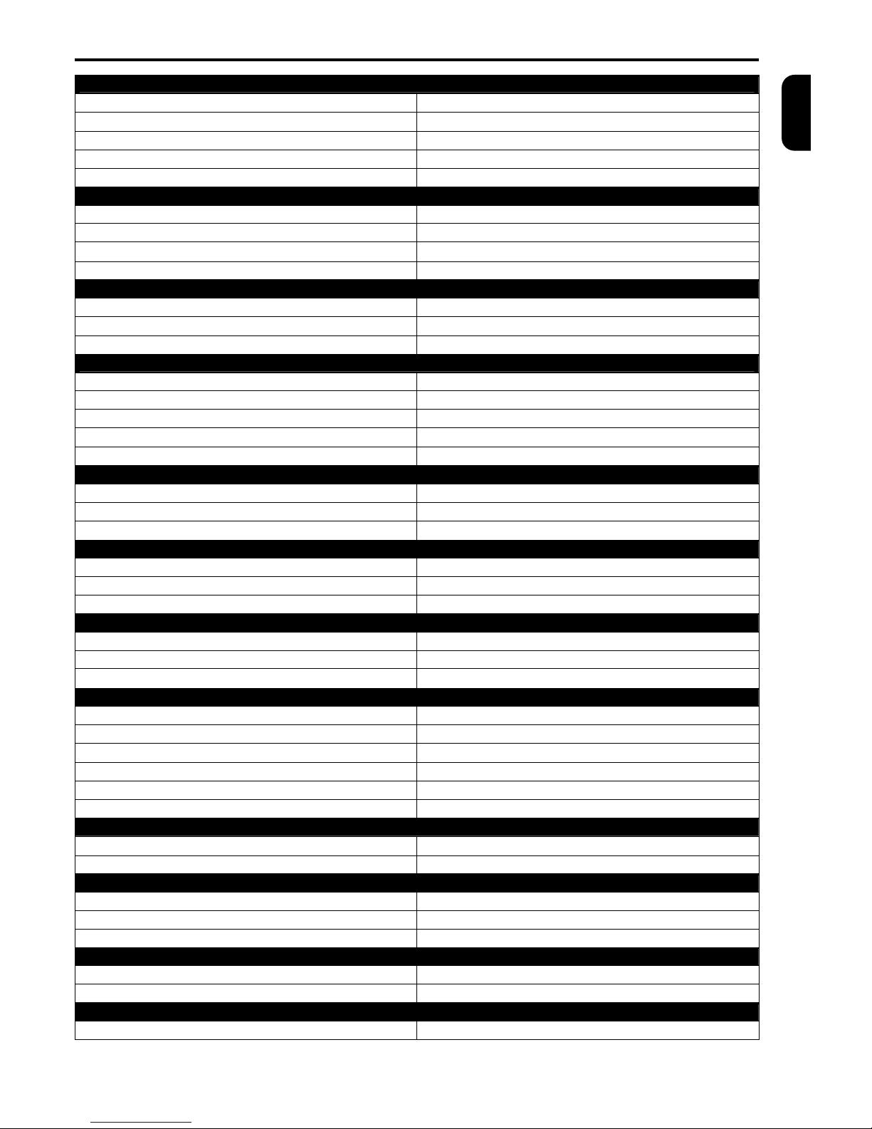
TECHNICAL SPECIFICATION
TP4MD/CD / TP10MD/CD / TP16MD/CD 19
ENGLISH
PICTURE PARAMETERS
TV standard:
PAL (CCIR) / NTSC (EIA)
Number of the active TV lines:
576 / 480
Samples per TV line:
864 / 856
Grey scale (black and white multiplexers):
256
Number of colours (colour multiplexers):
16 million
VIDEO INPUTS
Number:
4+1, 10+1 or 16+1 (composite)
Amplitude:
0,75 - 1,5V p-p
Input impedance:
75 W (high if a connector is plugged in to video output)
Connectors:
BNC (composite)
VIDEO OUTPUTS
Number:
3 independent (composite), 1 independent (S-VIDEO)
Standard:
1 V p-p load of 75 W
Connectors:
BNC (composite), MINI DIN 4 (S-VIDEO)
ALARM INPUTS
Number:
4, 10 or 16
Loop connection:
input – ground (GND)
Activity:
programmable
Maximum alarm loop impedance:
1 kW
Connector:
D-SUB 37-pin female connector
AUX INPUT
Loop connection:
input – ground (GND)
Activity:
programmable
Maximum alarm loop impedance:
1 kW
ALARM OUTPUT
Number:
1 potentialless (contacts of low voltage relay)
Maximum switching voltage:
40 V
Maximum switching current:
0.5 A
RS 485 INTERFACE
Baud rate:
depend on protocol
Maximum length:
1000 m
Terminators:
120 W at both ends
CAN INTERFACE
Baud rate:
50 kBs
Maximum length: bus/ stubs/ cumulative stubs
1000 m / 60 m / 300 m
Terminators:
120 W at both ends
Cable for bus length 0 – 40 m:
0.25mm2 - 0.34mm2 (AWG23, AWG22)
Cable for bus length 40 – 600 m:
0.34mm2 - 0.6mm2 (AWG20)
Cable for bus length 600 – 1000 m:
0.75mm2 - 0.8mm2 (AWG18)
TEMPERATURE CONDITIONS
Range of operating temperatures:
0 – 40 °C
Humidity:
max. 85 %
POWER SUPPLY
Input voltage:
12 VDC
Power consumption:
max. 7 W
Connector:
concentric 5.5 × 2.1 mm
MECHANICAL PARAMETERS
Dimensions:
436(W) × 44.5(H) × 230(D) mm
Weight:
3,3 kg
ACCESSORIES
Alarm connector D-SUB male + cover:
1 piece
 Loading...