

Page 1
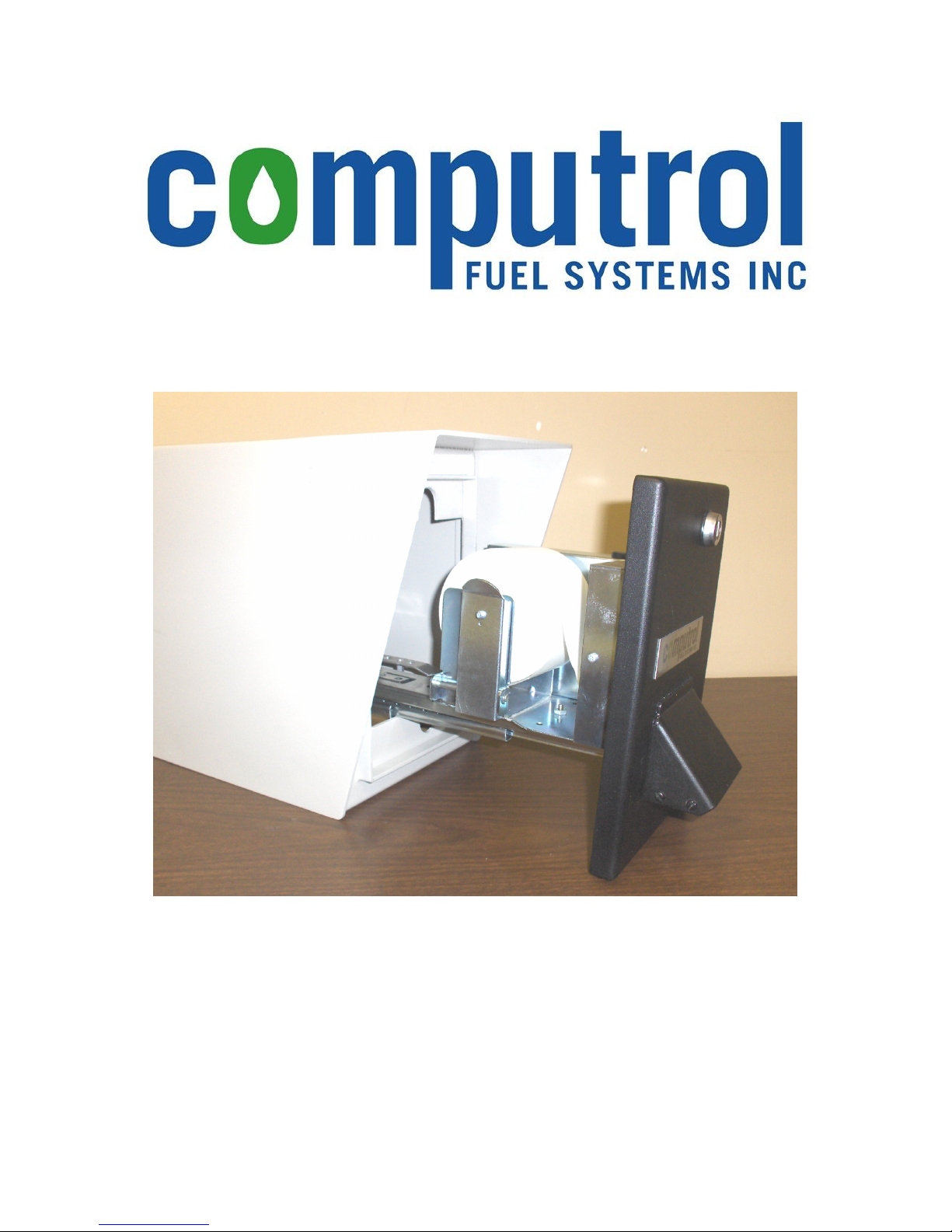
RP6000 Receipt Printer
Document PN 99-515
Installation & Operation
Manual
© 2008 Computrol Fuel Systems Inc.
All rights reserved.
Page 2

RP6000 Receipt Printer
Installation & Operation Manual
Congratulations on your purchase of a Computrol RP6000 Receipt Printer (PN 90-
710). Based on Static Thermal Technology, the RP6000 is a highly reliable, userfriendly device designed specifically for Computrol’s C6000 Card-Lock system
and we are confident that you will have many years of trouble-free operation.
Installation
Mounting
The Receipt Printer is designed to be mounted on the left hand side of a C6000
enclosure with 4 bolts.
1. Disconnect all power to the C6000 Pump Control Unit.
2. Drill 4 holes and a slot in the left side of the C6000 Enclosure as per the diagram
below:
5
8
" [219.08mm]
8
7
4
" [123.83mm] 2
8
5
3
" [92.08mm]
8
1
" [63.50mm]
2
1
2
" [57.15mm]
4
11
4
" [119.06mm]
16
5
Ø
" [Ø7.94mm] x 4 Places
1
8
" [209.55mm]
4
7
" [22.23mm]
8
16
Figure 1 Drilling locations for C6000 Enclosure
3. Apply sealant around all four holes and the slot. The sealant should be a
minimum of 3mm (3/16”) thick.
4. Feed the SERIAL CABLE, HEATER POWER CABLE, and the “AC” POWER
CORD through the slot in the C6000 ENCLOSURE.
Document PN 99-515
RP6000 Install-Op v1r2.doc
Page 1 of 13
Page 3

RP6000 Receipt Printer
Installation & Operation Manual
5. Bolt the RECEIPT PRINTER ENCLOSURE onto the C6000 ENCLOSURE using
the four ¼” X 1” bolts and ¼” hexnuts supplied.
Right Side Mounting.
If mounting of the RP6000 Receipt Printer on the right-hand side of the C6000 enclosure
is desired, a suitable cover plate must be fashioned and secured to the right-side of the
Receipt Printer in order to cover the holes. Do not forget to apply silicone sealant
around the mounting holes and the slot. Drill new holes and a slot into the left side of the
Receipt Printer Enclosure, and matching holes and a slot in the right side of the C6000.
Wiring
1. Be sure to disconnect all power to the C6000 Pump Control Unit before making
any wiring connections.
2. Wire the Receipt Printer HEATER POWER CABLE (PN 95-557) into the C6000
PCU Power Supply as per the following pictures.
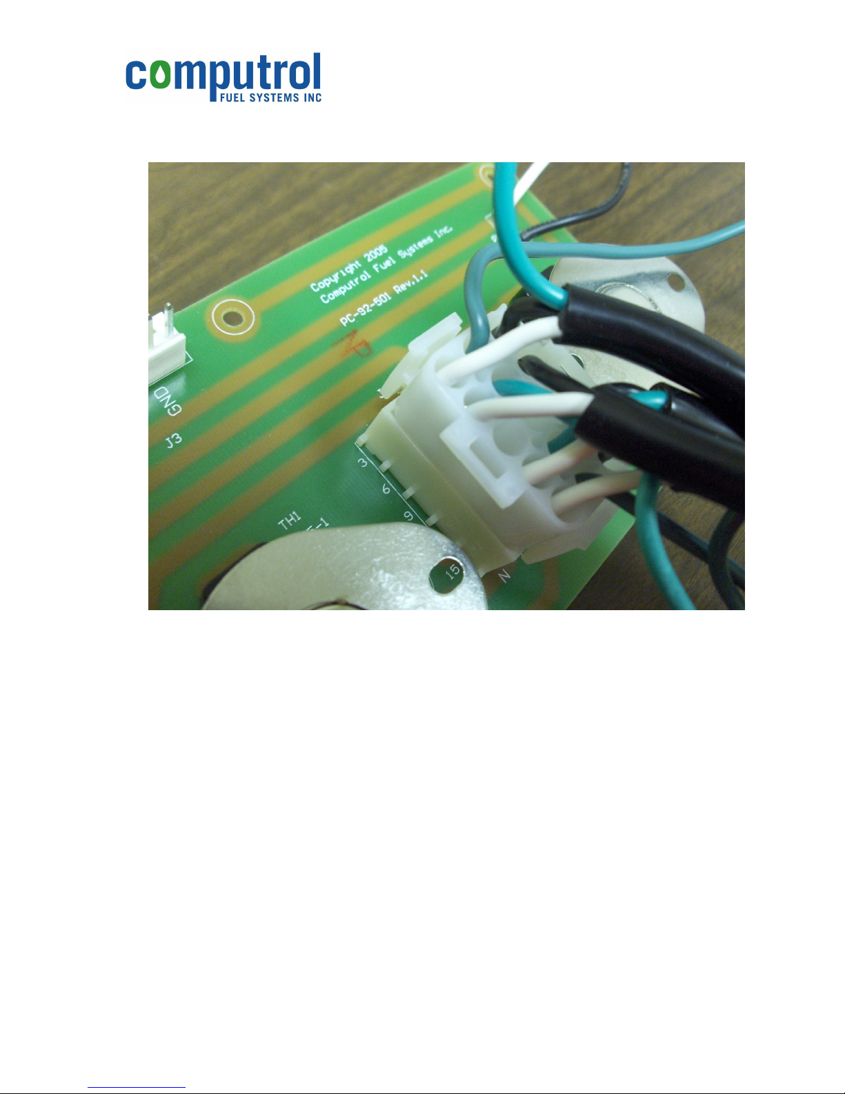
Figure 2 HEATER POWER CABLE (left) and C6000 POWER SUPPLY BOARD (right)
To connect the HEATER POWER CABLE:
a) Remove the 15-position connector: Depress the tabs on both ends, then
pull the connector off the POWER SUPPLY BOARD.
b) Insert the black (line) wire from the HEATER POWER CABLE into
position number four until it locks into place.
c) Insert the green (earth ground) wire from the HEATER POWER CABLE
into position number five until it locks into place.
d) Insert the white (neutral) wire from the HEATER POWER CABLE into
position number 6 until it locks into place.
Document PN 99-515
RP6000 Install-Op v1r2.doc
Page 2 of 13
Page 4
RP6000 Receipt Printer
Installation & Operation Manual
e) Re-insert the connector onto its header on the POWER SUPPLY
BOARD.
Figure 3 POWER SUPPLY BOARD wiring complete with HEATER POWER CABLE.
3. Remove the C6000 PCU POWER CABLE from the RECEPTACLE BOX and
plug it into a socket in the 3-OUTLET CORD (PN 78-001A).
4. Plug the “AC” POWER CORD from the Receipt Printer into a socket in the 3OUTLET CORD.
5. Plug the 3-OUTLET CORD into the RECEPTACLE BOX in the C6000 PCU.
6. Plug the SERIAL CABLE from the printer into the socket labeled J3 on the USER
INTERFACE (UI) board.
7. Ensure that all wiring is secure and neatly out of the way in the C6000 Enclosure.
Typically, there is room to tuck the 3-OUTLET CORD and associated wiring
along the left-hand side of the C6000 Power Supply.
Document PN 99-515
RP6000 Install-Op v1r2.doc
Page 3 of 13
Page 5
RP6000 Receipt Printer
Installation & Operation Manual
Setup
Profuel 2 Setup
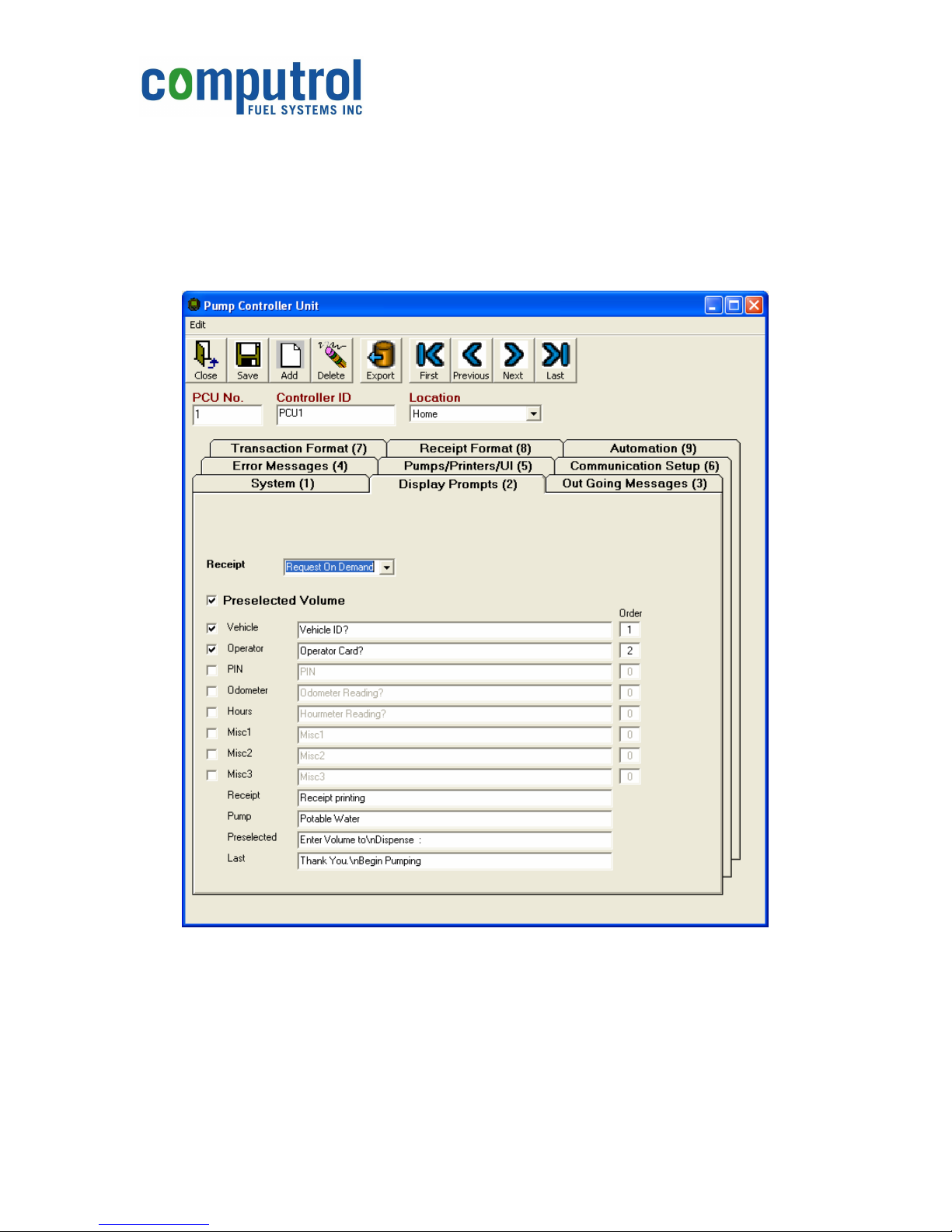
1. Start the Profuel 2 Fuel Management software, select the “PCUs” button, and
“Edit” the PCU to which the Receipt Printer is attached. The Pump Controller
Unit dialog box comes up:
Figure 4 Typical Pump Controller Unit dialog box
2. Click on the “Display Prompts (2)” tab as shown above, and change the drop-box
selection for “Receipt” to either “Yes” (always prints a receipt the next time the
operator cards in) or “Request On Demand” (the operator is prompted whether or
not to print a receipt the next time they card in).
3. Add or modify the display message for “Receipt”. This message will display
while the receipt is being printed, thereby notifying other users that the User
Document PN 99-515
RP6000 Install-Op v1r2.doc
Page 4 of 13
Page 6
RP6000 Receipt Printer
Installation & Operation Manual
Interface (UI) is busy and therefore the card reader/keypad cannot be used until
the receipt(s) are finished printing.
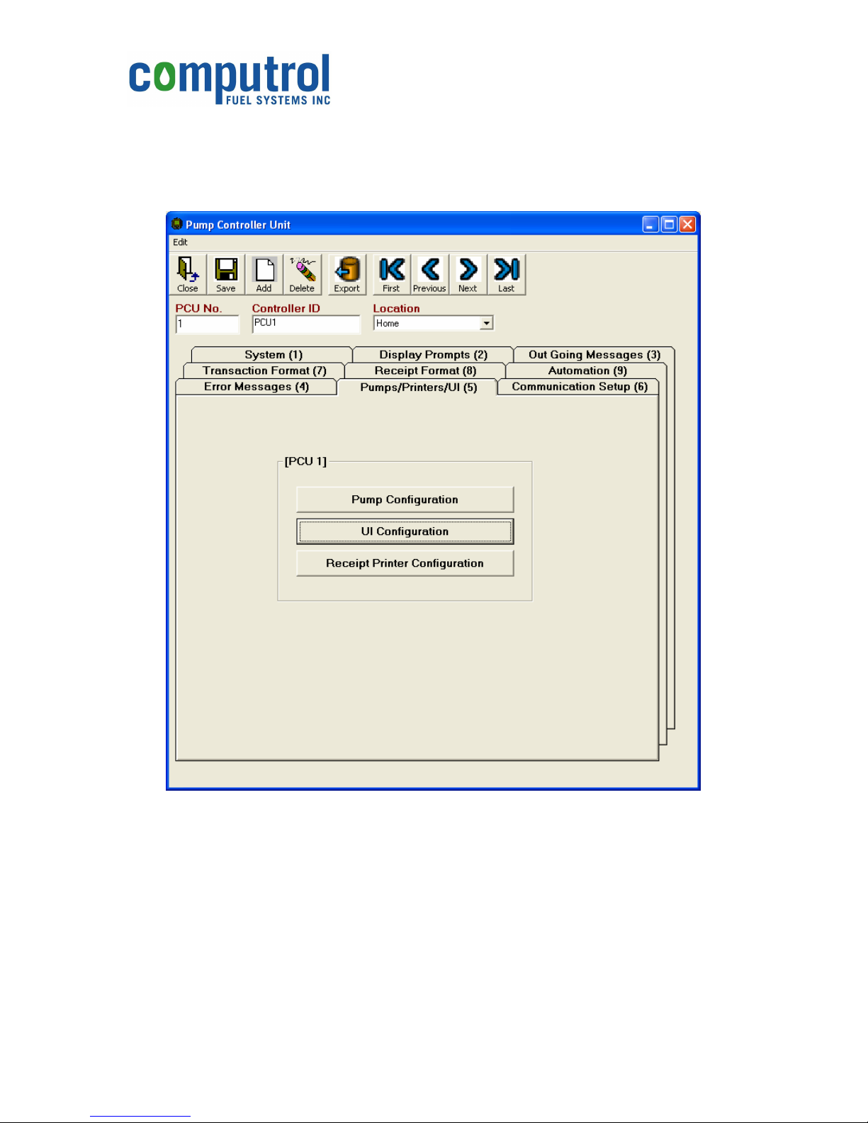
4. Click on the “Pumps/Printers/UI (5)” tab. Then click on the “UI Configuration”
button.
Figure 5 Click on "UI Configuration" button.
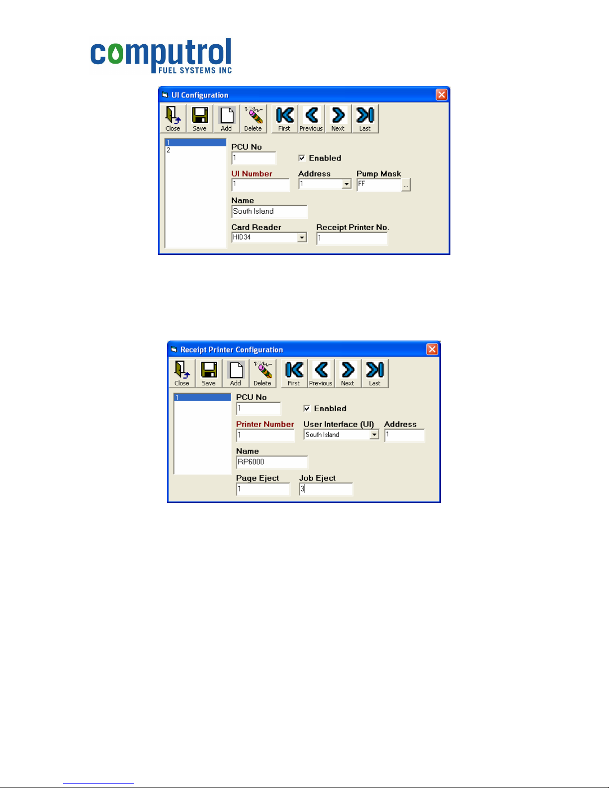
5. Click on the “Add” button and be sure to fill in the “Receipt Printer No.” box.
Document PN 99-515
RP6000 Install-Op v1r2.doc
Page 5 of 13
Page 7
RP6000 Receipt Printer
Installation & Operation Manual
Figure 6 UI Configuration dialog box.
6. Be sure to press the “Save” button, then “Close” the “UI Configuration Box”.
7. Back at the “Pumps/Printers/UI (5)” tab, click on the “Receipt Printer
Configuration” button.
Figure 7 Receipt Printer Configuration dialog box.
8. Click the “Add” button and fill in the appropriate info. A typical example is shown
above.
Be sure to click the “Enabled” checkbox so that as checkmark appears in it.
Use the dropbox to select the appropriate “User Interface (UI)”.
Be sure to put the correct “Address” in the appropriate box. Typically, this will be
address “1”, the same as the User Interface (UI) board.
Give the printer a “Name” to make it easier to recognize later on.
“Page Eject” should be filled in with an integer number representing the number of
blank lines to be inserted between receipts when printing multiple receipts at one
time.
Document PN 99-515
RP6000 Install-Op v1r2.doc
Page 6 of 13
Page 8
RP6000 Receipt Printer
Installation & Operation Manual
“Job Eject” should be filled in with an integer number representing the number of
blank lines to print at the end of a job before the paper cut.
9. Click on the “Save” button and then “Close” the “Receipt Printer Configuration”
box.
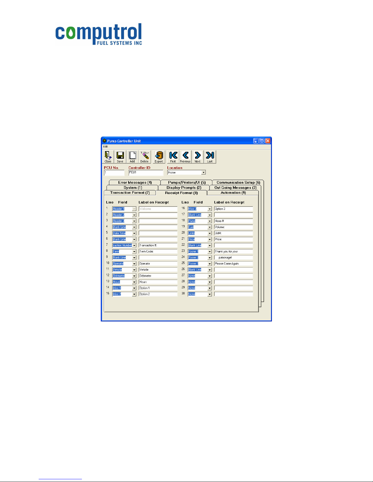
10. Click on the “Receipt Format (8)” tab. The information on this screen is used to
customize your receipts to include just the information you want to print.
For each line of the receipt, choose one of the fields available in the drop-boxes,
then customize the label for that field as you see fit. A typical example is shown
below:
Figure 8 Typical Receipt Format (8) dialog box.
11. Click on the “Save” button to save your configuration.
12. Click on the “Export” button to create a new “system.ini” file.
13. “Close” the “Pump Controller Unit” box.
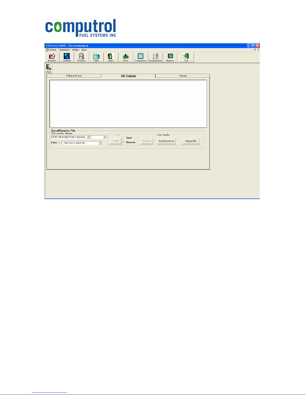
14. Click on the “Communications” box, then click on the “File Transfers” tab.
Document PN 99-515
RP6000 Install-Op v1r2.doc
Page 7 of 13
Page 9
RP6000 Receipt Printer
Installation & Operation Manual
Figure 9 Communications File Transfer dialog box.
15. Select the appropriate “PCU Location – Number” from the drop-down boxes.
16. Click on the Config System.ini” button to send the new configuration to the
C6000 Pump Control Unit.
17. Test the new receipt printer by running a test transaction.
Document PN 99-515
RP6000 Install-Op v1r2.doc
Page 8 of 13
Page 10
RP6000 Receipt Printer
Installation & Operation Manual
Servicing the Printer
Lock/Unlock
To open the Receipt Printer, it is necessary to unlock both of the key-locks on the front
door. The locks are unlocked by inserting the key and turning it 90° counter-clockwise.
To lock the Receipt Printer Again, push the Door in all the way. Press the door in firmly
to compress the gasket and then turn each key-lock 90° clockwise.
Paper Loading
Only thermal paper rolls with a maximum diameter of 120mm (4.7”), a width of 60mm
(2.36”), and a maximum paper thickness of 80m should be used with the RP6000
Receipt Printer. Using paper that does not meet these specifications may result in
paper jams and/or damage to the printer mechanism. Damage resulting from the
use of paper not meeting these specifications will not be covered under warranty.
1. Ensure that power is applied to the Receipt Printer.
2. Open the Receipt Printer and slide out the door and the PRINTER MECHANISM.
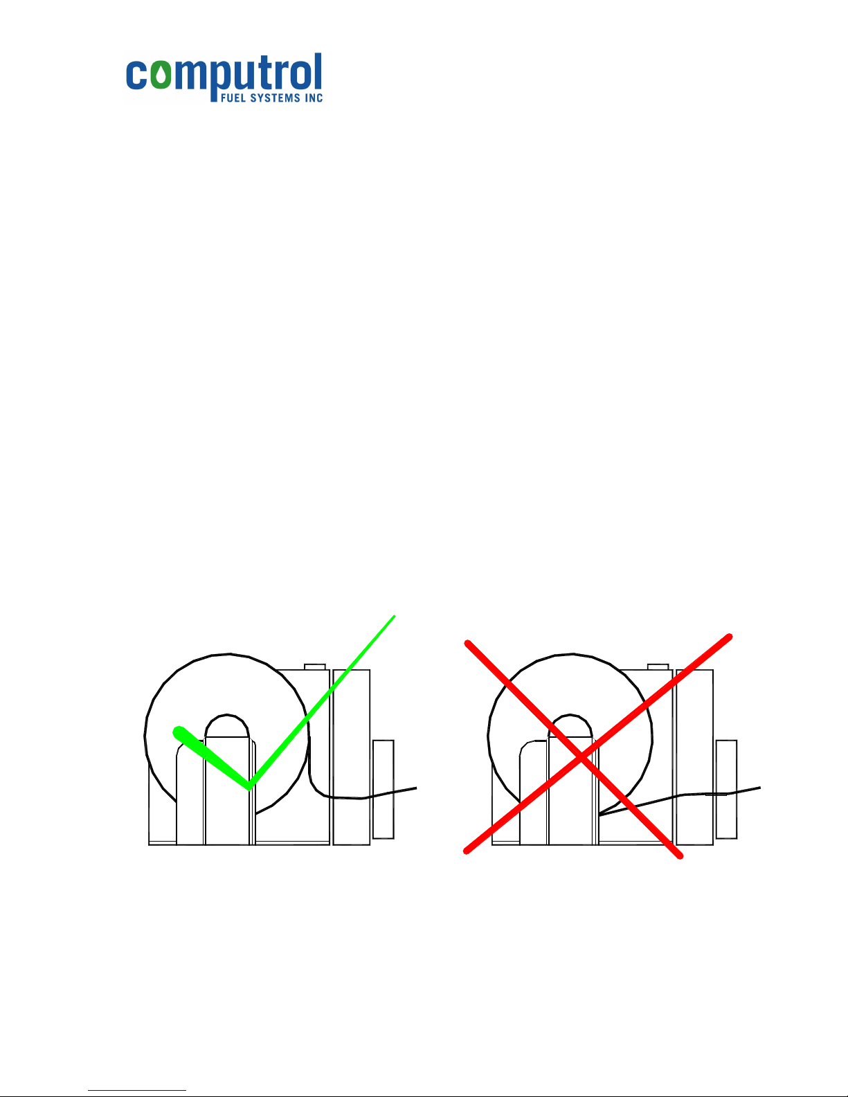
3. Obtain a fresh PAPER ROLL (PN 94-251). Orient the PAPER ROLL so that the
paper will feed from the top of the roll (see the diagram below), then insert the
loose end into the PAPER ENTRY SLOT. The printer will automatically feed the
paper through the mechanism when the paper is presented.
Figure 10 Correct and Incorrect Paper Loading
4. Pull back on the AXLE LEVER and seat the roll of paper into the right hand
PAPER AXLE. Release the AXLE LEVER, ensuring that the left-hand side of the
paper-roll seats properly on the left-hand PAPER AXLE.
Document PN 99-515
RP6000 Install-Op v1r2.doc
Page 9 of 13
Page 11

RP6000 Receipt Printer
Installation & Operation Manual
5. Press the PAPER FEED button on the top of the PRINTER MECHANISM to
advance approximately 20cm (8”) of paper through the PRINTER MECHANISM.
6. Push the PRINTER MECHANISM so that it slides back into the ENCLOSURE.
Feed the paper through the PAPER CHUTE opening at the rear of the DOOR
until it can be grasped out the front of the PAPER CHUTE. Then, tension the
paper with one hand while sliding the DOOR back into place.
7. Lock the DOOR before using the printer.
Paper Unloading
It can be desirable to replenish the paper roll before it runs completely out. To do so
follow the steps outlined below:
1. Cut the paper in the PAPER ENTRY SLOT from the remainder of the roll.
2. Use the PAPER FEED button on the top of the PRINTER MECHANISM to
advance the severed paper through the PRINTER MECHANISM and remove it
from the PAPER EXIT SLOT. Do not pull the paper through or try to pull it
backwards from the mechanism.
3. Remove the PAPER ROLL by pulling back on the AXLE LEVER and lifting it out.
4. Load a new PAPER ROLL as outlined above under “Paper Loading”.
Printing a Self-Test Ticket
A Self-Test Ticket can be printed to assist in determining the condition of your Receipt
Printer. To do this, remove power from the unit, unlock the DOOR and extend the
PRINTER MECHANISM out on its slide. Then press the PAPER FEED button and hold
it pressed while re-applying power to the unit. Once the printer goes through its
initialization, which takes a few seconds, it will begin printing a Self-Test Ticket. Once
printing begins, you may release the PAPER FEED button.
Document PN 99-515
RP6000 Install-Op v1r2.doc
Page 10 of 13
Page 12
RP6000 Receipt Printer
Installation & Operation Manual
Paper Cutter
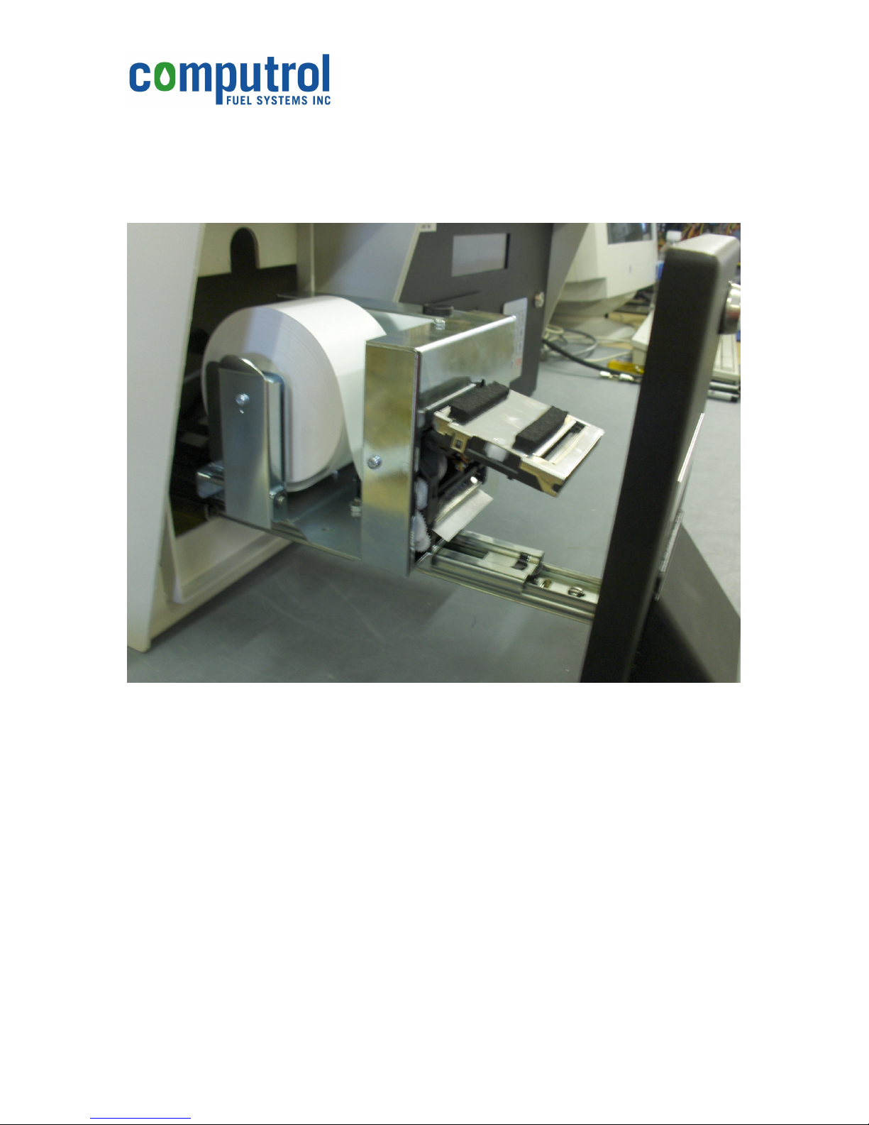
The PAPER CUTTER normally requires no maintenance, but may be swung open on its
hinges by gently prizing the bottom portion of the cutter out from the PRINTER
MECHANISM should a paper jam occur.
Figure 11 Paper Cutter shown in the open position.
It is not necessary to open the PAPER CUTTER for standard loading. Opening and then
closing the PAPER CUTTER without feeding the paper properly through the blades will
lead to a paper jam. In most cases it is better to remove all paper from the mechanism,
close the PAPER CUTTER, and then use the automatic loading feature of the printer
(see Paper Loading, above) to ensure correct paper feed.
Document PN 99-515
RP6000 Install-Op v1r2.doc
Page 11 of 13
Page 13
RP6000 Receipt Printer
Plug printer power supply in.
Installation & Operation Manual
Trouble-shooting
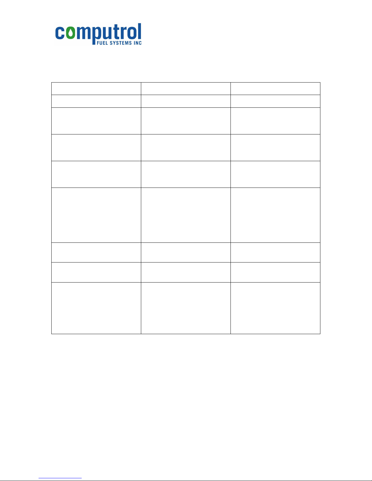
Refer to the following table for help in diagnosing problems with the printer.
Problem Possible Causes What To Do
Colored Stripe on the Paper Paper is low. Replace paper roll.
Receipt does not come out. Paper is jammed Inspect paper chute and
cutting knife; clear any
jammed paper.
Printer starts to print, but stops
while the receipt is being
printed
Receipt is not cut Paper is jammed. Inspect paper chute and
Print is light or spotty. Paper roll loaded incorrectly.
Vertical column of print is
missing.
One side of receipt is missing. This indicates a problem with
Printer does not function. Printer is not plugged in.
Paper is jammed. Inspect paper chute and
cutting knife; clear any
jammed paper.
cutting knife; clear any
jammed paper.
Ensure paper roll is loaded
Thermal print head is dirty.
Variations in paper.
This indicates a problem with
the printer electronics.
the printer electronics.
Printer is not connected to
PCU properly.
correctly.
Use recommended thermal
receipt paper.
Use recommended thermal
receipt paper.
Contact your authorized
service representative.
Contact your authorized
service representative.
Ensure power supply is
connected to rear of printer
mechanism.
Ensure correct serial data
connections to PCU.
Table 1 Trouble-shooting Guide
Document PN 99-515
RP6000 Install-Op v1r2.doc
Page 12 of 13
Page 14
RP6000 Receipt Printer
Installation & Operation Manual
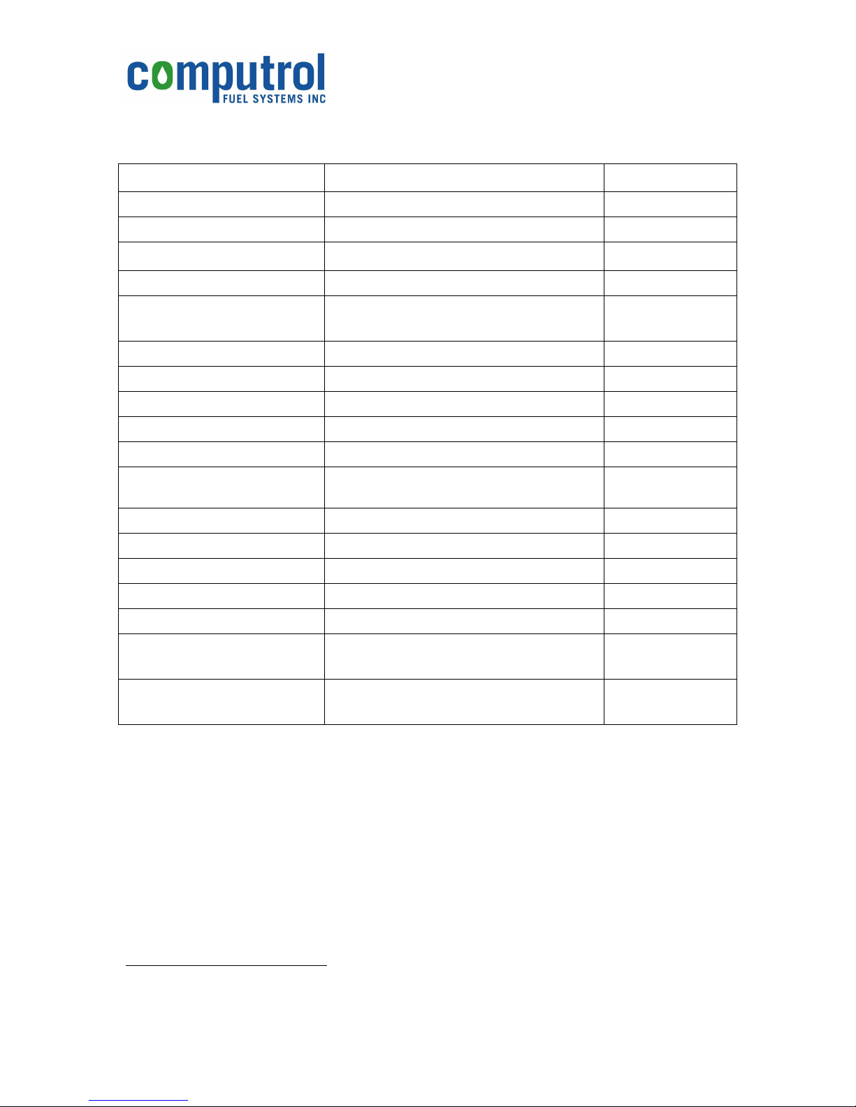
Specifications
Item Value Units
Printing Method Static thermal dot line printing n/a
Paper width 60 mm
Maximum paper thickness 80
Maximum paper roll diameter. 120 mm
Recommended paper. Computrol PN 94-250.
Computrol PN 94-251.
Characters per line 24
Printing speed 80 mm/sec
Printing width 48 mm
Resolution 8 dots/mm
Paper feed/dot line 0.125 mm
Paper loading. Lever and axle for roll, auto-load for paper
end
Paper empty detection By opto-sensor n/a
Storage temperature range -20 to +60 °C
Operating temperature range
Mechanical lifetime 50 km
Cutter lifetime 1,000,000 cuts n/a
Overall dimensions 267H x 191W x 395D
-20 to +50 non-condensing
10.5H x 7.5W x 15.6D
case of 12 rolls
m
single roll
n/a
°C
mm
inches
Weight 8.5
Table 2 RP6000 Specifications
Contact Computrol at:
***
Specifications subject to change without notification.
Document PN 99-515
RP6000 Install-Op v1r2.doc
19
***
Computrol Fuel Systems Inc.
107 – 1533 Broadway Street
Port Coquitlam, B.C.
Canada V3C 6P3
kg
lbs.
Page 13 of 13
 Loading...