

Page 1

Fireplace new platform product specification
The reproduction of this datasheet is NOT allowed without approval of Computime Limited. All information and data
contained in this datasheet are subject to change without notice. This publication supersedes and replaces all information
previously supplied. Computime has no responsibility to the consequence of using the information described in this
document.
Copyright © 2014 Computime Limited. All rights reserved. Rev. 1.2
Page 2
Fireplace new platform product specification
Scope: This document establishes the performance, design, test, and acceptance requirements for the
fireplace new platform controller.
Revision History
Rev.
Date
History / Change Prepared By
(DD-MM-YYYY)
0.1 20 February 2014 First draft WY Qu
0.2 09 April 2014 Second draft WY Qu
0.3 15 April 2014 Third draft
- Add more description on Backlight(3.1.16)
- Define model option(3.1.3)
- Clear low battery operation(3.1.11)
- Define Receiver operation (3.2.2)
- Modified pulse define(5.1.4)
- Define software flowchart
1.0 16 April 2014 Official Rev 1.0 release KL Tsang
1.1 20 June 2014 - At ‘Lo’ state, all keys can operate and send command
At ‘HI’ state, OFF key can operate only.(3.1.15)
- Add sensor error operation(3.1.17)
- Remain the status(OFF) from OFF to RS(3.2.2)
- Change Reset to power on(5.1.3)
- Update sensor error operation main loop of transmitter
- Add max temperature checking in flowchart
1.2 - Change Low battery detection operation(3.1.11)
- Resume the previous status from OFF to RS(3.2.2)
-
-
KLTsang
KLTsang
KLTsang
Copyright © 2014 Computime Limited. All rights reserved. Rev. 1.2
Page 3

Fireplace new platform product specification
Table of Contents
1 General Description .......................................................................................................................................... 1
2 System requirements...…………………………………………………………………………………………………2
3 Functional specifications................................................................................................................................... 3
4 RF Specifications .............................................................................................................................................. 8
5 RF protocol & commands………………………………………………………………………………………………8
6 Software specifications ................................................................................................................................... 10
7 Mechanical specifications ............................................................................................................................... 14
8 Regulatory specifications ................................................................................................................................ 14
9 Environmental specifications .......................................................................................................................... 14
10 Quality ........................................................................................................................................................... 14
11 Design test requirements .............................................................................................................................. 14
12 Warranty period ............................................................................................................................................ 14
13 Packaging ..................................................................................................................................................... 14
Copyright © 2014 Computime Limited. All rights reserved. Rev. 1.2
Page 4
Fireplace new platform product specification
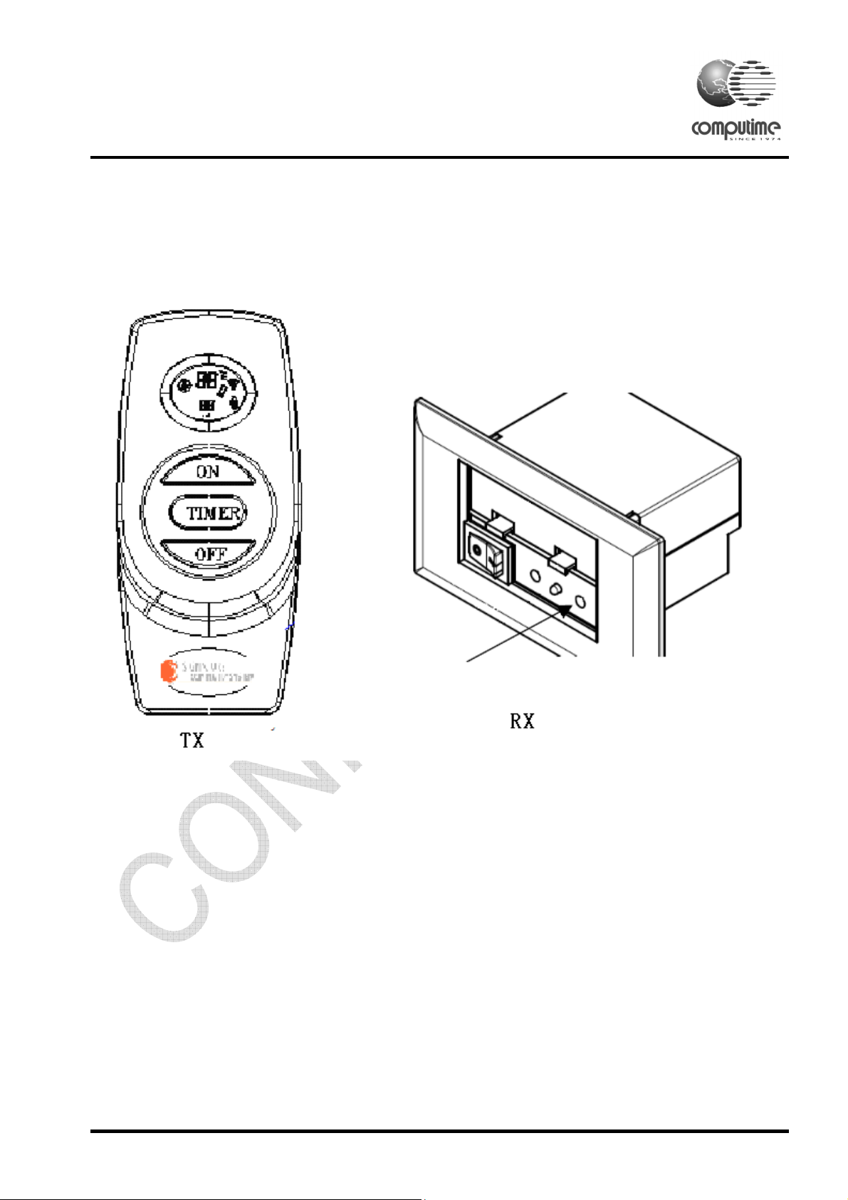
1 General Description
The fireplace controller is able to control the fireplace through the 350MHz wireless control,
including the temperature set function, detection and program control, and fan & ignition control
function. It includes the remote and receiver.
Copyright © 2014 Computime Limited. All rights reserved. Rev. 1.2
Page 1
Page 5
Fireplace new platform product specification
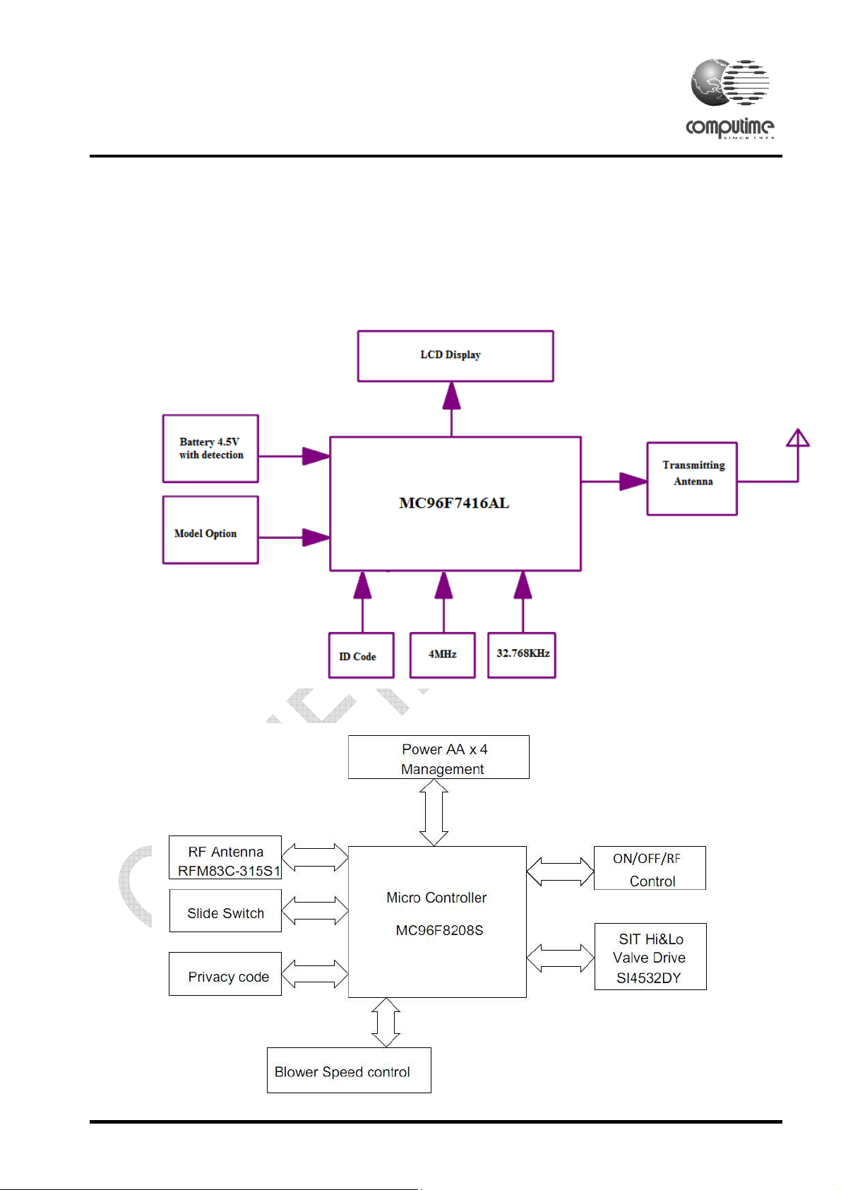
2 System requirements
To develop a RF remote and receiver control that will control the operation of a milli-volt gas
valve and Grand mate Stepper motor on the fireplace controller from a transmitter.
2.1. Remote system block diagram:
2.2. Receiver system block diagram:
Copyright © 2014 Computime Limited. All rights reserved. Rev. 1.2
Page 2
Page 6
Fireplace new platform product specification
3 Functional description
3.1 Transimitter functions:
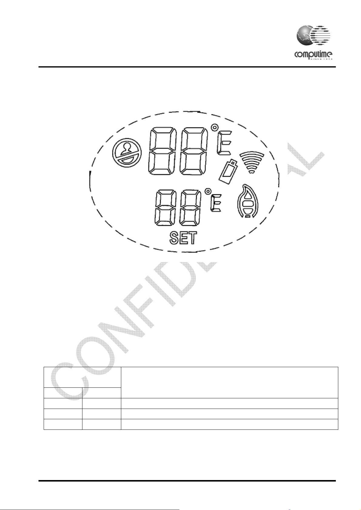
LCD display:
3.1.1 The Remote with LCD to show the temperature set, room teamperatre, flame height, RF icon,
low battery and child lock.
3.1.2 ℃ and ℉ degree selection: During system reset, all icons of the LCD display will be visible,
after one second, the LCD displays will be initialized and the backlight (R/G/B) will be on
simultaneously. The temperature scale is ℉ by default. Press ON button to select between ℃ and ℉.
If no key is pressed for 10 seconds, the remote will exit the setting mode automatically and enter the
main screen. The transmitter will send an OFF command after reset.
3.1.3 Model option: Select the models, which include ModelA_Tx1, ModelA_Tx2 and ModelB_Tx1.
Model Selection Pin
Model no
(Hardware defined)
Opt 1 Opt 2
1 1 ModelA_Tx1
1 0 ModelA_Tx2
0 1 ModelB_Tx2
3.1.4 RF Icon: When transmitter has commands being sent, the RF icon will be shown.
Copyright © 2014 Computime Limited. All rights reserved. Rev. 1.2
Page 3
Page 7

Fireplace new platform product specification
3.1.5 Manual Mode: Press the ON button once to turn on the fireplace with max flame height, and
then press the OFF button to decrease flame height, the first two pressing with decrease flame height
to lower level. The third pressing will be turn fireplace off. (Flame height adjustment only for
ModelA_Tx1)
ModelA_Tx2 and ModelB_Tx1 only Flame ON and Flame OFF, not flame height adjustment. Flame
icon only showed max flame height and Off.
.
3.1.6. Ruber key button and buttons function:
Copyright © 2014 Computime Limited. All rights reserved. Rev. 1.2
Page 4
Page 8

Fireplace new platform product specification
3.1.7 Auto mode: Press the AUTO button to enter the thermostatic mode. SET icon will be
appeared on the lower LCD screen. In thermostatic mode, press ON button or OFF button to set the
desired set temperature. Once the setting is completed, the transmitter will be automatically turned
on the fireplace when the room temperature is below the set temperature. The transmitter will be
turned off when above the set temperature. The temperature range is within 1 degree. There will be
a slight delay in the response of the unit (on/off) to a temperature. Room temperature is monitored
every 3 minutes. Press the AUTO button to exit the thermostatic mode. The SET icon will be
disappeared on the LCD display. The transmitter will be in the manual on/off mode. The AUTO
mode only for ModelB_Tx1.
3.1.8 Timer mode: Press the Timer button to start the timer, 90 min as shown in LCD and SET icon
below 90 in LCD. 2ND press the Timer button, the timer will be set to 60 min, 3
rd
press the timer
button the timer will be set to 30 min. Three seconds later, the tranmsitter will be turn on the
fireplace.
Once the timer is 0 min, the transmitter will be send off signal and turn off the fireplace.
Press the OFF button to exit the timer mode and the transmitter will be shut off the fireplace.
3.1.9 Room temperature: Show the current room temperature, display temperature range: 40℉-99℉
(5-37℃), accuracy is +/-1℃. every 3 minute to check the room temperature.
3.1.10 The temperature setting range are 45℉-90℉(7-32℃).
3.1.11 Low battery: When the battery voltage of remote is less than 3.4V, the low battery icon will
be shown. The battery will be checked every minute. If the battery voltage of remote is less than
3.2V, the remote will send the flame OFF command to the receiver and turn off the flame.
3.1.12 Child lock - When press and hold the ON and OFF buttons for 3 seconds, the
remote will be locked, the LCD will show the child lock icon and current status, and user cannot
change any setting when pressing the buttons. It will be unlocked when press and hold the ON and
OFF buttons again for 3 seconds.
Copyright © 2014 Computime Limited. All rights reserved. Rev. 1.2
Page 5
Page 9

Fireplace new platform product specification
3.1.13 ID code.
There are 4 bit Dip switch for remote and receiver, the remote ID set must match receiver, If not, the
remote will be can’t control the receiver.
3.1.14 Reset button: The Reset button in left of ID DIP switch, press the Reset button to reset the
remote and initialization, re-select the ℉ or ℃ again.
3.1.15 High temperature shut down: if the transmitter measures a room temperature exceeding 99 ℉
or 37℃, the LCD will display “HI” and the transmitter will turn off the fireplace. The transmitter
will function on OFF key only until the room temperature has droped below 99 ℉ or 37℃. (for
safety issue)
If the transmitter measures a room temperature less than 40℉ or 4℃, the LCD will display “Lo” .
The all keys can operate and can be sent the commands to operate the fireplace.
3.1.16 Backlight: The backlight colour will change according to the current temperature range. If the
room temperature over the 26℃(78℉), then the backlight will be Red. If room temperature less than
16℃(61℉), the backlight will be Green. Backlight will be Blue if the room temperature is between
16-26℃. When any key is pressed the backlight will turn on for 8 seconds and then turn off.
3.1.17 Sensor Error: If the temperature sensor circuit is opened, display “E0”. If the temperature
sensor circuit is shorted, display “E1”. Both cases would lock up all keys and shut down all
operating processes until reset its power again. Whenever a sensor error is detected, transmitter must
turn off the flame. (for safety issue)
Copyright © 2014 Computime Limited. All rights reserved. Rev. 1.2
Page 6
Page 10

Fireplace new platform product specification
3.2. Receiver functional specification:
3.2.1. ID setting: The receiver ID must match with transmitter ID. The 4 position DIP switch will
applied for receiver board.
3.2.2 Slide Switch: The slide switch should be used to perform the manual control or specific
functions as defined for each individual receiver.
The fireplace operation should start at remote position. When slide switch starts from ON or OFF
position after new battery installed or reset, no operation should perform and system should be in
shutdown states. When fireplace starts at remote position, the fireplace will be in flame off state.
The fireplace starts the fire control if it receives the flame on command from transmitter.
When slide switch moves from RS to ON position, the fireplace should be turned on at its highest
flame height. Six hour shutdown operation should not be performed.
When slide switch moves from ON to RS position, the fireplace should resume the previous state
operated at RS position.
When slide switch moves from RS to OFF position, the fireplace should be shut off. Six hour
shutdown operation should not be performed.
When slide switch moves from OFF to RS position, the fireplace should resume the previous state
operated at RS position.
3.2.3 During power up the receiver, the LED will flash 3 times, and the duration is 500ms on every
flash. Then, LED will turn on 5 seconds. After that, LED will turn off.
3.2.4 Connector: A 2pins connectors should be used to provide all external connection for ON/OFF
control.
3.2.5 RF module and Antenna: A 350MHz RF module is used for communication with Remote. It
must meet the range of more than 30 feet when the receiver assembly on fireplace.
Copyright © 2014 Computime Limited. All rights reserved. Rev. 1.2
Page 7
Page 11

Fireplace new platform product specification
3.2.6 Battery: AA * 4 Alkaline battery for receiver power supply. The four AA battery lifetime
should be enough to perform at least four operations ON and OFF in a day for minimum 240 days.
The low battery monitoring circuit should indicate the low battery condition at 3.9V. The fireplace
should shut down completely and receiver should not accept any command form transmitter once
battery drops below 3.9V for four AA batteries, LED will flash every 60 second until battery totally
drains out.
3.2.7 LED indication: The receiver should provide the indication when it receives and decodes the
commands from transmitter correctly. The on-board LED should be implemented to perform this
function.
3.2.8 Six Hour Shutdown: The receiver should be shut down completely six hours later if it does
not receive valid command from transmitter. No shutdown is required when slide switch is at ON or
OFF position.
3.2.9 A 5Pin programmer port should be used for online programming.
4 RF Specifications
350MHz RF frequency
More than 30 feet RF Range
5 RF protocol & commands
The following protocol defines the wireless control commands for the fireplace. All commands must
follow the protocols.
5.1 Code description
5.1.1 Each command consists of 4 start bits, 4 address bits and 8 data bits
5.1.2 The transmitted sequence is as follows:
S0 S1 S2 S3 A3 A2 A1 A0 D7 D6 D5 D4 D3 D2 D1 D0
S0 - S3 start bits.
A0 - A3 specified by on-board dip switch. A3: MSB, A0: LSB
D0 - D7 command bits are defined by the following tables:
5.1.3. Commands:
Items
1010xxxx00000000 Ax00 Off
1010xxxx00000001 Ax01 On
1010xxxx01010000 Ax50 After reset
Command
Command, Hex
Function
Copyright © 2014 Computime Limited. All rights reserved. Rev. 1.2
Page 8
Page 12

Fireplace new platform product specification
5.1.4 Pulses define:
5.1.4.1 Wide pulse is defined as bit ‘0’ and narrow pulse as bit ‘1’.
5.1.4.2 Wide pulse width is 640us and narrow width as 320us, +/-10%.
5.1.4.3 Duration between two pulses ( pulse rising edge to previous falling edge): for next wide
pulse: 640us and for next narrow pulse: 320us.
5.1.4.4 Duration between each16 bit command: 12ms +/-10%
5.1.4.5 Total Number of Command: 2.6s, +/-10%
5.1.4.6 The start bits for each 16 bit command are defined as ‘1010’.
Copyright © 2014 Computime Limited. All rights reserved. Rev. 1.2
Page 9
Page 13
No
No
Toggle Display
and
Display all icons
1
Initial 10sec timer
Fireplace new platform product specification
6 Software specification
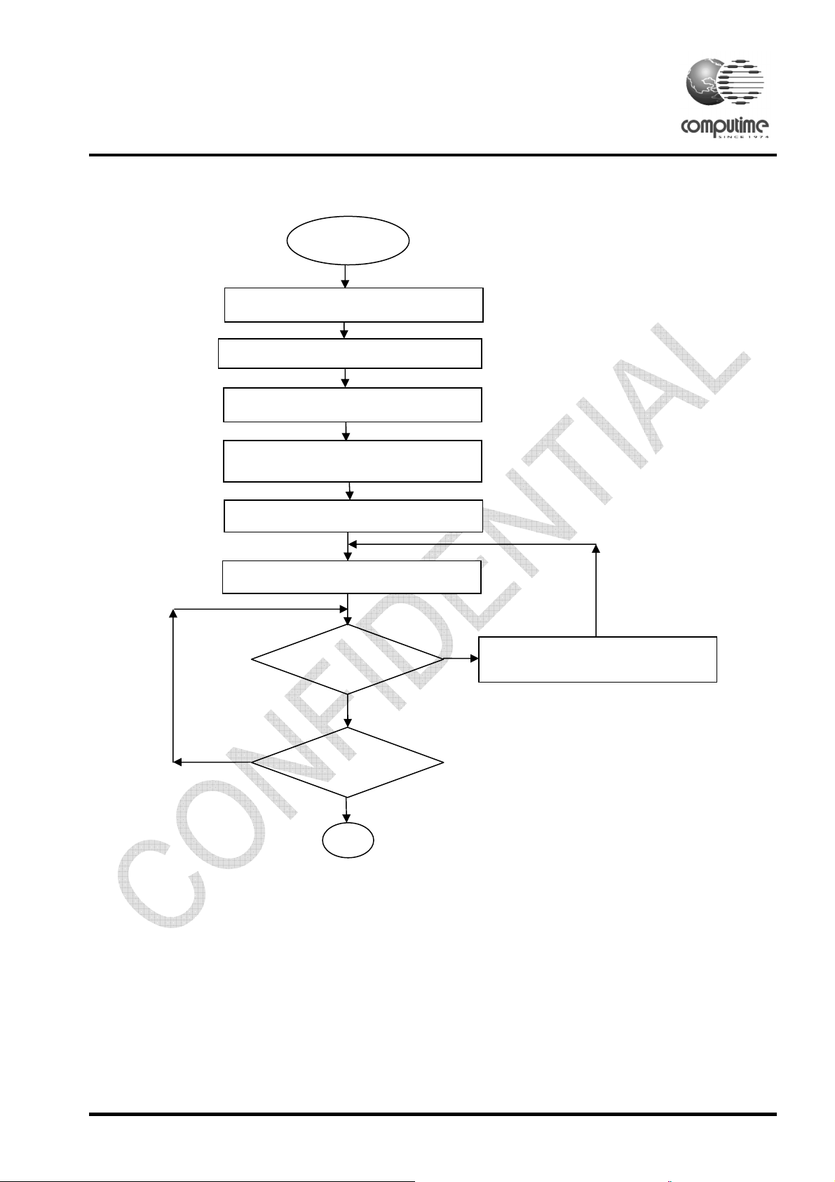
6.1 Program flowchart of Start(Reset/power up)
Start
Initial Hardware port
Read the DIP switch(pairing code)
Read Option to set model
Set backlight On
(R->B->G)
Check “ON” key
press?
Wait 10sec
timeout?
Yes
Yes
℉
℃
Copyright © 2014 Computime Limited. All rights reserved. Rev. 1.2
Page 10
Page 14

No
No
Yes
No
Set Child lock
No
No
No
Yes
No
Fireplace new platform product specification
6.2 Main Loop of transmitter
Check sensor and temp. conversion
Open circuit
Check sensor
Short circuit
valid?
Display “E0”
Sensor OK
Check Temp.
Greater than 99℉
Display “E1”
range?
between 40 and 99℉
Display “Lo” display Room Temp Display “Hi”
Yes
Low Battery icon
First
time?
Yes
Send Off
command
Send Off command
Low battery
<3.4V?
Low battery
<3.2V or Hi
temp?
First Time
send Off?
Exit Child
lock
Yes
Hold ON/OFF
in 3s ?
Yes
Child lock ?
Hold ON/OFF
in 3s ?
Yes
Copyright © 2014 Computime Limited. All rights reserved. Rev. 1.2
Page 11
Page 15

No
No
?
turn off flame
No
No
No
No
Increment Temp. value
No
Decrement Temp. value
No
No
No
Send Off command
No
No
4
No
Send On command
No
ModelA_Tx2
only
Fireplace new platform product specification
Display High Flame,
send On command
AutoFlag
=1 ?
Yes
Model: ModelA_Tx1,
Display Timer loop
from 90 to 0
Timer
=0?
Yes
Clear Flame icon,
Send Off command
Yes
Yes
ON
Key ?
OFF Key?
Timer
Key ?
Yes
AutoFlag
=1 ?
Flame
Adj?
Send Off command
Yes
Yes
Model: ModelB_Tx1 only
Decrement
Flame icon
Flame
icon=0
Yes
Clear Timer icon,
turn off flame
Auto
Key ?
3min
timeout?
Copyright © 2014 Computime Limited. All rights reserved. Rev. 1.2
Yes
Yes
AutoFlag
AutoFlag=0,
Clear set Temp.
AutoMode
=1?
Yes
=0?
Yes
AutoFlag=1,
Display set Temp.
Compare
temp >1?
Yes
Compare
temp <1?
Yes
Page 12
Page 16

No
No
Fireplace new platform product specification
Model: MHNMSC1,
MHNCMT1 only
Timer
Set?
Flame
on?
Yes
Timer =
TimeVal?
Yes
Clear Flame icon,
turn off flame,
clear Timer flag
Send Off command
Yes
Temp>
max?
Update display
Yes
Clear Flame icon
Send Off command
Sleep
6.3 Timer interrupt
Read temp.
Wake up
timeout
Timer
timeout(1 min)
TimerVal
=TimerVal+1
Wake up
Copyright © 2014 Computime Limited. All rights reserved. Rev. 1.2
Page 13
Page 17

Fireplace new platform product specification
6.4 Key(I/O) interrupt
Key interrupt
Wake up
7 Mechanical specification
8 Regulatory specifications
FCC Comply.
9 Environmental specifications
Operating temperature: 0-50℃.
Storage temperature: -10-60℃.
5-90% Humidity
10 Quality
Quality parameters: all products must be fir for function. Any deviations from the product Specification
will be considered a defect and will cause rejection of the product.
Product life expectancy is 5 years, based on 5000 hours usage per year.
Workmanship: All parts shall meet the IPC-A-610D.
11 Design test requirements
a). Life Testing
Sample size of 10 units must survive ALT equivalent to 15000 hours.
d). ESD 8KV Class B.
12 Warranty period
One Year
13 Packaging
TBA
Copyright © 2014 Computime Limited. All rights reserved. Rev. 1.2
Page 14
Page 18

FCC Statement
This device complies with part 15 of the FCC Rules. Operation is subject to the
following two conditions: (1) this device may not cause harmful interference, and (2)
this device must accept any interference received, including interference that may
cause undesired operation.
This equipment has been tested and found to comply with the limits for a Class B
digital device, pursuant to Part 15 of the FCC Rules. These limits are designed to
provide reasonable protection against harmful interference in a residential installation.
This equipment generates, uses and can radiate radio frequency energy and, if not
installed and used in accordance with the instructions, may cause harmful
interference to radio communications. However, there is no guarantee that
interference will not occur in a particular installation.
If this equipment does cause harmful interference to radio or television reception,
which can be determined by turning the equipment off and on, the user is encouraged
to try to correct the interference by one or more of the following measures:
-- Reorient or relocate the receiving antenna.
-- Increase the separation between the equipment and receiver.
-- Connect the equipment into an outlet on a circuit different from that to which the
receiver is connected.
-- Consult the dealer or an experienced radio/TV technician for help.
Changes or modifications not expressly approved by the party responsible for
compliance could void your authority to operate the equipment.
Canada – Industry Canada (IC)
This device complies with Industry Canada license-exempt RSS
Standard(s). Operation is subject to the following two
conditions:
1. (1) this device may not cause interference, and (2) this device
must accept any interference, including interference that may
cause undesired operation of the device.
Cet appareil est conforme avec Industrie Canada exempts de
licence standard RSS (s). Son fonctionnement est soumis aux
deux conditions suivantes:
(1) cet appareil ne doit pas provoquer d’interfé
cet appareil doit accepter toute interference, y compris celles
pouvant causer un mauvais fonctionnement de l’appereil
rences et (2)
 Loading...