

Page 1
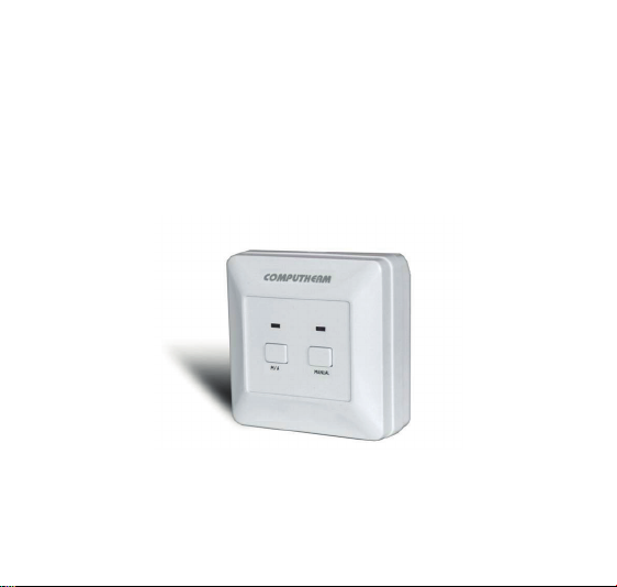
COMPUTHERM
Wireless receiver unit
(radio-frequency) for
room thermostats
Operating Instructions
Q7RF (RX)
COMPUTHERM
Page 2

A GENER AL DESCRIPTION OF THE
RECEIVING UNIT
Room thermostat receiver
is suitable to operate together with wireless room
thermostats
Q5RF,
The
COMPUTHERM
room thermostat receiver controlled by a wireless
COMPUTHERM
overwhelming majority of boilers and air conditioners.
It can easily be connected to any gas boiler or air
conditioning device that has a double wire connector
for a room thermostat, regardless of whether it has a
24 V or 230 V control circuit. The receiving unit controls
the connected gas boiler or another electric device
according to signals coming from the room thermostat
switch.
If you want to make your gas convector controllable
with a room thermostat using
COMPUTHERM
COMPUTHERM
Q7RF (RX) type switched-mode
room thermostat is suitable to regulate the
COMPUTHERM
Q3RF,
Q7RF and
COMPUTHERM
- 2 -
Q7RF (RX )
COMPUTHERM
COMPUTHERM
KonvekPRO
Q8RF.
Page 3

and a
you wish to control several gas heaters with a single
room thermostat, you can accomplish this task by
means of a
A single
be synchronized with several
(RX) receiver units at the same time, and this make
simultaneous control of several gas convectors feasible
(for more details please refer to Chapter 1).
COMPUTHERM
COMPUTHERM
COMPUTHERM
wireless room thermostat and
Q7RF (RX) receiver unit.
wireless room thermostat can
COMPUTHERM
Q7RF
1. INSTALLATION AND CONNECTION
OF THE RECEIVER UNIT
The
COMPUTHERM
mounted on the wall in a place protected against moisture and heat, in the vicinity of the boiler. When choosing
the location of the receiving unit you should remember
that bulky metal objects (e.g. a boiler, buer tank, etc.)
and metal building structures may have an adverse effect on propagation of radio waves. If it is possible, in
order to ensure trouble-free RF connection, we recom-
Q7RF (TX) receiver unit should be
- 3 -
Page 4

mend that you install the receiving unit at a height of 1.5
to 2 m and at a distance of 1 to 2 m from the boiler or other bulky metal constructions. We recommend that you
check reliability of RF connection at the place selected
before installing the receiving unit.
ATTENTION! Do not install the receiver unit under
the housing of the boiler or near hot pipes because it
may damage the parts of the device or compromise
wireless (radio-frequency) connection. To avoid
electric shock, entrust a specialist with connecting
the receiver unit to the boiler!
The device must be installed and connected by a
qualied professional.
WARNING! Modifying the thermostat can cause
electric shock or product failure.
Unscrew the two screws at the bottom of the receiver
unit without removing them. Following this, remove the
front panel of the receiver unit then x the back panel to
the wall in the vicinity of the boiler with the screws pro-
- 4 -
Page 5

vided. Remove the protective carton from the contacts to
ensure perfect contact.
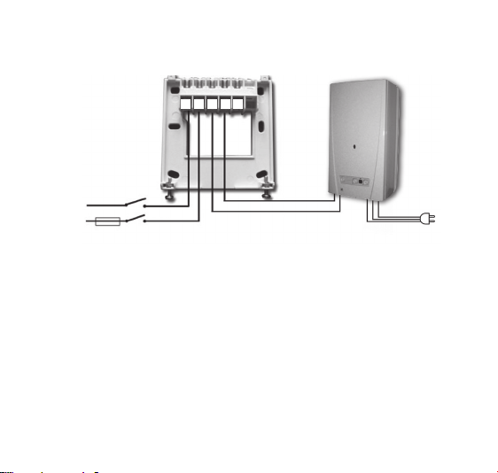
The marks of the connections are pressed into the plastic above the connection points: N, L, 1, 2 and 3.
230 V mains voltage should be supplied to the receiver
unit. This provides the power supply for the device, but
this voltage does not appear on the terminals 1 and 2.
We propose to connect the neutral wire of the network to
point N, while the phase conductor to point L. We recommend using a fork type connection including a switch for
mains connection. Please de-energize the device when
heating is continuously not needed (e.g. summer).
The receiver unit controls the boiler or air conditioner
through a potential-free alternating relay whose connection points are: 1 (NO), 2 (COM) and 3 (NC). Connect the two connection points of the heating or cooling
equipment to be controlled to terminals No. 1 (NO) and
No. 2 (COM), i.e. to the normally open terminals of the
relay as shown in the gure.
- 5 -
Page 6
Rear panel of the
receiver unit
230 V AC
50-60 Hz
N
COM
NO NC
LN 1 2 3
Heating unit (boiler)
L (phase)
230 V AC, 50-60 Hz
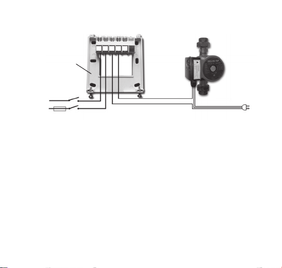
If you would like to operate an old boiler or any other device that has no connection points for thermostats, then
the No. 1 (NO) and No. 2 (COM) connection points of
the thermostat should be connected to the mains cable
of the device, similarly as a switch would be connected.
- 6 -
Page 7
Rear panel of
the receiver
unit
230 V AC
50-60 Hz
N
L
(phase)
COM
NO NC
LN 1 2 3
Pump (heater / infrapanel etc.)
230 V AC, 50-60 Hz
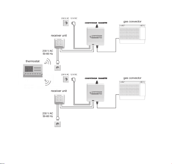
If you want to control several gas convectors by using a
single room thermostat then you need a
COMPUTHERM
wireless room thermostat (it already comprises a receiving
unit), and as many
COMPUTHERM
KonvekPRO gas convector
controllers as the number of gas convectors to be controlled
and one less
COMPUTHERM
Q7RF (RX) supplementary
receiving units. The gure below shows control of two gas
convectors with a single wireless room thermostat. In case
of more than two gas convectors a similar arrangement
can be implemented by additional receiving units and
COMPUTHERM
KonvekPRO gas convector controllers.
- 7 -
Page 8
- 8 -
Page 9
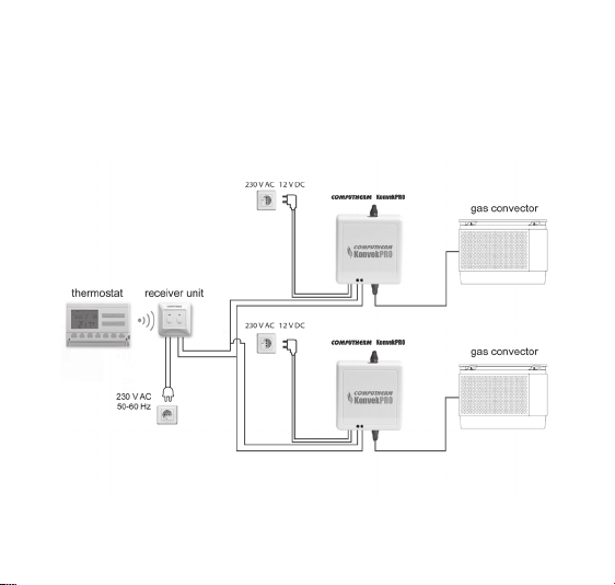
When you are able to establish wired connection between
the gas convectors, you can also set up the system by
using fewer
shown in the gure below.
COMPUTHERM
Q7RF (RX) receiving units as
- 9 -
Page 10

ATTENTION! Always consider the loadability of the receiver unit and follow the manufacturer’s instructions
of the heating or cooling equipment. The device must
be installed and connected by a qualied professional!
The voltage appearing at terminals No. 1 (NO) and No.
2 (COM) depends only on the system being controlled,
therefore the dimensions of the wire are determined by
the type of the device to be controlled.
The length of the wire is of no signicance, the receiver
unit may be installed either near the boiler or far away
from it, but do not install it under the housing of the
boiler.
If the distance between the transmitter and receiver units
is too large due to local circumstances and it makes the
wireless (radio-frequency) connection unreliable, install
the receiver unit nearer to the place of thermostat or use
a
COMPUTHERM
communication distance.
Q2RF signal repeater to increase the
- 10 -
Page 11

2. PUTTING THE RECEIVER UNIT
INTO OPERATION
Turn on the power supply to the receiver unit. Press the
“M/A” button of the receiver unit and keep it depressed
(for approximately 10 seconds) until the green LED
starts ashing. Following this, synchronize the thermo-
stat with the receiver unit(s) according to the instructions for use of your room thermostat. The synchroniza-
tion was successful if the green LED stops ashing and
goes out, so that the receiver unit “learns” the safety
code of the transmitter (thermostat). The safety code
will not be lost even during a power outage, the device
memorizes it automatically.
3. TRANSMISSION DISTANCE INSPECTION
You can check proper functioning of wireless (RF) connection between the wireless (RF) thermostat and the
receiver units by following instructions for use provided
for the thermostat being used.
- 11 -
Page 12

4. MANUAL CONTROL OF THE RECEIVER UNIT
Pressing the “MANUAL” button separates the thermostat
from the receiver unit. In this case, the boiler or air conditioner connected to the receiver unit can only be turned on
and o manually, without any temperature inspection. The
continuously illuminated green LED indicates “MANUAL”
mode. Pressing the “M/A” button turns on or o the boiler.
(The red LED is illuminated when the boiler is turned on).
By pressing the “MANUAL” button again, the device quits
manual control and resumes automatic (thermostat-con-
trolled) operation (the green LED goes out).
- 12 -
Page 13
FREQUENTLY ASKED QUESTIONS
When you think that your appliance is operating incorrectly or encounter any problem while the appliance is being
used then we recommend that you read Frequently Asked
Questions (FAQ) available on our website, where we collected the problems and questions that most frequently
occur while our appliances are being used, along with the
solutions thereto:
http://www.quantrax.hu/gyik/
The vast majority of the problems encountered can be
solved easily by using the hints available on our website,
without seeking professional help. If you have not found a
solution to you problem, please pay a visit to our qualied
service.
- 13 -
Page 14

Warning! The manufacturer does not assume responsibility for any direct or indirect damages and loss of
income occurring while the appliance is being used.
- 14 -
Page 15

PRODUCT INFORMATION DATA SHEET:
• Trademark:
• Model identier: Q7RF (RX)
TECHNICAL DATA
‒ power supply voltage: 230 V AC, 50 Hz
‒ power consumption: 0,01 W
‒ switchable voltage: 24 V AC/DC to 250 V AC, 50 Hz
‒ switchable current: 6 A (2 A inductive load)
‒ transmission distance: approx. 50 m in open terrain
‒ protection against
environmental impacts: IP30
‒ weight: 150 g
- 15 -
Page 16
The
COMPUTHERM
Q7RF (RX) type thermostat
complies with the requirements of standards
RED 2014/53/EU and RoHS 2011/65/EU.
Manufacturer: QUANTRAX Kft.
Fülemüle u. 34., Szeged, H-6726, Hungary
Phone: +36 62 424 133 • Fax: +36 62 424 672
E-mail: [email protected]
Web: www.quantrax.hu • www.computherm-hungary.hu
Origin: designed in the EU, made in China
Copyright © 2018 Quantrax Ltd. All rights reserved.
 Loading...