

Page 1
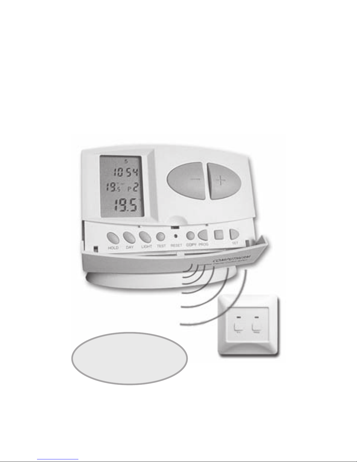
COMPUTHERM
Q7RF
Programmable wireless (radio-frequency)
digital room thermostat
Operating Instructions
NEW
software!
For Evaluation Only.
Copyright (c) by Foxit Software Company, 2004
Edited by Foxit PDF Editor
Page 2
GENERAL DESCRIPTION OF THE THERMOSTAT
The
COMPUTHERM
Q7RF type switched-mode room thermostat is suitable
to regulate the overwhelming majority of boilers and air conditioners available
in Hungary. It can easily be connected to any gas boiler or air conditioning
device that has a double wire connector for a room thermostat, regardless of
whether it has a 24V or 230V control circuit.
The device can be programmed according to customer-specic requirements
so that the heating/cooling system heats/cools your residence or ofce to
the required temperature at the dates and times specied by you, to reduce
energy costs while maintaining comfort. Separate temperature programs can
be prepared for each day of the week. For each day, beside 1 xed switching
time, 6 adjustable switching times can be set and a different temperature can
be assigned to all 7 switching times.
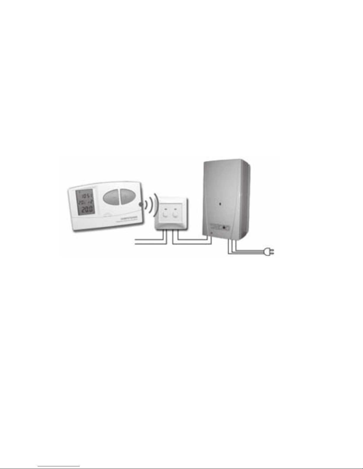
The device consists of two units. One of them is the portable control unit
(thermostat), while the other unit is the receiver that controls the boiler. Because
there is a wireless (radio-frequency) connection between the two units, no
cable is required between the thermostat and the boiler. The two units have
been tuned in the factory so that they operate at the same frequency. The
trouble-free operation is ensured by its own security code. The installation
and connection of the receiver unit is described in Section 9.
To increase the lifetime of the batteries, the thermostat will not transmit signals
continuously. Instead it will repeatedly transmit the actual signal every 8
minutes. Therefore, the regulation of the heating or cooling will continue even
after a blackout.
The portability of the thermostat offers the following advantages:
no need to lay a cable, which is especially advantageous when old
•
buildings are being modernized,
the optimal location of the device can be selected during operation,•
it is also advantageous when you intend to locate the thermostat in different •
rooms in the course of the day (e.g. in the living room during the day but
in the bedroom at night).
- 2 -
Boiler
Reciever
230V AC
50-60 Hz
Thermostat
230V AC
50-60 Hz
Page 3
The effective range of the transmitter incorporated in the thermostat is
approximately 50m in open terrain. This distance may become considerably
shorter within a building, especially when a metal structure, reinforced
concrete or adobe wall stan ds in t he way of radio waves.
The switching sensitivity of the thermostat can be set to ±0.1°C, ±0.2°C
(default setting) or ±0.3°C. This gure means the temperature difference
between the adjusted value and the actual temperature measured during
the switching process. In case of the ±0.2°C switching sensitivity and
heating mode for example, if the set temperature is 20°C, then the device
switches the boiler on at 19.8°C or below, and switches it off at 20.2°C or
above. Please refer to Section 2.4 for the modication of the factory default
switching sensitivit y of ±0.2°C.
The thermostat is equipped wit h a pump protect ion function, which,
to prevent the pump from sticking, switches on the boiler for a one minute
period at 12:00 p.m. every day if the pump has not been switched on in
a progra mme d manner for more than 24 hours (e.g. outside the heat ing
season). See the activation of the pump protection func t io n in Se c t io n 2. 5.
This wireless (radio-frequency) thermostat can also be easily extended with
the
COMPUTHERM
Q1R X socket if needed, with which the thermostat is
able to control boiler s or any other electric al devices oper ating on 230V
(50Hz; max. 10A) (e.g. fan heaters, pumps, zone valves, etc.) according to
the room temperature.
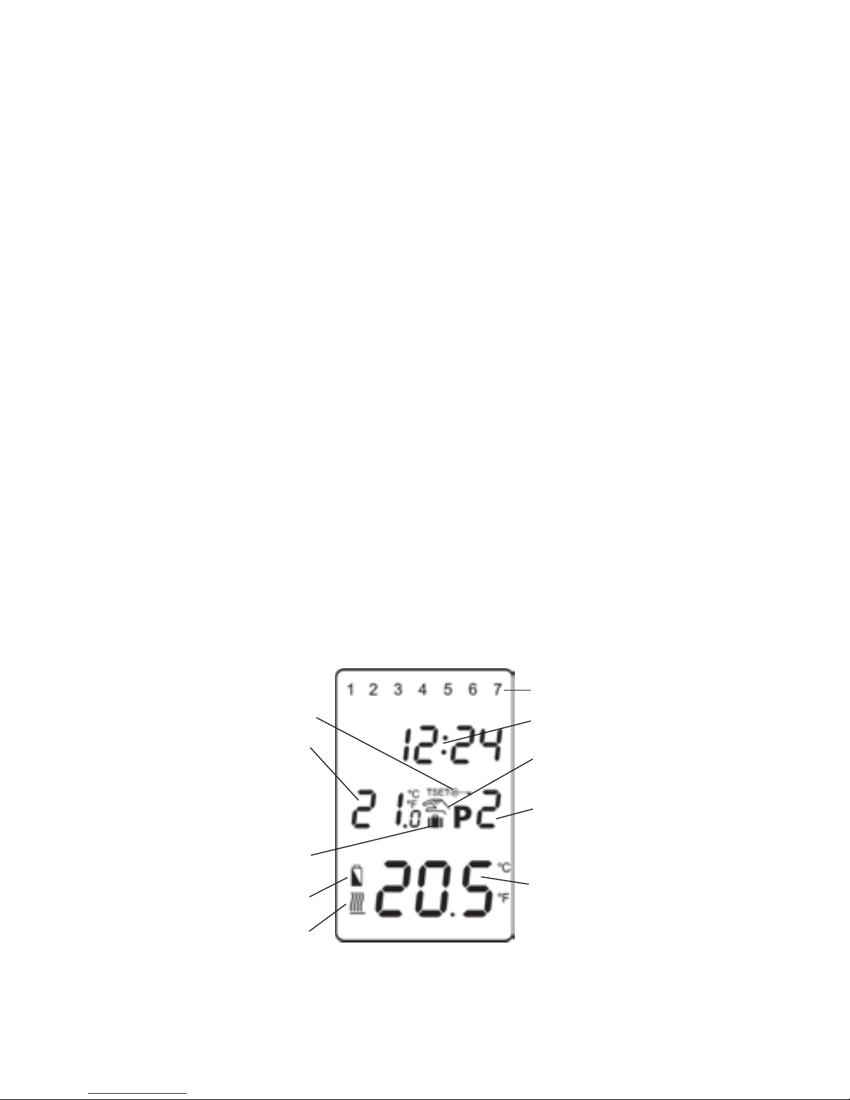
The information shown on the liquid crystal display of the
thermostat includes the following:
- 3 -
The days of the week
Time
Manual control indicator
Programme number
Current temperature
of the room
Temperature
modication until the
next manual interference
Timed manual control
indication
Low battery voltage
Sign of heating/cooling
Set temperature
Page 4
Vertical angle:
30 - 45°
Latch
1. LOCATION OF THE DEVICE
The thermostat of the
COMPUTHERM
Q7RF type device can be freely moved
in your residence. It is reasonable to locate it in a room used regularly or
for many hours per day so that it is in the direction of natural ventilation in
the room but protected from drought or extreme heat (e.g. direct sunlight,
refrigerator, chimney, etc). Its optimal location is 1.5 m above oor level. It can
be placed on its own stand or can be mounted on a wall.
IMPORTANT WARNING! If the radiator valves in your flat are equipped
with a thermostatic head, adjust it to maximum temperature or replace
the thermostatic head of the radiator valve with a manual control knob
in the room where the room thermostat is to be located, otherwise the
thermostatic head may disturb the temperature control of the flat.
2. PUTTING THE THERMOSTAT INTO OPERATION,
BASIC SETTINGS
2.1 Inserting batteries
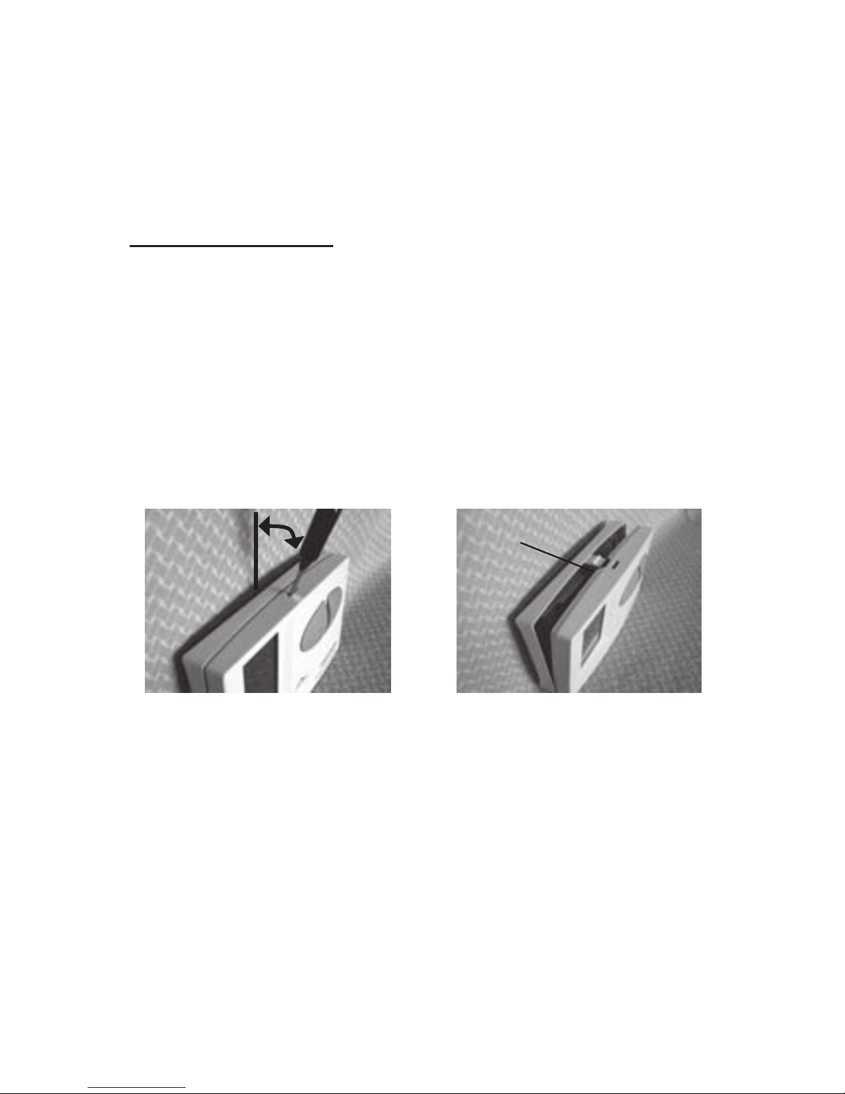
Pressing the lock on the upper side of the housing of the thermostat, remove
the back cover of the thermostat as shown in the gure below.
The battery compartment is in the inner side of the front panel of the housing.
Insert 2 AA alkaline batteries (LR6 type) in accordance with the diagram in
the battery compartment. After the batteries have been inserted, the display
ashes the day, time and program number as well as the adjusted and
measured temperatures. (If this information fails to appear on the display,
press the “RESE T” button with a wooden or plastic stick. To press the button,
do not use any electr i cally conduc t ive mater i als, e.g. graphite penc il.) After
the batteries have been inserted, snap the front panel of the device into the
rear panel and press the “ SET ” button. After the “ SET” button is pressed,
the display stops ashing, the thermostat goes to the main screen and the
setting proc e s s can be started.
- 4 -
Page 5

2.2 Setting the current day and time
Press the “SET” button to go to the main screen, then press the “DAY” button.
At this time only the serial number of the day will ash on the display of the
thermostat and the hour and minute values can be seen.
Using the large
and buttons on the front panel of the device, set the
serial number of the current day (Monday 1; Tuesday 2; Wednesday 3, etc.).
Press the “DAY” button again. At this time the number indicating the day stops
ashing and becomes visible continuously while the numbers indicating the
hour will ash on the display. Using the large and buttons on the front
panel of the device, set the hour value of the current time. Press the “DAY”
button again. At this time the numbers that indicate the hour stop ashing
and become visible continuously, while the numbers indicating the minute will
begin ashing. Using the large and buttons on the front panel of the
device, set the minute value of the current time.
When you wish to continue modifying the settings, please press the “DAY”
button again. If you wish to nish settings, conrm them by pressing the “SET”
button. At this point adjusted data are recorded and the device goes back to
the main screen (if no buttons are pressed for at least 15 seconds, the settings
are automatically conrmed and the device goes back to the main screen).
2.3 Switching between the heating and cooling mode
There is a possibility to easily switch between the heating and cooling mode
of the thermostat. The output terminals No. 1 and No. 2 of the receiver unit
are closed below the set temperature in heating mode, and they are closed
above the set temperature in cooling mode (taking the switching sensitivity
into account). The closed state of the output terminals No. 1 and No. 2 are
indicated by the icon in the bottom left corner of the display in case of both
modes.
To switch between the two modes, rst press the “SET” button to go to the
main screen. Then press the “SET” button again and hold it down and press
the “ COPY” button, too. After t his, the notice “
HE AT
” or “ ” appears in
place of the time characters, according to the selected mode. Following this,
switch between the modes using the large and buttons, then conrm
it by pressin g the “ SE T” button (if no buttons are pressed for at least 15
seconds, the setting is automatically conrmed). After this conrmation, the
device goes back to the main sc r een.
2.4 Setting the switching sensitivity (accuracy)
The switching sensitivity means the temperature difference between the
adjusted value and the actual temperature measured during the switching
process. A smaller switching sensitivity results in steadier room temperature
and therefore in higher comfort. The heat loss of the room (building) does not
depend on the switching sensitivity.
If higher comfort is needed, the switching sensitivity should be set so that it
provides a steadier room temperature. On the other hand, please also take
- 5 -
Page 6

into account that the boiler should not switch on and off multiple times in an
hour’s time except at low outside temperatures (e.g. -10°C), since the frequent
on and off switches of the boiler reduce its efciency and hence increases the
gas consumption. We recommend using the ±0.1°C switching sensitivity for
heating systems with high thermal inertia (e.g. underoor heating), the ±0.2°C
(factory default setting) and ±0.3°C switching sensitivity for heating systems
with low thermal inertia (e.g. at panel radiators).
To change the switching sensitivity, rst press the “SET ” button to go to the
main screen. Then press the “DAY” and “COPY” buttons one after the other.
Following this, select the desired switching sensitivity using the large
and
buttons. The notices “
S:1
”, “
S:2
” and “
S:3
” indicate ±0.1°C, ±0.2°C and
±0.3°C, respectively. Finally, conrm the setting by pressing the “SET” button
(if no buttons are pressed for at least 15 seconds, the setting is automatically
conrmed). After this conrmation, the device goes back to the main screen.
2.5 Activation of the pump protection function
Under the factory default settings, the pump protection function is inactive.
In order to activate or deactivate it, rst press the “SET” button to go to the
main screen. Then press the “DAY” and “PROG” buttons one after the other.
Following this, activate or deactivate this function using the large and
buttons. The notices “
HP:ON
” and “
HP:OF
” indicate activated and deactivated
state, respectively. Finally, conrm the setting by pressing the “SET” button
(if no buttons are pressed for at least 15 seconds, the setting is automatically
conrmed). After this conrmation, the device goes back to the main screen.
To prevent the pump from sticking, the activated pump protection function
switches on the boiler for a one minute period at 12:00 p.m. every day outside
the heating season. (The pump protection function can accomplish its task only
if the boiler is in working order in the summer, too. It is reasonable to set a low
temperature level, e.g. +10°C, on the thermostat for this period, to prevent the
boiler from unnecessary start-ups when the weather turns cold temporarily).
2.6 Calibrating the thermometer of the thermostat
There is a possibility to calibrate the thermometer of the thermostat (to correct
the measured temperature). In order to do this, rst press the “SET” button to
go to the main screen. Then press the “DAY” and “HOLD” buttons one after
the other. After this, the notice “ ” appears in place of the time characters,
and the correction value appears in place of the measured temperature
(
0.0
°C by default). Following this, set the desired correction value using the
large and buttons between -3.0°C and +3.0°C, in 0.1°C increments.
Finally, conrm the setting by pressing the “SET” button (if no buttons are
pressed for at least 15 seconds, the setting is automatically conrmed). After
this conrmation, the device goes back to the main screen. The correction
of the measured temperature takes effect a couple of seconds after the
conrmation.
- 6 -
Page 7

3. PROGRAMMING THE THERMOSTAT
3.1 A brief introduction to programming
• Programming means the setting of switching times and selection of
accompanying temperature levels. The device can be programmed for a
one-week period. Its operation is automatic, and it will cyclically repeat the
programs that have been keyed in. For each day, beside 1 xed switching
time, 6 adjustable switching times can be set. For all switching times a
different temperature can be assigned between 5 and 35°C, in 0.5°C
increments. The temperature set for a given switch will remain valid until
the start time of the next switch. Accordingly, the thermostat will keep the
temperature set for switching time P0 until switching time P1 is reached.
After switching time P1 the temperature selected to switch P1 will be valid
until the time of the next switch (P2).
• The start time of switch
P0
is 00:00, which cannot be changed, only its
temperature can be adjusted. So under the factory default settings, the
thermostat performs only one switch (P0) every day, which is in effect
from 00:00 until 00:00 the next day.
Note: Setting just one switch for a day (factory default setting) is reasonable
only if a constant temperature is needed all day. (For example, if for every
weekday a constant 16°C, and for every weekend a constant 22°C is
needed.) Otherwise, from both a comfort and an energy-efciency point
of view, it is recommended to activate more than one switch for each day.
Furthermore, it is advised that a comfort temperature is used only those
times, when the room or building is in use, since every 1°C decrease of
temperature saves approximately 6% energy during a heating season.
As opposed to common belief, keeping a at warm requires more energy
than heating it up. (When using a stove, more gas is needed to keep a pan
of water boiling than to just keep it warm.)
• The
P1 -P6
switches are deactivated by factory default (their start time is
--:--), but they can be activated at need. Their start time can be freely
set between 00:10 and 23:50 at 10-minute intervals given the constraint,
that their start time should be in increasing order and a difference of at least
10 minutes should be between them. This minimum 10-minute difference
is going to be preserved even if a previously activated switch is modied,
in order to avoid co-occurring or overlapping switches. In such a case,
the device automatically increases the start time of the affected switches
until a difference of at least 10 minutes between them is reached. If the
start time of a switch would be later than 23:50 because of this automatic
modication, then that switch is deactivated instead.
• In order to enter the programming mode, press the “SET ” button and
hold it down and press the “PROG” button, too. During the programming
the values being adjusted are ashing on the display. The modication
of these values can always be done using the large and buttons.
The conrmation of a value is always done by pressing the “PROG”
button, after which the next value can be adjusted. The program can be
- 7 -
Page 8
saved by pressing the “SET” button. A more detailed description of the
programming steps can be found in Section 3.3.
• If there are days, for which the same program is needed, than it is sufcient
to create that program only once, since it can be easily copied to another
day using the “COPY” button as described in Section 3.4. If the same
program is needed for every day, then there is also a possibility to create
the program of all the days together (by selecting 1 2 3 4 5 6 7 together
during the selection of days). But be aware: if the program of all the days
are created together, than their program can only be modied together.
Therefore, if a different program is needed for at least one day, then the
program of the days should be created separately, and the repeated
programs should be copied using the “COPY” button.
• A separate program can be created for the heating and cooling mode,
and these programs are preserved when switching between the modes.
Therefore, if the thermostat is used for both heating and cooling, then
there is no need to modify the program of the thermostat every time a
switch between these modes is performed.
3.2 Recommendations for creating a heating program
The average comfort needs of a person can usually be satised by a
temperature of 19-21°C during the night, and a temperature of 22-23°C during
the day. During that time of the day, when the family is at work or school, only
a lower temperature is needed. As heating up and cooling down usually takes
a long time, it is reasonable to set the start time of the switches 0.5-1 hour
before the desired time of the modied temperature. The programmability of
the thermostat provides a perfect solution for this.
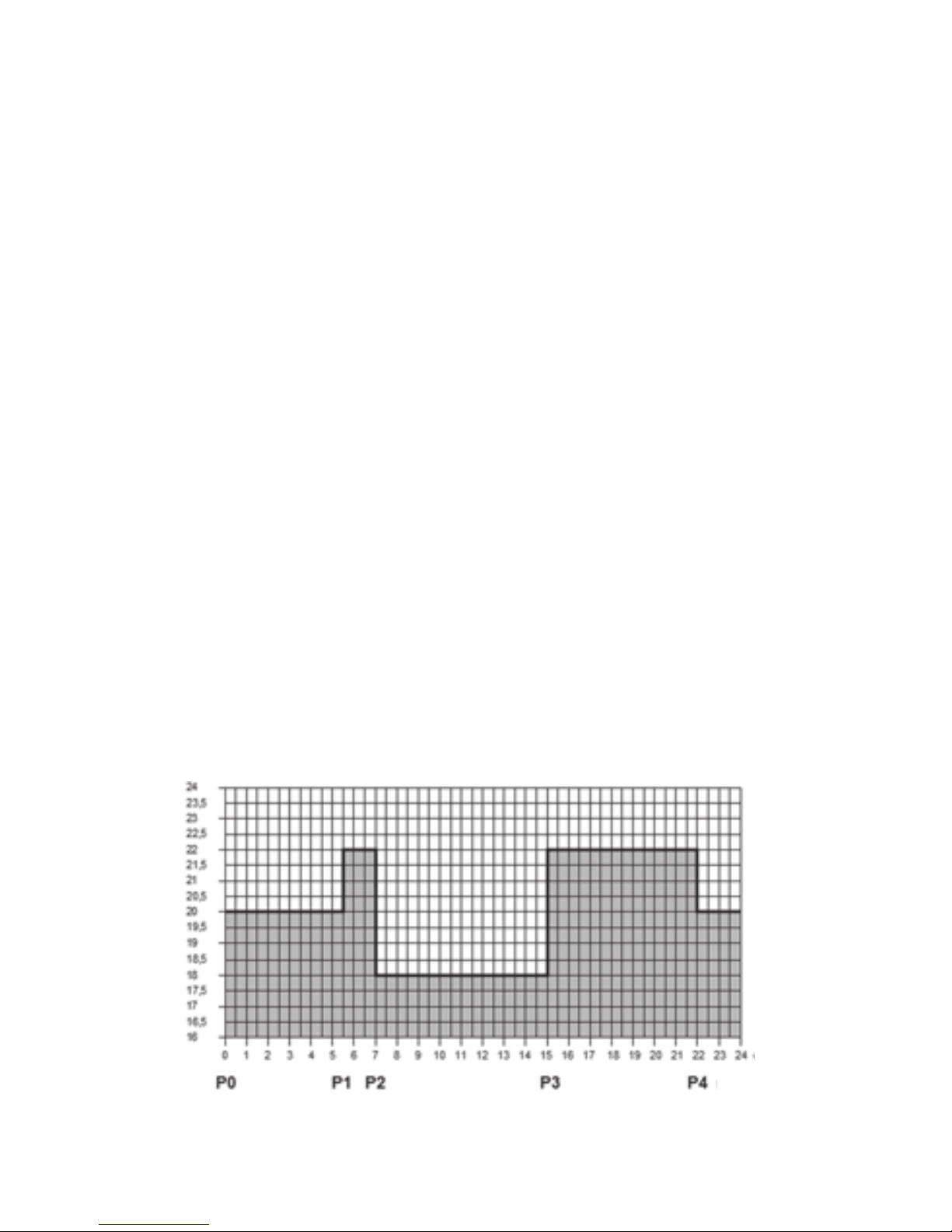
For an average working family, a program similar to the one below is
recommended:
- 8 -
Temperature
Time
00:00
20
°
C
5:30
22
°
C
7:00
18
°
C
15:00
22
°
C
22:00
20
°
C
Page 9

3.3 Programming steps
a. Press the “SET” but ton to g o to the main s c ree n.
b. Press the “SET” button again and hold it down and press the “PROG”
button, too. At this point the device gets into programming mode and the
numbers indicating the days of the week (1 2 3 4 5 6 7) are ashing on
the display.
c. Select the day to be programmed using the large and buttons on
the front panel of the device (1 indicating Monday, 2 indicating Tuesday
etc.). If you wish to create the same program for each day of the week, it
is reasonable to choose all days of the week simultaneously (by selecting
1 2 3 4 5 6 7 together), this way there is no need to perform separate
programming of the days. After selecting the desired day(s), press the
“PROG” button.
d. At this point the temperature of switch
P0
should be set, which is
indicated on the display of the device by ashing the temperature value
to be set (20 °C by default). Set the desired temperature using the large
and buttons, then press the “PROG” button.
e. Then, the start time of switch P1 should be adjusted, which is indicated on
the display of the device by ashing the time value to be adjusted (--:--
by default). Set the desired time using the large and buttons, then
press the “PROG” button.
f. Following this, the temperature of switch P1 should be set, which is
indicated on the display of the device by ashing the temperature value to
be set (20 °C by default). Set this temperature level of switch P1 using the
large and buttons, then press the “PROG” button.
g. The next step in programming is the adjustment of the start time of
switch
P2
, which is indicated on the display of the device by ashing the
time value to be adjusted (--:-- by default). The adjustment process of
switches P2-
P6
can be done (the same way as switch P1 is adjusted)
by repeating the “e”-“f” steps.
If you do not want to activate any more switches for the selected day(s),
then press the “PROG” button without changing the start time of the next
switch from the default --:--. This way the programming of the selected
day(s) is nished, the thermostat offers another day to be programmed
and the programming can be continued from step “c”.
If all the switches (P0-
P6
) are activated for the selected day(s), then after
setting the temperature value of P6, the programming of the selected
- 9 -
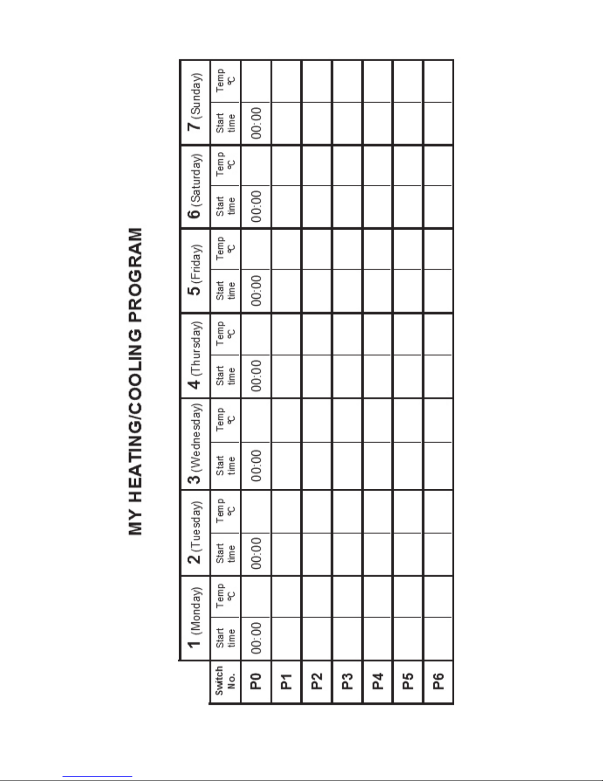
P0 00:00 20
°
C
P1 05:30 22
°
C
P2 07:00 18
°
C
P3 15:00 22
°
C
P4 22:00 20
°
C
Page 10

day(s) is nished, the thermostat offers another day to be programmed
and the programming can be continued from step “c”.
h. The adjusted program can be saved by pressing the “SET” button. After
approximately 1 minute, the adjusted program is automatically saved.
Afterwards, the device goes back to the main screen.
If you wish to copy the program of the day(s) selected in step “c” to other days, you
can easily do so using the “COPY” button as described in Section 3.4.
3.4 Using the „COPY” function (Copying the program of a day to other days)
• First, press the “SET” button to go to the main screen. Then press the
“COPY” button for approximately 3 seconds to activate the “COPY”
function. The notice “
Copy
” appearing in place of the time characters and
the ashing serial number 1 indicating Monday shows that conditions are
ready for copying a program.
• Select the day whose program you wish to copy to another day or other
days using the large and buttons on the front panel of the device.
• Press the “COPY” button to copy the program of the selected day. After
this, the ashing of the number indicating the day that has been copied
stops and it will be visible continuously hereafter.
• Select the day to which you wish to copy the program of the day copied
beforehand using the large and buttons. The number of the active
day is ashing during this selection process.
• After selecting the number that indicates the day to which you wish to copy
the program, press the “COPY” button to copy the program. Hereafter, the
number indicating the day to which the program was copied will be visible
continuously. Following this, you can select further days using the large
and buttons and copy the program to those days too by pressing
the “COPY” button.
• Finally, press the “SET” button to save the modications (if no buttons are
pressed for at least 15 seconds, the modications will be automatically
saved). Afterwards, the device goes back to the main screen. If required,
the program of further days can be freely copied by repeating the above
steps.
ATTeNTION! The “COPY” function is only available, if the days of the week
were programmed separately!
3.5 Modifying the program
• The previously set program can be modied any time by repeating the steps
of programming.
• The number of activated switches can be increased at will as described in
Section 4.3.
• A previously activated switch can be deactivated by setting its start time to
--:-- using the large and buttons (or by pressing the “DAY” button
once), and then pressing the “PROG” button. After this, if the deactivated
- 10 -
Page 11

switch was an intermediate one, then the serial numbers of the remaining
switches will be updated.
• If you wish to nish modifying the program of the selected day, then press
the “PROG” button and hold it down for at least 3 seconds. After this, the
modication can be continued by selecting another day. When nished
with all the modications, press the “SET” button to save them. After
approximately 1 minute, they are automatically saved. Afterwards, the
device goes back to the main screen.
• If a completely different program is needed, then press the “R ESE T ”
button to reset the device (it de letes both th e pro gram and t he basic
settings). To press the button, do not use any electrically conductive
materials, e.g. graphite pencil. Following this, adjust the basic settings
of t he thermo stat again and cre ate the new program, as de scr ib ed in
Sections 2 and 3.
3.6 Program inspection
• First, press the “SE T” button to go to the main screen, then press the
“PROG” button. At this point, the serial number indicating the day(s), the
symbol of switch P0 and the time and temperature level set for switch
P0
of the selected day(s) will appear on the display (none of the values
is ashing).
• Repeatedly press the “PROG” button to check the values of switch P2, P3,
etc. Use the large and buttons to change the day(s). If all the days
were programmed together (1 2 3 4 5 6 7), then their common program can
only be viewed together .
• After checking the program, press the “SET” button to go back to the main
screen (if no buttons are pressed for at least 15 seconds, the thermostat will
automatically go back to the main screen).
4. TEMPORAR Y MODIFICA TION OF THE TEMPERATURE
CORRESPONDING TO THE PR OGRAM
If you wish to operate your device in a way that differs temporarily from the
program that has been set (e.g. on bank holidays or the winter holidays), you
can choose among the options described in Sections 4.1-4.4.
To simplify manual temperature modications, with factory default settings
temperatures of
18°C and 22 °C are assigned to the large and buttons,
respectively. When modifying the temperature manually, pressing the or
button once, the temperature will immediately jump to the factory value
of the button. For example, if the current switch P3 ensures a temperature of
19°C, it can be modied to a standard temperature that ensures 22°C when
needed by pressing the button only once, without having to press the
button several times in increments of 0.5°C. Following this, using the large
and buttons, the temperature can be further modied in increments of
0.5°C, in accordance with current requirements.
- 11 -
Page 12

The economy and comfort temperature values assigned to buttons and
can be modied as follows:
• To set the economy temperature, press the “SET” button and keep it
depressed and press the button, too. Following this, with the help of
the and buttons, set the economy temperature selected by you.
After the temperature has been set, press the “SET” button to save the
modication (after approximately 15 seconds, it is automatically saved).
Afterwards, the device goes back to the main screen.
• To set the comfort temperature, press the “SET” button and keep it
depressed and press the button, too. Following this, with the help of
the and buttons, set the comfort temperature selected by you.
After the temperature has been set, press the “SET” button to save the
modication (after approximately 15 seconds, it is automatically saved).
Afterwards, the device goes back to the main screen.
4.1 Temperature modication until the next program switch
Set the required temperature using the large and buttons on the
front panel of the device. At this time, the icon appears on the display,
indicating that the thermostat is operated with manual control. The device
will control the boiler according to the set value until the time of the next
switch specied in the program is reached.
During this temporary modication, the segments indicating the time on the
display alternately show the exact time and the time remaining in manual
control (e.g.
1H:02
, that is, 1 hour and 2 minutes). After this time has elapsed,
the icon disappears and the device resumes the program that has been
set. If you wish to return to the set program before the time of the next switch
is reached, please press the “SET” button.
4.2 Temperature modication for 1-9 hours (party program)
Set the required temperature using the large and buttons on the
front panel of the device, and then press the “DAY” button. At this time,
the icon appears on the display, along with number 1 in place of the
switch number, which indicates the duration of modication in hours. Adjust
this time to the desired length (between 1 and 9) using the large and
buttons. The party program will start approximately 10 seconds after the
adjustment. Following this, the device will keep the modied temperature for
the given period of time. The adjusted temperature can be freely changed
during the party program without exiting it.
During this temporary modication, the segments indicating the time on the
display alternately show the exact time and the time remaining in manual
control (e.g.
3H:02
, that is, 3 hours and 2 minutes). After this time has
elapsed, the icon disappears and the device resumes the program that
has been set. If you wish to return to the set program before the time set for
temperature modication has expired, please press the “SET” button.
- 12 -
Page 13

4.3 Temperature modication for 1-99 days (holiday program)
Set the required temperature using the large and buttons on the front
panel of th e device, and then press the “ H O LD ” button and hold it down
for at least 2 secon ds. At thi s time, the icon appears on t he display,
along with the
P
:01
notice in place of the time characters, which indicates
the duration of modication in days. Adjust this time to the desired length
(between 1 and 99) using t he large and buttons (1 day means 24
hours). Th e holiday progra m will start approximately 10 s econds af ter the
adjustment. Following this, the device will keep the modied temperature for
the given period of time. The adjusted temperature can be freely changed
during the holiday program without exiting it.
During this temporary modication, the segments indicating the time on the
display alternately show the exact time and the days remaining in manual
control (e.g.
P
:03
, that is, 3 days). A fter this t ime has elapsed, the
icon disappears and the device resumes the program that has been set.
If you wish to return to the set program before the time set for temperature
modication has expired, please press the “SET ” button.
4.4 Temperature modication until the next manual interference
Set the required temperature using the large and buttons on the
front panel of the device. At this time, the icon appears on the display,
indicating that the thermostat is operated with manual control. Then, press the
“HOLD” button briey, after which the icon appears and the icon
disappears. The device will then control the boiler according to the set value
until the next manual interference. During this time, the thermostat acts exactly
the same way as a non-programmable thermostat. The adjusted temperature
can be freely changed during this temporary modication without exiting it.
If you wish to return to the set program, please press the “SET” button.
5. TURNING ON THE BACKGROUND LIGHT
When you press the “LIGHT” button, the background light of the display will
turn on for 15 seconds. When you press another button while the display
is illuminated, the background light will turn off only after 15 seconds have
elapsed since the last button had been pushed.
6. LOCKING THE CONTROL BUTTONS
The thermostat enables you to lock its control buttons. With this function, you
can prevent unauthorised modication of the program or the set temperature.
To activate the lock, rst press the “SET ” button to go to the main screen,
then press the and buttons together and hold them down for at least 5
seconds. After the control buttons have successfully been locked, the notice
“ ” appears in place of the time characters for a couple of seconds. Until
the control buttons are locked, their normal function do not work; if any button
is pressed, then only the notice “ ” appears and nothing else happens. To
- 13 -
Page 14

- 14 -
unlock press the and buttons together and hold them down for at least
5 seconds. After unlocking the buttons, the notice “ ” appears in place
of the time characters for a couple of seconds, whereupon all the buttons can
be used normally again.
7. CHANGING THE BATTERY
The average lifetime of the batteries is 1 year, but frequent use of the
background light may shorten this time considerably. If the icon indicating
low battery voltage appears on the display, the batteries should be replaced
(see Section 2.1). The exact time should be set again after the batteries have
been replaced, but the device saves the program that has been loaded even
without batteries therefore there is no need to reprogram the device.
8. RESETTING THE THERMOSTAT TO ITS FACTORY
DEFAULT SETTINGS
By pressing the “RESET” button, the thermostat can be reset to its factory
default settings. This results in deleting the day, exact time, basic settings
and the set program. To press the “RESET” button, do not use any electrically
conductive materials, e.g. graphite pencil. After resetting the device, adjust
the basic settings of the thermostat again and create the new program, as
described in Sections 2 and 3.
9. THE RECEIVER UNIT
9.1 Installation and connection of the receiver unit
The receiver unit should be mounted on the wall in a place protected against
moisture and heat, in the vicinity of the boiler.
ATTeNTION! Do not install the receiver unit under the housing of the boiler or
near hot pipes because it may damage the parts of the device or compromise
wireless (radio-frequency) connection. To avoid electric shock, entrust a
specialist with connecting the receiver unit to the boiler!
Unscrew the two screws at the bottom of the receiver unit without removing
them. Following this, remove the front panel of the receiver unit then x the
back panel to the wall in the vicinity of the boiler with the screws provided.
Remove the protective carton from the contacts to ensure perfect contact. The
marks of the connections are pressed into the plastic above the connection
points: N, L, 1, 2 and 3.
230V mains voltage should be supplied to the receiver unit. This provides the
power supply for the device, but this voltage does not appear on the terminals
1 and 2. We propose to connect the neutral wire of the network to point N, while
the phase conductor to point L. We recommend using a fork type connection
including a switch for mains connection. Please de-energize the device when
heating is continuously not needed (e.g. summer).
Page 15
- 15 -
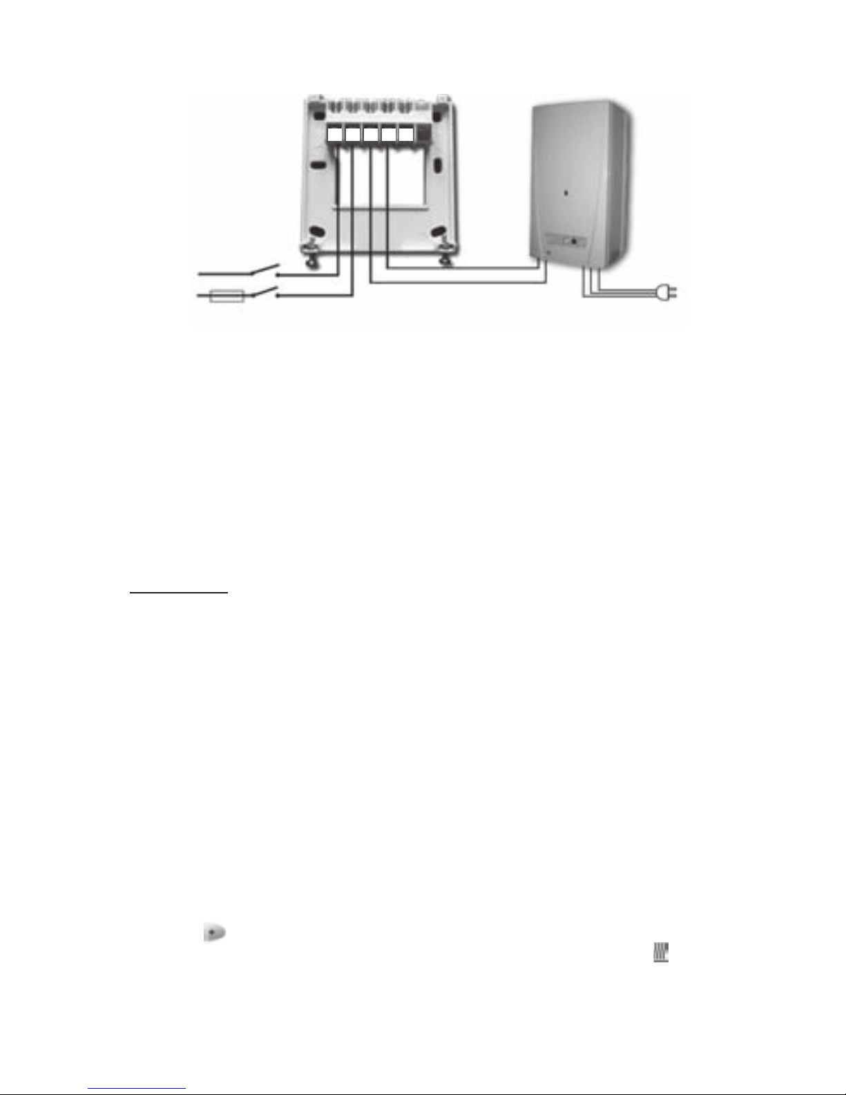
The receiver unit controls the boiler or air conditioner through a potential-free
alternating relay whose connection points are: 1 (NO), 2 (COM) and 3 (NC).
Connect the two connection points of the heating or cooling equipment to be
controlled to terminals No. 1 (NO) and No. 2 (COM), i.e. to the normally open
terminals of the relay.
If you would like to operate an old boiler or any other device that has no
connection points for thermostats, then the No. 1 (NO) and No. 2 (COM)
connection points of the thermostat should be connected to the mains cable
of the device, similarly as a switch would be connected.
ATTeNTION! Always consider the loadability of the receiver unit and follow the
manufacturer’s instructions of the heating or cooling equipment. The device must
be installed and connected by a qualied professional!
The voltage appearing at terminals No. 1 and No. 2 depends only on the
system being controlled, therefore the dimensions of the wire are determined
by the type of the device to be controlled. The length of the wire is of no
signicance, the receiver unit may be installed either near the boiler or far
away from it, but do not install it under the housing of the boiler.
If the distance between the transmitter and receiver units is too large due to
local circumstances and it makes the wireless (radio-frequency) connection
unreliable, install the receiver unit nearer to the place of thermostat.
9.2 Putting the receiver unit into operation
Turn on the power supply to the receiver unit. After a few seconds have
elapsed, the wireless (radio-frequency) system (thermostat and receiver unit)
tunes itself to the operating frequency. To try the system in heating mode,
press the button of the thermostat several times, until the set temperature
is 2-3°C higher than the temperature of the room. Following this, the icon
indicating that the heating is turned on should appear on the display of the
thermostat within a few seconds. At the same time, the red LED light on the
Heating unit (boiler)
Rear panel of
the receiver
unit
N
L
(phase)
230V AC
50-60 Hz
230V AC
50-60 Hz
LN 1 2 3
COM
NO NC
Page 16

- 16 -
receiver unit should switch on to indicate that the receiver unit has received
the command of the transmitter (thermostat).
If it does not happen, the system should be retuned. For this purpose press
the “M/A” button of the receiver unit and keep it depressed (for approximately
10 seconds) until the green LED starts ashing. After this, press the “SET”
button of the thermostat and keep it depressed then press the “DAY” button of
the thermostat and keep it depressed too (for approximately 10 seconds) until
the green LED stops ashing and goes out, so that the receiver unit “learns”
the safety code of the transmitter (thermostat). The safety code will not be lost
even during a power outage, the device memorizes it automatically.
ATTeNTION! Pressing the “SeT” and “DAY” buttons simultaneously for 10
seconds generates a new safety code for the thermostat, and the receiver will
recognize it only after a repeated tuning. With this in mind, do not keep the
“SeT ” and “DAY” buttons of the thermostat depressed simultaneously or the
“M/A” button of the receiver unit depressed without any reason after the two
units have been tuned successfully.
9.3 Transmission distance inspection
With the help of t he “TEST” button you can check whether the two units
are within the transmi s si on distance of the radiofrequency connecti on. To
perfo rm t he test, press the “TEST ” button for approximately 2 seconds.
Following this, the therm ost at will send, alternating every 5 seco nds, switchon and switch- off control signals to the receiver for 2 minutes (the signal
appears and disappears alternately on the display). When detecting the ON
and OFF control signals, the red LED light on the receiver unit switches on
and off, resp ectively. When t he receiver unit fails to r eceive signals sent by
the thermostat, then the receiver unit is outside the transmission distance
of the wireless (radio-frequency) transmitter, thus they have to be placed
closer to each other.
9.4 Manual control of the receiver unit
Pressing the “MANUAL” button separates the thermostat from the receiver
unit. In this case, the boiler or air conditioner connected to the receiver unit
can only be turned on and off manually, without any temperature inspection.
The continuously illuminated green LED indicates “MANUAL” mode. Pressing
the “M/A” button turns on or off the boiler. (The red LED is illuminated when
the boiler is turned on). By pressing the “MANUAL” button again, the device
quits manual control and resumes automatic (thermostat-controlled) operation
(the green LED goes out).
Page 17
- 17 -
Page 18

- 18 -- 18 -
TECHNICAL DATA
Technical data of the thermostat (transmitter):
— temperature measurement range: 5 to 35°C (in 0.1°C increments)
— adjustable temperature range: 5 to 35°C (in 0.5°C increments)
— temperature measurement accuracy: ±0.5°C
— temperature calibration range: ±3°C (in 0.1°C increments)
— selectable switching sensitivity: ±0.1°C; ±0.2°C; ±0.3°C
— storage temperature: -10°C to +40°C
— battery voltage: 2 x 1.5V ALkALINE batteries (LR6 type; AA size)
— power consumption: 1.3mW
— battery lifetime: approx. 1 year
— operating frequency: 868.35MHz
— dimensions: 130 x 80 x 35mm (without holder)
— weight: 154g
— temperature sensor type: NTC 10kΩ ±1% at 25°C
Technical data of the receiver unit:
— power supply voltage: 230V AC, 50Hz
— power consumption: 6W
— switchable voltage: 24V AC/DC to 250V AC, 50Hz
— switchable current: 6A (2A inductive load)
— transmission distance: approx. 50m in open terrain
— weight: 150g
Total weight of the device: approx. 500g (thermostat+receiver+holder)
Page 19

A brief description of progrAmming
• Setting the date and time: press the “DAY” button, then adjust values using the
“DAY”,
and buttons.
• Programming: press and hold down the “SET” button, while pressing the
“PROG” button too, then adjust values with the “PROG”,
and buttons;
use the “COPY” button to copy repeated programmes.
• Program inspection: using the “PROG”, and buttons.
• Retuning: using the “M/A”, “SET” and “DAY” buttons (see Section 9.2).
• Transmission distance control: press the “TEST” button for more than 2
seconds.
• Temporary modication of the temperature set in the program:
until the next switch in the program• : set the temperature using the
and
buttons.
for a period of 1 to 9 hours• : set the temperature using the
and
buttons, then press the “DAY” button, and nally set the duration using the
and buttons.
for a period of 1 to 99 days• : set the temperature using the
and
buttons, then press the “HOLD” button and hold it down for 2 seconds, and
nally set the duration using the
and buttons.
until the next interference• : set the temperature using the
and buttons,
then press the “HOLD” button briey.
 Loading...