

Page 1
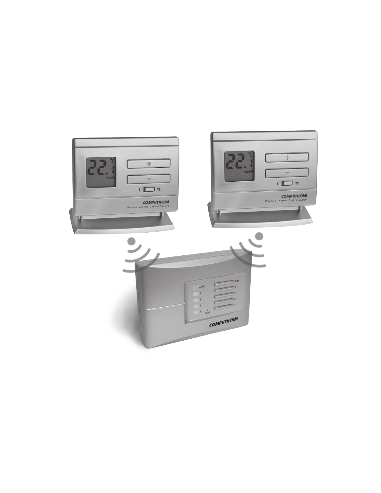
COMPUTHERM
Q5RF
Multi-zone wireless
(radio-frequency)
digital room thermostat
Operating instructions
You can watch the most important aspects of the usage of this thermostat on our video
presentation at www.quantrax.hu.
Page 2

Page 3
- 3 -
GENERAL DESCRIPTION OF THE THERMOSTAT
The
COMPUTHERM
Q5RF type switched-mode room thermostat is suitable
to regulate the overwhelming majority of boilers and air conditioners. It can
easily be connected to any gas boiler or air conditioning device that has a
double wire connector for a room thermostat, regardless of whether it has a
24 V or 230 V control circuit.
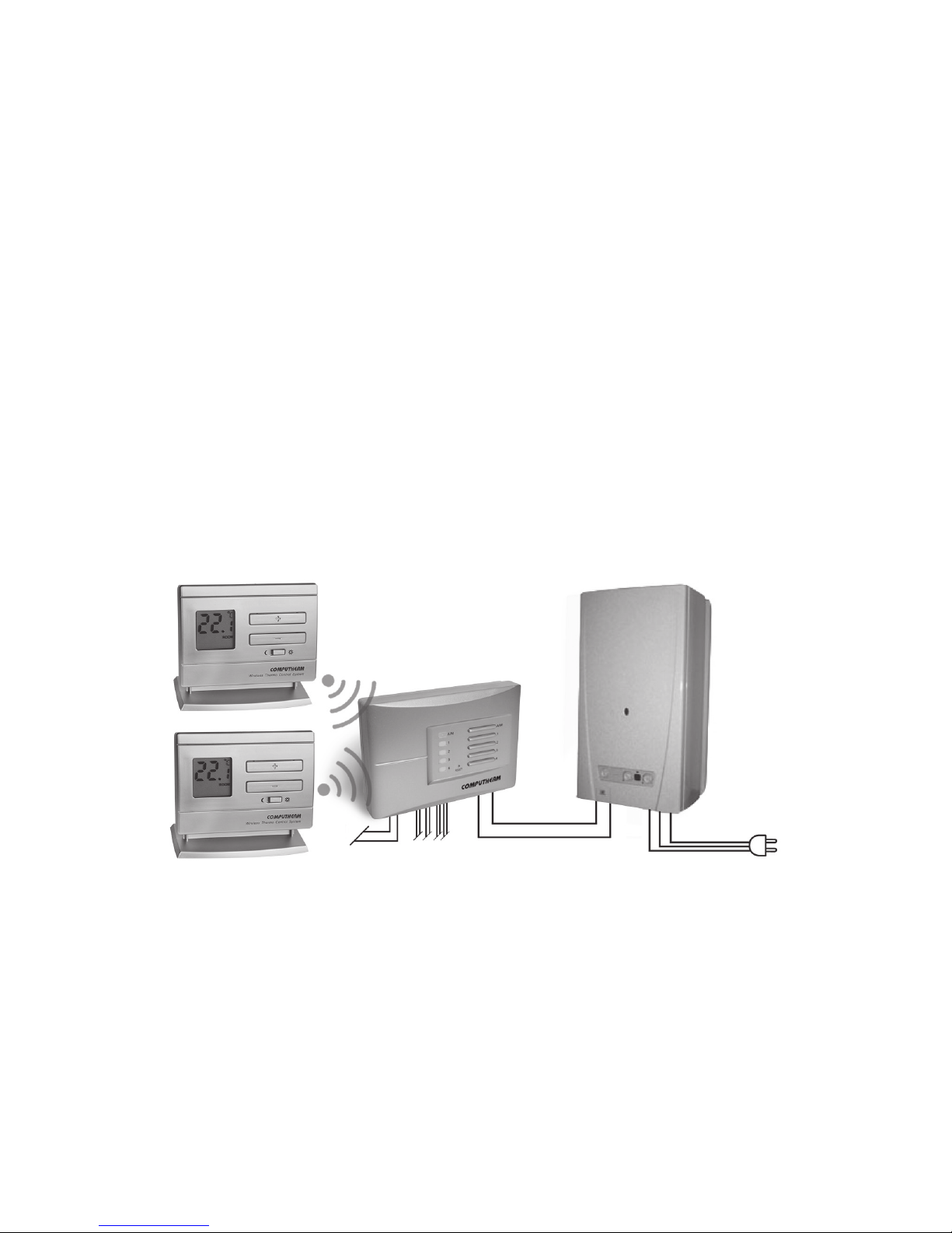
The basic package of the device includes two thermostats and a receiver unit.
If required, the equipment can be extended by two additional
COMPUTHERM
Q5RF (TX) or Q8RF (TX) thermostats. The receiver unit receives switching
signals from the thermostats, controls the boiler (or air conditioner) and
gives commands to open/close the heating zone valves (max. 4 zones,
loadability of the zone outputs: 230 V AC, max. 1 A (0.5 A inductive load))
associated with the thermostats. The zones can operate independently from
each other or, in case of need, all zones can operate at the same time.
This way only those rooms are heated at a given time, where it is required
(e.g. the living room and the bathroom during the day, and the bedroom
during the night). Because there is a wireless (radio-frequency) connection
between the thermostats and the receiver, no cable is required between the
thermostats and the boiler. The installation and connection of the receiver
unit is described in Section 7.
Temperature can be measured and set more precisely as compared to
simple, conventional thermostats. In heating mode, in accordance with the
selected switching sensitivity, the thermostat switches the boiler or any
other appliances on and o below and above the adjusted temperature,
respectively, and contributes to reduce energy costs while maintaining
comfort. In cooling mode it switches exactly the opposite way.
To increase the lifetime of the batteries, the thermostat will not transmit
signals continuously. Instead it will repeatedly transmit the actual signal
every 5 minutes. Therefore, the regulation of the heating or cooling will
continue even after a blackout.
- 3 -
Thermostats
Boiler
Reciever
230 V AC, 50-60 Hz
Zone valves
230 V AC, 50-60 Hz
Page 4
- 4 -
The portability of the thermostat oers the following advantages:
• no need to lay a cable, which is especially advantageous when old
buildings are being modernized,
• the optimal location of the device can be selected during operation,
• it is also advantageous when you intend to locate the thermostat in
dierent rooms in the course of the day (e.g. in the living room during
the day but in the bedroom at night).
The eective range of the transmitter incorporated in the thermostat is approximately 50 m in open terrain. This distance may become considerably shorter
within a building, especially when a metal structure, reinforced concrete or adobe
wall stands in the way of radio waves.
The switching sensitivity of the thermostat can be set to ±0.1 °C or ±0.2 °C (de-
fault setting). This means the dierence between the adjusted temperature and
the actual temperature measured during the switching process.
In case of the ±0.2 °C switching sensitivity and heating mode for example, if the
set temperature is 20 °C, then the device switches the boiler on at 19.8 °C or
below, and switches it o at 20.2 °C or above. Please refer to Section 3.2 for the
modication of the factory default switching sensitivity of ±0.2 °C.
This wireless (radio-frequency) thermostat can also be easily extended with the
COMPUTHERM
Q1RX socket if needed, with which the thermostat is able to control boilers or any other electrical devices operating on 230V (50Hz; max. 16A)
(e.g. fan heaters, pumps, zone valves, etc.) according to the room temperature.
(You can nd detailed information and recommended usage of the
COMPUTHERM
Q1RX socket on our website: www.quantrax.hu)
1. LOCATION OF THE DEVICE
The thermostat of the
COMPUTHERM
Q5RF type device can be freely moved in
your residence. It is reasonable to locate it in a room used regularly or for many
hours per day so that it is in the direction of natural ventilation in the room but protected from drought or extreme heat (e.g. direct sunlight, refrigerator, chimney,
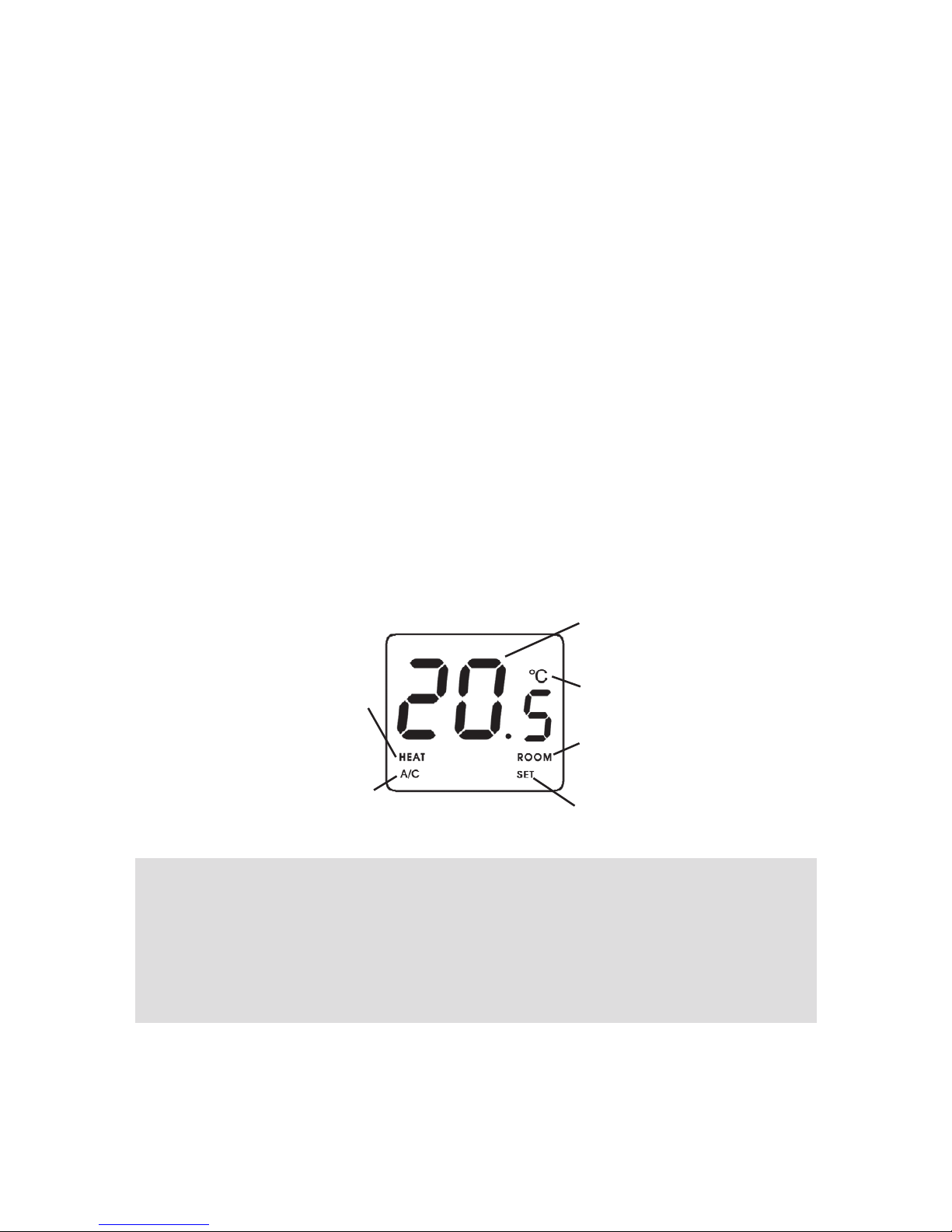
Temperature
Temperature
measurement unit
Room temperature
is displayed
Set temperature
is displayed
Sign of the
boiler working
Sign of the air
conditioner
working
The information shown on the liquid crystal
display of the thermostat includes the following:
- 4 -
Page 5
- 5 -
etc). Its optimal location is 1.5 m above oor level. It can be placed on its own
stand or can be mounted on a wall.
IMPORTANT WARNING!
If the radiator valves in your at are equipped
with a thermostatic head, adjust it to maximum temperature or replace the
thermostatic head of the radiator valve with a manual control knob in the
room where the room thermostat is to be located, otherwise the thermo-
static head may disturb the temperature control of the at.
2. PUTTING THE THERMOSTAT INTO OPERATION
The device must be installed and connected by a qualied professional.
Warning! Modifying the thermostat can cause electric shock or product
failure.
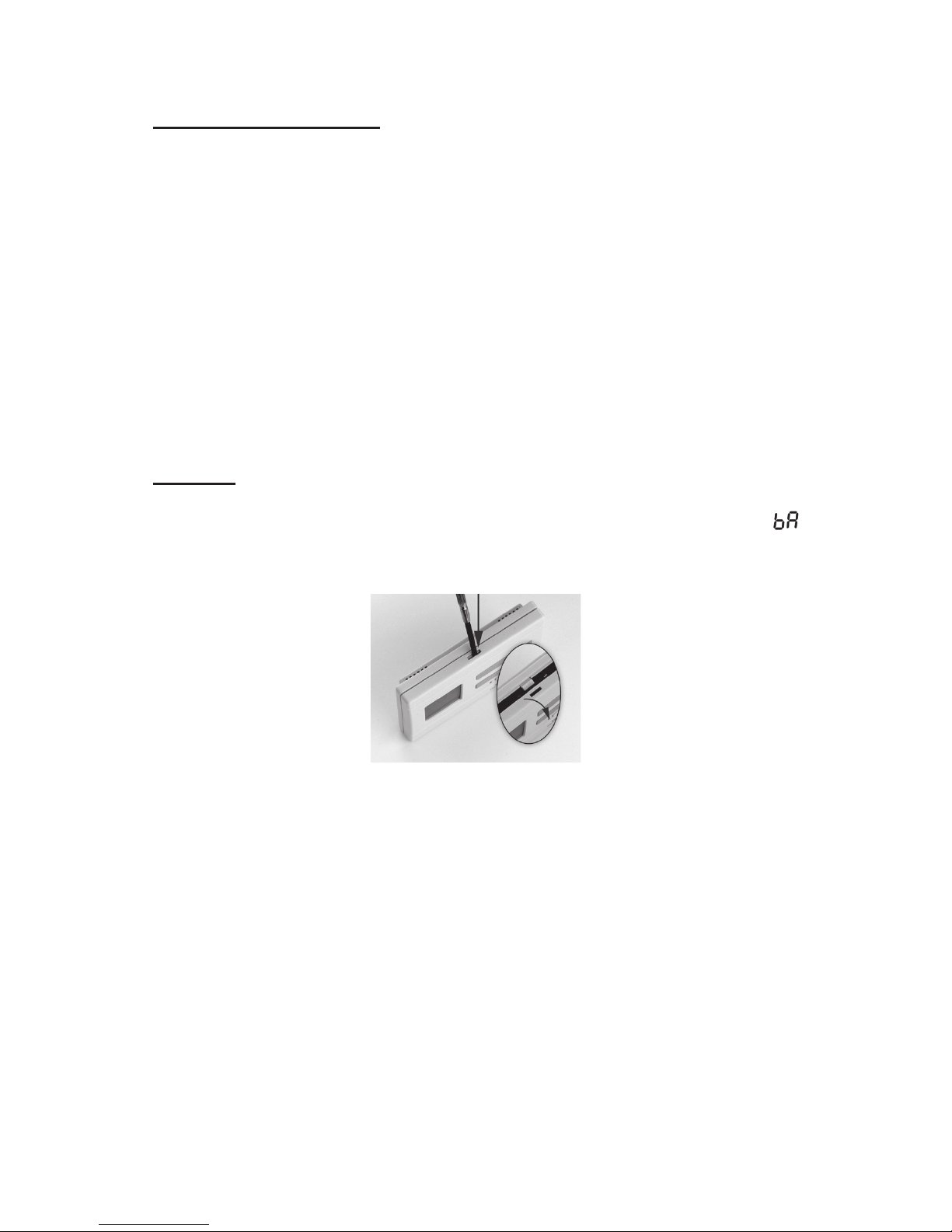
To put the thermostat into operation, detach the rear panel of the thermostat
from the front panel by pressing the lock on the upper side of the housing of
the thermostat, as shown in the gure.
Warning! Alkaline batteries may only be used for this appliance. Car-
bon-zinc batteries known as durable or long life batteries and chargeable
accumulators are not suitable for the operation of this appliance. Icon
appearing on the display to indicate low battery voltage warns reliably that
the batteries should be replaced only when alkaline batteries are used.
After the batteries have been inserted, the display ashes the measured
room temperature. (If this information fails to appear on the display, press
the „RESET” button located on the main panel of the thermostat.
3. BASIC SETTINGS
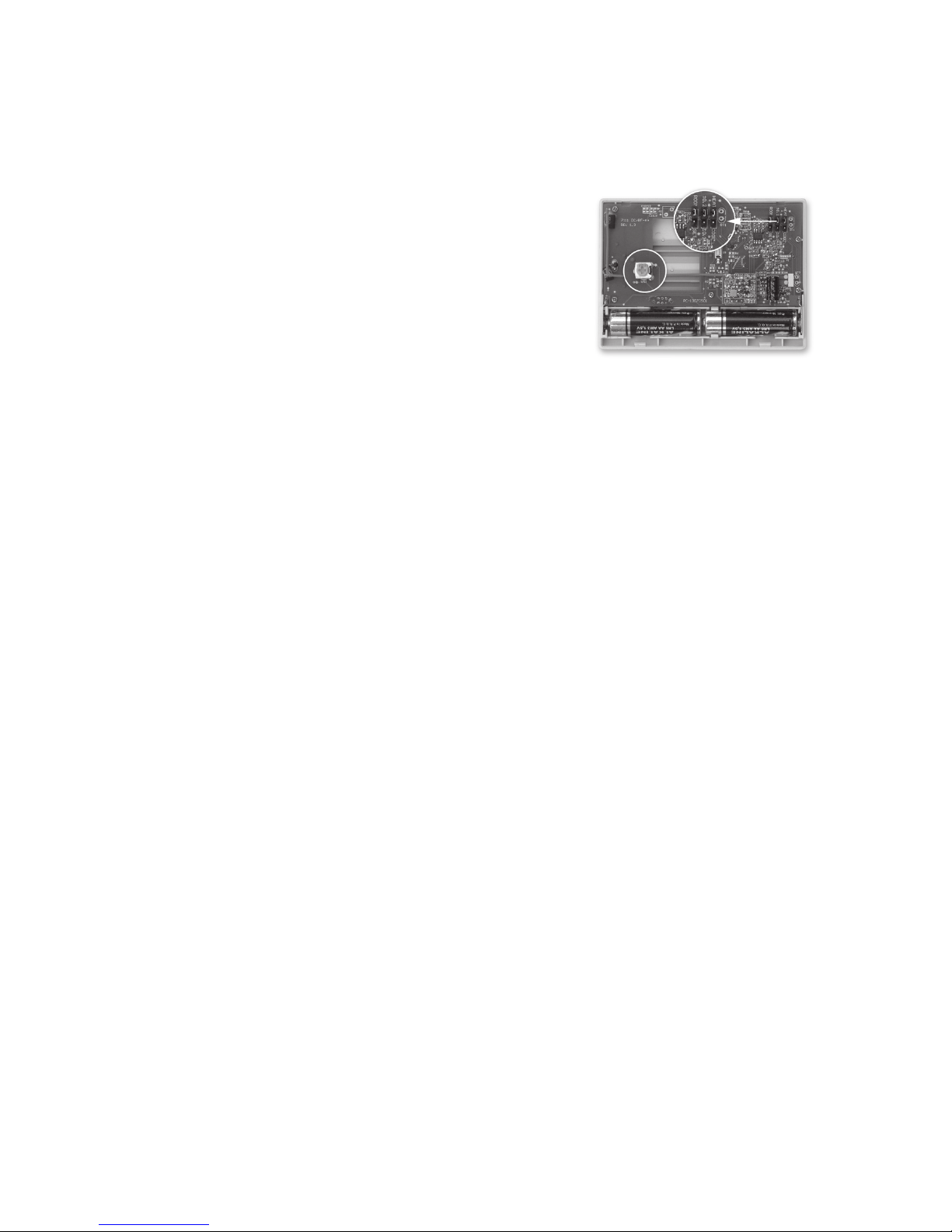
After removing the rear panel of the device, the following factory default
settings can be modied by relocating the jumpers (black plugs) and/or
changing the position of the orange-colored potentiometer located on the
main panel.
3.1 Selecting the Displayed Temperature
The temperature(s) to be shown on the display can be selected and set
by the left jumper.
With factory default settings the jumper is located on the central and
uppermost pins, in which case the display shows the currently measured
- 5 -
Page 6
- 6 -
room temperature value, while the notice “ROOM” appears in the bottom
right corner of the display. In this case, the adjusted temperature is visible
only during the adjustment process, for approximately 7 seconds after the
last button has been pushed. By relocating the plug onto the bottommost
and central pins the displayed temperature can be modied so that the
display alternately shows the current room
temperature and the adjusted temperature for 4
seconds, respectively. In this mode, the notices
“ROOM” and “SET” are alternately shown
under the currently displayed temperature
in the bottom right corner of the display,
indicating whether the display shows the room
temperature or the adjusted temperature value.
3.2 Selecting the Switching Sensitivity (Accuracy)
The switching sensitivity of the thermostat can be selected or adjusted
by the central jumper.
With factory default settings the jumper is located on the central and
uppermost pins, resulting in a switching sensitivity of ±0.2 °C. It can
be modied to ±0.1 °C by relocating the jumper onto the bottommost
and central pins. A smaller switching sensitivity results in steadier room
temperature and therefore in higher comfort. The heat loss of the room
(building) does not depend on the switching sensitivity.
If higher comfort is needed, the switching sensitivity should be set so
that it provides a steadier room temperature. On the other hand, please
also take into account that the boiler should not switch on and o multiple
times in an hour’s time except at low outside temperatures (e.g. -10 °C),
since the frequent on and o switches of the boiler reduce its eciency
and hence increases the gas consumption. We recommend using the
±0.1 °C switching sensitivity for heating systems with high thermal inertia
(e.g. underoor heating), and the ±0.2 °C switching sensitivity (factory
default setting) for heating systems with low thermal inertia (e.g. at panel
radiators).
3.3 Switching between the Heating and Cooling Mode
The heating or the cooling mode of the thermostat can be selected by the
right jumper.
With factory default settings the jumper is located on the central and
uppermost pins, which selects the heating mode. By relocating the jumper
onto the bottommost and central pins, the cooling mode can be selected.
The output terminals No. 1 (NO) and No. 2 (COM) of the receiver unit
are closed below the set temperature in heating mode, and they are
closed above the set temperature in cooling mode (taking the switching
sensitivity into account). The closed state of the output terminals No. 1
(NO) and No. 2 (COM) are indicated by the notice „HE AT ” (heating) or
- 6 -
Page 7
- 7 -
„A/C” (cooling) in the bottom left corner of the display, according to the
selected mode.
3.4 Calibration of the thermometer of the thermostat
You can calibrate the thermometer of the appliance (to correct measured
temperature). To this end all you have to do is change the position of the
orange-colored potentiometer by a Phillips screwdriver. When you adjust
the potentiometer clockwise then the displayed temperature will be higher
than that measured initially, and when you adjust it anticlockwise the
displayed temperature will be lower than that. The displayed temperature
can be adjusted within a range of approx. 3 °C.
Correction of the displayed temperature takes place a few seconds after
the adjustment.
ATTENTION! If the modication of the basic settings was done after insert-
ing the batteries and the modications did not take eect, please press the
“RESET” button located on the main panel of the thermostat.
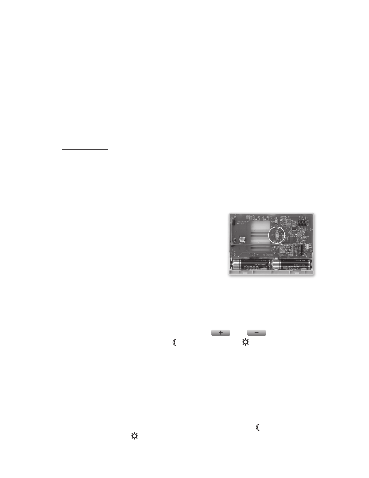
3.5 Synchronising the Thermostat and the Receiver Unit
In order to have a safe, reliable and trouble-free wireless (radio-frequency) connection, both the thermostat and the receiver unit have their own
safety codes. After installing the receiver unit,
the two units should be synchronised by pressing the “LEARN” button located above the
battery compartment, on the main panel of the
thermostat. Therefore do not replace the rear
panel of the thermostat onto the front panel before synchronisation. The process of synchronisation is described in Section 7.2.
4. SETTING THE DESIRED TEMPERATURE
After putting the thermostat into operation and adjusting the basic settings
the thermostat is ready for operation and the adjustment of the temperature
can be started.
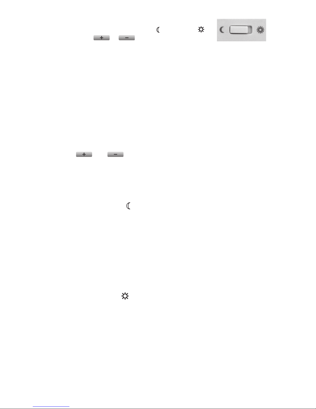
Below the temperature adjustment buttons ( and ) a switch is
located. For both the economy (w) and the comfort (☼) positions of the
switch a dierent temperature can be set between 5 °C and 40 °C, in
steps of 0.5 °C.
For energy eciency it is recommended that the comfort temperature is
only used those times, when the room or building is in use, because every
1 °C decrease of temperature saves approximately 6% energy during a
heating season. As opposed to common belief, keeping a at warn requires
more energy than heating it up. (When using a stove, more gas is needed to
keep a pan of water boiling than to just keep it warm.)
The factory default temperature is 18 °C for the economy (w) position and
20 °C for the comfort (☼) position. These default temperatures can be changed
as follows:
- 7 -
Page 8
- 8 -
• Move the switch according to the temperature you
would like to change (economy (w) or comfort (☼)).
• Press the or button, after which the no-
tice “ROOM” disappears, the notice “SET” (adjusted
value) appears in the bottom right corner of the display. Meanwhile,
the temperature value shown on the display switches from room temperature to the default temperature (18.0 °C/20.0 °C) or to the last set
temperature (this temperature is blinking on the display). By pressing
the buttons repeatedly or continuously (the change in values is accelerated), the desired temperature to be maintained at the place where the
thermostat has been installed can be set in steps of 0.5 °C.
• Approximately 7 seconds after setting the room temperature to be
maintained, the device automatically switches to normal mode. The notice “SET” disappears from the bottom right corner of the display, and
once again the current room temperature and the notice “ROOM” are
displayed.
• The previously set temperature can be freely changed any time using
the and buttons. Always the last set temperatures are in
eect.
5. OPERATION OF THE INSTALLED THERMOSTAT
After setting the economy and comfort temperatures, the temperature needed at the moment can be selected using the switch.
5.1 Economy Mode (w) (left hand position of the switch)
In the left hand position of the switch, the thermostat provides the set economy temperature (e.g. night temperature) to be maintained at the place where
the thermostat has been installed. According to the change in room tempera-
ture and temperature setting, the thermostat controls (switches on or o) the
boiler or any other equipment connected to it. When activated, the normally
open contact pairs, i.e. No. 1 (NO) and No. 2 (COM), of the relay of the thermostat clamp shut, and, as a consequence, the appliance connected to the
thermostat is switched on. The appearance of the notice “H E AT” (heating) or
„A/C” (cooling) in the bottom left corner of the display indicates that the device
is activated, according to the heating or cooling mode, respectively.
5.2 Comfort Mode (☼) (right hand position of the switch)
In the right hand position of the switch, the thermostat provides the set comfort temperature (e.g. daytime temperature) to be maintained at the place
where the thermostat has been installed. According to the change in room
temperature and temperature setting, the thermostat controls (switches on
or o) the boiler or any other equipment connected to it. When activated,
the normally open contact pairs, i.e. No. 1 (NO) and No. 2 (COM), of the
relay of the thermostat clamp shut, and, as a consequence, the appliance
connected to the thermostat is switched on. The appearance of the notice
“HEAT” (heating) or „A/C” (cooling) in the bottom left corner of the display
indicates that the device is activated, according to the heating or cooling
mode, respectively.
- 8 -
Page 9

- 9 -
6. BATTERY REPLACEMENT
The average lifetime of the batteries is 1 year. The icon
alternately
replacing the temperature value on the display indicates low battery
voltage. Replace the batteries whenever the icon
indicating low battery
voltage appears on the display (see Section 2). After battery replacement,
the desired temperature should be adjusted again, because during the
battery replacement the thermostat is reset to factory default settings.
Warning! Alkaline batteries may only be used for this appliance.
Carbon-zinc batteries known as durable or long life batteries and
chargeable accumulators are not suitable for the operation of this
appliance. Icon appearing on the display to indicate low battery
voltage warns reliably that the batteries should be replaced only when
alkaline batteries are used.
7. THE RECEIVER UNIT
7.1 Installation and connection of the receiver unit
The receiver unit should be mounted on the wall in a place protected
against moisture and heat, in the vicinity of the boiler.
When choosing the location of the receiving unit you should remember
that bulky metal objects (e.g. a boiler, buer tank, etc.) and metal building
structures may have an adverse eect on propagation of radio waves. If it
is possible, in order to ensure trouble-free RF connection, we recommend
that you install the receiving unit at a height of 1.5 to 2 m and at a distance of
1 to 2 m from the boiler or other bulky metal constructions. We recommend
that you check reliability of RF connection at the place selected before
installing the receiving unit.
ATTENTI O N! Do not install the receiver unit under the housing of the
boiler or near hot pipes because it may damage the parts of the device
or compromise wireless (radio-frequency) connection. To avoid electric
shock, entrust a specialist with connecting the receiver unit to the boiler!
Unscrew the two screws at the bottom of the receiver unit without removing
them. Following this, remove the front panel of the receiver unit then x the
back panel to the wall in the vicinity of the boiler with the screws provided.
Remove the protective carton from the contacts to ensure perfect contact.
The marks of the connections are pressed into the plastic above the
connection points:
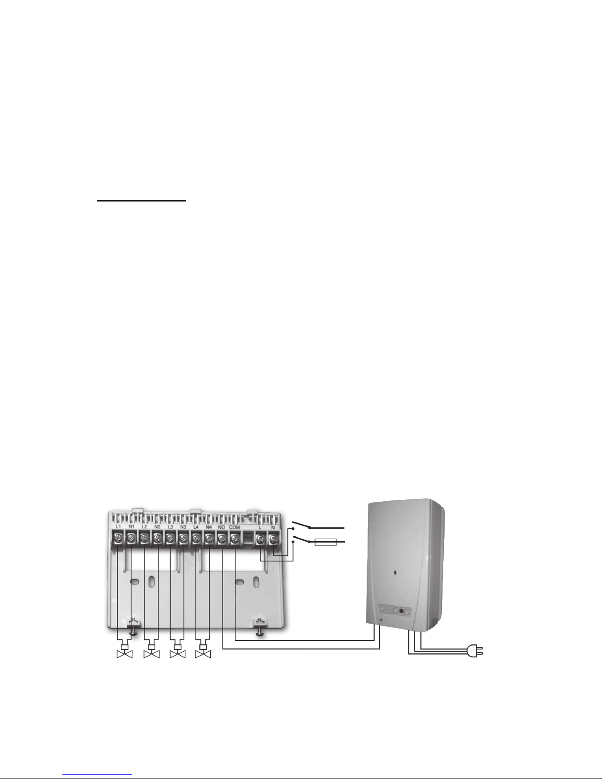
L1 N1 L2 N2 L3 N3 L4 N4 NO COM L N
230 V mains voltage should be supplied to the receiver unit. This provides
the power supply for the device, but this voltage does not appear on the
connection points of the relay that controls the boiler (NO and COM). We
propose to connect the neutral wire of the network to point N, while the
phase conductor to point L. We recommend using a fork type connection
including a switch for mains connection. Please de-energize the device
when heating is continuously not needed (e.g. summer).
- 9 -
Page 10
- 10 -
The receiver unit controls the boiler or air conditioner through a potentialfree relay whose connection points are: NO and COM. Connect the two
connection points of the heating or cooling equipment to be controlled to
terminals NO and COM, i.e. to the normally open terminals of the relay.
These connection points become closed following the heating/cooling
command of any thermostat.
If you would like to operate an old boiler or any other device that has no
connection points for thermostats, then the connection points NO and
COM of the thermostat should be connected to the mains cable of the
device, similarly as a switch would be connected.
ATTENTION! Always consider the loadability of the receiver unit and
follow the manufacturer’s instructions of the heating or cooling equipment. The device must be installed and connected by a qualified professional!
The voltage appearing at terminals NO and COM depends only on
the system being controlled, therefore the dimensions of the wire are
determined by the type of the device to be controlled. The length of the
wire is of no signicance, the receiver unit may be installed either near the
boiler or far away from it, but do not install it under the housing of the boiler.
If the distance between the transmitter and receiver units is too large due to
local circumstances and it makes the wireless (radio-frequency) connection
unreliable, install the receiver unit nearer to the place of thermostat.
Beside controlling the boiler, the receiver unit can also open/close the
valves of maximum 4 heating zones. Following the heating/cooling
command of one of the thermostat, 230 V AC, 50 Hz voltage appears on
the connection points of the zone valves associated with the thermostat.
The zone valves should be connected to the connection points L1 N1; L2
N2; L3 N3 and L4 N4 of the receiver.
- 10 -
230 V AC
50-60 Hz
230 V AC
50-60 Hz
N
L
Heating unit (boiler)
Zone valves
Rear panel of the receiver unit
(phase)
Page 11
- 11 -
Cut or break out the outlets to the required connection points at the
bottom of the receiver unit, in order to be able to connect wires to them.
ATTENTION! When the two units of the thermostat can only be located on
or outside the boundary of the range due to the layout of the building or the
shielding eect of the building structures between the units then, in order
to guarantee reliable RF connection, please install a
COMPUTHERM
Q2RF
type RF transmitter between the two units.
7.2 Putting the receiving unit into operation
Turn on the power supply to the receiver unit. A few seconds after the
LED lights ash once, the receiver unit becomes ready for operation. This
state is indicated by the blue LED light with the "A/M" sign. After this, you
can start tuning the receiver and the thermostats together. Following this,
you can start synchronization of the thermostats and the receiving unit
according to the following steps:
Receiving unit:
• Press and hold the button which belongs to the zone with which you wish
to synchronize thermostat
OMPUTHERM
Q5RF until the red LED beside
the button starts to ash.
Thermostat:
• Separate the back panel of thermostat
OMPUTHERM
Q5RF from the
front panel by pushing the latch located on the upper side of the case.
• Press and hold buttons „LEARN” and „RESET” located inside the ther-
mostat smultaneously.
• Release the „RESET” button and keep the „LEARN” button depressed
for additional 5 seconds.
• Following this, sign U1 appears on the display of the thermostat, indi-
cating that the thermostat can now be synchronized with zone 1 of the
receiving unit.
• With the help of and buttons select the zone from 1 to 4 with
which you wish to synchronize the thermostat.
• Press and hold the „LEARN” button located inside the thermostat for
approx. 3 seconds until on the receiving unit of
COMPUTHERM
Q5RF/
Q8RF the LED belonging to the zone concerned stops ashing.
- 11 -
Page 12

- 12 -
7.3 Resetting synchronization method of thermostat
COMPUTHERM
Q5RF
When you wish to reset operation of thermostat
COMPUTHERM
Q5RF
to default zone 1 then you can reset this option with the following steps:
• Press the „RESET” button located inside the thermostat and the
button on the front panel simultaneously.
• Release the „RESET” button but keep the button depressed for
additional 5 seconds.
• Now the synchronization method of the thermostat is reset to default
zone 1.
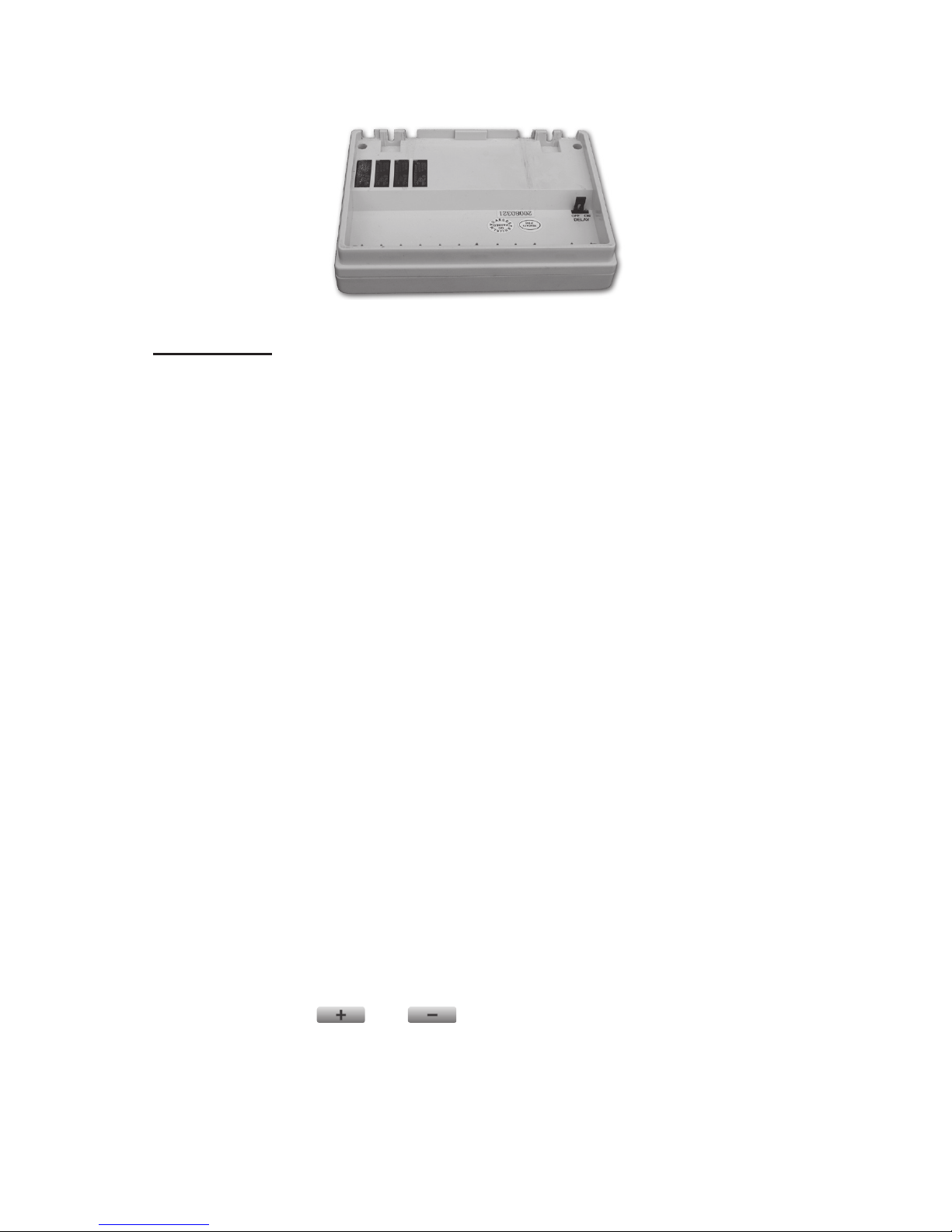
7.4 Activating the delayed start of the boiler function
When designing the heating zones, in order the protect the pump of the
boiler, it is reasonable to leave at least one heating circuit without a zone
valve (e.g. the bathroom circuit). In such a heating system, after the boiler is started, the heating water can freely circulate through the circuit(s)
without a zone valve until the zone valves are opened (the opening time
of an electro-thermal actuator is approximately 4 minutes). If the heating
system was not designed as described above, it is reasonable to activate
the delayed start of the boiler function in order the protect the pump of
the boiler. If this function is activated, then the boiler starts only 4 minutes after the receipt of the heating command, when the zone valves are
already opened. Under the factory default settings, this function is inactive. It can be activated at the back side of the receiver unit, by relocating
the jumper (black plug) with the “DELAY” sign. It is inactive in the “OFF”
position and active in the “ON” position of the jumper.
7.5 Transmission distance inspection
With the help of the and buttons you can check whether
the two units are within the transmission distance of the wireless (radio-frequency) connection. In order to do so, set the desired temperature
above room temperature by more than 0.2 °C, then reduce it below room
temperature by more than 0.2 °C. When detecting the ON and OFF control signals, the red LED light on the receiver unit switches on and off,
respectively. When the receiver unit fails to receive signals sent by the
thermostat, then the receiver unit is outside the transmission distance of
the wireless (radio-frequency) transmitter, thus they have to be placed
closer to each other.
ATTENTION! When the two units of the thermostat can only be located on
or outside the boundary of the range due to the layout of the building or the
shielding eect of the building structures between the units then, in order
to guarantee reliable RF connection, please install a
COMPUTHERM Q2RF
type RF transmitter between the two units.
- 12 -
Page 13
- 13 -- 13 -
7.6 Manual control of the receiver unit
Pressing the “A/M” button separates the thermostats from the receiver
unit. In this case, the boiler or air conditioner connected to the receiver
unit can only be turned on and off manually, without any temperature
inspection. The continuously illuminated blue LED indicates automatic (thermostat-controlled) mode, while its switched off state indicates
manual mode. In manual mode, pressing the 1, 2, 3, and/or 4 buttons of
the receiver unit turns on or off the boiler (or air conditioner) and opens/
closes the zone valves associated with the heating zones. The operation
of a heating zone is indicated by the illuminated red LED light associated with it. By pressing the “A/M” button again, the device quits manual
control and resumes automatic (thermostat-controlled) operation, which
is indicated by the illuminated blue LED light.
FREQUENTLY ASKED QUESTIONS
When you think that your appliance is operating incorrectly or encounter
any problem while the appliance is being used then we recommend that you
read Frequently Asked Questions (FAQ) available on our website, where we
collected the problems and questions that most frequently occur while our
appliances are being used, along with the solutions thereto:
http://www.quantrax.hu/gyik/
The vast majority of the problems encountered can be solved easily by
using the hints available on our website, without seeking professional help.
If you have not found a solution to you problem, please pay a visit to our
qualied service.
Warning! The manufacturer does not assume responsibility for any
direct or indirect damages and loss of income occurring while the
appliance is being used.
Page 14

Remark:
In addition to using modern temperature regulators, the following up-to-date
regulation methods also contribute signicantly to the improvement of the
comfort provided by the heating network, the energy eciency of the heating
network and the coecient of performance:
• By dividing the heating network into sections or zones (e.g. by
means of
COMPUTHERM
Q4Z zone controller and the associ-
ated
COMPUTHERM
zone valves) and with their separate regulation
we can ensure that every room (zone) is heated only when it is necessary.
(You can obtain information on the establishment of the heating network
and apparatuses and ttings needed for division into zones in our publication titled „Energy Savings and Comfort” which is also available on our
website www.quantrax.hu).
• Using programmable thermostats you can ensure that every room
(zone) is just heated according to a timetable preset in accordance with
the demands. (You can obtain information on the services provided by
COMPUTHERM
Q7; Q7RF and Q8RF programmable room thermostats
on our website).
• Using modern modular heating devices equipped with an external temper-
ature sensor the boiler can be operated at a higher eciency.
• Using low temperature heating networks (e.g. 60/40 °C) and condensing
boilers the temperature of the ue gas leaving the boiler can be reduced,
and this way fuel eciency can be improved signicantly.
PRODUCT INFORMATION DATA SHEET:
• Trademark:
• Model identier: Q5RF
• Temperature control class: I. class
• Contribution to the eciency of seasonal space heating: 1%
Page 15

TECHNICAL DATA
Technical data of the thermostats (transmitters):
‒ adjustable temperature range: 5 to 40 °C (in 0.5 °C increments)
‒ temperature measurement range: 3 to 45 °C (in 0.1 °C increments)
‒ temperature measurement accuracy: ±0.5 °C
‒ temperature calibration range: approx 3 °C
‒ selectable switching sensitivity: ±0.1 °C; ±0.2 °C
‒ storage temperature: -10 °C to +40 °C
‒ battery voltage: 2 x 1.5 V ALKALINE batteries
(LR6 type; AA size)
‒ power consumption: 1.5 mW
‒ battery lifetime: approx. 1 year
‒ operating frequency: 868.35 MHz
‒ dimensions: 100 x 80 x 22 mm (without holder)
‒ protection against environmental impacts: IP30
‒ weight: 80 g
‒ temperature sensor type: NTC 10 kΩ ±1% at 25 °C
Technical data of the receiver unit:
‒ power supply voltage: 230 V AC, 50 Hz
‒ power consumption: 0.15 W
‒ switchable voltage of the relay that
controls the boiler: 24 V AC/DC to 230 V AC, 50 Hz
‒ loadability of the relay that controls
the boiler: 6 A (0,5 A inductive load)
‒ voltage of the zone outputs: 230 V AC, 50 Hz
‒ loadability of the zone outputs: 1 A (0.5 A inductive load)
‒ transmission distance: approx. 50 m in open terrain
‒ protection against environmental impacts: IP30
‒ weight: 210 g
Total weight of the device: approx. 470 g
(2 thermostats+2 holders+1 receiver)
Page 16
The
COMPUTHERM
Q5RF type thermostat complies
with the requirements of standards RED 2014/53/EU
and RoHS 2011/65/EU.
Manufacturer: QUANTRAX Kft.
Fülemüle u. 34., Szeged, H-6726, Hungary
Phone: +36 62 424 133 • Fax: +36 62 424 672
E-mail: [email protected]
Web: www.quantrax.hu • www.computherm-hungary.hu
Origin: designed in the EU, made in China
Please watch our video presentation of the most important aspects of the usage of
this thermostat at our websites!
Copyright © 2018 Quantrax Ltd. All rights reserved.
 Loading...