

Page 1
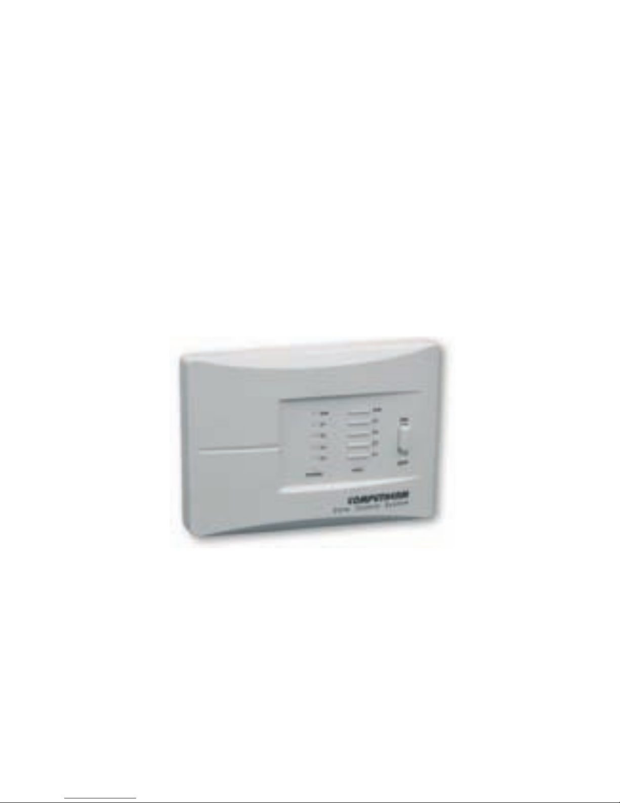
COMPUTHERM
Q4Z
zone controller
(for controlling 1 to 4 heating zones)
Operating Instructions
Page 2

1. General description of the zone controller
As the boilers usually have only one connection point for
thermostats, a zone controller is needed in order to divide the
heating system into zones, to control the zone valves and to
control the boiler from more than one thermostat. The zone
controller receives switching signals from the thermostats,
controls the boiler and gives commands to open/close the heating
zone valves ( max. 4 zones ) associated with the thermostats.
It can control 1 to 4 heating zones, which are regulated by a
wired switch-operated thermostat. The zones can operate
independently from each other or, in case of need, all zones can
operate at the same time.
2
Page 3

To control more than 4 zones at a time we recommend using
2 or more
COMPUTHERM
Q4Z zone controllers. In this case,
the potential-free connection points controlling the boiler (NO
and COM) should be connected to the boiler in parallel.
2. The connecTion poinTs of The zone conTroller,
mosT imporTanT Technical daTa
Each of the 4 heating zones have an associated pair of
connection points; one for a room thermostat and one for
a zone valve/pump. The thermostat of the rst zone (T1 )
controls the zone valve/pump of the rst zone (Z1), the
thermostat of the second zone (T2) controls the zone valve/
pump of the second zone (Z2) etc. Following the heating
3
Page 4

command of the thermostats, 230V AC voltage appears on
the connection points of the zone valves associated with the
thermostats, and the zone valves/pumps connected to these
connection points open/start. For ease of use, the connection
points associated with the same zone have the same color.
The rst and second zones, beside their regular connection
points, also have a joint connection point for a zone valve/
pump (Z1-2). If any of the rst two thermostats (T1 and/or T2)
switches on, then beside the 230V A C voltage appearing at Z1
and/or Z2, 230V AC voltage appears on Z1-2 too, and the zone
valv es/pumps connected to these connection points open/
start. This Z1-2 connection point is suitable to control the zone
valves/pumps in such rooms (e.g. the hall or the bathroom),
4
Page 5

which do not have a separate thermostat, do not need heating
at all times but need heating when any of the rst two zones heat.
The third and fourth zones, similarly to the rst and second
zones, have a joint connection point for a zone valve/pump
(Z3-4), too. If the third and/or fourth thermostat (T3 and/or T4)
switches on, then beside the 230V AC voltage appearing at
Z3 and/or Z4, 230V AC voltage appears on Z3- 4 too.
Moreover, the four heating zones also have a joint
connec t i on p oi nt fo r a zone valve/pump (Z1-4). If any of the
four therm o st ats (T1 , T2, T3 and/or T4) switches on, then
beside the 230V AC voltage appearing at Z1, Z2, Z3 an d /
or Z4, 230V AC voltage app ear s on Z1-4 too. This Z1-4
5
Page 6

connection point is suitable to control the heating in such
rooms (e.g. the hall or the bathroom), which do not have
a separate thermostat, do not need heating at all times
but need heating w hen any of the four zones heat. This
connec t i on point i s also suit abl e for controlling a central
circulating pump, w hic h starts whenever any of the heating
zones starts. When the delayed start of the boiler function is
activated (see the next paragraph), the delay is applicable for
the Z1-4 connection point too.
The rst, second, third and fourth zones also have a joint
potential-f r ee connect io n point that c o ntro ls the boiler (NO
and COM). These connection points clamp shut following
the heating command of any of the four thermostats, and
6
Page 7

this starts the boiler. This connection point is also equipped
with a delaying circuit. In case of using an electro-thermal
zone valve that operates slowly and all the zones are closed
when the boiler is inactive, then the boiler should be started
with a delay in order to protect the pump of the boiler. This
delay is activated in the ON position of the jumper (black plug)
“DELAY” (the delay is 4 minutes).
3. locaTion of The device
It is reasonable to locate the zone controller near the boiler
and/or the manifold in a way, so that it is protected from
dripping water, extreme heat and mechanical damage.
7
Page 8
8
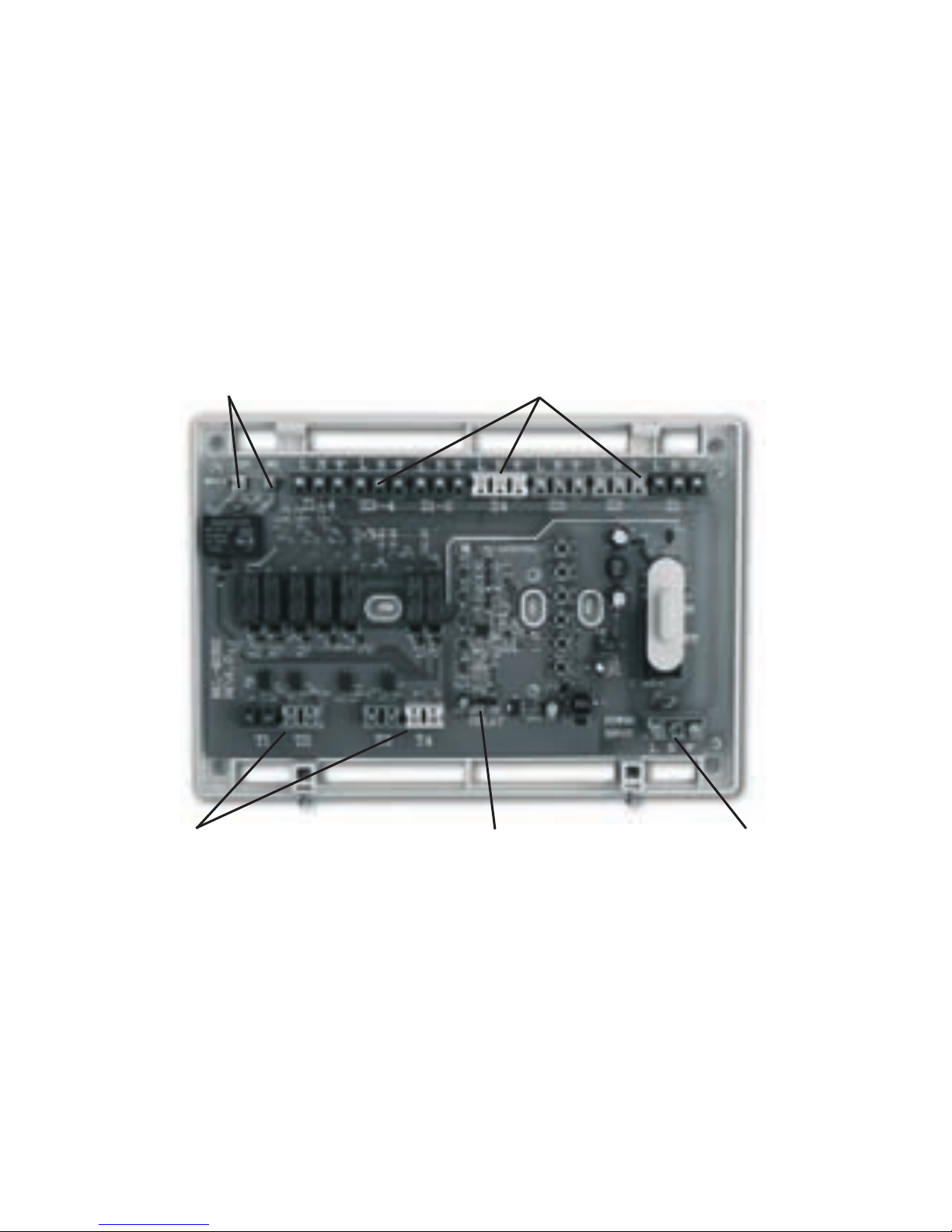
connection points controlling the boiler connection points of the heating zones
“DELAY” jumperconnection points of the thermostats connection points for power supply
Page 9

4. insTalling The zone conTroller and puTTing
iT inTo operaTion
To install the zone controller, detach its rear panel from its
front panel by loosening the screws at the bottom of the
cover. By this, the connection points of the thermostats, the
zone valves/pumps, the boiler and the power supply are
unblocked.
Select the location of the zone controller near the boiler and/or
the manifold and create the holes on the wall for installation.
Connect the wires of the needed heating equipment (the wires
of the thermostats, the zone valves/pumps and the boiler) and
the wires for power supply as shown in the gure below.
9
Page 10

Attention! The operating voltage of the thermostats, zone
valves and pumps connected to the zone controller is 230V
AC, the maximum loadability of the zones is 1A (0,5A inductive
load) per zone. This information should be considered at the
installation.
The s ize of t he co nne c ti o n points of the
COMPUTHE RM
Q4Z zone controller allow at most 2 or 3 devices to be
connected in parallel to any heating zone. If more than this
is needed for any of the heating zones (e.g. 4 zone valves),
then th e wires of the devices should be joined before they
are connected to the zone controller.
10
Page 11

After connecting all the wires to the zone controller, mount its
rear panel on the wall with the screws provided.
In case of using an electro-thermal zone valve that operates
slowly and all the zones are closed when the boiler is inactive,
then the boiler should be started with a delay in order to
protect the pump of the boiler. This delay is activated in the
ON position of the jumper (black plug) “DELAY”. (Under the
factory default settings this function is inactive.)
Replace the front cover of the device and secure it with the
screws at the bottom of the cover.
Connect the zone controller to the mains network.
11
Page 12

5. using The zone conTroller
Af ter inst alling t he d evice, put t ing it into operati on and
turning it on with its switch (position ON), it is ready for
operation, which is indicated by the illuminated state of
the red LED light with sign “POW ER ” and the blue LED
light with sign “A/M ” on the front panel. Then, following
the heating command of any of the thermostats, the zone
valves/pumps associated with the thermostat open/start
and the boiler also start s. (When t he de layed start of the
boiler function is activated, then the start of the boiler and
the 230V AC appea rin g at connectio n point Z1-4 is delayed
by 4 minutes.)
12
Page 13

Pressing t he “A/M” button separates the ther mostats
from the zone controller. In this case, the boiler and the
heating zones c an only b e started manually, without any
temperature insp ec tion. The c o ntinuously illuminated blue
LED i ndic ates automatic (thermost at- c ontr olled) mode,
while its switched of f state in dic ates manual m ode. This
function might be needed for example, if the battery has
run down in one of the thermostats. In manual mode,
pressing the 1, 2, 3, and/or 4 buttons of the zone controller
unit turns on or off the boiler and opens/closes the zone
valves associated with the heating zones. The operation of
a heating zone is indicated by the illuminated red LED light
associated with it. By pres sing the “A/M” button again or
13
Page 14

by pr essin g the “RESET” button, the d evice quit s manual
control and resumes automatic (thermost at- c ontr olled)
operation, which is indicated by the illuminated blue LED
light.
Page 15

Technical daTa
Any switch-operated room thermostat can be connected to the zone
controller, whose output relay has a loadability of 230V AC, min. 1A
(0.5A inductive load).
— Supply voltage: 230V AC, 50Hz
— Standby power consumption: 0.5W
— Voltage of the zone outputs: 230V AC, 50Hz
— Loadability of the zone outputs: 1A (0.5A inductive load)
— Loadability of the relay that controls the boiler: 24V AC/DC to 230V AC, 50Hz,
5A (2A inductive load)
— Delay period of the relay controlling the boiler: 4 minutes
Page 16
The
COMPUTHERM
Q4Z type zone controller complies with the
requirements of standards EU EMC89/336/EEC;
LVD 73/23/EEC and 93/68/EEC.
Importer:
Thermostats4U
Email: [email protected]
thermostats4U.co.uk
For better reading download this Operating
Instruction from our website!
For additional information visit:
 Loading...