

Page 1
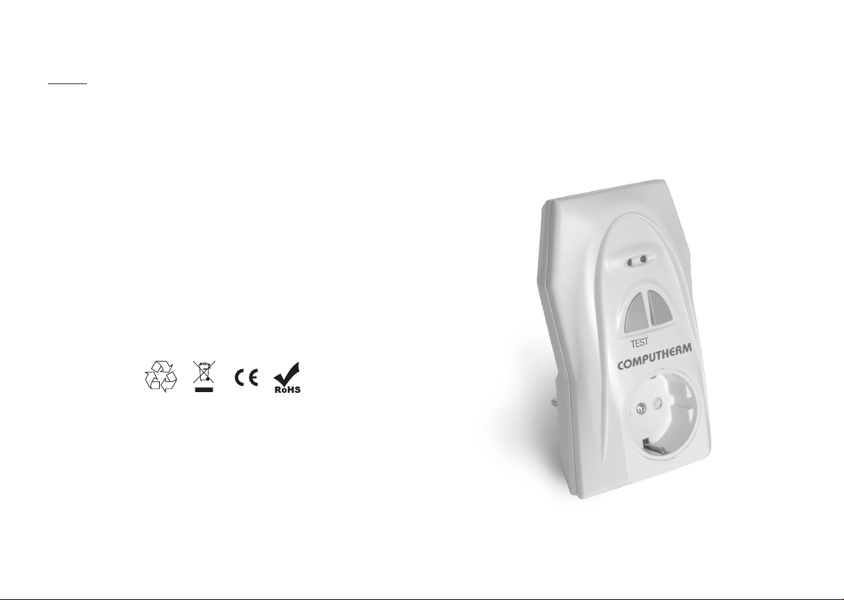
Make sure to plug the Q2RF wireless repeater approximately half way between
the Q3RF, Q5RF, Q7RF and Q8RF thermostat and Its receiver unit.
Warning! The manufacturer does not assume responsibility for any direct or in-
direct damages and loss of income occurring while the appliance is being used.
4. TECHNICAL DATA
• Power consumption: 0,5 W
• Power supply voltage: 230 V AC, 50 Hz
• Output voltage: 230 V AC; 50 Hz
• Maximum output current: 16 A (3 A inductive load)
• Operating frequency: 868,35 MHz
• Weight: 150 g
• Storage temperate: -10 ºC – +40 ºC
• Protection against environmental impacts: IP30
The
COMPUTHERM
Q2RF signal repeater plug complies
with the requirements of the standards
RED 2014/53/EU and ROHS 2011/65/EU.
Manufacturer: QUANTRAX Kft.
Fülemüle u. 34., Szeged, H-6726, Hungary
Phone: +36 62 424 133 • Fax: +36 62 424 672
Web: www.quantrax.hu • www.computherm-hungary.hu
Email: [email protected]
Country of origin: China
COMPUTHERM
Q2RF
wireless (radio-frequency) signal repeater (range
expander) plug for enlarging the range of the
COMPUTHERM
Q3RF, Q5RF, Q7RF, Q8RF
thermostats
Copyright © 2018 Quantrax Ltd. All rights reserved.
Operating Instructions
Page 2

1. GENERAL DESCRIPTION
The
COMPUTHERM
Q3RF, Q5RF, Q7RF and Q8RF thermostats to increase their wireless range.
The original range of Q3RF, Q5RF, Q7RF and Q8RF thermostats is 50 m in
open area, which can be significantly shortened by the structure of the building.
To be able to use the Q3RF, Q5RF, Q7RF and Q8RF thermostats in larger
buildings too, it is advised to use a wireless signal repeater. This can be achieved by
using the
COMPUTHERM
wireless thermostats and retransmits the signal to the receiver unit, thus making the
range larger. The Q2RF plug should be connected to the mains voltage (230 V, 50
Hz), meanwhile on the output of the Q2RF plug the 230 V, 50 Hz mains voltage also
appears. The maximum load of the plug is be 16 A (3 A inductive).
Q2RF plug was developed for the
Q2RF wireless repeater: it receives the signals of the
COMPUTHERM
2. PUTTING THE WIRELESS REPEATER INTO OPERATION
Warning! Modifying the socket can cause electric shock or product failure.
When choosing the location of the signal repeater unit you should remember that
bulky metal objects (e.g. a boiler, buffer tank, etc.) and metal building structures
may have an adverse effect on propagation of radio waves. If it is possible, in order
to ensure trouble-free RF connection, we recommend that you install the receiving
unit at a height of 1.5 to 2 m and at a distance of 1 to 2 m from the boiler or other
bulky metal constructions. We recommend that you check reliability of RF connection at the place selected before installing the receiving unit.
Connect the
approximately half way between the Q3RF, Q5RF, Q7RF and Q8RF thermostat
and Its receiver unit. After a couple of seconds the LEDs on the front panel of the
plug flash once, after which the plug is ready for operation. Without tuning the device together with the thermostat or its receiver unit, it receives the signals from all
Q3RF, Q5RF, Q7RF and Q8RF thermostats in its range (the red LED flashes 3
times), after which it transmits the signal to the receiver unit (the green LED flashes
3 times) using the same security code. It causes absolutely no problems if there
are more thermostats working in the range of the wireless repeater: as the security
codes are kept for the repeated signals, an incorrect switch is not possible.
COMPUTHERM
Q2RF wireless repeater plug to the mains voltage,
3. FAST CHECK OF THE OPERATION OF THE WIRELESS
REPEATER
It is easy to check the range of the Q3RF, Q5RF, Q7RF and Q8RF thermostats
in a given environment by increasing the distance between the thermostat and the
receiver unit. It is also simple to check the range expanding ability of the Q2RF plug
by connecting it to the mains voltage between the thermostat and the receiver unit
when they are far away from each other.
Further, by pressing the „TEST” button, the verification of the operation of the Q2RF
plug is easy, fast and can be done within one room by following the steps below:
a. Unplug the Q2RF device, in case it was plugged in before, and wait approx-
imately 1 minute to make sure that the capacitors inside the device are discharged.
b. Press and hold down the grey „TEST” button on the front side of the device, and
meanwhile connect it to the mains voltage. Do not release the „TEST” button until
the LEDs on the front side of the device first start flashing alternately, then after
a couple of seconds they become continuously illuminated for approximately 2
seconds together. After the LEDs switch off (become unilluminated), the device
is in „TEST” mode, and it is ready for the verification of its operation.
c. The „TEST” mode of the wireless repeater inverts the signal sent from the ther-
mostat to the receiver unit. When the thermostat sends a switch on command to
the receiver unit and the sign of the heating/cooling equipment working appears
on the display of the thermostat, the receiver unit turns on. A few seconds later
the wireless repeater sends a switch off command to the receiver unit, so the receiver unit switches off. Similarly, a couple of seconds after the switch off signal
of the thermostat, the wireless repeater sends a switch on signal to the receiver
unit.
The inverted operation shows that the signal repeater plug is working properly.
With the help of this „TEST” mode, it is easy and fast to check the proper operation of the Q2RF wireless repeater even if it is close to the thermostat and the
receiver unit.
d. To finish using the „TEST” mode, unplug the device from the mains voltage and
wait approximately 1 minute to make sure that the capacitors are discharged. After this connect the device to the mains voltage again, and then it is ready to use.
 Loading...