

Page 1
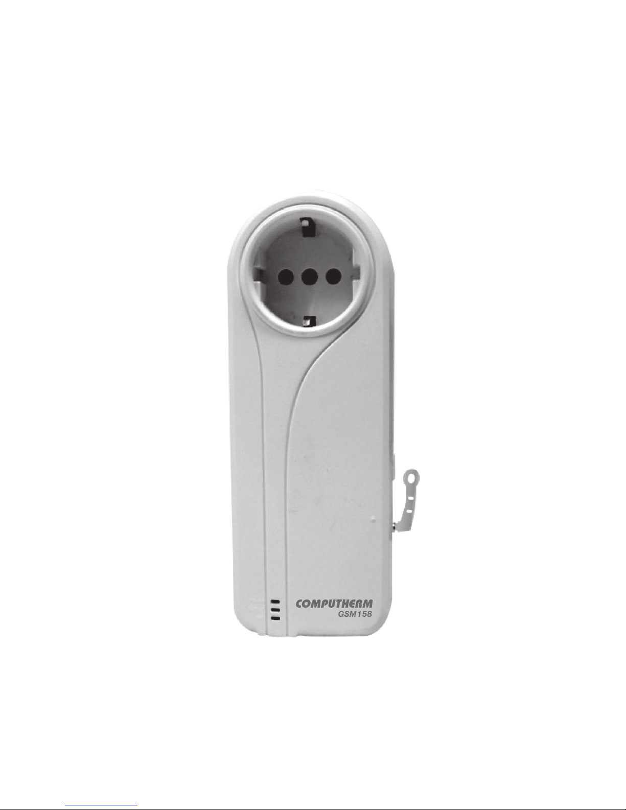
COMPUTHERM
GSM158
Power socket
User manual
Page 2

Page 3

Thank You for purchasing the
COMPUTHER M
GSM158.
The
COMPUTHER M
GSM158 power socket is a remote
controlled socket using a Pay as you Go contract SIM.
The power supply output of the socket can be turned
on or off remotely by the SMS (Short Message System)
command or local controlled by its function buttons. It is
an intelligent power supply socket that can be controlled
anytime and anywhere by users’ mobile phone.
COMPUTHER M
GSM15 8 is designed for any electrical ap-
pliance for business or family use up to 16amp output with
a power consumption of up to 3KW.
When used with the removable temperature sensor
COMPUTHER M
GSM158 can switch power on or off
according to the environment temperature. It is suitable
for power control of heating or refrigeration equipment by
keeping the environmental temperature within a preset
range or xed temperature value.
All services and functions need to be supported by the
GSM network and a SIM card.
The instruction manual provides both a quick start set up
and then a more advanced operation when the user wishes to programme the socket via temperature or time/date.
- 1 -
Page 4

CONTENTS
Safety recommendations ........................................................ 04
Disclaimer Notice .................................................................... 05
Chapter 1 Features and Accessories
1.1 Main functionality .............................................................. 07
1.2 List of contents .................................................................. 07
1.3 Sockets instructions .......................................................... 07
1.4 Temperature sensor instruction ......................................... 08
1.5 Light indicators .................................................................. 08
Chapter 2 Quick Start
2.1 Install the SIM card and temperature sensor .................... 08
2.2 GSM Power on/off .............................................……….…. 08
2.3 Add a Master number to the socket ................................... 09
2.4 Socket output switching on/off .......................................… 10
2.5 Loss of External power supply notication ...........………… 10
Chapter 3 Advanced Settings
3.1 Denition of different users ........................................…… 12
3.1.1 User authorization level .....................................……….. 12
3.1.2 About the SIMS Command .................................………. 12
3.1.3 Add a master number to the socket ......................…….. 13
3.1.4 Change the master number ........................................... 13
3.1.5 Add additional user numbers .......................................... 14
3.1.6 Check additional user numbers ..................................… 14
3.1.7 Delete additional number ............................……………. 14
3.2 Switching on/off the socket output manually ..............…… 15
3.2.1 Switching on/off by SMS ...................................……...… 15
3.2.2 Switching on/off by M button ........................…………… 15
3.2.3 Switching on/off by calling ......................……………..… 16
3.3 Delayed switch on/off the socket output ........................… 16
3.4 Controlling socket via pre set days/times………………..… 17
3.4.1 Set timed switching of power on/off .......................……. 17
3.4.2 Set time period of power on/off .........................…...…… 17
3.4.3 Disable timing switching on the output ..........………..… 18
3.5 Auto-control the socket output by temperature ..........…… 18
3.5.1 Enable auto-controlled by temperature ...…………......... 18
3.5.2 Set temperature range to switch on/off the output…….… 19
3.5.3 Disable auto-controlled by temperature…………….....… 20
3.6 SIMS notication upon the socket output changing .......... 20
3.7 Check status ................................…………………………. 20
3.8 Resetting the socket ....................................……………… 22
Chapter 4 Maintenance .................................………..……… 23
Chapter 5 Troubleshooting ......................................……..… 25
Chapter 6 Main Technical Parameters ...................………… 26
Chapter 7 SMS commands list ...........................…………… 26
- 2 -
Page 5

INFORMATION
1. Purchase a GSM SIM card (mobile phone card)
from GSM network provider and insert it in the
socket. This SIM card number is referred as
COMPUTHER M
GSM158 number on this brochure.
2. The user needs to activate the PAYG SIM with
credit and disable the pin code function then the
COMPUTHERM
GSM15 8 is ready to programme.
We recommend before choosing your network
provider you check their signal strength where the
socket is to be located.
3. Be sure to keep the Password and mobile number
safe and we recommend you change the preset
password of 1234. Do not disclose this information
to anyone other than the authorized users in order to
ensure no misuse.
NB: Although we recommend PAYG SIMS for easy access
and set up of the
COMPUTHER M
GSM15 8, contract
SIMS can also be used but as we are only sending SMS
messages as PAYG SIM is very cost effective.
SAFETY RECOMMENDATIONS
1. This socket was designed for business or family use for
any appliance not exceeding 16amps or 3KW output.
2. Before using this socket, check if mobile phones can
be used in the area.
3. This socket was designed for indoor use. Do not use
it in wet, chemically aggressive or dusty environment.
4. Don’t make two plugs of socket short circuit.
5. Don’t touch the socket jack by any metal objects or hand.
6. Do not open the case. If faulty return to manufacturer.
7. This socket is a wireless signal transmission socket. Keep
it away from electronic equipment likely to interfere with
the wireless signals, in order to avoid signals interference.
8. Keep the socket and its accessories out of the chil-
dren reach.
9. This socket doesn’t guarantee safe power source discon-
nection, only functional switching of power is performed.
10.Should the
COMPUTHER M
G SM158 not function as
- 3 -
Page 6

detailed in this instruction book, please contact your
supplier for technical support or a replacement product under warranty.
DISCLAIMER NOTICE
1. We operate on a policy of continuous development
and therefore we reserve the right to make changes
and improvements to any of the sockets described in
this document without prior notice.
2. For the latest socket information, please check with
your supplier.
3. We cannot be held responsible in any way should this
product be used other than for the intended purpose.
4. We hold no responsibility for any loss of income or any
special, incidental, consequential or indirect damages
howsoever caused.
5. The contents of this document are provided “as is”.
Except as required by applicable law, no warranties
of any kind, either expressed or implied, including, but
not limited to the accuracy, reliability or contents of
this document. We reserve the right to revise this document or withdraw it at any time without prior notice.
- 4 -
Page 7

CHAPTER 1
FEATURES AND ACCESSORIES
1.1 Main Functions
• This socket uses a PAYG or contract GSM SIM card.
• Remotely operate of any electric appliance connected
to switched socket by SMS command.
• Remotely operate of any electric appliance connected
to the micro relay output jack by SMS command.(For
COMPUTHER M
GSM158+ only)
• Input: 110~250V/50Hz
• Output Max: 16A.
• Relay: 30A/240V relay with two working status power
on/off for output outlet.
• M button: To manual control output power on/off.
• Time delayed control of output power on/off.
• Auto operation by preset schedule.
• Supplied with plug in external temperature sensor.
• Automatic operation by preset upper/lower temperature thresholds.
• Receive environmental temperature reading via simple SMS command
• Supports 1 Master and 4 additional numbers/users
• Automatic time/date synchronisation.
• SMS notication on change external power supply.
1.2 List of Contents
• 1 X
COMPUTHER M
GSM158 controlled power socket
• 1 X External temperature sensor
• 1 X User manual
- 5 -
Page 8
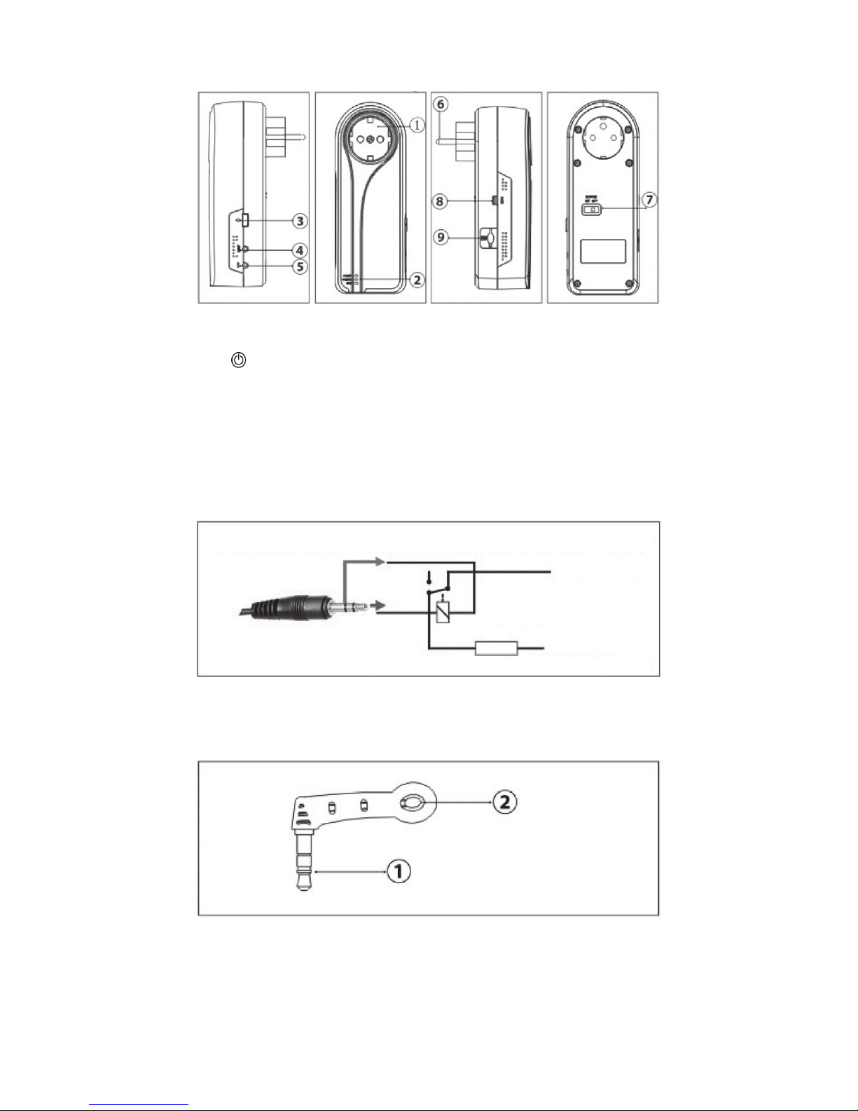
1.3
COMPUTHERM
GSM15 8 Schematic Drawings
1 – Electrical Outlet
2 – Indicator light (Power, output, GSM);
3 – „ ” On/Off button
4 – Temperature sensor port
5 – Output jack
6 – Socket plug
7 – Power switch
8 – Data port
9 – SIM card holder
Output jack
1.4 Temperature Sensor Instruction
1 – Standard 3.5mm interface
2 – Temperature sensor
Figure3
Figure1
Microrelay designed for switching of external electrical contacts
It can switch 12VDC/0.5A max.
~AC230V
Figure2
- 6 -
Page 9

CHAPTER 2
QUICK START
2.1 Install the SIM card and temperature sensor
• Turn the power switch to “OFF” position.
• Insert SIM card into SIM bay and push it gently inside
until you hear/feel a click, so it becomes locked inside
bay.(To remove SIM from the socket, gently push the
SIM inside the bay until you hear/feel a click again, card
will become unlocked and now pull it out of the bay.)
• Insert the temperature sensor into the temperature
port until it is seized.
2.2 GSM Power on/off
Power on:
1. Turn the power switch to “On” position (see 7 on
Figure 1)
2. Plug the G S M15 8 into AC power socket.
The “Green” power light will illuminate and the
“Blue” GSM light will ash for about 20 seconds
before staying on constantly to conrm GSM signal available. A long “beep” tone can be heard (if
“beep” warning tone is enabled).
3. Insert your electronic appliance into the G S M158
electrical outlet (see 4 on gure 1).
INDICATOR ACTION
Turning o
Turning o
Constant light
No power supply input
Not installed SIM card, invalid SIM card or
the power switch of socket is "OFF"
Has power supply input
STATUS
Power light (Green)
Flash
Turning o
Several times
Long Beep
Constant light
Constant light
Be busy or searching GSM network
The socket outlet cuts power supply
Alarm warning
The socket is successfully reset to its settings
Successfully connected to the GSM network
The socket outlet has power supply
"Beep" warning tone
(Default turning on)
Output light (Red)
GSM light (Blue)
- 7 -
Page 10

4. “ ” button (see 4 on gure 1) can be pressed for
about 1 second to manually switch ON or OFF the
socket power output. The socket is now ready to be
programmed for remote use.
Power off:
1. Turn the power switch to “off” position. The blue
light turns off.
2. The socket outlet can work as normal power socket. SMS command & “ ” button is disabled.
Note: The unit can be turned off by the switch (See 7
Figure 1) when not required for a period of time or by
pressing the “ ” button for 1 second (See 3 Figure
1). The GSM network signal in the socket location can
affect the unit’s functionality and therefore we recommend that the signal strength is tested before lugging
external devices into the socket to be controlled. This
can easily be done by sending an SMS to the socket
rst time to see the response time which will indicate
signal strength in addition to a continuous blue light.
2.3 Add a Master number to the socket
The user must edit and send the following SMS to socket
via his/her mobile phone which will become the Master
number in order to:
Add a Master number to the socket:
#99#SIMCardIDnumber#NewCode#
(i.e. #99#83746125#7ab2#)
Note: new code can be 1~6 letters, or digitals or com-
bination of them.
Successful SMS reply
Welcome. Registration is successful.
New Password is: 7ab2.
Time is: 2012/12/14 15:27
2.4 Socket output switching on/off
Method:
Method 1: To press “ ” button for 1 second (See 3 Figure 1)
Method 2: The Master user sends following SMS mes-
sage to socket in order to:
- 8 -
Page 11

Switch ON the socket output: #01#
Switch OFF the socket output: #00#
Successful SMS reply
Status ON/OFF
Temp: 18C
Temp control: function ON/OFF
Schedule control: function ON/OFF
Delay control: function ON/OFF
2.5 External power supply notication
Lost external power supply:
If the plug of the GSM158 is disconnected from external
AC power or lost of the AC power occurs, all functions of
the socket are deactivated including the M button and will
notify the user “Main Electricity Supply Lost” together
with temperature reading.
The unit will notify the user “Main electricity supply lost
Temp:18C”.
Resume external power supply:
If the AC power of the GSM15 8 is available again, the
SMS notication will be sent to the user “Main Electricity
Supply Restored, Status: ON/OFF Temp:18C”.
When the external power supply is resumed, the output
of GSM158 will keep the same status as that of before
the external power supply failure if the power switch of
the G SM158 is not turned off. For example, if the output
is switched on before the external power supply cut off,
the output will be switched on when the external power
supply is resumed. If the power supply is switched on and
off frequently, GS M15 8 will send reminding SMS.
CHAPTER 3
ADVANCED SETTINGS
3.1 Dene the users
3.1.1 User authorization level
All the settings of GSM158 can be set or adjusted via a
SMS command.
There are two mobile phone user controlling levels.
- 9 -
Page 12

Master User:
Only on Master user has authorization to use all features
of GSM158.
In order to enable all the functions on the socket, the Master user must store his/her mobile number in the socket’s
memory. Only one Master’s mobile number (Master number) is allowed for a socket.
Family User:
There are four Additional users have authorization to use all the
functions of GSM158 except dening the users including add/
delete users, change password, and SMS alerts, notication.
3.1.2 About the SMS Command
• The password must be 6 letters, or digitals, or combination of them.
• The original password is 1234.
• The limit of digits that are allowed for the phone num-
ber is three to sixteen.
• G S M158 will reply to the user after it receives the
SMS command.
Note:
- The # symbol must NOT be ignored when typing an
SMS command.
- No allow any space within the commands.
3.1.3 Add a master number to the socket
Description:
If GSM158 is being used for the rst time, or GS M15 8 has
been reset to factory settings, the Master user’s number
must be programmed into the socket.
Method:
The user must edit and send the following SMS to socket
via his/her mobile phone (the phone number will be the
Master number) in order to:
Add a master number to the socket:
#99#SIMCardIDnumber#Code#
Successful SMS reply
Welcome. Registration is successful.
New Password is: 1234
Time is: 2012/12/14 15:27
- 10 -
Page 13

Failed SMS reply
If a user tries to add another Master user again,
GSM158 will send a notication via SMS stating “The
master user already exists”. You should change the
Master number (Refer to Chapter 3.1.4).
3.1.4 Change the master number
Method:
Method 1: The Master user sends following SMS message
in order to:
Change the master user’s number:
#14#Newphone#oldphone#code#
Method 2: The user reset GS M15 8 to factory settings to
remove old Master number before setting the new one
(Refer to Chapter 3.8).
Successful SMS reply
New master number set successfully.
Master number: 13456007800.
Password: 56egy8.
Successful SMS reply will be sent to the new Master
user. Then the old Master user’s number will not be
able to control GSM158 anymore.
3.1.5 Add family number
Up to 4 Additional user’s number can be stored on one socket.
Additional users have the authority to use all the functions
except adding/deleting users, change password.
Method:
The Master user sends following SMS message in order to:
Add a family number:
#06#FamilyNumber#code#
(i.e.: #06#13566537908#56egy8)
Successful SMS reply
Family number xxxxxxxxx set successfully.
Add several family numbers:
#06#Family Number1# ...# Family Number4#code#
Additional Number should be the Additional user’s
mobile phone number.
- 11 -
Page 14

Successful SMS reply
Family number xxxxxxxxx, xxxxxxxxx, xxxxxxxxx set successfully.
3.1.6 Check Additional user’s number
Refer to Chapter 3.7 Check status.
3.1.7 Delete Family number
Method:
The Master user sends following SMS message in order to:
Delete a family number:
#113#family number#code# (6)
Delete several family numbers simultaneously:
#113#family number1# ...# family number 4#code# (7)
Delete all Additional numbers:
#113#code# (8)
Successful SMS reply
Family number xxxxxxx has been deleted.
Failed SMS reply
Phone xxxxxx does not exist.
3.2 Switching on/off the socket output manually
Description:
When the socket output is switching on, GSM15 8 offers
power supply for electronic appliance which being connected with it; the red indicator light is constant turning on.
Otherwise L158has no power supply for electronic appliance and the red light is turning off.
Note:
If the socket output status is changed manually (including
pressing the M button, sending SMS or making phone call),
the preset timing, delaying or temperature control f the
socket will be invalid automatically with a SMS notication,
but the setting time range and temperature range parameters will be saved until GSM158 is reset to factory settings.
- 12 -
Page 15

3.2.1 Switching on/off by SMS
Method:
The user sends following SMS message in order to:
Switch on the socket output manually:
#01#
Cut off the socket output manually:
#00#
Successful SMS reply
Status ON/OFF
Temp: 27C
Temp control: function ON/OFF
Schedule control: function ON/OFF
Delay control: function ON/OFF
3.2.2 Switching on/off by “ ” Button
Keep press “ ” button on the G S M158 for one second.
The red light will indicate the output changes and the SMS
reply is same with Chapter 3.2.1.
3.2.3 Switching on/off by calling
Description:
If the Master user calls GSM15 8, the socket output will be
switched on or cut off automatically when the user hears the
ring tone in the phone. The calling will be hung up automatically
if the user doesn’t hang up the call.
This function is default activated.
Method:
The user sends following SMS message in order to:
Enable switching on/off the output by calling (Default):
#18#1#
Disable switching on/off the output by calling:
#18#0#
Successful SMS reply
Control the socket power output status by calling activated/
deactivated.
- 13 -
Page 16

3.2.4 Switching on/off auxiliary output
Description:
The 3.5mm port for auxiliary output can connect to any device
up to 12VDC, 0.5A max.
Note:
Please respect maximum rating of the auxiliary microrelay output-12VDC, 0.5A. Don’t overload the socket, as this
may damage or shorten life span of the internal switching
relays, which is not covered by warranty. It’s recommended
to use external power relays/contactors in case of higher
current is required and/or capacitive/inductive load with
high startup current needs to switched.
Method:
The user sends following SMS message in order to:
Switch on the auxiliary output:
#11#1#
Switch off the auxiliary output:
#11#0#
Successful SMS reply
Auxiliary output: ON/OFF.
3.3 Delayed-switch on/off the socket output
Description:
The output of GSM158 can be set to delay switch on or
cut off for a period with SMS commands.
The “delayed switch on/off the socket” function will be invalid when the GSM indicator light is not constant lights;
that means, if the external power of GSM15 8 is cut off or
SIM card cannot work normally, “delayed switch on/ off
the socket” function is invalid, so for unstable power-supply area, it is not suggested to use this function.
Method:
The user sends following SMS message in order to:
Delay switching on the output after a certain minutes:
#138#1 Minutes#
Delay switching off the output after a certain minutes:
#138#0#Minutes# (16)
Minutes are time parameters, its range is 1-720.
- 14 -
Page 17

Successful SMS reply
Status: ON/OFF
Delay control: function ON
The switch will open/close after ** minutes!
When the time expire, the socket will send you SMS
“Time is expired, the switch is open/close.”
3.4 Timed switching on the socket output
3.4.1 Enable timing switching on the output
Description:
The output of GSM15 8 can be set to switch on for a period like
every Monday, or every day or every Monday to Friday, etc.
Method:
The user sends following SMS message in order to:
Enable timing switch on/off the output:
#128#01# (17)
Successful SMS reply
Temp control: function ON/OFF
Delay control: function ON/OFF
Schedule control: function ON
Workday, Startime-Endtime
3.4.2 Set time period to switch on and off the output
Description:
After successful setting of time period to switch on the
socket output, the schedule parameter will be saved on
the socket until GSM15 8 is reset to factory settings, no
matter if the external power supply is cut off or the power
switch is turned off. But the “timed switch on the output”
feature is applied only when command 17 be set.
Method:
The user sends following SMS message in order to:
Set time period to switch on and off the output:
#128#WorkDay#StartTime#EndTime#
Set time to switch on the output:
#128#WorkDay#StartTime#0#
Set time to cut off the output:
#128#WorkDay#0#EndTime#
- 15 -
Page 18

WorkDay: one digit, the values lie in the range of “0”
to “8”. The following table contains the descriptions of
each value.
0 - Monday to Friday
1 - Monday
2 - Tuesday
3 - Wednesday
4 - Thursday
5 - Friday
6 - Saturday
7 - Sunday
8 - Everyday
StartTime and EndTime: consists of 4 digits (hh:mm)
and works on a 24 hour clock. If the EndTime is later
than StartTime, the period is in the same day. If the
EndTime is earlier than StartTime, the EndTime is on
next day.
The socket output will switch on at the StartTime and
cut off at the EndTime.
For example:
#128#0#0000#2130#
This means the socket will open on 00:00 and close on
21:30 every Monday to Friday.
#128#0#2130#0000#
This means the socket will open on 21:30 and close on next
day 00:00 every Monday to Friday.
#128#1#0900#0#
This means the socket will open on 09:00 every Monday.
#128#5#0#1800#
This means the socket will close on 18:00 every Friday.
Successful SMS reply
Temp control: function ON/OFF
Delay control: function ON/OFF
Schedule control: function ON
Monday to Friday, 00:00-21:30
3.4.3 Disable timing switching on the output
Method:
The user sends following SMS message in order to:
Disable timing switch on/off the output:
#128#00#
- 16 -
Page 19

Successful SMS reply
Temp control: function ON/OFF
Delay control: function ON/OFF
Schedule control: function OFF
Workday, Startime-Endtime
3.5 Auto-control the socket output by temperature
3.5.1 Enable auto-controlled by temperature
Description:
The external temperature sensor must be inserted into the
TEMP port of GS M158. The output status of the socket
can be controlled by the environmental temperature
automatically.
For example: G SM158 is used for the power control of
the heating apparatus. Please check the other function
status(delay control and schedule control) to make sure
they are OFF in case the outlet output changes during the
temperature controlling time.
Method:
The user sends following SMS message in order to:
Enable auto-control the output by temperature:
#159#01#
Successful SMS reply
Status ON/OFF
Delay control: function ON/OFF
Schedule control: function ON/FF
Temp control: ON
Temp: 25C
Mode: Heating/Cooling
Range: LowTemp-HighTemp
The GS M15 8 will switching on or cut off the output
automatically according to the temperature range
setting.
3.5.2 Set temperature range to switch on/off the output
Description:
After successful setting of temperature range, the
temperature parameter will be saved on the socket until
GSM15 8 is reset to factory settings, no matter if the
external power supply is cut off or the power switch is
- 17 -
Page 20

- 18 -
turned off. But the “Auto-controlled by temperature” feature
is applied only when command 20 is set.
Method:
The user sends following SMS message in order to:
Set temperature to switch on/off the output:
#159#Mode#LowTemp#HighTemp#
Mode is the control selection:
For coldness, mode=0. For warmness, mode=1.
Temp means temperature value, the range is –10C
to 49C.
Temperature unit is degree Celsius.
Example 1: set commands: #159#0#20#30# when the
environmental temperature is 35 degrees (above the
limitation of 30 degrees in the command) the socket output will be on, cooling apparatus starts working; when
the environmental temperature is 18 degrees (below the
limitation of 20 degrees in the command), the socket output will be off, heating apparatus stops working.
Example 2: set commands: #159#1#10#20# when
the environmental temperature is 5 degrees (below
the limitation of 10 degrees in the command), the
socket output will be on, heating apparatus starts
working; when the environmental temperature is 24
degrees (above the limitation of 20 degrees in the
command), the socket output will be off, cooling apparatus stops working.
3.5.3 Disable auto-controlled by temperature
Method:
The user sends following SMS message in order to:
Disable auto-control the output by temperature:
#159#00# (22)
Successful SMS reply
Status ON/OFF
Delay control: function ON/OFF
Schedule control: function ON/FF
Temp control: OFF
Temp: 25C
Mode: Heating/Cooling
Range: Low Temp-HighTemp
Page 21

- 19 -
3.6 Auto-control the socket output by temperature
3.6.1 Over-temperature alarm
Description:
The socket will auto-send the SMS alarm message to
master user and “Beep” if the surrounding temperature is
detected out in the pre-set temperature range or out of the
pre-set temperature range.
Method:
The user sends following SMS message in order to:
Enable over-temperature alarm:
#170#01#
Set in range alarm temperature limit:
#170#1#LowTemp#HighTemp#
Set out of range alarm temperature limit:
#170#0#LowTemp#HighTemp#
Disable over-temperature alarm:
#170#01#
Successful SMS reply
Temperature alert: function ON
Temp: 25C
Mode: In range/Out of range
Min Temp:10C
Max Temp:20C
Mode is the control selection:
For alarm in pre-set temperature range, mode=1. For
alarm out of pre-set temperature range, mode=0.
Temp means temperature value, the range is –10C
to 49C.
Temperature unit is degree Celsius.
Example 1: set commands: #170#1#20#30# when the
environmental temperature is 21 degrees (in the range of
20-30C in the command) the socket will send SMS alerts
to master user and “beep” until you disable the function.
Example 2: set commands: #170#0#20#30# when
the environmental temperature is 11 degrees (out of
range of 20-30 in the command) the socket will send
SMS alerts to master user and “beep” until you disable the function.
Page 22

3.6.2 Temperature rapid changing alarm
Description:
A time period value and temperature changing value can
be preset. If the surrounding temperature changes to the
preset value within the preset time period, a SMS alert
message will be auto-sent to master user’s mobile phone.
This feature depends on the temperature sensor and
settings.
Method:
The user sends following SMS message in order to:
Enable rapid changing temperature alarm:
#160#1#
Set time period and temperature changing value:
#160#Temp#Time#
Disable rapid changing temperature alarm:
#160#0#
Temp: The values lies in the range from 1-60
centigrade degree.
Time: The values lies in the range from 1-30 minutes.
Please set up the temp and time value when you use
the function at rst time.
The sensor will detect the temperature every 6
second. Once the temperature changes rapidly, the
socket will auto send the SMS alerts to master user
every minute and it “beep” until you disable it.
Successful SMS reply
Temperature rapid changing: function ON
Delta: 4C
Time: 2minutes
3.7 SMS notication upon the socket output changing
Description:
GSM15 8 will default notify the user when the socket output
changing. A SMS notication will be sent. The Master user
can enable/disable this SMS notication.
- 20 -
Page 23

Method:
The user sends following SMS message in order to:
SMS notification upon the socket output changing (Default):
#130#1#
No SMS notification upon the socket output changing:
#130#0# (24)
Successful SMS reply
SMS notification upon the socket output changing manually.
NO SMS notification upon the socket output changing
manually.
3.8 SMS notication upon power supply changing
Description:
GSM15 8 will default notify the user when the power
supply changing.
For example:
Main electricity supply lost!
Temp: 24C
or
Main electricity supply restore!
Status: ON/OFF
Temp:24C
The Master user can enable/disable the function of notifying
user when the power supply changes by sending SMS:
Enable the function of notifying:
#12#1#
Disable the function of notifying:
#12#0#
Successful SMS reply
SMS notification upon the socket output changing manually.
NO SMS notification upon the socket output changing
manually.
3.9 “Beep” warning tone
Method:
The master user sends following SMS command in order to:
Enable the “Beep” warning tone (Default):
#19#1#
- 21 -
Page 24

Disable the “Beep” warning tone:
#19#0#
Successful SMS reply
Beep alarm activated/de-activated.
3.10 “Check status
Method:
The master user sends following SMS command in order to:
Check socket operating status:
#07# (25)
After receiving the SMS commands, GSM15 8 will
reply one SMS message of socket status checking.
For example:
Number: xxxxxxxxx
Status: ON/OFF
Temp:20C
Temp control: function ON/OFF
Delay control: function ON/OFF
Schedule control: function ON/OFF
Time: 2013/01/22-10:26:36
Check socket output status:
#000# (26)
After receiving the SMS commands, GSM15 8 will
reply one SMS message of socket output status.
For example:
Status: ON/OFF
Temp:**C
Check auxiliary output:
#09# (26)
Auxiliary output: ON/OFF
Check “delayed switch on/off the socket” parameters:
#138# (27)
After receiving the SMS commands, GSM15 8 will
reply one SMS message of “Delayed switch on/off
socket” parameters checking.
For example:
The socket output delay control is de-activated.
The socket power output is cut off now, will switch on after
** minutes.
- 22 -
Page 25

- 23 -
Check “timed switch on the socket” parameters:
#128# (28)
After receiving the SMS commands, GSM15 8 will
reply one SMS message of “Timed switch on the
socket” parameters.
For example:
Temp control: function ON/OFF
Delay control: function ON/OFF
Schedule control: function ON/OFF
WorkDay, StartTime-EndTime.
Check “temperature control” parameters:
#159# (29)
After receiving the SMS commands, GSM15 8 will
reply one SMS message of temperature parameters
checking.
For example:
Status: ON/OFF
Temp control:function ON/OFF
Delay control:function ON/OFF
Schedule control:function ON/OFF
Temp: **C
Mode: Heating/Cooling
Range: LowTemp ~ HighTemp
Check “Temperature rapid-changing” parameters:
#160#
After receiving the SMS commands, GSM15 8 will
reply one SMS message of temperature parameters
checking.
For example:
Temperature rapid changing: function ON/OFF
Delta: *C
Time: * minutes
Check “Over temperature alarm” parameters:
#170#
After receiving the SMS commands, GSM15 8 will
reply one SMS message of temperature parameters
checking.
Page 26

- 24 -
For example:
Temperature alert: function ON/OFF
Temp: **C
Mode: In range/ out of range
Min Temp.: **C
Max Temp.: **C
3.11 Resetting the socket
Method:
Method 1: Press the side “ ” button of the device for 15
seconds until you hear the long “beep” sound.
Method 2: The Master user sends following SMS message to GSM158 in order to.
Reset the socket:
#08#
Successful SMS reply
Reset the socket to factory setting successfully.
A long “Beep” tone will be heard and it means resetting the
socket successful.
CHAPTER 4
MAINTENANCE
If the socket is out of use for long time, it should be
switched into powered off mode and disconnected from
the main supply socket.
Store and/or use the remote socket responsibly.
To maintain the integrity of the L158 do not store or use
in areas where there is very high humidity. Do not allow
water or other liquids into the socket otherwise it might
cause a malfunction.
Do not store and use the socket in dusty environment.
Do not use alcohol, acetone and other similar solvents to
clean it.
Wipe with a soft wet cloth.
Do not attempt to programme it except as instructed. If
the socket does not work normally, try to resolve it as the
guide “general troubleshooting”, if the problem cannot be
solved, contact your supplier immediately.
Page 27
- 25 -
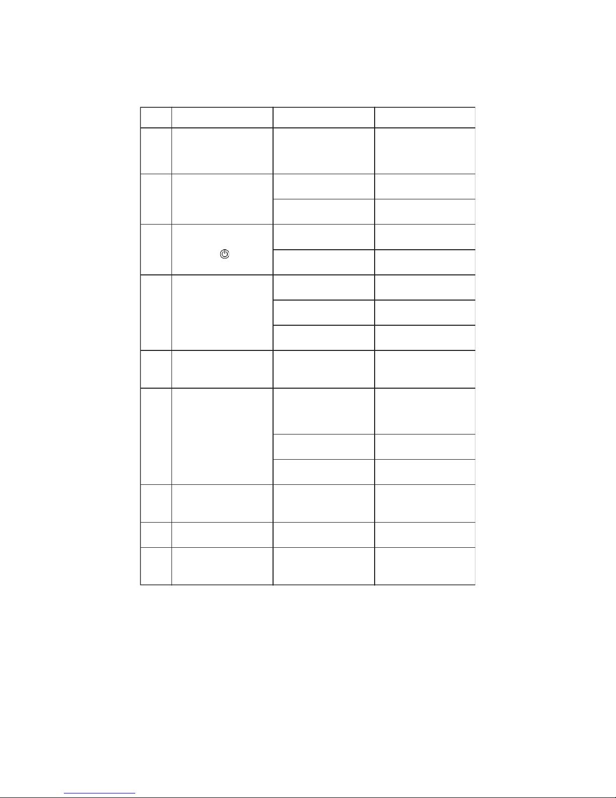
CHAPTER 5
TROUBLESHOOTING
NO. GENERAL TROUBLE POSSIBLE REASON SOLUTION
Power indicator light turns o
1
2
3
4
5
6
7
8
9
No power input
Check the socket external AC
power is available
All functions disable but all
indicator lights is working
Caller ID presentation is not
active
Activate caller ID
The Master number already
exists
Other Master is already set
in the socket
Change Master number or
recover to factory default
setting
GSM indicator light turns o
Can't nd or identify the SIM
card
SIM card not installed properly
The power switch is OFF
Set power to ON mode
Insucient fee of the SIM card Check your account
No power input
Check GSM 158 external AC
power is available
The power switch is OFF
Set power to ON mode
Socket output cannot be
changed by “ “ button
SIM card PIN code is set to
ON mode
Set SIM card PIN code into
o mode
Socket didn't respond to any
operation
GSM 158 wok abnormally
Switch o the power, check
SIM card or reset factory
setting
Network signal weak or
network busy
If mobile phone's signal is
weak too, place the socket at
other place with strong
signal and try again
After power on the socket,
GSM indicator keeps ashing
SIM card PIN code is active
Deactive the SIM card PIN code
SIM card invalid
Contact your respoinsible
telecom company
SMS: “Invalid format. Please
check and try again.”
Invalid command Refer to the user manual
SMS: "No authorization user" Wrong user settings
Use the Master mobile phone
to try the command again
Page 28

- 26 -
CHAPTER 6
MAIN TECHNICAL PARAMETERS
• Input power socket: 110-250V/50Hz,CEE 7/7 Schuko plug
• Output power socket relay: 110-250V/50Hz,230V/30A(30s),
15A long term
• Store temperature: -10°C - +49°C
• Relative humidity: -20°C - +60°C
• Relative humidity: 10-90% without condensation
• Data interface: GSM SIM 1.8V/3.0V socket
• External temperature sensor: -10°C - +50°C
• GSM working band: DCS1800, PCS1900, GSM850, EGSM900
CHAPTER 7
SMS COMMANDS LIST
CATEGORY FUNCTION
Add a Master number
to the socket
#99#phone#code#
Change master password
#04#oldpassword#newpassword#
Change the Master
user's number
#14#Newphone#oldphone#code#
Add a Additional number #06#FamilyNumber#code#
Add several Additional
numbers
#06#Additional Number1#...
#Additional Number4#code#
Delete a Additional number #113#FamilyNumber#code#
Delete several Additional
numbers simultaneously
#113#Additional Number1#...
#Additional Number4#code#
Delete all Additional numbers #113#code#
Switch on the socket output
(manually)
#01#
Switch o the socket output
(manually)
#00#
Enable switching on/o
the output by calling
#18#1#
Disable switching on/o
the output by calling
(Default)
#18#0#
COMMAND NO.
Dene
the users
Switching
on/o
output
1
2
3
4
5
6
7
8
9
10
11
12
Page 29

- 27 -
Delete several Additional
numbers simultaneously
#113#Additional Number1#...
#Additional Number4#code#
Delete all Additional numbers #113#code#
Switch on the socket output
(manually)
#01#
Switch o the socket output
(manually)
#00#
Enable switching on/o
the output by calling
#18#1#
Disable switching on/o
the output by calling
(Default)
#18#0#
Switch on the auxiliary output
#11#1#
Switch o the auxiliary output
#11#0#
Delay switching on
the output after a
certain minutes
#138#1#Minutes#
Delay switching o
the output after a
certain minutes
#138#0#Minutes#
Disable the delay control
#138#0#0#
Set time period to switch
on and o the output
#128#WorkDay#StartTime#EndTime#
Set temperature range
to switch on/o the output
#159#mode#MinTemp#MaxTemp#
Disable auto-control
the output by temperature
#159#00#
Enable auto-command
the output by temperature
#159#01#
Set time period to
switch on the output
#128#WorkDay#StartTime#0#
Set time period to
switch o the output
#128#WorkDay#0#EndTime#
Disable timing
switch on the output
#128#00#
Set limit of temperature
#170#0#LowTemp#HighTemp#
Set limit of temperature
#170#1#LowTemp#HighTemp#
Disable the over-temperature
alarm
#170#00#
Enable the over temperature
alarm
#170#01#
Disable the temperature
rapid changing alarm
#160#0#
Set time period and
temperature changing value
#160#Temp#Time#
Enable the temperature
rapid changing alarm
#160#1#
Enable timing switch
on the output
#128#01#
Switching
on/o
output
Delay
control
Schedule
control
Temperature
control
Over
temperature
control
Temperature
rapid
changing
alarm
Switching
on/o
auxiliary output
7
8
9
10
11
12
13
14
15
16
17
18
19
20
21
22
23
24
25
26
27
28
29
30
31
32
CATEGORY FUNCTION
COMMAND NO.
Page 30

- 28 -
Set temperature range
to switch on/o the output
#159#mode#MinTemp#MaxTemp#
Disable auto-control
the output by temperature
#159#00#
Enable auto-command
the output by temperature
#159#01#
Set limit of temperature
#170#0#LowTemp#HighTemp#
Set limit of temperature
#170#1#LowTemp#HighTemp#
Disable the over-temperature
alarm
#170#00#
Enable the over temperature
alarm
#170#01#
Disable the temperature
rapid changing alarm
#160#0#
Set time period and
temperature changing value
#160#Temp#Time#
Enable the temperature
rapid changing alarm
#160#1#
No SMS notication upon
the power supply changing
#12#0#
SMS notication upon
the power supply
changing (Default)
#12#1#
Temperature
control
Over
temperature
control
Temperature
rapid
changing
alarm
SMS
Notication
"Beep"
warning
tone
Check
Status
Reset to
factory
settings
#19#1#
Enable the "Beep"
warning tone (Default)
#159#
Check "Temperature contorl"
parameters
#160#
Check "Temperature rapidchanging" parameters
#170#
Check "over-Temperature alarm"
parameters
#08#
Reset the socket
#19#0#
Disable the "Beep"
warning tone
#07#
Check socket
operating status
#000#
Check socket
output status
#06#
Check auxiliary
output status
#138#
Check "Delayed switch
on/o the socket"
parameters
#128#
Check "Timed switch
on the socket" parameters
#130#1#
SMS notication upon
the socket output
changing (Default)
#130#0#
No SMS notication upon
the socket output changing
23
24
25
26
27
28
29
30
31
32
33
34
35
36
37
38
39
40
41
42
43
44
45
46
47
CATEGORY FUNCTION
COMMAND NO.
Page 31

Page 32

Manufacturer:
QUANTRAX Kft.
Fülemüle u. 34., Szeged, H-6726, Hungary
Phone: +36 62 424 133 • Fax: +36 62 424 672
E-mail: [email protected]
Web: www.quantrax.hu • www.computherm-hungary.hu
Origin: China
The
COMPUTHERM
GSM 158 type GSM-controlled
socket complies with the requirements of standards
EU EMC 2004/108/EC; LVD 2006/95/EC;
R&TTE 1999/5/EC and RoHS 2011/65/EU.
 Loading...