

Page 1
Computer Weld Technology, Inc.
10702 Old Bammel N Houston Rd.
Houston, TX 77086
Phone: (713) 462-2118
Fax: (713) 462-2503
Email: [email protected]
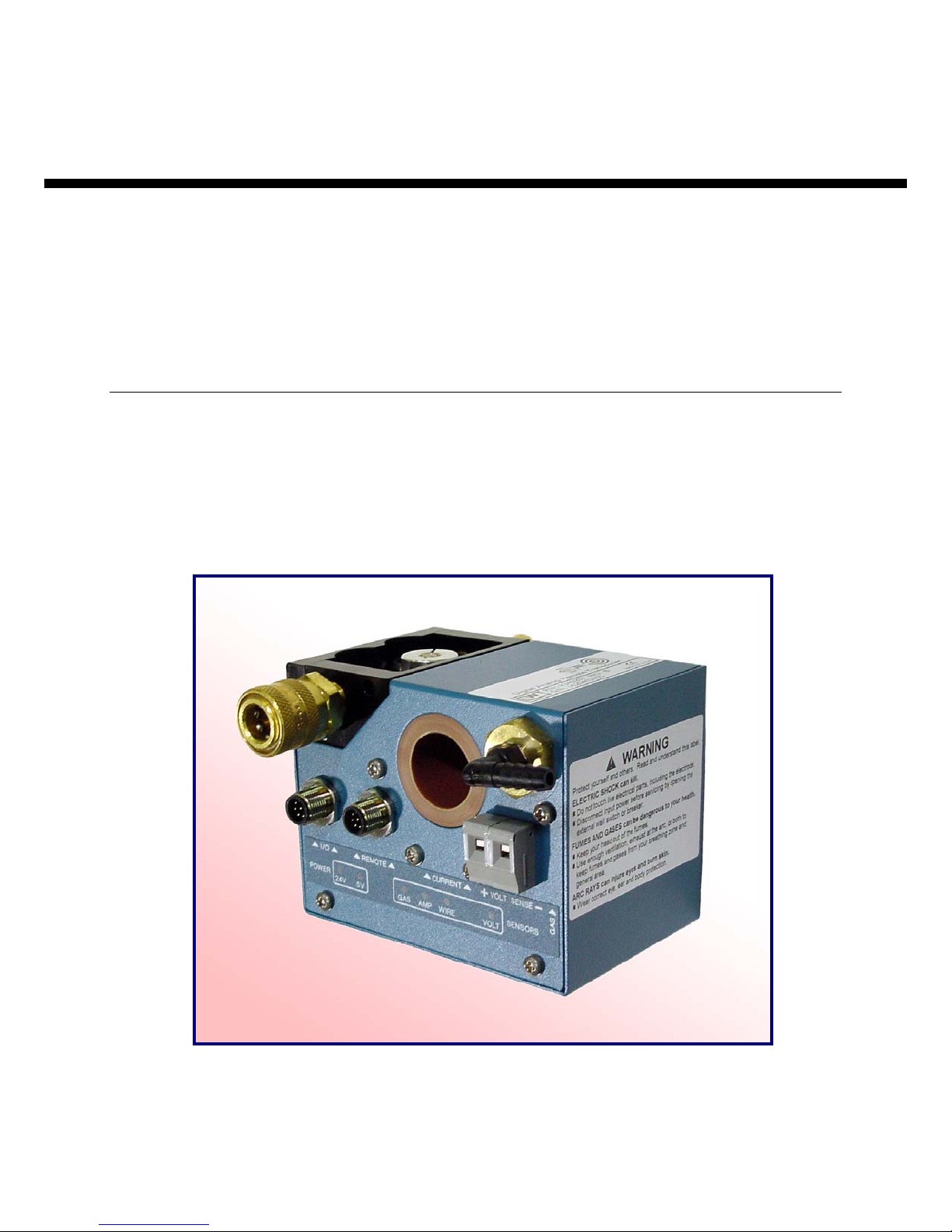
Micro ADM
Micro Arc Data Monitor
Operation / Installation Manual
Manual Part Number: A8M5022
Revised: 7/24/2008
Page 2

Page 3

Table of Contents
1.0 SYSTEM OVERVIEW .................................................................................................... 1
1.1 GENERAL OVERVIEW.............................................................................................................................. 1
1.2 GENERAL SPECIFICATIONS...................................................................................................................1
1.3 SENSOR SPECIFICATIONS..................................................................................................................... 2
2.0 INSTALLATION.............................................................................................................. 3
2.1 GENERAL GUIDELINES............................................................................................................................ 3
2.2 SENSOR INSTALLATION GUIDELINES..................................................................................................4
2.3 CONFIGURE MODBUS™ DEVICE ID .................................................................................................... .5
3.0 OPERATION................................................................................................................ ....6
3.1 ARC DETECTION.................................................................................................................. .....................6
3.2 EMBEDDED FIRMWARE...........................................................................................................................6
3.3 HOST SYSTEM SERIAL INTERFACE...................................................................................................... 6
4.0 MICRO ADM™ MODBUS MEMORY MAP.................................................................... 8
4.1 GENERAL DESCRIPTION......................................................................................................................... 8
4.2 SUPPORTED MODBUS COMMANDS..................................................................................................... 8
4.3 MEMORY MAP FOR SENSOR................................................................................................................. 8
4.4 COIL DEFINITIONS AND OPERATION..................................................................................................11
4.5 REGISTER DEFINITIONS........................................................................................................................12
5.0 MICRO ADM™ ASCII TERMINAL MODE PROTOCOL.............................................14
5.1 GENERAL DESCRIPTION....................................................................................................................... 14
5.2 TERMINAL PROTOCOL.......................................................................................................................... 14
5.3 TERMINAL COMMANDS.........................................................................................................................16
6.0 MICRO ADM™ REMOTE I/O USER INTERFACE...................................................... 19
6.1 GENERAL DESCRIPTION....................................................................................................................... 19
6.2 OPERATIONAL DESCRIPTION........................................................................................................ ......20
6.3 SETTING PROCESS CONTROL LIMITS...............................................................................................21
APPENDIX A MICRO ADM™ INSTALLATION SPECIFICATIONS................................ 23
A.1 MICRO ADM™ SENSOR MOUNTING DIMENSIONS.......................................................................... 23
A.2 SENSOR CABLES AND WIRE SPEED SENSOR INSTALLATION..................................................... 24
A.3 POSITIVE WELDING CABLE INSTALLATION......................................................................................24
A.4 GAS PRESSURE HOSE INSTALLATION..............................................................................................25
A.5 VOLTAGE SENSOR INSTALLATION.....................................................................................................25
A.6 SINGLE UNIT INSTALLATION................................................................................................................26
A.7 MULTIPLE UNIT NETWORK INSTALLATION.......................................................................................28
A.8 NETHUB MOUNTING DIMENSIONS.................................................................................................. 31
A.9 COMMUNICATIONS CABLE P/N: A3W0327......................................................................................... 32
A.10 REMOTE I/O CABLE P/N: X3W5102......................................................................................................32
A.11 TYPICAL EXTERNAL POWERED PLC I/O SYSTEM INTEGRATION................................................33
A.12 TYPICAL SENSOR POWERED PLC I/O SYSTEM INTEGRATION....................................................34
A.13 NORMAL WELD CYCLE PROCESS CONTROL FLOW CHART........................................................ 35
A.14 GROUP WELD CYCLE PROCESS CONTROL FLOW CHART...........................................................36
A.15 LEARN WELD CYCLE PROCESS CONTROL FLOW CHART............................................................ 37
Page 4

APPENDIX B MICRO ADM™ ASSEMBLY PARTS LIST................................................38
B.1 MICRO ADM™ SENSOR ASSEMBLY P/N: A3A0226 REV: 0............................................................. 38
B.2 MICRO ADM™ SENSOR ASSEMBLY P/N: A3A0226 REV: A............................................................. 41
B.3 MICRO ADM™ SENSOR ASSEMBLY P/N: A3A0226 REV: B............................................................. 44
B.4 MICRO ADM™ SENSOR ASSEMBLY P/N: A3A0226 REV: C.............................................................47
APPENDIX C SCHEMATIC DIAGRAMS .......................................................................... 50
C.1 MICRO A DM™ SENSOR ASSEMBLY P/N: A3A0226 REV: 0.............................................................50
C.2 MICRO A DM™ SENSOR ASSEMBLY P/N: A3A0226 REV: A............................................................. 51
C.3 MICRO A DM™ SENSOR ASSEMBLY P/N: A3A0226 REV: B............................................................. 52
C.4 MICRO A DM™ SENSOR ASSEMBLY P/N: A3A0226 REV: C.............................................................53
APPENDIX D DEVICE ID MSB AND LSB DECODE TABLE.......................................... 54
Page 5

1.0 SYSTEM OVERVIEW
1.1 General Overview
The Micro ADM™ Sensor (A3A0226) is a lightweight; compact, multi-sensor unit
designed for monitoring, Parameter Testing and telemonitoring service purposes
in a welding environment. The Micro ADM™ Transducer includes an embedded
micro-controller to provide the necessary data acquisition, signal processing and
communications firmware to allow remote logging/testing of the following basic
welding parameters.
Arc Current
Arc Voltage
Wire Feed Speed
Shielding Gas Pressure
The light weight, easy to install design allows the user to install the Micro ADM™
at the wire drive motor inlet using industry standard quick disconnect conduit
fittings or to a fixed surface with the optional mounting brackets (A2A0025). The
LED indicators provide the operator or maintenance personnel with a quick visual
indication of sensor activity.
The unit is powered by a user supplied external 24 VDC power source via the
sensor interface cable (A3W0327). This cable also provides an RS-485 FullDuplex serial communications port to an external system (data acquisition or
PLC). A second Remote I/O cable (X3W5102) is provided to allow an external
PLC/Robotic controller to control and monitor the sensors’ embedded fault
testing routines.
1.2 General Specifications
Listed below are the g
Dimensions: 3.81” H x 5.38" W x 5.25" L (97mm x 137mm x 133mm)
Weight: 2.7 lbs (1.2 kg)
Power Input: 24 vdc @ 0.2 amp, ripple 200 mv
Operating Temp: -12°C to +60°C
Remote Input: 5 – 24 vdc @10ma current limited
Remote Outputs: Non isolated 24 vdc @ 75 ma Sourcin g Open emitte r
Serial Communication Modbus™ RTU slave mode protocol
eneral system specifications:
Transistor output with current limit
1
Page 6

1.3 Sensor Specifications
Current Sensor
Current range 0-600 A (DC)
Relative precision on Range ± 1%
Max Linearity error ± 0.9 % of reading
Band Width at ±1db 2.5 Khz
Voltage Sensor
Voltage range 0-100 V (DC)
Relative precision on Range ± 1%
Max Linearity error ± 0.5 % of reading
Band Width at ±1db 2.5 Khz
Pressure Sensor English Units Metric Units
Pressure range 2.5 – 14.5 PSI 15 – 100 Kpa
Relative precision on Range ± 3% ± 3%
Max Linearity error ± 1.8 % of rea ding ± 1.8 % of reading
Band Width at ± 1db 250 Hz 250 Hz
Wire Speed Sensor English Units Metric Units
Wire diameter (min/max) .030 - .062 inch 0.8 mm / 1.6 mm
Speed range 10 – 1000 i pm 4 – 420 mm/s
Relative precision on Range ± 3% ± 3%
2
Page 7

2.0 INSTALLATION
2.1 General Guidelines
The Micro ADM™ can be mounted two different ways. It can be installed at the
wire feeder using the quick disconnect fittings or mounted to a fixed surface.
Listed below are some things that should be taken into consideration when
selecting a place and method for mounting of the Micro ADM™:
Mount the Micro ADM™ in a location that is convenient for
installation of the welding wire and will not cause any binding
of the wire or the wire liner. It is recommended that the
Micro ADM™ be mounted as close to the wire feeder as
possible (not to exceed 1 meter).
The Positive welding cable must pass through the Micro
ADM™ sensor opening. Make sure that there is no stress on
the sensor as a result of movement of the welding cable.
The Shielding Gas line must be attached to the gas inlet of
the sensor. Consideration must be given to the routing of the
Shielding Gas hose to prevent any restriction of gas flow.
The Sensor cable must be mounted in such a manner as to
prevent stress on the sensor cable connector.
The two 18 gage conductors supplied with the Micro ADM™
are used to provide the + and – of the Voltage Sense. These
conductors must be routed so as not to produce stress on
the Voltage Sense terminal strip.
When mounting the Micro ADM™, position it so the operator
or maintenance personnel can see the sensor LEDs if
possible.
If using the optional mounting brackets to mount the Micro
ADM™, an insulating liner must be used for support of the
wire from the sensor to the back of the wire feeder inlet
guide.
3
Page 8

2.2 Sensor Installation Guidelines
Installation of the Micro ADM™ is a simple 5-step process regardless of the
selected mounting method.
1. Feed the Positive welding cable through the Micro ADM™ Current
Sensor opening. The diameter of the opening will accommodate a 22
mm cable. If the crimp terminal is too large to fit through the opening
then it must be removed and another terminal installed after the cable
is passed through the opening.
2. Feed the wire through the Micro ADM™ Wire Feed Speed Sensor
inlet. Push down on the pressure release lever located on the top of
the sensor while feeding the wire through the guide rollers and out the
other side of the sensor. Feed the wire into the wire drive motor as
you would normally. If using the quick disconnect fittings to mount the
sensor, connect one end to the wire drive motor quick disconnect
fitting. Insert the wire liner quick disconnect fitting into the other end of
the sensor. If using the optional mounting brackets, install the
sensor at the desired location. Install an insulated wire liner or conduit
assembly (Maximum length of 1 meter) for support of the wire from the
Micro ADM™ to the wire feeder inlet.
3. Connect the Shielding Gas line to the Micro ADM™ Gas inlet. A barb
T-fitting is provided to facilitate the installation of the Gas Line. Cut the
Gas hose and install each end on to the 1/8” NPT 90° elbow. User to
supply the necessary adaptor. Make sure to check for gas leaks after
the hose clamps are installed.
4. Use the two Conductors (18 gage, 600V) provided with the Micro
ADM™ Sensor to connect the Micro ADM™ Voltage Sensor to the
welding system. Route the RED conductor (3’ long) from the Positive
(+) terminal of the Voltage Sense Terminal block to the Positive
welding cable connection point (at the Torch or Wire Feeder). Route
the BLACK conductor (25’ long) from the Negative (-) terminal of the
Voltage Sense Terminal block to the Negative welding cable
connection point (at the Work piece ground point).
5. To connect the Sensor Cable (A3W0327) to the Micro ADM™, insert
the connector into the Micro ADM™ Sensor Cable receptacle until it
“Clicks” and locks into place. Connect the other end to the appropriate
weld data acquisition system or PLC. To remove the Micro ADM™
Sensor Cable, pull back on the locking barrel of the connector plug
while pulling the plug from the receptacle. A diagram of the
connections for the cable can be found in Appendix B.
4
Page 9

2.3 Configure ModBus™ Device ID
Two BCD switches are provided to allow external definition of 0 to 247
ModBus addresses. Prior to operation the user must set the desired
Device ID number for the ModBus communications. Each address must
be unique. To set the Device ID remove the Black hole plug from the
bottom of the unit. Locate the LSB and MSB rotary switches. Set the
binary address by rotating the switches to the desired address. The
Switch is Binary encoded and has a range of “0 - F”. Reinstall the hole
plug after setting the Device ID number. The maximum Device ID is
restricted to 247 as specified by the ModBus Protocol standard. See
Appendix D for Device ID MSB and LSB Decode Table.
5
Page 10

3.0 OPERATION
3.1 Arc Detection
“Auto Arc On” is not available if firmware is Version 2.31 and later.
If the “Auto Arc On” mode is enabled the sensor will use the Arc Voltage and
Current to determine when to log welding data. Both parameters must exceed
the user defined threshold values to set an “Arc On” condition. When the Voltage
or Current falls below the user specified value the sensor would set an “Arc Off”
condition and stop data logging. The user must activate this input by setting the
corresponding mode via the serial communication port.
If the “Auto Arc On” mode is disabled the user can force a arc on condition by
asserting the “Remote Arc On” input. This signal is the “Black” wire provided in
the sensor serial communication cable P/N A3W5042. Asserting a 5-24 VDC
signal from the common (Grey) and the remote arc on input (Black) will force a
sensor arc on condition.
3.2 Embedded Firmware
The embedded firmware has basic scaling and averaging capabilities as well as
Slave mode ModBus RTU Communications protocol support. The sensor will
provide user defined average and data collection mode to allow Run time and/or
average data storage. The Run time data will be generated based on the
averaging sample time specified by the user. The Raw analog data will be
sampled at a 5 kHz rate. The Sensor will average 5 samples to produce a 1khz
data rate for all analog sensors. The Wire feed conversion time will be based on
the actual wire feed rate (16.6 Hz – 16.6 KHz).
Configuration of scaling and averaging parameters will be possible through the
ModBus network port. The user may specify the number of samples (X) to be
averaged before saving the data point in memory for later play back. The
SENSOR will also generate a weld summary for each weld, which will be the
average of all sampled data during the last weld cycle. The Data will be
Date/Time stamped and stored in NV-RAM. Up to 1300 weld summaries may be
stored before downloading. The sensor provides continuous averaging of the X
most recent data values, and queries by the host system at lower frequencies of
either last data value or last average value.
3.3 Host System Serial Interface
The senso
r will provide a RS-485 compatible serial port and will support the
ModBus RTU protocol. The Sensor default baud rate is 19.2K Baud.
6
Page 11
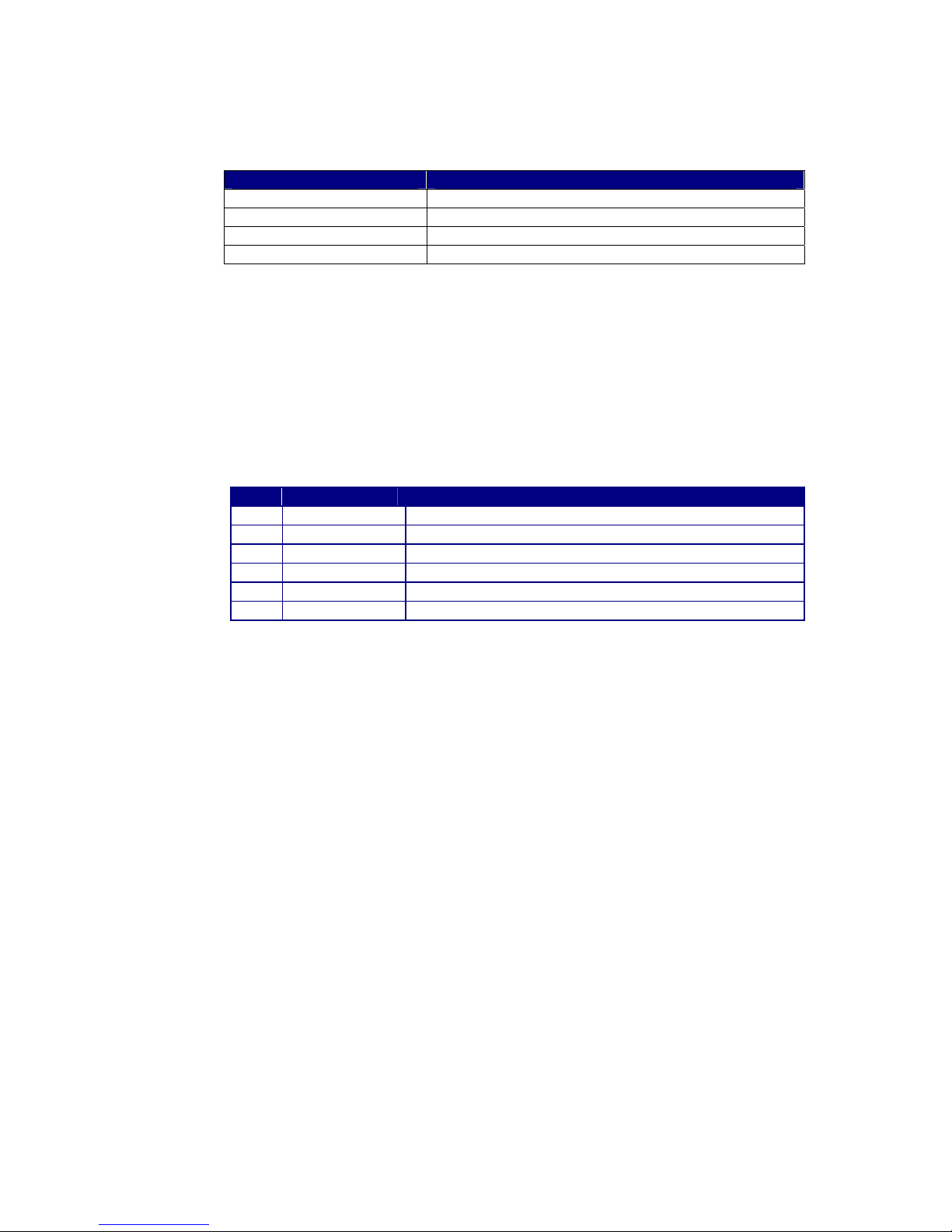
The following is the general specification for the RS-485 port:
Serial Port Specification Description
Physical support Twisted Pair
Connector Turck Eurofast 5 pin circular
Network RS 485 – Full Duplex
Data exchange protocol Modbus RTU
The RS-485 is a Turck Eurofast connector and will provide the RS-485
connections and the power to operate the sensor. The sensor provides a user
configurable 120-ohm termination resistor for the RS-485 serial cable. The Host
controller will provide the necessary power to operate the sensor. The power will
be connected to the sensor through the RS-485 cable. The sensor requires an
input voltage of 12 – 36 Vdc @ 3.6 watts. The sensor will provide polarity and
over current protection. The sensor terminal connector Pin out is as follows:
Pin Wire Color Function
1 Brown Sensor (12 – 24 vdc) Positive Input
2 White Net_High RS-485 Signal High
3 Blue Net_Low RS-485 Signal Low
4 Black Remote Arc Active Input (5 – 24 vdc)
5 Grey Sensor (12 – 24 vdc) Com mon
Shield Sensor Cable Shield – Not Connected at Sensor
7
Page 12
4.0 Micro ADM™ MODBUS MEMORY MAP
4.1 General Description
This document provides the basic ModBus memory map and command structure
for the Micro ADM™ RS-485 communications port. The Micro ADM™ supports
the ModBus Protocol as specified in the Modicon Technical publications
“ModBus Protocol” (intr7.html). The Micro ADM™ control does not support the
Broadcast mode. The controller provides the slave side communications routines
for the RTU mode. The user must define the Slave ID to a unique ID number
from 1 – 247. Default Baud rate is 19.2 K baud.
4.2 Supported ModBus Commands
The following ModBus commands are supported:
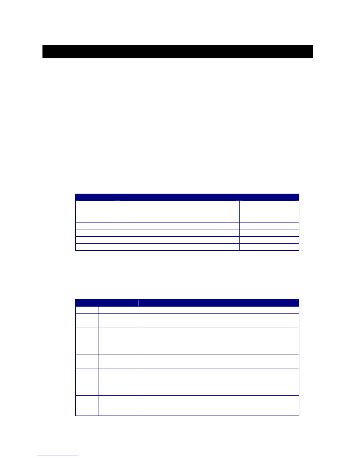
CODE DESCRIPTION ADDRESS RANGE
01 Read Coil Status 0-15
03 Read Holding Registers 0-26
05 Force Single Coil 0-15
06 Preset Single Register 0-26
15 Force Multiple Coils 0-15
16 Preset Multiple Registers 0-26
17 Report Slave ID 5 bytes
4.3 Memory Map for Sensor
The following is the Coil definitions address 0-15:
COIL ADDRESS DESCRIPTION
1 0 Arc Active – Set when Weld Arc is detected
2 1 Save Average Data – When set Weld Summary Data is stored
in NVRAM
3 2 Clear Summary Counter – When set the Average Data Counter
is reset to 0 and Average Memory is cleared
4 3 Clear Part Fault Counter – When set the Fault Counter will be
reset to 0
5 4 Enable Metric units of measure. When set the sensor use
metric units of measure. (Wire = mm/sec; Gas = kpa)
6 5 Enable Auto Arc Detect – When set the Arc On condition is
detected by sensing the arc voltage and arc current. When
cleared the sensor can be forced into an arc on con dition by
asserting CR 1.
7 6 Read Memory – When set the Weld Summary data specif ied
by Register 19 will be read into Register 2-12. Coil will be reset
when summary has been loaded. Function is executed only
8
Page 13

when the arc
is off.
8 7 Set Clock – When set the Date and Time values set in Re gister
7 – 12 will be loaded to the Real Time Clock. The Coil will be
reset after the RTC is set. This function wil l only execute when
the arc is off.
9 8 Learn Mode Enabled – When set the user defined Le arn input
is active.
10 9 New Part Enabled – When set the user New Part Inp ut is
active.
11 10 AAD Fault – When set the sen sor has detect ed an
Accumulated Arc Density Fault condition. This output will only
be set when the weld is complete or when the pa rt input is
cleared.
12 11 TIME Fault – When set t he senso r has determined a n arc time
fault has occurred. If set when the Part input is cleared the
sensor indicates an accumulative arc time fault for the part.
13 12 VOLT Fault – When set the sensor has detect ed a volt
parameter fault during the previous weld. If set when the Part
input is cleared it indicates an arc density fault has oc curred.
14 13 AMP Fault – When set the sen sor has detect ed an amp
parameter fault during the previous weld. If set when the Part
input is cleared it indicates an arc density fault has oc curred.
15 14 GAS Fault – When set the sen sor has detect ed a gas pre ssure
fault during the previous weld.
16 15 WIRE Fault - Wh en set the se nsor has de tected a wi re speed
parameter fault during the previous weld. If set when the Part
input is cleared it indicates a total volume appli ed fault has
occurred.
The following is the Register definitions address 0-26:
REGISTER ADDRESS DESCRIPTION
1 0 Arc On Status – When the arc is active the value will be
greater then 1. When the arc is off the value will be 0
2 1 Arc Time – Weld on timer in 0.1-second intervals. Value is
incremented during a weld cycle and measures the A rc On
time for each weld. When the weld cycle is complet e the
total time for the weld will be set. (Note 100 = 10.0 sec)
3 2 Volts – During the Arc on Time the valu e represents the
actual arc voltage. The value is in 0.1-volt increments
(100=10.0 volts). When the weld cycle is compl ete the
value will be the statistical average for the last weld.
4 3 Amps- – During the Arc on Time the v alue represent s the
actual arc current. The value is in 1amp increm ents
(100=100 amps). When the weld cycle is co mplete the
value will be the statistical average for the last weld.
5 4 Gas Pressure - – Du ring the Arc on Time the val ue
represents the actual gas pressure. The value is in 0.1 PSI
or 1KPa increments (100=100Kpa/10.0 PSI). When t he
weld cycle is complete the value will be th e statistical
average for the last weld.
6 5 Wire Speed - – During t he Arc on Tim e the value
represents the actual wire feed speed. Th e value is in 1-
9
Page 14

c increments (100=100 MM/Sec/100 IPM). When
mm/se
the weld cycle is complete the value will be the statistical
average for the last weld.
7 6 RTC BCD SEC:MIN – T he value is the a rc start SEC: MIN
based on the Real Time Clock. This value is set when a n
arc on condition is detected. (MSB = seconds; LSB =
Minutes)
8 7 RTC BCD HR:DAY - The va lue is the arc start Hour and
Day based on the Real Time Clock. This value is set when
an arc on condition is detected. (MSB = Hour; LSB = Day)
9 8 RTC BCD MN:YR - The valu e is the arc start Month and
Year based on the Real Time Clock. This value is set wh en
an arc on condition is detected. (MSB = Month; LSB =
Year)
10 9 Arc Time Mean – Arc Time mean value for in-pro cess li mits
11 10 Arc Voltage Mean – Voltage mean value used for in-
process limits.
12 11 Arc Current Mean – Amperage mean value used for in-
process limits.
13 12 Gas Pressure Mean – Gas pressure mean value used for
in-process limits.
14 13 Wire Spee d Mean – Wire sp eed mean value used fo r in-
process limits.
15 14 Spare – Not Used
16 15 Weld Count – Total number of weld sinc e last reset. If weld
counter reaches the max count of 655 35 the counte r will
reset to 0.
17 16 Weld Summa ry Count – Value indi cates the numb er of weld
summaries stored in memory (Max Count = 500 ).
18 17 Part Fault Co unter – Total nu mber of faulted part s since last
fault count reset.
19 18 Read Weld Number – the value is used to select the sto red
Summary data to be read from memory to Register 2-1 2.
Range of Value 1-500.
20 10 Arc On Amps – The value set in this Register is the welding
current that must be exceeded to establi sh an arc on
condition. Value is in 1-amp increments (10 = 10 amp s).
21 20 Arc On Volt s – The value set in this Regi ster is the weldi ng
voltage that must be exceeded to establish an arc on
condition. Value is in 0.1-volt increments (100 =10.0 v olts).
22 21 SAMPLE COUNT: TIME Sigma – Th e MSB byte indicates
the number of raw data samples to av erage to produce a
single sample value as stored in Register 3-5. T he LSB
byte sets the Arc Time sigma value used by sensor for
process limits Setting the Sigma value to 0 will disable the
test function. (Arc Time Sigma = LSB/24; i.e. 55 =2.29)
23 22 VOLT: AMP Sigma – Th e MSB byte sets the Volt age sigma
value used by the sensor for process limits. The LSB byte
sets the Amp sigma value used by sensor for process limits
Setting the Sigma value to 0 will disable the test function.
(Sigma = MSB, LSB/24; i.e. 55 =2.29)
24 23 GAS: WIRE Sigma – The MSB byte sets the Gas Pressure
sigma value used by the sensor for process limits. The
LSB byte sets the Wire Speed sigma value used by sensor
for process limits. Setting the Sigma value to 0 will disable
10
Page 15
t function. (Sigma = MSB, LSB/24; i.e. 55 =2.29)
the tes
25 24 DENSITY: VOLUME Sigm a – The MSB byte sets the Arc
Density sigma value used by the sensor for process limits.
The LSB byte sets the Weld Volume sigma value used by
sensor for process limits. Setting the Sigma value to 0 will
disable the test function. (Sigma = MSB, LSB/24; i.e. 55
=2.29)
26 25 DELAY: WELDS – The MS B byte sets the start/end Test
delay time. The value is in 0.1 second increment s and sets
the delay time from arc start to begin testing and the e nd
time, prior to arc off, to stop testing. The LSB indicates the
number of welds per part. This value is set duri ng the le arn
mode.
The following is a summary of the Report Slave ID and Status (Code 17)
Response Data fields:
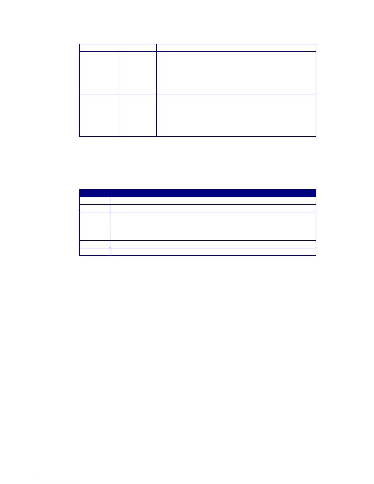
Byte Contents
1 Sensor ID Number =10 Hex (Version 1, Rev0)
2 Run Indicator (0=OFF, F F=On)
3 Status Byte Bit 0 = Ram Full
Bit 1 = Battery Ok
Bit 2 = Self Test Ok
Bit3-7 = 0
4 Firmware Version Number – BCD Format (MSB = Major: ISB = Minor)
5 Firmware Version Number – BCD Format (MSB+LSB = Release)
4.4 Coil Definitions and Operation
The Micro ADM™ has 16 simulated output coils. These coils are used as
internal bit flags to perform specific functions. Only 1-8 of the simulated coils is
used. Setting the coils 8-16 will not have any effect on the Micro ADM™
controller. However, they are reserved for future expansion. The Micro ADM™
supports both single and group force coil commands. Refer to Section 4.3 for
summary of the Coil functions.
To clear the Micro ADM™ weld and average counters or reset the total arc timer,
force the specific coil to the “ON” condition. The Micro ADM™ will clear the
requested counter or timer and then reset the coil to the “OFF” condition
signifying a successful operation.
To disable the auto arc on detection mode force coil 2 to the “ON” condition.
When set the Micro ADM™ will only log data when the remote on input is active.
To allow normal arc on detection Coil 2 must be in the “OFF” condition.
To set the Real time clock perform the following steps:
11
Page 16

1. Set Coil 2 to the “ON” condition to disable automatic arc detection.
2. Load the BCD formatted Time and Date into the value Registers 6-12.
3. Set Coil 8 to the “ON” condition. The Micro ADM™ will clear the coil
after completing the function.
4. Enable Coil 2 to resume automatic arc detection.
To read a stored weld data summary perform the following steps:
1. Set Coil 2 to the “ON” condition to disable automatic arc detection.
2. Load the desired weld summary number int o Registers 19. This value
must be equal to or less than the total number of saved welds as
indicated by Register 17.
3. Set Coil 6 to the “ON” condition. The Micro ADM™ will load the stored
data into Registers 2-12 and will clear the coil after completing the
function. The data will remain in the register until the next arc on or
stored weld request.
4. Enable Coil 2 to resume automatic arc detection.
4.5 Register Definitions
Register 1: Used to indicate when a welding arc has been detected. When this
register is a 1 the Micro ADM™ controller is updating the welding parameters
with new measured values.
Register 2–6: Contains the current value for each of the welding parameters:
The following table shows the value and units of measure for each weld
parameter register:
REGISTER MEASURED PARAMETERS UNITS OF MEASURE
2 Arc On time – Time in 0.1 seconds from arc
detection
3 Arc Voltage – Voltage measured by Volt sensor (Value/10) vdc
4 Arc Current – Welding amps measured by
Hall Sensor
5 Gas Pressure – Shielding Gas pressure from
Torch
6 Wire Speed – Linear wire speed measured by
encoder
(Value /10) sec.
Value = Amps DC
(Value * 0.1)=Kpa (psi)
Value = mm/sec (ipm)
12
Page 17

When the Arc is in the off condition the Registers will display the statistical
average for the last weld.
Registers 7-9: Contains the BCD coded Time and Date at the start of the last
weld. These registers will only update when a new weld is detected or a weld
summary is loaded from memory. The Time and Date parameters are in BCD
format. The low nibble is the 1’s units and the upper nibble is the 10’s units.
Note: When setting the Real time Date and Time the values loaded into the
Registers 7-9 must be in a BCD format.
Register 10–14: Used to indicate the statistical mean values as calculated
during the Learn Mode for each weld within the learned part. The value is an
integer value and represents mean value that is used with the sigma value to set
the upper and lower control limits for parameter testing. These values have the
same scaling as Register 2-6 (see above table).
Register 15: Spare Register - Not used at this time.
Register 16: The current weld count since the last weld count reset. This
counter is incremented when the total arc time for a weld is greater then 0.5
seconds. This prevents false arc starts from being counted as a valid weld.
Register 17: Indicates the number of weld summaries stored in the weld
memory. The maximum number of welds stored is 1024. Writing a new value to
this register will cause the next collected weld to be written to that weld number
location. The Welds will only be saved if the Save Weld summary coil (2) has
been set and the minimum weld time is greater than 0.5 seconds.
Register 18: This register sets the number of raw data points to be averaged to
generate a single sampled value. The minimum value is 1 and the maximum
value is 255. Setting this value to 0 will disable the Analog Data collection
routines.
Register 19: This register is used to read a previously stored weld summary
from memory. Set the desired weld summary number in this register then set the
Read Weld Memory Coil 7. The value will be written to Register 2 – 12.
Maximum value is 1024.
Register 20-21: These registers are used to specify the conditions required to
establish an arc on signal. To set the auto arc on signal the Voltage and current
sensor values must exceed both values stored in the these registers. If any
single sensor input drops below this level the arc on signal will be reset.
Register 22-26: These registers are used to specify the process control limits
used for in process monitoring. The MSB and LSB bytes are used as
independent byte size variables and have a Byte size decimal range of 0-255.
13
Page 18

5.0 Micro ADM™ ASCII TERMINAL MODE PROTOCOL
5.1 General Description
If the Device ID is set to zero when the power is applied then the Micro ADM
Terminal mode is active and can be used to off-line program the user
configurable parameters and operating modes. The protocol is a simple ASCII
command string that allows the user to upload or download the various data.
The user can use any terminal program to perform the programming function. All
program command functions are case sensitive. The serial port is configured for
the following data format:
Baud Rate: 19.2K, Full Duplex
Word Length: 8 Data Bits, One Stop and no parity
Hand Shaking: None
5.2 TERMINAL PROTOCOL
The protocol consists of a command string and optional data bytes. The
command string is an alpha character and an option number followed by a "=" or
"?", followed by optional data and terminated with an ASCII "cr" (0dh). The "="
will indicate that data is being sent to the selected parameter by the host
controller. The "?" will indicate a request for data from the Micro ADM to the
host controller. If the host is sending data to the Micro ADM the data will be
placed after the "=" character and will be an ASCII string terminated with an
ASCII "cr" (0dh). The following is an example of reading a parameter value from
the Micro ADM™:
From Host type: V1? (cr)
Response from Micro ADM™: ##
Where: ## is the current value for the parameter and
The following is an example of how to modify a value in the Micro ADM™ using
the terminal commands:
From Host type: V1=#### (cr)
Where: ## is the new value for the parameter and
(cr) is the enter key
(cr) is the enter key
14
Page 19

The following is a summary of the two special command functions. They are
used to set and read the Micro ADM™ Real Time Clock (RTC). To read the
current Time type the following command:
From Host type: T? (cr)
Response from Micro ADM™: hh:mm:ss
Where: hh is the current hour, mm is the current
minute and ss is the current second. (cr) is
the enter key
To set the time (hour/minute/second) type: T=10:17:35 (cr) Entire field must be
completed as explained below:
Type 6:45 am as T=06:45:00 (cr)
Type 7:25 PM as T=19:25:00 (cr)
Note: “cr” denotes carriage return (Enter)
To read the current Date type the following command:
From Host type: D? (cr)
Response from Micro ADM™: mn:dd:yy
Where: mn is the current month, dd is the current
day and yy is the current year, (cr) is the
enter key
To set the date (year/month/day) type: D=99/06/01 (cr). The Entire field must be
completed as explained below:
Type February 4, 1999 as D=99/02/04(cr)
Type November 23, 2000 as D=00/11/23(cr)
Note: “cr” denotes carriage return (Enter)
15
Page 20

5.3 TERMINAL COMMANDS
The following is a summary of the Terminal Commands supported by the Micro
ADM:
Command DES CRITION RANGE
C0 Voltage zero offset calibration value. (128 = 0 offset)
Negative offset < 128 > Positive offset
C1 Current zero offset calibration value (128 = 0 offset)
Negative offset < 128 > Positive offset
C2 Gas Pressure zero offset calibration value (128 = 0
offset)
Negative offset < 128 > Positive offset
C3 Gas pressure Gain value (Gain = Value/32) 0-255
D Sets or re ads the Real Time Clock date pa rameters
Format = YY/MM/DD
T Sets or Reads the Real Time Clock Time parameters
Format = HH:MM:SS
M0 ModBus Coils 1-8 Set/Read. Binary Bit’s are set by
decimal value. CR1=1, CR2=2, CR3=4, CR4=8,
CR5=16, CR6=32, CR7=64, CR8=128
M1 ModBus Coil s 9-16 Set/Read . Binary Bit’s are set by
decimal value. CR1=1, CR2=2, CR3=4, CR4=8,
CR5=16, CR6=32, CR7=64, CR8=128
M2 Baud Rate – Sets th e serial co mmunications B aud
Rate 0=38.4Kb, 1=19.2Kb, 2=9600buad, 3=4800 baud
M3 Sample Co unt – Numb er of raw sample s to averaged
for a single parameter sampl e
M4 Voltage Sigma value. When set to zero parameter
testing is disabled. (Note: Sigma = Value/24)
M5 Amp Sigma value. When set to zero parameter testing
is disabled. (Note: Sigma = Value/24)
M6 Gas Sigma value. When set to zero parameter testing
is disabled. (Note: Sigma = Value/24)
M7 Wire Speed Sigma value. When set to zero parameter
testing is disabled. (Note: Sigma = Value/24)
M8 Arc Density Sigma value. When set to zero parameter
testing is disabled. (Note: Sigma = Value/24)
M9 Weld Volume Sigma value. When set to zero
parameter testing is disabled. (Note: Sigma =
Value/24)
M10 Start/End Test time value. The value specifies the
delay time from Arc On to begin parameter testing and
the time prior to arc off to stop all parameter testing.
M11 Number of welds per Part. This value indicates the
number of welds per part as determine d by the Lea rn
mode.
V1 Arc On Status – When the arc is active the value will be
greater 1. When the New Part input is active, the value
will be the calculated End Test time for the current
weld. When the arc is off the value will be 0
V2 Arc Time – Weld on timer in 0.1-second intervals.
Value is incremented during a weld cycle. And
0-255
0-255
0-255
8 Bytes
8 Bytes
0-255
0-255
0-3
0-255
0-255
0-255
0-255
0-255
0-255
0-255
0 – 25.5
0-65535
0-65535
16
Page 21

measures
the Arc On time for each weld. When the
weld cycle is complete the total time for the weld will be
set. (Note 100 = 10.0 sec)
V3 Volts – During the Arc on Time the value represents
0-102.3
the actual arc voltage. The value is in 0.1 volt
increments (100=10.0 volts). When the weld cycle is
complete the value will be the statistical average for th e
last weld.
V4 Amps- – During the Arc on Time the value represents
0-1023
the actual arc current. The value is in 1amp
increments (100=100 amps). When the weld cycle is
complete the value will be the statistical average for th e
last weld.
V5 Gas Pressure - – During the Arc on Time the value
0-2032
represents the actual gas pressure. The value is in
1KPa increments (100=100KPa). When t he weld
cycle is complete the value will be the statistical
average for the last weld.
V6 Wire Speed - – During the Arc on Time the value
0-1000
represents the actual wire feed speed. Th e value is in
1-mm/sec increments (100=100 MM/Sec). When th e
weld cycle is complete the value will be th e statistical
average for the last weld.
V7 SEC:MIN – The value is the arc start Second:Minute
0-65535
based on the Real Time Clock. This value is set when
an arc on condition is detected.
V8 HR:DAY - The value is the arc start Hour and Day
0-65535
based on the Real Time Clock. This value is set when
an arc on condition is detected.
V9 MN:YR - The value is the arc start Month and Year
0-65535
based on the Real Time Clock. This value is set when
an arc on condition is detected.
V10 Arc Tim e Mean - This valu e is set during th e learn
0-6553.5
mode for each weld on a part.
V11 Volt Me an - This valu e is set during the l earn mode for
0-102.3
each weld on a part.
V12 Amp Me an - This valu e is set during the l earn mode for
0-600
each weld on a part.
V13 Ga s Pressure Mea n - This value is set during the learn
0-16.0
mode for each weld on a part.
V14 Wi re Speed Mean - This value i s set during the learn
0-1000
mode for each weld on a part.
V15 Spare Re gister – Not Defined 0-65535
V16 Wel d Count – Total number of weld since last reset. If
0-65535
weld counter reaches the max count of 65535 the
counter will reset to 0.
V17 Wel d Summary Count – Val ue indicate s the number of
0-1365
weld summaries stored in memory (Max Count = 500).
V18 Sampl e Count – Value indicate s the number of ra w
0-255
data samples to average to produce a single sample
value as stored in Register 3-5.
V19 Re ad Weld Numb er – the value is u sed to select the
0-1024
stored Summary data to be read from memory to
Register 2-12. Range of Value 1-500.
V20 Arc On A mps – The value set in this Regi ster is the 0-1023
17
Page 22

ding current that must be exceeded to establish an
wel
arc on condition. Value is in 1-amp increment s (10 =
10 amps).
V21 Arc On V olts - The valu e set in this Regist er is the
welding voltage that must be exceeded to est ablish an
arc on condition. Value is in 0.1-volt increment s (100
=10.0 volts).
0-102.3
18
Page 23

6.0 Micro ADM™ Remote I/O User Interface
6.1 GENERAL DESCRIPTION
The Micro ADM™ AAD interface is comprised of three 24 VDC inputs and three
24 VDC sourcing outputs. INP1 “Learn” input is used to invoke a learn mode for
the Micro ADM™. This input will allow the Micro ADM™ to monitor multiple parts
and to establish the necessary control limits that will be used to verify production
parts. The Micro ADM™ uses Accumulated Arc Density (AAD) to validate the
welds and assure conformance to the base-line sampled group of parts.
The INP2 “Part” input is configured to allow the user to indicate when a part is
being welded. This input must be asserted during the complete part cycle. The
Micro ADM™ uses this input to establish when a new part is being welded.
When the input is cleared the Micro ADM™ will perform a final analysis of all the
welds made and set the pass/fail Part output signals. The pass-fail outputs will
be set based on weld volume, weld counts and work-applied calculations.
The optional INP3 “Group B” input can be used to separate two weld groups
within a single Part. When invoked the Group input signals the completion of the
“Group A” welds and the start of the “Group B” welds. This input must be
asserted during the complete “Group B” weld cycle. The Micro ADM™ uses this
input to establish when the first “Group A” welds have been completed and the
beginning of the “Group B” welds. When the input is asserted the Micro ADM™
will perform a final analysis of the entire first “Group A” welds and will assert the
pass/fail Part output signals. The “Group A” pass-fail outputs will be set based
on total weld volume, weld counts and total work applied for all of the Group A
welds. When the “New Part” and the “Group B” input are cleared, at the end of
the “Group B” welds, then pass-fail output will be asserted for the second “Group
B” welds. The “Group B” pass-fail outputs will be set based on total weld volume;
weld counts and total work applied for only the Group B welds. When using the
“Group B” input the Micro ADM™ will generate automatic process control limits
for all welds made for the first Group A welds and the second Group B welds.
This input is used during the learn mode to build the control limits and weld
counts for each weld group.
The three output signals are used to indicate the operational and pass-fail status
for each weld and part. CR1 is the “Part Complete” output and is asserted when
the user INP2 has been cleared and the Micro ADM™ has completed its Part
evaluation routines. When INP2 is asserted the “Part Complete” (CR1) output is
cleared. This output can be used to validate operation of the Micro ADM™ and
to determine Part or Weld faults. When the “Part Complete” (CR1) output is
cleared then any faults indicated will be based on individual welds. When the
“Part Complete” (CR1) is asserted then the Fault indic
Part totalize error. The second output CR2 provides a “No Fault” output. This
output will be asserted when the each weld has terminated and no faults were
ation will be the result of a
19
Page 24

detected during the weld cycle. When the Cycle On input (INP2) is cleared the
“No Fault” (CR2) output will be asserted if the AAD testing passed the
established limits. The “No Fault” (CR2) output will always be cleared when a
weld is detected. The Third output CR3 provides a “Fault” output. This out will
be asserted when a fault has occurred during the active weld cycle. When the
Cycle On input (INP2) is cleared the “Fault” (CR3) output will be asserted if the
AAD testing failed the established limits. The “Fault” (CR3) output will always be
cleared when a weld is detected. At the end of every weld and/or Part the “No
Fault” CR2 or “Fault” CR3 output will be asserted.
6.2 OPERATIONAL DESCRIPTION
The normal operation of the Micro ADM™ requires a user provide “INP2-New
Part” signal that must be asserted at the beginning of the part weld sequence.
This input must be held during the complete part weld cycle. The Micro ADM™
will count and test each weld as the part is welded. Each weld will then be
verified based on AAD process algorithms. If the optional “Part B” input is used
the input must be reset prior to asserting the “INP 2 - New Part” signal and must
be asserted at the end of the Part A weld cycle.
At the end of each weld the previous test status will be asserted by the “CR2-NO
Fault” or “CR3-Fault” outputs. One of the two outputs will be set at the end of the
weld. If a fault occurs during the weld cycle then the “CR3-Fault” output will be
set at the first occurrence of the fault. The Status outputs CR2 and CR3 will be
cleared when the next weld is detected.
The Micro ADM™ will count each valid weld and will internally load new Process
limits for each weld event. The “INP2-New Part” signal is used to synchronize
the weld counts. A min arc time for a valid weld is used to verify valid completion
of a specific weld event. At the end of each weld event the Micro ADM™ will
summarize and store the results of the previous weld to include average Volt,
Amp, Wire Speed, Arc Time and Weld Number.
When the “Part B” is asserted or the “INP2–New Part” input is cleared the Micro
ADM™ will calculate the total wire volume, work applied, spot heat and total
number of welds on part. The result of the previous part data will be verified to
the part control limits and the Part Status will be asserted on the Status outputs
“CR2–No Fault” or “CR3–Fault”. The status condition will remain until the next
“INP2–New Part” input is asserted.
20
Page 25
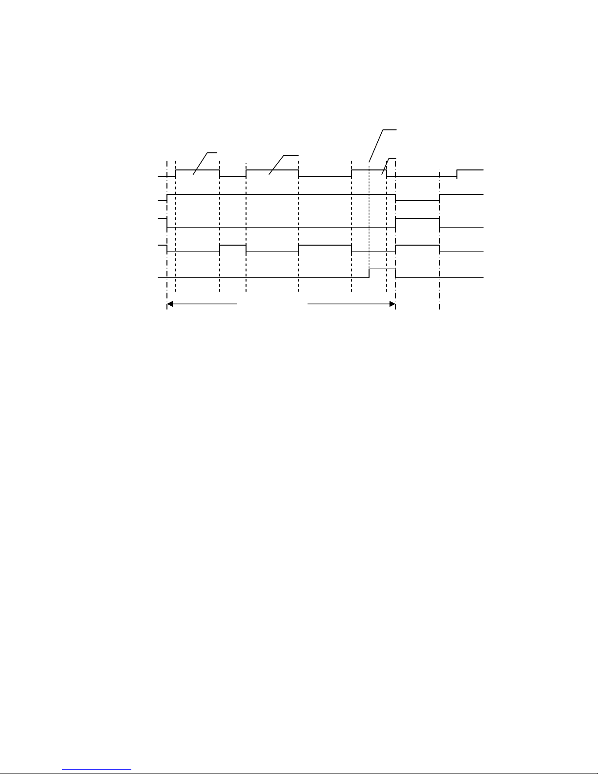
The following is the Micro ADM™ I/O timing diagram:
Weld Arc On
INP2 New Part
CR1 Part Complete
CR2 No
CR3 Fault
Fault
Weld 1
Complete Part
Weld 2
Weld Fault
Weld 3
6.3 SETTING PROCESS CONTROL LIMITS
The Micro ADM™ has a learn mode that is used to establish the Part and weld
process control limits. This mode is used to calculate the required AAD limits
and to establish the base-line weld data limits. The user must first validate the
process parameters and be assured that the parts are conforming to applicable
codes and design specification.
To activate the learn mode assert the INP 1 input. This input is a 24 VDC input
and is an active high input. To activate the learn mode assert and maintain the
INP1 input during the complete learn cycle. Weld 10 parts using the normal
interface sequence. If the optional “INP3 - Part B” input is used, it should be
asserted at the end of Part A welds and cleared when the “INP2-New Part” input
is cleared, after completing the Part B welds.
The Micro ADM™ will assert the “CR2-No Fault” and “CR3-Fault” output will be
cleared to indicate the learn mode. The “CR2-No Fault” output will be cleared
during the arc on period then asserted when the arc is off. After processing 10
parts the Micro ADM™ will assert and hold the “CR2-No Fault” which will indicate
completion of the Learn cycle. The user should than clear the “INP1-Learn” input.
To terminate a learn cycle before completing the 10 parts the user will clear the
“INP1-Learn” Input. The “CR3-Fault” output will be asserted indicating a learn
mode fail.
Warning: Clearing the learn mode prior to completing the 10 welds will result in all
process limits being reset and inhibiting further testing until the part is relearned.
21
Page 26
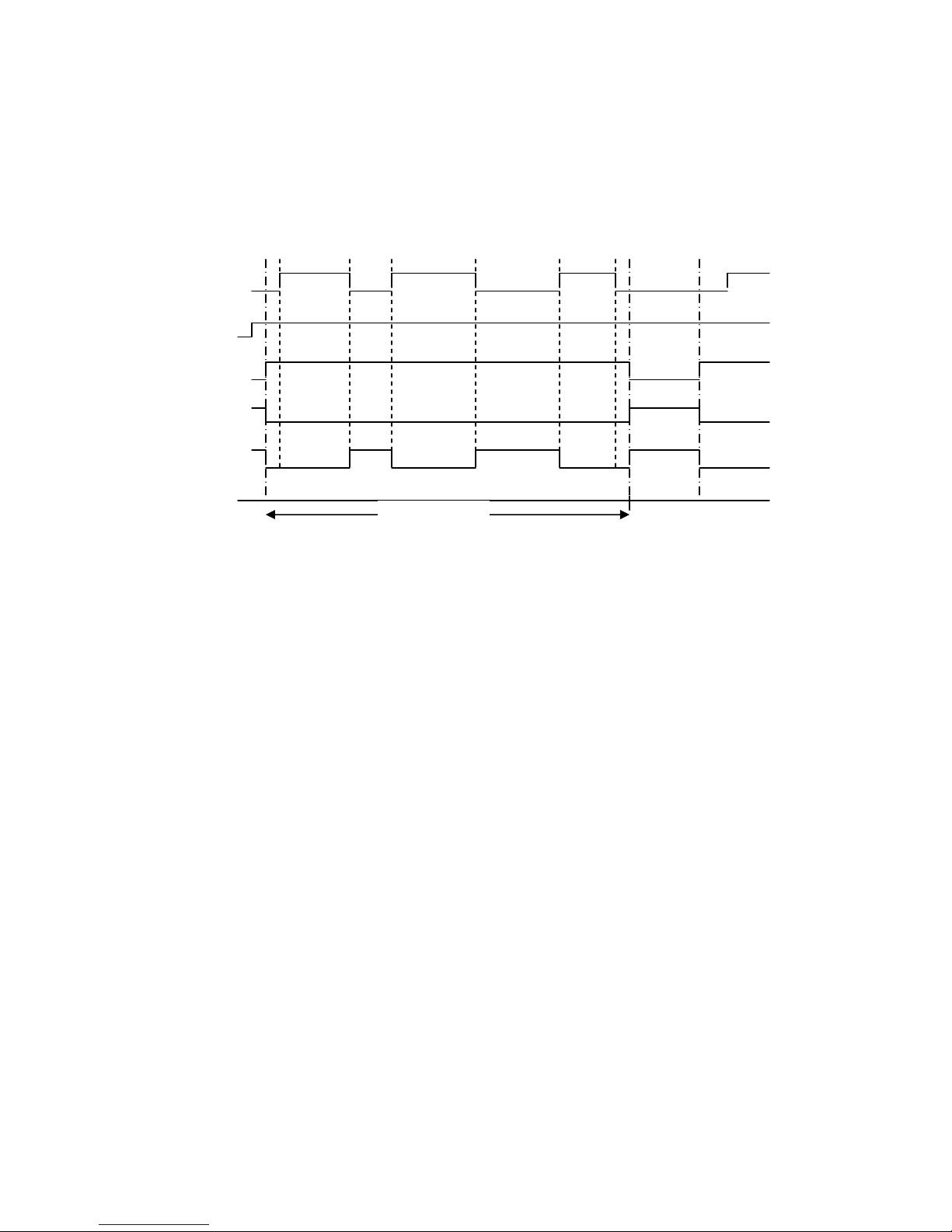
The “CR3-Fault” is reset when a new weld is detected or the “INP1-Learn” input
is asserted. After completing the “Learn” the Micro ADM™ will not begin testing
until the “INP2- New Part” has been cleared then asserted indicating a new part.
The following is the Micro ADM™ Learn Mode I/O timing diagram:
Weld Arc On
INP1 Learn
INP2 New Part
CR1 Part Complete
CR2 No Fault
CR3 Fault
Complete Part
22
Page 27
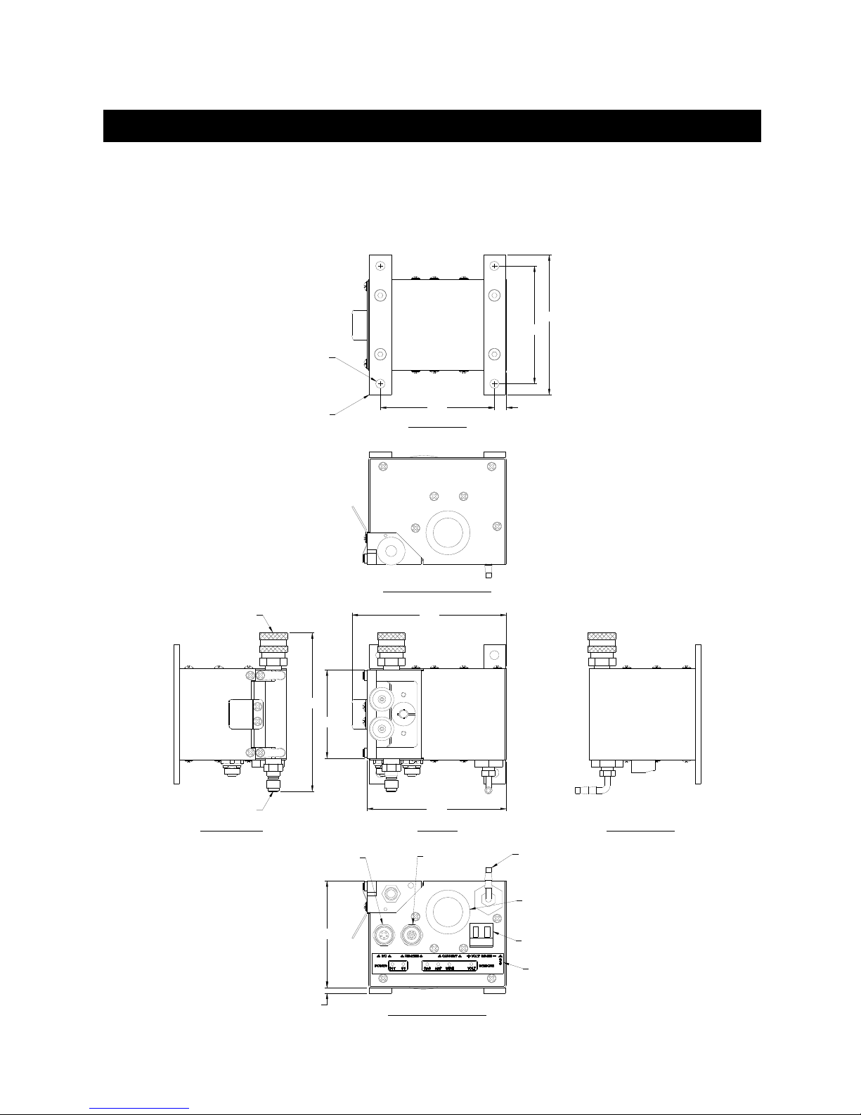
Appendix A Micro ADM™ Installation Specifications
A.1 Micro ADM™ Sensor Mounting Dimensions
4X Ø0.31
4.75
4.00
TWO OPTIONAL
MOUNTING BRACKETS
BOTTOM VIEW
0.403.88
WIRE SPEED
SENSOR FITTING
OUTPUT SIDE PANEL VIEW
5.25
5.38
3.00
WIRE SPEED
SENSOR FITTING
SENSOR COMMUNICATIONS
CONNECTOR
3.62
4.73
TOP VIEW
REMOTE I/O
CONNECTOR
GAS PRESSURE
SENSOR FITTING
CURRENT SENSOR
PASS THROUGH HOLE
VOLTAGE SENSOR
TERMINAL BLOCK
SENSOR STATUS
INDICATORS
RIGHT END VIEWLEFT END VIEW
0.18
INPUT SIDE PANEL VIEW
23
Page 28
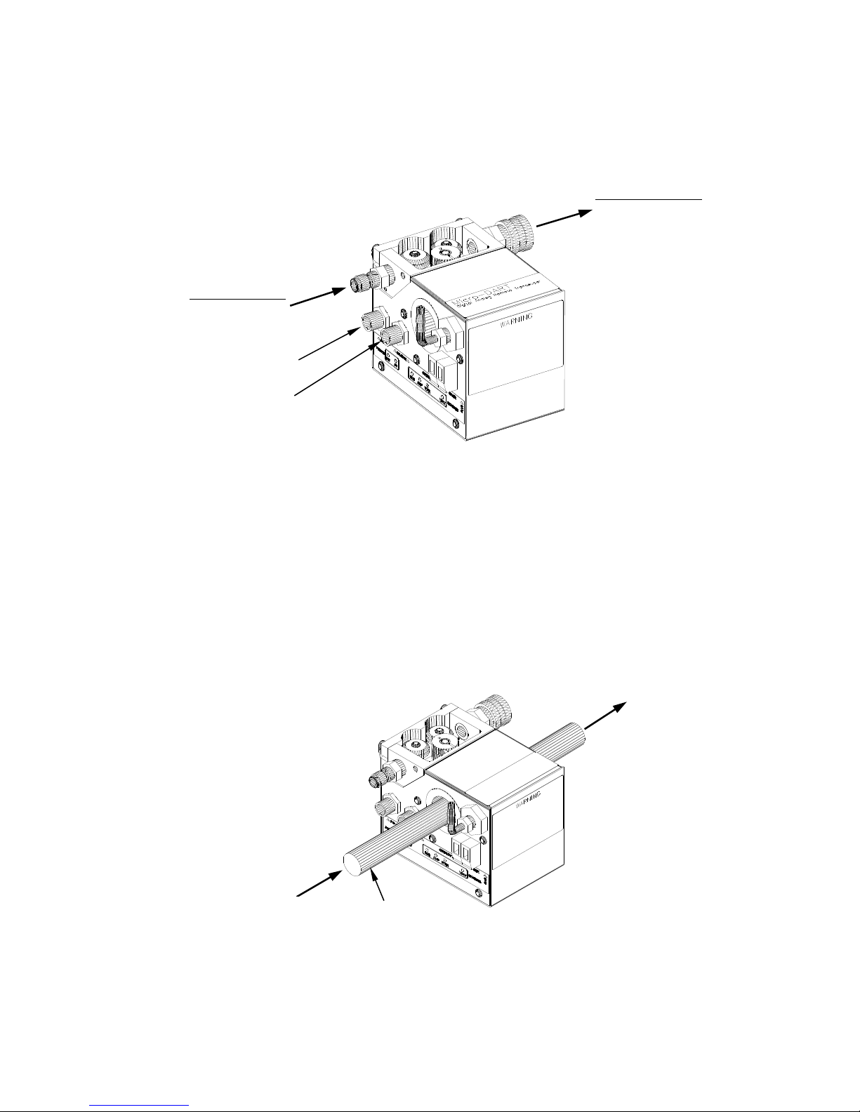
A.2 Sensor Cables and Wire Speed Sensor Installation
From Wire Spool
Wire Inlet Quick
Disconnect Fitting
Communications
Connector
Remote
Connector
A.3 Positive Welding Cable Installation
To Wire Feed Drive
Wire Outlet Quick
Disconnect Fitting
From Welding
Power Source
Positive
Welding Cable
To Wire
Feed Drive
24
Page 29
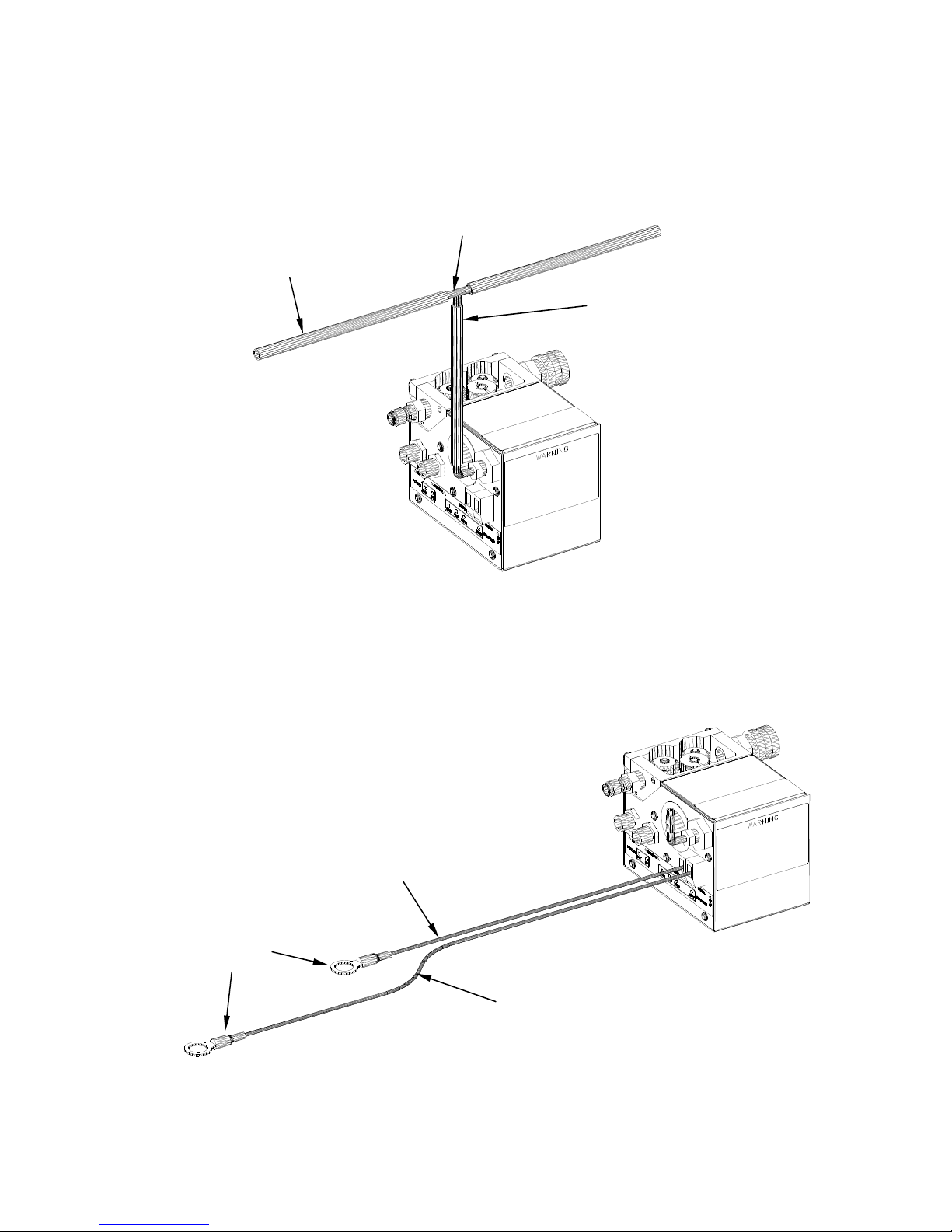
A.4 Gas Pressure Hose Installation
Splice into Customer’s
supplied 1/4” OR
gas hose
3/8” I.D.
CWT Supplied 1/4” or 3/8”
I.D. gas hose barb tee fittings
A.5 Voltage Sensor Installation
CWT supplied
1/4” x 6” long
gas hose
1/2” Ring
Terminals
Route the RED 18 gauge, 600V conductor
(3’ long) from t
the Voltage Sense Terminal Block to the
Positive welding cable connection point at
the Welding Torch or Wire Feeder.
he Positive (+) terminal of
Route the BLACK 18 gauge, 600V conductor
(25’ long) from the Negative (-) terminal of the
Voltage Sense Terminal Block to the Negative
welding cable connection point at the Work
piece ground point.
25
Page 30

A.6 Single Unit Installation
Power Supply
110VAC - P/N: X3T5036
220VAC - P/N: X3T5047
RS-232/RS-485 Converter
P/N: C3A5023
COMMUNICATIONS CABLE INSTALLATION DIAGRAM
RS-232/RS-485 Converter
P/N: C3A5023 – To be
connected to the COM Port on
your Personal Computer
Communications Cable
P/N: A3W0327
(6 meter long)
SYSTEM INSTALLATION DIAGRAM
Communications
RS-485 Terminal
Bloc
k (TB1)
Cable
P/N: A3W0327
Personal
Computer
Micro ADM
P/N: A3A0226
RS-485 CABLE HOOKUP
TERMINAL LABEL WIRE COLOR
1 PWR Brown
2 RD+ N/C
3 RD- N/C
4 TD+ White
5 TD- Blue
6 COM Gray
Note: Cable shield to be clipped off.
26
Page 31
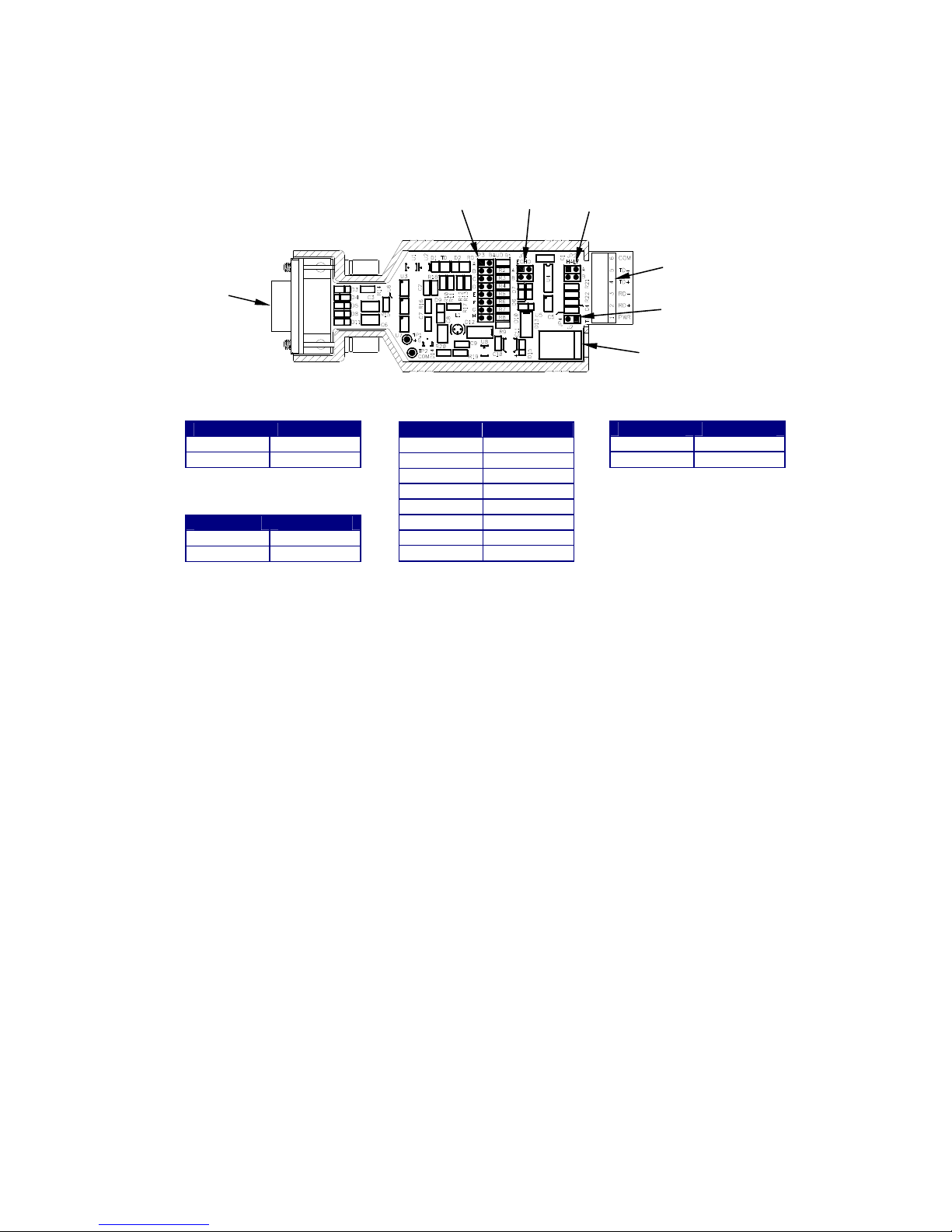
Baud Rate
Jumpers
(JP3)
Echo
Jumpers
(JP1)
Duplex
Jumpers
(JP2)
RS-232
Connector
RS-485 Terminal
Block (TB1)
Internal Power
Jumper (JP4)
Power Supply
Connector
ECHO
JUMPERS (JP1)
ECHO JUMPER
On A
Off** B
** Denotes the default jumper
DUPLEX JUMPERS (JP2)
DUPLEX JUMPER
Full None
Half** A and B
** Denotes the default jumper
B
AUD RATE JUMPERS (JP3)
BAUD JUMPER
1200 A
2400 B
4800 C
9600 D
19200** E
38400 F
57600 G
115200 H
** Denotes the default jumper
PO
WER JUMPERS (JP4)
POWER
External** Yes
Internal No
** Denotes the default jumper
JUMPER
RS-485/RS-232 CONVERTER JUMPER LOCATIO N DIAGRAM
27
Page 32
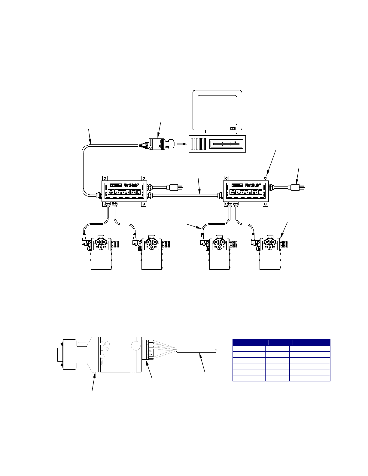
A.7 Multiple Unit Network Installation
Personal
RS-485 Cable
P/N: X3W5042
(Order b
y the Foot)
RS-232/RS-485
Converter
P/N: C3A5023
Computer
RS-485 Cable
P/N: X3W5042
y the Foot)
(Order b
Communications Cable
P/N: A3W0327
(6 meters long)
SYSTEM INSTALLATION DIAGRAM
RS-485 Cable
P/N: X3W5042
y the foot)
(order b
RS-232/RS-485 Converter
P/N: C3A5023
COMMUNICATIONS CABLE INSTALLATION DIAGRAM
RS-485 Terminal
k (TB1)
Bloc
NetHub Assembly
110VAC - P/N: A3A0214
220VAC - P/N: A3A0219
Power Cable
Micro ADM
P/N: A3A0226
RS-485 CABLE HOOKUP
TERMINAL LABEL WIRE COLOR
1 PWR Orange
2 RD+ N/C
3 RD- N/C
4 TD+
5 TD- White/Blue
6 COM White/Orange
Note: Cable shield to be clipped off.
Blue
28
Page 33
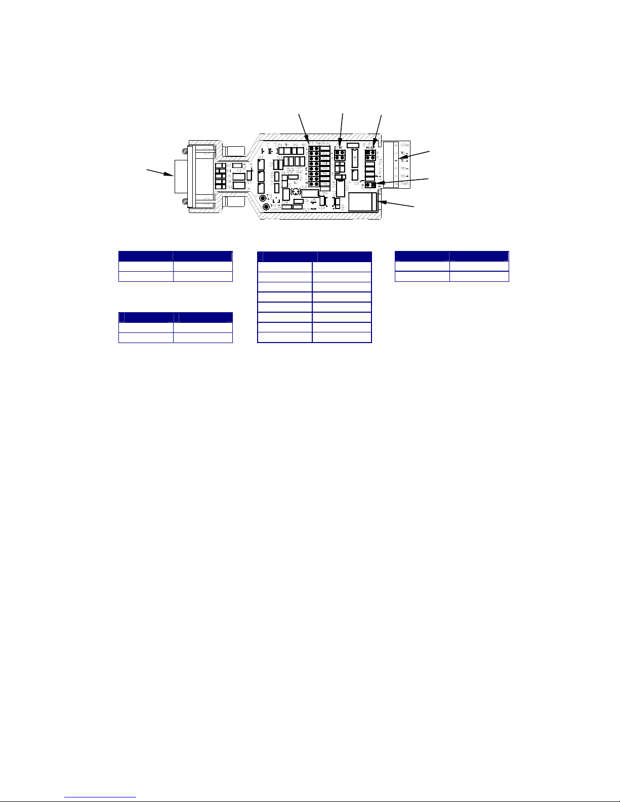
RS-232
Connector
ECHO JUMPERS (JP1)
ECHO
On** A
Off B
** Denotes the default jumper
DUPLEX JUMPERS (JP2)
DUPLEX JUMPER
Full** None
Half A and B
** Denotes the default jumper
RS-485/RS-232 CONVERTER JUMPER LOCATIO N DIAGRAM
JUMPER
Baud Rate
Jumpers
(JP3)
BAUD RATE JUMPERS (JP3)
BAUD JUMPER
1200 A
2400 B
4800 C
9600 D
19200** E
38400 F
57600 G
115200 H
** Denotes the default jumper
Echo
Jumpers
(JP1)
Duplex
Jumpers
(JP2)
RS-485 Terminal
Internal Pow
Power Supply
Connector
POWER JUMPERS (JP4)
POWER JUMPER
External** Yes
Internal No
** Denotes the default jumper
Bloc
k (TB1)
Jumper (JP4)
er
29
Page 34
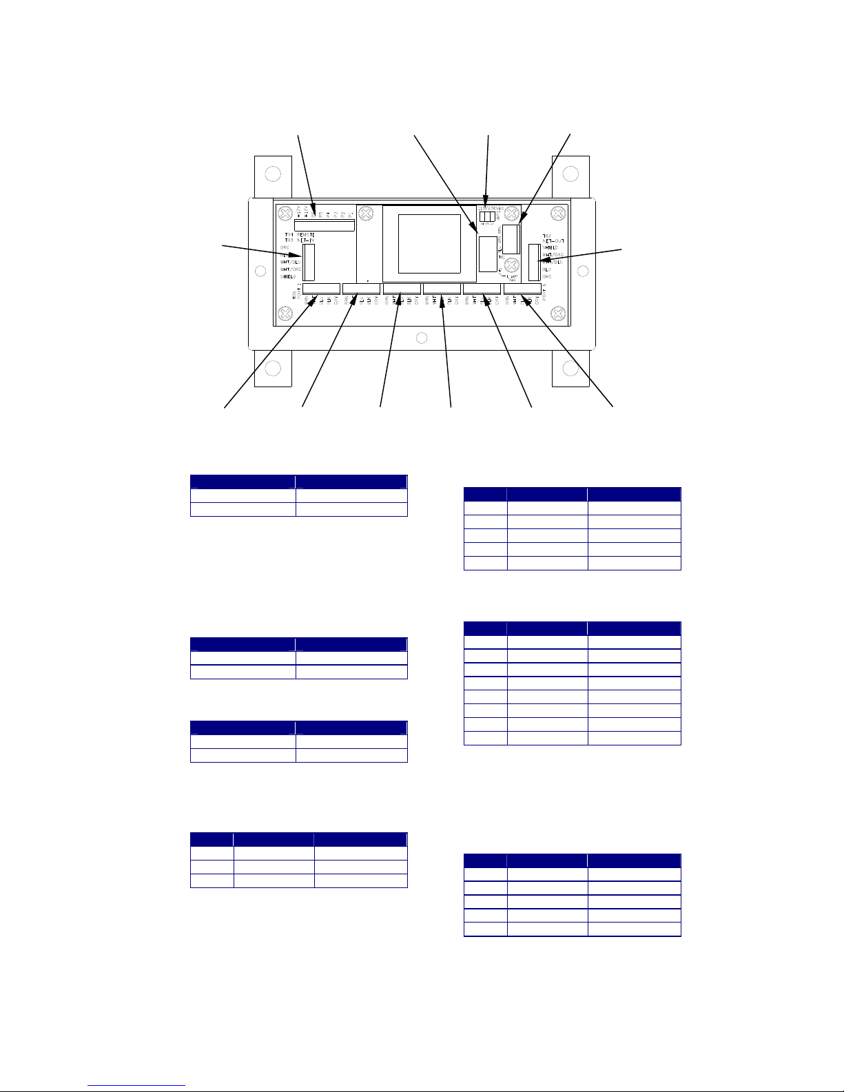
-
Terminal Block
Remote I/O
TB4
Fuse F1
1 Amp
JMP1
Jumper
110/220 AC
Terminal Block
TB1 - AC Power
Terminal Block
TB3 - Net In
Terminal Block
TB2 - Net Out
Terminal Block
TB5 - Port 1
Terminal Block
TB6 - Port 2
Terminal Block Terminal Block Terminal Block
TB7 - Port 3 TB8 - Port 4 TB10 - Port 6
Terminal Block
TB9 - Port 5
JUMPER JMP1 - 110/220VAC
VOLTAGE JUMPERS
110VAC A and B
220VAC C
The next two jumpers (JP1 and JP2) are for
whether the RS-485 Converter is powered
from an external power source or uses the
power supplied by the NetHub.
JUMPER JP1 - NPWR
POWER JUMPERS
External Powered A
NetHub Powered A and B
JUMPER JP2 - NCOM
POWER JUMPERS
External Powered A
NetHub Powered A and B
TERMINAL BLOCK TB1 – AC POWER
PIN REFERENCE WIRE COLOR
1 HOT BLU
2 EARTH GRN/YEL
3 NEU BRN
NetHub JUMPER and TERMINAL BLO CK LOCATION DIAGRAM
TERMINAL BLOCK TB2 – NET OUT
TERMINAL BLOCK TB3 – NET IN
PIN REFERENCE WIRE COLOR
1 NET PWR ORG
2 NET+ BLU
3 NET- WHT/BLU
4 NET COM WHT/ORG
5 EARTH GND SHIELD
Note: Cable shield to be clipped off.
TERMINAL BLOCK TB4 – REMOTE
PIN REFERENCE WIRE COLOR
1 RMT P1 WHT
2 RMT P2 BRN
3 RMT P3 GRN
4 RMT P4 YEL
5 RMT P5 GRY
6 RMT P6 PNK
7 +12 VDC BLU
8 +12VDC RED
TERMINAL BLOCK TB5 – PORT 1
TERMINAL BLOCK TB6 – PORT 2
TERMINAL BLOCK TB7 – PORT 3
TERMINAL BLOCK TB8 – PORT 4
TERMINAL BLOCK TB9 – PORT 5
TERMINAL BLOCK TB10 – PORT 6
PIN REFERENCE WIRE COLOR
1 +12V BRN
2 NET+ WHT
3 NET- BLU
4 REMOTE ON BLK
5 GND GRY
Note: Cable shield to be clipped off.
30
Page 35
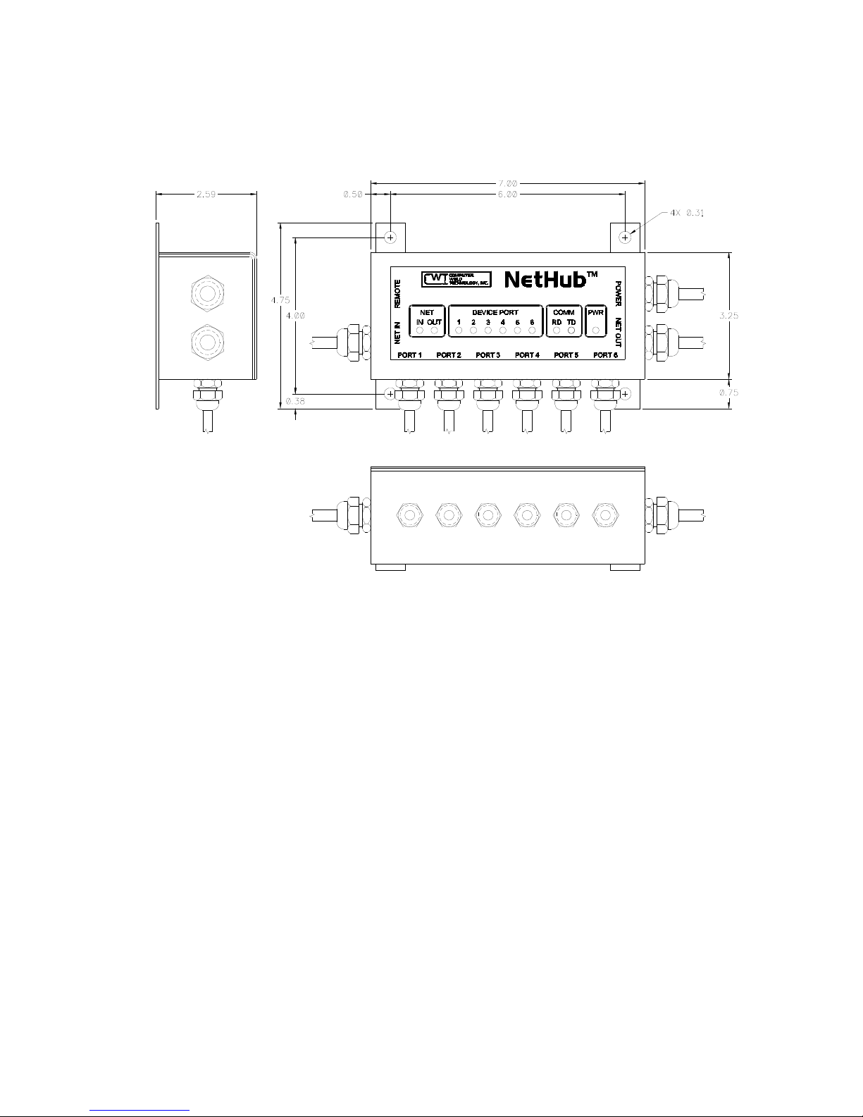
A.8 NetHub Mounting Dimensions
31
Page 36
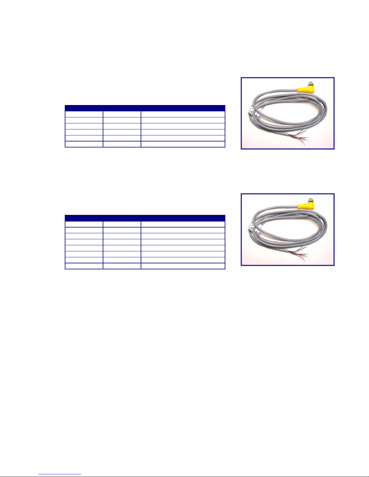
A.9 Communications Cable P/N: A3W0327
This part includes both a cable and a strai n relief.
The strain relief is to be used for a NetHub install ation.
WIRE COLOR FROM REFERENCE
BROWN ITEM 1 PIN 1 +24 VDC
WHITE ITEM 1 PIN 2 NET+
BLUE ITEM 1 PIN 3 NET-
BLACK ITEM 1 PIN 4 PSEL
GRAY ITEM 1 PIN 5 24VDC GROUND
SHIELD CABLE SHIELD
A.10 Remote I/O Cable P/N: X3W5102
WIRE COLOR FROM REFERENCE
WHITE ITEM 1 PIN 1 Part Complete (CR1)
BROWN ITEM 1 PIN 2 +24 VDC
GREEN ITEM 1 PIN 3 No Fault (CR2)
YELLOW ITEM 1 PIN 4 Fault (CR3)
GRAY ITEM 1 PIN 5 COM
PINK ITEM 1 PIN 6 Learn (INP1)
BLUE ITEM 1 PIN 7 Part (INP2)
RED ITEM 1 PIN 8 Part B (NP3)
WIRE LIST
6-Meter Long Cable
WIRE LIST
6-Meter Long Cable
32
Page 37
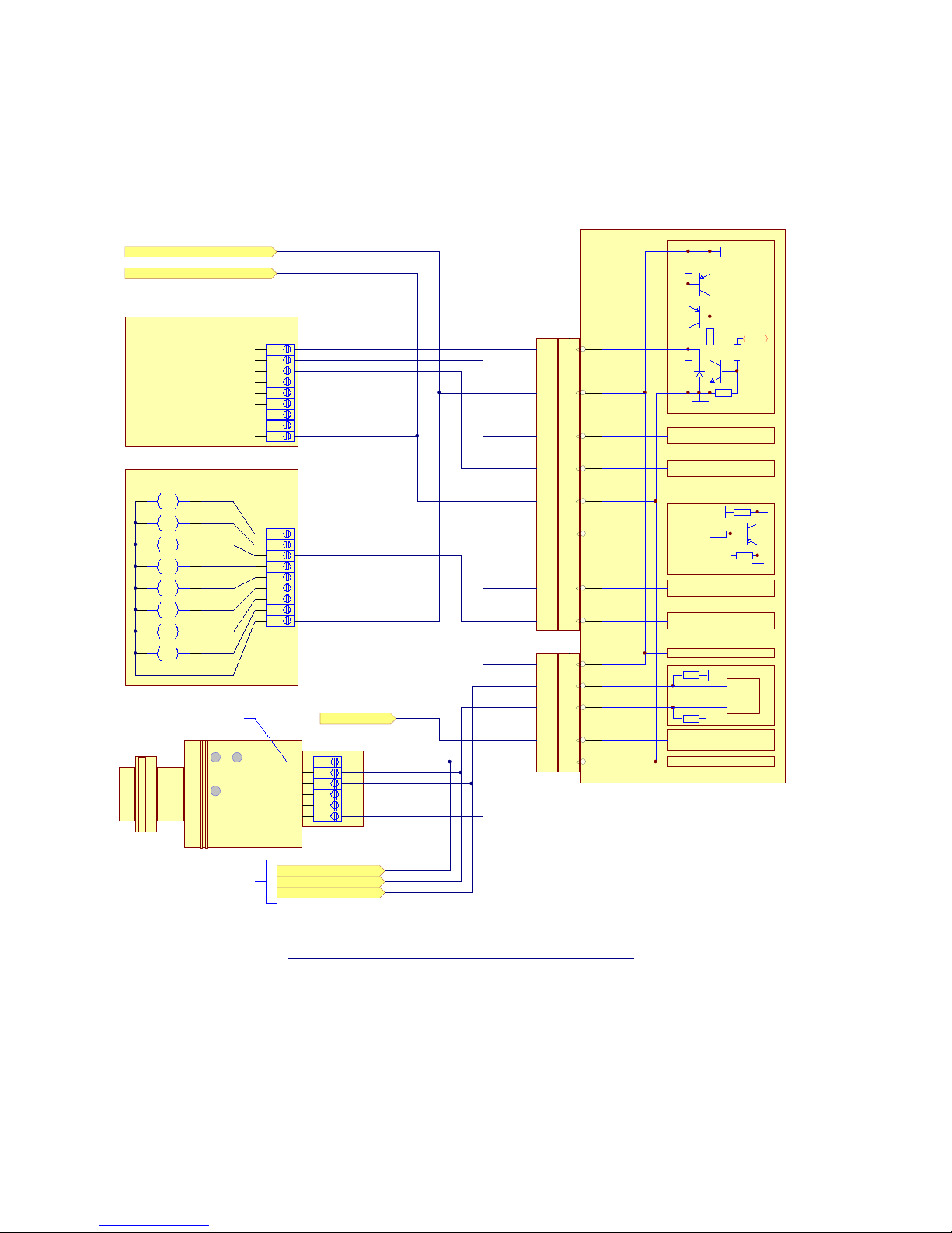
A.11 Typical External Powered PLC I/O System Integration
MICRO ADM SE NS O R I/O
USER SUPPLIED +24 VDC
USER SUPPLIED 24 VDC COM
PL
C 24 VDC INP UT MODULE
"PASS"
"FAIL"
I:1/0
I:1/1
I:1/2
I:1/3
I:1/4
I:1/5
I:1/6
I:1/7
COM
"PART COMPLETE"
PLC 24 VDC OUTP UT MODULE
LEARN
O:1/0
PART
O:1/1
GROUP
O:1/2
SPARE 1
O:1/3
SPARE 2
O:1/4
SPARE 3
O:1/5
SPARE 4
O:1/6
SPARE 5
O:1/7
RS232/RS485 CONVERTER
P/N C3A5023
CONVERTER JUMPERS:
J1=B
J2=A & B
TO ADDITIONAL SENSORS
P1 - I/O COMM
1:1
1
2
3
4
5
6
7
8
9
0:1
1
2
3
4
5
6
7
8
9
JP3=E
JP4=ON
TO SENSOR COM
TO SENS OR NETTO SENS OR NET+
WHT
GRN
YEL
GREY
PINK
BLU
RED
BRN
+24
CR1- READY
TYPICAL
OUTPUT
24 V @ 100 MA
P2 - REMOTE
WHT
BRN
GRN
YEL
GREY
PINK
BLU
RED
BRN
WHT
PSEL
COM
6
TD-
5
TD+
4
RD-
3
RD+
2
PWR
1
BLK
GRY
BLU
T
WH
BRN
GRY
BLU
WHT 4. RS-485 CONVERTER MAY BE REPLACED WITH OPTIONAL NETHUB PROVIDING
BLU
BLK
GRY
NOTES:
1. POWER PROVIDED TO RS-485 CONVERTER FROM SENSOR
2. SENSOR OUTPUT LEVELS ARE SET BY USER SUPPLIED POWER SUPPLY
3. FOR MULTIPLE SENSORS CONNECTED TO PLC I/O USE COMMON POWER
SUPPLY FOR ALL SENSORS CONNECTED TO PLC I/O MODULE.
POWER AND COMMUNICATIONS FOR 6 SENSORS.
READY
1
1
+24
2
2
COM
PASS
3
3
FAIL
4
4
COM
5
5
LEARN
6
6
PART
7
7
GROUP
8
8
P1 - I/ O
+24
1
1
NET+
2
2
NET-
3
3
RMT ON
4
4
COM
5
5
CR2 - PASS OUTPUT
CR3 - FAIL OUTPUT
INP1 - LEARN INP UT
TYPICAL INPUT
10-24 VDC @ 0.25 W
INP2 - NEW PART INPUT
INP3 - GROUP B INPUT
SENSOR & I/O PWR +24 VDC
680
680
INP4 - REMOTE ON INPUT
SENSOR & I/O PWR COMMON
+5
+5
COM
RS-485
DRIVER
CR1
COM
TYPICAL SENSOR POWERED PLC TO MICRO ADM INTERFACE
33
Page 38
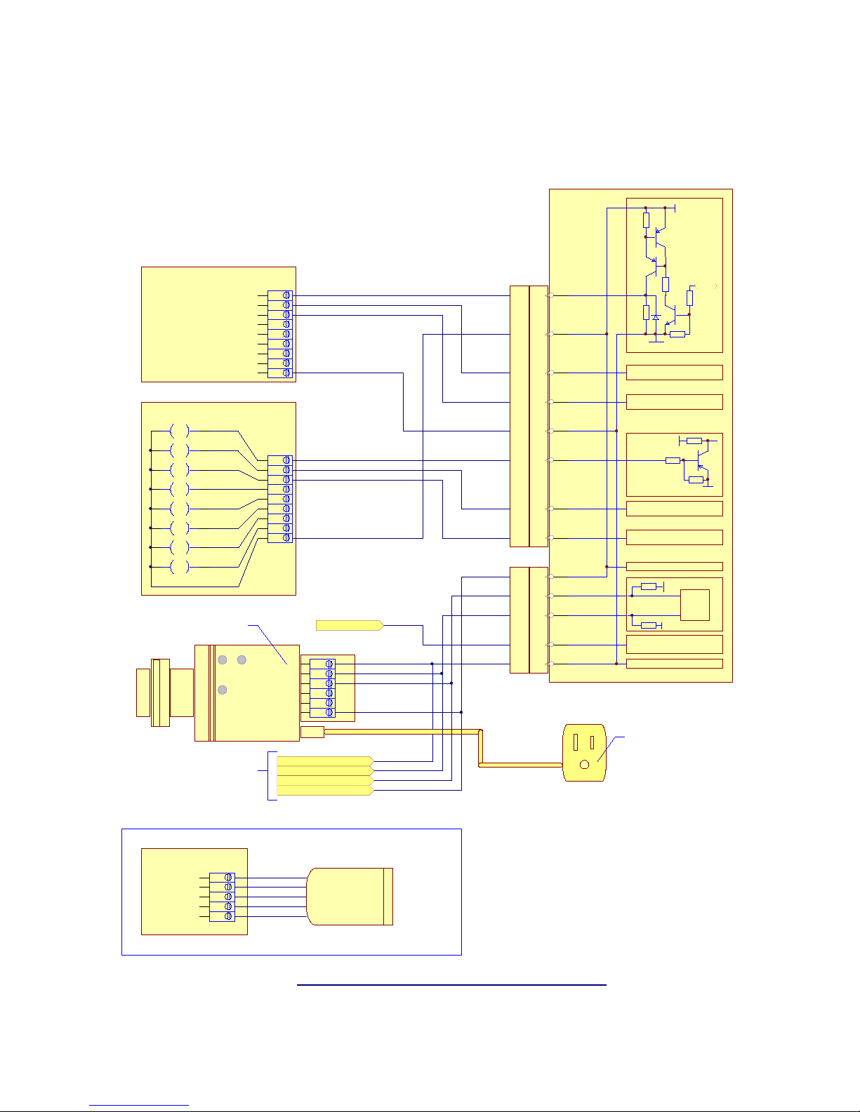
A.12 Typical Sensor Powered PLC I/O System Integration
MICRO ADM SE NSO R I/O
PL
C 24 VDC INPUT MODULE
"PART COMPLETE"
"PASS "
"FAIL"
PLC 24 VDC OUTPUT MODULE
LEARN
O:1/0
PART
O:1/1
GROUP
O:1/2
SPARE 1
O:1/3
SPARE 2
O:1/4
SPARE 3
O:1/5
SPARE 4
O:1/6
SPARE 5
O:1/7
RS232 /RS485 CONV ERTER P/N C3A5023
CONVERTER JUMPERS:
J1=B
J2=A & B
TO ADDITIONAL SENSORS P1 - I/O COMM
OPTIONAL NETHUB CONNECTION
NETHUB PORT(1-6)
+12 V D C
NET+
NET-
RMT ON
COM
TB5 - TB10
1
2
3
4
5
I:1/0
I:1/1
I:1/2
I:1/3
I:1/4
I:1/5
I:1/6
I:1/7
COM
BRN
WHT
BLU
BLK
GRY
1:1
1
2
3
4
5
6
7
8
9
0:1
1
2
3
4
5
6
7
8
9
JP3=E
JP4=ON
TO SENSOR COM
TO SENSOR NETTO SENSOR NET+
TO SENSOR +24
WHT
GRN
YEL
GREY
PINK
BLU
RED
BRN
PSEL
COM
6
TD-
5
TD+
4
RD-
3
RD+
2
PWR
1
SENSOR COMM
CABLE P/N A3W0327
GRY
BLU
WH
BRN
BLK
T
GRY
BLU
WHT
BRN
TO S E N S OR
I/O COMM PORT
WHT
BRN
GRN
YEL
GREY
PINK
BLU
RED
BRN
WHT
BLU
BLK
GRY
NOTES:
1. POWER PROV ID ED TO RS-485 CONVERTER FROM SENSOR
2. SENSOR OUTPUT LEVELS ARE SET BY USER SUPPLIED POWER SUPPLY
3. UP TO 4 SENSORS MAY BE CONNECTED TO SINGLE RS-485 CONVERTER
4. RS-485 CONVERTER MAY BE RE PLACED WITH OPTIONAL NETHUB PROVIDING
POWER AND COMMUNICATIONS FOR 6 SE NSORS.
1
2
3
4
5
6
7
8
1
2
3
4
5
P2 - REMOTE
READY
1
+24
2
PASS
3
FAIL
4
COM
5
LEARN
6
PART
7
GROUP
8
P1 - I/O
+24
1
NET+
2
NET-
3
RMT ON
4
COM
5
+24
CR1- READY
TY P I C AL
OUTPUT
24 V @ 100 MA
CR1
COM
CR2 - PASS OUTPUT
CR3 - FAIL OUTPUT
+5
INP1 - LEARN INPUT
TYPICAL INPUT
10-24 VDC @ 0.25 W
INP2 - NEW PART INPUT
INP 3 - GR OUP B INP U T
SENSOR & I/O PWR +24 VDC
680
680
INP4 - REMOTE ON INPUT
SENSOR & I/O PWR COMMON
115 VA C WALL CHARGER
P/N C3A5023
+5
COM
RS-485
DRIVER
COM
TYPICAL SENSOR POWERED PLC TO MICRO ADM INTERFACE
34
Page 39
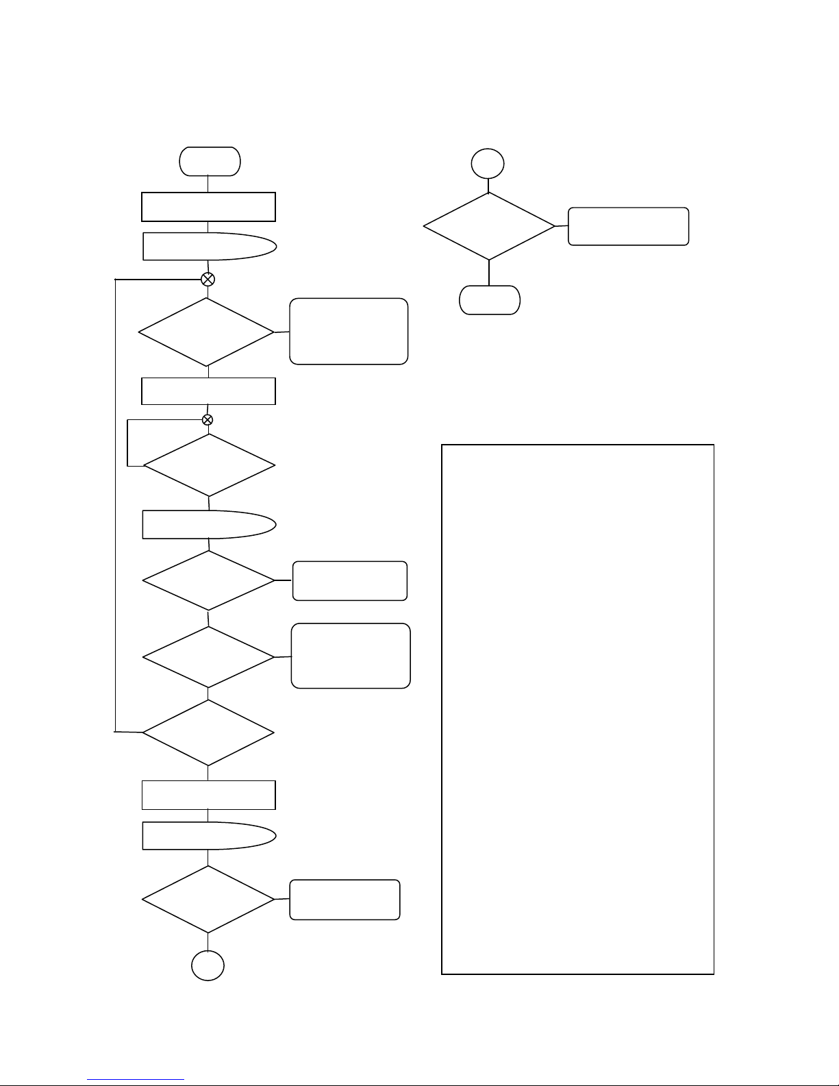
A.13 Normal Weld Cycle Process Control Flow Chart
”
”
START
SET “PART” O:1/1
DELAY 80 MSEC
“NEW PART”
LOW
START WELD E VENT
WELD
COMPLETE
DELAY 150 MS EC
“FAIL”
LOW
“PASS”
HIGH
PART
COMPLETE
RESET “PART” O:1/1
DELAY 80 MSEC
“FAIL”
LOW
1
CLEAR “PART
O:1/1
SENSOR ERROR
“SENSOR
PART FAIL ERROR
OFF-LINE”
WELD FAIL ERROR
“WELD FAULT”
CLEAR “PART
O:1/1
SENSOR ERROR
“
“PART FAULT”
1
“PASS”
HIGH
SENSOR ERROR
“SENSOR FAULT”
END
OPERATIONAL SEQUENCE:
32. Set Micro ADM sensor “PART” input Bit O:1/1.
33. Delay 80 msec for sensor I/O debounce time.
34. Test the sensor “NEW PART” output I:1/0 for low
level indicating new part active. If High then clear
the sensor “PART” input Bit O:1/1. Then handle
sensor “Off-Line” error.
35. Start fixture weld cycle.
36. Wait for weld cycle complete.
37. Delay for 150 msec to allow sensor validation of
weld arc off.
38. Test the sensor “Fail” output I:1/2 if set handle
Weld Fault error condition.
39. Test the sensor “Pass” Output I:1/1 to validate
proper sensor operation. Only one output “Fail”
“Pass” will be set if neither output is set handle
”
sensor fault error.
40. Test for last weld on part. If not last weld then
continue steps 1 – 9 until all welds are completed
before validating the sensor’s Part “Pass” or “Fai
output.
41. Reset the sensor “Part” input O:1/1
42. Delay for 80 msec for I/O sensor debounce time
43. Test the sensor “New Part” output I:1/0 to validate
part complete. If set handle sensor fault error.
44. Test the sensor part “Fail” output I:1/2 if set
handle Part Fault error condition.
45. Test the sensor part “Pass” Output I:1/1 to
validate proper sensor operation. Only one output
“Fail” or “Pass” will be set if neither output is set
handle sensor fault error.
Note: If the arc is active the sensor
“Pass” output will be low. Verify Arc
condition in error handler before sett
sensor fault error.
Note: The actual Input/Output bits
assigned to the Micro ADM sensor w
depend on actual system integration to
PLC controller.
or
off
ing
ill
l”
.
35
Page 40
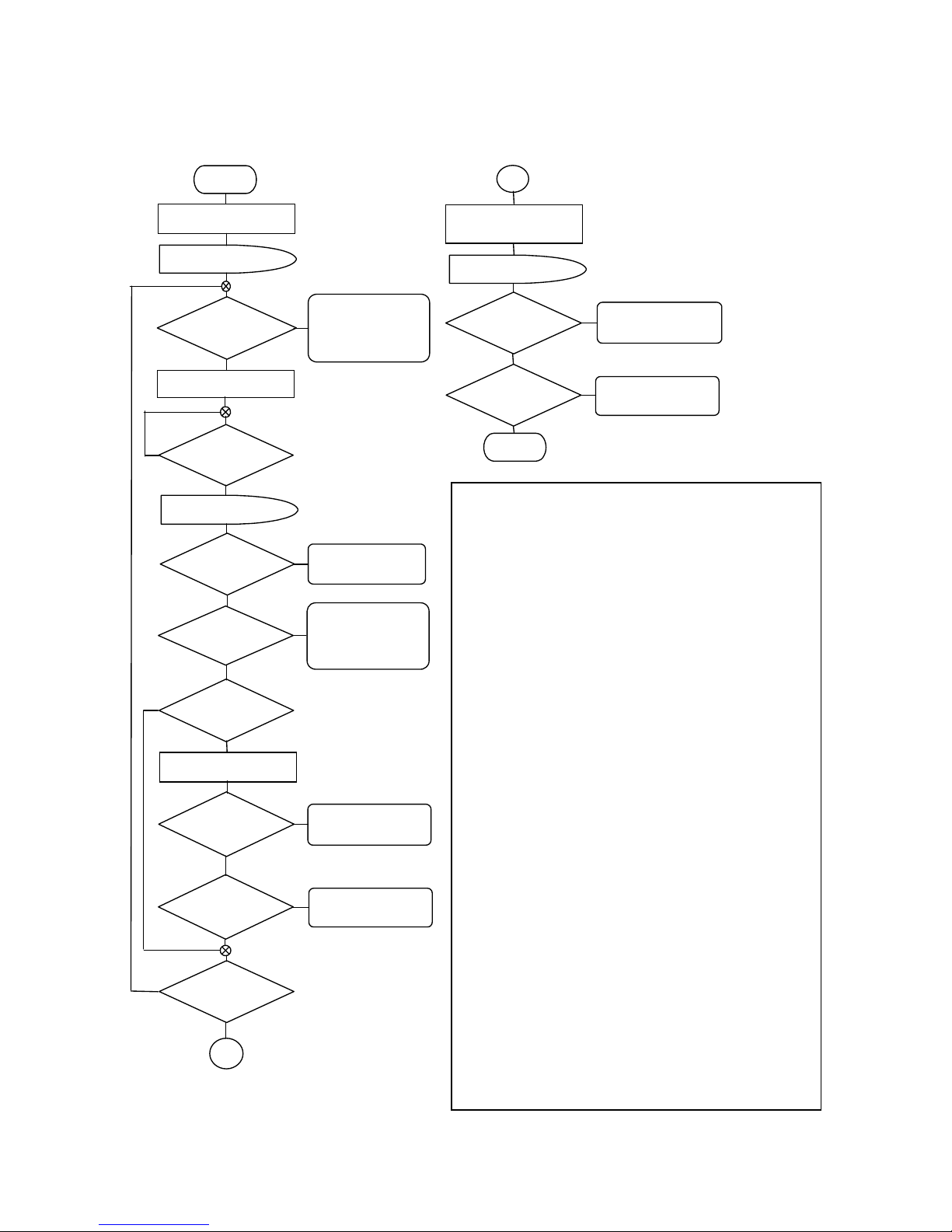
A.14 Group Weld Cycle Process Control Flow Chart
”
F
-
”
”
START
SET “PART” O:1/1
DELAY 80 MSEC
“NEW PART”
LOW
START WELD EVENT
WELD
COMPLETE
DELAY 150 MSEC
“FAIL”
LOW
“PASS”
GROUP A
COMPLETE
SET “GROUP” O:1/2
“FAIL”
LOW
“PASS”
HIGH
PART
COMPLETE
1
CLEAR “PART
O:1/1
SENSOR ERROR
“SENSOR OF
WELD FAIL ERROR
“WELD FAULT”
CLEAR “PART
SENSOR ERROR
“
PART A FAIL ERROR
“GROUP A FAULT”
SENSOR ER R OR
“SENSOR FAULT”
LINE”
O:1/1
RESET “PART” O:1/1 &
“GROUP
O:1/2
DELAY 80 MSEC
“FAIL”
LOW
PART B FAIL ERROR
“PART B FAULT”
“PASS”
LOW
END
GROUP A/B OPERATIONAL SEQUENCE
14. Set the sensor “PART” input Bit O:1/1.
15. Delay 80 msec for sensor I/O debounce time.
16. Test the sensor “NEW PART” output I:1/0 for
indicating new part active. If High then clear the
“PART” input Bit O:1/1. Then handle sensor “Off-Line
17. Start fixture weld cycle
18. Wait for weld cycle complete.
19. Delay for 150 msec to allow sensor validat
20. Test the sensor “Fail” output I:1/2. If set handle
”
error condition.
21. Test the sensor “Pass” Output I:1/1
operation. Only one output “Fail” or “Pass” w
output is set handle sensor fault error.
22. Test for last weld on Group A Part. If not last w
go to step 13.
23. Set the sensor “Group” input O:1/2. When set the
perform Group A validation test.
24. Test the sensor Group A “Fail” output I:1/2. If
Group A part Fault error condition.
25. Test the sensor part “Pass” Output I:1/1
sensor operation. Only one output “Fail” or “Pas
neither output is set handle sensor fault error.
26. Test for last weld on part. If not last we
until all welds are completed before validating
B part “Pass” or “Fail” output.
27. Reset the sensor “Part” input O:1/1 and “Group
28. Delay for 80 msec for I/O sensor debounce time
29. Test the sensor “New Part” output I:1/0 to va
complete. If set handle sensor fault error.
30. Test the sensor Group B “Fail” output I:1/2. If
Group B Fault error condition.
31. Test the sensor part “Pass” Output I:1/1
sensor operation. Only one output
neither output
Note: The actual Input/Output bits assigned to the Micro ADM
sensor will depend on actual system integration to PLC
controller.
Note: If the arc is active the sensor “
will be low. Verify Arc off condition in
before setting sensor fault error.
is set handle sensor fault error.
SENSOR ERROR
“SENSOR FAULT”
to validate proper sensor
“Fail” or “Pas
:
low level
sensor
” error.
ion of weld arc off.
Weld Fault
ill be set if neither
Pass” output
error handler
eld on Group A
sensor will
set handle the
to validate proper
ld continue steps 1 – 9
to validate proper
s” will be set if
sensor’s Group
” input O:1/2.
.
lidate part
set handle
s” will be set if
36
Page 41
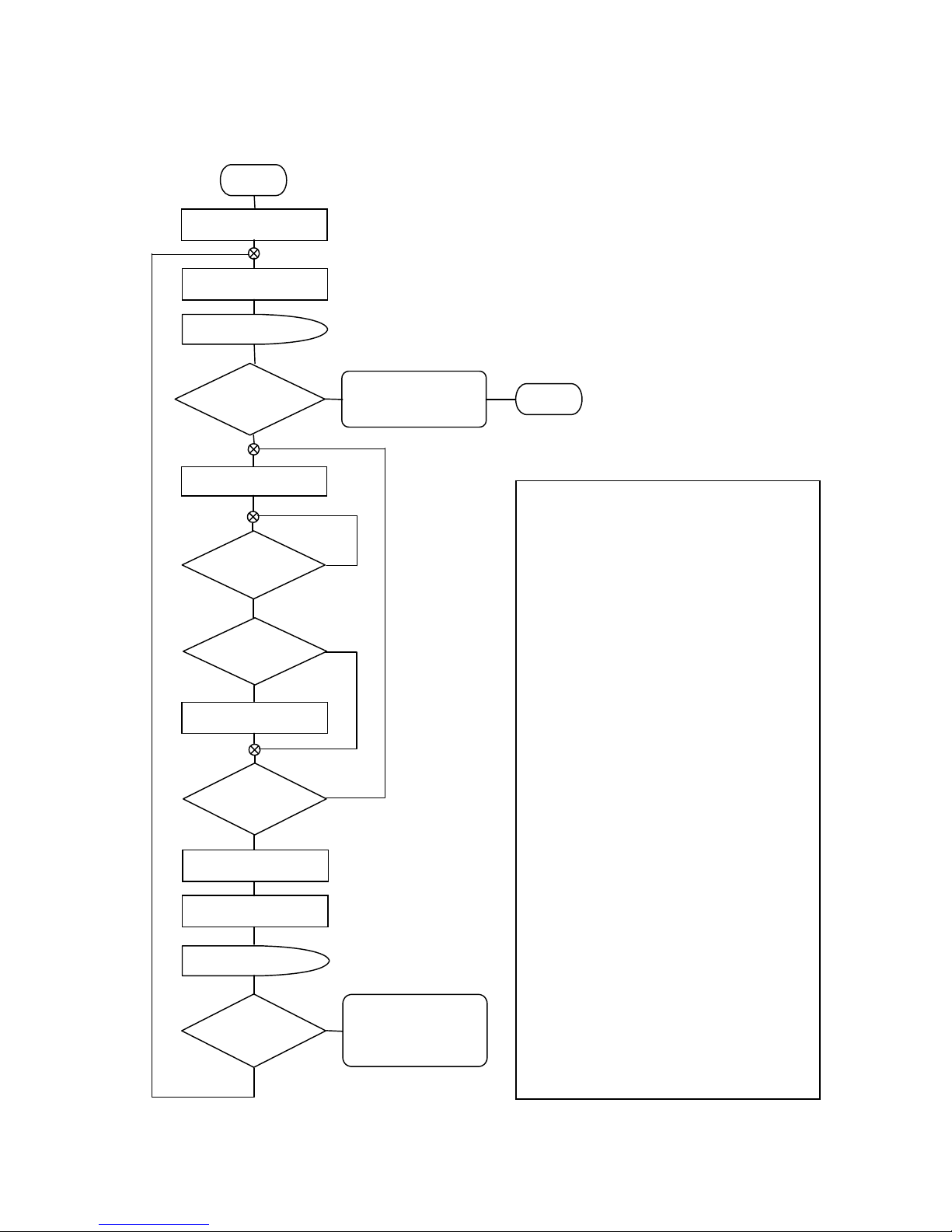
A.15 Learn Weld Cycle Process Control Flow Chart
”
”
START
SET “Learn” O:1/0
SET “PART” O:1/1
DELAY 80 MSEC
“NEW PART”
LOW
START WELD EVENT
WELD
COMPLETE
GROUP A
COMPLETE
SET “GROUP” O:1/2
PART
COMPLETE
RESET “GROUP” O:1/2
RESET “PART” O:1/1
DELAY 80 MSEC
“FAIL”
Low
CLEAR “PART” O:1/1 &
“LEARN” O:1/0
LEARN COMPLETE
CLEAR “LEARN
HANDLE
MODE FAULT
“LEARN MODE FA ULT
O:1/0
“LEARN”
END
LEAR
Set the “Learn” input O:1/0.
1.
Set the sen
2.
3. Delay
4.
Test the sensor “NEW PART” output I:1/0 for low
level ind
the sensor “
input B
error.
5.
Start fixture weld cycle.
6. Wait for w
7. Delay
we
8.
If the application requires Group A and Group B
part testing
If True then set the sensor “Group” input O:1/2
to sign
of Group B welds.
9. Test for la
we
completed before clearing the sensor Part input
O:1/1.
Reset the sensor “Part” input O:1/1 and the
10.
sensor
11. Delay
Test the sensor Part “Fail” output I:1/2. If set
12.
handle Learn Fault error condition. This fault
indicates an
part.
Repeat Steps 2-13 until the sensor “New Part”
13.
output
input
mode.
Note: The actua
Micro ADM
integration to
N MODE OPERATIONAL SEQUENCE:
Warning: When “Learn input is set the
Micro ADM will clear all previous limits.
sor “PART” input Bit O:1/1.
80 msec for sensor I/O debounce time.
icating new part active. If High then clear
PART” input Bit O:1/1 and “Learn”
it O:1/0. Then handle sensor “Off-Line”
eld cycle complete.
for 150 msec to allow sensor validation of
ld arc off.
. Then test for end of Group A welds.
ify the end of Group A welds and the start
st weld on part. If this is not the last
ld continue steps 1 – 9 until all welds are
Note: The learn mode requires ten (10)
parts to establish the process limits.
“Group” input O:1/2.
for 80 msec for sensor I/O debounce time.
invalid weld count during the last
I:1/0 is not cleared when the sensor “Part”
O:1/1 is set. This indicates end of learn
l Input/Output bits assigned to the
sensor will depend on actual system
PLC controller.
37
Page 42
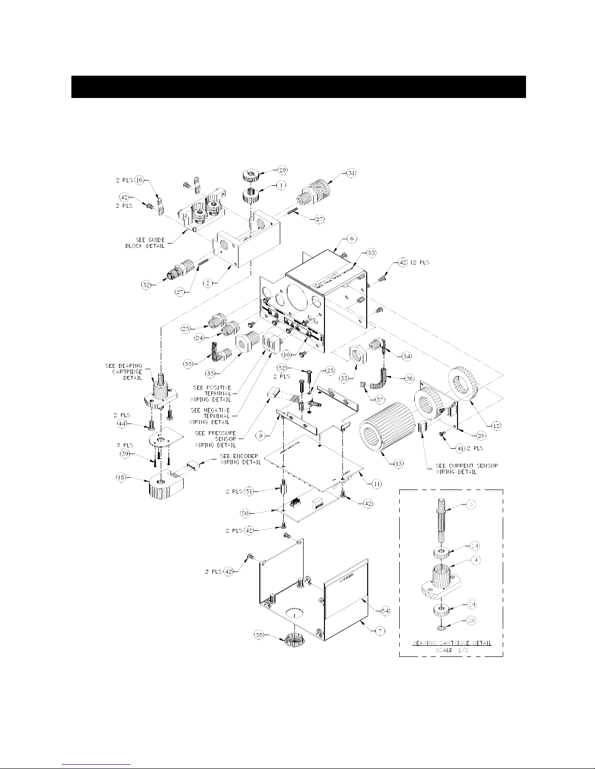
Appendix B Micro ADM™ Assembly Parts List
B.1 Micro ADM™ Sensor Assembly P/N: A3A0226 Rev: 0
38
Page 43
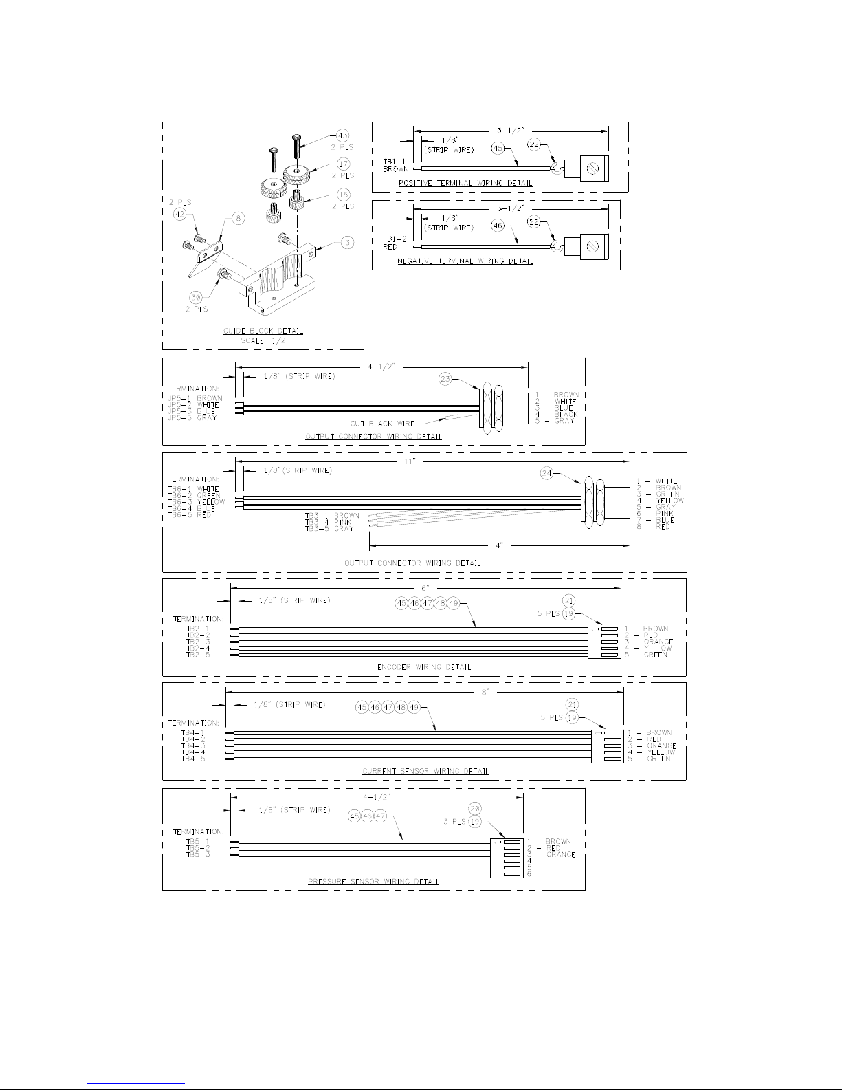
39
Page 44

PARTS LIST
ITEM QTY PART NUMBER DESCRIPTION
1 1 A2A0014 Driven Wheel
2 1 A2M0206 Transducer Block
3 1 A2M0203 Guide Block
4 1 A2M0204 Bearing Cartridge
5 1 A2M0205 WFS Shaft
6 1 A3E0159 Top Cover
7 1 A3E0160 Bottom Cover
8 1 A3E0141 Guide Handle
9 1 A3E0161 PCB Mounting Bracket
10 1 A3E0162 DART Status Overlay
11 1 A5A0109-MA Micro ADM PCB Assembly
12 1 A2M0207 Small Current Sensor Tube
13 1 A2M0208 Large Current Sensor Tube
14 2 X2B0373 Bearing #R4ZZ MRC
15 2 X2B5002 Stationary Bushing #B-1 Dua-L-Vee
16 2 X2N5023 Flat Spring #U-FS-2 Small Parts
17 2 X2P5004 Wheel #W1-X Dua-L-Vee
18 1 X3M5044 Encoder, Optical 256 cpr #HEDS-5500F06 Agilent
19 13 X3P5138 Crimp, Terminal #08-56-0110 Molex
20 1 X3P5224 Connector, Housing 6 circuit #22-01-2067 Molex
21 2 X3P5443 Connector, Housing 5 circuit #22-01-2057 Molex
22 2 X3P5767 Block, Terminal Series VDFK #0708250 Phoenix
23 1 X3P5805 Connector, RCPT 5 circuit #FS4.5-0.5 Turck
24 1 X3P5807 Connector, RCPT 8 circuit #FS8-0.5 Turck
25 1 X3Q5017 Pressure Sensor #MPX5100DP Motorola
26 1 X3Q5013 Hall Effect Current Sensor #BB-600 FW Bell
27 2 X6P5007 Dowel Pin, 0.093” diameter ¾” long #D2-6 Berg
28 1 X6B5025 Retaining Ring, ¼” External #5100-25 Thruarc
29 1 X6B5054 Shaft Collar #DSCA-5 Small Parts
30 2 X6B5055 Locator Button #CL-1-SLB Carr Lane
31 1 X6F5090 Fitting, Quick Disconnect #BST-2M Parker
32 1 X6F5102 Fitting, Nipple #BST-N2M Parker
33 1 X6F5119 Fitting, Coupling Anchor 1/8” NPT #207ACBHS-2 Parker
34 1 X6F5118 Fitting, Elbow 3/16” Hose 1/8” NPT #5013008 New Age
35 1 X6F5115 Fitting, Elbow 1/4” Hose 1/8” NPT #5013043 New Age
36 2.5” X6H5019 Tubing, Black 0.17” ID 0.25” OD #2121483 New Age
37 1 Clamp, Hose 1/4”
38 1 X6Z5092 Plug, Hole Short 7/8” Black #1699 Heyco
39 3 #0-80 x 3/8” long Philips Pan Head Screw
40 2 #4-40 x 1/2“ long Binder Head Screw
41 1 #4-40 x 5/16” long Pan Head Screw w/ Internal Lock Washer
42 21 #6-32 x 5/16” long Pan Head Screw w/ Internal Lock Washer
43 2 Fitting, Elbow 1/4” Hose 1/8” NPT #5013043 New Age
44 2 #8-32 x 1/2” long Socket Flat Head Screw
45 22” Wire, 24 AWG CSA Type Tr-64 Brown
46 22” Wire, 24 AWG CSA Type Tr-64 Red
47 18” Wire, 24 AWG CSA Type Tr-64 Orange
48 14” Wire, 24 AWG CSA Type Tr-64 Yellow
49 14” Wire, 24 AWG CSA Type Tr-64 Green
50 1 A5A0117 I-Dart I/O PCB Assembly
51 2 X6S5023 Spacer, M-F #6-32 x 1/2” long #8250 HH Smith
52 2 #6-32 x 5/8” long Pan Head Screw
53 1 Micro ADM Sensor Serial Number Label
54 1 Warning #1 Label
40
Page 45
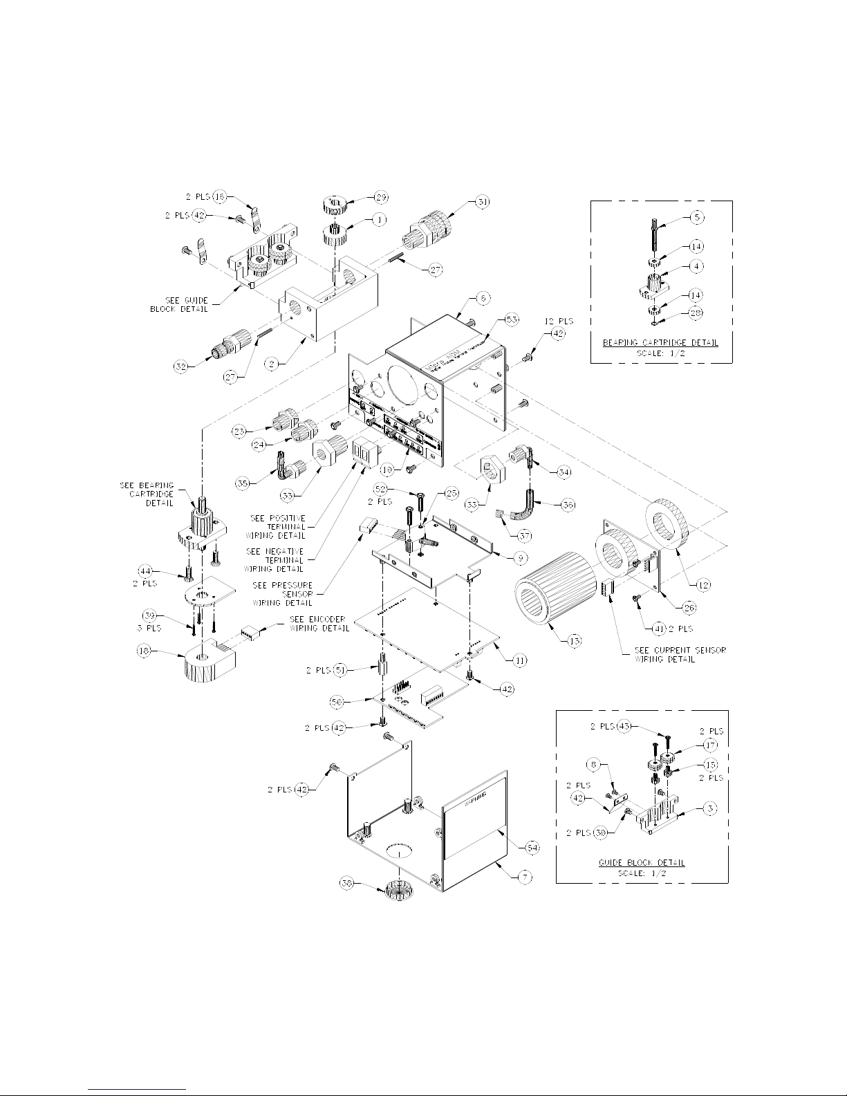
B.2 Micro ADM™ Sensor Assembly P/N: A3A0226 Rev: A
41
Page 46
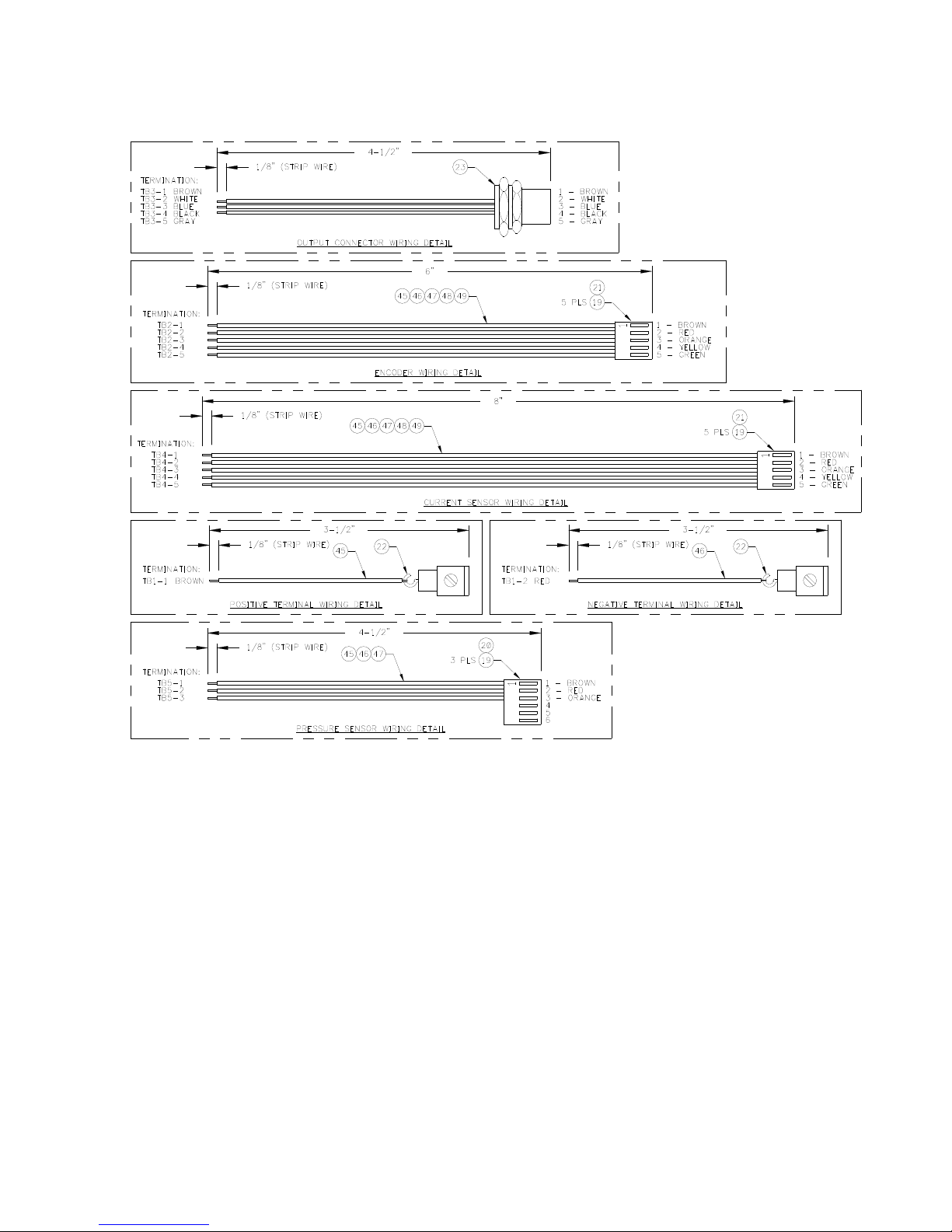
42
Page 47

PARTS LIST
ITEM QTY PART NUMBER DESCRIPTION
1 1 A2A0014 Driven Wheel
2 1 A2M0206 Transducer Block
3 1 A2M0203 Guide Block
4 1 A2M0204 Bearing Cartridge
5 1 A2M0205 WFS Shaft
6 1 A3E0159 Top Cover
7 1 A3E0160 Bottom Cover
8 1 A3E0141 Guide Handle
9 1 A3E0161 PCB Mounting Bracket
10 1 A3E0165 Micro ADM Status Overlay
11 1 A5A0109-MA Micro ADM PCB Assembly
12 1 A2M0207 Small Current Sensor Tube
13 1 A2M0208 Large Current Sensor Tube
14 2 X2B0373 Bearing #R4ZZ MRC
15 2 X2B5002 Stationary Bushing #B-1 Dua-L-Vee
16 2 X2N5023 Flat Spring #U-FS-2 Small Parts
17 2 X2P5004 Wheel #W1-X Dua-L-Vee
18 1 X3M5044 Encoder, Optical 256 cpr #HEDS-5500F06 Agilent
19 13 X3P5138 Crimp, Terminal #08-56-0110 Molex
20 1 X3P5224 Connector, Housing 6 circuit #22-01-2067 Molex
21 2 X3P5443 Connector, Housing 5 circuit #22-01-2057 Molex
22 2 X3P5767 Block, Terminal Series VDFK #0708250 Phoenix
23 1 X3P5805 Connector, RCPT 5 circuit #FS4.5-0.5 Turck
24 1 X3P5807 Connector, RCPT 8 circuit #FS8-0.5 Turck
25 1 X3Q5017 Pressure Sensor #MPX5100DP Motorola
26 1 X3Q5013 Hall Effect Current Sensor #BB-600 FW Bell
27 2 X6P5007 Dowel Pin, 0.093” diameter ¾” long #D2-6 Berg
28 1 X6B5025 Retaining Ring, ¼” External #5100-25 Thruarc
29 1 X6B5054 Shaft Collar #DSCA-5 Small Parts
30 2 X6B5055 Locator Button #CL-1-SLB Carr Lane
31 1 X6F5090 Fitting, Quick Disconnect #BST-2M Parker
32 1 X6F5102 Fitting, Nipple #BST-N2M Parker
33 1 X6F5119 Fitting, Coupling Anchor 1/8” NPT #207ACBHS-2 Parker
34 1 X6F5118 Fitting, Elbow 3/16” Hose 1/8” NPT #5013008 New Age
35 1 X6F5115 Fitting, Elbow 1/4” Hose 1/8” NPT #5013043 New Age
36 2.5” X6H5019 Tubing, Black 0.17” ID 0.25” OD #2121483 New Age
37 1 Clamp, Hose 1/4”
38 1 X6Z5092 Plug, Hole Short 7/8” Black #1699 Heyco
39 3 #0-80 x 3/8” long Philips Pan Head Screw
40 2 #4-40 x 1/2“ long Binder Head Screw
41 1 #4-40 x 5/16” long Pan Head Screw w/ Internal Lock Washer
42 21 #6-32 x 5/16” long Pan Head Screw w/ Internal Lock Washer
43 2 Fitting, Elbow 1/4” Hose 1/8” NPT #5013043 New Age
44 2 #8-32 x 1/2” long Socket Flat Head Screw
45 22” Wire, 24 AWG CSA Type Tr-64 Brown
46 22” Wire, 24 AWG CSA Type Tr-64 Red
47 18” Wire, 24 AWG CSA Type Tr-64 Orange
48 14” Wire, 24 AWG CSA Type Tr-64 Yellow
49 14” Wire, 24 AWG CSA Type Tr-64 Green
50 1 A5A0117 I-Dart I/O PCB Assembly
51 2 X6S5023 Spacer, M-F #6-32 x 1/2” long #8250 HH Smith
52 2 #6-32 x 5/8” long Pan Head Screw
53 1 Micro ADM Sensor Serial Number Label
54 1 Warning #1 Label
43
Page 48
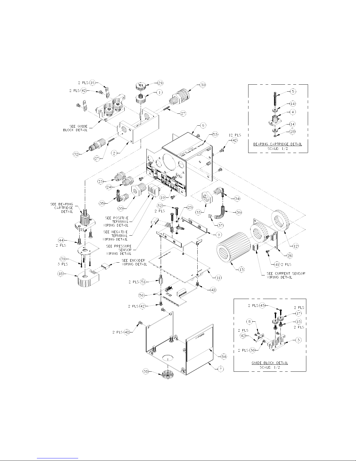
B.3 Micro ADM™ Sensor Assembly P/N: A3A0226 Rev: B
44
Page 49
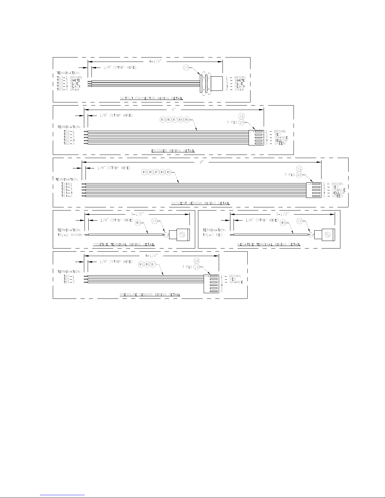
45
Page 50

PARTS LIST
ITEM QTY PART NUMBER DESCRIPTION
1 1 A2A0014 Driven Wheel
2 1 A2M0206 Transducer Block
3 1 A2M0203 Guide Block
4 1 A2M0204 Bearing Cartridge
5 1 A2M0205 WFS Shaft
6 1 A3E0159 Top Cover
7 1 A3E0160 Bottom Cover
8 1 A3E0141 Guide Handle
9 1 A3E0161 PCB Mounting Bracket
10 1 A3E0165 Micro ADM Status Overlay
11 1 A5A0109-MA Micro ADM PCB Assembly
12 1 A2M0207 Small Current Sensor Tube
13 1 A2M0208 Large Current Sensor Tube
14 2 X2B5070 Bearing #R4FF MRC
15 2 X2B5002 Stationary Bushing #B-1 Dua-L-Vee
16 2 X2N5023 Flat Spring #U-FS-2 Small Parts
17 2 X2P5004 Wheel #W1-X Dua-L-Vee
18 1 X3M5044 Encoder, Optical 256 cpr #HEDS-5500F06 Agilent
19 13 X3P5138 Crimp, Terminal #08-56-0110 Molex
20 1 X3P5224 Connector, Housing 6 circuit #22-01-2067 Molex
21 2 X3P5443 Connector, Housing 5 circuit #22-01-2057 Molex
22 2 X3P5767 Block, Terminal Series VDFK #0708250 Phoenix
23 1 X3P5805 Connector, RCPT 5 circuit #FS4.5-0.5 Turck
24 1 X3P5807 Connector, RCPT 8 circuit #FS8-0.5 Turck
25 1 X3Q5017 Pressure Sensor #MPX5100DP Motorola
26 1 X3Q5013 Hall Effect Current Sensor #BB-600 FW Bell
27 2 X6P5007 Dowel Pin, 0.093” diameter ¾” long #D2-6 Berg
28 1 X6B5025 Retaining Ring, ¼” External #5100-25 Thruarc
29 1 X6B5054 Shaft Collar #DSCA-5 Small Parts
30 2 X6B5055 Locator Button #CL-1-SLB Carr Lane
31 1 X6F5090 Fitting, Quick Disconnect #BST-2M Parker
32 1 X6F5102 Fitting, Nipple #BST-N2M Parker
33 1 X6F5119 Fitting, Coupling Anchor 1/8” NPT #207ACBHS-2 Parker
34 1 X6F5118 Fitting, Elbow 3/16” Hose 1/8” NPT #5013008 New Age
35 1 X6F5115 Fitting, Elbow 1/4” Hose 1/8” NPT #5013043 New Age
36 2.5” X6H5019 Tubing, Black 0.17” ID 0.25” OD #2121483 New Age
37 1 Clamp, Hose 1/4”
38 1 X6Z5092 Plug, Hole Short 7/8” Black #1699 Heyco
39 3 #0-80 x 3/8” long Philips Pan Head Screw
40 2 #4-40 x 1/2“ long Binder Head Screw
41 1 #4-40 x 5/16” long Pan Head Screw w/ Internal Lock Washer
42 21 #6-32 x 5/16” long Pan Head Screw w/ Internal Lock Washer
43 2 Fitting, Elbow 1/4” Hose 1/8” NPT #5013043 New Age
44 2 #8-32 x 1/2” long Socket Flat Head Screw
45 22” Wire, 24 AWG CSA Type Tr-64 Brown
46 22” Wire, 24 AWG CSA Type Tr-64 Red
47 18” Wire, 24 AWG CSA Type Tr-64 Orange
48 14” Wire, 24 AWG CSA Type Tr-64 Yellow
49 14” Wire, 24 AWG CSA Type Tr-64 Green
50 1 A5A0117 I-Dart I/O PCB Assembly
51 2 X6S5023 Spacer, M-F #6-32 x 1/2” long #8250 HH Smith
52 2 #6-32 x 5/8” long Pan Head Screw
53 1 Micro ADM Sensor Serial Number Label
54 1 Warning #1 Label
46
Page 51
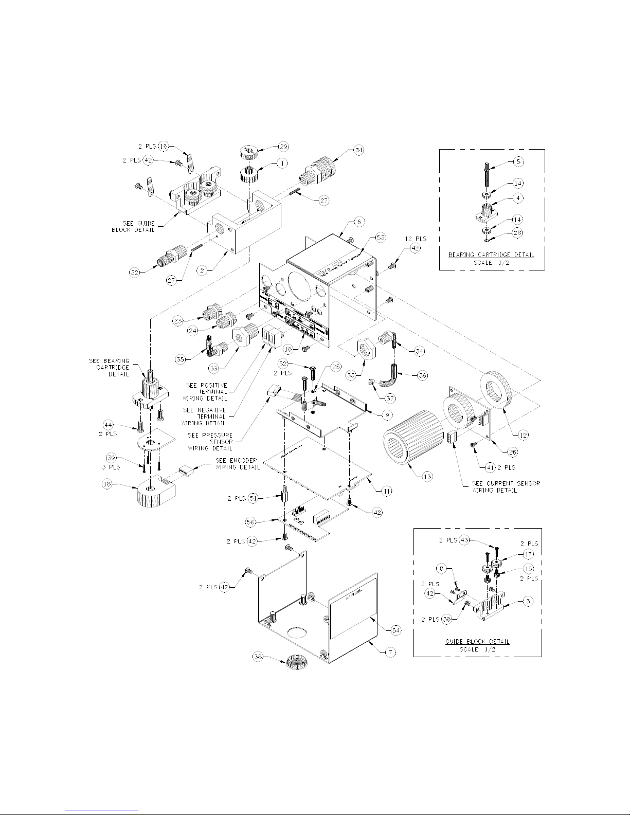
B.4 Micro ADM™ Sensor Assembly P/N: A3A0226 Rev: C
47
Page 52
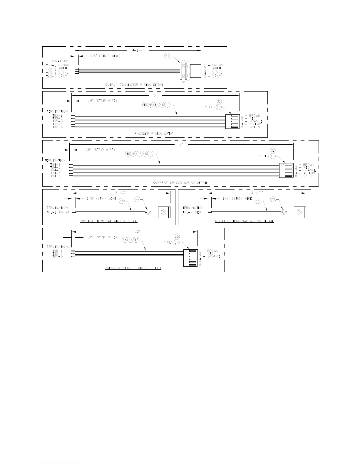
48
Page 53

PARTS LIST
ITEM QTY PART NUMBER DESCRIPTION
1 1 A2A0014 Driven Wheel
2 1 A2M0206 Transducer Block
3 1 A2M0203 Guide Block
4 1 A2M0204 Bearing Cartridge
5 1 A2M0205 WFS Shaft
6 1 A3E0159 Top Cover
7 1 A3E0160 Bottom Cover
8 1 A3E0141 Guide Handle
9 1 A3E0161 PCB Mounting Bracket
10 1 A3E0165 Micro ADM Status Overlay
11 1 A5A0109-MA Micro ADM PCB Assembly
12 1 A2M0207 Small Current Sensor Tube
13 1 A2M0208 Large Current Sensor Tube
14 2 X2B5070 Bearing #R4FF MRC
15 2 X2B5002 Stationary Bushing #B-1 Dua-L-Vee
16 2 X2N5023 Flat Spring #U-FS-2 Small Parts
17 2 X2P5004 Wheel #W1-X Dua-L-Vee
18 1 X3M5044 Encoder, Optical 256 cpr #HEDS-5500F06 Agilent
19 13 X3P5138 Crimp, Terminal #08-56-0110 Molex
20 1 X3P5224 Connector, Housing 6 circuit #22-01-2067 Molex
21 2 X3P5443 Connector, Housing 5 circuit #22-01-2057 Molex
22 2 X3P5767 Block, Terminal Series VDFK #0708250 Phoenix
23 1 X3P5805 Connector, RCPT 5 circuit #FS4.5-0.5 Turck
24 1 X3P5807 Connector, RCPT 8 circuit #FS8-0.5 Turck
25 1 X3Q5017 Pressure Sensor #MPX5100DP Motorola
26 1 X3Q5013 Hall Effect Current Sensor #BB-600 FW Bell
27 2 X6P5007 Dowel Pin, 0.093” diameter ¾” long #D2-6 Berg
28 1 X6B5025 Retaining Ring, ¼” External #5100-25 Thruarc
29 1 X6B5054 Shaft Collar #DSCA-5 Small Parts
30 2 X6B5055 Locator Button #CL-1-SLB Carr Lane
31 1 X6F5090 Fitting, Quick Disconnect #BST-2M Parker
32 1 X6F5102 Fitting, Nipple #BST-N2M Parker
33 1 X6F5119 Fitting, Coupling Anchor 1/8” NPT #207ACBHS-2 Parker
34 1 X6F5118 Fitting, Elbow 3/16” Hose 1/8” NPT #5013008 New Age
35 1 X6F5115 Fitting, Elbow 1/4” Hose 1/8” NPT #5013043 New Age
36 2.5” X6H5019 Tubing, Black 0.17” ID 0.25” OD #2121483 New Age
37 1 Clamp, Hose 1/4”
38 1 X6Z5092 Plug, Hole Short 7/8” Black #1699 Heyco
39 3 #0-80 x 3/8” long Philips Pan Head Screw
40 2 #4-40 x 1/2“ long Binder Head Screw
41 1 #4-40 x 5/16” long Pan Head Screw w/ Internal Lock Washer
42 21 #6-32 x 5/16” long Pan Head Screw w/ Internal Lock Washer
43 2 Fitting, Elbow 1/4” Hose 1/8” NPT #5013043 New Age
44 2 #8-32 x 1/2” long Socket Flat Head Screw
45 22” Wire, 24 AWG CSA Type Tr-64 Brown
46 22” Wire, 24 AWG CSA Type Tr-64 Red
47 18” Wire, 24 AWG CSA Type Tr-64 Orange
48 14” Wire, 24 AWG CSA Type Tr-64 Yellow
49 14” Wire, 24 AWG CSA Type Tr-64 Green
50 1 A5A0117 I-Dart I/O PCB Assembly
51 2 X6S5023 Spacer, M-F #6-32 x 1/2” long #8250 HH Smith
52 2 #6-32 x 5/8” long Pan Head Screw
53 1 Micro ADM Sensor Serial Number Label
54 1 Warning #1 Label
49
Page 54
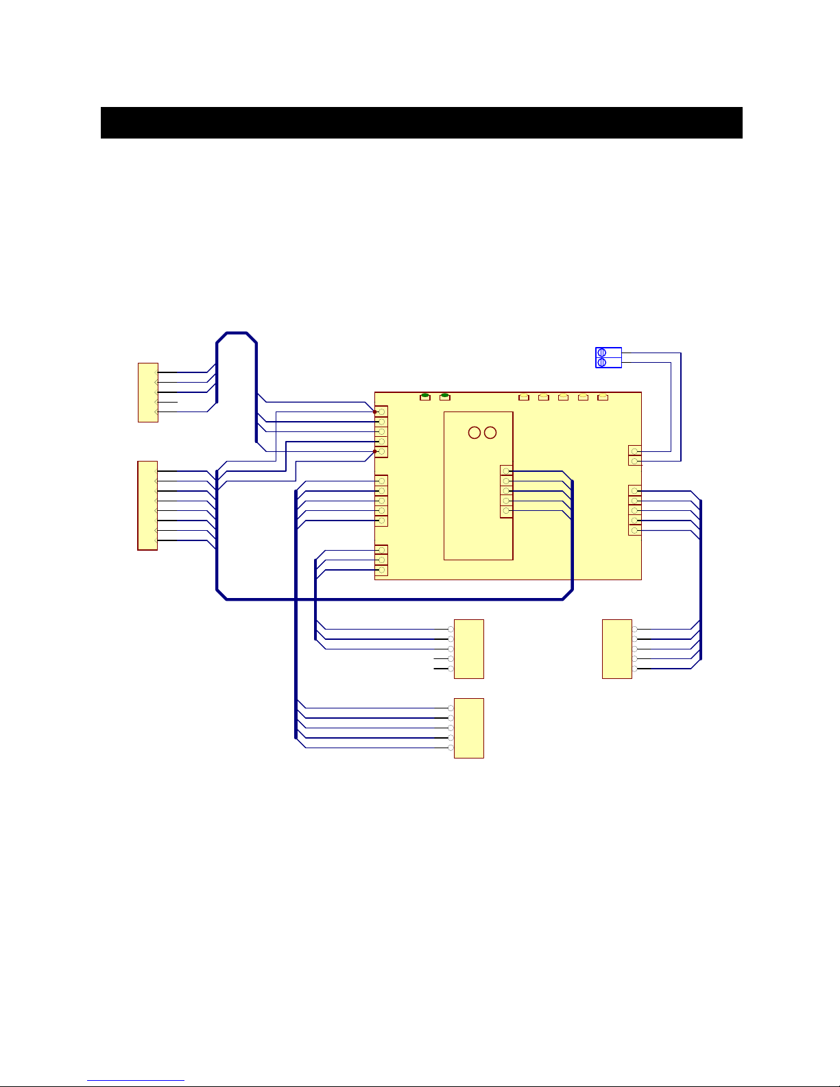
Appendix C Schematic Diagrams
C.1 Micro ADM™ Sensor Assembly P/N: A3A0226 Rev: 0
P1
BRN
1
+24
NET+
NETN.C.
COM
CR1
+24
CR2
CR3
COM
INP1
INP2
ICOM
SENSOR
WHT
2
BLU
3
BLK
4
GRY
5
P2
WHT
1
BRN
2
GRN
3
YEL
4
GRY
5
PNK
6
BLU
7
RED
8
I/O
BRN
PNK
GRY
BRN
BRN
WHT
BLU
PNK
GRY
GRY
BRN
RED
ORG
GRN
BRN
RED
ORG
PCB?
TB3
+24 +5 A MP VOL
1 +24
2 NET+
3 NET4 INP1
5 COM
TB4
1 AMP+
2 AMP3 COM
4 -15 V
5 +15 V
TB5
1 GAS+
2 COM
3 +5V
MICRO ADM P C B
MSB LSB
CR1 1
CR2 2
CR3 3
INP2 4
COM 5
I/O PCB
A5A0117
TB6
GAS
WHT
GRN
YE
BLU
RED
L
+VARC
-VARC
RDYWFS
I-DART PCB
A5A0109
+VARC 1
TB7
1
2
VOLT SENSE
-VARC 2
INDEX 5
+5V 4
CHA 3
CHB 2
COM 1
TB1
TB2
BRN
RED
RED
BRN
GRN
YEL
ORGYEL
RED
BRN
BRN
RED
ORG
BRN
RED
ORG
YEL
GRN
P4
1
2
3
4
5
GAS SENSOR
P3
1
2
3
4
5
AMP SENSOR
S+
GA
ACOM
+5 VDC
N.C.
N.C.
AMP+
AMPACOM
-15 VDC
+15 VDC
COM
CHB
CHA
+5 VDC
DCOM
P5
1
2
3
4
5
ENCODER
BRN
RED
ORG
YEL
GRN
50
Page 55
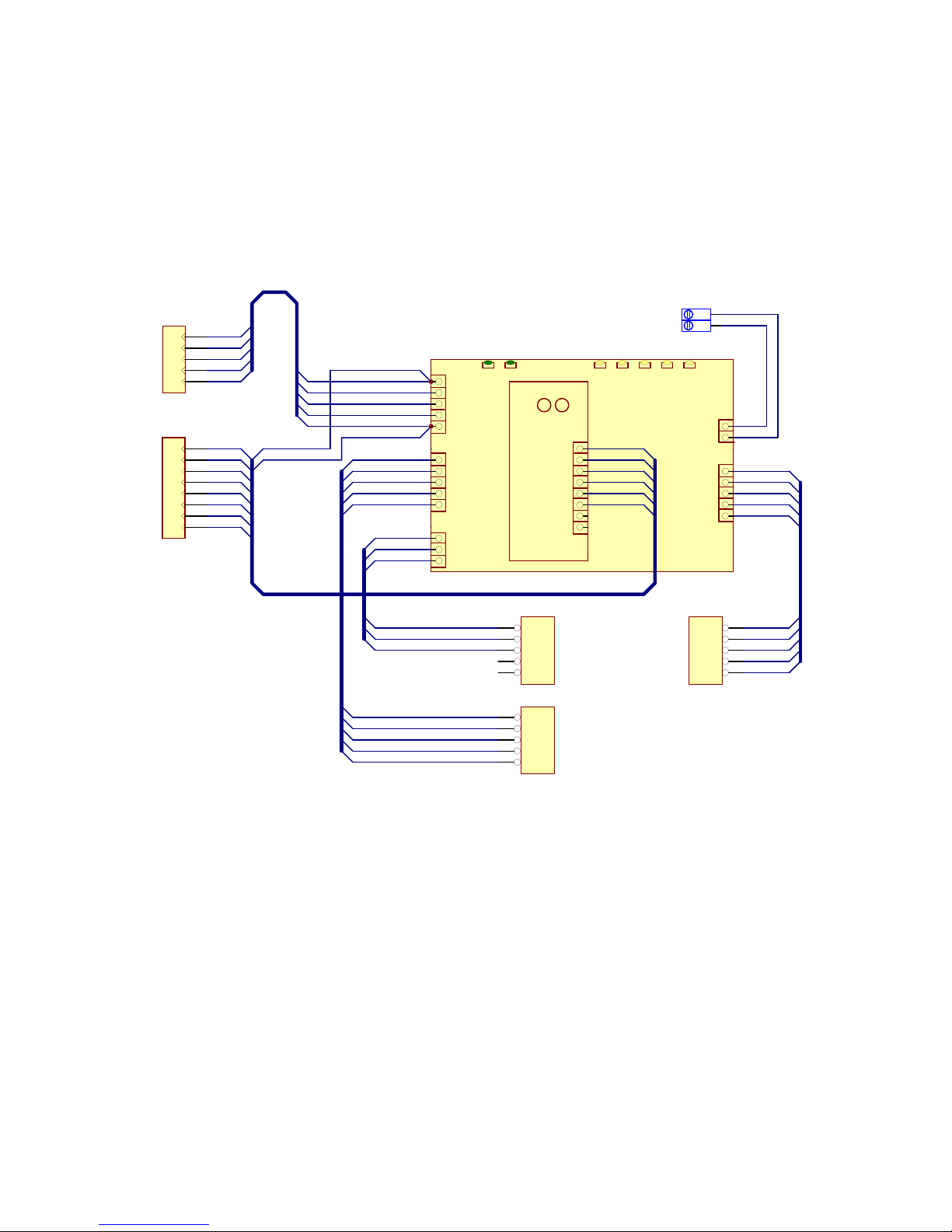
C.2 Micro ADM™ Sensor Assembly P/N: A3A0226 Rev: A
TB7
WHT
YEL
GRN
BLU
RED
PNK
+VARC
-VARC
RDYWFS
I-DART PCB
A5A0109
+VARC 1
VOLT SENSE
-VARC 2
INDEX 5
CHA 3
CHB 2
COM 1
+24
NET+
NETN.C.
COM
CR1
+24
CR2
CR3
COM
INP1
INP2
ICOM
P1
SENSOR
P2
BRN
1
WHT
2
BLU
3
BLK
4
GRY
5
WHT
1
BRN
2
GRN
3
YEL
4
GRY
5
PNK
6
BLU
7
RED
8
I/O
ADM?
BRN
TB3
BRN
WHT
BLU
BL
K
GRY
GRY
TB4
BRN
RED
ORG
GRN
TB5
BRN
RED
ORG
ICRO ADM REV A PCB
M
+24 +5 A MP VOL
1 +24
2 NET+
3 NET4 INP0
5 COM
1 AMP+
2 AMP3 COM
4 -15 V
5 +15 V
1 GAS+
2 COM
3 +5V
MSB LSB
CR1 1
CR3 2
CR2 3
INP1 4
INP2 5
INP3 6
+24V 7
COM 8
I/O PCB
A5A0117
GAS
TB6
1
2
+5V 4
TB1
TB2
BRN
RED
RED
BRN
GRN
YEL
ORGYEL
RED
BRN
BRN
RED
ORG
BRN
RED
ORG
YEL
GRN
P4
1
2
3
4
5
GAS SENSOR
P3
1
2
3
4
5
AMP SENSOR
GAS+
ACOM
+5 VDC
N.C.
N.C.
AMP+
AMPACOM
-15 VDC
+15 VDC
COM
CHB
CHA
+5 VDC
DCOM
P5
1
2
3
4
5
ENCODER
BRN
RED
ORG
YEL
GRN
51
Page 56
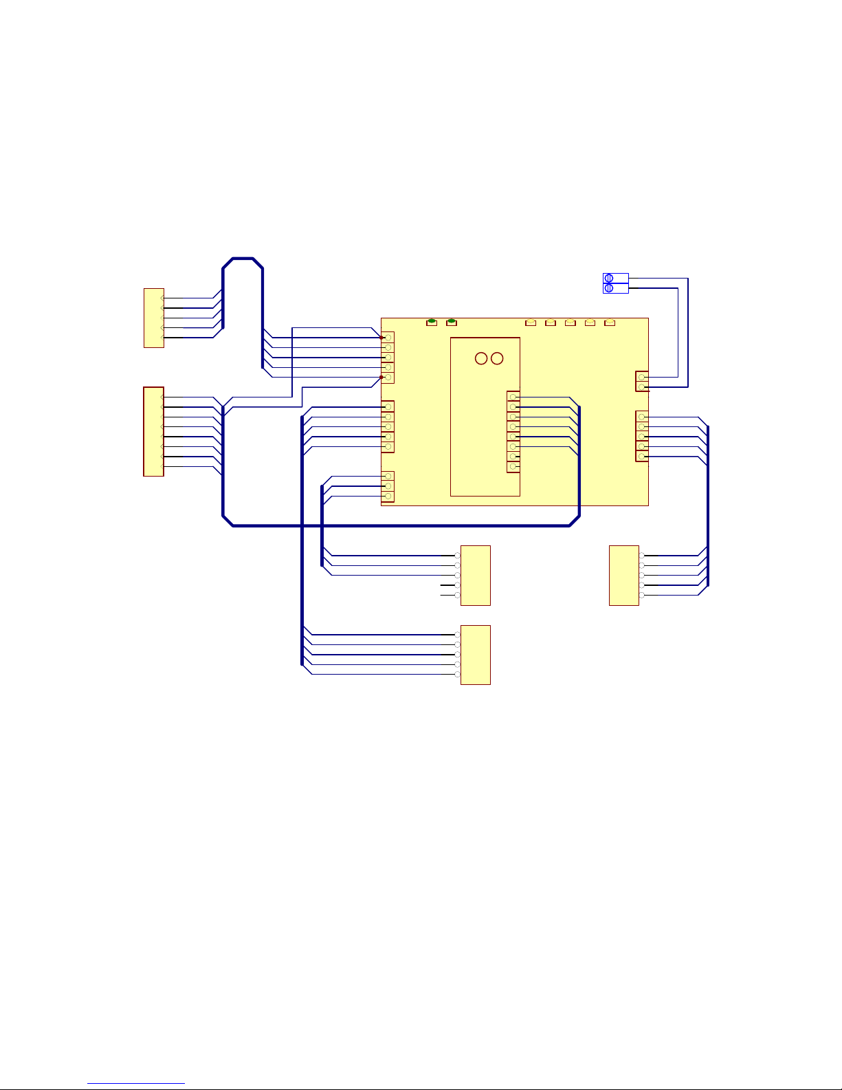
C.3 Micro ADM™ Sensor Assembly P/N: A3A0226 Rev: B
TB7
WHT
YEL
GRN
BLU
RED
PNK
+VARC
-VARC
RDYWFS
I-DART PCB
A5A0109
+VARC 1
VOLT SENSE
-VARC 2
INDEX 5
CHA 3
CHB 2
COM 1
+24
NET+
NETN.C.
COM
CR1
+24
CR2
CR3
COM
INP1
INP2
ICOM
P1
SENSOR
P2
BRN
1
WHT
2
BLU
3
BLK
4
GRY
5
WHT
1
BRN
2
GRN
3
YEL
4
GRY
5
PNK
6
BLU
7
RED
8
I/O
ADM?
BRN
TB3
BRN
WHT
BLU
BL
K
GRY
GRY
TB4
BRN
RED
ORG
GRN
TB5
BRN
RED
ORG
ICRO ADM REV A PCB
M
+24 +5 A MP VOL
1 +24
2 NET+
3 NET4 INP0
5 COM
1 AMP+
2 AMP3 COM
4 -15 V
5 +15 V
1 GAS+
2 COM
3 +5V
MSB LSB
CR1 1
CR3 2
CR2 3
INP1 4
INP2 5
INP3 6
+24V 7
COM 8
I/O PCB
A5A0117
GAS
TB6
1
2
+5V 4
TB1
TB2
BRN
RED
RED
BRN
GRN
YEL
ORGYEL
RED
BRN
BRN
RED
ORG
BRN
RED
ORG
YEL
GRN
P4
1
2
3
4
5
GAS SENSOR
P3
1
2
3
4
5
AMP SENSOR
GAS+
ACOM
+5 VDC
N.C.
N.C.
AMP+
AMPACOM
-15 VDC
+15 VDC
COM
CHB
CHA
+5 VDC
DCOM
P5
1
2
3
4
5
ENCODER
BRN
RED
ORG
YEL
GRN
52
Page 57
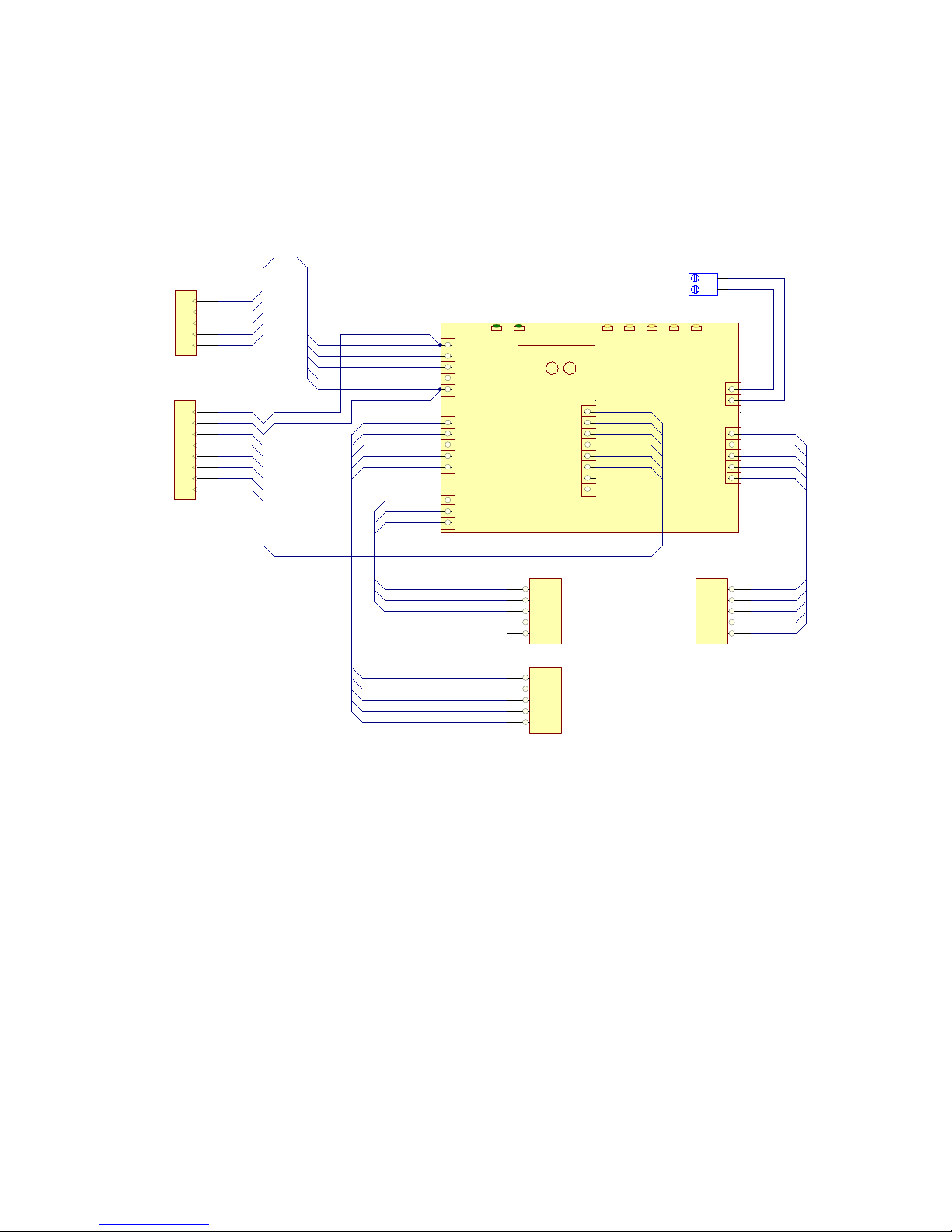
C.4 Micro ADM™ Sensor Assembly P/N: A3A0226 Rev: C
TB7
RDYWFS
+VARC 1
1
2
VOLT SENSE
-VARC 2
INDEX 5
+5V 4
CHA 3
CHB 2
COM 1
+24
NET+
NETPSEL
COM
CR1
+24
CR2
CR3
COM
INP1
INP2
ICOM
P1
1
2
3
4
5
SENSOR
P2
1
2
3
4
5
6
7
8
I/O
BRN
WHT
BLU
BLK
GRY
WHT
BRN
GRN
YEL
GRY
PNK
BLU
RED
ADM?
BRN
TB3
BRN
WHT
BLU
BLK
GRY
GRY
BRN
RED
ORG
GRN
BRN
RED
ORG
1 +24
2 NET+
3 NET4 INP0
5 COM
TB4
1 AMP+
2 AMP3 COM
4 -15 V
5 +15 V
TB5
1 GAS+
2 COM
3 +5V
MICRO ADM REV A PCB
+VARC
-VARC
+24 +5 AMP VOL
MSB LS B
CR1 1
CR3 2
CR2 3
INP1 4
INP2 5
INP3 6
+24V 7
COM 8
I/O PCB
A5A0117
TB6
GAS
WHT
YEL
GRN
BLU
RED
PNK
I-DART PCB
A5A0109
TB1
TB2
BRN
RED
RED
BRN
GRN
YEL
ORGYEL
RED
BRN
BRN
RED
ORG
BRN
RED
ORG
YEL
GRN
P4
1
2
3
4
5
GAS SE NSOR
P3
1
2
3
4
5
AMP SENS OR
GAS+
ACOM
+5 VDC
N.C.
N.C.
AMP+
AMPACOM
-15 VDC
+15 VDC
COM
CHB
CHA
+5 VDC
DCOM
P5
1
2
3
4
5
ENCODER
BRN
RED
ORG
YEL
GRN
53
Page 58
Appendix D Device ID MSB and LSB Decode Table
Node ID MSB LSB Node ID MSB LSB Node ID MSB LSB Node ID MSB LSB
1 0 1 63 3 F 124 7 D 187 B B
2 0 2 64 4 0 125 7 E 188 B C
3 0 3 65 4 1 126 7 F 189 B D
4 0 4 66 4 2 127 8 0 190 B E
5 0 5 67 4 3 128 8 1 191 B F
6 0 6 68 4 4 129 8 2 192 C 0
7 0 7 69 4 5 130 8 3 193 C 1
8 0 8 70 4 6 131 8 4 194 C 2
9 0 9 71 4 7 132 8 5 195 C 3
10 0 A 72 4 8 133 8 6 196 C 4
11 0 B 73 4 9 134 8 7 197 C 5
12 0 C 74 4 A 135 8 8 198 C 6
13 0 D 75 4 B 136 8 9 199 C 7
14 0 E 76 4 C 137 8 A 200 C 8
15 0 F 77 4 D 138 8 B 201 C 9
16 1 0 78 4 E 139 8 C 202 C A
17 1 1 79 4 F 140 8 D 203 C B
18 1 2 80 5 0 141 8 E 204 C C
19 1 3 81 5 1 142 8 F 205 C D
20 1 4 82 5 2 143 9 0 206 C E
21 1 5 83 5 3 144 9 1 207 C F
22 1 6 94 5 4 145 9 2 208 D 0
23 1 7 85 5 5 146 9 3 209 D 1
24 1 8 86 5 6 147 9 4 210 D 2
25 1 9 86 5 7 148 9 5 211 D 3
26 1 A 87 5 8 149 9 6 212 D 4
27 1 B 88 5 9 150 9 7 213 D 5
28 1 C 89 5 A 151 9 8 214 D 6
29 1 D 90 5 B 152 9 9 215 D 7
30 1 E 91 5 C 153 9 A 216 D 8
31 1 F 92 5 D 154 9 B 217 D 9
32 2 0 93 5 E 155 9 C 218 D A
33 2 1 94 5 F 156 9 D 219 D B
34 2 2 95 6 0 157 9 E 220 D C
35 2 3 96 6 1 158 9 F 221 D D
36 2 4 97 6 2 159 A 0 222 D E
37 2 5 98 6 3 160 A 1 223 D F
38 2 6 99 6 4 161 A 2 224 E 0
39 2 7 100 6 5 162 A 3 225 E 1
40 2 8 101 6 6 163 A 4 226 E 2
41 2 9 102 6 7 164 A 5 227 E 3
42 2 A 103 6 8 165 A 6 228 E 4
43 2 B 104 6 9 166 A 7 229 E 5
44 2 C 105 6 A 167 A 8 230 E 6
45 2 D 106 6 B 168 A 9 231 E 7
46 2 E 107 6 C 170 A A 232 E 8
47 2 F 108 6 D 171 A B 233 E 9
48 3 0 109 6 E 172 A C 234 E A
49 3 1 110 6 F 173 A D 235 E B
50 3 2 111 7 0 174 A E 236 E C
51 3 3 112 7 1 175 A F 237 E D
52 3 4 113 7 2 176 B 0 238 E E
53 3 5 114 7 3 177 B 1 239 E F
54 3 6 115 7 4 178 B 2 240 F 0
55 3 7 116 7 5 179 B 3 241 F 1
56 3 8 117 7 6 180 B 4 242 F 2
57 3 9 118 7 7 181 B 5 243 F 3
58 3 A 119 7 8 182 B 6 244 F 4
59 3 B 120 7 9 183 B 7 245 F 5
60 3 C 121 7 A 184 B 8 246 F 6
61 3 D 122 7 B 185 B 9 247 F 7
62 3 E 123 7 C 186 B A
54
 Loading...