

Page 1
S/N:9978623807A
COLOR MONITOR
Model No : CTL 5fln
CTL
USERS GUIDE
Page 2
1. Read all of these instructions.
2. Save these instructions for later use.
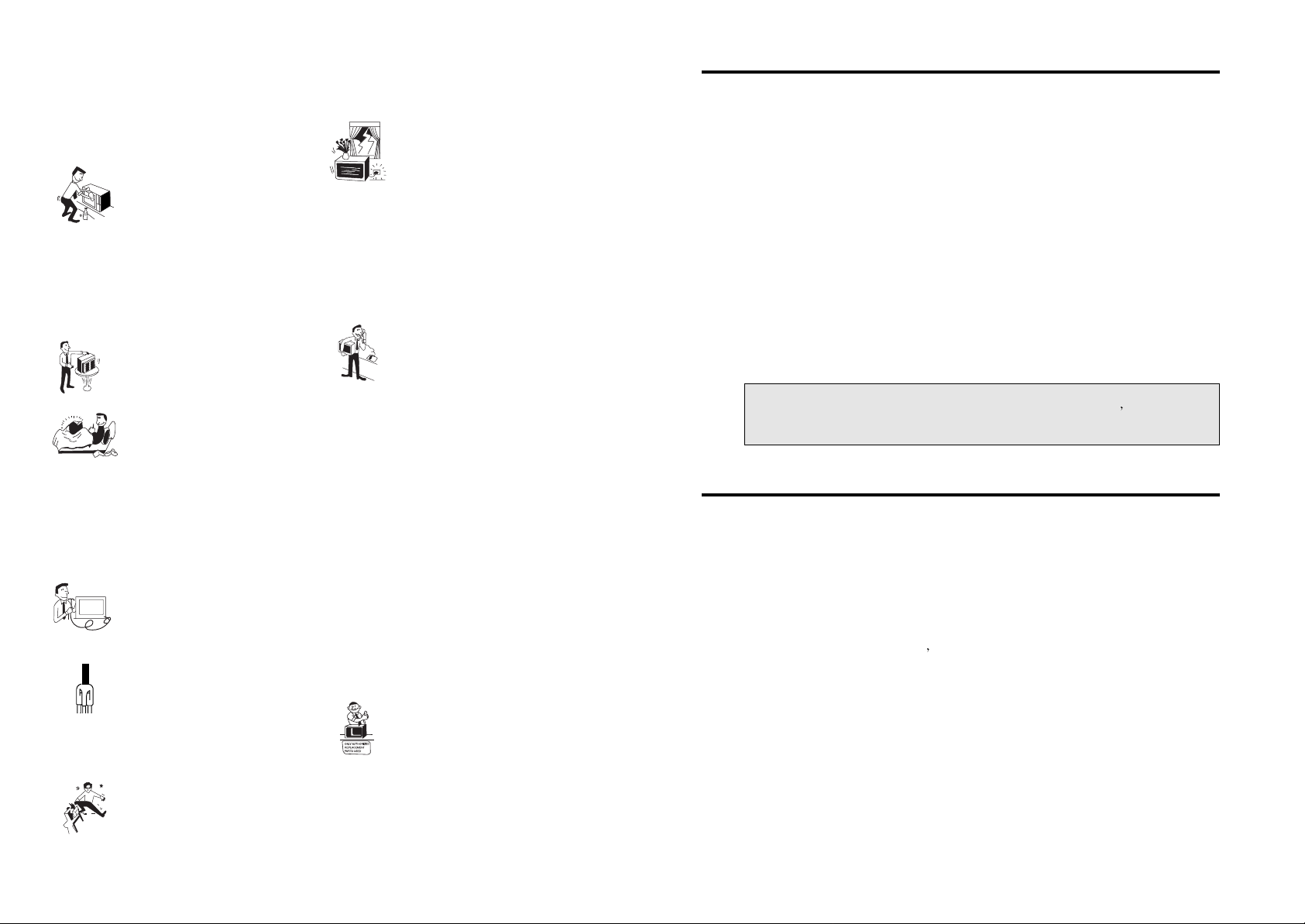
3. Unplug this monitor from the
wall outlet before cleaning. Do not
use liquid cleaners or aerosol
cleaners. Use a damp cloth for
cleaning.
4. Do not use attachments not recommended by
the monitor manufacturer as they may cause
hazards.
5. Do not use this monitor near water for
example, near a bathtub, washbowl, kitchen sink,
or laundry tub, in a wet basement or near a
swimming pool, etc.
6. Do not place this monitor on an
unstable cart, stand, or table. The
monitor may fall, causing serious
injury to a child or adult, and
serious damage to the appliance.
7. Slots and openings in the cabinet
and the back or bottom are
provided for ventilation, and to
ensure reliable operation of the
monitor and to protect it from
overheating, these openings must not be blocked
or covered. The openings should never be
blocked by placing the monitor on a bed, sofa,
rug, or other similar surface. This should never
be placed near or over a radiator or heat register.
This monitor should not be placed in a built-in
installation such as a bookcase unless proper
ventilation is provided.
8. This monitor should be operated
only from the type of power source
indicated on the marking label. If
you are not sure of the power
supplied to your home, consult
your monitor dealer or local power company.
9. This monitor is equipped with a
3-wire grounding type plug, a plug
having a third (grounding) pin. This
plug will only fit into a
groundingtype power outlet. This is
a safety feature. If you are unable to insert the
plug into the outlet, contact your electrician to
replace your obsolete outlet. Do not defeat the
purpose of the groundingtype plug.
10. Do not allow anything to rest
on the power cord. Do not locate
this monitor where the cord will be
abused by persons walking on it.
11. Follow all warnings and instructions marked
on the monitor.
IMPORTANT SAFEGUARDS
12. For added protection for this
monitor during a lightning storm,
or when it is left unattended and
unused for long periods of time,
unplug it from the wall outlet. This
will prevent damage to the set due to lightning
and powerline surges.
13. Do not overload wall outlets and extension
cords as this can result in fire or electric shock.
14. Never push objects of any kind into this
monitor through cabinet slots, as they may touch
dangerous voltage points or short out parts that
could result in a fire or electric shock. Never spill
liquid of any kind on the monitor.
15. Do not attempt to service this
monitor yourself as opening or
removing covers may expose you
to dangerous voltage or other
hazards. Refer all servicing to
qualified service personnel.
16. Unplug this monitor from the wall outlet and
refer servicing to qualified service personnel
under the following conditions:
a. When the power cord or plug is damaged or
frayed.
b. If liquid has been spilled into the monitor.
c. If the monitor has been exposed to rain or
water.
d. If the monitor does not operate normally by
following the operating instructions. Adjust only
those controls that are covered by the operating
instructions as improper adjustment of other
controls may result in damage and will often
require extensive work by a qualified technician
to restore normal operation.
e. If the monitor has been dropped or the cabinet
has been damaged.
f. When the monitor exhibits a distinct change in
performance this indicates a need for service.
17. When replacement parts are
required be sure the service
technician has used replacement
parts specified by the manufacturer
that have the same characteristics
as the original part. Unauthorized substitutions
may result in fire, electric shock, or other
hazards.
18. Upon completion of any service or repairs to
this monitor, ask the service technician to
perform routine safety checks to determine that
the monitor is in safe operating condition.
FEDERAL COMMUNICATIONS COMMISSION
RADIO FREQUENCY INTERFERENCE STATEMENT
NOTE : This equipment has been tested and found to comply with the limits for a
Class B digital device, prusuant to Part 15 of the FCC Rules. These limits in a
residential installation. This equipment generates, uses and can radiate radio
frequency energy and, if not installed and used in accordance with the instructions,
may cuase harmful interference to radio communications. However, there is no
guarantee that interference will not occur in a particular installation. If this
equipment does cause harmful interference to radio or television reception, which
can be determined by turning the equipment off and on, the user is encouraged to
try to correct the interference by one or more of the following measures :
- Reorient or relocate the receiving antenna.
- Increase the separation between the equipment and receiver.
- Connect the equipment to an outlet on a circuit different from that to which the
receiver is connected.
- Consult the dealer or an experienced radio, TV technician for help.
CAUTION : Any changes or modifications not expressly approved by the
part responsible for compliance could void the user
s authority
to operate the equipment.
CANADIAN DEPARTMENT OF COMMUNICATIONS
COMPLIANCE STATEMENT
This digital apparatus does not exceed the Class A/Class B (whichever is applicable)
limits for radio noise emissions from digital apparatus set out in the Radio
Interference Regulations of the Canadian Department of Communications.
Avis de conformité aux normes du Ministère des Communications du Canada.
Le present appareil numérique n
emet pas de bruits radioélectriques depassant les
limites applicables aux appareils numériques de Class A/de Class B (selon le cas)
prescrites dans le règlement sur le brouillage radioélectrique édicte par le ministère
des communications du canada.
Page 3
The power cord is used as a main disconnect device. Disconnect the power
cord before servicing.
The outlet must be installed near the monitor and must be easily accessible.
As an ENERGY STAR Partner, Computer Technology Link, Inc., has
determined that this product meets the Energy Star guidelines for energy
efficiency.
Page 4
Introduction 1
Product Features 2
Setup 3
Installing the Tilt/Swivel Stand 3
Connecting the D-Sub Signal Cable 4
Connecting to Your Macintosh Computer 4
Connecting the Power Cord 4
Power Management System 5
DDC for Plug & Play 5
Operation & Adjustment 6
Specifications 10
Factory Preset Timings 11
Troubleshooting 12
Description for D-sub Connector 13
CONTENTS
1
This manual explains how to correctly install, operate and get the best
performance from your monitor. Please read this user s manual carefully
before installing your monitor, then keep it near your monitor for quick
reference.
First, please check that the contents of the carton box corresponds with the
following checklist :
• Color monitor
• Power cord
• Tilt/swivel stand
• User s manual
• Warranty Handbook & Warranty Registration Card
If there is any item missing or damaged, please contact your dealer. Please
keep the carton box and packing materials so that you may properly store or
transport your monitor.
INTRODUCTION
Page 5
2
PRODUCT FEATURES
• The convenient and user-friendly on-screen display allows for
easy and accurate adjustments of horizontal and vertical screen
size and position, geometry and screen color.
• The monitor supports a safe working environment in strict
compliance with the MPR
standard for low emissions(TCO
1995 is optional).
• The monitor complies with the VESA Display Data
Channel(DDC) specification for
Plug & Play compatibility.
Advanced microcircuitry makes set-up and configuration fast and
effortless.
• The monitor features Advanced Color Controls for fine-tuning to
meet your own personal tastes or application requirements. Use
the on-screen controls to adjust the color temperature or RGB
gain value for the best possible screen color and intensity.
• Just activate the higher refresh rates of the monitor to stabilize the
screen and eliminate the annoying flicker that contributes to eyestrain and headaches.
• The
borderless full-screen display capability works under all
graphic modes and provides a larger viewing area than
conventional monitors, giving you a better picture with more
workspace.
3
SETUP
INSTALLING THE TILT/SWIVEL STAND
1. Ensure that the power to the monitor is off.
2. Set the monitor face down with the underside facing you. Please
be careful so as not to scratch the monitor screen.
3. Align the four hooks on the stand with the guide holes of bottom
chassis of the monitor.
4. Insert the hooks into the guide holes.
5. Slide the tilt/swivel stand toward the front of the monitor until the
latch locks in position.
6. Turn the monitor and the stand upright.
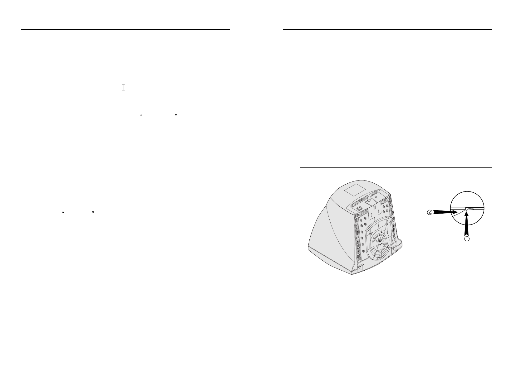
If you want to remove the tilt/swivel stand on the monitor, press the latch
and pull the tilt/swivel stand toward the back of the monitor. Lift the stand
to separate.
<Removing the tilt/swivel stand>
PUSH
PUSH
Page 6
4
CONNECTING THE D-SUB SIGNAL CABLE
1. Turn off the computer and monitor.
2. Connect the 15 pin D-sub connector to the output port of the
video card in your computer.
3. Tighten the screws of connector.
CONNECTING TO YOUR MACINTOSH COMPUTER
1. Turn off the computer and monitor.
2. Attach the Macintosh cable adapter to the Macintosh video card.
3. Tighten the screws on the cable adapter.
4. Connect the signal cable provided with your monitor to the other
end of the Macintosh cable adapter.
5. Tighten the screws between the Macintosh cable adapter and the
signal cable.
CONNECTING THE POWER CORD
1. Plug the power cord into the AC receptacle located at the back of
the monitor.
2. Plug the other end of the power cord into the AC outlet.
If your power cord is PC to Monitor type, plug the other end of the
power cord into the AC receptacle in the computer.
5
POWER MANAGEMENT SYSTEM
If you use the monitor with a computer which complies with the power
saving program, you can set the monitor to go blank when the system has
remained unused for a period of time. To specify the period or to disable
this feature, set the system timeout field of the computer s system setup
program or use special software for power saving. See the computer user s
manual for the details of using the system setup. While the monitor is in
power saving mode (blank screen), it consumes less power than normal
state; the color of the power LED will indicate the state. To restore the
screen image, press any key of your keyboard or move your mouse. If the
signal cable is connected loosely or disconnected, the power saving feature
will operate.
DISPLAY DATA CHANNEL (DDC) FOR PLUG & PLAY
If you use the monitor with a computer which complies with DDC1/2B of
VESA, the Host-Video Card automatically configures itself without your
intervention in a way that best fits the attached monitor. The Display Data
Channel, DDC, allows the monitor to inform the host system about
configuration information for optimum use of the monitor. Use of the
Video Card utility is not required to match the resolutions and refresh rates
of the monitor and video card.
Page 7
6
OPERATION & ADJUSTMENT
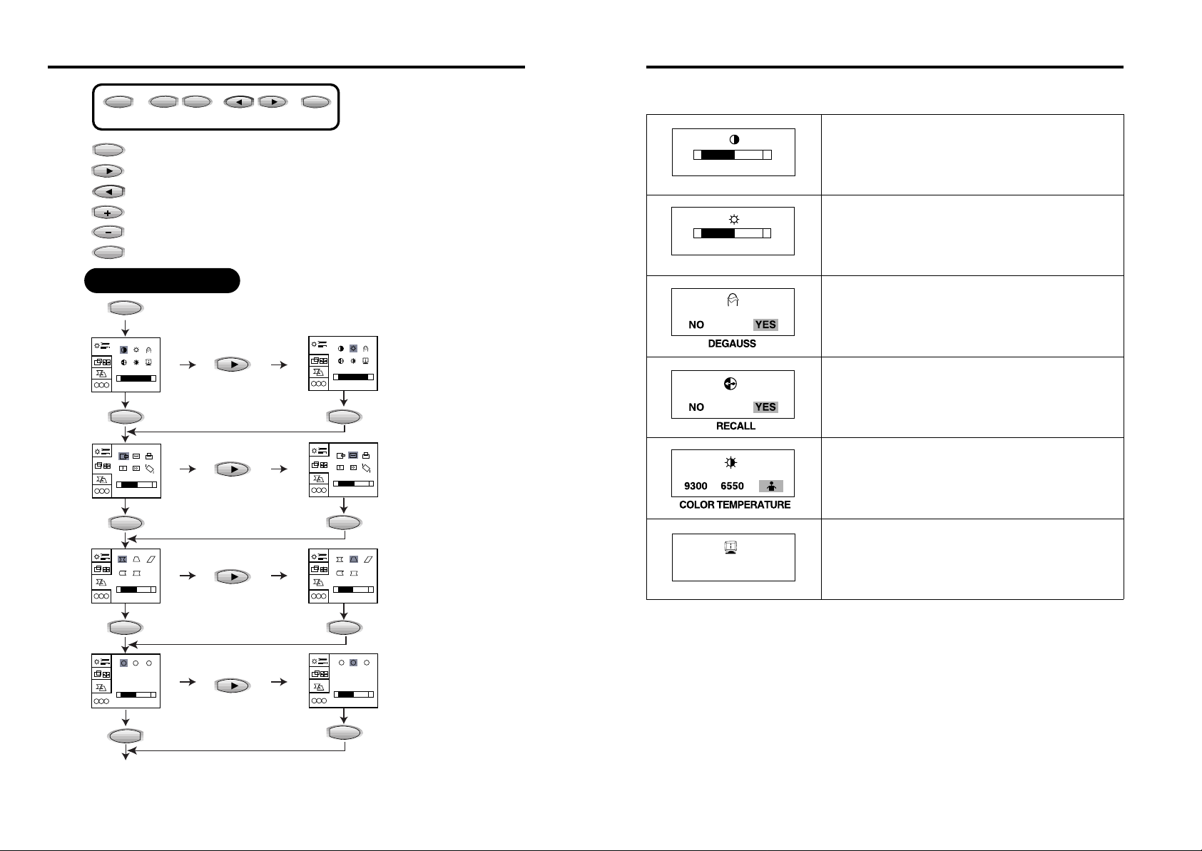
: Launch OSD(On-Screen Display) Menus
: Select the next function
: Select the previous function
: Increase the value of any selected function
: Decrease the value of any selected function
: Exit OSD Menus & Launch OSD Menus, when no OSD
EXIT
ADJUST SELECT
MENU
-
+
MENU
Key Process
R
B
G
–
+
100%
R
B
G
–
+
50%
R
B
G
–
+
50%
R
B
G
B
G
–
+
50%
R
R
B
G
–
+
100%
R
B
G
–
+
50%
R
B
G
–
+
50%
R
B
G
B
–
+
50%
R
G
OSD OFF
MENU
MENU MENU
MENU
MENU MENU
MENU
EXIT
MENU
EXIT
7
1. OSD(On-Screen Display) Menu 1
-
+
50%
CONTRAST
-
+
50%
BRIGHTNESS
H:+37.6KHz
V:+72Hz
STATUS
Adjust the contrast of image, the difference
between light and dark areas on the screen.
Range : 0 -100 %
Adjust the brightness of the entire display.
Degauss the display and restore image quality.
Reset the screen to the Factory Preset Display
Settings.
Choose different preset color temperatures or set
your own customized color parameters.
Display horizontal & vertical frequency and
polarity.
Page 8
8
2. OSD (On-Screen Display) Menu 2
-
+
50%
HORIZONTAL POSITION
-
+
50%
HORIZONTAL SIZE
-
+
50%
VERTICAL POSITION
-
+
50%
VERTICAL SIZE
-
+
50%
MOIRE
-
+
50%
TILT
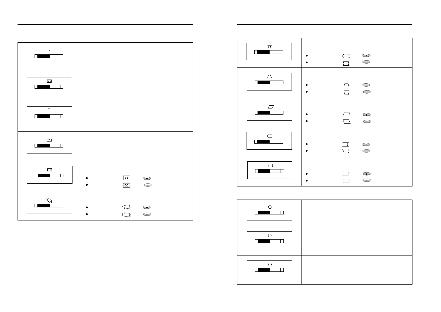
Adjust the position of the display horizontally
(left or right).
Adjust the display width (horizontal size).
Adjust the position of the display vertically (up
or down).
Adjust the display height (vertical size).
Eliminate a moire pattern looking like a series of
concentric circles or arcs.
Image turns to by .
Image turns to by .
Adjust the rotation when the screen is tilted left
or right.
Image turns to by .
Image turns to by .
While adjusting moire, the display might look vague, so adjust moire at best-fitted
condition.
9
3. OSD (On-Screen Display) Menu 3
-
+
50%
PINCUSHION
-
+
50%
TRAPEZOID
-
+
50%
PARALLELOGRAM
-
+
50%
SIDE BALANCE
-
+
50%
CORNER PINCUSHION
Adjust the left and right margins for more
convex or more concave margins.
Image turns to by .
Image turns to by .
Adjust the trapezoid of the screen by moving the
lines inward or outward.
Image turns to by .
Image turns to by .
Adjust parallelogram when the screen is leaning
left or right.
Image turns to by .
Image turns to by .
Adjust the left and right margins of the each
corner.
Image turns to by .
Image turns to by .
4. OSD (On-Screen Display) Menu 4
-
+
50%
RED GAIN
R
-
+
50%
GREEN GAIN
G
-
+
50%
BLUE GAIN
B
Adjust the red gain.
Adjust the green gain.
Adjust the blue gain.
Adjust the side balance when the sides of the
screen are bowed towards left or right.
Image turns to by .
Image turns to by .
Page 9
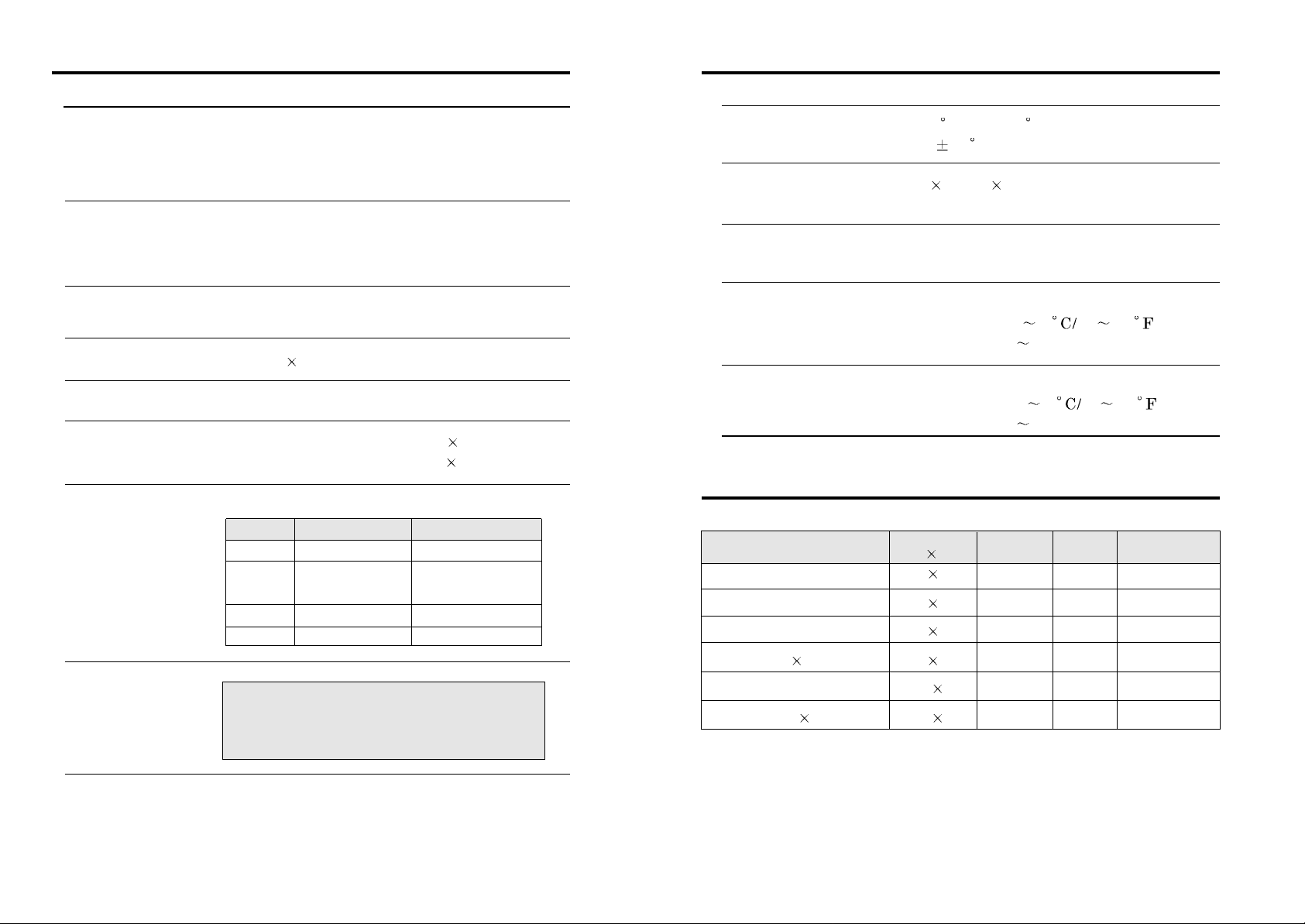
VGA 720 400 31.5 70 Non-interlaced
VGA 640 480 31.5 60 Non-interlaced
VESA 46K 800 600 46.9 75 Non-interlaced
VESA 800 600@85Hz 800 600 53.7 85 Non-interlaced
VESA 60K 1024 768 60.0 75 Non-interlaced
VESA 1024 768@85Hz 1024 768 68.7 85 Non-interlaced
Mode H.Freq (KHz) V.Freq(Hz) Remark
10
SPECIFICATIONS
Picture Tube Type : 15-inch, Flat Square Tube type
(14-inch, viewing area)
Dot Pitch : 0.28mm, MPR II
Face Treatment : Non-glare / Anti-static
Video Input Signal : R.G.B. Analog
Amp. Bandwidth : 85 MHz
Input Sync : TTL, separate negative / positive
Scan Frequency Horizontal : 30 - 69 KHz
Vertical : 50 - 120 Hz
Max. Resolution 1280 dots
1024 lines (at 60 Hz)
Power Source Free Voltage (100-240 Vac, 50/60 Hz)
Display Area Standard Display Area : 264mm(H) 198mm(V)
Full Screen Size : 284mm(H) 212mm(V)
Power Consumption Max. 80W
Regulatory Approvals
State Recovery Time Power LED
On None Green
Stand-by Green:0.5 second
Suspend Amber:0.5 second
3seconds
Sleep - Amber
Off - Off
Safety : UL, CSA, DHHS
EMI : FCC-B
11
Tilt/Swivel Range Tilt : 5 forward, 10 backward
Swivel : 45 leftward, rightward
Dimension 368(W) 394(D) 382(H) mm
(set with stand)
Weight(net/gross) 12.5 / 14.2 Kg
27.6 / 31.4 lbs
Operating Environment
Temperature : 10 40 50 104
Relative Humidity : 8 80%
Storage Environment
Temperature : -20 45 -4 113
Relative Humidity : 5 90%
FACTORY PRESET TIMINGS
Resolution
(dots lines)
This monitor has stored above-mentioned six timings in factory. You can save up
to 8 modes in the user memory automatically. Please note that if you save to user
memory over eight times, the first mode saved will be replaced with your ninth
mode.
Page 10
12
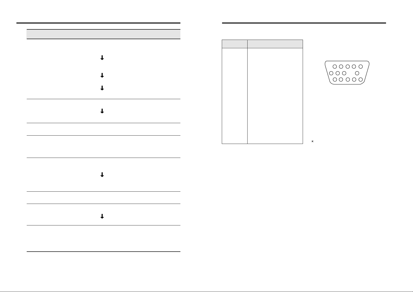
TROUBLESHOOTING
Check
Check if POWER SWITCH and COMPUTER
POWER SWITCH are in the on position.
Check if the signal cable is correctly connected to
the video card.
Check if the pins of D-sub connector are not bent.
Check if the computer is in the power saving mode.
Check if POWER SWITCH is in the on position.
Check if the power cord is correctly connected.
Check if the signal cable is suitable to the video card.
Adjust H & V SIZE or H & V POSITION to get the
proper image.
Keep the devices that may cause electrical
interference away from the monitor.
See the FCC information at the front cover of the
manual.
Operate DEGAUSS once.
Adjust CONTRAST and BRIGHTNESS.
Operate DEGAUSS once.
Adjust PINCUSHION/TRAPEZOID.
Symptom
No picture.
POWER LED is not
lit.
Image is unstable.
Image is not
centered, too small
or too large.
Picture bounces or a
wave pattern is
present in the
picture.
Color looks blotchy.
Picture is blurred.
Edges of available
area on the screen
are not straight.
13
DESCRIPTION FOR D-SUB CONNECTOR
1
2
3
4
5
6
7
8
9
10
11
12
13
14
15
Red
Green
Blue
GND
GND(Self-Test)
GND-Red
GND-Green
GND-Blue
No Pin
GND-H.Sync
GND-V.Sync
Bi-directional Data(SDA)
Horizontal Sync
Vertical Sync(VCLK)
Data Clock(SCL)
1
6
15
10
GND=Ground
Pin Signal
 Loading...