


CAT-250
Repeater Controller
Computer Automation Technology, Inc
7378 W. Atlantic Blvd. #239
Margate, Florida 33063
Phone: (954) 978-6171 Fax: (561) 488-2894
Internet: http://www.catauto.com

Table of Contents
Chapter 1
Introduction and Specifications
Introduction
1-1
Specifications
1-2
Chapter 2
System Configurations
Repeater – Transceiver
2-1
Repeater – RLS-1000 Diagram (Three Transceivers)
2-2
Repeater – Transceiver – WX-250 Weather Receiver
2-3
Repeater – WX-250 Weather Receiver Diagram
2-4
Repeater – Repeater (Two CAT-250 Controllers)
2-5
Dipswitch Settings
2-6
Chapter 3
Repeater Control by DTMF Commands
Interrogation of Repeater Control Status
3-1
Changing Repeater Control Status
3-1
Zone Control Tables 1 through 4
3-2
Zone Control Tables 4 through 8
3-3
Zone 1 DTMF Control Definitions
3-4
Zone 2 DTMF Control Definitions
3-5
Zone 3 DTMF Control Definitions
3-6
Zone 4 DTMF Control Definitions
3-7
Zone 5 DTMF Control Definitions
3-8
Zone 6 DTMF Control Definitions
3-9
Zone 7 DTMF Control Definitions
3-9
Zone 8 DTMF Control Definitions
3-10
Chapter 4
Repeater Operation Features
Time-of-Day Message
4-1
DTMF Keypad Test
4-1
DTMF Access
4-1
Forced DTMF Entry
4-1
DTMF Muting Override
4-1
Repeater ID (AT Rest)
4-1
Repeater ID (Active)
4-1
Macro Execute
4-2
Link Disconnect
4-2
Link Connect
4-2
Link Receive Only
4-2
Voice Message Selection
4-2
Chapter 5
Repeater Programming by DTMF Commands
Initialization
5-1
Programming the Master Unlock Number
5-1
Unlocking the Controller By Radio
5-1
Locking the Controller By Radio
5-1
Internal Command Assignment Table
5-2
Program Scheduler Event Macros
5-4
Program User Macros
5-4

Event Macro Command Table
5-5
Program Event Macros
5-6
Event Macro Default Table
5-6
Set Clock
5-8
Program Forced Entry Command
5-8
Program Voice Messages
5-8
Voice Message Table
5-9
Program CW Identification
5-10
CW ID Message Table
5-10
Program Control Codes and Prefix Numbers
5-10
Program Timer Memory
5-12
Send Audio Test Tone
5-14
Program Courtesy Tones
5-14
Courtesy Tone Programming Table
5-14
Exit Programming Mode
5-15
DTMF Programming Command Table
5-16
Chapter 6
Interfacing to Other Equipment
Determining COR Logic
6-1
Connection to Repeater’s Receiver
6-1
Connecting to Repeater’s Transmitter
6-1
Connecting to CTCSS Decoder
6-1
Interface Review
6-1
Connector Kit
6-2
Power Supply
6-2
Audio De-emphasis
6-2
Audio Level Adjustment
6-2
Printed Circuit Board Layout
6-2
Connector Assignment Table (J2)
6-3
Connector Assignment Table (J1)
6-4
TS-64 CTCSS Wiring Diagram
6-4
Chapter 7.
RS-232 Computer Interface
ISP Loader For CAT-250 Firmware
7-1
ED-250 Windows Editor
7-2
Activation of RS-232 Port With Dipswitch #8
7-2
Activation of RS-232 Port By Radio
7-2
Chapter 8.
Vocabulary Word List Table
8-1
Chapter 9.
Drawings (PC Board Artwork)
9-1
Chapter 10.
Schematics (Four Sheets)
10-1
Chapter 11.
Parts List Table
11-1
REVISED 04/18/16 (V1.08)

1-1
Chapter 1 - Introduction and Specifications
Congratulations on your purchase of the CAT-250 Repeater Controller. Programming the CAT-250 is a
snap, with its carefully structured uniform programming commands. The manual is easy to follow and
the voice synthesizer interacts with you during control and programming operation. An optional
WINDOW EDITOR is available to program the CAT-250 controller.
Voice Synthesizer
A vocabulary base of 290 words is available to ID your repeater and make voice announcements.
CW ID
The controller will switch to CW when a repeater user talks over the voice ID. Or ID in CW only,
depending on how the CAT-250 is configured.
Digital Voice Clock
The digital voice clock will announce the time upon request, during repeater IDs, or on the hour
through the grandfather clock feature. Back-up power for the clock is supplied by a .47 Farad
capacitor. Once 12VDC is supplied to the CAT-250 three hours are required for the capacitor to reach
full charge. During power failure the capacitor will power the clock for approximately six hours.
Scheduler
An advanced [20] position scheduler fully automates repeater operation. Any command that can be
manually executed can also be scheduled to one-minute accuracy. Program the hours, minutes, day of
week, or day of month and month of year. The CAT-250 will do the rest.
Courtesy Tone
Separate courtesy tones denote repeater and link activity. Create up to eight custom courtesy tones
and assign their use by executing event macro 13 Port #1 input and macro 14 for Port #2 input.
Port Configuration
The CAT-250 is a dual port controller. Port #1 is a repeater port. Port #2 can be configured as a
simplex transceiver or duplex transceiver port.
User Function Output Switches
Six open DRAIN user function output switches control equipment at your repeater site. These switches
are controlled manually by DTMF commands or from within a macro. They can be made to turn OFF,
ON or momentarily change state.
User Function Inputs
Four inputs activated by a voltage change from other equipment at the repeater site, causes the CAT250 to activate a macro. Two macros are assigned to each logic input. Different macros are called when
the input goes high and low.
DTMF Keypad Test
A DTMF keypad test will read back the numbers decoded in a synthesized voice. This feature is
available on both ports one and two.

1-2
Microprocessor
P89C668
Memory
25C640 (64K)
Voice Synthesizer
Texas Instruments MSP53C391NI2D
Voice Vocabulary
290 Words
DTMF Receivers
(2) MT8870
Operating Temperature
-15 to +55 degrees C
Call Letter ID
(4) Buffer size VOICE (15) - CW (16)
User Function Outputs
(6) Switch 40VDC @ 50mA.
Logic Inputs
(4) 10K ohm input impedance
Low (0 to 0.8VDC) High (2.4 to 15VDC)
Logic Outputs
Open Collector Relay Driver (28VDC at 50mA)
Audio Input
Receiver 0.2 - 2VAC adjustable 10K ohms
Audio Output
Transmitter 2VAC adjustable 600 ohms
Power
+9 to +15VDC at 80mA
Size
4.5" X 7.0"
Warranty
Limited one year, parts and labor.
User Macros
The CAT-250 supports forty User Macros each containing sixteen commands. A user macro is a series
of commands, defined by the repeater owner. Macros permit the owner to customize certain aspects of
repeater operation. Once the CAT-250 decodes the macro number, the commands will execute in the
order they were stored within the macro.
Event Triggered Macros
An event macro is a series of commands, defined by the repeater owner. Event Macros are positioned
throughout the program to execute during certain prescribed operations. The CAT-250 supports fifty
event macros each containing sixteen commands.
Specifications
FCC Part 15 RF Interference
When installed in the RM-250 rack mount enclosure, the CAT-250 has been tested and found to meet
the standards for a Class A digital device, as specified in Part 15 of the FCC Rules. These specifications
are designed to provide reasonable protection against such interference in a commercial installation.
However, there is no guarantee that interference will not occur in a particular installation.

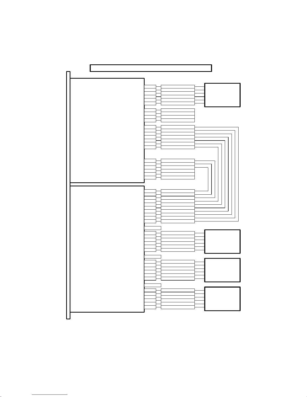
2-1
CAT-250
CAT-250 REPEATER AND TRANSCEIVER CONFIGURATION
J2-6
J2-4
J2-25
J2-10
J2-11
J2-13
J2-1
COR #1
CTCSS #1
PTT #1
TX AUDIO #1
RX AUDIO #1
GROUND
USER INPUT #3
USER INPUT #4
USER INPUT #1
USER INPUT #2
J2-22
J2-21
J2-2
J2-15
J2-14
USER OUTPUT #3
USER OUTPUT #2
USER OUTPUT #1
J2-19
J2-20 USER OUTPUT #4
J2-17
J2-16
GROUND
+12VDC OUTPUT
J1-1
J1-4
J1-3
J1-2
COR #2
TX AUDIO #2
PTT #2
CTCSS #2
RX AUDIO #2J1-5
J2-8 USER OUTPUT #6
GROUNDJ1-8
REPEATER
TRANSCEIVER
J2-7 USER OUTPUT #5
Chapter 2 - System Configuration
Repeater and Transceiver
In this configuration the CAT-250 supports a repeater on port #1 and a transceiver on port #2. Figure
2-1 shows the repeater connected to J2 the “25 Pin D” connector while the transceiver is connected to
J1 the “9 Pin D” connector. The transceiver port is also available on the “25 Pin D” connector to be
compatible with other CAT controllers.
Figure 2-1
2-2
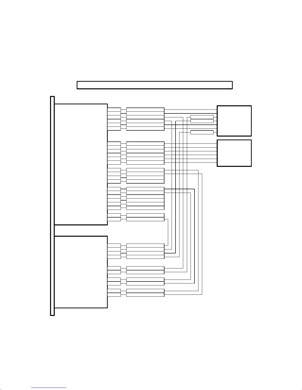
CAT-250
RLS-1000B
J2-6
J2-4
J2-25
J2-10
J2-11
J2-13
J2-1
J2-22
J2-21
J2-2
J1-1
J1-4
J1-8
J1-9
J1-3
J1-2
COR #2
GROUND
+12VDC OUTPUT
TX AUDIO #2
PTT #2
CTCSS #2
J4-15
J4-14
J4-17
J4-22
J4-18
J4-13
J4-2
J4-1
J4-16
PORT #3 CONTROL
REPEATER COR
CTCSS OUT
REPEATER PTT
RX AUDIO
+12VDC INPUT
GROUND
PORT #1 CONTROL
PORT #2 CONTROL
COR #1
CTCSS #1
PTT #1
TX AUDIO #1
RX AUDIO #1
GROUND
USER INPUT #3
USER INPUT #4
USER INPUT #1
USER INPUT #2
REPEATER
CAT-250 - RLS-1000 THREE TRANSCEIVERS
J2-15
J2-14
J2-20
USER OUTPUT #3
USER OUTPUT #2
USER OUTPUT #1
USER OUTPUT #4
J2-19
J2-8 USER OUTPUT #6
USER OUTPUT #5J2-7
RX AUDIO #2J1-5
2
3
5
1
7
4
1
2
3
4
5
7
1
7
4
2
5
3
COR
CTCSS
PTT
TX AUDIO
RX AUDIO
GROUND
COR
CTCSS
PTT
TX AUDIO
RX AUDIO
GROUND
COR
TX AUDIO
RX AUDIO
GROUND
PTT
CTCSS
TRANSCEIVER
TRANSCEIVER
TRANSCEIVER
TX AUDIOJ4-11
PORT #3
PORT #2
PORT #1
Repeater and Transceivers
In this configuration the CAT-250 supports a repeater and three transceivers. With an RLS-1000B
Remote Link Switch board connected to port #2 three transceiver can be added to the repeater system.
Three of the CAT-250’s user function switches are assigned to control the RLS-1000B’s transceiver
inputs.
Figure 2-2
2-3
CAT-250
J2-6
J2-4
J2-25
J2-10
J2-11
J2-13
COR #1
CTCSS #1
PTT #1
TX AUDIO #1
RX AUDIO #1
GROUND
J2-16
J2-17
+12VDC OUTPUT
GROUND
J2-1
USER INPUT #3
USER INPUT #4
USER INPUT #1
USER INPUT #2
J2-22
J2-21
J2-2
J1-1
J1-4
J1-3
J1-2
COR #2
TX AUDIO #2
PTT #2
CTCSS #2
RX AUDIO #2J1-5
J2-15
J2-14
USER OUTPUT #3
USER OUTPUT #2
USER OUTPUT #1
J2-19
J2-20 USER OUTPUT #4
REPEATER
TRANSCEIVER
J1-8 GROUND
WX-250
PTT OUTPUT
PTT INPUT
J4-3
J4-2
J4-11
J4-10
TX AUDIO OUTPUT
TX AUDIO INPUT
J4-4 WX ALERT DISABLE
WX ALERT ENABLEJ4-9
J4-1 PTT GROUND
J4-7
J4-6
WX ALERT START
WX ALERT STOP
J4-8 GROUND
J2-8 USER OUTPUT #6
CAT-250 - WX-250 WITH REMOTE BASE CONFIGURATION
USER OUTPUT #5J2-7
GROUND
TX AUDIO
PTT
Repeater With One Transceiver And Weather Receiver
In this configuration the CAT-250 supports a repeater, transceiver and weather receiver. The WX250 weather receiver mounts on the same 19-inch rack panel as the CAT-250. PTT and transmit
audio from the CAT-250 are connected to the repeater's transmitter through the normally closed
contacts of the double pole double throw relay located inside the WX-250. When a weather alert is
received, the relay will switch the weather alert audio to the TX audio input and provide a PTT signal to
key the transmitter.
Figure 2-3

2-4
CAT-250
J2-6
J2-4
J2-25
J2-10
J2-11
J2-13
COR #1
CTCSS #1
PTT #1
TX AUDIO #1
RX AUDIO #1
GROUND
WX-250
J2-16
J2-17
+12VDC OUTPUT
GROUND
REPEATER
PTT OUTPUT
PTT INPUT
J4-3
J4-2
J4-11
J4-10
TX AUDIO OUTPUT
TX AUDIO INPUT
J4-4 WX ALERT DISABLE
WX ALERT ENABLEJ4-9
J4-1 PTT GROUND
J4-7
J4-6
WX ALERT START
WX ALERT STOP
J4-8 GROUND
J2-8 USER OUTPUT #6
CAT-250 - WX-250 AUXILIARY RECEIVER CONFIGURATION
J1-1
J1-4
J1-3
J1-2
COR #2
TX AUDIO #2
PTT #2
CTCSS #2
RX AUDIO #2J1-5
J1-9 +12VDC OUTPUT
J2-1
USER INPUT #3
USER INPUT #4
USER INPUT #1
USER INPUT #2
J2-22
J2-21
J2-2
J2-15
J2-14
USER OUTPUT #3
USER OUTPUT #2
USER OUTPUT #1
J2-19
J2-20 USER OUTPUT #4
USER OUTPUT #5J2-7
Repeater And Weather Receiver
In this configuration the CAT-250 supports a repeater and weather receiver. The WX-250 is
connected to the transceiver port of the CAT-250. When a weather alert is received, a relay inside the
WX-250 will switch the weather alert audio to the RX2 audio input of the CAT-250 and provide a COR
input signal to activate the repeater’s transmitter.
Figure 2-4

2-5
CAT-250
CAT-250
CAT-250 TWO REPEATER CONFIGURATION
J2-6
J2-4
J2-25
J2-10
J2-11
J2-13
J2-1
COR #1
CTCSS #1
PTT #1
TX AUDIO #1
RX AUDIO #1
GROUND
USER INPUT #3
USER INPUT #4
USER INPUT #1
USER INPUT #2
J2-22
J2-21
J2-2
J2-15
J2-14
USER OUTPUT #3
USER OUTPUT #2
USER OUTPUT #1
J2-19
J2-20 USER OUTPUT #4
J2-6
J2-4
J2-25
J2-10
J2-11
J2-13
J2-1
COR #1
CTCSS #1
PTT #1
TX AUDIO #1
RX AUDIO #1
GROUND
USER INPUT #3
USER INPUT #4
USER INPUT #1
USER INPUT #2
J2-22
J2-21
J2-2
J2-15
J2-14
USER OUTPUT #3
USER OUTPUT #2
USER OUTPUT #1
J2-19
J2-20 USER OUTPUT #4
J1-1
J1-4
J2-17
J2-16
J1-3
J1-2
COR #2
GROUND
+12VDC OUTPUT
TX AUDIO #2
PTT #2
CTCSS #2
RX AUDIO #2J1-5
REPEATER #1
REPEATER #2
J1-1
J1-4
J2-17
J2-16
J1-3
J1-2
COR #2
GROUND
+12VDC OUTPUT
TX AUDIO #2
PTT #2
CTCSS #2
RX AUDIO #2J1-5
J2-8 USER OUTPUT #6
J2-8 USER OUTPUT #6
J2-7 USER OUTPUT #5
J1-8 GROUND
GROUNDJ1-8
USER OUTPUT #5J2-7
Dual Repeater
In this configuration two CAT-250 controllers have their link ports cross-coupled. By connecting PTT
#2 of one CAT-250 to the COR #2 of the other CAT-250 and TX2 audio of one controller connected
to the RX2 audio of the other controller the two repeaters can be linked together. When port #2 is
turned off each repeater will stand-alone.
Figure 2-5

2-6
Dip Switch
An eight-position dipswitch configures various functions of the CAT-250.
Switch 1 This switch determines Repeater COR input logic. Switch #1 should be ON if the repeater
receiver's COR is an active low and OFF if COR is active high.
Switch 2 This switch determines Repeater CTCSS input logic. Switch #2 should be ON if the
repeater receiver's CTCSS is an active low and OFF if CTCSS is active high.
Switch 3 This switch determines Link COR input logic. This switch should be ON if the link receiver's
COR is an active low and OFF if COR is active high.
Switch 4 This switch determines Link CTCSS input logic. Switch #4 should be ON if the link
receiver's CTCSS is an active low and OFF if CTCSS is active high.
Switch 5 This switch determines the operation of Port #2. Switch #5 should be ON for duplex
transceiver operation and OFF for simplex transceiver operation.
Switch 6 This switch places the CAT-250 in the cross band repeat mode. With transceivers on both
Port #1 and Port #2, enabled the link with the [5001] command. A signal received by the Port #1
receiver will only key the Port #2 transmitter and a signal received by the Port #2 receiver will only key
the Port #1 transmitter.
Switch 7 This switch is used to initialize the CAT-250. Set this switch to ON. Cycle the power OFF
and back ON. During power-up, the memory will be flushed and reloaded with default values. The
voice will say: "RESET SYSTEM OK." Set dipswitch #7 to the OFF position.
Switch 8 This switch is used to program a new MASTER un-lock number. Set switch #8 to ON. The
voice will say: "ENTER CONTROL." After the seven-digit master unlock number is entered, set switch
#8 to OFF. This switch is also used to activate the RS-232 port. Turn the power off set dipswitch #8 to
on and apply power to the CAT-250.

3-1
Zone (2)
Control Operator Code Read Channel Status (0)
Key-up and send: 100 2 0
Zone (1 through 4)
Control Operator Code Channel (1 through 8)
Activity (0=OFF 1=ON)
Key-up and send: 100 2 1 1
Chapter 3 - Repeater Control
The CAT-250 has eight control zones. These control zones can be manually controlled by DTMF
commands on the repeater input or by user and event macros.
Interrogation of Repeater Control Status
Key-up and send the control operator code [100] followed by the zone number and a zero. Un-key and
the voice will read back the channels that are turned on in that zone. Example: Read Zone 2 channel
status. If all the channels are turned off, the voice will say: "CLEAR."
Un-key and the voice will say: "ONE FOUR EIGHT"
Changing Repeater Control Status
To change the status of a channel, key-up and send the control operator code [100] followed by the
zone number, channel number and a [1] to turn the channel ON or a [0] to turn the channel OFF. Unkey and the voice will read back the zone, channel number and control activity. The voice will say:
"ONE ONE ON." or "THREE FIVE OFF."
Example: With a control operator prefix of 100, turn Zone 2 Channel 1 ON.
Un-key and the voice will say: "TWO ONE ON."
Control of the CAT-250 is also available through the Port #2 receiver. The procedure is the same as
above except the default control operator code for Port #2 is [200].

3-2
1
PORT #1 TRANSMIT
ENABLE*
2
PORT #1 COR AND CTCSS
ENABLE
3
PORT #1 COR OR CTCSS
ENABLE
4
PORT #1 TURN ON DELAY
ENABLE
5
PORT #1 DTMF PAD TEST
ENABLE*
6
PORT #1 COURTESY TONE
ENABLE*
7
PORT #1 DTMF MUTING
ENABLE
8
PORT #1 TIMEOUT
ENABLE*
1
PORT #2 TRANSMIT
ENABLE*
2
PORT #2 COR AND CTCSS
ENABLE
3
PORT #2 COR OR CTCSS
ENABLE
4
PORT #2 TURN ON DELAY
ENABLE
5
PORT #2 DTMF PAD TEST
ENABLE*
6
PORT #2 AUTO-DISCONNECT
ENABLE
7
PORT #2 DTMF MUTING
ENABLE
8
PORT #2 TIMEOUT
ENABLE*
1
PORT #2 CONTROL OPERATOR
ENABLE*
2
PORT #2 MACRO CONTROL
ENABLE*
3
RESERVED
ENABLE
4
RESERVED
ENABLE
5
RESERVED
ENABLE
6
RESERVED
ENABLE
7
RESERVED
ENABLE
8
RESERVED
ENABLE
1
USER LOGIC INPUT #1
ENABLE*
2
USER LOGIC INPUT #2
ENABLE*
3
USER LOGIC INPUT #3
ENABLE*
4
USER LOGIC INPUT #4
ENABLE*
5
SCHEDULER
ENABLE*
6
TIME OF DAY REQUEST
ENABLE*
7
GRANDFATHER CLOCK
ENABLE*
8
GRANDFATHER CLOCK SLEEP
ENABLE
Repeater Control Channels
Zone 1
Zone 2
Zone 3
Zone 4

3-3
1
USER OUTPUT SWITCH #1
ENABLE
2
USER OUTPUT SWITCH #2
ENABLE
3
USER OUTPUT SWITCH #3
ENABLE
4
USER OUTPUT SWITCH #4
ENABLE
5
USER OUTPUT SWITCH #5
ENABLE
6
USER OUTPUT SWITCH #6
ENABLE
7
DTMF ACCESS
ENABLE
8
FORCED DTMF ENTRY
ENABLE*
1
REPEATER ID #1 (At Rest)
ENABLE*
2
REPEATER ID #2 (Active)
ENABLE*
3
SQUELCH TAIL MESSAGE
ENABLE
4
TRANSMITTER DROP MESSAGE
ENABLE
5
TIMED MESSAGE #1
ENABLE
6
TIMED MESSAGE #2
ENABLE
7
RESERVED
ENABLE
8
RESERVED
ENABLE
1
FAN CONTROL
ENABLE
2
CTCSS ENCODER LOGIC
ENABLE
3
ECHOLINK® CONTROL
ENABLE
4
TRANSMITTER HANG TIME
ENABLE*
5
RESERVED
ENABLE
6
RESERVED
ENABLE
7
RESERVED
ENABLE
8
RESERVED
ENABLE
1
RESERVED
ENABLE
2
RESERVED
ENABLE
3
RESERVED
ENABLE
4
RESERVED
ENABLE
5
RESERVED
ENABLE
6
RESERVED
ENABLE
7
RESERVED
ENABLE
8
RESERVED
ENABLE
Zone 5
Zone 6
Zone 7
Zone 8
* During initialization these control channels are set to the enable position.

3-4
Zone 1 - Repeater Control Channels
1. Port #1 Transmitter Enable
This is the master repeater switch. This channel must be enabled for normal repeater operation. The
CAT-250 will continue to respond to control operator commands even when the Port #1 transmitter is
disabled. This channel will automatically be enabled after a dipswitch #7 initialization reset.
2. Port #1 COR and CTCSS Enable
When this channel is enabled, in addition to a COR input, an input from a CTCSS decoder at J2-4 must
also be present before Port #1 will activate. A COR input by itself will have no affect. To prevent loss of
control, DO NOT ENABLE THIS CHANNEL unless a CTCSS decoder is connected to J2-4.
3. Port #1 COR or CTCSS Enable
When this channel is enabled, the COR and CTCSS inputs will function as a (OR) logic input. This
means activity on either the COR or CTCSS inputs will cause the controller to key the Port #1
transmitter.
4. Port #1 Turn on Delay Enable
When this channel is enabled, a deliberate and sustained input on Port #1 must be present before the
controller will respond. A time delay of 0.1 to 9.9 seconds can be selected with the [*624*]
programming command. When the CAT-250 is initialized, this timer defaults to 1.0 seconds. This
channel is useful during periods when noise bursts are present on the repeater input.
5. Port #1 DTMF Pad Test Enable
When this channel is enabled, a repeater user is able to perform a test of their radio's 12 or 16-button
keypad through the repeater port. As the numbers are being decoded, they are stored in memory.
When the repeater user stops transmitting the controller will read back all the numbers that were
decoded. The Forced DTMF Entry key is defaulted to the [D] key. It must be entered last and it will
not read back during the pad test.
6. Port #1 Courtesy Tone Enable
When this channel is enabled, a courtesy tone will occur when the COR signal is lost. To eliminate the
courtesy tone, turn this channel OFF. The timeout timer will continue to be reset.
7. Port #1 DTMF Muting Enable
When this channel is enabled, anytime a DTMF tone is received, the audio will be turned off to the Port
#1 transmitter. The transmit audio will remain muted until a pre-determined time after the last DTMF
tone is received. During the mute period, cover beeps are transmitted each second to indicate repeater
activity. This feature prevents control commands from being repeated. It provides an extra measure
of security. There may be times when it is desirable to pass the DTMF tones through the repeater. To
temporarily disable DTMF muting, precede the DTMF string with a (#).

3-5
Zone 2 - Link Control Channels
8. Port #1 Timeout Enable
Port #1 time-out is user programmable with the [*601*] timer programming commands. When the
CAT-250 is initialized, this timer defaults to 3 minutes. When this channel is turned off, the repeater,
port #1 will not timeout.
1. Port #2 Transmitter Enable
This channel must be enabled for link operation. This channel will automatically be enabled after a
dipswitch #7 initialization reset.
2. Port #2 COR and CTCSS Enable
When this channel is enabled, in addition to a COR input at J2-5, an input from a CTCSS decoder at J23 must also be present before the repeater will activate. A COR input by itself will have no affect.
3. Port #2 COR or CTCSS Enable
When this channel is enabled, the COR and CTCSS inputs will function as a (OR) logic input. This
means activity on either the COR or CTCSS inputs will cause the controller to key the repeater's
transmitter.
4. Port #2 Turn on Delay Enable
When this channel is enabled, a deliberate and sustained input on Port #2 must be present before the
controller will activate the repeater. A time delay of 0.1 to 9.9 seconds can be selected with the
[*624*] programming command. When the CAT-250 is initialized, this timer defaults to 1.0 seconds.
This channel is useful during periods when noise bursts are present on the transceiver input.
5. Port #2 DTMF Pad Test Enable
When this channel is enabled, a repeater user is able to perform a test of their radio's 12 or 16-button
keypad through Port #2. As the numbers are being decoded, they are stored in memory. When the
repeater user stops transmitting the controller will read back all the numbers that were decoded. The
Forced DTMF Entry key is defaulted to the [D] key. It must be entered last and it will not read back
during the pad test.
6. Port #2 Auto Disconnect Enable
When this channel is enabled, the link will disconnect automatically after a period of repeater inactivity.
The voice will say: “LINK TIME OUT”. A repeater or transceiver COR will keep the link activate until
the repeater returns to rest. A rest period of up to 29 minutes can be selected with the [*607*]
programming command. When the CAT-250 is initialized, this timer defaults to 10 minutes.

3-6
Zone 3 - Link Control Channels
7. Port #2 DTMF Muting Enable
When this channel is enabled, anytime a DTMF tone is received, the audio will be turned off to the Port
#2 transmitter. The transmit audio will remain muted until a pre-determined time after the last DTMF
tone is received. During the mute period, cover beeps are transmitted each second to indicate repeater
activity. This feature prevents control commands from being repeated. It provides an extra measure
of security. There may be times when it is desirable to pass the DTMF tones through the repeater. To
temporarily disable DTMF muting, precede the DTMF string with a (#).
8. Port #2 Timeout Enable
Link time-out is user programmable with the [*602*] timer programming commands. When the CAT250 is initialized, this timer defaults to 3 minutes. When this channel is turned off, the repeater link
port, will not timeout.
1. Port #2 Control Operator Enable
When this channel is enabled, the CAT-250 will accept control operator commands to change the
settings of the zone channels from the link side. The default code is [200]. This code can be changed
with the [*502*] programming command.
2. Port #2 Macro Enable
When this channel is enabled, the CAT-250 will accept user macro commands from the link side.
3. Reserved
4. Reserved
5. Reserved
6. Reserved
7. Reserved
8. Reserved

3-7
Zone 4 - Miscellaneous Control Channels
1. User Logic Input #1 Enable
When this channel is enabled, an active high logic input on connector J2-1 will execute event macro #5
while an active low logic input will execute event macro #6.
2. User Logic Input #2 Enable
When this channel is enabled, an active high logic input on connector J2-2 will execute event macro #7
while an active low logic input will execute event macro #8.
3. User Logic Input #3 Enable
When this channel is enabled, an active high logic input on connector J2-21 will execute event macro
#9 while an active low logic input will execute event macro #10.
4. User Logic Input #4 Enable
When this channel is enabled, an active high logic input on connector J2-22 will execute event macro
#11 while an active low logic input will execute event macro #12.
5. Scheduler Enable
When this channel is enabled, all action by the scheduler will be executed per the times programmed in
the scheduler table. There may be times, during emergency net operations, when it is not desirable to
have channels change automatically. To suspend scheduler operation, turn this channel off.
6. Time of Day Request Enable
When this channel is enabled, repeater users can request a time of day announcement by entering the
time of day request number. This message will consist of up to 15 words selected from the voice
vocabulary table and is programmed with the [*3109*] command. When the CAT-250 is initialized,
this message defaults to: "THE TIME IS 7:15 PM."
7. Grandfather Clock Enable
When this channel is enabled, the CAT-250 will announce the time of day every hour on the hour. This
message will consist of up to 15 words selected from the voice synthesizer vocabulary table and
programmed with the [*3110*] command. When the CAT-250 is initialized, this message defaults to:
"CAT-250 REPEATER THE TIME IS 7:15 PM."
8. Grandfather Clock Sleep Mode Enable
It may be desirable to suspend the grandfather clock operation during the early morning hours. When
this channel is enabled, the last announcement will be at 11:00 PM. Time announcements will resume
at 7:00 AM the next morning.

3-8
Zone 5 - Miscellaneous Control Channels
1. USER Output Switch #1 Enable
When this channel is enabled, switch #1 is turned on. Connector J2 pin 14 will sink 50 MA to ground.
2. USER Output Switch #2 Enable
When this channel is enabled, switch #2 is turned on. Connector J2 pin 15 will sink 50 MA to ground.
3. USER Output Switch #3 Enable
When this channel is enabled, switch #3 is turned on. Connector J2 pin 19 will sink 50 MA to ground.
4. USER Output Switch #4 Enable
When this channel is enabled, switch #4 is turned on. Connector J2 pin 20 will sink 50 MA to ground.
5. USER Output Switch #5 Enable
When this channel is enabled, switch #3 is turned on. Connector J2 pin 7 will sink 50 MA to ground.
6. USER Output Switch #6 Enable
When this channel is enabled, switch #4 is turned on. Connector J2 pin 8 will sink 50 MA to ground.
7. DTMF Access Enable
When this channel is enabled, a DTMF Access number selected by programming command [*503*]
must be entered to activate Port #1. The repeater will continue to operate until a period of inactivity
occurs determined by the [*606*] sleep timer. Once the timer expires the next repeater user must reenter the DTMF Access number.
8. Forced DTMF Entry D Key
When this channel is enabled it is possible to force a DTMF command even while the port is active. To
force a DTMF command, end the command with a [D]. This key can be changed with the [*29x]
programming command.

3-9
Zone 6 – Voice Message Control Channels
Zone 7 - Miscellaneous Control Channels
1. Repeater ID #1 (At Rest) Enable
When this channel is enabled, repeater ID message #1 will repeat subject to the setting of the ID
timer. This ID will consist of up to 15 words selected from the voice vocabulary table and is
programmed with the [*3101] command.
2. Repeater ID #2 (Active) Enable
When this channel is enabled, the Repeater ID Message #2 will repeat subject to the setting of the ID
timer. This ID will consist of up to 15 words selected from the voice vocabulary table and is
programmed with the [*3102] command. When Repeater ID #1 and #2 are enabled, ID messages
selection will be determined by whether the repeater is at rest or a QSO is in progress.
3. Squelch Tail Message Enable
When this channel is enabled, the squelch tail message occurs when a repeater user un-keys their
transmitter. This message will repeat subject to the setting of the [*610*] squelch tail message timer.
This message will consist of up to 15 words selected from the vocabulary table and programmed with
the [*3103] command.
4. Transmitter Drop Out Message Enable
When this channel is enabled, the voice drop out message will occur just before the repeater
transmitter turns off. This message will repeat subject to the setting of the [*611*] drop out message
timer. This message will consist of up to 15 words selected from the voice vocabulary table and is
programmed with the [*3104] command.
5. Timed Message #1 Enabled
When this channel is enabled, the timed voice message will occur on a regular schedule subject to the
setting of the timed message timer. This message will consist of up to 15 words selected from the
voice vocabulary table and is programmed with the [*3105] command.
6. Timed Message #2 Enabled
When this channel is enabled, the timed voice message will occur on a regular schedule subject to the
setting of the timed message timer. This message will consist of up to 15 words selected from the
voice vocabulary table and is programmed with the [*3106] command.
7. Reserved
8. Reserved
1. Fan Control Enable
When this channel is enabled, user output switch #6 is converted into a Fan Control output. When PTT
#1 turns ON, user output #6 J2 pin 8 will turn ON. After PTT #1 turns OFF this output will remain ON
for an additional period of time determined by the [*612*] Fan Control timer. This timer default is 60
seconds. Use this output to control a fan relay to cool the repeater’s transmitter. When this channel is
enabled, Zone 5 Channel 6 will have no effect.

3-10
Zone 8 - Miscellaneous Control Channels
2. CTCSS Encoder Switch Enable
When this channel is enabled, user output switch #5 is converted into a CTCSS Encoder Switch output.
When Port #1 goes active, user output #5 J2 pin 7 will turn ON. After Port #1 goes inactive, this
output will remain ON for an additional period of time determined by the [*626*] CTCSS Encoder
timer. This timer default is 4.0 seconds. Use this output to control an external CTCSS encoder. When
this channel is enabled, Zone 5 Channel 5 will have no effect.
3. Echolink® Control Enable
When the Link is enabled and DTMF Muting (Zone 1 Channel 7) is enabled, a DTMF command entered
through Port #1 will be muted on both the Port #1 and Port #2 transmit audios. When this channel is
enabled, Port #2 transmit audio will be the actual DTMF command. The DTMF command will continue
to be muted on the Port #1 transmit audio.
4. Transmitter Hang Time Enable
When this channel is enabled, the transmitter will have a hang-time subject to the
settings of the COR Drop to Courtesy Beep Timer [*621*] and the Courtesy Beep to
PTT Drop Timer [*622*]. At default these timers are set for one second and four
seconds.
5. Reserved
6. Reserved
7. Reserved
8. Reserved
1. Reserved
2. Reserved
3. Reserved
4. Reserved
5. Reserved
6. Reserved
7. Reserved
8. Reserved

4-1
Chapter 4 - Repeater Operation
Time of Day Message
Key-up, and enter [400], the time of day access code. Un-key, and the voice synthesizer will announce
the time. Example: The voice will say: "THE TIME IS 7:30 PM". The time of day announcement is
stored in voice message [9] and can be changed with the [*3109] programming command.
DTMF Keypad Test Port #1 and Port #2
Key-up, and enter [375], the DTMF keypad access code followed by the keypad numbers and letters to
be tested. The entries can be in any order. Un-key, and the voice will read-back all numbers and
letters that were decoded including the "STAR" and "POUND". The Forced DTMF Entry key is defaulted
to the [D] key. It must be entered last and it will not read back during the pad test.
DTMF Access Port #1 and Port #2
When the CAT-250 is in the DTMF Access mode, you must enter the DTMF Access code to activate the
repeater. The voice will say: "OK UP" and the repeater will respond to a COR and or CTCSS input.
When the repeater returns to rest, for a time determined by the sleep timer, the DTMF Access code
must be re-entered to activate the repeater. You can bypass the rest period and return the repeater to
DTMF access mode by re-entering [325], the DTMF access code. The voice will say: "OK DOWN".
Forced DTMF Command Entry Port #1 and Port #2
During normal operation a DTMF command is entered when the port goes inactive. It is possible to
force a DTMF command entry even while the port is active. The CAT-250 will accept the [D] key as an
entry command. This key can be changed with the [*29X] programming command.
DTMF Muting Override Port #1 and Port #2
With DTMF muting enabled, there may be times when it is desirable to pass the DTMF tones to the
repeater or link transmitter. To temporarily disable DTMF muting, precede the DTMF string with a
pound [#].
Repeater ID #1 (At Rest)
If the repeater has been at rest for a period in excess of the ID timer setting, when the repeater is
keyed, the CAT-250 will send ID #1. This ID should be longer than ID #2 and include additional
information about the repeater or sponsoring organization. Example: "WITH ONE HUNDRED WATTS OF
RF POWER AT YOUR SERVICE THIS IS THE W4XYZ REPEATER SYSTEM -- GOOD AFTERNOON".
Repeater ID #2 (Active)
If a QSO is in progress and it's time to identify the repeater, the CAT-250 will wait until COR drops to
send ID #2. This ID should be short so as not to interfere with the QSO in progress. Example:
"W4XYZ REPEATER." This ID is also called as the final ID of the ten-minute period.

4-2
Key-up and enter: 7 0 0 0 7
Voice Message Number
Voice Prefix Number
Macro Execute
A macro is a series of commands, defined by the repeater owner. Macros permit the owner to
customize certain aspects of repeater operation. Once the CAT-250 decodes the macro number, the
commands will execute in the order they were stored within the macro string.
Link Disconnect
Key-up on the repeater or link input and enter the link disconnect control Macro #28 number [5000].
The CAT-250 will disconnect the link port from the repeater port, and the voice will say: “LINK OFF.”
See the Event Macro Data table in Chapter 5.
Link Connect
Key-up on the repeater or link input and enter the link connect control Macro #27 number [5001]. The
CAT-250 will connect the link port to the repeater port, and the voice will say: “LINK ON.” See the
Event Macro Data table in Chapter 5.
Link Receive Only
Key-up on the repeater's input and enter the link receive only control Macro #26 number [5002]. The
CAT-250 will connect the link port to the repeater port and the voice will say: “LINK RECEIVER ON.”
The link transmitter will be disabled. See the Event Macro Data table in Chapter 5.
Voice Message Selection
Key-up and enter the VOICE prefix followed by the message number. The CAT-250 will key the
transmitter and play the message stored at that location. Example: With a VOICE prefix number of
700, play message stored at table position seven.

5-1
Chapter 5 - Repeater Programming By DTMF Tone
This section describes how the repeater owner using a DTMF keypad programs the CAT-250 controller.
The various types of program commands are described in detail and examples are given in the
following text.
Initialization
To initialize the CAT-250, set dipswitch #7 to on and cycle DC power. During power-up, the voice will
say: "RESET SYSTEM OK." Set dipswitch #7 to off. Initialization consists of the following operations:
Dipswitch #7 Initialization
1. All memory locations are cleared.
2. The control channels marked with a [*] are enabled.
3. The master unlock number is loaded with the default value [1234567].
4. The unlock number is loaded with the default value [7654321].
5. The Port #1 control operator prefix code is loaded with [100].
6. The Port #2 control operator prefix code is loaded with [200].
7. All codes are loaded with default values.
8. All timers are loaded with default values.
9. The two voice Ids are loaded with “CAT-250 REPEATER”.
10. All messages are loaded with default messages.
11. Event macros are loaded with defaults.
Programming the Master Unlock Number
To program the Master UNLOCK number, set dipswitch #8 to the on position. The voice will say:
"ENTER CONTROL." Key-up and enter a seven-digit number. Un-key, if the number is accepted, the
voice will say: "CONTROL OK." If the number is rejected, the voice will say: "ENTER CONTROL." Keyup and enter the seven-digit number. Set dipswitch #8 to the off position.
Unlocking the Controller By Radio From Port #1 and Port #2 [7654321]
To unlock the controller, key-up and enter the unlock number. The voice will say: "CAT 250
CONTROL."
Note: The CAT-250 can be unlocked and placed in the programming mode with either the unlock or
the master unlock number. The master unlock number must be changed by using dipswitch #8. The
unlock number can be changed remotely without having to go to the site. For security reasons use the
unlock number because it can easily be changed. Use the master unlock number when the conditions
are thought to be secure.
Locking the Controller By Radio [*0]
Key-up and send [*0]. Un-key, the controller will lockup and the voice will say: "CONTROL EXIT." The
controller will lock automatically when the programming timer expires. The voice will say: "TIMER
EXIT." The programming time limit is set by the programming timer [*605*]. The default time is ten
minutes.
NOTE: The CAT-250 must be unlocked to perform the following programming functions.

5-2
COMMAND
CHANNEL
ACTION
CONTROL REPEATER ZONE 1
11
1-8
0=OFF 1=ON
CONTROL REPEATER ZONE 2
12
1-8
0=OFF 1=ON
CONTROL REPEATER ZONE 3
13
1-8
0=OFF 1=ON
CONTROL REPEATER ZONE 4
14
1-8
0=OFF 1=ON
CONTROL REPEATER ZONE 5
15
1-8
0=OFF 1=ON
CONTROL REPEATER ZONE 6
16
1-8
0=OFF 1=ON
CONTROL REPEATER ZONE 7
17
1-8
0=OFF 1=ON
CONTROL REPEATER ZONE 8
18
1-8
0=OFF 1=ON
COMMAND
COMMENTS
PLAY TIME OF DAY
2000
PLAY DAY OF WEEK
2001
PLAY VOICE MESSAGE (No Interruption with COR)
30XX
01-20
PLAY VOICE MESSAGE (Interruption with COR)
31XX
01-20
PLAY VOICE MESSAGE (Interruption with COR, Switch to CW)
32XX
01-20
PLAY CW BUFFER
3300
PLAY CW CHARACTER
34XX
01-46
LOAD COURTESY TONE PORT #1
36XX
01-08
LOAD COURTESY TONE PORT #2
37XX
01-08
PLAY COURTESY TONE PORT #1
3800
PLAY COURTESY TONE PORT #2
3900
PULSE USER OUTPUT SWITCH #1 (PULSE RATE 100mSEC)
41XX
01-99
PULSE USER OUTPUT SWITCH #2 (PULSE RATE 100mSEC)
42XX
01-99
PULSE USER OUTPUT SWITCH #3 (PULSE RATE 100mSEC)
43XX
01-99
PULSE USER OUTPUT SWITCH #4 (PULSE RATE 100mSEC)
44XX
01-99
PULSE USER OUTPUT SWITCH #5 (PULSE RATE 100mSEC)
45XX
01-99
PULSE USER OUTPUT SWITCH #6 (PULSE RATE 100mSEC)
46XX
01-99
AUDIO SWITCH CONTROL [RX1 TO TX1]
500X
0=OFF 1=ON
AUDIO SWITCH CONTROL [RX1 TO TX2]
501X
0=OFF 1=ON
AUDIO SWITCH CONTROL [RX1 TO TX1 AND TX2]
502X
0=OFF 1=ON
AUDIO SWITCH CONTROL [RX2 TO TX1]
510X
0=OFF 1=ON
AUDIO SWITCH CONTROL [RX2 TO TX2]
511X
0=OFF 1=ON
AUDIO SWITCH CONTROL [RX2 TO TX1 AND TX2]
512X
0=OFF 1=ON
AUDIO SWITCH CONTROL [VOICE TO TX1]
520X
0=OFF 1=ON
AUDIO SWITCH CONTROL [VOICE TO TX2]
521X
0=OFF 1=ON
AUDIO SWITCH CONTROL [VOICE TO TX1 AND TX2]
522X
0=OFF 1=ON
AUDIO SWITCH CONTROL [BEEP OR CW TO TX1]
530X
0=OFF 1=ON
CAT-250 Internal Command Pointer Assignments

5-3
AUDIO SWITCH CONTROL [BEEP OR CW TO TX2]
531X
0=OFF 1=ON
AUDIO SWITCH CONTROL [BEEP OR CW TO TX1 AND TX2]
532X
0=OFF 1=ON
LOAD TIME DELAY (SECONDS)
60XX
01-99
PTT #1 CONTROL
611X
0=OFF 1=ON
PTT #2 CONTROL
612X
0=OFF 1=ON
PTT #1 AND PTT #2 CONTROL
613X
0=OFF 1=ON
PTT #1 WITH DELAY AND AUDIO SWITCH [VOICE TO TX1]
614X
0=OFF 1=ON
PTT #2 WITH DELAY AND AUDIO SWITCH [VOICE TO TX2]
615X
0=OFF 1=ON
PTT #1 WITH DELAY AND AUDIO SWITCH [VOICE TO TX1-TX2]
616X
0=OFF 1=ON
USER FUNCTION SWITCH #1 OUTPUT (PULSE 500mSEC)
621X
0=OFF 1=ON
2=PULSE
USER FUNCTION SWITCH #2 OUTPUT (PULSE 500mSEC)
622X
0=OFF 1=ON
2=PULSE
USER FUNCTION SWITCH #3 OUTPUT (PULSE 500mSEC)
623X
0=OFF 1=ON
2=PULSE
USER FUNCTION SWITCH #4 OUTPUT (PULSE 500mSEC)
624X
0=OFF 1=ON
2=PULSE
USER FUNCTION SWITCH #5 OUTPUT (PULSE 500mSEC)
625X
0=OFF 1=ON
2=PULSE
USER FUNCTION SWITCH #6 OUTPUT (PULSE 500mSEC)
626X
0=OFF 1=ON
2=PULSE
DISCONNECT PORT #2 FROM PORT #1
7000
CONNECT PORT #2 TO PORT #1
7001
CONNECT PORT #2 RECEIVER TO PORT #1
7002
DTMF ACCESS REPEATER
710X
0=OFF 1=ON
DISABLE EVENT MACRO
80XX
01-50
ENABLE EVENT MACRO
81XX
01-50
DISABLE USER MACRO
82XX
01-40
ENABLE USER MACRO
83XX
01-40
SEND VOICE WORD
9XXX
001-998
Figure 5-1
Scheduled Event Macro Time (30-49) Command Memory
Event Macros (30-49) are linked to the scheduler. The [*10XX], [*11XX] and [*12XX] programming
commands are used to read, program and erase the scheduled time the macros execute.
Read Scheduled Event Macro Time (30-49)
Key-up and send [*10XX]. Un-key and the voice will read back the status of the memory location. If
there is no command stored at that memory location, the voice will say: "All CLEAR." If a command is
stored at that memory location, the voice will read back the time, day, day of month and month of
year.

5-4
DAY OF WEEK SCHEDULER PROGRAMMING TABLE
0=Daily 2=Monday 4=Wednesday 6=Friday 8=Weekdays
1=Sunday 3=Tuesday 5=Thursday 7=Saturday 9=Weekends
Minutes Day of Week
Hour
*1144 ** 15 6
Minutes Day of Week
Hour Day of Month
Month of Year
*1130 09 00 6 00 00
Programming Command Separator
*14 03 1 * 123 * 1511 6141 9450 9695 6140
Macro Table Position Say:[POWER]
Macro Control (0=OFF 1=ON) Say:[HI]
Macro Executing Number
Turn User Switch #1 to ON
PTT#1 And Audio Switch ON PTT #1 And Audio Switch OFF
Program Scheduled Event Macro Time (30-49)
Key-up and send [*1130] followed by the hours, minutes, day of week, or day of month and month of
year. Un-key and the voice will say: "CONTROL OK." Example: 9:00 AM Every Friday.
Enable – Disable Scheduled Event Macro (30-49)
Key-up and send [*1130 1] to enable scheduler macro 30 or [*1130 0] to disable macro 30.
Example: Set Event Macro 44 for 15 minutes after every hour on Friday.
Erase Scheduled Event Macro Time (30-49)
Key-up and send [*12XX]. Un-key, the voice will say: "CONTROL OK."
User Macro Command Memory
Macros are used to store custom commands of up to sixteen operations that will execute with a single
DTMF entry.
Read User Macro Locations (01-40)
Key-up and send [*13XX]. Un-key and voice will read back the macro control number followed by the
enable control byte followed by the macro data commands stored at that memory location. If the
location is empty, the voice will say: "MACRO NUMBER XX NO CODE NO DATA."
Program User Macro Locations (01-40)
Key-up and send [*14XX] followed by the macro control number and the string of internal commands
to be executed. See Figure 5-1. Un-key and the voice will say: "CONTROL OK." Example: Program
macro #3 with a control number of [123] to Turn ON User Function Switch #1 and say: “HI POWER”.
The Macro Control number [123] is the number entered by a repeater user to execute the macro.

5-5
MACRO
DEFINITION
MACRO
DEFINITION
01
PORT #1 COR/CTCSS ACTIVE
26
PORT #2 RECEIVE ONLY
02
PORT #1 COR/CTCSS INACTIVE
27
PORT #2 CONNECT
03
PORT #2 COR/CTCSS ACTIVE
28
PORT #2 DISCONNECT
04
PORT #2 COR/CTCSS INACTIVE
29
PORT #2 AUTO DISCONNECT
05
LOGIC INPUT #1 ACTIVE HIGH
30
SCHEDULED EVENT MACRO #30
06
LOGIC INPUT #1 ACTIVE LOW
31
SCHEDULED EVENT MACRO #31
07
LOGIC INPUT #2 ACTIVE HIGH
32
SCHEDULED EVENT MACRO #32
08
LOGIC INPUT #2 ACTIVE LOW
33
SCHEDULED EVENT MACRO #33
09
LOGIC INPUT #3 ACTIVE HIGH
34
SCHEDULED EVENT MACRO #34
10
LOGIC INPUT #3 ACTIVE LOW
35
SCHEDULED EVENT MACRO #35
11
LOGIC INPUT #4 ACTIVE HIGH
36
SCHEDULED EVENT MACRO #36
12
LOGIC INPUT #4 ACTIVE LOW
37
SCHEDULED EVENT MACRO #37
13
PLAY COURTESY TONE #1
38
SCHEDULED EVENT MACRO #38
14
PLAY COURTESY TONE #2
39
SCHEDULED EVENT MACRO #39
15 40
SCHEDULED EVENT MACRO #40
16
SQUELCH TAIL MESSAGE
41
SCHEDULED EVENT MACRO #41
17
TRANSMITTER DROP MESSAGE
42
SCHEDULED EVENT MACRO #42
18
ID MESSAGE INITIAL
43
SCHEDULED EVENT MACRO #43
19
ID MESSAGE PENDING
44
SCHEDULED EVENT MACRO #44
20
ID MESSAGE FORCED
45
SCHEDULED EVENT MACRO #45
21
ID MESSAGE FINIAL
46
SCHEDULED EVENT MACRO #46
22
TIMED MESSAGE #1
47
SCHEDULED EVENT MACRO #47
23
TIMED MESSAGE #2
48
SCHEDULED EVENT MACRO #48
24
DTMF ACCESS UP
49
SCHEDULED EVENT MACRO #49
25
DTMF ACCESS DOWN
50
POWER UP
Program User Macro Locations (01-40)
Key-up and send [*14XX] followed by a [1] to enable the macro or a [0] to disable the macro. This
feature permits the macro to be turned off without having to erasing it. Un-key and voice will say:
“CONTROL OK.”
Erase User Macro Locations (01-40)
Key-up and send [*15XX]. Un-key, the voice will say: "CONTROL OK."
Event Macro Command Memory
Event Macros are used to perform custom operations at pre determined times during repeater
operation.

5-6
01
PORT #1 COR/CTCSS ACTIVE
02
PORT #1 COR/CTCSS INACTIVE
03
PORT #2 COR/CTCSS ACTIVE
04
PORT #2 COR/CTCSS INACTIVE
05
LOGIC INPUT #1 ACTIVE HIGH
1511
06
LOGIC INPUT #1 ACTIVE LOW
1510
07
LOGIC INPUT #2 ACTIVE HIGH
1521
08
LOGIC INPUT #2 ACTIVE LOW
1520
09
LOGIC INPUT #3 ACTIVE HIGH
1531
10
LOGIC INPUT #3 ACTIVE LOW
1530
11
LOGIC INPUT #4 ACTIVE HIGH
1541
12
LOGIC INPUT #4 ACTIVE LOW
1540
13
COURTESY TONE PORT #1 INPUT
5301
3800
5300
14
COURTESY TONE PORT #2 INPUT
5301
3421
5300
15
16
SQUELCH TAIL MESSAGE
5201
3003
5200
17
TRANSMITTER DROP MESSAGE
5201
3004
5200
18
ID MESSAGE INITIAL
6120
5201
3201
5220
19
ID MESSAGE PENDING
6120
5201
3202
5220
20
ID MESSAGE FORCED
5301
3300
21
ID MESSAGE FINIAL
6141
3001
6140
22
TIMED MESSAGE #1
6141
3005
6140
Programming Command Play CW Buffer “L”
*17 14 1 * 5301 3421 5300
Audio Switch OFF
Macro Table Position Audio Switch ON
Macro Control Number (0=OFF 1=ON)
Read Event Macro Locations (01-50)
Key-up and send [*16XX]. Un-key and voice will read back the macro control number followed by the
macro data commands stored at that memory location. If the location is empty, the voice will say: "NO
MACRO."
Program Event Macro Locations (01-50)
Key-up and send [*17XX] followed by the macro control number and the string of internal commands
to be executed. Un-key and the voice will say: "CONTROL OK." Example: Program the Port #2
courtesy tone to be the letter “L”.
Erase Event Macro Locations (01-50)
Key-up and send [*18XX]. Un-key, the voice will say: "CONTROL OK."
Event Macro Default Data

5-7
23
TIMED MESSAGE #2
6141
3006
6140
24
DTMF ACCESS UP
6141
9650
9530
9875
6140
25
DTMF ACCESS DOWN
6141
9650
9530
9324
6140
26
PORT #2 RECEIVE ONLY
6141
3013
6140
7002
27
PORT #2 CONNECT
6161
3012
7001
6160
28
PORT #2 DISCONNECT
6161
3011
6160
7000
29
PORT #2 AUTO DISCONNECT
6161
3014
6160
7000
30
SCHEDULED MACRO 30
31
SCHEDULED MACRO 31
32
SCHEDULED MACRO 32
33
SCHEDULED MACRO 33
34
SCHEDULED MACRO 34
35
SCHEDULED MACRO 35
36
SCHEDULED MACRO 36
37
SCHEDULED MACRO 37
38
SCHEDULED MACRO 38
39
SCHEDULED MACRO 39
40
SCHEDULED MACRO 40
41
SCHEDULED MACRO 41
42
SCHEDULED MACRO 42
43
SCHEDULED MACRO 43
44
SCHEDULED MACRO 44
45
SCHEDULED MACRO 45
46
SCHEDULED MACRO 46
47
SCHEDULED MACRO 47
48
SCHEDULED MACRO 48
49
SCHEDULER MACRO 49
50
POWER UP
6141
9275
9002
9050
9999
6001
9101
9100
6140
Check Time of Day
Key-up and send [*20]. Un-key, the voice will read the time, day of week, day of month, month and
year. Example: "THE TIME IS TWELVE FIFTEEN PM MONDAY MONTH THREE DAY OF MONTH TWENTY
THREE YR THREE."
NOTE: Back-up power for the clock is supplied by a .47 farad capacitor. Once 12VDC is supplied to the
CAT-250 three hours are required for the capacitor to reach full charge. During power failure the
capacitor will power the clock for approximately six hours. During power up the CAT-250 will announce
the time. If the scheduler is used it is advisable to provide an uninterruptible power source for CAT-
250.

5-8
Day of Week (1=SUN 7=SAT)
Minutes (0-59) Day of Month (01-31)
Hours (0-23) Month of Year (01-12)
Year
Programming Command *21 14 55 2 25 01 03
Hours (0-23) Minutes (0-59)
Programming Command *22 14 55
Message Number W 4 X Y Z Repeater
Programming Command *31 01 890 004 920 930 950 746
Setting the Clock [Long Entry]
Key-up and send [*21] followed by the hours, minutes, day of week, day of month, month of year and
year. Un-key and the voice will say "CLOCK SET OK." Example: 2:55 PM Monday January 25th. All
entries must be double digit, except the day of week.
Setting the Clock [Short Entry]
Key-up and send [*22] followed by the hours, and minutes. Un-key and the voice will say "CLOCK SET
OK." Example: 2:55 PM Monday.
Program Forced Entry Command [*29]
DTMF commands are entered when the port goes inactive. To force a DTMF command when the port is
active, end the command with a [D]. This key can be changed with the [*29X] programming
command. To change this key to [#], key-up and send [*29#]. Un-key, the voice will say: “CONTROL
OK.” Select [*], [#], [A], [B], [C], or [D]. To read the command, key-up and send [*29].
Send Voice Message [*3001]-[*3020]
Key-up and send [*3001]. Un-key and the voice synthesizer will say the ID.
Program Voice Message [*3101]-[*3120]
Key-up and send [*31XX] followed by the message number and three digit numbers that represent the
words required to construct the ID. Memory space is provided for 15 entries. Refer to the Voice
Vocabulary Word List. Example: Load Repeater ID with "W4XYZ Repeater”.

5-9
VOICE MESSAGE ASSIGNMENT NUMBER TABLE
01
REPEATER ID #1 (AT REST)
“CAT-250 REPEATER”
02
REPEATER ID #2 (ACTIVE)
“CAT-250”
03
SQUELCH TAIL MESSAGE
“MESSAGE 3”
04
TRANSMITTER DROP MESSAGE
“MESSAGE 4”
05
TIMED MESSAGE #1
“MESSAGE 5”
06
TIMED MESSAGE #2
“MESSAGE 6”
07
REPEATER TIME OUT EXIT
“REPEATER TIME OUT EXIT”
08
REPEATER TIME OUT CLEAR
“REPEATER TIME OUT CLEAR”
09
TIME OF DAY MESSAGE
“THE TIME IS”
10
GRANDFATHER CLOCK MESSAGE
“CAT250 REPEATER THE TIME IS”
11
REMOTE BASE OFF
“REMOTE BASE OFF”
12
REMOTE BASE ON
“REMOTE BASE ON”
13
REMOTE BASE RECEIVE ONLY
“REMOTE BASE RECEIVE”
14
REMOTE BASE AUTO CLEAR
“REMOTE BASE CLEAR”
15
MESSAGE 15
“MESSAGE 15”
16
MESSAGE 16
“MESSAGE 16”
17
MESSAGE 17
“MESSAGE 17”
18
MESSAGE 18
“MESSAGE 18”
19
MESSAGE 19
“MESSAGE 19”
20
MESSAGE 20
“MESSAGE 20”
Erase Synthesized Voice Message [*3201]-[*3220]
Key-up and send [*32XX]. Un-key and the voice will say: "CONTROL OK." The voice ID will be erased.
CW ID Memory Storage
Memory space is provided for a CW identification. The buffer will accept 15 characters. During
initialization, the CW buffer is loaded with "CAT200/R."
Send CW Identification [*33]
Key-up and send [*33]. Un-key and the CAT-250 will send the CW ID.

5-10
00=0
07=7
14=E
21=L
28=S
35=Z
42=[?]
01=1
08=8
15=F
22=M
29=T
36=/
43=[-]
02=2
09=9
16=G
23=N
30=U
37=AR
44=(
03=3
10=A
17=H
24=O
31=V
38=SPACE
45=SK
04=4
11=B
18=I
25=P
32=W
39=[.]
05=5
12=C
19=J
26=Q
33=X
40=[;]
06=6
13=D
20=K
27=R
34=Y
41=[:]
Programming D E SPACE W 4 X Y Z / R
Command
*34 13 14 38 32 04 33 34 35 36 27
Programming Command Control Operator Prefix Number
*501* 100
Program CW Identification [*34]
Key-up and send [*34], followed by the two digit numbers that represents the call letter identification.
Memory space is provided for (15) entries. Refer to the CW ID programming table. Example: Load
CW ID memory buffer with DE W4XYZ/R.
Erase CW Identification [*35]
Key-up and send [*35]. Un-key and the voice will say: "CONTROL OK." If the CW ID buffer is empty
and a repeater user keys-up during a voice ID, the voice ID will stop.
Control Code And Prefix Number Memory
This memory area is reserved for storage of control and prefix numbers. These numbers can be from
one to seven digits and will change to a default value when the CAT-250 is powered up with dip-switch
#7 set to the on position.
Control Operator Prefix Number Port #1 (Repeater) [*501*]
This programming command selects the control operator prefix number for the repeater port. This
number must precede the command to change the zone control channels. Example: To program a
Control Operator Prefix of [100], key-up and send:
Un-key, the voice will say: "CONTROL OK." The default number is [100].

5-11
Control Operator Prefix Number Port #2 (Link) [*502*]
This programming command selects the control operator prefix number for the link port. This number
must precede the command to change the zone control channels through port #2 the link input.
Example: To program a Control Operator Prefix of [200], key-up and send and send [*502*200].
DTMF Access Code [*503*]
This programming command selects the DTMF access prefix number. When the repeater is in the
DTMF Access Mode it will not respond to a COR input. The repeater user must enter the DTMF access
number to activate the repeater. When the repeater returns to rest for a period determined by the
sleep timer, this number must be re-entered to activate the repeater. The default number is [325].
DTMF Pad Test Number [*504*]
This programming command selects the DTMF pad test prefix number. This number must be entered
to initiate a DTMF keypad test. Example: To program a DTMF Pad Test Number of 375, key-up and
send [*504*375]. Un-key and the voice will say: "CONTROL OK."
Port #2 Link Disconnect Control Number [*505*]
This number is used to disconnect the link. Example: To program a link disconnect control number of
5000, key-up and send [*505*5000]. Un-key and the voice will say: "CONTROL OK."
Port #2 Link Connect Control Number [*506*]
This number is used to connect the link. Example: To program a link connect control number of 5001,
key-up and send [*506*5001]. Un-key and the voice will say: "CONTROL OK."
Port #2 Link Receive Only Control Number [*507*]
This number is used to activate the link receive only mode. Example: To program a link receive only
control number of 5002, key-up and send [*507*5002]. Un-key and the voice will say: "CONTROL OK."
Voice Demonstration Control Number [*508*]
This number must be entered to PLAY one of the voice messages. This number must precede the voice
message number. Example: To program a Voice Demonstration Control Number of 700, key-up and
send [*508*700]. Un-key and the voice will say: "CONTROL OK."
Time of Day Number [*509*]
This programming command selects the time request number. This number must be entered to
request a time of day announcement. The default number is [400].
Unlock Number [*510*]
This programming command selects the unlock number used to place the CAT-250 in the programming
mode. This number is not restricted to a seven-digit number. The default number is [7654321].
Read Control And Prefix Numbers [*501 - *510]
Use this programming command to read the control operator and prefix numbers. Example: Key-up
and enter [*501], un-key and the voice will say: "CODE FIVE ZERO ONE IS ONE ZERO ZERO."

5-12
Programming Command Time (180 SECONDS)
*601* 180
Timer Memory
This memory area is reserved for storage of [16] timers. These timers are user programmable. When
the CAT-250 is initialized, these timers are automatically loaded with default values.
Port #1 Timeout [*601*]
This timer limits the Port #1 transmission length. This timer is programmable between 60 and 1799
seconds. Example: To program the timer for 3 minutes, key-up and enter [*601*180]. Un-key and
the voice will say: "CONTROL OK." When initialize, this timer defaults to 180 seconds.
Port #2 Timeout [*602*]
This timer limits the Port #2 transmission length. This timer is programmable between 60 and 1799
seconds. Example: To program the timer for 3 minutes, key-up and enter [*602*180]. Un-key and
the voice will say: "CONTROL OK." When initialize, this timer defaults to 180 seconds.
System ID Timer [*603*]
This timer sets the time between transmissions of the repeater ID. The ID occurs when a repeater user
stops transmitting. This timer is programmable between 60 and 1799 seconds. The timer default is
480 seconds.
System Pending ID Timer [*604*]
The CAT-250 waits until the input is clear before generating a voice ID. If the System ID Timer expires
and the input is still not clear, the CAT-250 will wait an additional period of time before a forced ID is
sent. This timer sets the length of this period. This timer is programmable between 60 and 1799
seconds. The timer default is 120 seconds.
CRT and Programming Length Timer [*605*]
During the programming mode, this timer determines the maximum time the controller remains
unlocked. This timer is programmable between 60 and 1799 seconds. When initialize, this timer will
default to 600 second.
DTMF Access Sleep Timer [*606*]
This timer determines the time required for the repeater to be at rest before the DTMF access code is
required to activate the repeater. This timer is programmable between 60 and 1799 seconds. The
timer default is 60 seconds.
Link Auto Disconnect Timer [*607*]
During link operation if Zone 2 channel 6 is enabled the link will disconnect automatically after a period
inactivity. This timer is programmable between 60 and 1799 seconds. The timer default is 600
seconds.
Timed Message #1 Timer [*608*]
This timer sets the timed message repeat period. This timer is programmable between 60 and 1799
seconds. The timer default is 1799 seconds.

5-13
Timed Message #2 Timer [*609*]
This timer sets the timed message repeat period. This timer is programmable between 60 and 1799
seconds. The timer default is 1799 seconds.
Squelch Tail Message Timer [*610*]
This timer sets the time between transmissions of the squelch tail message. The message occurs when
a repeater user stops transmitting. This timer is programmable between 60 and 1799 seconds. The
timer default is 1799 seconds.
Drop Out Message Timer *611*]
This timer sets the time between transmissions of the drop out message. The message occurs when a
repeater stops transmitting. This timer is programmable between 60 and 1799 seconds. The timer
default is 1799 seconds.
Fan Control Timer *612*]
When Zone 7 Channel 1 is enabled, user output switch #6 becomes a Fan Control output. When PTT
#1 turns ON, User Output #6 (J2 pin 8) will turn ON. After PTT #1 turns OFF this output will remain
ON for an additional period of time determined by the [*612*] Fan Control timer. This timer is
programmable between 60 and 1799 seconds. The timer default is 60 seconds.
COR Drop to Courtesy Beep Timer [*621*]
This timer determines the time between loss of COR and the generation of the courtesy beep. This
timer is programmable between 0.1 and 9.9 seconds. When initialize, this timer defaults to 1 second.
Example: To program the timer for 2.5 seconds, key-up and enter [*621*25].
Courtesy Beep to PTT Drop Timer [*622*]
This timer determines the time between the generation of the courtesy beep and the time the repeater
transmitter turns off. This timer is programmable between 0.1 and 9.9 seconds. The timer default is 4
seconds.
Pre-Voice Delay Timer [*623*]
This timer determines the time after PTT goes active and the voice synthesizer begins to speak. This
timer is programmable between 0.1 and 9.9 seconds. The timer default is 0.5 seconds.
Turn on Delay Timer [*624*]
When the repeater is at rest, this timer sets the time COR must be present before the repeater will
activate. This timer is programmable between 0.1 and 9.9 seconds. Example: To program this timer
to 1.5 seconds, key-up and enter [*624*15]. Un-key and the voice will say: "CONTROL OK." When
initialize this timer will default to 1.0 seconds. This timer also sets the turn on delay time for the Port
#2 input.
DTMF Muting Timer [*625*]
This timer determines the time the transmit audio will continue to be muted after the entry of the last
DTMF tone. When initialize, this timer defaults to 1 second.

5-14
TONE FREQUENCY TABLE
01=207Hz
06=277Hz
11=370Hz
16=493Hz
21=660Hz
26=880Hz
31=1174Hz
02=220Hz
07=293Hz
12=392Hz
17=523Hz
22=698Hz
27=932Hz
32=1244Hz
03=233Hz
08=311Hz
13=415Hz
18=554Hz
23=740Hz
28=987Hz
04=246Hz
09=330Hz
14=440Hz
19=587Hz
24=784Hz
29=1046Hz
05=261Hz
10=349Hz
15=466Hz
20=622Hz
25=830Hz
30=1108Hz
TONE TIMING (milliseconds)
0=0
1=50
2=100
3=150
4=200
5=250
6=300
7=350
8=400
9=450
Table Position Tone Frequency
Programming Command Tone Duration (150msec)
*92 5 21 3
CTSCC Encoder Timer [*626*]
This timer determines the time the CTCSS Encoder Logic remains on after Port #1 goes inactive. When
initialize, this timer defaults to 4 second.
Read Timer Settings [*601-*665]
Key-up and send [*601]. Un-key and the voice synthesizer will read back the setting of the repeater's
time-out timer. The voice will say: "TIMER 60 IS THREE MINUTES."
Audio Test Tone [*901-*902-*903]
The CAT-250 will generate a 1000Hz test tone. Use this tone as a reference when setting audio levels.
To activate the tone, as TX1 audio, key-up and enter [*901]. To activate the tone, as TX2 audio, keyup and enter [*902]. To activate the tone, as TX1 and TX2 audio, key-up and enter [*903].
Courtesy Tone
Memory space is provided for [8] custom courtesy tones. Each tone can consist of up to three different
tone frequencies of various lengths and separations.
Send Courtesy Tone (1-8)
Key-up and send [*91X]. Un-key and the CAT-250 will transmit the courtesy tone. "X" represents the
courtesy tone table location.
Program Courtesy Tone (1-8)
Key-up and send [*92X], followed by the frequency, duration and separation numbers from the
courtesy tone table. This programming command is used to develop eight custom courtesy tones 151
through 158. The tone created with the [*925] programming command is identified as tone "155".
Example: Program courtesy tone table location 5 with a tone of 660Hz and duration of 150msec.
To program a multiple courtesy tone, key-up and send [*92X], followed by the desired tone frequency,
duration and separation numbers. Example: Program courtesy tone table location 1 with a threefrequency tone.

5-15
Tone #1 Frequency [440Hz]
Table Position Tone #1 Duration [100msec]
Programming Command Time #1 Separation [50msec]
*92 1 14 2 1 21 3 2 26 4
Tone #2 Frequency [660Hz] Tone #3 Duration [200msec]
Tone #2 Duration [150msec] Tone #3 Frequency [900Hz]
Time #2 Separation [100msec]
Erase Courtesy Tone (1-8)
Key-up and send [*93X]. Un-key and the voice will say: "CONTROL OK."
Exit Programming Mode [*0]
To exit the programming mode and return to normal repeater operation, key-up and send [*0]. Unkey and the voice will say: "CONTROL EXIT." If you fail to exit the programming mode, the CAT-250
will exit the programming mode when the [*605*] timer expires. The CAT-250 will return to normal
operation. The voice will say: TIMER EXIT."

5-16
ENTRY
DESCRIPTION
DEFAULT
*10XX
READ SCHEDULER EVENT TIME (30-49)
*11XX
PROGRAM SCHEDULER EVENT TIME (30-49)
*12XX
ERASE SCHEDULER EVENT TIME (30-49)
*13XX
READ USER MACRO COMMAND (01-40)
*14XX
PROGRAM USER MACRO COMMAND (01-40)
*15XX
ERASE USER MACRO COMMAND (01-40)
*16XX
READ EVENT MACRO COMMAND (01-50)
*17XX
PROGRAM EVENT MACRO COMMAND (01-50)
*18XX
ERASE EVENT MACRO COMMAND (01-50)
*20
SEND TIME OF DAY
*21
PROGRAM CLOCK LONG TIME OF DAY (All Clock Parameters Including Year)
*22
PROGRAM CLOCK SHORT TIME OF DAY (Hours and Minutes only)
*29
READ FORCED ENTRY KEY
*29X
PROGRAM FORCED ENTRY KEY
D
*30XX
PLAY VOICE MESSAGE (1-20)
*31XX
PROGRAM VOICE MESSAGE (1-20)
*32XX
ERASE VOICE MESSAGE (1-20)
*33
SEND CW IDENTIFICATION
*34
PROGRAM CW IDENTIFICATION
*35
ERASE CW IDENTIFICATION
*36XX
SET CW TONE FREQUENCY (01-32)
25
*37X
SET CW SPEED (1-5) (1=10 2=15 3=20 4=25 5=30WPM)
3
*38XX
SET MUTING TONE FREQUENCY (01 – 32)
20
*501*
PROGRAM CONTROL OPERATOR NUMBER PORT #1 (REPEATER)
100
*502*
PROGRAM CONTROL OPERATOR NUMBER PORT #2 (LINK)
200
*503*
PROGRAM DTMF ACCESS NUMBER
325
*504*
PROGRAM DTMF PAD TEST NUMBER
375
*505*
PORT #2 DISCONNECT CODE
5000
*506*
PORT #2 CONNECT CODE
5001
*507*
PORT #2 RECEIVE ONLY CODE
5002
*508*
PLAY VOICE MESSAGE DEMO CODE
700
DTMF Programming Commands

5-17
*509*
TIME OF DAY MESSAGE CODE
400
*510*
UNLOCK NUMBER #2 (NOT RESTRICTED TO A 7 DIGIT CODE LENGTH)
7654321
*601*
PORT #1 TIME-OUT TIMER (60 - 1799 SECONDS)
180
*602*
PORT #2 TIME-OUT TIMER (60 - 1799 SECONDS)
180
*603*
SYSTEM ID TIMER (60 - 1799 SECONDS)
600
*604*
SYSTEM PENDING ID TIMER (60 – 1799 SECONDS)
120
*605*
PROGRAMMING LENGTH TIMER & CRT TIMEOUT (60 – 1799 SECONDS)
600
*606*
PROGRAM DTMF ACCESS SLEEP TIMER (60 – 1799 SECONDS)
60
*607*
PROGRAM LINK AUTO DISCONNECT TIMER (60 – 1799 SECONDS)
600
*608*
TIMED MESSAGE #1 TIMER (60 - 1799 SECONDS)
1799
*609*
TIMED MESSAGE #2 TIMER (60 - 1799 SECONDS)
1799
*610*
SQUELCH TAIL MESSAGE TIMER (60 - 1799 SECONDS)
1799
*611*
DROP OUT MESSAGE TIMER (60 - 1799 SECONDS)
1799
*612*
FAN CONTROL TIMER
60
*621*
COR DROP TO COURTESY BEEP TIMER (0.1 – 9.9 SECONDS)
1.0
*622*
COURTESY BEEP TO PTT DROP TIMER (0.1 – 9.9 SECONDS)
4.0
*623*
PRE-VOICE DELAY TIMER (0.1 – 9.9 SECONDS)
0.5
*624*
TURN-ON DELAY TIMER (0.1 – 9.9 SECONDS)
1.0
*625*
DTMF MUTING TIMER (0.1 – 9.9 SECONDS)
1.0
*626*
CTCSS ENCODER TIMER (0.1 – 9.9 SECONDS)
4.0
*901
TRANSMIT AUDIO TEST TONE PORT #1 (REPEATER)
*902
TRANSMIT AUDIO TEST TONE PORT #2 (LINK)
*903
TRANSMIT AUDIO TEST TONE PORT #1 AND PORT #2
*91X
READ COURTESY TONE (1–8)
*92X
PROGRAM COURTESY TONE (1–8)
*93X
ERASE COURTESY TONE (1–8)
*0
MANUAL EXIT OF PROGRAMMING MODE

6-1
Chapter 6 – Interfacing to Other Equipment
Interfacing the CAT-250 to your repeater system is a simple matter. A minimum of two inputs and two
outputs are required for the CAT-250 to control a repeater. They are:
1. A COR signal to indicate when a signal is being received.
2. A receive audio signal containing DTMF tones to be processed for control.
3. A Push-To-Talk signal to tell the repeater transmitter to turn ON.
4. A transmit audio signal containing a combination of receive audio, synthesized voice, and
courtesy tone.
Additional connections are required to realize all features of the CAT-250.
Determining COR Logic
Locate your repeater receiver’s COR output. This line has a DC voltage that changes state when a
signal is being received. If the COR line is 0 volts and goes to a positive voltage when a signal is
received it is said to be (positive logic) or active HIGH. If the COR line is a positive voltage, and goes
to 0 volts when a signal is received it is said to be (negative logic) or active LOW. Note: 0 volts is any
voltage less than 0.8VDC. A positive voltage is any voltage greater than 3.0VDC. Set dipswitch #1 on
the CAT-250 to ON for (negative logic) and OFF for (positive logic).
Connection to Receiver
Connect the repeater receiver audio output to J2-13 and the COR to J2-6 of the CAT-250. Verify this
line changes from less than 0.8VDC to greater than 3.0 VDC. If the COR line will not meet these limits
it may be necessary to add a pull-up resistor to the COR #1 line. This may also be true for the COR #2
input. Space is provided on the CAT-250 board to add pull-up resistors.
Connection to Transmitter
Locate your repeater’s Push-To-Talk input. When grounded, this line will make the repeater transmit.
Connect the CAT-250 PTT #1 output (J2-10) to this line. Locate your repeater’s TX audio input. This is
the line were the audio signal used to modulate the transmitter is applied. Connect the TX1 AUDIO
(J2-11) to this line.
Connection to CTCSS Decoder
If your repeater receiver has a CTCSS decoder output, connect it to J2-4. In addition to COR, the CAT250 requires an active high input to represent a CTCSS input. If the CTCSS input is active low set
dipswitch #2 on.
Interface Review
1. Are dipswitches #1 through #8 in their proper positions?
2. Is the PTT-1 output at J2-10 connected to the transmitter PTT input?
3. Is the TX1 Audio at J2-11 connected to the transmitter audio input?
4. Is the COR-1 at J2-6 connected to the repeater receiver COR output?
5. Is dipswitch #1 ON for active low COR or OFF for active high COR?
6. Is the COR level changing from less than 0.8 VDC to greater than 3.0 VDC?
7. Is the RX1 AUDIO at J2-13 connected to the receiver audio output?
8. Is the audio input level sufficient for the DTMF decoder?
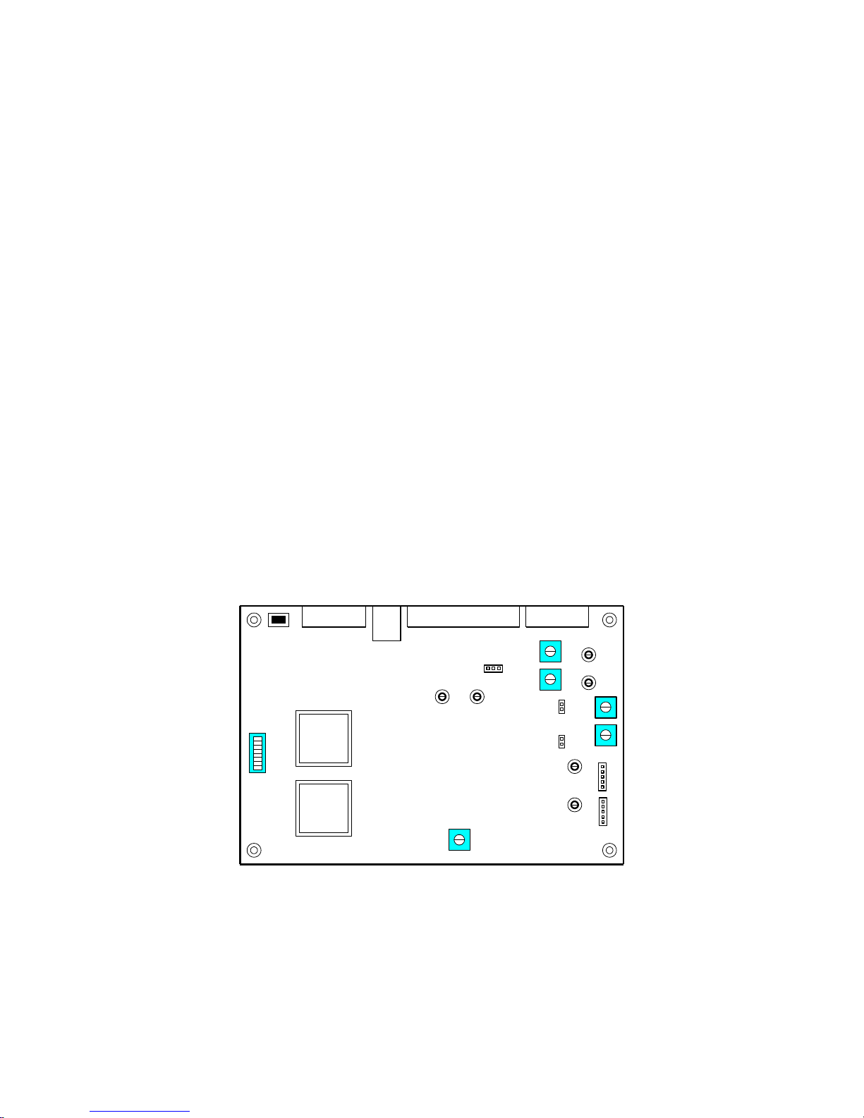
6-2
SW1
J2 J1J4
J3
TX1 TP3
RX2
RX1
TX2
TP4
TP6
TP5
PROGRAM
FIRMWARE
COR1
TP1
COR2
TP2
VOICE
ADJUST
J5
J7
J6
RX1
RX2
J9
J8
DE-EMPHASIS
JUMPER
Connector Kit
Included with the controller is a connector kit containing a 25 pin “D” connector to mate with J2, a
2.5mm power plug to mate with J3 (center pin is [+]), and two 2200 ohm resistors. If the COR inputs
are active low, you may need to install the 2200 ohm resistors as pull-ups on the board at the R10 and
R11 positions. If the receiver’s COR circuit in not capable of pulling down the 2200 ohm resistor you
may increase the value up to 10K ohms.
Power Supply
The CAT-250 is powered by an external 12VDC power supply. Connect the positive lead of the supply
to the center pin of the coaxial power connector J3 and the negative lead to the outer conductor.
Audio De-Emphasis Jumpers (J8-J9)
If the controller is supplied with discriminator audio it is necessary to de-emphasize the audio. With
the jumpers installed on J8 (Port #1) and J9 (Port #2), C32 and C33 will be connected across the
feedback resistors of the receiver audio amplifiers. This will lower the gain at the higher frequencies
and produce the necessary de-emphasis. If de-emphasize audio is supplied to the controller these
jumpers should be removed.
Audio Level Adjustment
The audio mixing-switching circuits of the CAT-250 are optimized around an input and output of –
10dBM (220mV).
Connect a signal generator to the repeater’s receiver input. Adjust the signal generator’s output for a
standard test signal of 1000 Hz at 3 KHz deviation. If a signal generator is not available, select a
handi-talkie that you suspect has the DTMF tone pad adjusted for approximately 3 KHz deviation.
Key-up on the repeater input and send a DTMF tone. Adjust the RX1 control R25 for 220mVAC at TP5.
If a link transceiver is connected to the CAT-250, key-up and send the LINK enable command [5001].
Key-up on the LINK receiver input and send a DTMF tone. Adjust RX2 control R26 for 220mVAC at
TP6.
Figure 6-1

6-3
1
LOGIC INPUT #1
14
SWITCH #1
2
LOGIC INPUT #2
15
SWITCH #2
3
CTCSS #2
16
+12VDC OUTPUT
4
CTCSS #1
17
GROUND
5
COR #2
18
GROUND
6
COR #1
19
SWITCH #3
7
SWITCH #5
20
SWITCH #4
8
SWITCH #6
21
LOGIC INPUT #3
9
PTT #2
22
LOGIC INPUT #4
10
PTT #1
23
TX AUDIO #2
11
TX AUDIO #1
24
RESERVED
12
RX AUDIO #2
25
GROUND
13
RX AUDIO #1
Once the RX1, and RX2 audios are adjusted, key-up on the repeater input and send a DTMF tone.
Monitor the REPEATER transmitter. Adjust the TX1 Audio level control (R15) as required to set the
repeater transmitter deviation to 3 KHz or as desired. If the repeaters transmit audio input is very
sensitive and you find the TX1 Audio level control near minimum, it is strongly recommended that an
external voltage divider be installed at the audio input of the repeater’s transmitter.
If a link transceiver is connected, key-up on the repeater input and send a DTMF tone. Monitor the
LINK transmitter. Adjust the TX2 Audio level control (R16) as required to set the link transmitter
deviation to 3 KHz or as desired. If the link-transmit audio input is very sensitive and you find the TX2
Audio level control is near minimum, set the jumper plug at J5 between pins 1 and 2.
Compare the receive and synthesized voice audio and adjust the voice Level (R30) as desired. The
synthesized voice should be slightly lower than the receive audio.
Unlock the CAT-250 by keying-up on the repeater input and entering: [1234567]. Key-up and enter
the [*901] test tone programming command. Verify that the test tone provides approximately 1.5 KHz
transmitter deviation. Key-up and enter [*0] to exit the programming mode.
Repeater and Link Interface (J2)
Connector J2 provides an interface to the repeater and transceiver.
Figure 6-2
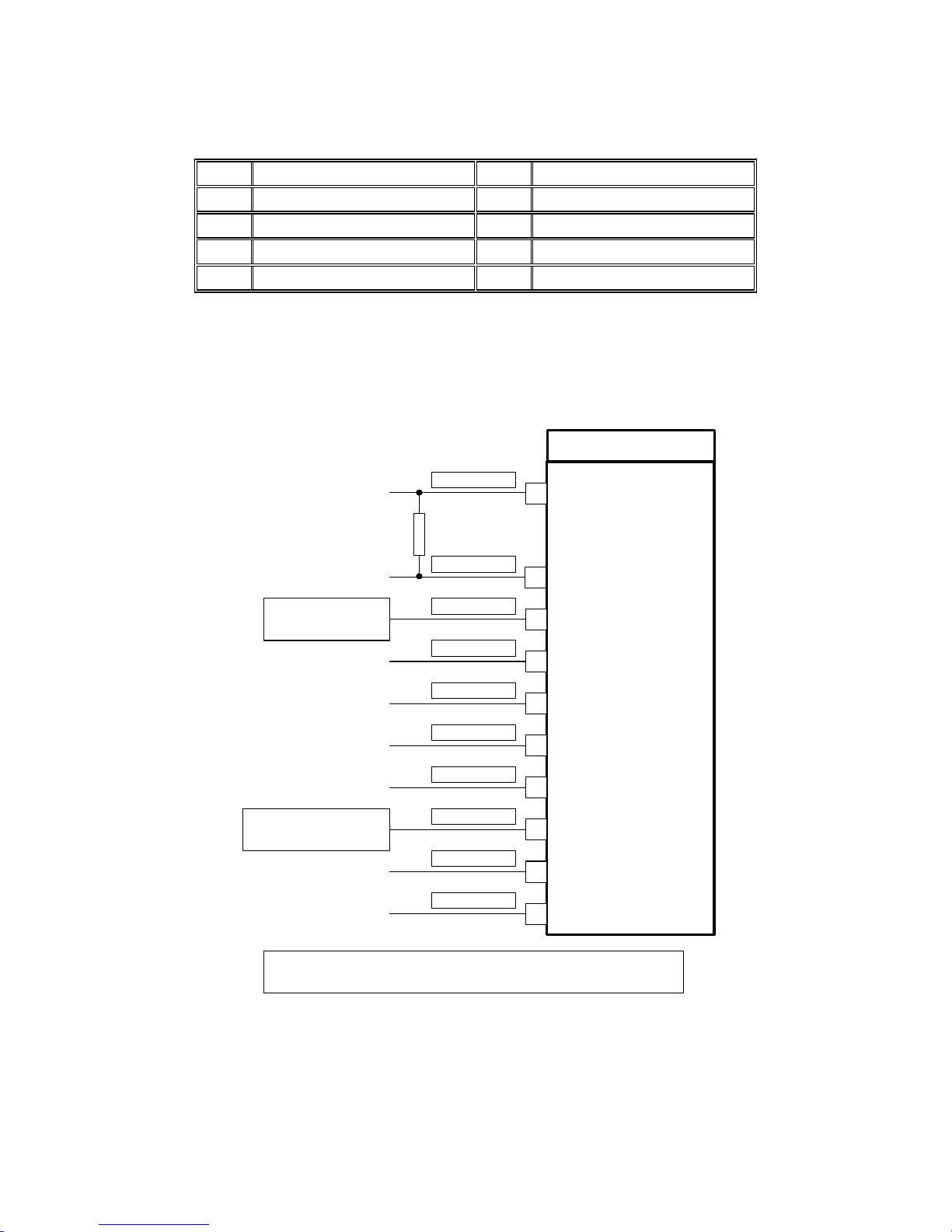
6-4
1
COR #2
6
RESERVED
2
CTCSS #2
7
RESERVED
3
PTT #2
8
GROUND
4
TX AUDIO #2
9
+12VDC OUTPUT
5
RX AUDIO #2
GROUND
TS-64WDS
RED
BLUE
ORANGE/WHITE
VIOLET
GREEN/WHITE
BLACK
YELLOW
GREEN
YELLOW/BLACK
+12VDC
CAT-250 ( J2-4)
DISCRIMINATOR
TRANSMITTER EXCITER
CAT-250 RX1 INPUT (J2-13)
2200 OHM PULL-UP RESISTOR
HIGH PASS OUT
HANG-UP
PTT INPUT
GROUND
CTCSS TONE OUT
DISCRIMINATOR
PTT OUTPUT
RX AUDIO MUTE
+12VDC
BLUE/WHITE
11
2
10
12
1
6
9
8
13
3
DISCRIMINATOR
GROUND
HIGH PASS FILTER IN
(1) TRANSMITTER PTT
OR
(2) NO CONNECTION
(1) CAT-250 PTT #1 (J2-10)
OR
(2) CAT-250 SWITCH #5 (J2-7)
To continuously transmit a CTCSS tone on the transmitter wire pins 8 and 10 per option #1
To transmit a CTCSS tone only w hen a receive signal is present, w ire pins 8 and 10 per option #2.
Program timer (*626*) for 0.1 seconds and turn on Zone 7 channel 2.
Link Interface (J1)
Connector J1 provides an alternate interface between Port #2 of the CAT-250 and the Link transceiver.
This permits the use of independent cables between the repeater and link transceiver.
Figure 6-3
CTCSS Decoder
Connect the TS-64WDS CTCSS Encoder/Decoder assembly to the CAT-250 as described in Figure 6-4.
The decoder must be connected to discriminator audio. Speaker or volume control audio will have
insufficient low frequency CTCSS tone content.
Figure 6-4

7-1
CAT-250
Chapter 7 – RS-232 Computer Interface
Connect your computer’s COMM port to the CAT-250 at J4 as described in Figure 7-1.
Figure 7-1
ISP Loader For CAT-250
Use the ISP Loader to upload the latest firmware version of the CAT-250 controller available at the
www.catauto.com web site. Under RESOURCES, select FIRMWARE UPDATES and then CAT-250
and the latest version. Follow the procedure described in the “CAT-250 Firmware Download
Instructions”.
Start the ISP Loader program to display the “ISP Loader For CAT-250” window. Follow the
directions described in the window.

7-2
Turn on dipswitch #7 and cycle power or there will not be any PTT.
ED-250W Windows Editor
Start the windows editor program to display the “CAT-250 Repeater Controller Editor” window.
Activation Of The RS-232 Port With Dipswitch #8
To activate the RS-232 port, set the DC power to OFF. Set dipswitch #8 to ON. Turn the DC power to
ON.
Activation Of The RS-232 Port By Radio
To activate the RS-232 port, key-up into Port #1 and enter the control operator prefix code [100]
followed by [97]. The voice synthesizer will say: “CONNECT” and the transmitter will drop.

8-1
Chapter 8 - Voice Vocabulary
Zero 000
One 001
Two 002
Three 003
Four 004
Five 005
Six 006
Seven 007
Eight 008
Nine 009
Ten 010
Eleven 011
Twelve 012
Thirteen 013
Fourteen 014
Fifteen 015
Sixteen 016
Seventeen 017
Eighteen 018
Nineteen 019
Twenty 020
Thirty 030
Forty 040
Fifty 050
Sixty 060
Seventy 070
Eighty 080
Ninety 090
A 210
Above 214
Again 221
Alert 223
All 224
Alpha 225
Amateur 228
An 230
And 231
Area 235
As 236
Assistance 237
At 239
Attention 241
B 250
Band 252
Base 253
Beacon 254
Below 255
Bravo 257
By 260
C 270
Call 272
Calling 273
Cancel 274
Cat 275
Caution 276
Change 279
Charlie 280
Check 281
Clear 283
Closed 285
Club 286
Code 287
Come 288
Complete 289
Condition 292
Connect 294
Contact 295
Control 296
D 310
Danger 311
Data 312
Date 313
Day 314
Days 315
Decrease 317
Delay 319
Delta 320
Direction 322
Do 323
Down 324
E 340
Echo 342
Ed (suffix) 343
Emergency 344
End 345
Enter 346
Error 348
Exit 350
F 370
Failure 372
Fast 374
Feet 376
For 004
Foxtrot 386
Frequency 388
Friday 389
From 390
Full 392
G 410
Get 412
Go 413
Golf 414
Good 415
H 440
Ham 443
Hamfest 444
Have 445
Hertz 449
High 450
Hotel 453
Hour 454
Hours 455
I 470
Ice 471
Identify 473
In 475
India 477
Information 478
Ing(suffix) 479
Inputs 480
Intruder 481
Is 482
It 483
J 500
Juliet 502
K 530
Key 531
Keypad 532
Kilo 533
L 550
Last 552
Left 554
Let 556
Lima 559
Link 561
Low 568
Lower 569
M 580
Machine 581
Macro 582
Make 583
Manual 585
Many 586
Meeting 593
Mega 594
Message 595
Meter 596
Meters 597
Mike 599
Miles 600
Minus 603
Minute 604
Minutes 605
Mobile 606
Monday 608
Month 609
Move 611
N 620
Near 621
Net 623
New 624
Next 625
Night 626
No 627
Normal 628

8-2
Not 630
November 631
Now 632
Number 633
O 650
Of 653
Off 654
On 656
Open 657
Operator 659
Or 660
Oscar 662
Out 664
Over 665
P 680
Papa 682
Per 683
Plan 688
Please 689
Plus 690
Point 691
Pound 694
Power 695
Preset 697
Q 720
Quebec 721
R 730
Radio 731
Range 735
Ready 737
Receive 738
Receiver 739
Remote 743
Repeater 746
Reset 747
Right 749
Romeo 752
S 770
Saturday 772
Seconds 774
Sent 778
Service 781
Set 782
Severe 783
Sierra 788
Snow 791
Speed 793
Star 795
Start 796
Stop 797
Storm 798
Sunday 799
System 801
S (plural) 802
T 820
Tango 821
Temperature 824
Test 826
Than 827
Thank-You 828
That 829
The(shortE) 830
The(longE) 831
Then 832
This 833
This-is 834
Thunderstorms 836
Thursday 837
Time 838
Timer 839
To 002
Today 840
Tomorrow 841
Tone 854
Tonight 842
Tornado 843
Traffic 845
Transceiver 853
Transmit 846
Try 848
Tuesday 849
Turn 850
U 870
Uniform 871
Unit 872
Until 874
Up 875
Use(noun) 876
Use(verb) 877
V 880
Victor 884
W 890
Wait 891
Warning 892
Watch 893
Watts 894
Weather 896
Wednesday 897
Week 898
Welcome 900
What 903
Whiskey 904
Will 905
With 908
X 920
X-Ray 921
Y 930
Yankee 931
Yes 934
You 936
Your 937
Z 950
Zed 951
Zone 953
Zulu 954
Pause
Pause 1 960
Pause 2 961
Pause 3 962
Pause 4 963
Time Variables
Time of Day 100
Day of Week 101
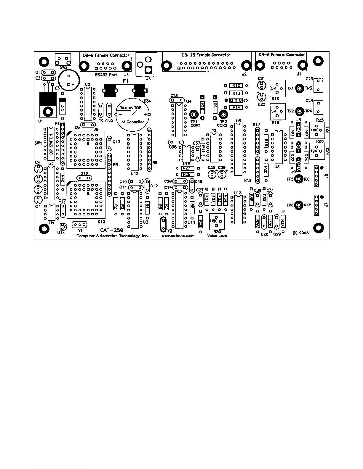
9-1
Chapter 9 - Drawings
CAT-250 Repeater Controller
Figure 9-1

10-1
Controller Board (CAT-250)
Sheet 1 of 3
Controller Board (CAT-250)
Sheet 2 of 3
Controller Board (CAT-250)
Sheet 3 of 3
Chapter 10 - Schematic

10-2

10-3

10-1

11-1
1
Capacitor
100pf
C37
1
Capacitor
.001uf 50V
C31
4
Capacitor
.0047uf 50V
C27,C30,C32,C33
2
Capacitor
.015uf 50V
C28,C29
16
Capacitor
.1uf 50V
C1,C2,C8,C9,C10,C11,C12,C13,C14,C15,C16
C17,C18,C19,C20,C36
2
Capacitor
.47uf 50V
C23,C24
8
Capacitor
10uf 16V
C4,C5,C6,C7,C21,C22,C25,C26
1
Capacitor
470uf 50V
C3 1 Capacitor
.47 Farad – 5V
C34
2
Connector
DB9 Female
J1,J4
1
Connector
DB25 Female
J2
1
Connector
DC Power
J3 1 Connector
Header 1X3
J5
2
Connector
Header 1X5
J6,J7
1
Crystal
3.58 MHz
Y2
1
Fuse
0.5 Amp Fast
F1
1
I.C.
25C640
U9 1 I.C.
89C668HBA
U10
1
I.C.
ATF1502ASL
U8 1 I.C.
LM340-05
U1 2 I.C.
LM348
U6,U13
1
I.C.
MAX335
U5 1 I.C.
MAX232
U7 1 I.C.
MCP101
U14
1
I.C.
MSP53C391
U2 2 I.C.
MT8870D
U3,U11
1
I.C.
TPIC6C595
U4 1 I.C.
ULN2804
U12
3
Resistor
100 Ohm
R14,R27,R28
2
Resistor
620 Ohm
R12,R13
2
Resistor
5K Variable
R15,R16
3
Resistor
10K Variable
R25,R26,R30
5
Resistor
10K
R23,R24,R31,R34,R40
2
Resistor
10K 6 Pin SIP
R17,R19
3
Resistor
10K 10 Pin SIP
R1,R5,R9
1
Resistor
15K
R35
9
Resistor
33K
R18,R20,R21,R22,R29,R36,R37,R38,R39
Chapter 11 - Part List

11-2
3
Resistor
82K
R32,R33
4
Resistor
100K
R2,R3,R6,R7
2
Resistor
560K
R4,R8,R11
2
Resistor
User Option
R10,R11
1
Resonator
12 MHz
Y1 1 Switch
DIP SW 8
SW1
1
Switch
Push Button
SW2
6 Test Points
TP1,TP2,TP3,TP4,TP5,TP6
1
Transorb
1N6278A
CR1
 Loading...