

Page 1
CM4200DX Remote Starter
INSTALL GUIDE
WWW.COMPUSTAR.C OM
CM4200 Alarm/Starter Control Module
This manual is for professional installers. Please read and understand this manual before you start to install.
If you have any questions, please do not hesitate to call the tech support (888)820-3690. ( 8 am to 5 pm Pacific Time)
I. Wiring Chart and Notes
1 Red 2 Gr/Wht 1: ( + ) 12v Constant 2: ( + ) Parking Light
3 Red/Wht 4 White 3: ( + ) 12v Constant 4: ( + ) Accessory
5 Violet 6 Yellow 5: ( - ) When Armed 6: ( + ) Starter
CN1
7 Gr/Red 8 Black 7: ( + ) Ignition 8: ( - ) Ground
Note 5: If the vehicle uses a
negative parking light circuit, you
can use the positive parking light
wire on this harness as a positive
trunk release output by changing
one of the onboard jumpers below.
1 Grn/Wht 2 Lt Blue 1: ( - ) Parking Lt. Output POC #1 2: ( - ) E-Brake Input
Note 1. CN3 #10 input can be
programmed either Glow Plug
(default) or Key Sensing. Option 4-
9. Then, you can select either + or
– input with the dipswitch.
3 Red/Blk 4 Lt. Blue/Wht 3: ( - ) Starter Output POC #2 4: ( + ) Brake Input
5 Green 6 Violet/Blk POC #3 POC #3 6: ( - ) Trunk Input
7 Wht/Blk 8 Red/Wht POC #4 POC #4 8: ( - ) Door Input
9 Black 10 Brown/Wht 9: ( - ) Status Out (GWR) POC #5 10: ( - ) Key Sense/Glow Input
Jumper
Cut=Auto / Uncut=Manual
11 Orange 12 Dark Org 11: ( - ) Rearm Output POC #6 12: ( - ) Slave/Timer Start Input
13 Org/Wht 14 Yel/Blk POC #7 POC #7 14: (AC) Tach / Alternator Input
15 White 16 Gray/Blk POC #8 POC #8 16: ( - ) Hood Input
CN3
17 Violet 18 Brown POC #9 POC #9 18: ( + ) Siren Output
Dipswitch (+) Door Trigger (-) Doo r Trigger
Dipswitch Glow Plug/Key-sense Polarity 1 Black Future use
Dipswitch ( + ) Trunk ( + )Parking Light 2 Violet/Wht ( - ) Trunk release output
3 Orange/Blk ( - ) Second Unlock Output
4 ( - ) 4 Blue ( - ) Unlock Output
3 ( + ) 5 Blue/Blk ( - ) Lock Output
All outputs in
CN3 and CN4
are 250 mA.
2 Data
CN4
6 Red ( + ) 12v Constant Power
1 Data
CN12
RS232
Note: 2. This port is used
for firmware updates and to
connect to bypass modules.
Black LED ( - )
Note 6: POC stands fo r
Programmable Output Connectors.
Each one of these 9 outputs can be
configured to one of the 12 outputs
as detailed later in this manual.
However, if you want to use the
channel expander, you have to
configure CN3-17(POC #9
) to Aux
1 and connect POC #9 to the data
wire of the channel expander.
Then, set up the options on 3-11
and 3-12.
1 Thermistor
CN5
LED
Black/wht LED ( + )
Note 7. LED is optional
on all systems.
2 Thermistor
CN11
Thermistor
Note 3: Thermistor is
optional on 2WLED and 1
Way sets.
1 Black ( - )
( - ) Switch 3 gray 2 White ( + )
( + ) Led 2 Gray 3 Red Tx
( - ) Led 1 Gray/Black
CN9
Plug In LED
Switch
Note 4. Used for firmware
updates and secure valet.
Option 3-10.
CN8
Antenna
4 Yellow Rx
Note 8: Tach Learning and
Engine Sensing have been
changed. See Option 2-10.
Note 9. Whenever the system fails to remote start, the vehicle provides you Diagnostic Error Messages: # of times parking lights flash. (2 Way LCD Remotes will show Strt Er##.)
1 - Engine On 2 - Key On 3 - Door Open 4 - Trunk Open 5 - Foot Brake On
6- Hood Open 7 -Reservation Off (Manual Transmission Only) 8 – No Tach or Voltage Sensing Failure
___________________________________________________________________________________________________
Note 10: Additional Items to Install
Antenna Usually mounted in the front windshield. Stay at l east 1.5 inches away from metal and mount below the tint s tripe.
LED Switch Enables the use of Secure Valet mode, mount where the customer will have convenient access.
LED Theft deterrent, LED output is 3 volts.
Thermistor Senses the current temperatur e, this item is connected to a port on the back s ide of the controller.
___________________________________________________________________________________________________
Note 11: Remote Coding Procedure
To code the remote to the system you must have; b oth 12v+ constant wire s, the ground wire, and the ignition wire of the syste m connected to the vehicle. You must have the antenna connected to the main
controller as well. After you have connected these wires or more, follow these steps to code a remote to the system. Please read through the steps before be ginning.
1. Cycle the key in the ignition from the “Off” position to the “On” position 5 times. This must be done within 5 seconds. The 5
th
time you turn the ignition on, yo u will hear the parking light
relay “click”. This will happen the moment the ignit ion is turned on the 5
th
time so it is easy to miss the first relay click. If you hear two relay clicks, the system has just exited remote
coding mode.
2. Right after cy cling the ignition for the 5
th
time and receiving the first relay click:
a. 1-Way Remote: Tap the lock button on the remote for 0.5 seconds.
b. 2-Way Remote: Tap button I for 0.5 seconds
3. After press ing the button on the remote , you will hear the parking light r elay click once to indica te that it has accepted the remote. If you have other remotes to program to the system, repeat
step 2 for each remote you have, one after the other. Each system can accept three remotes with the exception of the SS Pro.
Remote Coding – under Secure Valet – Option 3-10-III
If you elect Option 3-10-III, you can code remotes when you put the system into Secure Valet. Upon entering the secure valet code, you will hear the pa rking light relay click. Progr am a remote or remotes
until you hear two rela y clicks. See the note later in this manual regarding S ecure Valet, Optio n 3-10.
Page 2
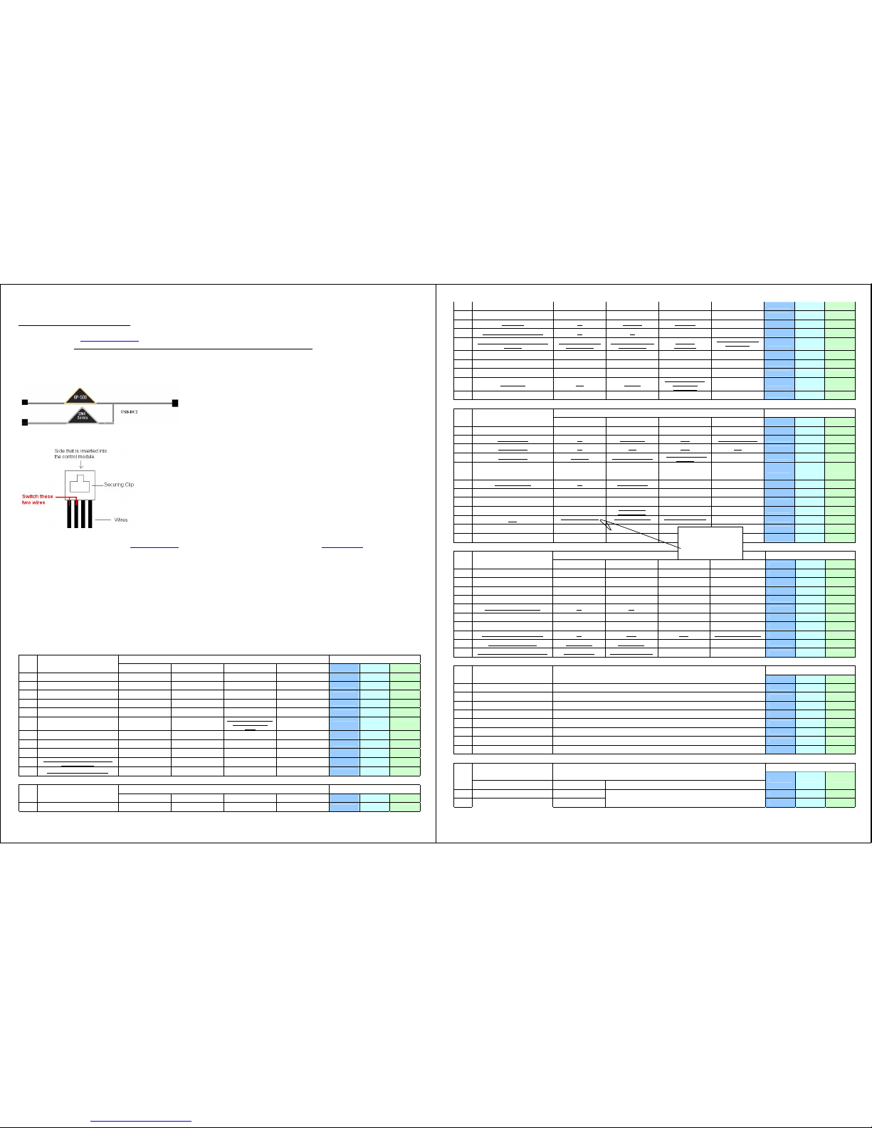
Note 12: Updating Controller Module
Look at the wiring chart of the module. If it is marked “V”, you have Version 12. If you have any other version, it will show the version
number. Please check www.compustar .com
to find out if there are any new updates. If there is any, we recommend you to update the module
before installation. All three modules, CM4000, CM4200(DX) and CM4300, use same software program.
Updating the Module.
1. You need to have a USB Uploader, the part number CST-USB-ASSY (3 components – a USB cable, a USB Module and a double head data cable.) If you already have a USB Uploader for
OP500 or iDataLink, order the double head data cable, part number USB-DC2 for free of charge. You need to pay freight. USB-DC2 is a cable connecting USB module to CompuStar and has
two connectors instead of one
Or, for a temporar y use, you may modify any of the CompuSta r antenna cable you have no w. See below.
2. Plug in USB connector to available USB port on computer. Do not have anything (idatalink, CM4000, OP500 etc) connected to the updater when connecting it to the computer.
3. Windows will a utomatically find drivers for t he USB upload cable.
4. To retrieve s oftware for updating, please email: [email protected]
. Please write “request for update software” in subject. You can also go to www.compustar.com.
Now you are read y to update your control mod ule
5. You will need to first identify what COM p ort your USB device is s et up to use. To do this , Right-click on "My Co mputer" and go to "Properties". Once the properties window is on the screen,
click the "Hardware" tap at the top of the window. Then in the main body of the window, click on the Device Manager" button. Under "Ports (COM & LPT)" There should be a device called
"USB Serial Port (COM?)", the number that is in place of the question mark is your selected com port. Disconnect the main harness; the system can not have power while you are
attempting to update its software.
6. The LED/Secure Valet switch must be connected.
7. Connect to the RS232 port of CompuStar.
8. Open the "CM4000 v12" folder, for example, and hold the LED/Valet switch button down while you double-click the file that matches your com port. Example: I use COM5 so I would use
"Update-COM5.bat". Once the LED in the LED/Valet switch starts flashing, you can let go of the button. After it is finished, just disconnect the CM4000 from the USB Updater and connect the next
CM4000 if you have more to do.
II. Option Programming Tables
Option Programming and Secure Valet are available only when “DISARMED”.
Special Option Group #1 and #2 can be programmed only with OP500.
OPTION GROUP 1
Setting Applicable To
#1 Feature
Default(I) Optional(II) Optional(III) Optional(IV)
CM4000 CM4200-DX CM4300
1-1 Unlock before, Lock after, starting. Off On Lock After Start Only
V V
1-2 Lock / Unlock pulse duration. 0.8 sec 2.5 sec 0.125 sec 3.5 sec
V V V
1-3 Driver's priority unlock Off On
V V V
1-4 Double pulse unlock. Off On
V V V
1-5 Rearm Output
After Start S hutdown and
First Lock
After Start S hutdown and
Every Lock
V V V
1-6 Reservation Lock (Manual transmission)
Locks When Reservation
Mode is Set
Does Not Lock When
Reservation is Set
Reservation Sets 10 Seconds
After the Last Door is
Closed
V V
1-7 Unlock / Disarm With Trunk Release
Unlock, Factory Disa rm, and
Trunk Release
Factory Disar m, Trunk
Release Only
Trunk Release Only
V V V
1-8 Locking while in Passive Arming
Passive locking w/ Pass ive
Arming
No Passive Locking w/
Passive Arming
V V V
1-9 Ignit ion controlled door locks Off On
RPM Locks (Tach S ensing
Mode Only)
V V V
1-10
Auto Relock (If a door is not opened within
this amount of time.)
Off 30 sec 60 sec 5 min
V V V
1-11
Ignition / Accessory Out Upon Unlock
Off
Ignition Pulse-same timing as
disarm pulse
Acc Pulse- same timing a s
disarm pulse
Ig and Acc Pulse-same
timing as disarm pulse
V V V
OPTION GROUP 2
Setting Applicable To
#2 Feature
Default(I) Optional(II) Optional(III) Optional(IV)
CM4000 CM4200-DX CM4300
2-1 Min. Crank Time Standa rd +0.2 Seconds to Cra nk Time
+0.6 Seconds to Cr ank Time
(Voltage Sensing Only)
V V
2-2 Turbo mode. Off 2 Min 1Min 4 Min
V V
2-3 Diesel timer. Wire 3~99sec (10sec Default)
V V
2-4
Trigger Start
Off Single Pulse Double Pulse
V V
2-5
Cold Start with Thermistor Assembly
Off On V V
2-6
Timer Start, or, Minimum Interval Between
Cold Starts
3 Hour (4 minute runtime,
double for Diesel)
1.5 Hour(4 minute runtime,
double for Diesel)
Reservation
(Runtime 2-7)
24 Hour Repeat with Cold
Starting of 2-8
(Runtime 2-7)
V V
2-7 Remote Start Runtime 15 Min 25 Min 45 Min 3 Min
V V
2-8 Temperature of Cold Starting Off -10° C / 14° F -5° C / 23° F 0° C / 32° F
V V
2-9 Temperature of Hot Starting Off 30° C / 86° F 35° C / 95° F 40° C / 104° F
V V
2-10
Engine Sensing
Tach Alternator
No Connection – Voltage
Not for Manual
Transmissions
V V
2-11
Turbo, Remote Sta rt Runtime Extension w/ #1
for 2 seconds
No Yes
V V
OPTION GROUP 3
Setting Applicable To
#3 Feature
Default(I) Optional(II) Optional(III) Optional(IV)
CM4000 CM4200-DX CM4300
3-1 Parking lights While Remote Sta rted Constant Output Flashing Output Off
V V
3-2
Dome Light output
Off Factory Rearm 45 sec Factory Rearm + 45 Sec V V V
3-3
Dome Light Delay
Off 5 sec 45 sec Auto V V V
3-4
Starter-Kill relay.
Anti-Grind Anti-Grind + Starter Kill
Anti-Grind + Passive
Starter Kill
V V
3-5 Anti-Jacking S tarter-kill
Ignition-Kill (no
Anti-Grind)
Auto kill (Auto-door locks
Off)
Canadian Remotes w/ AUT O
Function Only
Auto kill (Auto-door locks
On)
Canadian Remotes w/ AUT O
Function Only
V V
3-6
Factory Alarm Option
Off On (4200DX Only) V
3-7 Siren Duration (Upon Alarm Trigger) 30 sec 60 sec 120 Sec Chirps for 20 seconds
V V
3-8 Horn Output On Double Lock Only On Lock and Unlock On Lock, Unlock, and Start On Double Lock and Start
V
3-9
Horn Output (4000/4300) When Alarm Is
Triggered
Pulsed Output
(Horn)
Constant Outp ut
(Secondary Siren)
V V V
3-10
Valet
Key 5 times, or Remote
(I+III) while Ignition is On
Key 5 times or Remote
(I+III)
Secure Valet(Default code
3,3)
V V V
3-11 Channel Expander Mode Disabled Enabled
V V V
3-12
Passive Arming with Channel Ex pander
enabled
No Passive Arming Pa ssive Arming
V V V
OPTION GROUP 4
Setting Applicable To
#4 Feature
Default(I) Optional(II) Optional(III) Optional(IV)
CM4000 CM4200-DX CM4300
4-1 Aux 1 output 0.5sec Latch 20 sec Program
V V V
4-2 Aux 2 output 0.5sec Latch 60 sec Program
V V V
4-3
Aux 1 output Control By Remote Arm Disarm Panic
V V V
4-4
Aux 2 output Control By Remote Arm Disarm Panic
V V V
4-5
Secure Aux Output (1 and 2 Only)
On Off V V V
4-6 Auxiliary Input 1 Prewarn Trigger (-)Disarm
V V V
4-7 Auxiliary Input 2 Trigger Prewarn (-)Arm
V V V
4-8
Extended Accessory After Ign Shutoff
Off 10 sec 30 sec Until Door Open (1 min max) V V V
4-9
Key Sense or Glow Plug input
Glow Plug Input Key Sense Input V V
4-10
Trigger Start or Closed Loop System Input
Trigger Start input Closed Loop System Input V V V
SPECIAL OPTION GROUP #1
Applicable To
1
Feature Setting Value [seconds]
CM4000 CM4200-DX CM4300
1 Diesel timer 3 ~ 99
V V
2 AUX1 output time 1 ~ 100
V V V
3 AUX2 output time 1 ~ 100
V V V
4 AUX3 output time 1 ~ 100
V V
5 AUX4 output time 1 ~ 100
V V
6 AUX5 output time 1 ~ 100
V V
7 AUX6 output time 1 ~ 100
V V
8 AUX7 output time 1 ~ 100
V V
SPECIAL OPTION GROUP #2
Applicable To
Feature Setting Value
2
Programmable Outpu t Connector 0[Default] 1~ 12
CM4000 CM4200-DX CM4300
1 POC #1 2nd LIGHT
V V V
2 POC #2 2nd START
2nd Light[1], 2nd Sta rt[2], 2nd IG1[3 ],
2nd Acc[4], Status Out[5], Rearm Out[6],
V V
3-10 New in 4000 series.
To avoid accidental entry to
Valet Mode, yo u need to
have IG on while I+III are
p
ushe
d
Page 3
3 POC #3 2nd IG1
V V
4 POC #4 2nd ACC
V V
5 POC #5 STATUS
V V
6 POC #6 REARM
V V V
7 POC #7 DISARM
V V V
8 POC #8 HOR N
V V V
9 POC #9 DOME LIGHT
Disarm Out[7], Horn Out[8], Dome Light[9],
Aux1 Out[10], Aux2 Out[11], Defrost[12]
V V V
CM4 Series Option Menu Descriptions
1-3 Driver’s priority unlock: The driver’s door must be isolated from the other doors. Some additional installation is required. Please contact technical support for more information.
1-4 Double pulse unlock 1-4: This feature can not be used with option 1-3, drivers priority unlock.
1-5 Rearm Output: On some vehicles, if the lock button is pressed again (1-way remotes) after the system is locked/armed, and the rearm wire pulses while the factory system is already armed, the
factory alarm will be triggered.
1-6 Reservation Lo ck (Manual Transmissio n) Setting 3 will provide a 1 0 second delay befor e the vehicle shuts off aft er closing the drivers door to allow the user to open another door. 10 seconds after all
the doors are closed, if no other door is opened, the system will shut down the vehicle, s et reservation, a nd arm the alarm.
1-9 Ignition controlled door locks: Tach sensing mode must be used for this feature to work. You must also turn this feature on through the remote.
1-10 Auto Relock : If this option is turned o n, the system will automat ically relock/rearm if the system is disarmed but a door is not opened. The auto relocking can be set for 30 seconds, 60 seconds, or 5
minutes. For setting 2 , the siren will chirp and p arking lights flash every 10 s econds. For sett ing 3, the siren will chirp and parking lights flash every 20 seconds. For set ting 4, the siren will chirp a nd
parking lights flash eve ry 1 minute, 40 seconds. In every instance, on t he third chirp/parking light fla sh the system will lock/arm.
1-11 Ignition/Accessory Out Upon Unlock: Mostly new dodge vehicles need ign/acc pulse to disarm factory alarm.
2-2 Turbo mode: The e -brake must be connec ted to the control module . You must also turn on this feature through the remote .
2-3 Diesel Timer: Without setting this option you must find the vehicle’s wait to start wire. The default time for Setting 2 is 10 seconds. This can be increased or decreased only with the Option
Programmer OP500.
2-4 Trigger start: This option allows the control module to be used as a slave unit. This option determines whether the slave start wire on CN3 requires a single or double pulse to active the remote start.
This can be used on vehicles where the user would like to keep the factory remote.
2-5 Cold Start w ith Thermistor Assembly: Turning this option on will turn on the co ld/hot start feature . This option works in c onjunction with option 2-6. You must also set the temperatures in options 2-8
and 2-9.
2-6 Timer Start, o r, Minimum Interval Between C old Starts: This optio n dictates the time inter val when the control module w ill either remote start or check the temperature and remote start.
Option 1: Will start every 3 hours until the vehicle is remote started o r started by key – for 4 minutes.
Option 2: Will start every 1.5 hours until the ve hicle is remote starte d or started by ke y – four 4 minutes.
Option 3: Will sta rt at the time specifie d on the 2 way remote o ne time for the duration s et by Option 2-7.
Option 4: Will star t at the specified time on the remote every 24 ho urs if the temperature fa lls below as set und er 2-8. For example, if you want your car starts everyday 7 am in the morning for 25 minutes
when the temperature of the inside of the vehicle falls below 32°F, you need to set up:
1) Option 2-5 (Cold Start) turned on,
2) Option 2-6-IV (24 hr. repeat) turned on,
3) Option 2-7-II (25 min run-time) turned on,
4) Option 2-8-IV (Temp 32°F) turned on,
5) Set the reservation time at 7 am (see User’s guide)
6) Turn on Timer Mode of the 2 way LCD remotes (see User’s Guide)
2-10 Setting Tach/ Alternator/Voltage Se nsing
There are three modes for knowing when the vehicle has successfully started. The modes and methods of using them are listed below. These various modes can be selected in the programming menus.
1. Tachometer Wire Sensing – No Tach Learning Button in 4000 series
To lea rn the tach setting, pr ess and hold the remote -start button on the r emote for 2.5 second s while the vehicle is running with the key and your foot is on the foot brake. Tach wires can be
usually be found on the coil pack of the engine or as the odd colored wire on any of the injectors or coil packs if the vehicle has more than one.
2. Alternator W ire Sensing
This mode requires a soldered connection to a wire on the alternator that reads 0 volts DC while the vehicle is off, 4-10 volts while the ignition is on, and 12-14 volts while th e vehicle is
running. You do not need learn the alternator ou tput with this setting.
3. Voltage Sensing – No Wire Connection, Automatic Transmission Only.
This mode reads the vehicle battery volt age through the main power wir es of the system. During the start process, the system looks for changes in the voltage on those wires. Once the vehicle
has started, the voltage on the main powe r wire should jump conside rably, telling the system tha t the vehicle is now running. This mode will make it easy to ins tall the following vehicles:
1. Electronic Starter Vehicles.
Some of the newer vehicles, such as, 06 CHEVY EQUINOX, 06 SATURN VUE, 06 SATURN ION, 06 GMC DENALI, 07 GMC DENALI, 06 CADILLAC ESCALADE, 07 CADILLAC ESCALADE,
06 LEXUS RX330, 06 CHEVY COLORADO, 06 GMC CANYON come with Electronic Starting System which determines cranking time automatically by its own on-board computer upon receipt of an
electrical pulse from starter wire.
2. Vehicles in Warm Regions
In the warm regions where the temperature stays above 32º F year round, most vehicles with decent batteries start successfully with a 0.6 to 1.5 second starter p ulse. VS mode will work p erfectly with most
vehicles in these areas.
NOTE: Vehicles in Cold Regions
In the cold regions where the winter temperature falls below 32º F, the starter cranking time varies from 0.5 to 2 or 3 seconds depending on the engine temperature. In these areas, VS mode may fail to start
some vehicles early in the morning when the temperature is below 32º F and the vehicle has sat out all night. VS may work perfectly on some of newer or smaller vehicles even under these circumstances.
Unfortunately, at this time we do not know w hat types of vehicles w ill work or what types of vehicles will not work. We will continue to work o n making VS mode more intelligent so that the future
version of VS mode will w ork in these extreme te mperatures.
2-11 Turbo, Re mote Start Runtime Extension w /#1 for 2 seconds: W hen you set this option you c an reset the run time of eithe r the remote start or turbo timer. To reset the time you must hold button 1 for
2.5 seconds w hile the vehicle is remote s tarted or while the t urbo timer is running.
3-2 Dome Light Output: This option sets the timing output of the Dome Light wire on CN3.
Option 2: Factory Rearm – On this setting, the system pulses the dome light output while locking/arming the vehicle. Some vehicles need this to arm the factory alarm. (Dome Light On, Lock(Arm), Dome
Light Off)
Option 3: 45 Second Dome Light Output – activates the dome light for 45 seconds after the system is disarmed.
Option 4: Is a combination of options 2 and 3.
3-3 Dome Light Delay: This setting gives the contro l module the ability to ignore the door trigger for the set amount of time. Without this option set, if the dome light is still on when the vehicle is armed,
the remote will show the door open on the LCD display.
On options 2 and 3, if the door trigger is still active after the set time, the car will c hirp and or flash the par king lights 4 times, and the r emote will be paged (if a 2 -way remote is used) indicating that the
door is open.
Option 4: Door trigge r will be ignored until the trigge r goes away. Only use t his mode when necessary, because if the door is actually left open, you will not be notified.
3-4 Starter-Kill r elay: With this option on the default setting, the s tarter-kill relay will ac t as an anti-grind circuit only. It will not disable t he starter when the s ystem is locked/armed. On setting 2, the
starter-kill re lay will act as an anti-grind and starter-kill circ uit. Setting 3 is the sa me as 2, but a pass ive starter-kill is activated 45 seconds after the vehicle is turned off or disarmed.
3-6 Factory Alarm Option - CM4200DX Only: With this option turned on, the 4200DX starter only system will function as a factory style alar m by monitoring the door trigger and sounding the horn and
flashing the parking lights if the door is opened after the doors have been locked. Also, the two way remotes will be paged.
3-8 Horn Output – CM4200DX Only: This On default setting the horn will honk only on double lock. This is only availa ble on 1-way remotes. Optional setting 2 will puls e the horn on lock and unlo ck.
Optional setting 3 w ill pulse the horn on lock, unlock and remote star t. Optional setting 4 w ill pulse the horn on double lo ck and remote start. This will only work on 1-wa y remotes.
3-10 Valet: This o ption changes the way you p ut the system into valet mode . On default setting you c an either cycle the ignition 5 times with the key or turn the ignition on and tap buttons 1+3 – this is a
new feature in 4000 series. Setting 2 let you either cycle the ignition 5 times with the key or tap buttons 1+3 – same as CM3000 series.
Setting 3 is a secure valet: The default code is 3, 3 or any number you entered for the RPS unlock code. See the note 11 on the Wiring Chart. You can change the numbers by repeating the following steps
and the first 2 numbers of RPS unlock and secure valet codes overwrite each other.
1. Turn on Option 3-10-III.
2. Turn key to the ignition on position.
3. Hold down valet switch for 1.5 sec onds. LED on switch will b egin to
flash rapidly.
4. Tap the button on the switch to enter first number of 2-digit code. LED
will flash the first number slowly.
5. Once the LED begins flashing rapidly tap the button on the switch to
enter the second number.
6. Turn ignition off and Valet Switch is now programmed.
7. To enter valet mode follow steps 3 to 5
4-3 Aux 1 output Contr ol: These are optional e vent triggers. Default s etting triggers Aux 1 by the remot e. Setting 2 triggers Aux 1 by r emote and arming of the system. S etting 3 triggers Aux 1 by remote
and disarming of the syst em. Setting 4 triggers Aux 1 thro ugh panic of the system.
4-4 Aux 2 output Control 4-4:
Same as 4-3 except that an event triggers Aux 2.
4-5 Secure Aux Output (1 and 2 only): With this option on the default setting you must first tap button 4 on the remote and then tap either button 2 or 3 to activate Aux 1 or Aux 2. This is to prevent
accidental triggering of Aux 1 or 2 if they are hooked up to door poppers or window modules. On optional setting 2, this turns the secure aux off.
4-8 Extended Accessory After Ignition Shutoff: With this setting you can set the system to keep the Accessory wire powered up after you shut the ignition off. This can be used to keep the radio powered up
for a certain amount of time.
4-9 Key Sense of Glow Plug Input: Default setting se ts the wire as a glow plug inp ut wire. Setting 2 changes the wire into a key sense input. The key sense input can be used to prevent setting reservation
(manual transmission) a nd passive arming while the k ey is still in the ignition. Also, the dome light supervision will s top when the key is inse rted in the ignition.
4-10 Trigger Start or Closed Loop System Input: Default setting is the trigger start when using the control module as a slave unit. Setting 2 changes the wire into a closed loop system. The wire becomes an
instant trigger if the wire is separated from ground. (-) This can be used for headlights housings or connected to a tow hitch.
Special Option Gro up 1: This option group cont rols the Diesel Timer and Aux 1 though 7. Aux 3 through 7 are only a vailable with the Channel Expander. The Diesel Timer can only be set for 3 to 99
seconds. Aux 1 thro ugh 7 can be set from 1 to 100 seconds. This option group can only be accessed with the OP500 Option Programmer.
Special Option Group 2: This option group controls the Programmable Output Connectors. (POC) The POCs are located on CN3. (please see wiring guide for more details) This option group can only be
accessed with the OP500 Option Programmer. At default setting each option is set to 0. You can set each POC to 1-12. This changes the function of the POCs. Please see the option menu and wiring guide
for details of each POC.
III. How to Change Options with OP500 and Remotes
The options can be set using the OP-500 option programmer, a 1-way or 2-way remote, or the antenna if you are using an ANT-1WAM or ANT-1WSH.
Option Programming Using a 2-Way Remote
Programming the main controller option using a remote is a timed process so you should read the instructions entirely before beginning.
1. Selecting the Option Menu
Select the option menu that contains the option you would like to adjust. Be aware, the special option groups are not available when programming options with a remote. To select a menu,
use the following butt on combinations:
I+II for 2.5 sec. then I+II for 2.5 sec. Menu 1
I+II for 2.5 sec. then I+IV for 2.5 sec. Menu 2
I+IV for 2.5 sec. then I+II for 2.5 sec. Menu 3
I+IV for 2.5 sec. then I+IV for 2.5 sec. Menu 4
2. Selecting the Specific Option
After e ntering the option menu that cont ains the option you wish to c hange, tap button IV the number of times equal to the op tion number. Wait for a par king light flash and siren chirp
between each button press. A few seconds after you have stopped tapping button IV, the system will confirm which option you have selected b y the number of siren chirps a nd parking light
flashes.
3. Setting the Option
After t he system is finished confirming the op tion number, set the opt ion to your desired set ting by pressing button I, II , III, or IV.
Resetting to Fac tory Defaults
To reset the options in a menu, enter the menu as if you were going to program an option then tap button III for 0.5 sec, three times. Wait for a siren chip and parking light flash between each tap. After the
third tap, the op tion menu will reset and the s iren will chirp three times. The options in the other three menus will remain set.
Option Programming Using a 1-Way Remote
Programming the main controller option using a remote is a timed process so you should read the instructions entirely before beginning.
Page 4

1. Selecting the Option Menu
Select the option menu that contains the option you would like to adjust. Be aware, the special option groups are not available when programming options with a remote. To select a menu,
use the following butt on combinations:
(The corresponding buttons for I, II, III, IV should be listed as I = Lock, 2 = Unlock, 3 = Trunk, 4 = Start)
I+II for 2.5 sec. then I+II for 2.5 sec. Menu 1
I+II for 2.5 sec. then I+IV for 2.5 sec. Menu 2
I+IV for 2.5 sec. then I+II for 2.5 sec. Menu 3
I+IV for 2.5 sec. then I+IV for 2.5 sec. Menu 4
2. Selecting the Specific Option
After entering the option menu that contains the option you wish to change, [hold buttons III and IV until the parking lights flash, then release] the number of times equal to the option
number you wish to change. Wait for a parking light flash and siren chirp between each button press. A few seconds after you have stopped selecting an option, the system will confirm
which option you have s elected by the number of s iren chirps and parking light fla shes.
3. Setting the Option
After the system is finished confirming the option number, set the option to your desired setting by pressing button(s); [I] for 0.5 sec. for the default option, [II] for 0.5 sec. for optional
setting 2, [III] for 2.5 sec. for optional setting 3, and [III+IV] for 2.5 sec. for optional setting 4.
Resetting to Fac tory Defaults
To reset the options in a menu, enter the menu as if you were going to program an option then tap the start button for 0.5 sec, three times. Wait for a siren chip and parking light flash between each tap.
After the third tap , the option menu will reset and the siren will chirp thre e times. The options in t he other three menus will remain set.
Option Programming Using the 1-Way Antenna Button
Programming the main controlle r option using an antenna is a timed process so you s hould read the instruct ions entirely before beginning.
1. Turn vehicle’s ignition to the on position.
2. Selecting the Option Menu
Select the option menu that contains the option you would like to adjust. Be aware, the special option groups are not available when programming options with an antenna. To select a menu,
use the following butt on combinations:
Hold antenna button unt il you hear/see 1 chirp/p arking light flash. M enu 1
Hold antenna button unt il you hear/see 2 chirps/ parking light flashes. Menu 2
Hold antenna button unt il you hear/see 3 chirps/ parking light flashes. Menu 3
Hold antenna button unt il you hear/see 4 chirps/ parking light flashes. Menu 4
3. Selecting the Specific Option
After e ntering the option menu that cont ains the option you wish to c hange, tap the antenna button the number of times equal t o the option number you wish to c hange. A few seconds a fter
you have stopped selecting an option, the system will confirm which option you have se lected by the number of sir en chirps and parking light flas hes.
4. Setting the Option
After t he system is finished confirming the op tion number, set the opt ion to your desired set ting by tapping the antenna butt on 1,2,3, or 4 times.
Resetting to Fac tory Defaults
To reset the op tions in a menu, enter the menu a s if you were going to progra m an option then hold the antenna button for three seco nds. The option menu will res et and the siren will chir p three times. The
options in the other three menus will remain set.
Option Programming Using the OP-500
The OP-500 is required to program options in the Special Option Groups 1 and 2.
1. Connection to Control Module
Using the blue connector on the top of the OP-500, connect it to the control module via the antenna wire. (Use the included extension cable if necessary.) Once connected, the OP-500 will
power up. (The c ontrol module must have 12v+ and ground.)
2. Setting Options in Option Menu and Special Option Groups
To change the option number you wish to program, use the left and right arrow keys on the OP-500, it will scroll through then options available in me nu 1 and then move to menu 2, then 3
and 4. At the end of menu 4 , if you have turned on diese l mode or the channel expand er, or set any of the a uxiliary outputs to “Progra m”, you will have the option to program the duration of
the diesel timer and /or auxiliary outputs. Afte r the aux and diesel se ttings (if selected), the POC options will b e displayed. The “POCs” are the programmable outputs on CN3 of the ProSeries modules. Please refer to the installation guide of the main controller for more information.
You can then use the up and down arrow buttons to adjust the option’s settings. “1” is the default setting, and “2”, “3”, and “4” are the optional settings. The timing of the aux outputs and of
the diesel timer is displayed in seconds, and the POCs can be set between 0 (default) and 12. If you wish to restore all of the factory defaults, you can press “R” and “W” until the OP-500
chirps.
3. Finalizing Option Se ttings to Control Module
When you are done adjusting the various option settings or resetting them to the factory defaults, press and hold the “W” (write) button until
the OP-500 chirps. This will write the settings to the control module. Wait until the module displays “Success” before disconnecting it from
the antenna cable.
Updating the OP-500
This is required if you have an early version of the OP-500
1. To retrieve s oftware for updating p lease email: [email protected]. Please write “request for update software” in subject. You can also go to www.compustar.com
2. You will need to first identify what COM p ort your USB device is s et up to use. To do this , Right-click on "My Co mputer" and go to
"Properties". Once the properties window is on the screen, click the "Hardware" tap at the top of the window. Then in the main body of the window, click on the Device Manager" button.
Under "Ports (COM & LPT)" There should be a device called "USB Serial Port (COM?)", The number that is in place of the question mark is your selected com port.
3. Connect the USB Updater to the computer, do not have anything (idatalink, CM4000, OP500 etc) connected to the updater when connecting
it to the computer. After a few seconds, connect the USB Updater to the "USB" port on the OP500 using the supplied cable. Open the "OP500 v6.2" folder and hold the "W" button on the
OP500 down while you double-click the file that matches your com port.
Example: I use COM5 so I would use "UPDATE-V6-COM5.bat". Once the OP500 displays "UP" on the screen, you can let go of the "W" button. After it is finished, just disconnect the OP500
from the USB Updater and connect the next OP500 if you have more to do.
 Loading...