

Page 1
Bedienungsanleitung
für Statox 501 Controller
Inhaltsverzeichnis
1. Der Statox 501 Controller
2. Inbetriebnahme
2.1 Montage
2.2 Anschluss der Versorgungsspannung
2.3. Bedienung des Statox 501 Controllers
2.3.1 Das Passwort-Menü
2.3.2 Einstellen des Betriebsprogramms
2.3.3 Einstellungsmöglichkeiten Alarme
2.4 Anschluss der Messköpfe
2.5 Justierung von Messköpfen für brennbare
Gase
3. Statusmeldungen und Fehlersuche
4. Technische Daten
Bitte unbedingt beachten !
- Lesen Sie bitte vor der Inbetriebnahme
diese Bedienungsanleitung.
- Die Betriebsspannung des Kontroll- und
Sammelalarmmoduls beträgt 24 VDC.
Höhere Spannungen zerstören die
Module.
- Kurzschlüsse an den Klemmen können
ebenfalls zu einer Zerstörung der Module
führen.
- Wählen Sie das richtige Betriebs-
programm vor Anschluss eines Messkopfes. Ein falsches Betriebsprogramm
kann einen angeschlossenen Sensor
zerstören.
- Kontroll- und Sammelalarmmodul dürfen
nicht in explosionsgefährdeten
Bereichen betrieben werden.
- Bei der Installation sind die
einschlägigen VDE-Normen und Vorschriften zu beachten.
- Messköpfe für toxische Gase in Zone 1
dürfen nur zusammen mit einem
Speisetrenner betrieben werden.
- Messköpfe für brennbare Gase können
direkt an den Controller angeschlossen
werden.
- Weitere Hinweise finden Sie unter
http://www.compur.com.
Operation Instructions
Statox 501 Controller
Content
1. Statox 501 Controller
2. Start-up
2.1 Installation
2.2 Connecting the power supply
2.3. Operation of the controller
2.3.1 The password menu
2.3.2 Programming to the sensor head
2.3.3 Alarm parameter options
2.4 Connecting the sensor heads
2.5 Calibration to combustible gases
3. Status messages and troubleshooting
4. Technical Data
Caution !
- Read and observe this manual prior to
any setup or installation work.
- The control and the common alarm
module operate at 24 VDC. Higher
Voltages will destroy the modules.
- Short circuits at any terminal can destroy
the modules.
- Select the appropriate program before
connecting the sensor head. Operating a
sensor head with the wrong program may
destroy the sensor.
- Control module and common alarm
module are not designed to operate in
classified areas.
- Observe local regulations and standards
when installing the system.
- Operating sensor heads for toxic gases or
oxygen in classified areas with a risk of
explosion requires an intrinsically safe
repeater to be installed between
controller and sensor head.
- Sensor heads for combustible gases can
be connected directly to the control
module.
- More information see
http://www.compur.com.
Page 2

1. Der Statox 501 Controller
Der Statox 501 Controller dient zur Energieversorgung, Signalanzeige und Auswertung sowie als
Alarmmodul für Gaswarnsysteme der Serie 501
von Compur Monitors. Der Statox 501 Controller ist
gasneutral und wird durch die Wahl des
entsprechenden Betriebsprogramms an den
Messkopf angepasst.
2. Inbetriebnahme
Halten Sie sich bitte an folgende Reihenfolge, um
die Module nicht zu beschädigen:
Montage der Statox 501 Controller, Netzteil und
Speisetrenner Pkt. 2.1
Anschluss an die Versorgungsspannung Pkt.2.2
Einstellen des Betriebsprogramms Pkt. 2.3.2
Einstellen der Alarmschwellen Pkt. 2.3.3
Anschluss des Messkopfes Pkt. 2.4
Erstjustierung bei Messköpfen für brennbare
Gase Pkt. 2.5
2.1 Montage
Das Modul mit der unteren gefederten Raste auf
die DIN Schiene schieben und nach oben drücken
bis die obere Raste ebenfalls einrastet. Seitlich verschieben bis es mit dem danebenliegenden Modul
abschließt. Die Module des Statox 501 Systems
können beliebig kombiniert werden. Um den
Verdrahtungsaufwand zu minimieren empfiehlt es
sich das Netzteil stets ganz links auf der Schiene
zu montieren. Nur der erste Controller in einer
Reihe muss an 24 V DC angeschlossen werden,
alle weiteren werden über den Busstecker versorgt.
Die Busleitungen sind zur Versorgung von max. 10
Controllern in einem Strang ausgelegt. Die Parallelschaltung mehrerer Stränge ist möglich.
Zur Vermeidung von EMV-Einflüssen muss der
Schirm aller Messkopfleitungen auf die Masseschiene aufgelegt werden. Außerdem müssen die
Masseschiene und die DIN-Schiene geerdet werden.
Tipps
- Beim 19“ Baugruppenträger Module an der
vorderen, Speisetrenner (kopfüber) und
Netzteil an der hinteren Schiene montieren.
- Das Sammelalarmmodul sitzt rechts als
letztes Modul. Die Alarmsignale der Controller
werden über den Busstecker durchgeschleift.
- Besteht ein System aus mehreren übereinanderliegenden Reihen von Controllern,
können diese mit dem Busverbinder Art.nr.
559417 verbunden werden. Beachten Sie,
dass die Busleitungen zur Versorgung von
maximal 10 Controllern ausgelegt sind.
1. The Statox 501 Controller
The Statox 501 Controller operates as the power
supply, display, signal manager and alarm module
for any sensor head of Compur’s Statox 501 gas
detector series. It is not gas specific. It is
programmed to the relevant gas by selecting the
appropriate program and gas label.
2. Start-up
Proceed step by step in the following sequence:
Install the Statox 501 Controller, power supply
and intrinsically safe repeater Pt. 2.1
Connect the power supply Pt. 2.2
Select program Pt. 2.3.2
Set the parameters Pt. 2.3.3
Connect sensor head Pt. 2.4
Calibrate (combustible gases) Pt. 2.5
2.1 Installation
The modules of the Statox 501 system can be
installed in any sequence. The most economic
installation is to mount the power supply on the left
side. In this position, the only controller that needs
to be wired is the one next to the power supply. All
other controllers will be powered via the controller
bus system. The bus can supply up to 10 modules
in one line. It is possible to connect bus lines in
parallel.
To connect the control module to the DIN rail, push
the lower slot of the module against the rail and
press upwards until the upper slot snaps into place.
Slide the module along the rail until it connects to
any existing module.
To protect the system from electromagnetic
interference, the shield of all signal cables must be
connected to the grounding rail. The grounding rail
must be connected to ground.
Tips
- Install modules in the 19“ carrier on the front
side, repeaters on the back.
- The common alarm module should be
installed on the right side. It receives the
alarm signals via the bus connector.
- If more than one line of controllers shall be
connected to the common alarm module, use
the optional bus connector (part # 559417).
The bus is not suitable to supply more than 10
modules in one line!
Page 3
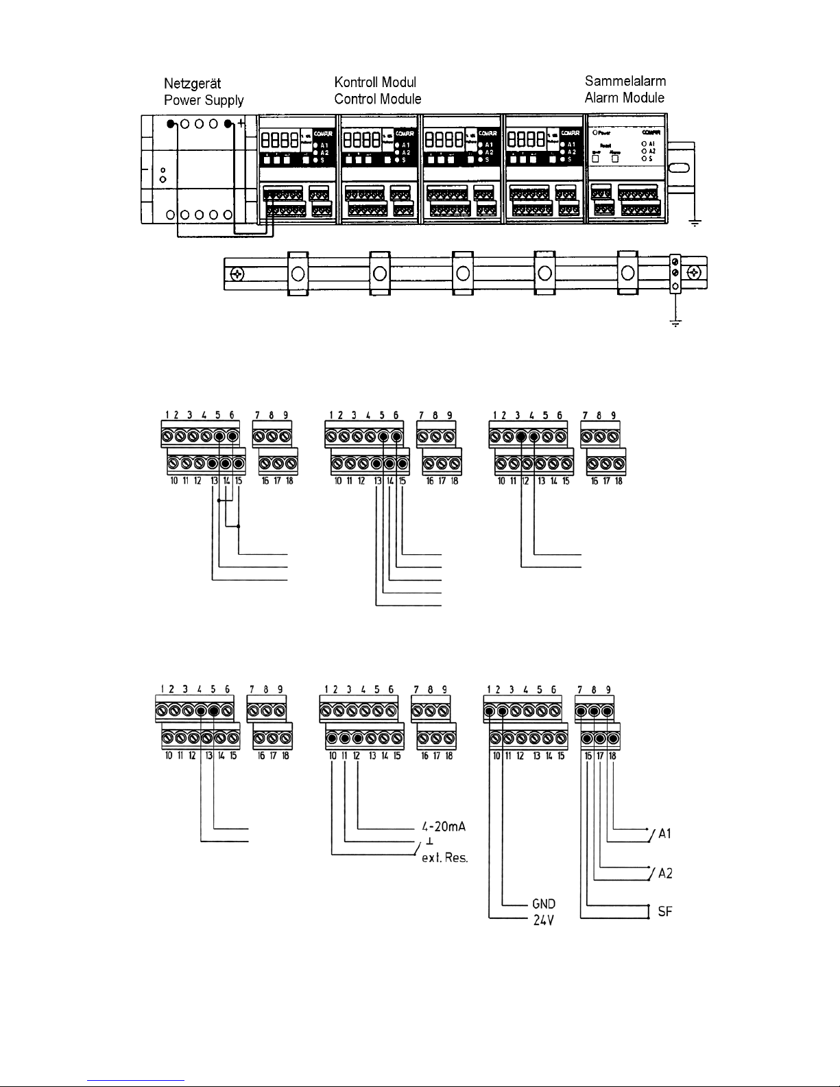
Bild 1: Montagebeispiel
Picture 1: Mounting example
I
i
24 V
4 oder/or 5
1 oder/or 2
3
5
1
4
2
Bild / Picture 2c
A
nschluss des 4-20 mA Transmitters für
tox. Gase mit Speisetrenner
Connection of 4-20 mA transmitters for
toxic gases with repeater
Bild / Picture 2a
3-Drahtanschluss
3-Wire operation
Bild / Picture 2b
5-Drahtanschluss
5-Wire operation
19 V
I
i
Bild / Picture 2d
A
nschluss des 4-20 mA Transmitters
für tox. Gase ohne Speisetrenner
Connection of 4-20 mA transmitters for
toxic gases without repeater
Bild / Picture 2e
Signalausgang und
externer Reset
Signal output and
external reset
Bild / Picture 2f
A
nschluss der Versorgungsspannung
und der Relaiskontakte
Power supply terminal and relay
outputs
Bild 2: Klemmenbelegung Vorderseite
Picture 2: Front-side terminals
Page 4

2.2 Anschluss der Versorgungsspannung
Die Versorgungsspannung 24 V/DC wird an den
Klemmen 1 und 2 angeschlossen (siehe Bild 2 f).
Den Controller niemals direkt an 230 V anschliessen! Kurzschlüsse an den Klemmen können das
Gerät zerstören! Alle Klemmen eignen sich zum
Anschluss von Leitungen bis 1.5 mm
2
Querschnitt.
Nach Anschluss an die Spannungsversorgung
führt der Controller einen Selbsttest durch. LED „S“
leuchtet. Es erscheint kurz die Versionsnummer
der Software und anschließend die Nummer des
aktuellen Betriebsprogramms, danach „----“.
Da der Messkopf noch nicht angeschlossen ist,
wird nach einiger Zeit ein Fehler gemeldet (Er 2
oder Er 5). Stellen Sie nun wie unter Punkt 2.3
beschrieben das erforderliche Betriebsprogramm
und die gewünschten Parameter ein.
2.3 Bedienung des Statox 501 Controllers
2.3.1 Das Passwort-Menü
Durch gleichzeitiges Drücken von ▲ und ▼
gelangen Sie vom Fehler- oder Messmodus
(normaler Betriebszustand) in den Servicemodus.
Hier können Parametrierung und Justierung
vorgenommen werden.
Solange Sie sich im Servicemodus befinden, blinkt
die LED „S“. Für ca. 2 Sekunden erscheint “PASS”,
danach “-00-“. Die linke Ziffer blinkt. Stellen Sie mit
den up- und down Tasten die entsprechende
Code-Ziffer ein und bestätigen Sie mit Enter.
Verfahren Sie mit der zweiten Ziffer genauso. Über
folgende Codes erhalten Sie Zugang zu den
verschiedenen Menüs:
“11” Justierroutine und Brückenspannungs-
anzeige im Spannungsmodus. Dieser Code
ist nur bei Messköpfen für brennbare Gase
gültig.
“22” Alarmschwelleneinstellung A1 und A2,
Konfiguration der Relais, Test der Relais
und des Stromausganges, Abschalten der
Versorgungsspannung.
“33” Auswahl des Betriebsprogramms.
Das Modul kehrt mit Taste „R“ oder wenn 30s lang
keine Taste gedrückt wird in den Messmodus
zurück.
Dieser Time-out ist nicht aktiv
- bei Nullpunktabgleich und Gaskalibrierung
- beim Ein-/Ausschalten der Sensorversorgungsspannung im Menüpunkt „USEn“ (Display zeigt
„On“ oder „OFF“)
- nach Bestätigung der gewählten Programmnummer.
2.2 Connecting the power supply
Connect 24 V/DC power supply to terminals 1 and
2 (see Pct. 2 f).
Never connect the controller to 230 V or 115 V
mains! Short-circuiting the terminals can destroy
the instrument! The terminals are designed to
accept wires up to 1.5 mm
2
diameter.
Connect the power supply. The control module will
now perform a system test. The “S“ LED will turn
on. The display will show the software index for a
moment and then the active program. Now the
module will try to adjust its output voltage to the
sensor head and display “----“. Since the sensor
head is not yet connected, an error message (Er 2
or Er 5) will appear on the display. Proceed to
select the appropriate program (see 2.3).
2.3 Operating of the Statox 501 Controller
2.3.1 The password menu
Push ▲ and ▼ at the same time. By doing this you
leave the normal operation mode and enter the
service mode. Entering this mode will allow the
user to alter system parameters or calibrate the
system.
As long as the service mode is active, the “S“ LED
will continuously flash. For 2 seconds, “PASS”
appears on the display and then “-00-“ with the left
digit flashing. You now have access to the
following menus:
“11” Calibration routine and display of the bridge
voltage. This program is only applicable for
combustible gas sensor heads
“22” Alarm threshold setting A1 und A2, relay
configuration, test of the relays and
analogue output, switching off the sensor
head power supply for service work.
“33” Selection of the operation software
program.
Enter the relevant code using the up- and down
button. Confirm each number by pressing the
”Enter“ button. To leave the service mode at any
time, push the “R“ button. If no button is touched
within 30 seconds, the control module will time-out
and leave the service mode automatically.
This time-out is not active
- during zero and span adjustment
- when switching the sensor power supply on or
off in the menu “USEn” (display shows “On“ or
“OFF“)
- after confirmation of the selected program.
Page 5

Bei Eingabe eines falschen Codes wird “Err”
angezeigt und das Modul bleibt im Pass-Menü.
Alle Prozeduren sind in den folgenden Ablaufdiagrammen dargestellt. In den Kästchen steht die
jeweilige Anzeige, neben oder über den
Sequenzpfeilen steht ein Symbol der zu
drückenden Taste.
R Resettaste ↵ Enter
▲ Up ▼ Down
2.3.2 Einstellen des Betriebsprogramms
(Ablaufschema 1, Code 33)
Wählen Sie aus der Messprogrammliste im
Anhang das für Ihren Messkopf passende
Betriebsprogramm und stellen Sie es nach
Ablaufschema 1 ein.
Achtung: Beim Wechsel des Betriebsprogrammes
gehen die vorhandenen Justierdaten verloren!
Jedem Controller liegt ein Bogen mit
Gaseschildern bei. Kleben Sie das entsprechende
Schild rechts neben die Anzeige des Contollers.
2.3.3 Einstellungsmöglichkeiten Alarme
(Ablaufschema 2, Code 22)
Die Auslöseschwellen für die Alarme A1 und A2
können frei gewählt werden. Ausserdem können
Sie festlegen, ob die Alarme bei Über- oder
Unterschreiten der Schwelle ausgelöst werden und
ob sie haltend oder selbstlöschend sind.
Die Relais können im Alarmfall aktiv (Schließer)
oder passiv (Öffner) sein. Anschlüsse der
Relaiskontakte siehe Bild 2 f.
Bei einem anstehenden Alarm leuchten die LEDs
A1/A2 und die Alarmrelais schalten. Alarme
können erst dann zurückgesetzt werden, wenn die
entsprechende Konzentration nicht mehr ansteht.
Der Alarmreset kann über die Taste R oder mit
dem externen Reset über die Klemmen 10 und 11
erfolgen (Anschluss externer Reset: Bild 2 e).
Mit der Routine „ tESt“ können die Alarmrelais und
der 4-20 mA Analogausgang getestet werden. Mit
der Routine „USEn“ kann die Messkopfversorgung
zu Servicezwecken abgeschaltet werden (kein
Time-out während der Anzeigen „On“ und „OFF“!).
If a wrong or irrelevant code is entered, the display
shows “Err” and the module remains in the “pass”
menu.
All procedures are described in the following
schematics. In the boxes, the relevant display text
is indicated. Next to the sequence arrows you find
a symbol of the button to operate
R Reset ↵ Enter
▲ Up ▼ Down
2.3.2 Selecting the operation program
(diagram 1, code 33)
In this menu you select the appropriate operation
program for gas type, range and voltage. Refer to
appendix 1, program list.
Caution! A program change deletes all calibration
parameters.
Each controller comes with a set of gas component
labels. Choose the relevant label and stick it next
to the right hand side of the display.
2.3.3 Alarm parameter setting
(diagram 2, code 22)
In this program mode, the alarm thresholds and
the relay configuration may be accessed and
changed.
The following options are programmable: 2 alarm
thresholds, relays normally open or normally
closed, active or passive, high or low alarm,
latching alarm or auto-reset. See Pct. 2 f.
In the event an alarm condition has occurred, the
LEDs A1/A2 will turn on and the relevant relays
will be activated. An alarm condition can only be
reset by pushing the reset button or by externally
reseting (terminals 10 and 11) if the gas concentration has dropped below the alarm level.
External alarm reset connection see Pct. 2 e.
Under the “test” menu, the proper function of the
alarm relays, the 4-20 mA analog output and
connected devices can be tested. Selecting the
“USEn” menu the sensor head power supply can
be switched off for maintenance or service work.
(There are no time-outs as long as “ON“ or “OFF“
is displayed!).
Page 6
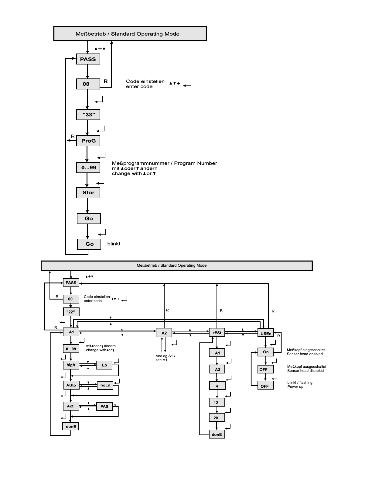
Ablaufschema 1: Einstellen des Betriebsprogramms
Diagram 1: Selecting the operating software program
Ablaufschema 2: Konfiguration der Alarmschwellen
Diagram 2: Setting the alarm parameters
Page 7

2 .4 Anschluss der Messköpfe
Anschluss der Messköpfe nur im
spannungsfreien Zustand vornehmen! Kurzschlüsse an den Klemmen unbedingt vermeiden!
Messköpfe für brennbare Gase können im
3- oder 5-Drahtanschluss betrieben werden.
3-Drahtanschluss kann bei Leitungslängen bis 750
m und geringen Schwankungen der Umgebungstemperatur gewählt werden (Bild 2a).
5-Drahtanschluss immer bei Leitungslängen über
750 m oder großen Schwankungen der Umgebungstemperatur wählen. Mit den beiden
zusätzlichen Senseleitungen kompensiert der 501
Controller alle leitungs- und temperaturbedingten
Schwankungen der Spannungsversorgung des
Messkopfes (Bild
2b).
Messköpfe für toxische Gase und Sauerstoff
sind als 4-20 mA Transmitter (Strommodus) für
2-Drahtanschluß ausgeführt (Bild 2 d).
Diese Messköpfe sind in der Ex- Schutzart Eigensicherheit EEx ib IIC T5/6 ausgeführt und müssen
über einen Speisetrenner versorgt werden, wenn
sie in Zone 1 betrieben werden sollen. (Bild 2 c)
Nach dem Anschluss der Messköpfe starten Sie
die Controller mit der Enter-Taste. Es erscheint
„- - - -“ im Display. Anschließend wird der aktuelle
Messwert angezeigt und die LED „S“ erlischt.
2.5 Justierung von Messköpfen für brenn-
bare Gase (Ablaufschema 3, Code 11)
In diesem Menü können Messköpfe für brennbare
Gase justiert werden. Außerdem stellt es eine
Anzeige der Brückenspannung (Menü „Ubr“, in
mV) als Kriterium für den „Verschleißvorrat“ des
Sensors zur Verfügung. Bei Betriebsprogrammen
mit Messbereich 0-100% UEG muss die
Prüfgaskonzentration zwischen 10% und 100%
UEG liegen. Beim Nullpunktabgleich darf kein Gas
vorhanden sein, im Zweifelsfall muss synthetische
Luft verwendet werden !
2 .4 Connecting the sensor head
Caution: Only connect sensor heads with
the power supply disconnected or switched off.
Avoid short circuits at any terminal!
Combustible gas sensor heads can operate in
the three or five wire mode (voltage mode).
3-wire mode: Applicable if the cable is less than
2,460 ft long and there are no extreme ambient
temperature variations (see Pct. 2a).
5- wire mode: Applicable if the cable is more than
2,460 ft long or there are extreme ambient
temperature variations possible. The two additional
”sensing” leads compensate for temperature- or
cable resistance related drops of the sensor supply
voltage (see Pct.2 b).
Toxic gas and oxygen sensor heads are 4-20
mA transmitters (current mode) designed for 2-wire
connection. (Pct. 2 d)
These sensor heads are certified EEx ib IIC T5/6
and must be connected via an intrinsically safe
repeater if they are installed in a classified area
with risk of explosion. (Pct. 2 c)
After having the sensor head connected push the
Enter button to restart the system.
2.5 Combustible gas sensor head
calibration (diagram 3, code 11)
In this menu you can calibrate combustible gas
sensors. For calibration, the span gas concentration must be between 10% und 100% LEL.
“Zeroing” the sensor must only be done in a clean
air environment. If you are unsure about the quality
of the ambient air, use synthetic air!
In addition to calibration, the wheatstone bridge
voltage of the sensor can be displayed in mV by
selecting “Ubr“. This is a good indication for the
remaining lifetime of the sensor.
Page 8
3. Statusmeldungen und Fehlersuche
Die auf dem Display angezeigten Meldungen
haben folgende Bedeutung:
- - - - Programmstart
PASS Passwort-Menü
ProG Programmwahl
Stor Einstellungen gespeichert
A1 Alarmschwelle 1
A2 Alarmschwelle 2
high Alarm bei Überschreiten von A1 / A2
Lo Alarm bei Unterschreiten von A1 / A2
Auto Alarm selbstlöschend
hoLd Alarm haltend
Act Relais aktiv
PAS Relais passiv
donE Prozedur abgeschlossen
USEn Sensorspannung
CAL Kalibrierroutine
GAS Kalibriergas aufgeben
SEnS Sensor zu unempfindlich
tESt Testroutine für Peripheriegeräte
Ubr Brückenspannung
SerU 4-20 mA Transmitter im
Servicemodus
100 blinkt Messwert größer als 100 % UEG
On Messkopf eingeschaltet
OFF Messkopf ausgeschaltet /
Kurzschluss bei Error 2
3. Status messages and troubleshooting
The displayed messages have the following
meanings:
- - - Program start
PASS Password menu
ProG Program selection
Stor Settings stored
A1 Alarm level 1
A2 Alarm level 2
high High alarm
Lo Low alarm
Auto Alarm auto reset
hoLd Alarm latching
Act Relay active
PAS Relay passive
donE Procedure finished
USEn Sensor voltage
CAL Calibration routine
GAS Span gas on
SEnS Sensor lost sensitivity
tESt Test routine for peripheral devices
Ubr Bridge voltage
SerU 4-20 mA Transmitter in service
mode
100 flashing Concentration over 100 % LEL
On Sensor head on
OFF Sensor head off / Short circuit in
case of Error 2
Die Funktionen CAL und Ubr
stehen nur im Spannungsbetrieb
zur Verfügung !
Functions CAL and Ubr only in
voltage mode !
blinkt / flashing
Gas abdrehen / shut off cal gas
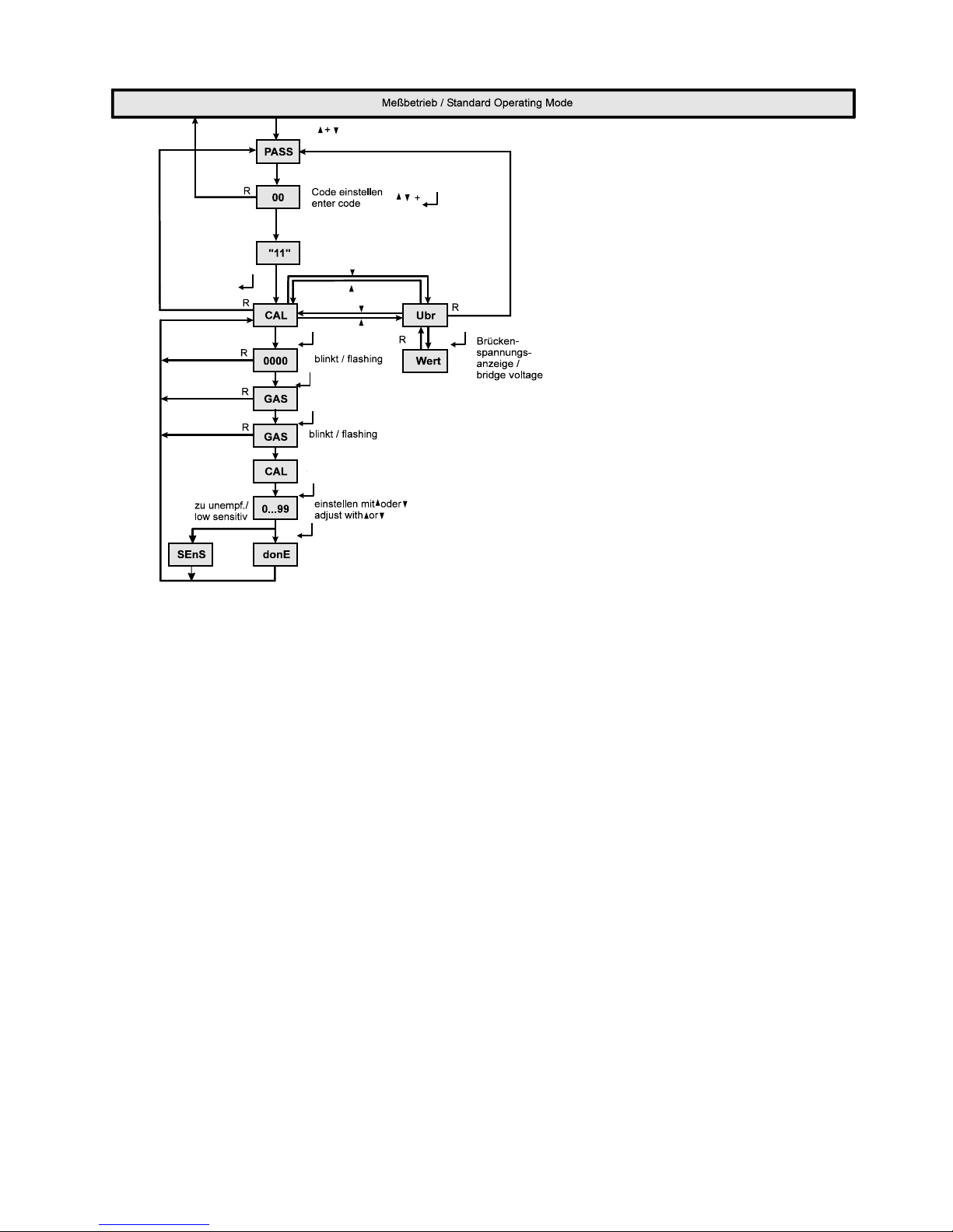
Ablaufschema 3: Justiermodus
Dia
g
ram 3: Calibration mode
Page 9

Fehlermeldungen:
Der Statox 501 Controller überwacht zahlreiche
Funktionen automatisch. Außer bei Stromausfall
werden Fehlercodes im Display angezeigt. Mit
Ausnahme von Er 6, Er 7, Er 8 und SEnS wird
auch das Systemfehlerrelais geschaltet und die
LED „S“ leuchtet.
Fehlermeldungen und Abhilfemaßnahmen:
Er 1 Kurzschluss in der Leitung zum Sensor:
Fehler beseitigen, Enter drücken.
Er 2 Leitungsbruch (nur im Strommodus):
wird nach Verschwinden der Fehlerursache
automatisch zurückgesetzt. Bei Kurzschluss während Er 2: Anzeige „OFF“,
Fehler beseitigen, Enter drücken.
Er 3 Leitung zu lang (nur im Spannungsmodus):
Leitung prüfen, Kurzschluss beseitigen,
Messkopf anschließen, mit Enter die
Stromversorgung einschalten.
Eventuell 5-Draht-Anschluss wählen!
Er 4 Die Spannung der Sensorstromversorgung
lässt sich nicht regeln: Entertaste drücken
um die Stromversorgung einzuschalten.
Ansonsten Kundendienst rufen.
Er 5 Leitungsbruch (nur im Spannungsmodus):
Versorgungsspannung am Messkopf
prüfen, Sensoranschluss prüfen, Messkopf
anschließen, Entertaste drücken.
Er 6 Nullpunkt lässt sich nicht innerhalb des
Zeitfensters einstellen: Anschlüsse prüfen,
ist evtl. Gas vorhanden? Nach Drücken der
Entertaste arbeitet das Programm mit dem
altem Nullpunkt weiter.
Ansonsten Sensor wechseln.
Er 7 Nullpunktabweichung zu groß:
Entertaste drücken, Messung wird mit
ursprünglicher Einstellung weitergeführt.
Ist evtl. Gas vorhanden?
Ansonsten Sensor wechseln.
Er 8 Kein Plateau gefunden: ist das Gas
aufgedreht und der Kalibrieradapter o.k.?
Entertaste drücken, der bisherige
Justierwert wird weiterverwendet.
SEnS Sensor zu unempfindlich:
Entertaste drücken, der bisherige Justier-
wert wird weiterverwendet. Bis zu einer
korrekten Justierung abwechselnde An-
zeige von „CAL“ und aktuellem Messwert.
Prüfgas o.k., Kalibrieradapter dicht ?
Starker Wind bei Verwendung eines
Diffusionsadapters?
Ansonsten Sensor wechseln.
Er10 EEProm – Fehler, Kundendienst rufen
Er11 EEProm – Fehler, Kundendienst rufen
Er12 EEProm – Fehler, Kundendienst rufen
Error Messages:
The Statox 501 Controller checks many
parameters automatically. As long as a blackout
does not occur, it displays error codes. All errors
except Er 6, Er 7, Er 8 and SEnS will activate the
system fail relay and turn on the “S“ LED.
Error codes and troubleshooting:
Er 1: Short circuit in the sensor head power
supply: resolve fault, press enter.
Er 2: Cable interrupture (current mode): will
automatically reset after proper cable
connection. In case of a short circuit during
Er 2: the display shows “OFF”, resolve the
fault and press enter.
Er 3: Cable too long (voltage mode only): check
cable, remove short circuit, connect sensor
head and press Enter. If necessary, choose
5-wire installation.
Er 4: Insufficient bridge voltage : press Enter. If
this does not help, call service technician.
Er 5: Cable interrupture (voltage mode only):
check sensor head supply voltage and
sensor connection, press Enter.
Er 6: Zero not found: check cable and sensor
connection. Is gas present? Press Enter to
operate with old zero. Sensor replacement
may be required.
Er 7: Zero drift: check cable and sensor
connection. Is gas present? Press Enter to
operate with old zero. Sensor replacement
may be required.
Er 8: No span plateau found: is span gas on? Is
the calibration adapter and flow OK? To
continue with old span press Enter.
SEnS: Sensor lost sensitivity: press Enter to
continue with old span. System will request
complete calibration procedure by flashing
“CAL“, alternating with measured value. Is
the span gas OK? Is there a strong wind
present that could dilute the test gas?
Sensor replacement may be required.
Er 10: EEProm – Fault, call service
Er 11: EEProm - Fault, call service
Er 12: EEProm - Fault, call service
Page 10

4. Technische Daten
Spannungsversorgung 24±1 V/DC
Leistungsaufnahme max. 5W
Betriebstemperatur -20° C bis +60° C
Luftfeuchte 10% bis 90% r. F.
Relais, Kontakte 2x Alarm,
1x Systemalarm,
250V/AC, 2A
SF-Relais Im Normalbetrieb aktiv,
Kontakt geschlossen
Analogausgang 0 mA im Fehlerfall,
2 mA im Servicemodus,
4-20 mA im Messmodus
max. Bürde 700 Ohm
Montage 35 mm DIN-Schiene
CE-Zeichen EN 50081-1/92
EN 50082-2/03.95
Die vorliegenden Informationen erfolgen nach bestem Wissen,
gelten jedoch nur als unverbindliche Hinweise auch in Bezug
auf etwaige Schutzrechte Dritter.
Die vorangegangenen technischen Daten und
Anwendungshinweise befreien den Anwender nicht von einer
eingehenden Prüfung unserer Produkte und
Anwendungsvorschläge im Hinblick auf ihre Eignung für die
beabsichtigten Verfahren und Zwecke.
Die Anwendung der Produkte erfolgt außerhalb unserer
Kontrollmöglichkeiten und liegt daher ausschließlich im
Verantwortungsbereich des Kunden. Der Verkauf der
Produkte erfolgt nach der Maßgabe der allgemeinen Verkaufsund Lieferbedingungen der Compur Monitors GmbH & Co.
KG, München.
4. Technical Data
Supply voltage 24±1 V/DC
Power consumption max. 5W
Operating temperature -20° C to +60° C
Humidity 10% to 90% r. h.
Relays, contacts 2x alarm,
1x system fail alarm,
250V/AC, 2A
SF-Relay activ, normally closed
Analog output 0 mA failure mode,
2 mA service mode,
4-20 mA operation mode
max. load 700 Ohm
Installation 35 mm DIN-rail
CE-certificate EN 50081-1/92
EN 50082-2/03.95
Specifications are subject to change without notice, and are
provided only for comparison of products. The conditions
under which our products are used, are beyond our control.
Therefore, the user must fully test our products and / or
information to determine suitability for any intended use,
application, condition or situation. All information is given
without warranty or guarantee. Compur Monitors disclaimes
any liability, negligence or otherwise, incurred in connection
with the use of the products and information. Any statement or
recommendation not contained herein is unauthorized and
shall not bind Compur Monitors. Nothing herein shall be
construed as a recommendation to use any product in conflict
with patents covering any material or device or its use. No
licence is implied or in fact granted under the claims of any
patent. Instruments are manufactured by Compur Monitors
GmbH & Co. KG, Munich.
The General Conditions of Supply and Service of Compur
Monitors GmbH & Co. KG, Munich, are applicable.
Compur Monitors GmbH & Co. KG
Weissenseestrasse 101
D-81539 München
Tel. 0049 (0) 89 62038 268
Fax 0049 (0) 89 62038 184
www.compur.com
compur
@
compur.de
Art. Nr. 559 987 5361 000 999 08 04 / 01.14
 Loading...