

Page 1
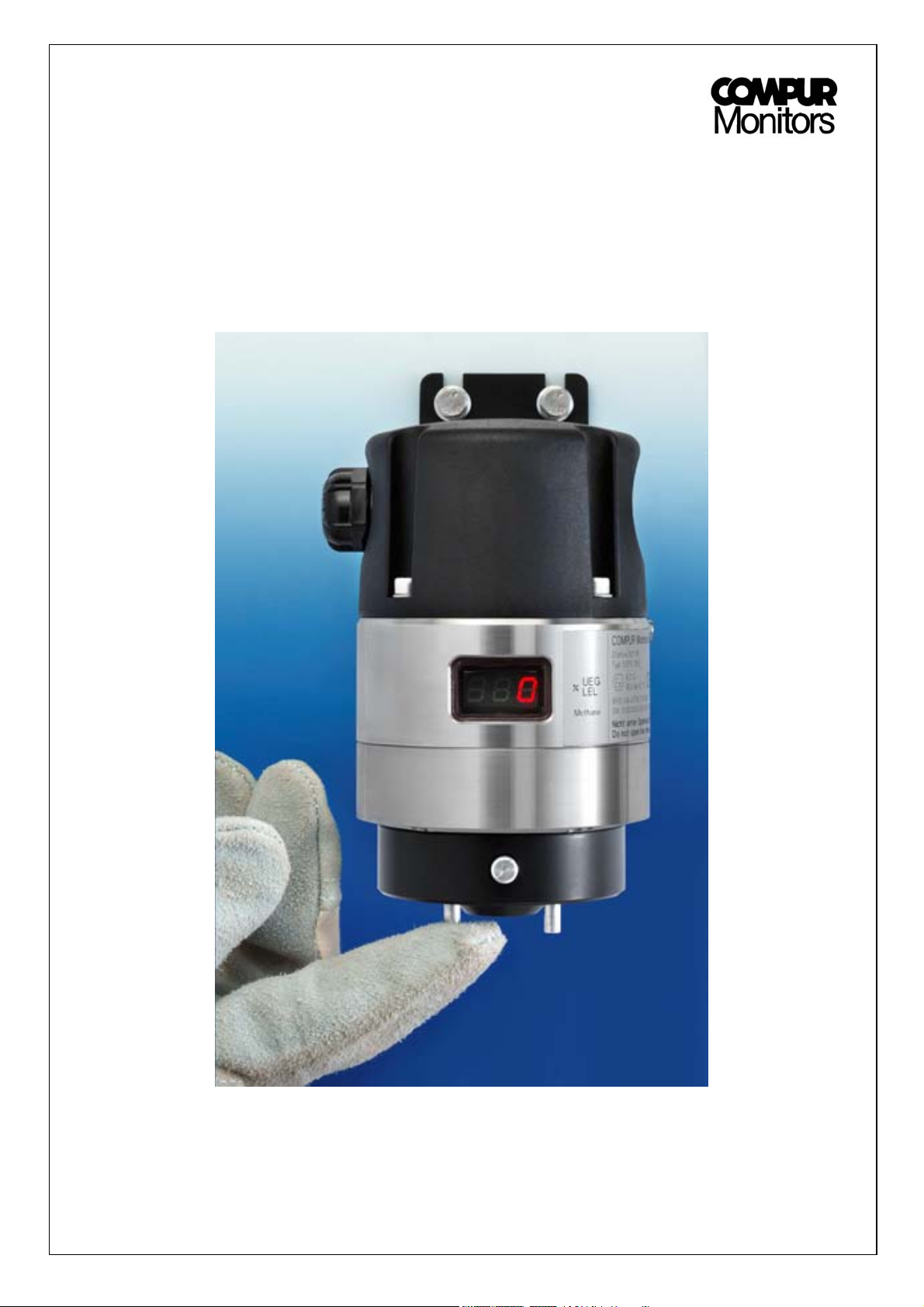
Statox 501 IR
Statox 501 IR Sensor Head
Manuel / Manual
Page 2

Statox 501 IR Statox 501 IR Sensor Head
Manuel
Contenu
1. Instructions de sécurité 1. Safety instructions
2. Construction et fonctions 2. Construction and function
3. Montage et connections 3. Mounting and connections
3.1 Montage murale 3.1 Wall mounting
3.2 Branchement du transmetteur 3.2 Connecting the transmitter
3.3 Raccordement au module de contrôle Statox 501 3.3 Connection to the Statox 501 control modul
3.4 Raccordement à tout autre contrôleur ou PCS 3.4 Connection to any other controller or a PCS
4. Démarrage et Menu 4. Start-up and password menu
4.1 Réglage du zéro et du span avec un gaz étalon 4.1 Zero and span adjustment with gas
4.2 Réglage de l’amplificateur 4.2 Amplifier adjustment
4.3 Test des sorties 4-20 mA 4.3 Testing the analog output
4.4 Choix du signal de sortie en cas de mode service 4.4 Selection of the output signal in the service mode
4.5 Programmation du gaz mesuré 4.5 Programming the measuring gas
5. Remplacement du capteur 5. Sensor replacement
6. Maintenance
7. Accessoires et pièces détachées
8. Etats et messages d’erreur
8.1 Messages d’état de fonctionnement 8.1 Status messages
8.2 Messages d’erreur 8.2 Error messages
9. Caractéristiques techniques
10. Déclaration de conformité CE
6. Maintenance
7. Accessories and spare parts
8. Status and error messages
9. Technical data
10. CE-Declaration of conformity
Manual
Contents
*************** ***************
1. Instructions de sécurité 1. Safety instructions
Le Statox 501 IR est un transmetteur de sécurité
intrinsèque de groupe II catégorie 2. Il mesure la
concentration des gaz combustibles at des vapeurs
d’hydrocarbures. Il possède un grand niveau de sécurité
et peut être installé en zone 1 et 2
Merci de suivre les instructions suivantes:
• Le transmetteur est un appareil de sécurité
intrinsèque. Toutes les règles concernant l’installation
d’équipement anti-déflagrant (ex DIN EN 60079-14,
sections 6, 9 et 10 ) devront être respectées.
• Le transmetteur doit exclusivement fonctionner avec
une tension de 18-29VDC (sécurité en très basse
tension).
• Le transmetteur ne doit pas être ouvert tant que son
alimentation n’est pas débranchée.
• Seulement les pièces détachées et accessoires de
COMPUR doivent être utilisés..
• Toute les vis doivent être sérées avant de brancher le
transmetteur.
• Faire fonctionner le transmetteur avec un boîtier
endommagé n’est pas sûre.
• Le transmeteur ne doit pas fonctionner dans un
environnement en dehors des spécifications.
• Le certificat de conformité ne comporte pas de test de
performance.
• Tous les avertissements ci-dessus doivent être
observés. Une installation ou le raccordement
incorrecte annulera la protection anti-déflagrante et
sera ainsi dangereux pour la vie et les biens.
The Statox 501 IR is an explosion proof transmitter rated
for use in group II category 2 areas. It measures the
concentration of combustible gases and the vapors of
hydrocarbons. It has a high degree of safety and can be
installed in zone 1 and 2.
Please observe the following instructions:
• The transmitter is an explosion proof device. All
regulations regarding installation of explosion proof
equipment (i. e. DIN EN 60079-14, section 6, 9 and 10)
should be observed.
• The transmitter must be exclusively operated with 18 –
29 V DC (safety extra-low voltage).
• The transmitter may not be opened unless it is
disconnected from the power supply.
• Only original Compur spare parts and accessories must
be used.
• All screws must be tightened before operating the
transmitter.
• Operating the transmitter with a damaged housing is
unsafe.
• The transmitter must not be operated in any
environment outside of the approval rating.
• The certificate of conformity does not include a
performance approval.
• All of the above warnings must be observed. Incorrect
installation or connection will void the explosion proof
rating and thus be dangerous to life and assets.
Page 3
2. Construction et fonctions 2. Construction and Function
1
11
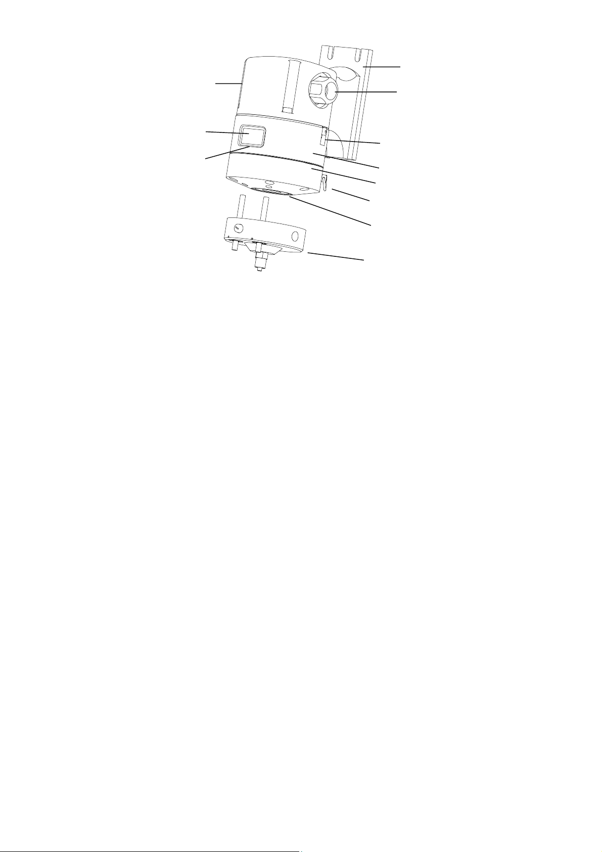
1 Support
2 Presse etoupe
3 Borne au sol
4 Compartiment électronique
avec plaque signalétique: type,
n° de série, date de fabrication
5 Compartiment du capteur
6 Anneau pour sangle
7 Protection pour éclaboussure
8 Adaptateur de calibartion
9 LED de service
10 Affichage
11 Vis bouchon
10
9
R
↵
Le Statox 501 IR détecte les gaz combustibles (Méthane,
Butane) et les vapeurs (Méthanol, Toluène) dans une
gamme de 0 à 100 % LIE. La tête de détection est un
transmetteur 4-20 mA. Il peut être utilisé avec le module
de contrôle dédié Statox 501 ou avec tout autre système
de contrôle de procédé.
Support
Le support et boîtier terminal sont fabriqués en polyamide
renforcé de fibres conductrices. Il est de sécurité accrue
pour l’utilisation dans des environnements explosifs
(EExe), et est livré avec un presse étoupe (M20) et une
vis bouchon de l’autre côté. Un second presse étoupe
peut remplacer cette vis en option.
Boîtier du tranmetteur
Le boîtier en acier inoxydable du transmetteur se
compose d’une partie supérieure et inférieure antidéflagrantes. Il contient l’électronique, le capteur et
l’affichage LED à trois chiffres. L’orifice de la sonde est
protégé contre les dommages de l’eau par un filtre antiéclaboussure.
Capteur
Le capteur est un capteur NDIR qui consiste en un source
de lumière et deux photo détecteurs. La longueur d’onde
de mesure est calibré sur la longueur d’onde d’absorption
de la liaison C-H des hydrocarbures (3,4 µm). Plus il y a
de molécules de gaz dans le faisceau de lumière (plus la
concentration du gaz est grande) plus la lumière infra
rouge sera absorbée. Le détecteur de référence travaille
à une longueur d’onde différente à laquelle aucune
absorption n’aura lieu. Cela permet ainsi de compenser
les effets de la poussière, de l’humidité ou des variations
de l’intensité de la source lumineuse.
Adaptateur de calibration
L’adaptateur optionnel de calibration se branche sur la
partie inférieure du détecteur. Il est équipé d’un raccord
pour tube 4-6mm et de deux boutons magnétiques. Ces
boutons poussoirs permettent d’accéder au menu, pour la
calibration et le réglage des différents paramètres.
L’utilisation avec la sortie de gaz optionnelle permet de
travailler avec un débit. Pour prévenir toute fuite, le joint
ne doit pas être endommagé et toujours être fixé
solidement dans sa nervure. L’adaptateur peut être fixé
de manière permanente au détecteur avec deux vis.
2
1 Mounting bracket
2 Cable gland
3 Grounding terminal
3
4
5
6
7
8
4 Electronic compartment
with type plate,
serial number / date code
5 Sensor compartment
6 Ring for holding strap
7 Splash guard
8 Calibration adapter
9 Service LED
10 Display
11 Plug screw
The Statox 501 IR detects combustible gases (e.g.
Methane, Butane) as well as vapors (e.g. Toluene,
Methanol) in the range of 0 - 100% LEL. The sensor head
is a 4 - 20 mA transmitter. It can be used in combination
with the dedicated Statox 501 controller or any process
control system.
Mounting bracket
The mounting bracket / terminal box is made of conductive
fiber re-enforced polyamide. It features increased safety for
use in explosive environments (EEx e), and comes with one
cable gland (M 20) and one screw plug on the other side.
An optional second cable gland can replace this.
Transmitter Housing
The stainless steel transmitter housing consists of a top
and bottom part, which are rated as explosion proof. It
contains the electronics, the sensor and the three-digit LED
display. The sensor orifice is protected from water damage
by a disposable splash guard.
Sensor
The sensor is a NDIR sensor consisting of a light source
and two photo detectors. The measuring wavelength is
calibrated to the absorption wavelength of the C-H bond of
hydrocarbons (3,4 µm). The more gas molecules are in the
way of the light beam (i.e. the higher the gas concentration
is) the more infrared light will be absorbed. The reference
detector works at a wavelength in which no absorption
takes place to compensate for dust, humidity and variations
of light source intensity.
Calibration adapter
The optional calibration adapter can be connected to the
bottom side of the sensor head. It has a gas intake for a 4 x
6 mm tube and two magnetic pins. The pins operate Hall
sensors allowing you to access the password-protected
menu, for calibration and setting parameters.
Used with an optional gas outlet, it can serve as a gas
adapter for flow applications. To avoid leaks, the integrated
O-ring must be undamaged and always be fitted securely in
its groove. The calibration adapter can permanently be
fixed to the transmitter with 2 screws.
Page 4
3. Montage et connections
3. Mounting and Connections
3.1 Montage murale
Utiliser le plan de forage inclus pour placer les trous du
support. Enlever le support du transmetteur.
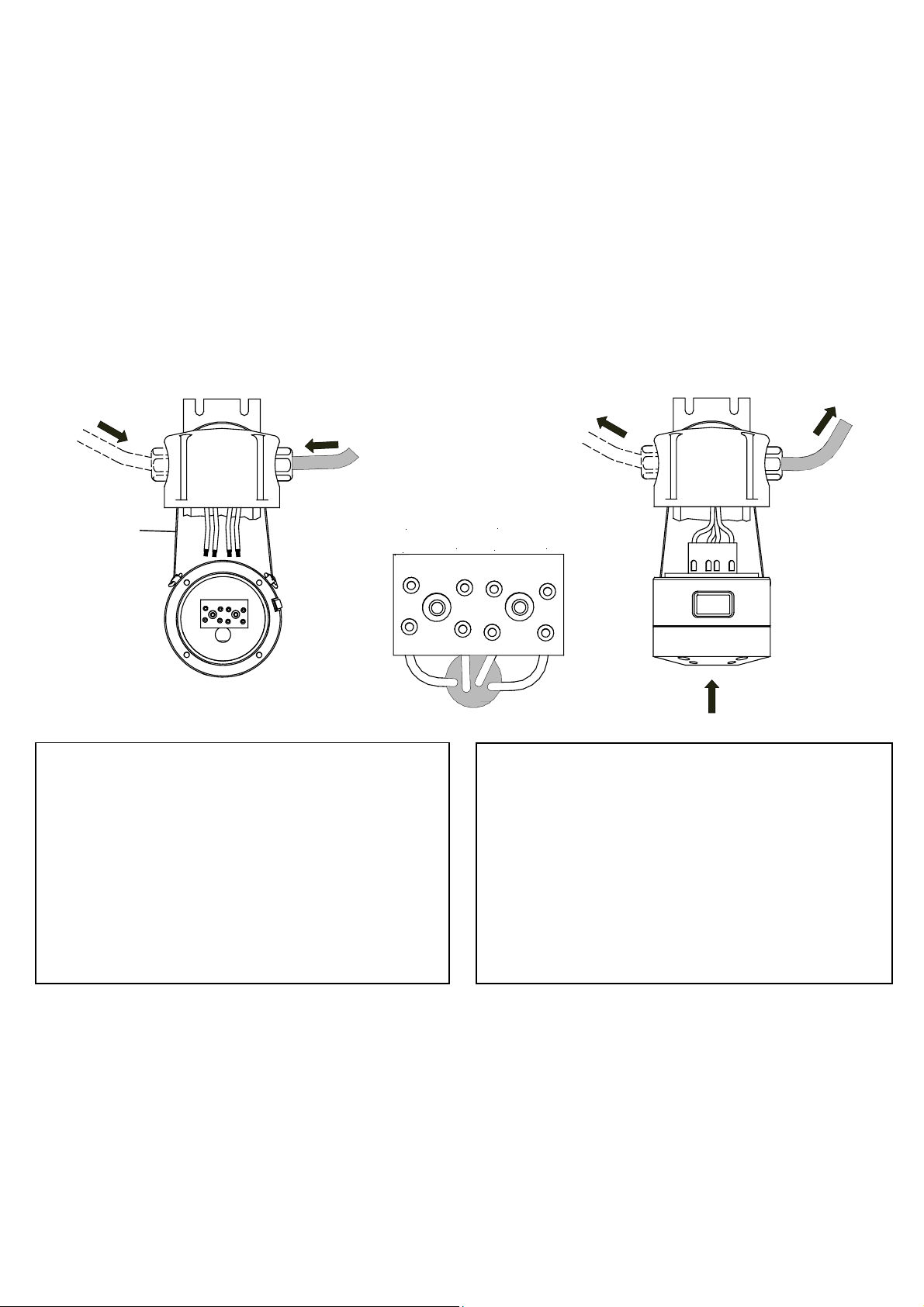
3.2 Branchement du transmetteur 3.2 Connecting the Transmitter
Reliez la sangle aux anneaux situés à l’arrière du
détecteur afin de pouvoir le maintenir au support. Ceci
permettra de relier les fils sans avoir à tenir la partie
inférieure. Tirez le câble par le presse étoupe. Branchez
les fils aux bornes selon le schéma. Si deux câbles
séparés pour l’alimentation et le signal de sortie doivent
être utilisés, remplacez la vis bouchon par un deuxième
presse étoupe (Art. 561051).
Rassemblez le transmetteur et le boîtier inférieur,
maintenir le câble tendu en le tirant de l’extérieur pendant
le montage. Serrez les vis et le presse étoupe.
3.1 Wall Mounting
Use the enclosed drilling plan to position the mounting
holes. Remove the mounting bracket / terminal box from
the transmitter. Fasten it to the wall with 6 mm screws.
Connect the holding strap to the rings located on the back
side of the transmitter, allowing it to hang on the mounting
bracket. This will conveniently hold the transmitter in place
while connecting the wires. Pull the cable through the
gland. Connect the wires to the terminals according to the
schematics. If two separate cables for signal and power
supply are to be used, replace the plug screw with a
second cable gland (part. # 561051).
Couple the transmitter to the bottom side of the terminal
box, keeping the cable straight by pulling it outward while
mounting. Fasten screws and cable gland(s).
Sangle
Holding strap
1
Note importante:
• Utilisez uniquement des câbles protégés d’un diamètre
extérieur de 8 à 13 mm, et d’une section > 0.75mm
Mettre le bouclier à la terre seulement en salle de
contrôle.
• Le joint doit être propre et intact, et doit rester dans sa
fente.
• Serrez fortement à la main chacun des 4 boulons à
têtes creuses. Couple recommandé de 1 Nm.
• Aucun espace ne doit être visible entre le transmetteur
et la boîte terminale..
3.3 Raccordement au module de contrôle Statox
501
Lisez et observez le manuel d’utilisation du module de
contrôle Statox 501 !
Avant de relier le transmetteur, choisissez le programme
46 sur le contrôleur. Reliez le câble du signal (4-20mA)
aux bornes 4 (+) et 11 (-) du module de contrôle (voir
image ci-dessous).
24V DC
+
2
2
4-20mA
-
+
Important note
• Use only shielded cable with an outer diameter of 8 - 13
.
• The O - ring must be clean and intact. It must stay in its
• Fasten all 4 Allen screws hand tight. Recommended
• No gap must be visible between the transmitter and
3.3 Connection to the Statox 501 Control Module
Read and observe the operations manual of the Statox 501
controller!
Before connecting the transmitter, select program 46.
Connect the signal cable (4 - 20 mA) to terminals 4(+) and
11(-) of the control module (see picture).
-
mm, sectional area > 0,75 mm
ground only in the control room.
groove.
torque 1 Nm.
terminal box.
3
2
. Connect the shield to
Page 5

Terminaux sur module de contrôle Statox 501 / Terminals Controlmodule Statox 501
3.4 Raccordement à tout autre contrôleur ou PCS 3.4 Connection to any other Controller or a PCS
Si vous reliez le Statox 501 IR à tout autre dispositif de
commande ou PCS, merci d’observer les caractéristiques
techniques au chapitre 9.
If you connect the Statox 501 IR to any other control device
or PCS, observe the technical data in chapter 9.
4. Démarrage et Menu 4. Start-up and Password Menu
Après avoir été relié à l’alimentation 24 V, le Statox 501
IR affiche la version du logiciel et le code du gaz (liste
4.5). Après le préchauffage, il entre dans le mode de
détection et affiche la concentration du gaz en % LIE.
Pour accéder au menu utilisateur, reliez l’adaptateur de
calibration au détecteur. Il y a deux boutons qui peuvent
être utilisés sur l’adaptateur. Le bouton Enter ↵ vous
permet de vous diriger vers le prochain point du menu ou
de sélectionner le code menu. Le bouton Reset R vous
ramène toujours au mode de mesure.
Appuyer sur le bouton Enter ↵ pour accéder au menu. Le
premier chiffre commencera à alterner. Choisissez le
code désiré en pressant le bouton enter ↵ dès que le
premier chiffre est correcte. Le second chiffre
commencera à alterner de la même manière. Choisissez
le second chiffre en poussant le bouton enter ↵ quand le
code sera correcte. Un diagramme illustré du menu est
disponible dans ce document..
4.1 Réglage du zéro et du span avec un gaz étalon 4.1 Zero and Span Adjustment
Sélectionner le menu 11.
Le transmetteur est pré calibré en usine. Avant d’effectuer
une calibration, laissez stabiliser le transmetteur au moins
une heure. Après avoir lancer le programme de
calibration, le zéro sera ajusté. Pendant ce processus
“000” clignotera sur l’affichage.
Le mise à zéro doit absolument être effectuée dans une
atmosphère propre. Si vous êtes incertain de
l’environnement, utilisez de l’air synthétique. Pour
retourner au mode de mesure et éviter la calibration,
appuyez sur le bouton Reset. En appuyant sur le bouton
enter ↵
utiliser doit se situer entre 30 et 70% de la LIE. Branchez
le gaz étalon au raccord de l’adaptateur et commencez la
procédure de calibration en apuyant sur le bouton enter ↵
Pendant la calibration “Go” s’affiche à l’écran. Après un
certain temps “Go” commence à clignoter, cela indique
que le gaz étalon a été détecté. Quand la calibration est
réussie, l’affichage indique Con. Jusqu’à cette affichage
aucune nouvelle donnée n’est enregistrée. En appuyant
sur le bouton Reset, vous retournerez dans le mode de
mesure et le transmetteur utilisera les anciennes données
de calibration.
La dernière étape pour la calibration est d’entrer la
concentration du gaz étalon. La dernière valeur utilisée
s’affiche à l’écran. Si aucun changement est nécessaire,
appuyez sur le bouton enter. Dès que le transmetteur est
vous commencez la calibration. Le gaz étalon à
After being connected to the 24 V power supply, the Statox
501 IR will display the software index and then the gas
code (see list 4.5). After warm up it will go into the detection
mode and start displaying the gas concentration.
To access the user menu, connect the calibration adapter
to the sensor head. There are 2 keys that can be used on
the calibration adapter. Pressing the Enter button ↵ will
bring you to the next menu point or selects a menu code. R
(Reset) always brings you back into the measuring mode.
Push the Enter button ↵ to access the password menu. The
first digit will start alternating. Select the desired code by
pushing the Enter button when the correct first digit
appears. The second digit will start alternating in the same
way. Select the secondary code by pushing the Enter
button when the correct digit arrives. An illustrated menu
diagram is available in this document.
Select code 11.
The transmitter is pre-calibrated. Before starting a
calibration allow at least 1 hour to stabilize. After initiating
the calibration program, the zero will be adjusted. During
this process the display will flash “000”.
Zeroing must be done in a clean atmosphere. If you are
unsure about the environment, use synthetic air. To return
to the measuring mode and avoid the calibration procedure,
press the reset button. Pushing Enter ↵ button starts a gas
calibration. Span gas with a concentration from 30 to 70%
LEL should be used. Connect the gas to the intake of the
calibration adapter and start the procedure by pushing the
Enter ↵ button.
During a calibration “Go” will appear on the display. After a
while “Go” will start flashing, indicating that the calibration
gas has been detected. When the calibration has been
successfully finished, the display will show Con. Up to this
point no new data has been stored. Pushing the Reset
button will return to the measuring mode and the transmitter
will use the previous calibration data.
The final step for calibration is entering the span gas
concentration. The last concentration used will appear on
the display. If no change is needed, push the Enter button.
Once the instrument has returned to the normal detection
mode, it verifies the calibration by displaying the actual gas
concentration.
Page 6

retourné en mode de détection normal, il vérifie la
calibration en affichant la concentration actuelle du gaz
mesuré.
4.2 Réglage de l’amplificateur 4.2 Amplifier Adjustment
Sélectionner le menu 44.
Ce dispositif est utilisé pour obtenir la plus grande
précision après le remplacement du capteur, en ajustant
automatiquement le gain de l’amplificateur. Après cela, un
ajustement du zéro et une calibration avec un gaz étalon
sont nécessaire. Si vous n’êtes pas sûre que l’air ambiant
est propre, utilisez de l’air synthetique. Ceci sera indiqué
par CAL clignotant sur l’afficheur (voir 4.1).
4.3 Test des sorties 4-20 mA 4.3 Testing the analog output
Sélectionner le menu 12.
Cette fonction permet à l’utilisateur de vérifier la sortie 4 20 mA. Vous pouvez simuler un signal de 4, 12 ou 20mA
en appuyant sur le bouton Enter. Vous pouvez retourner
au mode de mesure à tout moment en pressant le bouton
Reset.
Attention: Neutralisez les dispositifs périphériques
d’alarme afin d’éviter de fausses alarmes!
4.4 Choix du signal de sortie en cas de mode
service
Sélectionner le menu 13.
Choisir la valeur du courantde sortie que vous désirez en
mode de service. Par défaut c’est la valeur de 2 mA.
4.5 Programmation du gaz mesuré 4.5 Programming the measuring gas
Pour programmer le gaz, entrer dans le menu 45.
Dans ce menu vous pouvez modifier la configuration
sortie d’usine. Chaque fois que vous changez le type de
gaz, une calibration vous sera demandée. Ceci est
visualisé par le signe CAL clignotant à l’écran. Assurez
vous, avant d’entrer dans ce menu, d’avoir tous les
accessoires nécessaires pour réaliser une calibration.
Liste des gaz:
• 1 Méthane
• 2 Propane
• 3 n-Butane
• 4 n-Pentane
• 5 c-Pentane
• 6 n-Hexane
• 7 Methanol
• 8 Propene
• 9 2-Propanol
Select code 44.
This feature is used to obtain the highest accuracy after
sensor replacement, by automatically adjusting the
amplifier gain. After this zero adjustment and a gas
calibration is mandatory. If you are not sure that ambient air
is clean, use synthetic air. This will be indicated by CAL
flashing on the display (see 4.1).
Select code 12.
This function allows the user to test the 4 - 20 mA output.
You can simulate a 4, 12, or 20 mA signal by pressing the
Enter button. Return to the measuring mode at any time by
pushing the Reset button.
Caution: Disable peripheral alarm devices to avoid false
alarms!
4.4 Selection of the output signal in the service
mode
Select code 13.
Select the current value to which the analog output shall be
set when in the service mode. Default setting is 2 mA.
To program the gas, enter menu 45.
In this menu you can alter the ex works setting. Whenever
you change the gas a new calibration is mandatory. This is
visualised by CAL flashing on the display. Make sure to
enter this menu only if you have everything on hand you
need for a gas calibration.
Gas list:
• 1 Methane
• 2 Propane
• 3 n-Butane
• 4 n-Pentane
• 5 c-Pentane
• 6 n-Hexane
• 7 Methanol
• 8 Propene
• 9 2-Propanol
5. Remplacement du capteur 5. Sensor Replacement
Débranchez l’alimentation du transmetteur. Placer la
sangle autour du support et l’attacher aux anneaux sur les
cotés afin de maintenir en place le compartiment du
capteur. Enlevez les 6 vis de la partie inférieure et
débranchez la sonde. Branchez le nouveau capteur et
rattachez le boîtier inférieur avec les anneaux sur l’arrière
Serrez les vis seulement à la force des mains. Le couple
recommandé est 3 - 3,5 Nm. Aucun espace ne doit être
visible entre les deux pièces. Chacune des 6 vis doit être
utilisée!
A la suite du remplacement du capteur, un ajustement du
gain (4.2) et une calibration avec un gaz étalon (4.1)
doivent être effectués!
Disconnect the transmitter from the power supply. Hold it in
place by fastening the holding strap to the rings on the
transmitters backside and hanging it around the mounting
bracket. Remove the 6 screws from the bottom part and
disconnect it. Plug the new sensor in and reattach the
bottom housing, with rings on the backside.
Fasten the screws only hand tight. The recommended
torque is 3 - 3,5 Nm. No gap must be visible between the
two parts. All 6 screws must be used.
Following the sensor replacement, a gain adjustment (4.2)
and gas calibration (4.1) must be performed.
Page 7

↵
↵
↵
↵
↵
↵
↵
↵
↵
↵
n
↵
↵
↵
n
000
4
0
Con
t
↵
4
0
12
2
1.1.1
11
t
4
PAS
0
6
S
6o
0
-
4
1
↵
CAL
4.
4
Ab
CAL
Diagramme du menu / Menu diagramm
-1
1.
CAL
00
6A
5
do
Version du
software
Code du gaz
gas code
Mode de mesure
Measuring mode
Menu
Password menu
1
1S
2
13
Menucodes
1o
2
do
Étape suivante
next step
retour au mode mesure
R
back to measuring mode
60 s timeout
Page 8

0
0
r
r
0
S
t
t
6o
S
n
n
Ab6
000
PAS
t
Iot
o
S
don
n
6
6. Maintenance
• Inspection visuel du boîtier pour être sûre qu’il est
intacte et que le filtre est propre
• Ajustement du zéro : seulement si besoin
• Calibration avec gaz étalon: l’intervale dépends des
régles locales
• Ajustement du gain: seulement si besoin et après
chaque remplacement du capteur.
7. Accessoires et pièces détachées
• 561053 Capteur IR
• 561051 Presse étoupe
• 561055 Filtre à éclaboussure
• 561057 Set de joint
• 562031 Adaptateur de calibration
• 561059 Adaptateur de 6mm pour sortie du gaz
8. Etats et messages d’erreur
8.1 Messages d’état de fonctionnement 8.1 Status Messages
• La LED jaune clignote tant que le transmetteur est en
mode service.
• La sortie analogique est fixée à 2 ou 4 mA.
Code d’erreur
Ab
Ajustement du gain
en cours
Description
Remarque Error code Description Remark
Optimisation du gain
6. Maintenance
• Visual inspection of the housing to make sure it is intact
and the splash guard is clean.
• Zero adjustment: Only if needed.
• Gas calibration: Interval according to local regulations.
• Gain adjustment: Only if needed and after sensor
replacement.
7. Accessories and Spare Parts
• 561053 IR-Sensor
• 561051 Cable gland
• 561055 Splash guard
• 561057 O-Ring-Set
• 562031 Calibration adapter
• 561059 6mm-Adapter gas outlet
8. Status and Error Messages
• The yellow LED will flash while the transmitter is in the
service mode.
• The analog output is set to 2 resp. 4 mA.
Gain adjustment in
process
Optimizing gain
CAL
Entrer la
Co
PA
6A
6
IS
Caliration
concentration du
gaz étalon
Sélection du gaz
Effectué
Ouvrir la bouteille
de gaz
Clignote losque le
gaz est détecté
Sortie analogique
en mode service
Test de la sortie
analogique
Acces au menu
Pendant la calibration
et le zéro
Dernière
concentration affiché
Départ de la
calibration
2 mA ou 4 mA
4, 12, 20 mA
CAL
Co
PA
do
6A
Io
IS
PA
Gas calibration
startet
Enter span gas
concentration
Gas selection
Done
Turn gas on
When flashing span
gas is detected
Current output in the
service mode
Current output test 4, 12, 20 mA
Access menu
During gas
calibration and
zeroing
Concentration
used last time on
display
Start gas
calibration
2 mA or 4 mA
Ajustement du zéro
Clignote lorsque la
10
pleine échelle est
dépassé
Pendant la calibration
ou après un
ajustement du gain
00
Flashing when the
10
Zero adjustment
measuring range is
exceeded
During gas
calibration or after
gain adjustment
Page 9

8.2 Codes d’erreur 8.2 Error Codes
• Pour retourner au mode de mesure à partir d’un code
d’erreur, presser le bouton Reset.
• Si une erreur est s’est produite, la LED jaune
s’allumera .
• La sortie analogique sera de 0 mA dans le cas d’une
erreur fatale, autrement la sortie sera au choix à 2 ou
4 mA pour toute autre erreur.
Code d’ereur Problème Raison potentielle Solution
• To go from an error code back to the measuring mode,
press the Reset button.
• If an error has occurred, the yellow LED will go on.
• The analog output will be set to 0 mA in case of a fatal
error, otherwise the output will be 2 or 4 mA for all other
errors.
Défaut du capteur
r
r
r
apteur Zéro négatif - Dérive du zéro
r
Erruer d’EEPROM - Problème de hardware
r
r
CAL
CAL
Surcharge de
l’amplificateur
Timeout pendant la
caliration
Le zéro ne peut être
effectué
Clignote: Demande de
calibration
Clignote en alternance
avec la valeur mesurée
- Manque le capteur
- Capteur défectueux
- Signal du capteur trop haut
- Erreur de hardware
- Pas de Gaz Etalon
- Concentration du Gaz Et trop faible
- Le capteur a perdu en sensibilité
- Présence de gaz pendant
l’ajustement du zéro
- La calbration n’a pas été validée
après l’ajustement de l’amplification
(4.2) ou changement du gaz à
mesurer (4.5)
- La calibration n’a pas été validée
après le timeout
Erreur fatale!
Remplacer le capteur.
Erreur fatale!
Ajuster le gain et calibrer. Si le
détecteur ne fonctionne pas
contacter l’usine
L’appareil conserve sa calibration
précédente. Ouvrir le gaz, utiliser le
gaz approprié. Remplacer le capteur
Erreur fatale!
Ajuster le zéro.
Erreur fatale!
Contacter l’usine
L’appareil conserve sa calibration
précédente. Refaire le zéro en
utilisant de l’ai synthétique
Erreur fatale!
Faire une calibration (4.1).
Faire une calibration (4.1).
Error code Problem Potential reason Trouble shooting
Sensor defective
r
r
Timeout during calibration
r
Negative zero - Zero drift
r
EEProm Error - Hardware problem
r
Zero could not be attained
r
CAL
CAL
Amplifier overload
Flashing: Calibration
reqest
flashing in change with
actual measuring value
- Sensor missing
- Sensor defective
- Sensor signal too high
- Hardware error
- No span gas
- Span gas concentration too low
- Sensor has lost sensitivity
- Gas present during zero
adjustment
- no successful calibration after
amplifier adjustment (4.2) or
altering the measuring gas (4.5)
- no successful calibration after
timeout
Fatal Error!
Replace sensor.
Fatal Error!
Adjust gain and calibrate. If it still
does not function, contact the
factory.
Continuous operation with origin
calibration data. Turn gas on, use
proper gas. Replace sensor.
Fatal Error!
Adjust zero.
Fatal Error!
Contact factory.
Continuous operation with origin
calibration data. Repeat zero, use
synthetic air.
Fatal Error!
Calibrate (see 4.1).
Calibrate (see 4.1).
Page 10

9. Caratéristiques techniques
9. Technical Data
• Nom du produit Transmetteur Statox 501 IR • Product name Statox 501 IR Transmitter
• Type 5370 063
• Fabricant COMPUR Monitors, Munich
• Echelle de mesure 0 - 100% UEG
• Principe de mesure NDIR à 2 voies
• Limite de détection 3% LIE Méthane
• Affichage LED, trois digites
• Temps de réponse CH
t50 < 10s, t90 < 25s
4
• Précision (pleine échelle) < ± 2% LIE
• Temps de chauffe 20 s
• Spécifications atteintes après 30 min
• Température d’utilisation -20°C à +44°C
• Température de stockage -20°C à +60°C
• Humidité 0 - 99% HR.
• Pression 800 - 1100 hPa,
Déviation < ± 0,1% / hPa
• Explosionsschutz EEx de IIC T5
• Class instrument II 2 G
• Certification BVS 04 ATEX E 006 X
• Tension
24VDC (18-29VDC)
• Puissance 1 Watt
• Courant max. 80 mA à 24 V
• Sorties 4-20 mA,Rmax 220 Ohm
• Demande de service LED jaune clignote,
Sortie 2 ou 4mA
• Erreu du système LED jaune allumée,
Sortie 2 ou 4mA,
erreur fatale 0 mA
• Protection EN 60529 IP 67
• Dimensions (LxlxP) 150x120x120mm
• Instruction d’installation Capteur vers le bas et
position droite à ± 90°
• Poids 3,1 kg
• Matériaux PA et acier 1.4305
• EMV EN 50270
• Performance approuvée EN 61779-1 et -4
• Type 5370 063
• Manufacturer COMPUR Monitors, Munich
• Measuring Range 0 - 100% LEL
• Measuring principle 2-channel NDIR
• Detectable limit 3% LEL Methane
• Display LED, three digit
• Response time, i.e. CH
t50 < 10s, t90 < 25s
4
• Accuracy (full scale) < ± 2% LEL at RT
• Warm up time 20 s
• Specifications reached after 30 min
• Temperature -20°C to +44°C (-4 to +112°F)
• Storage Temperature -20°C to +60°C (-4 to +140°F)
• Humidity 0 - 99% r.F.
• Pressure range 800 - 1100 hPa,
Deviation < ± 0,1% / hPa
• Approval EEx de IIC T5
• Instrument class II 2 G
• Certificate BVS 04 ATEX E 006 X
• Voltage 24VDC (18-29VDC)
• Power 1 Watt
• Current max. 80 mA at 24 V
• Output 4-20 mA, max. load 220 Ohm
• Service request yellow LED flashing,
output 2 or 4mA
• System failure yellow LED on,
output 2 or 4mA,
fatal error 0 mA
• Protection class EN 60529 IP 67
• Dimensions (HxWxD) ca. 150x120x120mm
(5,9x4,7x4,7in)
• Installation instructions upright position ± 90° ,
sensor downwards
• Weight ca. 3,1 kg (6,8 pound)
• Material PA and Steel 1.4305
• EMV according to EN 50270
• Performance approval EN 61779-1 and -4
Les caractéristiques techniques de ce produit peuvent faire l’objet de
modifications sans préavis. Compur Monitors n’a pas de contrôle sur
l’utilisation de ses produits. Pour cette raison, il est de la responsabilité
de l’utilisateur de se renseigner sur nos produits afin de déterminer s’ils
sont adaptés à l’utilisation, à l’application et aux conditions envisagés.
Toutes les informations fournies ne font pas l’objet d’une garantie.
Compur Monitors se dégage de toute responsabilité pour toute utilisation
non conforme ou incorrecte, négligence, ou autre de ses produits et de
ses informations. Tout élément ou recommandation non contenus dans
ce document ne sont pas autorisés et ne peuvent en aucun cas
impliquer la responsabilité de Compur Monitors. Aucun élément décrit
dans ce manuel ne peut être assimilé à une recommandation
d’utilisation de produits qui sont sous la protection d’un brevet. Les
appareils sont fabriqués par Compur Monitors GmbH & Co. KG, Munich.
Les conditions générales de vente et de service de Compur Monitors
GmbH & Co. KG sont applicables.
Specifications are subject to change without notice, and are provided only for
comparison of products. The conditions, under which our products are used,
are beyond our control. Therefore, the user must fully test our products and/or
information to determine suitability for any intended use, application, condition
or situation. All information is given without warranty or guarantee. Compur
Monitors disclaims any liability, negligence or otherwise, incurred in
connection with the use of the products and information. Any statement or
recommendation not contained herein is unauthorized and shall not bind
Compur Monitors. Nothing herein shall be construed as a recommendation to
use any product in conflict with patents covering any material or device or its
use. No licence is implied or in fact granted under the claims of any patent.
Instruments are manufactured by Compur Monitors GmbH & Co. KG, Munich.
The General Conditions of Supply and Service of Compur Monitors GmbH &
Co. KG are applicable.
Page 11

Compur Monitors GmbH & Co. KG
Weißenseestraße 101
D-81539 München
Phone: ++49 89 620 38-0
Fax: ++49 89 620 38-184
E-Mail: compurmonitors@t-online.de
Internet: www.compur.com
USA, Canada, Mexico:
Compur Monitors Inc.
100 East Nasa Road One, Suite 308
USA-Webster, TX 77598
Phone: ++1 281 338 78 85
Fax: ++1 281 557 79 11
E-Mail: USCompur@compur.us
Belgium, Netherlands, Luxemburg:
Compur Monitors B.V.
De Veldoven 49
NL-3342 GR Hendrik Ido Ambacht
Phone: ++31 78 682 05 37
Fax: ++31 78 682 19 36
E-Mail: info@compur.nl
Internet: www.compur.nl
France:
Compur Monitors SARL
155 Avenue du Général de Gaulle
F-92140 Clamart
Phone: ++33 1 45 37 89 51
E-Mail: compur@compur.fr
Internet: www.compur.fr
5370 063 999 04 00 / 10.05 561883
 Loading...