

Page 1

Page 2

i
VECTOR
Copyright © 2012 Compulite Systems (2000) Ltd. All rights reserved.
This documentation is delivered subject to the following conditions and
restrictions:
This document is protected by copyright and distributed under licenses
restricting its use, copying, distribution and decompilation. No part of this
product or document may be reproduced in any form by any means without
the prior express written authorization of Compulite and its licensors (if any).
The content of this document is furnished for informational use only and is
subject to change without notice. Compulite assumes no responsibility or
liability for errors or inaccuracies that may appear in this book.
Document Revision History
Document Version 4.2 September 2012
Document Version 4.1 December 2010
Document Version 4.0 February 2010
Document Version 3.0 November 2008
This document was set up for two sided printing. So conserve trees and print on both
sides
Page 3

iii
Table of Contents
Chapter 1: Setting Up and Overview . . . . . . . . . . . . . . . . . . . . . . . . . . 3
Setting up Vector . . . . . . . . . . . . . . . . . . . . . . . . . . . . . . . . . . . . . 4
Vector Violet - Configuring a DVI Monitor . . . . . . . . . . . . . . . . . . . . 5
Vector operation modes and programming syntax . . . . . . . . . . . . . . 7
Tracking mode operation . . . . . . . . . . . . . . . . . . . . . . . . . . . . . 7
Compulite mode operation . . . . . . . . . . . . . . . . . . . . . . . . . . . . 7
Programming syntax . . . . . . . . . . . . . . . . . . . . . . . . . . . . . . . . 8
Basic display layouts . . . . . . . . . . . . . . . . . . . . . . . . . . . . . . . . . . 9
Screen elements . . . . . . . . . . . . . . . . . . . . . . . . . . . . . . . . . . 10
Pointing and navigating . . . . . . . . . . . . . . . . . . . . . . . . . . . . . . . 12
Using the trackball . . . . . . . . . . . . . . . . . . . . . . . . . . . . . . . . . 12
Scrolling and navigating displays . . . . . . . . . . . . . . . . . . . . . . . 12
Using console keys in window mode . . . . . . . . . . . . . . . . . . . . 13
Setting up displays . . . . . . . . . . . . . . . . . . . . . . . . . . . . . . . . . . . 14
Opening new windows . . . . . . . . . . . . . . . . . . . . . . . . . . . . . . 14
Opening new view panes . . . . . . . . . . . . . . . . . . . . . . . . . . . . 14
Setting Up Soft Keys . . . . . . . . . . . . . . . . . . . . . . . . . . . . . . . . . 16
Defining soft keys . . . . . . . . . . . . . . . . . . . . . . . . . . . . . . . . . 17
Paging soft keys . . . . . . . . . . . . . . . . . . . . . . . . . . . . . . . . . . 17
Workspaces . . . . . . . . . . . . . . . . . . . . . . . . . . . . . . . . . . . . . . . . 18
Using the Workspace tree . . . . . . . . . . . . . . . . . . . . . . . . . . . . . . 20
Show node . . . . . . . . . . . . . . . . . . . . . . . . . . . . . . . . . . . . . . 21
Editor Tools node . . . . . . . . . . . . . . . . . . . . . . . . . . . . . . . . . 22
Live node . . . . . . . . . . . . . . . . . . . . . . . . . . . . . . . . . . . . . . . 23
Saving and loading display layouts . . . . . . . . . . . . . . . . . . . . . . . . 24
Menus and toolbars . . . . . . . . . . . . . . . . . . . . . . . . . . . . . . . . . . 26
Chapter 2: Starting a New Show and Patching . . . . . . . . . . . . . . . . . 27
Opening a new show file . . . . . . . . . . . . . . . . . . . . . . . . . . . . . . . 28
The Patch Manager . . . . . . . . . . . . . . . . . . . . . . . . . . . . . . . . . . . 29
Importing devices . . . . . . . . . . . . . . . . . . . . . . . . . . . . . . . . . 29
Creating and Patching Fixtures . . . . . . . . . . . . . . . . . . . . . . . . 30
Creating and patching fixtures with scrollers . . . . . . . . . . . . . . . 32
Deleting fixtures and clearing patch assignments . . . . . . . . . . . 32
Applying the patch and exiting the patch manager . . . . . . . . . . 34
Patching using console keys . . . . . . . . . . . . . . . . . . . . . . . . . . . . 35
Chapter 3: Selecting and Controlling Fixtures . . . . . . . . . . . . . . . . . . 39
About selecting fixtures and setting values . . . . . . . . . . . . . . . . . . 40
Live fixture display . . . . . . . . . . . . . . . . . . . . . . . . . . . . . . . . . . . 41
Selecting fixtures . . . . . . . . . . . . . . . . . . . . . . . . . . . . . . . . . . . . 42
Using console keys for fixture selection . . . . . . . . . . . . . . . . . . 42
Using the Editor tool bar to filter fixture selection . . . . . . . . . . . 44
Page 4

iv
Storing Fixture Groups . . . . . . . . . . . . . . . . . . . . . . . . . . . . . . . . 45
Automatic groups . . . . . . . . . . . . . . . . . . . . . . . . . . . . . . . . . 45
User-defined groups . . . . . . . . . . . . . . . . . . . . . . . . . . . . . . . 47
Clearing the command line . . . . . . . . . . . . . . . . . . . . . . . . . . . . . 50
Resetting the editor . . . . . . . . . . . . . . . . . . . . . . . . . . . . . . . . . . 51
Output color code . . . . . . . . . . . . . . . . . . . . . . . . . . . . . . . . . . . . 52
Spot ignition . . . . . . . . . . . . . . . . . . . . . . . . . . . . . . . . . . . . . . . 53
Setting parameter values . . . . . . . . . . . . . . . . . . . . . . . . . . . . . . 54
Using the wheels and wheel banks . . . . . . . . . . . . . . . . . . . . . 54
Setting values using pickers . . . . . . . . . . . . . . . . . . . . . . . . . . 57
Setting values using the keypad . . . . . . . . . . . . . . . . . . . . . . . 59
Storing Libraries . . . . . . . . . . . . . . . . . . . . . . . . . . . . . . . . . . . . 61
Automatic libraries . . . . . . . . . . . . . . . . . . . . . . . . . . . . . . . . 61
User-programmed libraries . . . . . . . . . . . . . . . . . . . . . . . . . . . 62
Using libraries for programming cues . . . . . . . . . . . . . . . . . . . . 64
Chapter 4: Programming and Updating Cues . . . . . . . . . . . . . . . . . . 67
QLists . . . . . . . . . . . . . . . . . . . . . . . . . . . . . . . . . . . . . . . . . . . . 68
Cues . . . . . . . . . . . . . . . . . . . . . . . . . . . . . . . . . . . . . . . . . . . . . 69
Storing QLists and cues . . . . . . . . . . . . . . . . . . . . . . . . . . . . . 69
Deleting cues . . . . . . . . . . . . . . . . . . . . . . . . . . . . . . . . . . . . 73
Assigning fade times to cues . . . . . . . . . . . . . . . . . . . . . . . . . . 74
Multiple QLists . . . . . . . . . . . . . . . . . . . . . . . . . . . . . . . . . . . . . . 77
Updating cues . . . . . . . . . . . . . . . . . . . . . . . . . . . . . . . . . . . . . . 79
Blind Mode . . . . . . . . . . . . . . . . . . . . . . . . . . . . . . . . . . . . . . . . 82
Using the blind editor . . . . . . . . . . . . . . . . . . . . . . . . . . . . . . . 82
Blind editing for incoming cues . . . . . . . . . . . . . . . . . . . . . . . . 83
Chapter 5: Playback . . . . . . . . . . . . . . . . . . . . . . . . . . . . . . . . . . . . . . 85
Playback devices . . . . . . . . . . . . . . . . . . . . . . . . . . . . . . . . . . . . 86
Faders . . . . . . . . . . . . . . . . . . . . . . . . . . . . . . . . . . . . . . . . . 86
Fader playback controls . . . . . . . . . . . . . . . . . . . . . . . . . . . . . 86
Fader modes . . . . . . . . . . . . . . . . . . . . . . . . . . . . . . . . . . . . . 87
Qkeys . . . . . . . . . . . . . . . . . . . . . . . . . . . . . . . . . . . . . . . . . 87
Paging faders and Qkeys . . . . . . . . . . . . . . . . . . . . . . . . . . . . 88
Loading and releasing playback devices . . . . . . . . . . . . . . . . . . . . 89
Vector Violet Playback and Q-Key functionality . . . . . . . . . . . . . . . 91
The Q-Key Mode key . . . . . . . . . . . . . . . . . . . . . . . . . . . . . . . 91
The Playback Select key . . . . . . . . . . . . . . . . . . . . . . . . . . . . . 92
The Playback/Q-Key LEDS . . . . . . . . . . . . . . . . . . . . . . . . . . . 92
Master Playback . . . . . . . . . . . . . . . . . . . . . . . . . . . . . . . . . . . . 94
Running a QList on the master playback . . . . . . . . . . . . . . . . . 94
Master playback color code . . . . . . . . . . . . . . . . . . . . . . . . . . . 95
Releasing Playback Devices . . . . . . . . . . . . . . . . . . . . . . . . . . . . . 96
Viewing the Playback Displays . . . . . . . . . . . . . . . . . . . . . . . . . . . 97
Snaps . . . . . . . . . . . . . . . . . . . . . . . . . . . . . . . . . . . . . . . . . . . . 99
Active snaps . . . . . . . . . . . . . . . . . . . . . . . . . . . . . . . . . . . . . 99
Updating snaps . . . . . . . . . . . . . . . . . . . . . . . . . . . . . . . . . . . 99
Storing a new snap . . . . . . . . . . . . . . . . . . . . . . . . . . . . . . . 101
Snap Trigger modes . . . . . . . . . . . . . . . . . . . . . . . . . . . . . . 101
Triggering snaps . . . . . . . . . . . . . . . . . . . . . . . . . . . . . . . . . 102
Temporary Cues . . . . . . . . . . . . . . . . . . . . . . . . . . . . . . . . . . . . 103
Page 5

v
VECTOR
Chapter 6: Chasers, Loops, and Fans . . . . . . . . . . . . . . . . . . . . . . . . 105
Programming chasers . . . . . . . . . . . . . . . . . . . . . . . . . . . . . . . . 106
Programming loops in QLists . . . . . . . . . . . . . . . . . . . . . . . . . . . 108
Fan . . . . . . . . . . . . . . . . . . . . . . . . . . . . . . . . . . . . . . . . . . . . . 110
Setting the fan spread . . . . . . . . . . . . . . . . . . . . . . . . . . . . . 111
Fan timing . . . . . . . . . . . . . . . . . . . . . . . . . . . . . . . . . . . . . 112
Chapter 7: Programming Effects . . . . . . . . . . . . . . . . . . . . . . . . . . . 115
About Effects . . . . . . . . . . . . . . . . . . . . . . . . . . . . . . . . . . . . . . 116
Effects editor . . . . . . . . . . . . . . . . . . . . . . . . . . . . . . . . . . . . 116
Fixture selection order . . . . . . . . . . . . . . . . . . . . . . . . . . . . . 116
Pre-built effects . . . . . . . . . . . . . . . . . . . . . . . . . . . . . . . . . . 116
Working with effects . . . . . . . . . . . . . . . . . . . . . . . . . . . . . . . . . 118
Storing effects . . . . . . . . . . . . . . . . . . . . . . . . . . . . . . . . . . . 118
Releasing effects from cues or from the editor . . . . . . . . . . . . 118
Chapter 8: Opening and Saving Show Files . . . . . . . . . . . . . . . . . . . 121
Saving Shows . . . . . . . . . . . . . . . . . . . . . . . . . . . . . . . . . . . . . 122
Opening a show file . . . . . . . . . . . . . . . . . . . . . . . . . . . . . . . . . 123
Importing objects and patch . . . . . . . . . . . . . . . . . . . . . . . . . . . 124
Chapter 9: Troubleshooting . . . . . . . . . . . . . . . . . . . . . . . . . . . . . . . 125
Vector Violet . . . . . . . . . . . . . . . . . . . . . . . . . . . . . . . . . . . . . . 125
Black Screen Problems . . . . . . . . . . . . . . . . . . . . . . . . . . . . . 125
Ultra Violet . . . . . . . . . . . . . . . . . . . . . . . . . . . . . . . . . . . . . . . 125
Main Screen Appears on 7’’ Monitor . . . . . . . . . . . . . . . . . . . . 125
The 7’’ Monitor Appears Black . . . . . . . . . . . . . . . . . . . . . . . . 126
Page 6

vi
Compulite
Page 7

1
VECTOR
TEXT CO N V E N T I O N S
Text conventions
Panel KEYS are in BOLD CAPS.
Touch Screen BUTTONS are BOLD, ITALICIZED CAPS.
Dialog box captions, menus, submenus, and field names are in this font.
Command line refers to area at the bottom of the screen where the
command chain is displayed and error messages appear.
Messages and command line text are in italics.
# refers to numbers entered on the numeric keypad.
PBD stands for playback device.
SK refers to Soft Keys.
Desk, console, and system are used interchangeably.
In operation sequences, optional keys or buttons appear in
parentheses. Example:
SPOT # (#) ACTIVE.
In operation sequences written in a single line, the key presses are
separated by commas. Example:
SPOT, #,,#, ACTIVE
When + appears between key or button names, it means: Press
THIS (and) THAT at the same time. Example:
SHIFT + FREE.
Generally used in conjunction with shift pairs.
The term Tap is to be understood as referring to touch screen
buttons. Tap and click may be used interchangeably.
Cells refer to the smallest information unit, such as one parameter
of a moving device.
Tip! The online manual is available through the Vector help menu.
Page 8

2
Compulite
Page 9

3
Chapter 1 Setting Up and Overview
In this chapter you learn about:
Setting up and turning on Vector
Vector Violet - Configuring a DVI Monitor as the Primary Display
Operation modes and syntax
About the user interface
Basic display layout
Using the trackball as a pointer device
Using the vertical wheel as a scroll wheel
Setting up displays
Setting up soft keys
Using the Workspace tree
Menus
Page 10

4
Compulite
Chapter 1
Setting up Vector
1. Place the console on a clean, stable, and level surface.
2. Make sure the voltage selection switch, located on the power supply,
is correctly set to 230V AC or 110V AC.
3. Connect the Vector to the mains supply using the cable supplied.
4. Connect any peripherals to their connectors on the back panel. All
connectors are labeled with names and standard icons.
5. Switch on the power, using the switch located on the power supply
on Vector’s back panel. The soft switch located on the front of the
console is lit.
6. Open the door protecting the soft switch, on the front of the
console, and press the switch once. Wait for Vector to complete boot
up.
7. Connect the DMX cables to the appropriate ports.
IMPORTANT! It is strongly recommended to use a UPS (minimum
600VA) to protect your work and the console.
To shutdown Vector
1. Press the soft switch located on the front of the console.
2. Ta p
Turn Off in the Turn Off Computer dialog box.
Vector shuts down.
Page 11
5
VECTOR
SETTING UP AND OVERVIEW
Vector Violet - Configuring a DVI Monitor
A connected DVI monitor may need to be configured as the primary
display.
IMPORTANT! Connect a keyboard to the Vector console in order to
use the following procedure.
To configure a DVI monitor
1. Using the Keyboard press and hold Ctrl+Alt+F12.
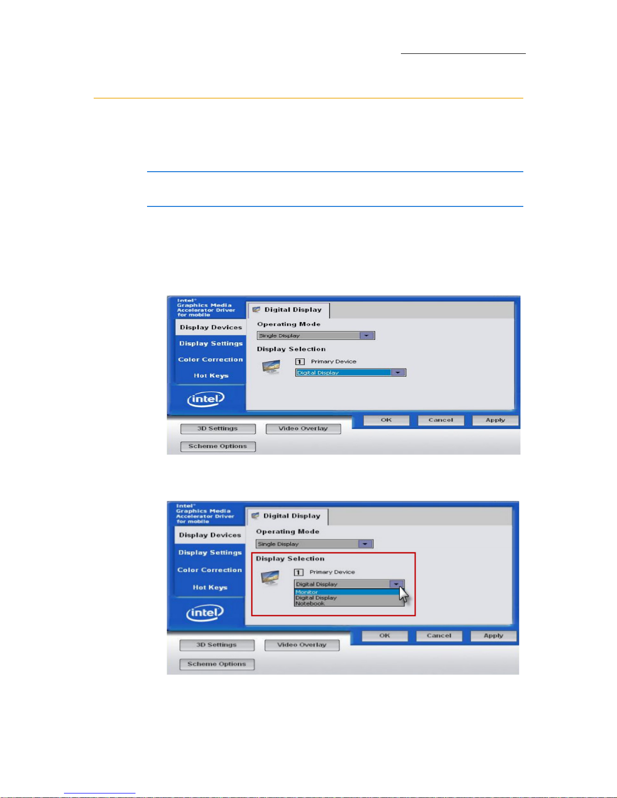
The Digital Display screen will open:
2. Under the
Display Selection click on the drop down menu for Primary
Device
and select Digital Display. (DVI Monitor)
Continued on next page...
Page 12
6
Compulite
Chapter 1
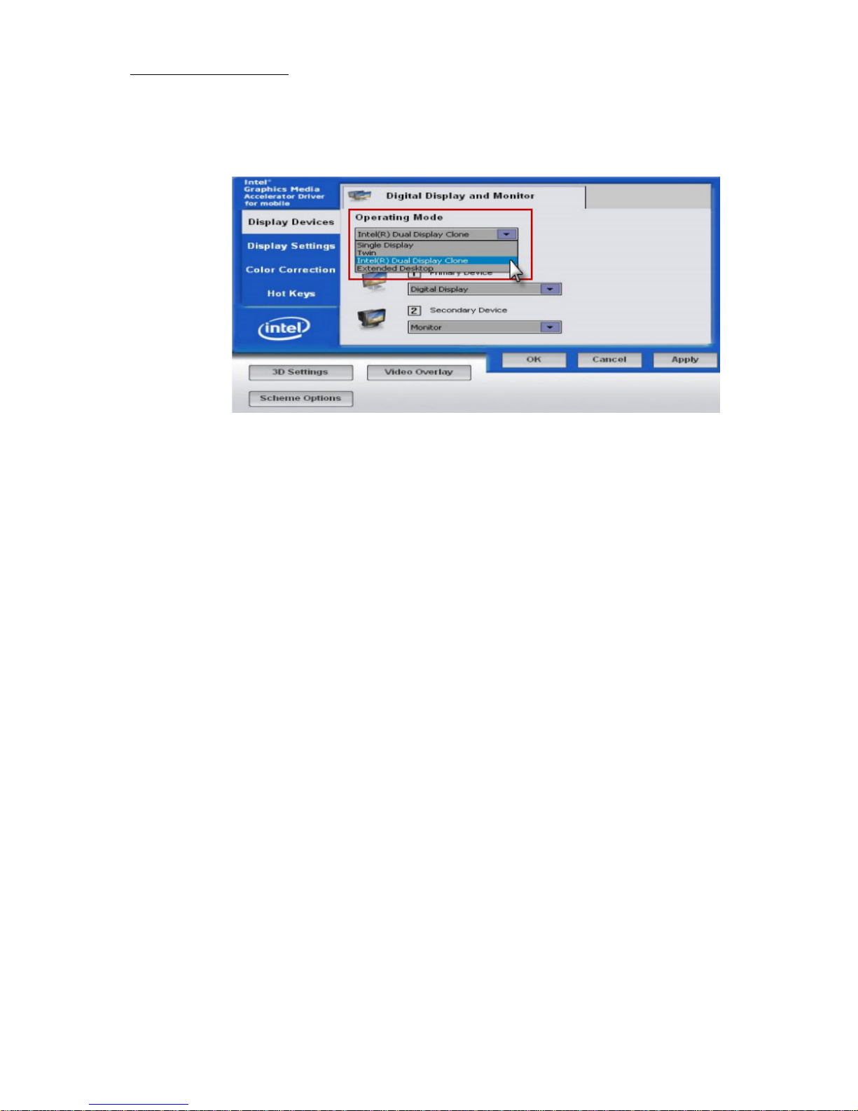
3. Click on the drop down menu under Operating Mode and select Extended
Desktop
. This will activate all the screens.
4. Click
Apply to apply the monitor settings.
5. Reboot System.
Page 13

7
VECTOR
SETTING UP AND OVERVIEW
Vector operation modes and programming syntax
Vector has two operation modes:
Trac k ing m od e
Compulite mode
Vector offers two syntaxes for programming procedures.
Action syntax
Enter syntax
The operation mode and programming syntax are set in the
System
Settings dialog boxEditing tab.
Tracking mode operation
In tracking mode, Vector stores only the changes or moves from one
cue to the next. Parameter levels that do not change are tracked
through cues following the cue where the level was originally set. Levels
that are being tracked are not stored again in each cue. Thus there are
two types of parameter values:
Hard values (new or changed values) - values that are stored in the
current cue.
Tracked values - unchanged values that are tracked from an earlier
cue.
After storing a cue, the editor is released.
Sometimes you want to cancel all tracking values, for instance, when
starting a new scene. Block cues are used to reset the tracking,Vector
automatically maintains the cue state when playing back cues out of
sequence, as often happens during rehearsals.
Compulite mode operation
Compulite mode is a cue only mode, where all fixtures and values that
comprise the lighting state are stored in each cue.
The editor is not released after storing a cue. You can continue
programming cues based on the editor group or reset the editor.
See:“
Resetting the editor” on page 51.
Page 14
8
Compulite
Chapter 1
Programming syntax
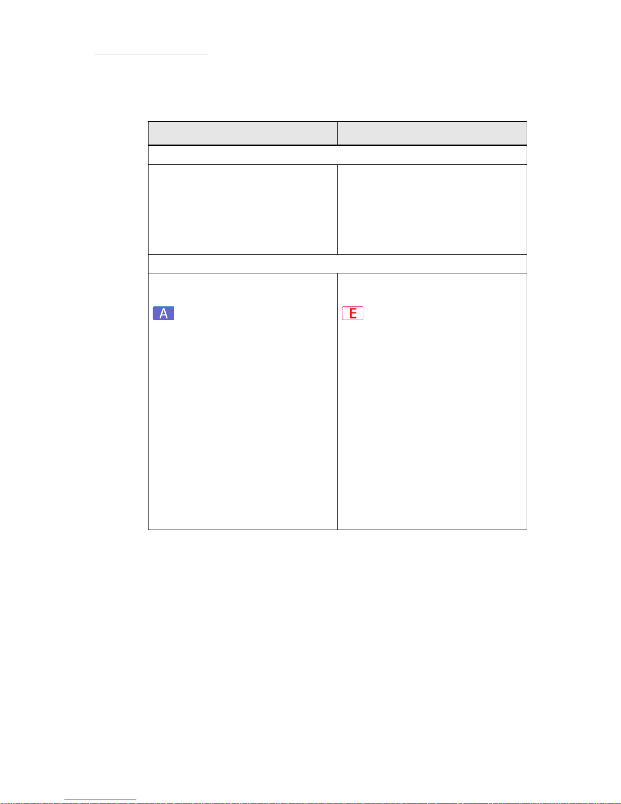
Action syntax Enter syntax
Output convention
• Parameter levels that are set using
@, are immediately output.
• Parameter levels set using the
wheels, FULL, ZERO, or ON are
immediately output.
• Parameter levels that are set using
@, are not output until ENTER is
pressed.
• Parameter levels set using the
wheels, FULL, ZERO, or ON are
immediately output.
Procedure syntax
Generally, action procedure syntax is:
1. Select items (fixtures, etc).
2. Select the object.
3. Select the operation.
Example: Store a group.
1. Select fixtures (the items).
2. Press GROUP and choose a group
number (the object).
3. Press STORE (the operation). The
group is stored.
Generally, enter procedure syntax is:
1. Select the items (fixtures, etc.).
2. Select the operation.
3. Select the object.
4. Press ENTER.
Example: Store a group.
1. Select fixtures (the items).
2. Press STORE (the operation).
3. Press GROUP and choose a group
number (the object).
4. Press ENTER.
Page 15
9
VECTOR
SETTING UP AND OVERVIEW
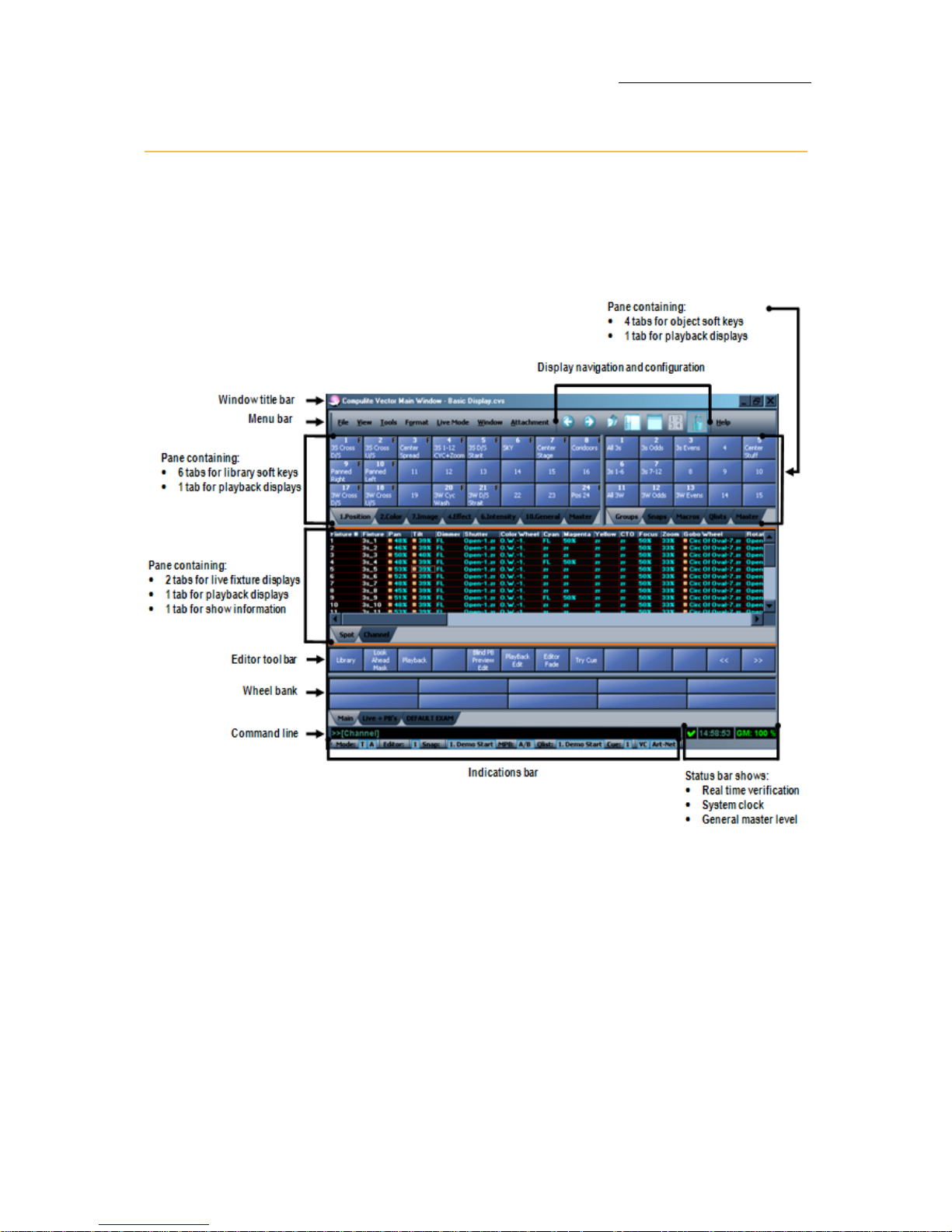
Basic display layouts
On start up, the touch screens open with basic display layouts. The
layouts are completely customizable and you can change the layouts to
suit your show and work habits. We recommend that you familiarize
yourself with the supplied layouts before changing them.
Figure 1: Typical basic layout
Page 16
10
Compulite
Chapter 1
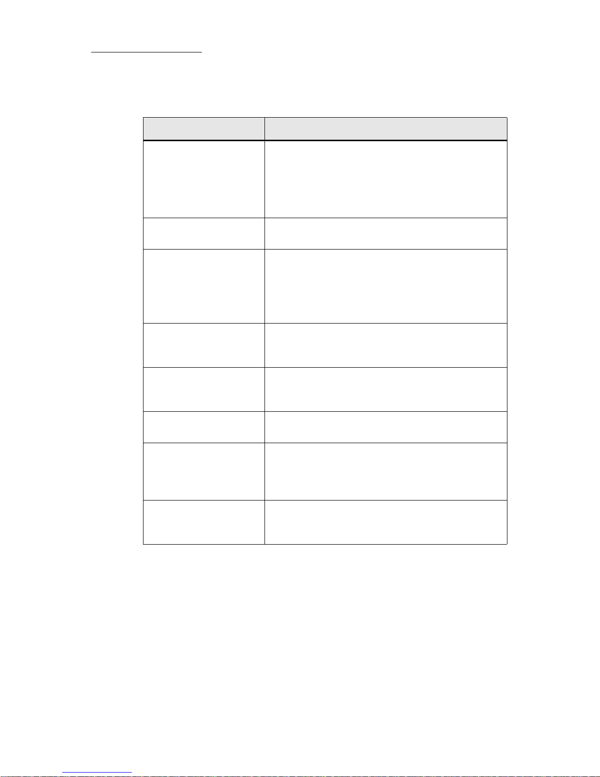
Screen elements
Screen element What does it show?
Window title bar • The show file name is displayed on the right.
• Minimize, maximize, and close window controls
are displayed on the left.
The title bar can be hidden to maximize display
real estate.
Menu bar Seven menus are available on the menu bar. Tap a
menu to view the options offered.
Display navigation • Standard display controls: go to previous view,
go to last view, go up on level.
• Vector icons to: open the Workspace tree, show/
hide the Window title bar, toggle soft key display
formats, and lock the display.
Tabs for soft keys Tabs, which are added to panes, display soft keys
for show objects and playback components. The
object category is set using the Workspace tree.
Tabs for displays Current status of output on the playback wings
(faders and QKeys), AB crossfader, and the master
playback.
Editor tool bar Vector’s system tool bar is context sensitive,
changing according to the current function.
Wheel Assignments The wheel display is context sensitive showing the
parameters for the selected moving device.
Wheels are also used for programming effects and
fade rate control.
Live displays A grid format shows the current output for
fixtures. The live display grid setup can be
modified in the Grid Properties dialog box.
Page 17
11
VECTOR
SETTING UP AND OVERVIEW
Note: It is recommended to lock the displays to avoid inadvertently
moving display elements. Press on the windows tool bar or choose
Lock Display under the Windows menu.
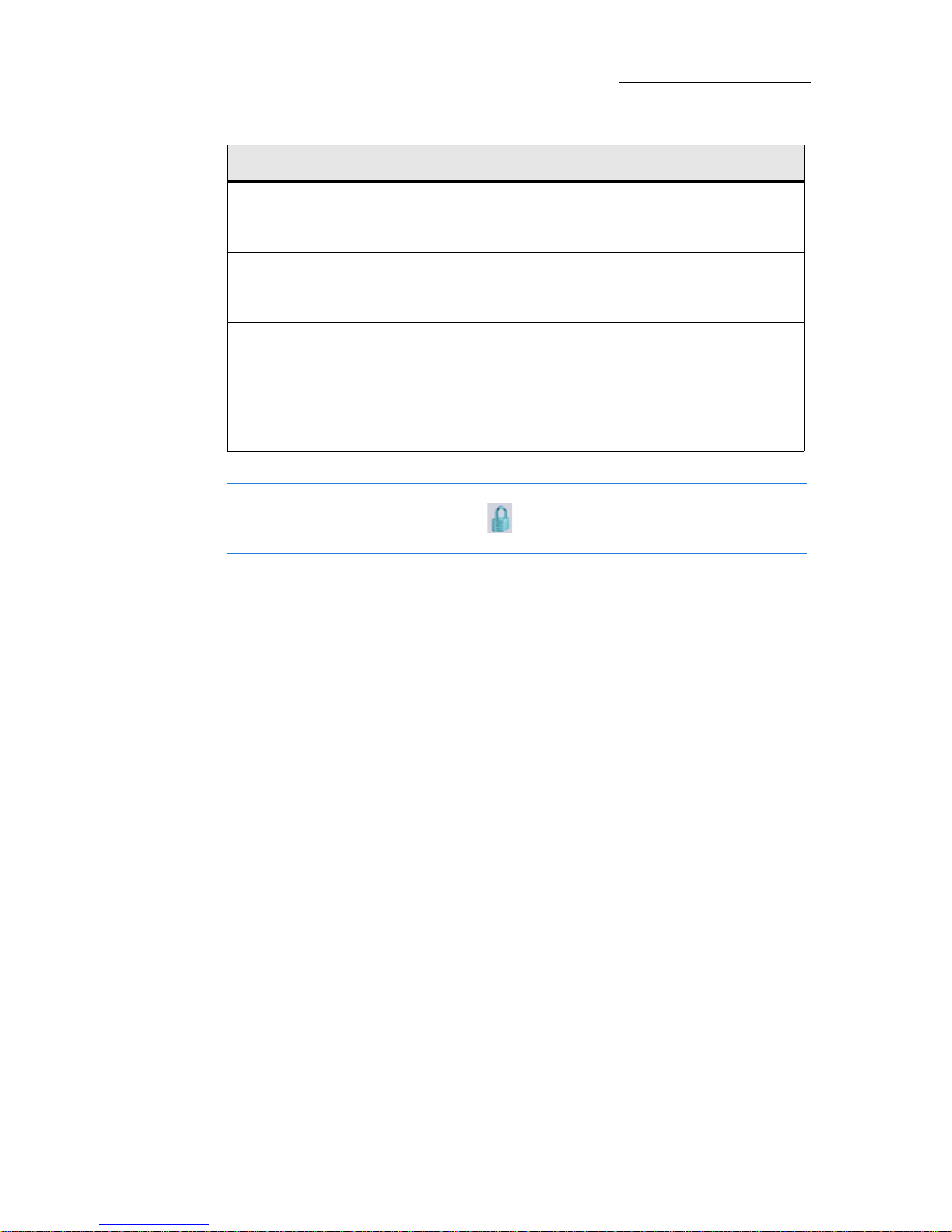
Command line The command line is the area where commands,
entered using the console keys or touch buttons,
are displayed. Each screen has a command line.
Indications bar The Indications bar shows system status
information. You can choose to show or hide the
Indications bar.
Status bar The status bar appears on the main screen only.
The status bar shows:
• Real time connection verification
•System clock
• General master status
Screen element What does it show?
Page 18
12
Compulite
Chapter 1
Pointing and navigating
Vector's user interface will be familiar to computer users (and that is
just about everyone).
Menus, toolbars, file trees, and dialog boxes make it easy to find your
way around and get things done.
Your pointing device can be an external mouse, connected at the mouse
port on the back panel, or the trackball set to mouse function.
Using the trackball
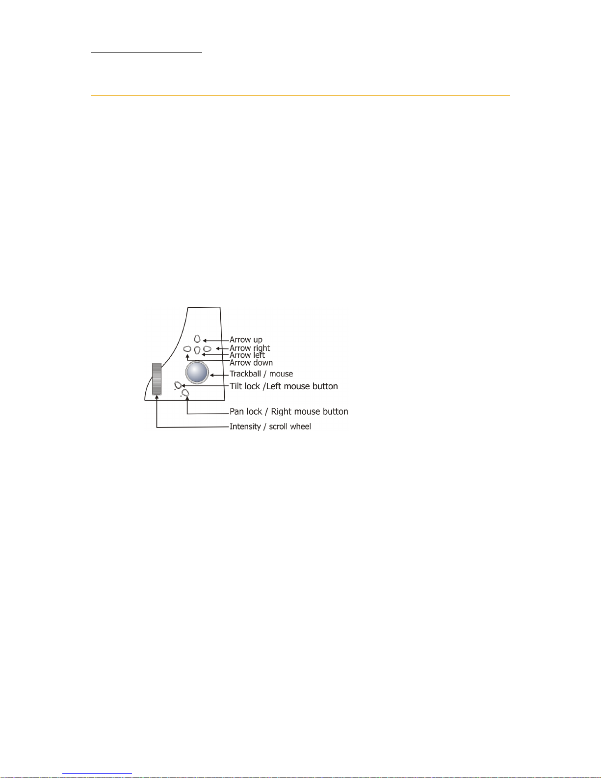
Vector's dual mode trackball is used for setting pan/tilt values and as a
mouse. The keys located at the lower left of the trackball function as
right and left mouse buttons when the trackball is set to mouse.
Figure 2: Console panel detail - Vector Red and Vector Blue
To set the trackball for mousing
Press MOUSE. The MOUSE LED flashes. The trackball now serves as a
pointer device.
Scrolling and navigating displays
The vertical wheel can be used as a scroll wheel in grid displays. When
the vertical wheel is set to windows, console keys can be used to enter
numbers in dialog box fields requiring numeric entries and to navigate
between fields in dialog boxes. The key cluster above the trackball are
used as arrow keys to traverse grid and fields.
To set the wheel for scrolling
Press SCROLL WIN. The SCROLL WIN LED flashes.
The message Windows Mode Active!!! overlays the command line.
Page 19
13
VECTOR
SETTING UP AND OVERVIEW
Using console keys in window mode
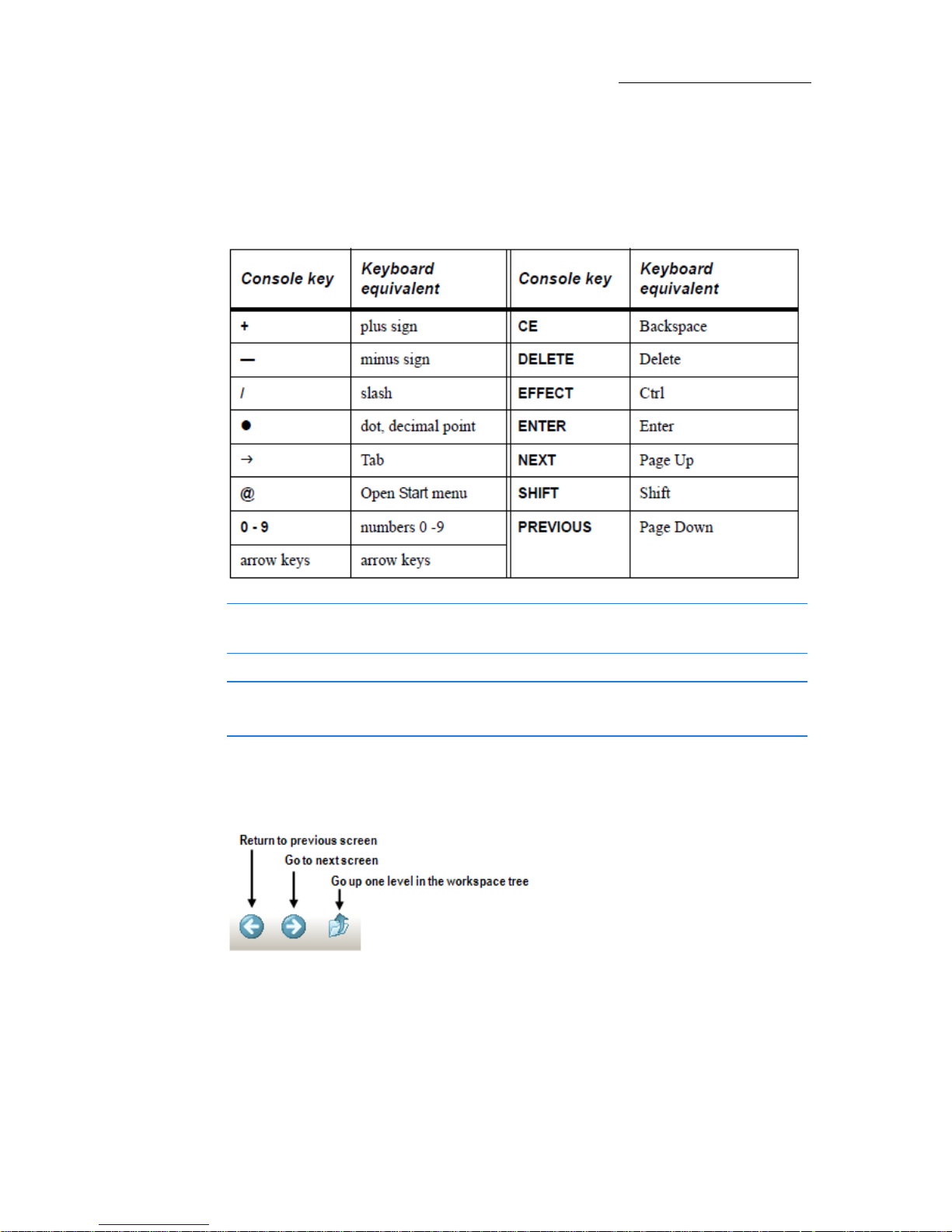
When the SCROLL WIN key is active, the console number pad and other
console keys can be used to enter numbers and traverse dialog box
fields. Console keys that are active in scroll win mode are:
Note: SCROLL WIN is automatically enabled when working in dialog
boxes. SCROLL WIN is automatically released when exiting a dialog box.
IMPORTANT! When SCROLL WIN is enabled, the numeric keypad is
disabled for fixture editing and the wheel does not control intensity.
Pane navigation tools are displayed at the end of the menu bar. You can
show or hide these icons through the
Customize dialog box found under
the
To ol s menu.
Figure 3: Basic pane navigation
Page 20
14
Compulite
Chapter 1
Setting up displays
Each screen has one general window that includes:
Menu bar
The command line and status bar.
A title bar with window control icons. The title bar does not appear
in the default windows. To show or hide the title bar: Open the
Window menu and choose Show/Hide Window Title.
Opening new windows
New windows always open, in reduced size, on the main screen. You
then move them, using a mouse or stylus, to an empty display screen.
To open and place a window:
1. Go to the Window menu and tap New Window.
A new window opens on the main display screen.
2. Using the mouse, a stylus, or the trackball set to the mouse option,
drag the new window to one of the display screens.
3. When the window is located on the display screen, maximize it.
4. Optional: hide the window title bar:
Window>Show/hide window Title.
Opening new view panes
The splitter mechanism is used to segment the display area and create
new view panes.
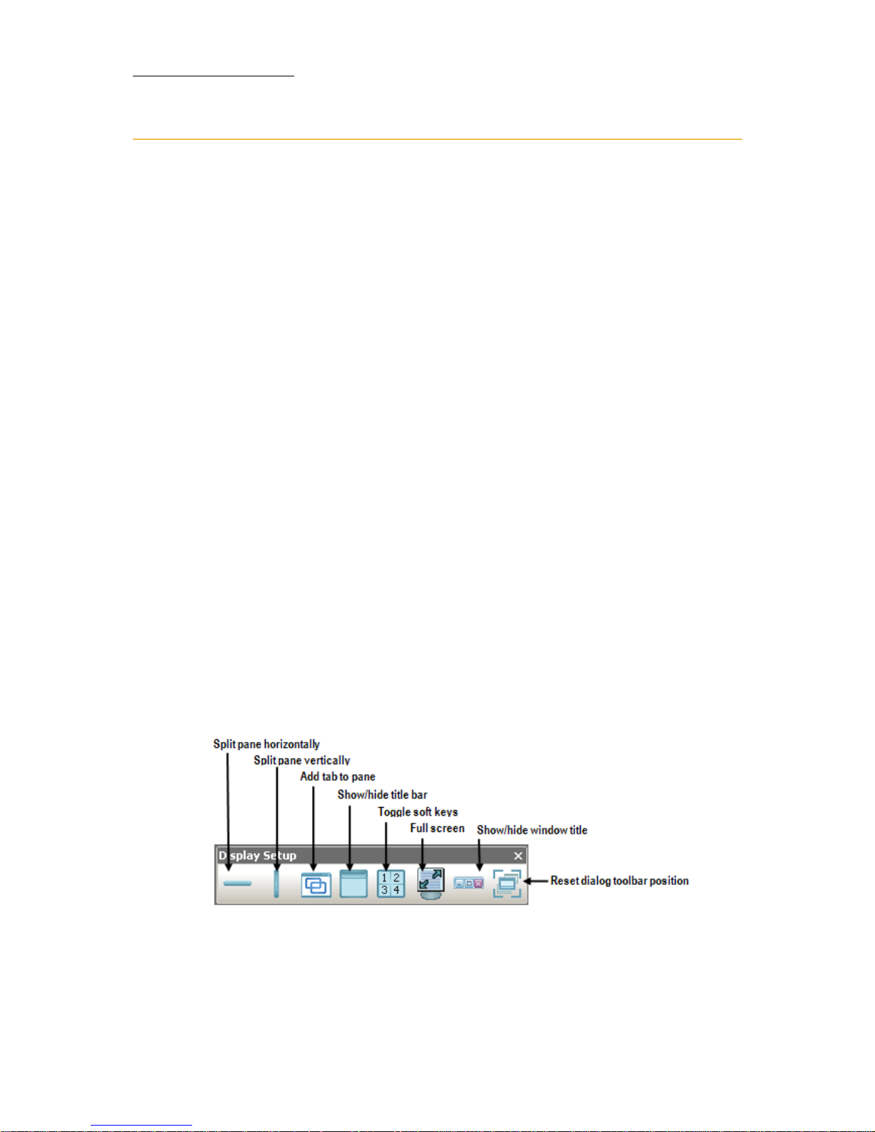
Figure 4: Display Setup toolbar
Page 21

15
VECTOR
SETTING UP AND OVERVIEW
There are three options for segmenting the display area:
Split horizontally - Split the active pane horizontally.
Split vertically - Split the active pane vertically.
Add a tab to an existing pane - Open a new tab in the active pane.
The tab’s content is set using the Workspace tree.
To access display setup tools
The display setup tools are available under the Window menu.
Or
Tap
Display Setup Tool bar to open a floating tool bar on the display.
Page 22
16
Compulite
Chapter 1
Setting Up Soft Keys
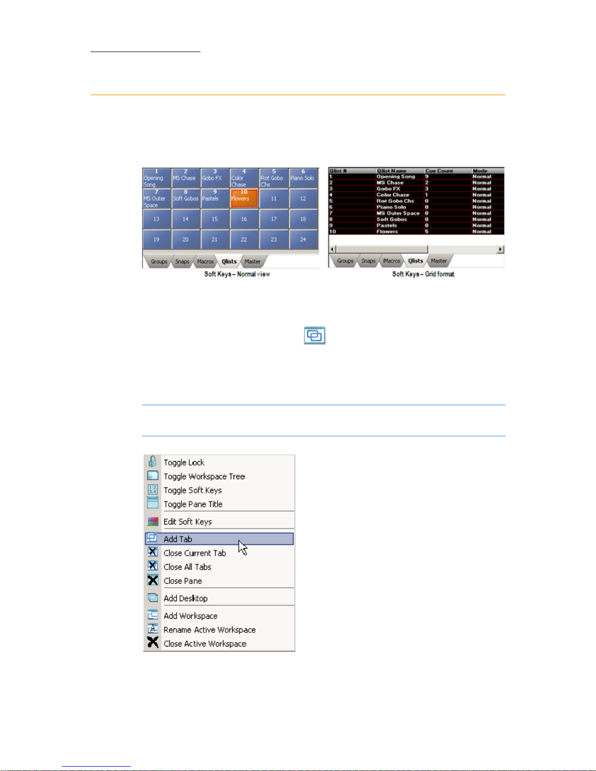
Tabs added to panes serve as soft keys. Each pane can host many tabs.
Soft keys can be displayed as numbered buttons or in grid format:
To open a new tab
Go to the Window menu and tap . A new tab opens in the active
pane.
OR
Right click anywhere on the display to open the shortcut display menu.
Note: Not all display set up options are available in the shortcut
display menu.
Figure 5: Right click display menu options
Page 23

17
VECTOR
SETTING UP AND OVERVIEW
Defining soft keys
Tabs can be defined as soft keys for libraries, QLists, groups, snaps, or
macros.
To define a tab
Set a tab for position libraries.
1. Tap the tab to make sure it is the active tab.
2. Open the Workspace.
3. Expand the Library node.
4. Ta p
POSITION.
5. Go to the next tab and repeat step 3 until all of the soft key tabs are
set.
To toggle the soft key display
Tap , located on the menu bar or in the Window menu.
Paging soft keys
The number of soft keys displayed depends on the size of the pane.
To page soft keys
Press SCROLL/WIN and page using NEXT and PREVIOUS.
OR
Use PageUp and PageDown on the keyboard.
OR
Use the arrow keys on the pane’s title bar. Tap to show/hide the
pane title bar.
OR
You can hover the mouse over the SK view and use the mouse wheel to
scroll through the pages.
Page 24
18
Compulite
Chapter 1
Workspaces
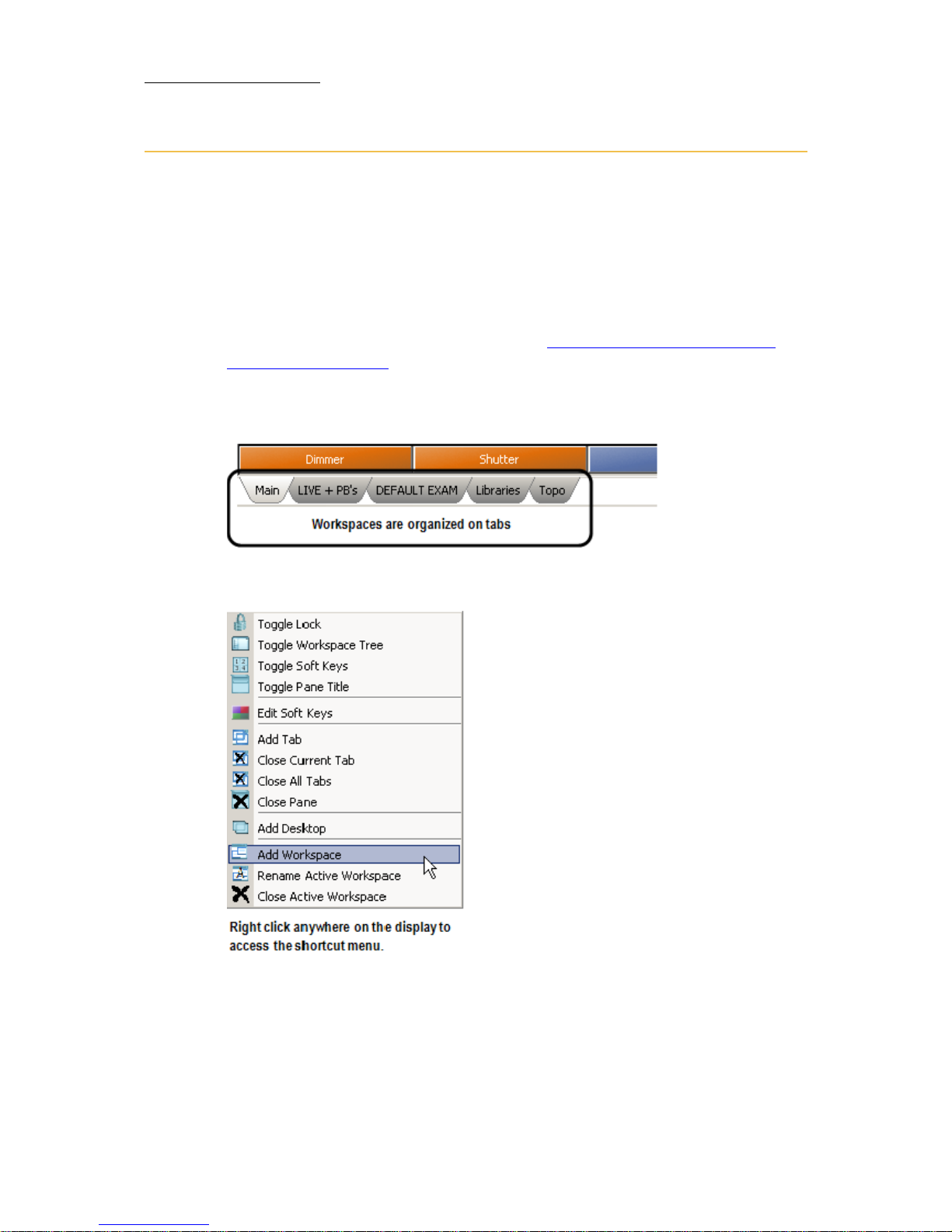
Each main window can contain more than one workspace and you can
have up to 7 workspaces per window. Workspaces are accessed by tabs
located above the command line, so switching is very simple. You can
create a dedicated workspace for playback information, live displays,
etc.
Workspaces are saved as part of the layout or they can be saved
separately and loaded for re-use. (See:“
Saving and loading display
layouts” on page 24).
The default workspace is called
Main and it is the first workspace tab.
Workspace tabs can be renamed and their order can be changed.
Figure 6: Workspace tabs
Figure 7: Display controls - right click menu
Page 25

19
VECTOR
SETTING UP AND OVERVIEW
To add and configure workspaces
1. In the window, right click anywhere and choose Add View on the right
click menu.
Or
Go to the
Window menu Window Options and choose Add Workspace.
A workspace is added to the window. Its tab appears to the right of
the last tab.
2. Right click the new tab.
The display control, right click menu opens.
3. Choose
Rename View.
4. Type a new name for the workspace and press
ENTER.
5. Through the
Window menu divide the workspace into panes and add
tabs, as necessary.
6. Open the
Workspace tree .set up the view. (See:“Using the
Workspace tree” on page 20).
Example: If you have created a Live workspace, you will probably
want to show the live fixture displays, the master playback display,
and the playback wing display.
7. Optional - Save this as a display layout (See:“To
save a workspace”
on page 25).
Page 26
20
Compulite
Chapter 1
Using the Workspace tree
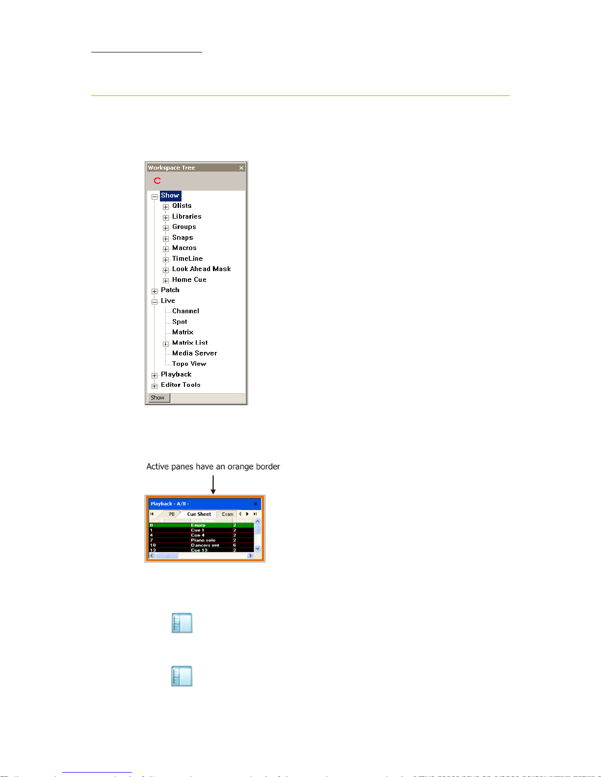
The Workspace tree is a navigable tree used to populate the workspaces
you have set up on the display.
Figure 8: The Workspace tree
Tapping an item in the Workspace tree displays the selected item in the
active pane.
Figure 9: Active pane
To open the workspace tree
Click , located on the tool bar.
To close the workspace tree
Click .
Page 27
21
VECTOR
SETTING UP AND OVERVIEW
To expand a node
Click the plus sign (+).
To collapse a node
Click the minus sign (-).
To collapse the entire tree
Click
To display the Workspace tree
Tap on the menu bar.
A floating
Workspace opens.
Show node
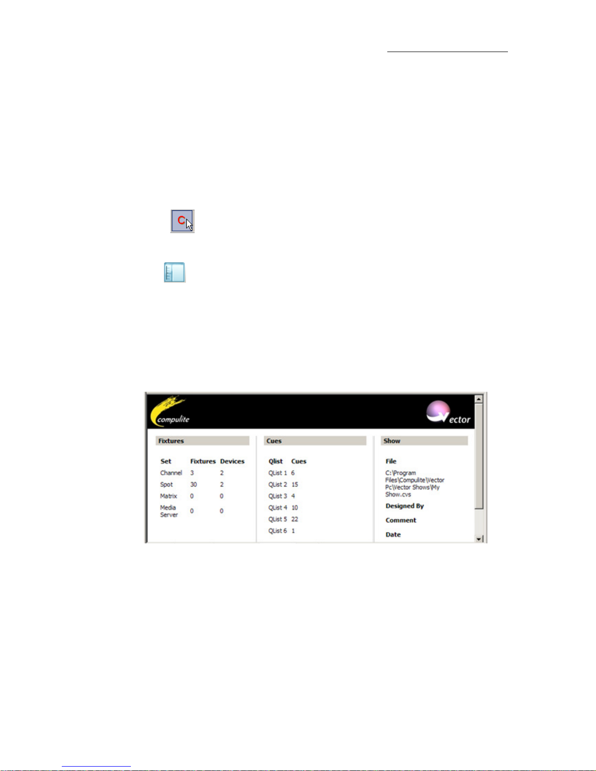
New panes always default to the Show display, which can also be
selected from the
Workspace tree. This display contains general show
information.
Figure 10: Show information
Tap a child node to view or set a tab for:
• QLists • Snaps • LookAhead Mask
•Libraries •Macros •Home Cue
• Groups • TimeLine
Page 28
22
Compulite
Chapter 1
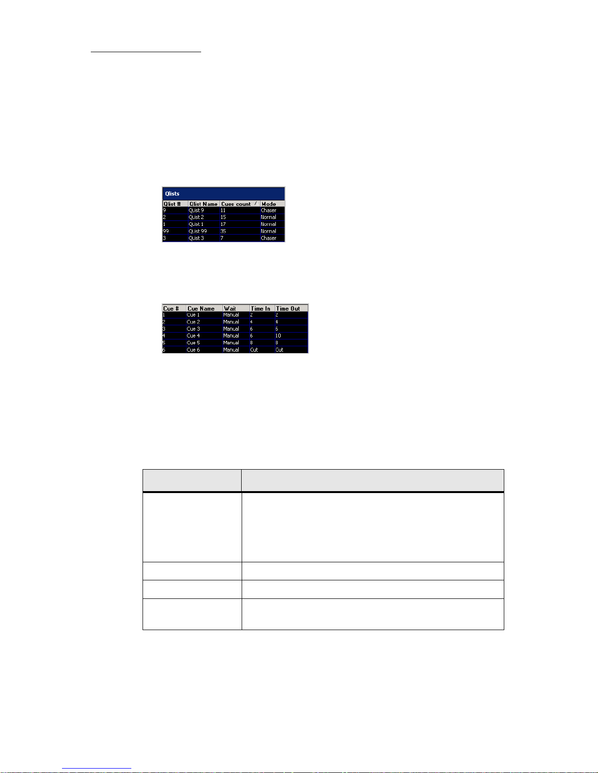
To view cue sheets
Example: View QList1 and examine cue 1.
1. Expand
Show.
2. Ta p
QLists.
A list of QLists is displayed in the active pane.
3. Expand
QLists and tap QList 1.
A list of cues in QList 1 and cue information is displayed in the active
tab.
4. Ta p
Cue 1. The fixtures in cue 1 are displayed with their parameter
values.
5. Expand
Cue 1 and tap a fixture set.
The details of the selected fixture set are displayed.
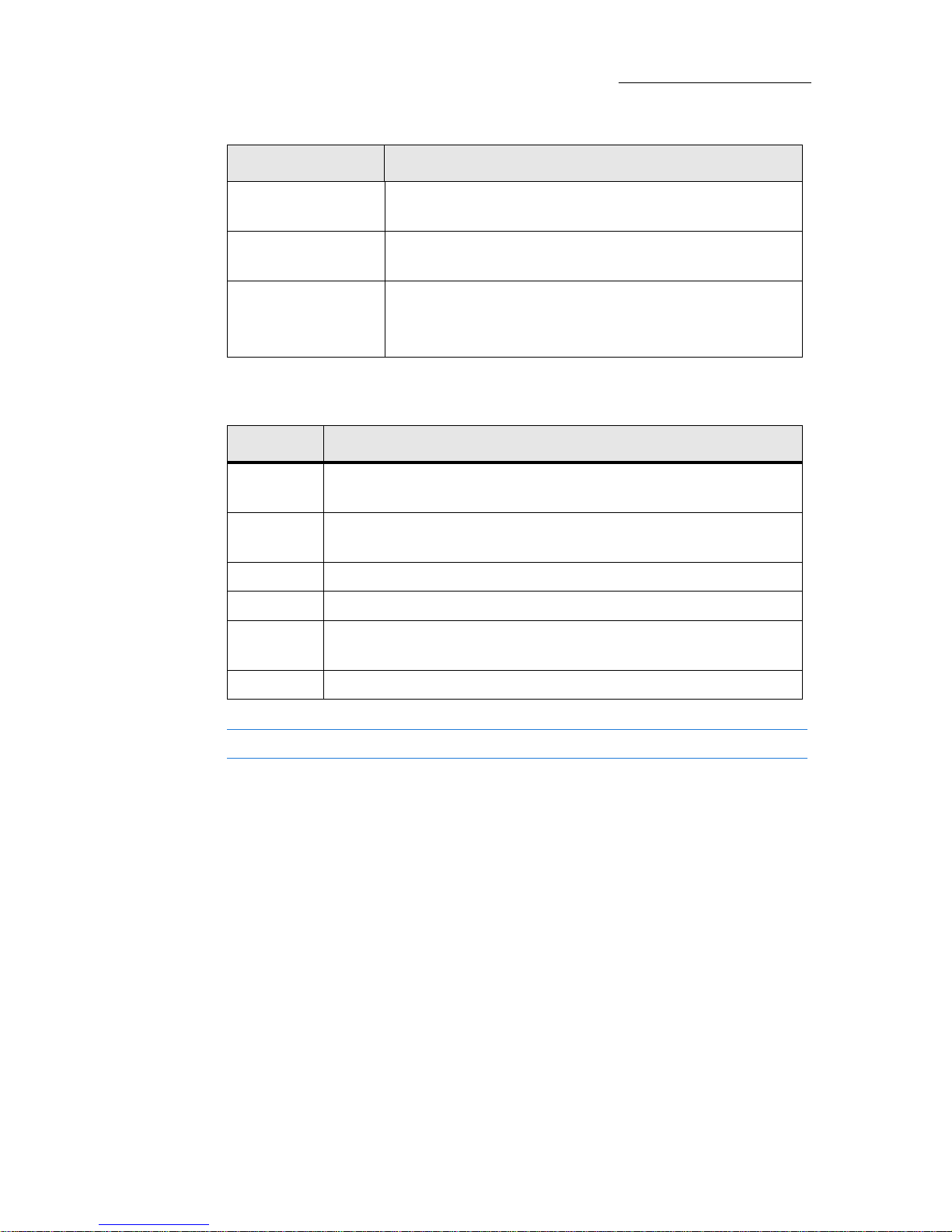
Editor Tools node
Node Function
Context Sensitive The contents of a Context Sensitive tab or pane change
according to the current selection type. These soft keys
can then be used for selections. Example: Press
CHANNEL. The CS soft keys are set to channel. Tap soft
keys to select channels.
Wheel Assignments Show/hide the Wheel Assignments display.
Editor Toolbar Show/hide the Editor Toolbar
Attachment Viewer Attach and delete attachments to show objects. Add
text notes to an attachment.
Page 29
23
VECTOR
SETTING UP AND OVERVIEW
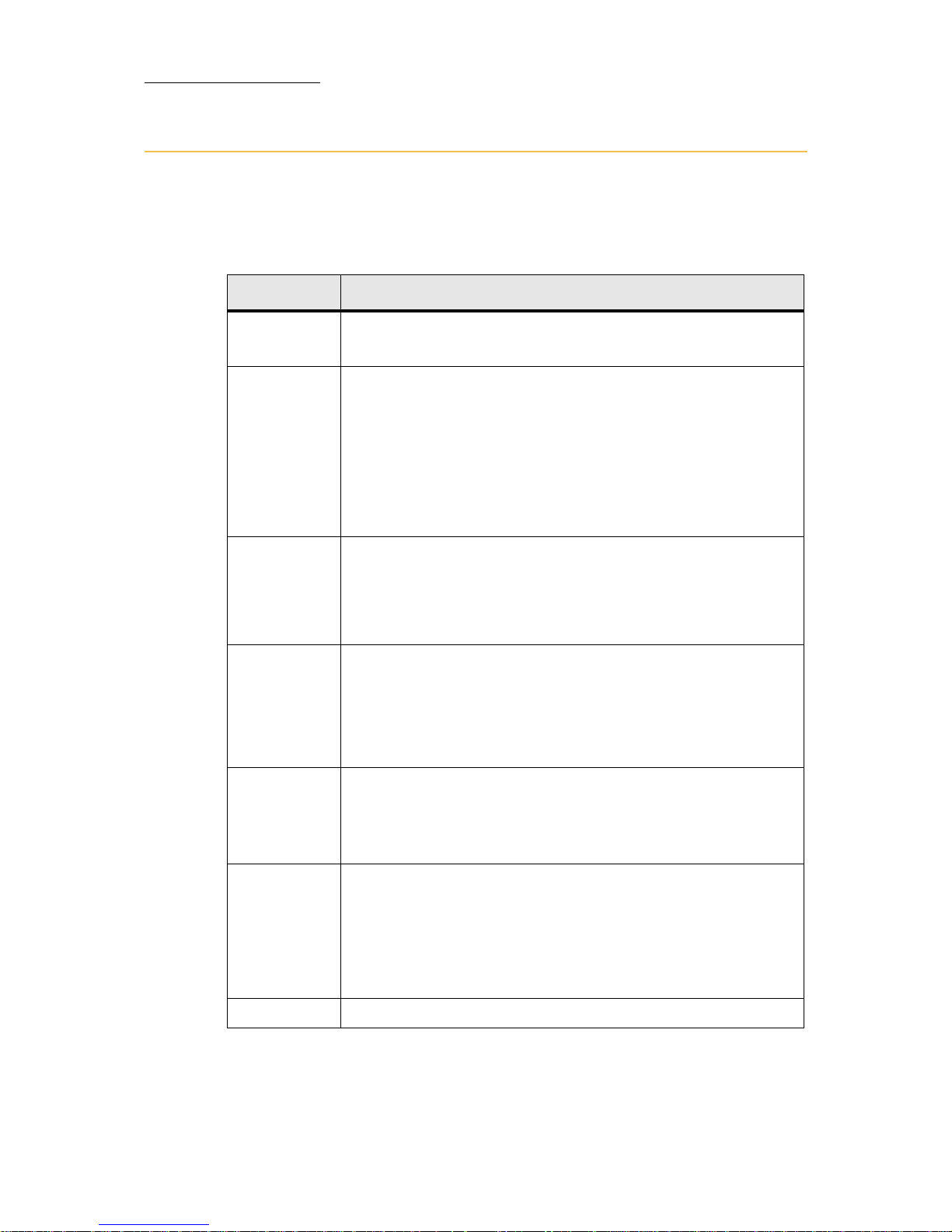
Live node
Tip! Use a large display pane for live fixtures.
Camera Viewer View images seen by the camera connected to Vector
on the USB port or via IP address.
Scheduler The scheduler is a tool for setting events that trigger
macros according to date and time settings.
Desktop list Desktop is a special display area that functions just like
the desktop on your pc. Populate it with
icons for one click or hot key operation.
Node Function
Node Function
Channel Displays, in the active pane, the channels in the show and their
current output.
Spot Displays, in the active pane, the spot in the show and their
current output.
Matrix Displays the matrix programmer.
Matrix List Displays a list of all matrixes defined in the Patch Manager.
Media
Server
Displays the media servers in the show and their current
output.
Topo View Displays the topo map defined in the Patch Manager.
Page 30

24
Compulite
Chapter 1
Saving and loading display layouts
Display layouts are saved in dedicated files and also in the show files.
The extension for layout files is *.cfg
There are three default folders that contain display layouts:
D:\Program Files\Compulite Vector\WorkDir\Show\Layout - This is the default
location for saving layouts for the current show. When saving a
show, the screen layout is automatically saved with same file name
as the show. The contents of this folder are overwritten when
starting a new show.
D:\Program Files\Compulite Vector\Config\Layout - The layouts stored here
are system layouts. These are the basic layouts included in the
Vector software. If you customize and store your own system
layouts, give them a unique name so they are not overwritten when
upgrading software.
D:\Program Files\Compulite Vector\My Layouts - The contents of this folder
are never overwritten. Display layouts that you want to save and
resume copy to this folder.
Tip! You can at anytime load the system default layout if you so wish.
(Window Layout Load System Layout Load “Default Layout”)
To save a display layout
1. Ta p Window Layout Save System Layout OR Save Show Layout.
The
Save As dialog box opens to the default folder.
2. Optional - browse to a different folder.
3. Type a name in the
File Name field.
4. Ta p
SAVE.
The display layout is saved.
To load a display layout
1. Ta p Window Layout choose Load System Layout or Load Show Layout.
The
Open dialog box opens.
2. Select a layout from the list of *.cfg files.
3. Ta p
OPEN.
The layout is loaded.
Page 31

25
VECTOR
SETTING UP AND OVERVIEW
Tip! Back up your saved layouts by copying the files to a different loca-
tion on the hard disk.
To save a workspace
The workspace file extension is: csl.
1. Go to the
Window menu Layout choose Save Workspace.
The
Save As dialog box opens to the default folder.
2. Optional - browse to a different folder.
3. Type a name in the
File Name field.
4. Ta p
SAVE.
The workspace is saved.
To load a workspace
1. Ta p Window Layout choose Load Workspace.
The
Open dialog box opens.
2. Select a workspace from the list of *.csl files.
3. Ta p
OPEN.
The workspace is loaded.
ATTENTION! If for some reason you cannot see your dialogs or
toolbars, then you can reset them using
Window Reset Dialog Position. This
will bring all toolbars and dialogs to there default screen positions.
Page 32
26
Compulite
Chapter 1
Menus and toolbars
Vector’s menus are displayed in the menu bar at the top of the window.
Tool bars are available in each menu or you can open floating tool bars.
Floating tool bars can be docked under the menu bar.
Menu Features and toolbars
File • Save and open show files
•Print shows
View • Manipulate how grid formats fit into the display space.
This affects how many channels and spot parameters are
visible.
• Set live views to jump according to fixture selection (spots
and channels) and parameter selection (spots).
• Open the Grid Properties dialog box.
•Show/hide the View toolbar.
To ol s • Open the Patch Manager.
• Open the System Settings dialog box.
• View real-time status.
• Customize the default display.
Format • Set parameter value formats (percent, decimal, or hexa-
decimal) in the live spot and channel displays.
• Display time, library, effect, or profile details in parameter
cells.
•Show/hide the Format toolbar.
LiveMode • Determine which fixtures are displayed in the live channel
and spot displays; All fixtures, fixtures active on stage,
active in the editor, etc.
•Show/hide the LiveMode toolbar.
Window • Arrange panes and add tabs on the general window
• Toggle soft key views
•Lock displays
•Show/hide the Display Setup toolbar.
• Save and load display layouts
Attachment • Work with file attachments
Page 33

27
Chapter 2 Starting a New Show and
Patching
In this chapter you learn about the Patch Manager and how to:
Open a new show file
Import devices
Create and patch fixtures
Delete fixtures and clear addresses
Apply the patch to your show
Patch fixtures to addresses using the DIM key on the console
Page 34

28
Compulite
Chapter 2
Opening a new show file
Opening a new show file, clears all current data including the patch,
show settings, and cues.
To open a new show
1. Go to the File menu.
2. Choose
New Show.
You are prompted to save the current show.
3. Click
YES or NO.
If yes, the current show is saved.
If no, all current data is lost.
In both cases, all current show data (including the patch) are
cleared from the system.
Page 35

29
VECTOR
STARTING A NEW SHOW AND PATCHING
The Patch Manager
At start up, Vector's patch is empty. The system must be set up for the
number and types of fixtures that will be used in the show. Opening a
new show file resets the patch to empty and clears all current data.
Determining the type and number of fixtures used in the show and
patching these fixtures is done in the
Patch Manager.
The
Patch Manager’s features include all patch and configuration
activities:
Determining the type of fixtures used in the show.
The number of fixtures.
Assigning fixture numbers used when programming.
The pan and tilt orientation for moving devices.
Patching fixtures to DMX addresses.
Fixtures are organized into Sets, which are groups of generic fixture
types:
Set 0 - Channel
Set 1 - Spot
Set 2 - Matrix
Set 3- Media server
The patch display is in grid format. Each set has its own grid.
During patching, Vector automatically calculates the DMX length for the
fixtures.
When the
Patch Manager is open, you can still perform any show
programming functions.
To open the Patch Manager
Tap To o ls menuPatch Manager.
Importing devices
You must import the devices that you intend to use in your show.
Devices are imported from a list of device files. The
IMPORT DEVICE button
in the
dialog boxes opens the list of device files.
Page 36
30
Compulite
Chapter 2
To import a device
1. Ta p .
A dialog box containing a list of device files opens.
2. Double click the device file.
Or
Tap the device file and tap
OPEN.
The device is imported to Vector's
Patch Manager. It appears under the
Device folder in the workspace tree.
3. Repeat this procedure to add more devices to the
Patch Manager’s
Device folder.
Note: To select more than one device, hold down Cntrl and click more
devices. When your selection is complete, click
OPEN. The selected
devices are imported.
Creating and Patching Fixtures
Patching fixtures is a two-step procedure:
1. Creating fixtures
2. Patching fixtures to DMX addresses
There are separate dialog boxes for creating fixtures and patching
fixtures. There is also a wizard for both creating and addressing
fixtures.
Icon Opens dialog box
Create Fixtures - configure the number of fixtures for each device.
Patch Fixtures to DMX addresses.
Create and Patch Fixtures:
• Configure the number of fixtures for each device.
• Patch fixtures to DMX addresses.
Page 37

31
VECTOR
STARTING A NEW SHOW AND PATCHING
To create and patch fixtures
1. Expand Sets node in the Patch Manager workspace and choose a device
type.
2. Click .
The
Create and Patch wizard opens.
3. Select a device from the device drop down list.
Note: If the device does not appear in the list, you can import it now
by tapping
IMPORT DEVICE and following the steps for Importing devices
(see page 29)
4. Enter the desired number of fixtures in the Create Number of Fixtures
field.
5. Assign a start number in the
Start Number field.
The start number refers to the fixture number.
Example: To create 24 Mac 500 fixtures that will be numbered from
1 - 24, enter 1 as the start number.
6. Optional: Change the fixtures’ default name by typing a new name
in the
Name field. This name appears in the Live display.
7. Optional for moving devices: Change pan and tilt orientation.
8. Ta p
NEXT.
The patch address section is now displayed.
9. Enter the DMX universe number in the
Port field.
10.Enter the DMX start address in the
DMX address field.
11.Optional: In the
Patch interval field, enter the desired interval.
The default interval is the number of DMX channels used by the
device
12.Click
FINISH; the wizard closes.
The grid for the selected set is displayed.
Note: If nothing is specified for steps 10 - 12, Vector automatically
assigns the next available address.
Page 38
32
Compulite
Chapter 2
Creating and patching fixtures with scrollers
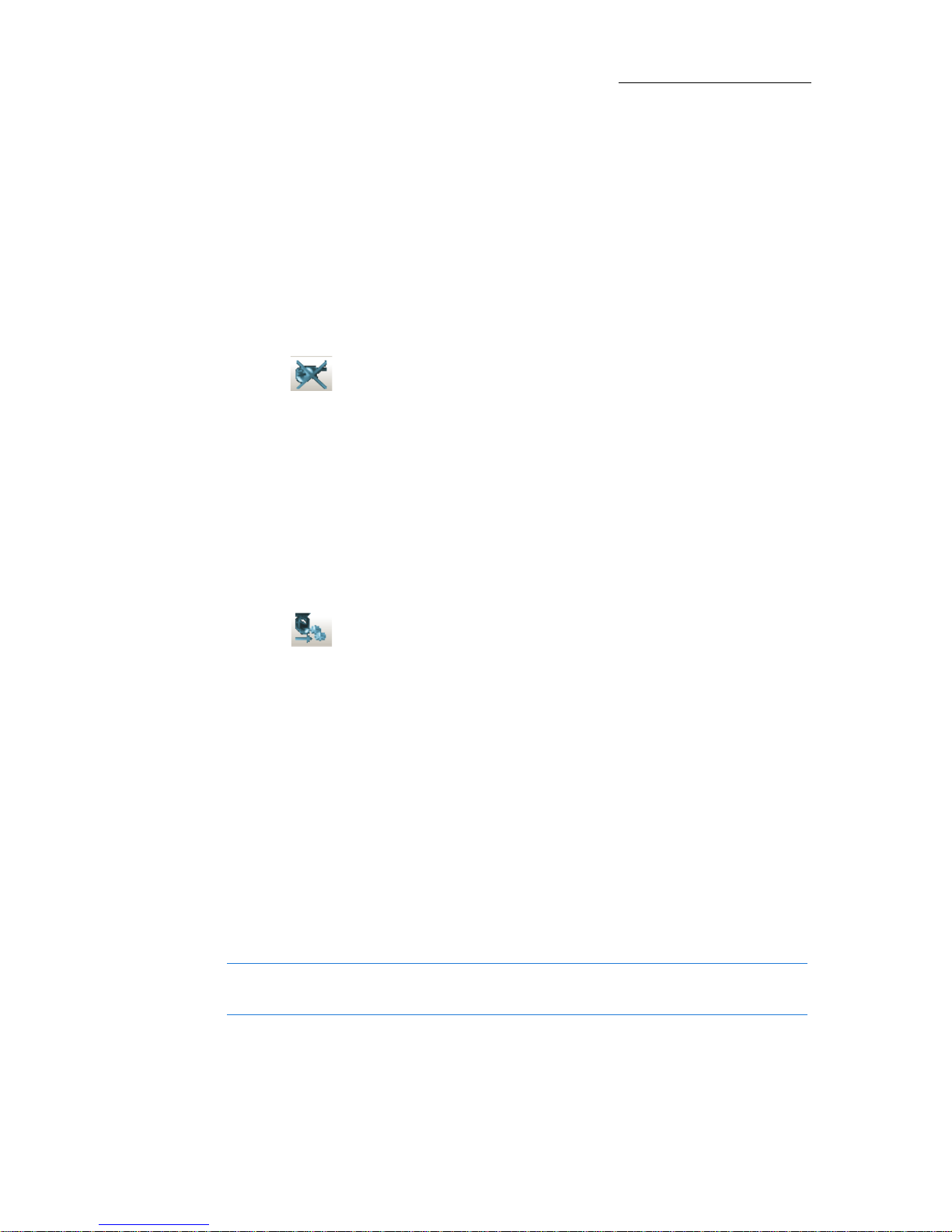
Fixtures with scrollers can belong to either the channel set or the spot
set.
Scrollers that are part of the channel set appear in the channel display.
The frame value is displayed in the color column. Scrollers that are part
of the spot set appear in the spot display.
The frame value is displayed in a color parameter column. In both
cases, it is necessary to select only the spot or channel number to
access the dimmer and the scroller.
Figure 11: Scrollers as channels and spots
IMPORTANT! Patch scrollers to external dimmer.
Deleting fixtures and clearing patch assignments
Fixtures and patch addresses can be deleted at any stage of the work.
IMPORTANT! Always clear patch assignments before reassigning DMX
addresses.
To delete fixtures
1. Select the appropriate Set (Channel, Spot, Media Server, or Matrix).
2. Ta p .
The
Delete Fixture dialog box opens.
Continued on next page...
Page 39
33
VECTOR
STARTING A NEW SHOW AND PATCHING
3. Enter the fixtures’ numbers in the From No. and To No . fields.
4. Ta p
OK to update and close the dialog box. The selected fixtures are
deleted from the patch and no longer appear in the grid.
Or
Tap
APPLY and keep the dialog box open.
To clear addresses
1. Select the appropriate Set.
2. Ta p . Th e
Clear Patch dialog box opens.
3. Enter the fixtures’ desk numbers in the
From No. and To No . fields.
4. Ta p
OK to update and close the dialog box. The patch for the
selected fixtures is cleared and no longer appears in the grid.
Or
Tap
APPLY and keep the dialog box open.
To adjust pan and tilt orientation in the patch manager
1. Select the spot set.
2. Ta p .
Or
Right click on the fixture cell and choose
Modify Range from the
shortcut menu.
The
Modify Fixtures wizard opens.
3. Enter the range of fixtures in the
Fixture no. field.
4. Ta p
NEXT.
5. Choose all or one of the following options:
INVERT PAN
INVERT TILT
SWAP PAN/TILT
6. Ta p FINISH.
Tip! You can also set the Pan/Tilt patch via the Editor toolbar outside
the Patch manager.
Page 40
34
Compulite
Chapter 2
Applying the patch and exiting the patch manager
Apply the patch when you want to save the patch, update the show,
and continue working in the
Patch Manager. Neglecting to apply the
changes in the patch while continuing to work in the
Patch Manager can
cause anomalies. For instance, you have cleared the patch for a number
of fixtures and now attempt to patch using the DMX addresses you just
cleared.
If you have not applied the patch after clearing, the system generates
the message: Patch Exists. Applying the patch after the clear operation
prevents this type of error.
To apply the patch
Click .
To exit the Patch Manager
1. Click . You are asked to save the patch data.
2. Click
YES to save changes. Click NO to exit without saving.
Note: If you chose YES, exiting the patch manager automatically
applies the patch.
Page 41

35
VECTOR
STARTING A NEW SHOW AND PATCHING
Patching using console keys
Pressing DIM on the console or PATCH on the Editor tool bar puts the tool bar
in patch mode.
The
Editor toolbar buttons are:
CLEAR PATCH
EXTERNAL PARAMETER (patch address for an external dimmer)
PARK
PROPORTIONAL LEVEL
CLEAR PROPORTIONAL LEVEL
FLASH
INPUT PATCH TO
DIMMER PROPERTIES
When patching in live mode it is useful to view the patch sheet. Open
the patch sheet through the
Workspace tree. See: “Using the Workspace
tree” on page 20.
To patch channels or spots
Example: Patch channel fixture 5 to DMX address port 2 dimmer 24.
1. Select channel 5.
2. Press
DIM.
3. Press
2 (the port) / (slash) 24 (dimmer) or use the direct dimmer
number, in this example, 536.
4. Press
STORE. The command line shows Assigned when the operation is
successful.
OR
1. Press
DIM.
2. Enter the dimmer number on the numeric keypad.
3. Press
CHANNEL and 5.
4. Press
STORE.
Page 42

36
Compulite
Chapter 2
To clear patching
Example: Clear the patch assignment for channel 5 which is patched to
port 1, DMX offset 5.
1. Select channel 5.
2. Press
DIM.
3. Press
DELETE. The Delete dialog box opens.
4. Press
DELETE again. or tap DELETE in the dialog box. The command
line shows
Released when the operation is successful.
OR
1. Press
DIM.
2. Select the dimmer by pressing
1/5.
3. Ta p
CLEAR PATCH (on the Editor toolbar). The Delete dialog box
opens.
4. Ta p
DELETE.
To patch external dimmers
Example: Channel 8, patched to DMX channel 8, is a fixture with a
scroller. Patch the external dimmer number, for the scroller, to DMX
channel 108.
1. Press
DIM and select the dimmer number, 108.
2. Ta p
EXTERNAL PARAMETER.
3. Select fixture channel 8.
4. Press
STORE.
To patch channels or spots
Example: Patch channel fixture 5 to DMX address port 2 dimmer 24.
1. Press
DIM or PATCH.
2. Enter the dimmer number on the numeric keypad.
3. Press
CHANNEL and 5.
4. Press
ENTER.
OR
1. Select channel 5.
Continued on next page...
Page 43

37
VECTOR
STARTING A NEW SHOW AND PATCHING
2. Press DIM.
3. Press
2 (the port) / (slash) 24 (dimmer) or use the direct dimmer
number, in this example, 536.
4. Press
ENTER. The command line shows Assigned when the operation is
successful.
To patch external dimmers
Example: Channel 8, patched to DMX channel 8, is a fixture with a
scroller. Patch the external dimmer number, for the scroller, to DMX
channel 108.
1. Press
DIM and select the dimmer number, 108.
2. Ta p
EXTERNAL PARAMETER.
3. Select fixture channel 8.
4. Press
ENTER.
Page 44

38
Compulite
Chapter 2
Page 45

39
Chapter 3 Selecting and Controlling
Fixtures
In this chapter you learn how to:
Select fixtures and setting parameter values
Reset the editor
Clear the command line
Set parameter values using the wheels
Set parameter values using the numeric keypad
Store Groups
Store Libraries
Page 46

40
Compulite
Chapter 3
About selecting fixtures and setting values
There are many ways to select fixtures and filter fixture selections.
Parameter values are set using wheels,
Editor tool bar options, the
numeric keypad, or a combination of the parameter keys and the
numeric keypad.
To select fixtures and set parameter values
Example: Select spot 1 12 set and set values.
1. Press
SPOT.
2. Press
1 12 on the numeric keypad.
3. Use the wheels to set parameter values.
4. Press the parameter type keys to switch parameter wheel banks.
5. Save the lighting state as a cue. See:“
Storing QLists and cues” on
page 69.
To select fixtures and set parameter values
Example: Select spot 1 12 set and set parameter levels.
1. Press
SPOT.
2. Press
1 12 on the numeric keypad.
3. Use the wheels to set parameter values.
4. Press
ENTER to output levels
5. Press the parameter type keys to switch parameter wheel banks.
6. Repeat steps 3 and 4.
7. Save the lighting state as a cue. See:“
Storing QLists and cues” on
page 69
Page 47
41
VECTOR
SELECTING AND CONTROLLING FIXTURES
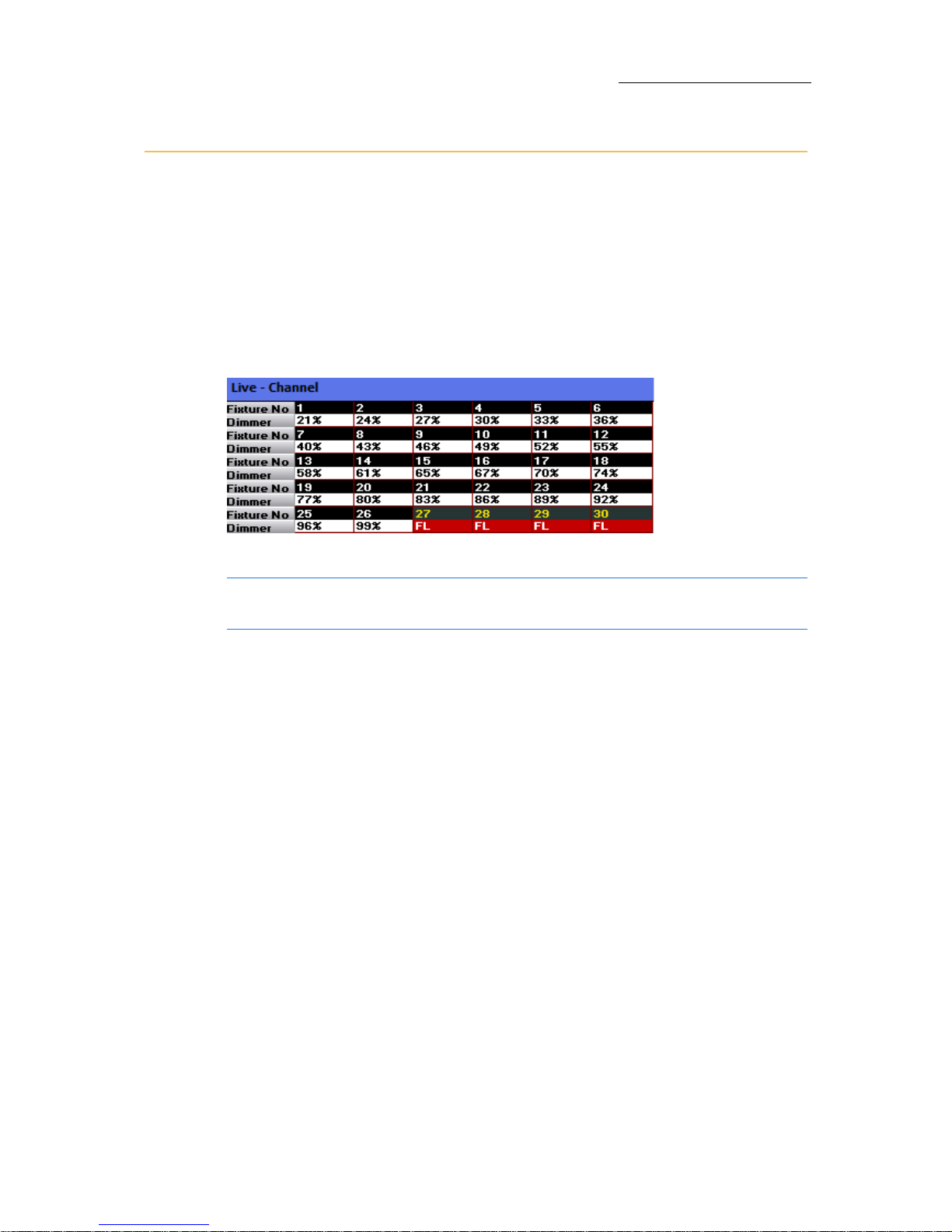
Live fixture display
Current fixture selections and values, as well as output from playback
devices, are shown in the live fixture display. The live fixture display is
in grid format.
To view the live fixture display
Go to the Workspace and choose Channel, Spot, Matrix, or Media Server under
the
Live node.
Figure 12: Live channel display with side headers
Tip! Use the tools in the LiveMode menu to control which fixtures are
displayed in the Live displays.
Page 48
42
Compulite
Chapter 3
Selecting fixtures
Fixtures are selected using console keys and the selection options
available on the
Editor tool bar.
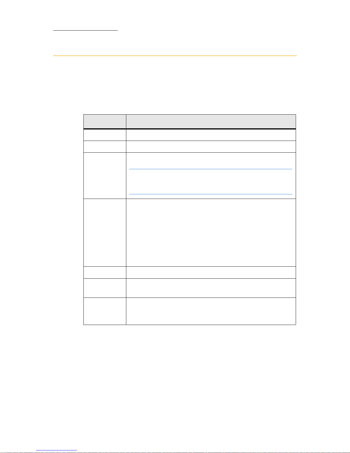
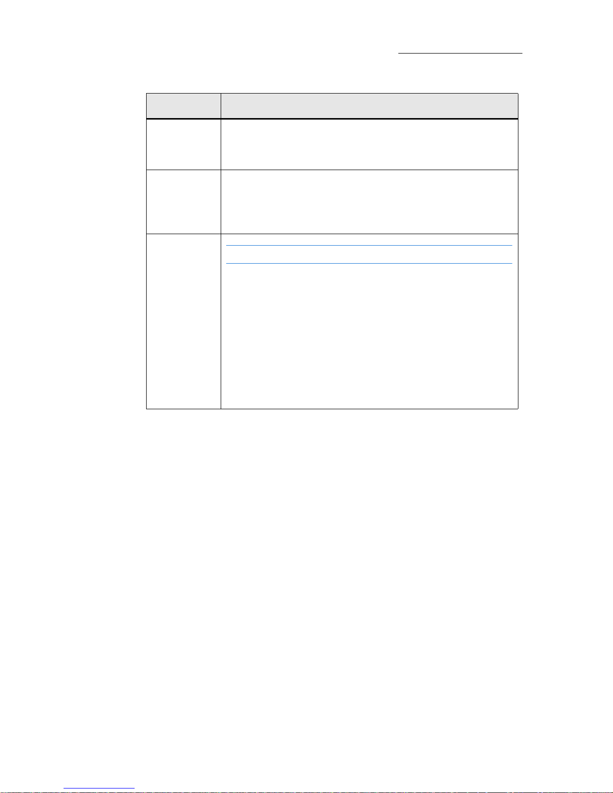
Using console keys for fixture selection
Key Name What it does
SPOT
Set the keypad for spot selection.
CHANNEL
Set the keypad for channel selection.
MATRIX /
MEDIA
SERVER
Set the keypad for selecting fixtures in the matrix set.
Note: SHIFT + MATRIX is used to access the Media server. If
you do not have a Matrix set patched then the default is
Media server.
GROUP /SET
Select fixtures using the set organizer by pressing SHIFT +
GROUP
Example:
SET0/ 1 12, selects channels 1 through 12.
SET 1/ 1 12, selects spots 1 through 12.
SET 2/ 100 200, selects fixtures in a matrix.
SET 3/ 1 12, selects media server devices 1 through 12.
0 - 9
Use for numeric entries.
‘Thru’ for range selections. Example:
SPOT, 1, , 24; selects
all the spots in the range.
+ (plus) Functions as an “and” key when used between fixture
selections. Example:
CHANNEL 1 + 3 + 7 + 11, selects channels
1, 3, 7, and 11.
Page 49
43
VECTOR
SELECTING AND CONTROLLING FIXTURES
— (minus) Used to remove a channel/spot form a range selection.
Example:
SPOT 1 5 — 4, selects channels 1, 2, 3, 5.
(dot)
or wheel
Makes the last selection available. Example: Before
pressing
RESET, the selection was spots 1, 3, 6, and 8.
Press
SPOT or move a parameter wheel to access the last
fixture selection.
Fixture
Note: This is not a key on the console panel.
When fixture numbers in the various sets do not overlap,
the command line numeric default is automatically set to
Fixture. When using this setup, it is not necessary to select a
set prior to selecting the fixture numbers.
Example:
Channels are numbered 1 100.
Spots are numbered 101 164.
To select (channel) 98, press 98 on the keypad; press 124
to select spot 124.
Key Name What it does
Page 50
44
Compulite
Chapter 3
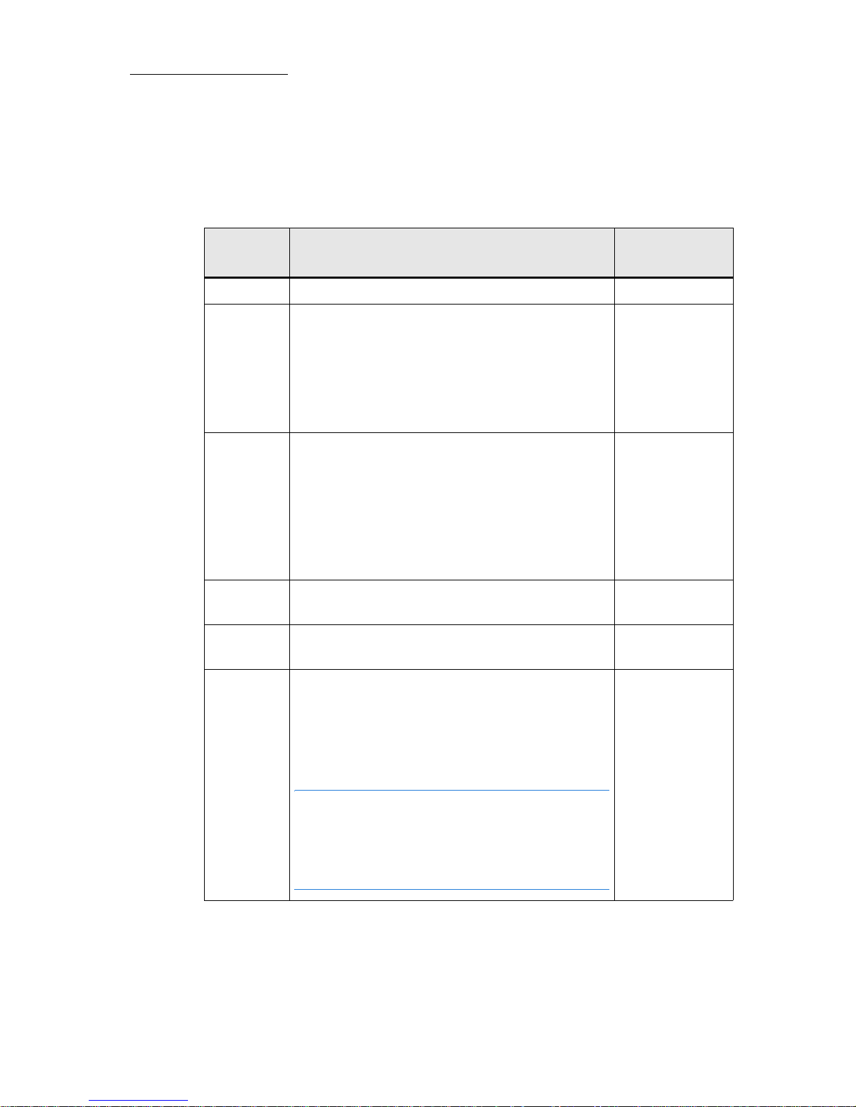
Using the Editor tool bar to filter fixture selection
The Editor tool bar provides fixture selection filters. Tapping EVERY
displays the selection filter options. The example shown here is
especially useful for television studio cyc lights.
BUTTON What it does
Console key
equivalents
EVERY
Opens filter options none
ODDS
Selects every other fixture, within the
designated range, starting with the first fixture.
Example 1: The range 1 thru 8 is selected. Tap
ODDS to select 1, 3, 5, and 7.
Example 2: The range 2 thru 8 is selected. Tap
ODDS to select 2, 4, 6, and 8.
none
EVENS
Selects every other fixture, within the
designated range, starting with the second
fixture.
Example1: The range 1 thru 8 is selected. Tap
EVENS to select 2, 4, and 6.
Example 2: The range 2 thru 8 is selected. Tap
EVENS to select 3, 5, and 7.
2
3RD
Selects every third fixture, within the
designated range, starting with the first fixture.
3
4TH
Selects every fourth fixture within the
designated range, starting with the first fixture.
4
/
Advance selection by a specified increment.
Example:
4 / 2, selects the second fixture in
each group of four fixtures.
Therefore:
CHANNEL 1 20 EVERY 4 / 2, selects
channels 2, 6, 10, 14, and 18.
Note: Even though the Tool bar buttons are
only up to 4th (every fourth fixture), you can
select 5th, 6th, etc. by choosing a number on
the keypad Example: 6/2, selects the second
fixture in each group of 6 fixtures.
/
Page 51
45
VECTOR
SELECTING AND CONTROLLING FIXTURES
Storing Fixture Groups
Groups are selection shortcuts. Groups can be combined and
manipulated like all other selection sequences. It is convenient to save
groups of fixtures that are related by type, function, or hanging
position.
Automatic groups
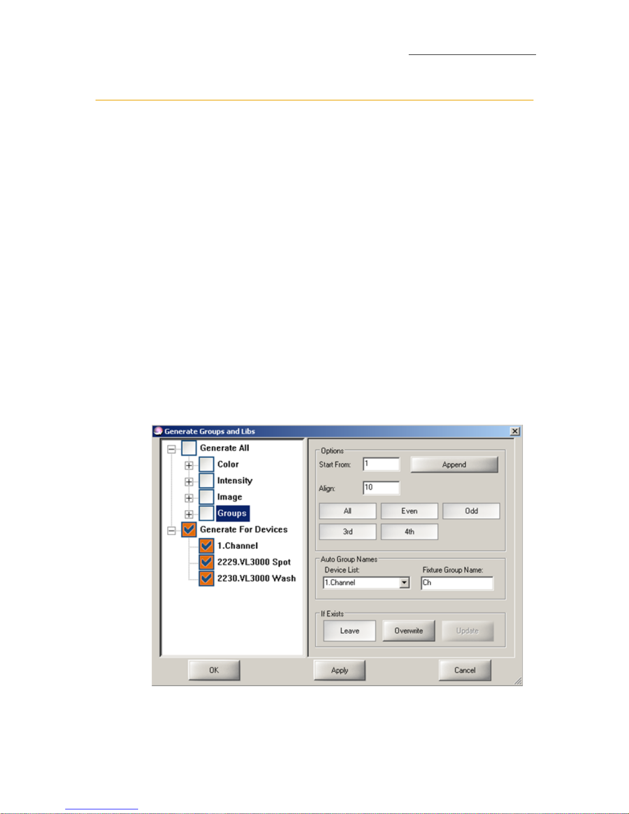
Through the Generate Groups and Libs dialog box, Vector automatically
generates fixture groups.
The automatic fixture group options for spots per device, channels,
scrollers, matrix set devices, and media server set devices, are:
All
Even
Odd
Every third - counting from the first fixture of a device type.
Every fourth - counting from the first fixture of a device type.
You can choose to generate groups for some or all of the fixtures used
in the show.
Figure 13: Generate libraries and groups dialog box
Page 52

46
Compulite
Chapter 3
You can number groups to your convenience in the dialog box’s
numbering area. The numbering option fields are:
If there are existing groups you can choose to:
Leave them as is
Overwrite them
Update them
To generate groups automatically
1. Open the To o ls menu and tap Generate Groups and Libs.
The dialog box opens.
2. Expand
Generate All.
3. Make sure
Groups is checked and selected.
When selected Groups appears on a dark field.
4. Expand
Generate for Devices and make sure the devices you want
organized into groups are checked.
5. Set the start number in the
Start from fields and the offset in the Align
field.
6. Select the type of group (
Even, Odd, All, 3rd, 4th).
7. Select the behavior (
Leave, Overwrite. or Update).
8. Ta p
APPLY.
Start From Store the first group to the number in this field and
sequentially increment the libraries or groups.
Align Choose an offset to leave space for groups that will be
stored later on. Generally, it is convenient to choose an
offset that corresponds to your display set up.
Example: Assume that you have sized the soft keys pane
to show 5 soft keys per row. You choose to generate 5
groups for each fixture type. If the start number is 1 and
the offset is 10, the generated groups will appear in every
other row.
Page 53

47
VECTOR
SELECTING AND CONTROLLING FIXTURES
User-defined groups
Groups can contain any number of fixtures and fixture types.
Groups retain the selection order. This is useful when planning groups
to use in effects.
Example: You can select spots in reverse order, for instance spots 26
24, 22, and 20, and save as a group. When recalling this group to use
in an effect, the first fixture selected (spot 26) is the first fixture
participating in the effect.
To store groups
Example: Store group 9 containing all fixtures used in an audience
sweep.
1. Select fixtures using any selection sequence.
2. Press
STORE
3. Ta p 9 on the group soft keys.
OR
1. Select fixtures using any selection sequence.
2. Press
GROUP and enter a number on the numeric keypad.
3. Press
STORE.
To add text tags to groups
1. Select the group.
2. Press
TEXT.
The
Te xt dialog box opens.
3. Use the keyboard to type the group’s name.
4. Press
STORE or tap OK.
The dialog box closes.
OR
Immediately after storing the group, press
TEXT and follow steps 3
and 4.
Page 54

48
Compulite
Chapter 3
To delete groups
1. Select the group or select more than one group: GROUP # #.
2. Press
DELETE.
The
Delete dialog box opens.
3. Press
DELETE again or tap DELETE in the dialog box.
To store groups
Example: Store group 9 containing all fixtures used in an audience
sweep.
1. Press
STORE.
2. Select fixtures using any selection sequence.
3. Ta p
9 on the group soft keys.
OR
1. Press
STORE.
2. Select fixtures using any selection sequence.
3. Press
GROUP and enter a number on the numeric keypad.
4. Press
ENTER.
To name a groups
1. Press TEXT.
2. Select the group.
3. Press ENTER.
The
Te xt dialog box opens.
4. Use the keyboard to type the library name.
5. Press
ENTER (on the console or the keyboard) or tap OK.
6. The dialog box closes.
OR
Immediately after storing the group, press
TEXT and follow steps 4
and 5.
Page 55

49
VECTOR
SELECTING AND CONTROLLING FIXTURES
To delete groups
1. Press DELETE.
2. Select the group or select more than one group:
GROUP # #.
3. Press
ENTER.
The
Delete dialog box opens.
4. Press
DELETE or ENTER again or tap DELETE in the dialog box.
OR
1. Press
DELETE.
2. Tap the group soft key.
3. Press
ENTER.
Page 56

50
Compulite
Chapter 3
Clearing the command line
The command line can be returned to its idle state or regressively
cleared, starting from the last entry.
To clear an entry (backspace)
Clear the command line entries in reverse order.
1. Press
CE.
The last entry is cleared.
2. Continue pressing
CE.
Each press clears the last entry in the command line.
To set the command line to idle
Press SHIFT + CLEAR.
All the entries in the command line are cleared.
Page 57

51
VECTOR
SELECTING AND CONTROLLING FIXTURES
Resetting the editor
To reset the editor
Press RESET.
All editor values are released in a 1 second fade (default) or according
to the default release time. Set default release time in the
System Settings
Timing
tab accessed through the Tools menu.
Press
RESET RESET quickly.
All editor values bump out.
Note: The last fixture selection remains active.
To reset the editor and clear the last fixture selection
Press SHIFT + RESET.
To clear selection without resetting the editor values
Press SHIFT + • (dot key)
Page 58
52
Compulite
Chapter 3
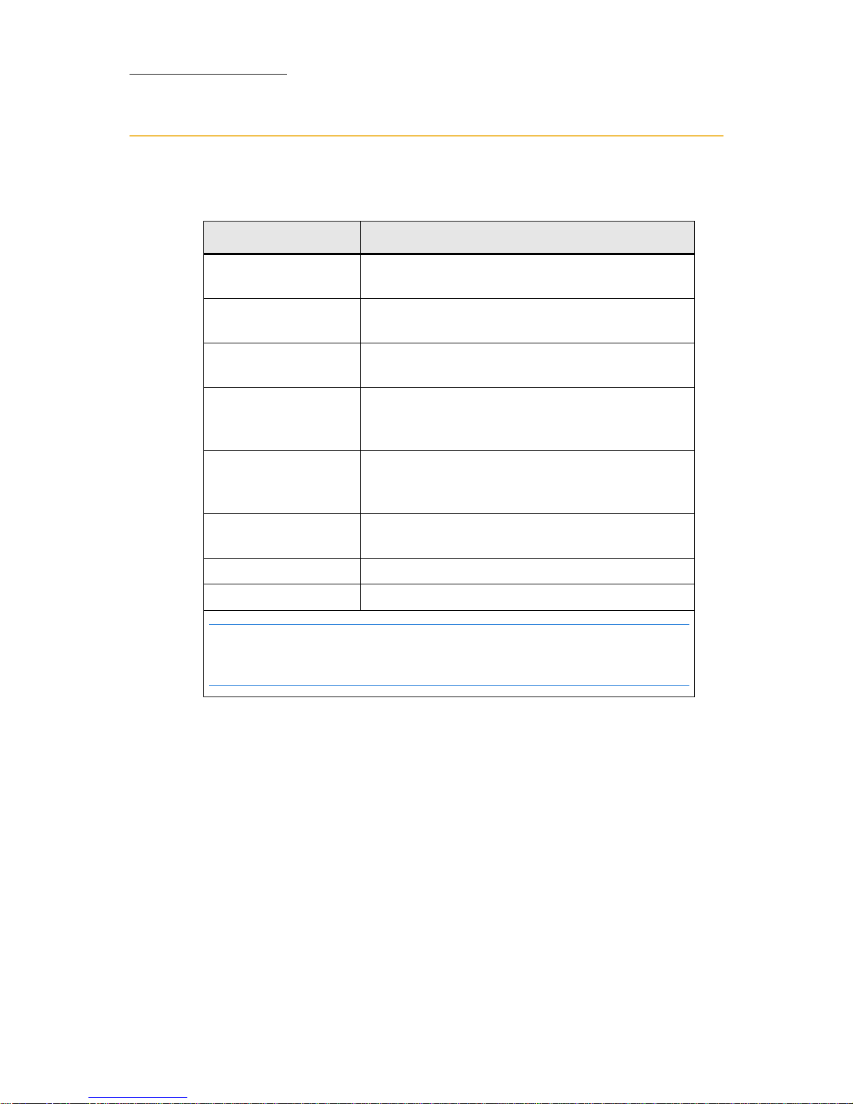
Output color code
The default color scheme for the console’s output shows the output
source:
Color What it means
Yellow Fixture numbers for fixtures that are active in
the editor.
Red Backround Values active in the editor and currently under
wheel control.
White Background Values in the editor, but not currently under
wheel control.
Blue Output from Master PB values that are higher
than those in the previous cue for the same
fixtures.
Green Master playback output values that are lower
than those in the previous cue for the same
fixtures.
Yellow Output from the playback devices (faders and
QKeys).
Purple Tracking in Master PB.
Red Redundant tracking in Master PB.
Note: Values displayed in white and red are the values normally included
when storing a cue. More specific store commands are available in the
Store Options dialog box; see the Vector Reference Guide.
Page 59
53
VECTOR
SELECTING AND CONTROLLING FIXTURES
Spot ignition
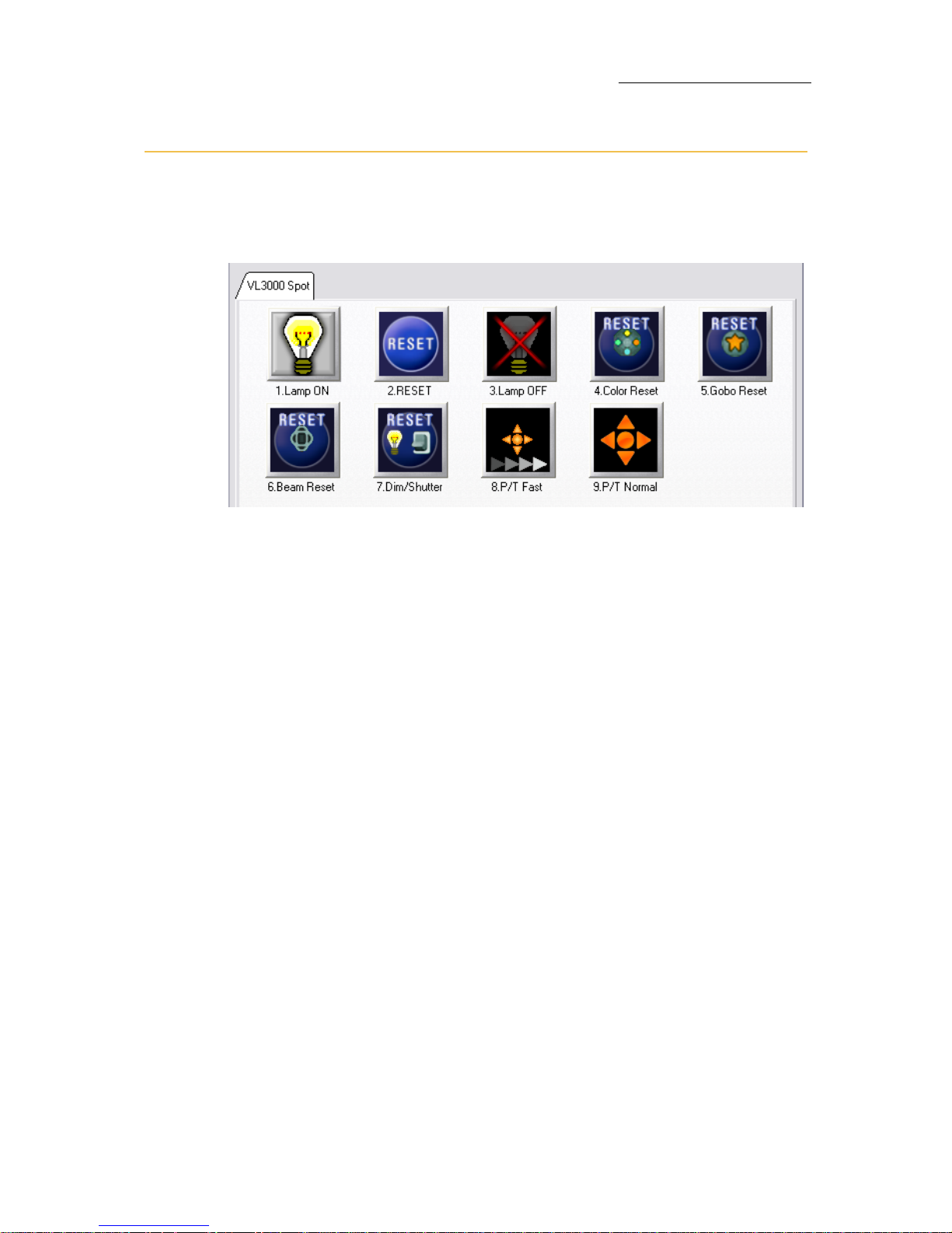
The Control picker allows access to all control features. The functions
available in the picker depend on the type of spot.
Figure 14: Typical Control picker
To turn the lamp on
1. Select the spots.
2. On the
Editor tool bar, tap CONTROL.
The
Control picker opens.
3. Ta p
LAMP ON and CLOSE.
To turn the lamp off
1. Select the spots.
2. On the
Editor tool bar, tap CONTROL.
The
Control picker opens.
3. Ta p
LAMP OFF and CLOSE.
To reset the fixture
1. Select the spots.
2. On the
Editor tool bar, tap CONTROL.
The
Control picker opens.
3. Ta p
RESET and CLOSE.
Page 60
54
Compulite
Chapter 3
Setting parameter values
The wheels, trackball, and console keys are used to set values for
moving light parameters and channel levels.
Parameter values are displayed in the live displays. The parameter’s
display format options are found under the
Format menu.
Using the wheels and wheel banks
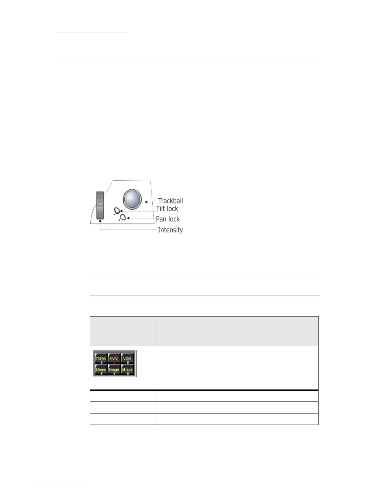
The vertical wheel controls the dimmer for all fixtures. The trackball
controls pan and tilt for moving devices. When fixtures do not have pan
and tilt parameters, such as Channels, the trackball will also function as
a dimmer wheel.
Figure 15: Vertical (intensity) wheel, trackball, pan and tilt locks
Parameters are organized, by type, into wheel banks.The five flat
encoders control all parameters including the dimmer, pan, and tilt.
ATTENTION! The Vector Violet has a 6th wheel which acts as a
dedicated dimmer wheel.
Wheel banks
(Parameter
types)
Possible parameters
Figure 16: Parameter (type) bank keys
INTENSITY
Dimmer, strobe
POSITION
Pan, tilt, movement speed
COLOR
Cyan, yellow, magenta, color wheels, color speed
Page 61
55
VECTOR
SELECTING AND CONTROLLING FIXTURES
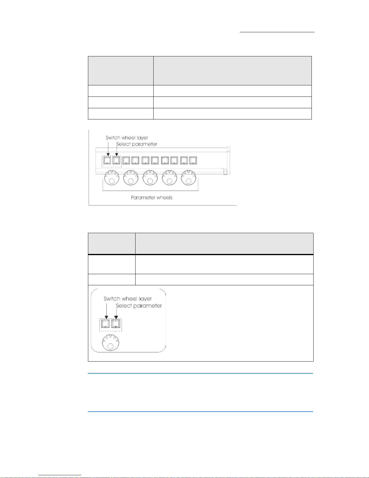
Figure 17: Parameter wheels, wheel layer keys, and parameter selection keys
Each parameter wheel has 2 associated keys:
ATTENTION! In Vector Violet you can select a parameter by clicking
on the wheel itself.
Double clicking on the wheel opens the picker for the parameters if the
picker exists (for example color wheel picker).
BEAM
Focus, zoom, iris
IMAGE
Gobo wheels, prism, gobo spin.
SHAPE
Framing shutters, frost
Parameter
wheel key
What it does
Left key Pages the bank layers when the parameter bank includes
more than 5 parameters.
Right key Selects the parameter.
Parameter wheel and the associated keys
Wheel banks
(Parameter
types)
Possible parameters
Page 62

56
Compulite
Chapter 3
To switch parameter banks
Press one of the parameter type keys: INTENSITY, POSITION, COLOR, BEAM,
IMAGE, or SHAPE.
To set intensity
1. Select the fixtures.
2. Use the vertical wheel.
Or
When the wheels are set to the intensity bank, use the flat encoder
that shows
Dimmer on its local display.
To set position
1. Select the fixtures.
2.
Use the trackball to set pan and tilt.
Or
When the wheels are set to the position bank, use the flat encoders
that show
Pan or Tilt on its local display.
Note: Keys for locking pan or tilt are adjacent to the trackball.
See ƒigure 15, page 54.
To set color, image, beam, and shape values
Parameters are pre-defined as either continuous parameters or step
parameters:
Continuous parameters wheel up from 0 (zr) to 100% (FL) with no
internal divisions.
Step parameters are defined with internal divisions. There can be
continuous control between steps or a step can transmit a preset
value. Steps are commonly used for parameters controlling both
dimmer intensity and strobe and with gobo wheels and color
wheels.
Continued on next page...
Page 63
57
VECTOR
SELECTING AND CONTROLLING FIXTURES
Example: Set color and image values.
1. Select the fixtures.
2. Press
COLOR to switch to the color wheel bank and use the
appropriate wheel to set the color value.
3. Press
IMAGE to switch to the image wheel bank and use the
appropriate wheel to set the value.
To move parameter steps
For absolute moves from step to step:
Use
, located on the Editor tool bar.
Setting values using pickers
Vector has preset pickers for gobo and color parameters. Pickers show
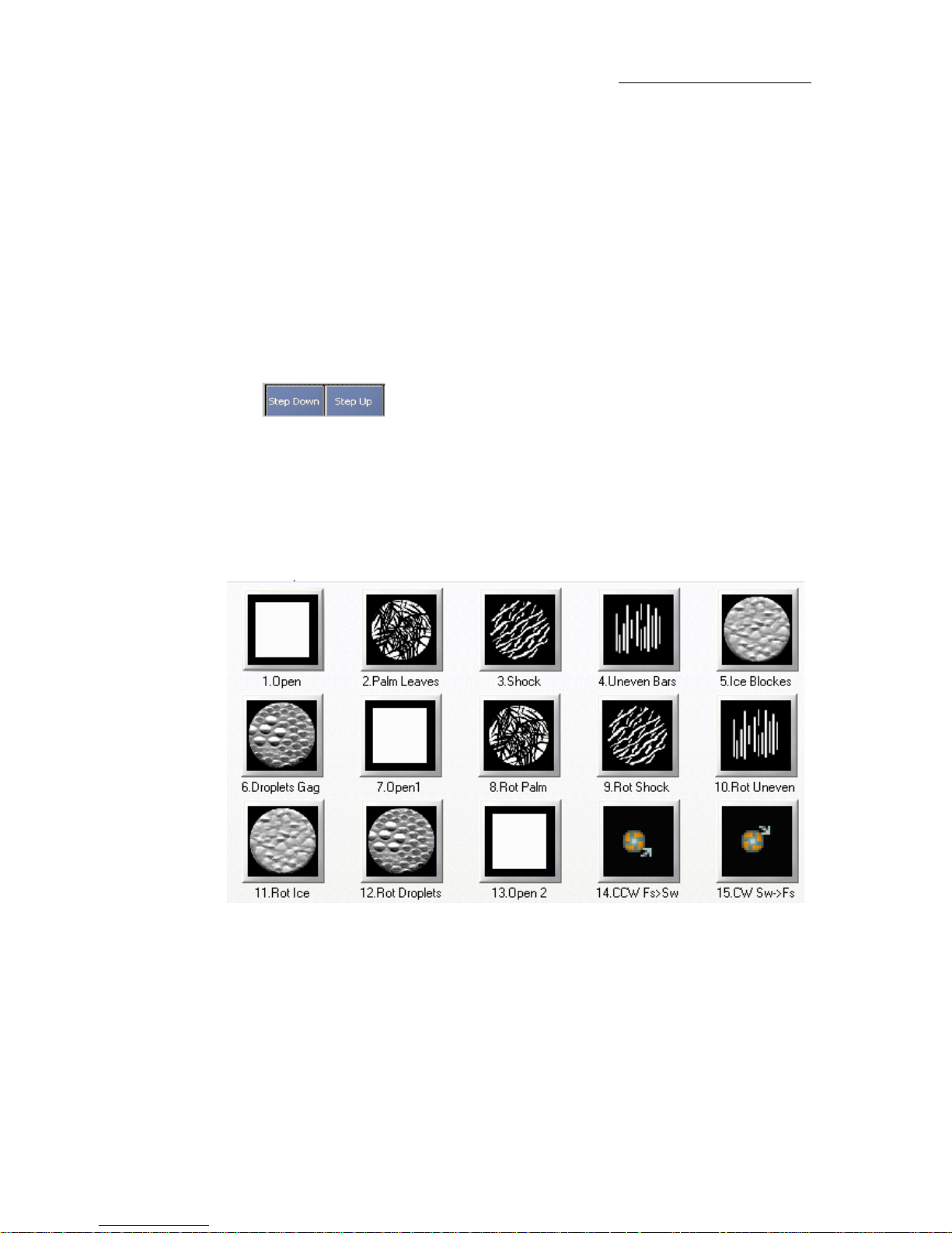
bitmaps that logically correspond to the steps.
Some pickers have more than one page. Use the
PREVIOUS and NEXT
buttons that appear in the picker to page.
Figure 18: Gobo picker
Page 64
58
Compulite
Chapter 3
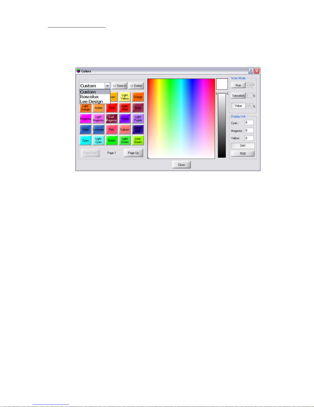
In color pickers, you can design your own custom color or choose colors
from the Roscolux and Lee Designers swatch book.
Figure 19: Color picker for designing custom colors or choosing colors from swatch
books
To set values with pickers
Example: Set the gobo
1. Select fixtures.
2. Press
IMAGE to switch to the gobo (image) bank
3. Double click
GOBO WHEEL in the Wheel Assignments display.
The gobo picker opens.
4. Tap the gobo of your choice.
The selection is immediately applied to the fixtures.
5. Click
CLOSE to close the Gobo Picker dialog box.
Or
Moving a wheel closes the picker.
Page 65

59
VECTOR
SELECTING AND CONTROLLING FIXTURES
Setting values using the keypad
Values can be set using the numeric keypad. Values are a percentage
from 0 - FL depending on the Value input method.
Note: Value input method is as follows:
European - Enter 1 digit for levels (example: 6 for 60%, 5.5 for
55%).
American - Enter 2 digits for levels (example: 60 for 60%).
Absolute values for parameters with steps, is a recognized as a
percentage value.
Example: Step 1 (0% - 50%) is dimmer and step 2
(51% - FL%) is strobe, the value 65% is within the strobe step.
Note: The following examples relate to American value input.
To set values using the numeric keypad
Example: Set dimmer at 60%, pan at 40, tilt at 35, and cyan at 20.
1. Select the fixtures.
2. Press
@, 60.
The dimmer intensity is set to 60%.
3. Press
POSITION, PAN, 40.
Pan is set to 40%.
4. Press
TILT, 35.
Tilt is set to 35%.
5. Press
COLOR, CYAN, 20.
Cyan is set to 20%.
Page 66

60
Compulite
Chapter 3
To set values using the numeric keypad
Example: Set dimmer at 60%, pan at 40, tilt at 35, and cyan at 20.
1. Select the fixtures.
2. Press
@, 60, ENTER.
The dimmer intensity is set to 60%.
3. Press
POSITION, PAN, @, 40, ENTER.
The position is updated with the new value.
4. Press
TILT, @, 35, ENTER.
The position is updated with the new value
5. Press
COLOR, CYAN, @, 20, ENTER.
The color is updated with the new value
Note: There are dedicated keys for FULL (100%), ON (50%), and ZERO
(zr).
Page 67

61
VECTOR
SELECTING AND CONTROLLING FIXTURES
Storing Libraries
Libraries are user-programmed or automatically generated presets of
parameter values. The library database is used as building blocks when
programming cues. Using libraries when programming cues makes
global updating of cues quick and accurate.
Example: The piano’s position has changed. Updating the piano
position library updates all occurrences of the library in all the cues.
Automatic libraries
Vector can automatically generate:
Color libraries
Intensity libraries
Image libraries
You can choose to generate some or all of these objects for some or all
of the devices used in the show.
Automatic libraries are generated in the
Generate Groups and Libs dialog
box.
To generate common color or image libraries for multiple
devices
1. Open the To o l menu.
2. Choose (tap)
Generate Groups and Libs.
The
Generate Groups and Libs dialog box opens.
3. Expand
Generate All.
4. Make sure
Color or Image are checked.
5. Ta p
Color or Image to select.
The item appears on a light field.
6. Set the start number in the
Start from fields and the offset in the Align
field.
7. Select the primary device from the drop down dialog menu.
8. Make sure the devices are checked under the
Generate for Devices list.
9. Select the behavior (
Leave, Overwrite. or Update).
10.Ta p
APPLY or OK.
The libraries are generated according to the primary device.
Page 68

62
Compulite
Chapter 3
Note: You can also generate separate color or image libraries for
different devices.
User-programmed libraries
To store a library
Example: Store color library 8.
1. Select the fixtures and set the color values.
2. Press
STORE.
3. Tap color library soft key
8.
OR
1. Select the fixtures and set the color values.
2. Press
COLOR and 8.
3. Press
STORE.
To add text tags to libraries
1. Select the library.
2. Press
TEXT.
The
Te xt dialog box opens.
3. Use the keyboard to type the library name.
4. Press
STORE or tap OK.
The dialog box closes.
OR
Immediately after storing the library, press
TEXT and follow steps 3
and 4.
To delete libraries
1. Select the library.
2. Press
DELETE.
The
Delete dialog box opens.
3. Press
DELETE again or tap DELETE in the dialog box.
Page 69

63
VECTOR
SELECTING AND CONTROLLING FIXTURES
To store a library
Example: Store color library 8.
1. Select the fixtures and set the color values.
2. Press
ENTER.
The values are output.
3. Press
STORE.
4. Tap an available space on the color library soft keys.
OR
1. Select the fixtures and set the color values.
2. Press
ENTER.
The values are output.
3. Press
STORE.
4. Press
COLOR and 8.
5. Press
ENTER.
To add text tags to libraries
1. Press TEXT.
2. Select the library.
3. Press
ENTER.
The
Te xt dialog box opens.
4. Use the keyboard to type the library name.
5. Press
ENTER or tap OK.
The dialog box closes.
OR
Immediately after storing the library, press
TEXT and follow steps 4
and 5.
To delete libraries
1. Press DELETE.
2. Select the library.
Continued on next page...
Page 70

64
Compulite
Chapter 3
3. Press ENTER.
The
Delete dialog box opens.
4. Press
DELETE or ENTER again.
Or
Tap
DELETE in the dialog box.
OR
1. Press
DELETE.
2. Tap the library soft key.
3. Press
ENTER.
Using libraries for programming cues
Using libraries to build lighting looks makes cue editing easier, quicker,
and more accurate.
Use of position libraries is particularly important since updating libraries
globally updates the cues programmed with libraries. If your show
moves to a new venue, updating your position libraries ensures that the
positions in cues will be on the mark.
More than one library can be selected and then applied simultaneously
to the fixtures.
To program a cue using libraries selected via soft keys
Example: Program a cue using position library 5.
1. Select the fixtures.
2. Switch to the position library tab.
3. Ta p
5 on the position library soft keys.
The pan and tilt values are set according to the values stored in the
library. The library icon is displayed in the pan and tilt cells.
4. Store the cue.
To program a cue using libraries selected on the keypad
Example: Apply position library 5, color library 3, and image library 1
to selected fixtures
1. Select the fixtures.
2. Press
POSITION and enter 5 on the numeric keypad.
Continued on next page...
Page 71

65
VECTOR
SELECTING AND CONTROLLING FIXTURES
3. Press ENTER.
The pan and tilt values are set according to the values stored in the
library. The library icon is displayed in the pan and tilt cells.
4. Press
COLOR and enter 3 on the numeric keypad.
5. Press
ENTER.
The color values are set according to the values stored in the
library.The library icon is displayed in the relevant parameter cells.
Press IMAGE and enter 1 on the numeric keypad.
6. Press
ENTER
The image values are set according to the values stored in the
library. The library icon is displayed in the relevant parameter cells.
7. Store the cue
To apply multiple libraries simultaneously
Example: Select position library 1, color library 3, and image library 5
and then apply them to the selected fixtures.
1. Select fixtures.
2. Press
POS and 1 to select position library 1 (or use any other library
selection procedure).
3. Press
COLOR and 3 to select color library 3 (or use any other library
selection procedure).
4. Press
IMAGE and 5 to select image library 5 (or use any other library
selection procedure).
5. Press
ENTER.
All of the selected libraries are applied to the fixtures.
Page 72

66
Compulite
Chapter 3
Page 73

67
Chapter 4 Programming and Updating
Cues
In this chapter you learn how to:
Create QLists
Store cues
Delete cues
Set cue fade times
Update cues
Blind Mode
Page 74

68
Compulite
Chapter 4
QLists
All cues are organized into QLists.
QLists can be loaded to all playback devices - AB crossfader, playback
faders, and QKeys.
All cues are stored to the default QList, which is the QList loaded on the
master playback device, unless otherwise instructed. The default
master playback is the AB crossfader, but any playback device can be
designated as the master playback.
Page 75
69
VECTOR
PROGRAMMING AND UPDATING CUES
Cues
Cues are always organized in QLists. The values stored in cues are
normally the editor values that are displayed in red or white. Cues can
be numbered from 0.01 to 9999.99.
Programming cues consists of:
Selecting fixtures
Setting parameter values
Setting the fade times
Storing the resulting lighting state as a cue in a QList.
Storing QLists and cues
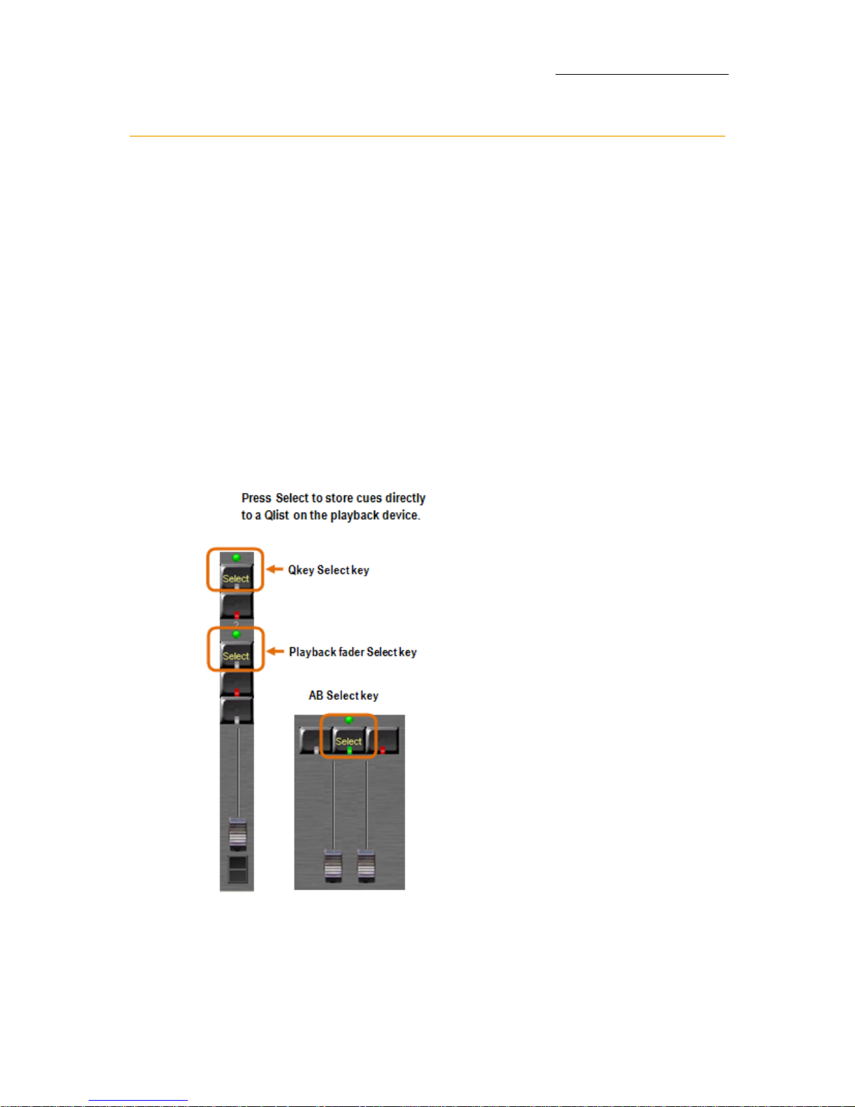
Use the SELECT key to create QLists and store cues. The lighting state
can be stored as a cue in more than one QList. All that is necessary to
do is to press
SELECT for each QList.
Figure 20: Select keys for playback devices
Page 76

70
Compulite
Chapter 4
To create a new QList
Example: Create QList 1on the AB crossfader.
1. Press
QLIST and 1 on the numeric keypad.
2. Press
SELECT for AB.
The command line shows:
Playback AB Assigned. QList 1 is loaded to
AB.
To store cues to the master playback device
Example: Store cue 1 to QList 1 that is loaded on the AB crossfader
and is the default master playback device.
1. Select fixtures and set values.
2. Press
CUE and enter a cue number on the numeric keypad.
3. Press
STORE.
The cue is automatically added to the QList on the master playback.
The command line shows:
Playback AB Assigned: QList 1 Cue 1 Stored.
4. Store the next cue by selecting fixtures, setting values, and
pressing
STORE, SELECT.
Or
Press
STORE+.
The editor is stored as cue 2.
To store point cues
Example: Store cue 2.5 in QList 1 that is on the AB playback.
1. Select fixtures and assign values.
2. Press
STORE.
3. Press
2 5.
4. Press
SELECT.
The command line shows:
Playback AB Assigned: QList 1 Cue 2.5 Stored.
Cue 2.5 is output from AB.
Page 77

71
VECTOR
PROGRAMMING AND UPDATING CUES
To store cues to the master playback device
Example: Store a cue to the default QList (the QList loaded to the
master playback).
1. Select fixtures and set values.
2. Press
ENTER.
The values are output.
3. Press
STORE.
4. Press
CUE and enter a cue number on the numeric keypad.
5. Press
ENTER.
The cue is automatically added to the QList on the master playback.
OR
1. Select fixtures and assign values.
2. Press
ENTER.
The values are output.
3. Press
STORE +.
The editor is stored to the next available cue number. It is displayed
in the command line with the QList number for the cue on the
master playback.
To add cues to the QList on the master playback device
Example: Store a new cue to the default QList (the QList loaded to the
master playback).
1. Select fixtures and set values.
2. Press
ENTER.
The values are output.
3. Press
STORE +.
The editor is stored to the next available cue number. It is displayed
in the command line with the QList number for the cue on the
master playback.
OR
1. Select fixtures and set values.
Continued on next page...
Page 78

72
Compulite
Chapter 4
2. Press ENTER.
The values are output.
1. Press
STORE.
2. Press
CUE and press NEXT.
The next available cue number is displayed in the command line
with the QList number for the cue on the master playback.
3. Press
ENTER.
The cue is automatically added to the QList on the master playback.
To store point cues
Example: Store cue 2.5 in QList 1 that is on the AB playback.
1. Select fixtures and assign values.
2. Press
ENTER.
3. Press
STORE.
4. Press
2 5.
5. Press
SELECT.
The command line shows:
Playback AB Assigned: QList 1 Cue 2.5 Stored.
Cue 2.5 is output from AB.
IMPORTANT! In Compulite mode, storing a cue does not clear the
editor and the cue is not output from the playback device.
In tracking mode, storing a cue clears the editor. The stored cue is
immediately output from the playback device.
Page 79

73
VECTOR
PROGRAMMING AND UPDATING CUES
Deleting cues
Individual cues or a range of cues from a single QList can be deleted
from the show.
To delete a cue
Example: Delete cue 9 from QList 1.
1. Select Qlist 1 cue 9.
2. Press
DELETE.
The Object Exists dialog box is displayed.
3. Press
DELETE again.
Or
Tap
DELETE in the dialog box.
Deleted, displayed in the command line confirms a successful
deletion.
To delete a cue
Example: Delete cue 9 from QList 1.
1. Press
DELETE.
2. Select Qlist 1 cue 9.
3. Press DELETE or ENTER.
The
Delete confirmation box is displayed.
4. Press
DELETE or ENTER again.
Or
Tap DELETE in the dialog box.
Deleted, displayed in the command line confirms a successful
deletion.
Page 80
74
Compulite
Chapter 4
Assigning fade times to cues
If no fade times are set, the cue default time is automatically assigned.
The default cue time can be changed in
To ol s System Settings Timing.
If no time-out is set it defaults to the time-in setting.
Use
0 to set a cut (bump) time.
Time settings Function
TIME
Sets the Editor tool bar to cue time mode.
Prepares to set fade times for the current cue on the
master playback device.
TIME IN
On Go, all the fixtures fading to higher values begin their
fade. The fade takes place in the set time.
TIME OUT
On Go, all the fixtures fading to lower values begin their
fade. The fade takes place in the set time.
DELAY IN
On Go, all the fixtures fading to higher values begin to
count the delay time before beginning their fade.
DELAY OUT
On Go, all the fixtures fading to lower values begin to
count the delay time before beginning their fade.
WAIT
Pressing WAIT opens two options on the Editor tool bar:
FOLLOW ON and MANUAL.
If you set a wait time (
WAIT #), the cue is automatically
tagged as a follow-on cue.
FOLLOW ON
Fade to the next cue without waiting for a Go command.
“Follow on” of the next cue starts X second after current
cue is entetring
MANUAL
Wait for a Go command before fading to the next cue.
Manual is the default setting for all cues.
Page 81
75
VECTOR
PROGRAMMING AND UPDATING CUES
To set fade times when programming a cue
Example: Add fade times when programming QList 1 cue 5.
1. Select fixtures and set values.
2. Select QList 1 and cue 5.
3. Press
TIME.
The
Editor tool bar is now in time mode.
4. To set time-in, press
4.5 on the numeric keypad.
5. Press
DELAY IN and 3 on the numeric keypad.
6. Press
DELAY OUT and 2 on the numeric keypad.
7. Press
STORE.
To set fade times when programming a cue
Example: Add fade times when programming QList 1 cue 5.
1. Select fixtures and set values.
2. Press
ENTER.
3. Press
STORE.
4. Select QList 1 and cue 5.
5. Press
TIME.
The
Editor tool bar is now in time mode.
6. To set time-in, press
4.5 on the numeric keypad.
7. Press
DELAY IN and 3 on the numeric keypad.
8. Press
DELAY OUT and 2 on the numeric keypad.
9. Press
ENTER.
Time: Time in Time out Delay in Delay out Wait
Set to:
4.5 Default (4.5) 3.0 2.0 Manual
Time: Time in Time out Delay in Delay out Wait
Set to:
4.5 Default (4.5) 3.0 2.0 Manual
Page 82
76
Compulite
Chapter 4
To set time-in and time-out
Example: Set time-in to 5 and time-out to 10.
(QLIST #), CUE #, TIME, 5, / (slash), 10, STORE
(QLIST #), CUE #, TIME, 5, / (slash), 10, ENTER
To set delay-in and delay-out
Example: Set delay-in to 3 and delay-out to 5.
(QLIST #), CUE #, TIME, DELAY-IN, 3, / (slash), 5, STORE
(QLIST #), CUE #, TIME, DELAY-IN, 3, / (slash), 5, ENTER
To set a follow on cue
Example: The fade to cue 3 automatically begins when cue 2
completes its fade.
(QLIST #), CUE 2, TIME, WAIT, FOLLOW-ON, STORE
(QLIST #), CUE 2, TIME, WAIT, FOLLOW-ON, ENTER
Note: The follow-on setting, which begins an automatic fade to cue 3,
is set in cue 2.
To set a counted wait time
Example: Set a wait time of 3 seconds for cue 5. The fade from cue 5
to cue 6 will be automatic.
CUE 5, TIME, WAIT, 3, STORE.
CUE 5, TIME, WAIT, 3, ENTER.
Cue 6 automatically becomes a follow-on cue. When cue 5 starts there is 3
second wait and cue 6 begins its fade.
Page 83

77
VECTOR
PROGRAMMING AND UPDATING CUES
Multiple QLists
While programming a show, you may have a number of Qlists loaded to
different playback devices. Storing cues to the different QLists is done
as described in Storing QLists and cues
(see page 69).
Note: The QList located on the master playback device is the default
QList. This means that unless you specify a Qlist when storing a cue,
the new cue is stored to the default QList. See:“
Master Playback” on
page 94.
To store a cue to any playback device
Example: Store cue 1 in QList 11. QList 11 is resident in fader 6.
1. Select fixtures and assign values.
2. Press
STORE.
3. Press
SELECT for fader 6.
The command line shows:
Playback 1/6: QList 11 Cue 1 Stored.
OR
1. Select fixtures and assign values.
2. Press
QLIST 11.
3. Press
CUE 1.
4. Press
STORE.
The command line shows:
Playback 1/6: QList 11 Cue 1 Stored.
To add cues to the QList on any playback device
Example 1: Store cue 2 (the next available cue number) in QList 11,
loaded on fader 6. The next cue number is the current cue incremented
by one.
1. Select fixtures and assign values.
2. Press
STORE
3. Press
SELECT for fader 6.
The command line shows:
Playback 1/6: QList 11 Cue 2 Stored.
Page 84

78
Compulite
Chapter 4
To store a cue to any playback device
Example: Store cue 1 in QList 11. QList 11 is resident in fader 6.
1. Select fixtures and assign values.
2. Press
ENTER. The values are output.
3. Press
STORE.
4. Press
SELECT for fader 6.
The command line shows:
Playback 1/6: QList 11 Cue 1 Stored.
OR
1. Select fixtures and assign values
2. Press
ENTER. The values are output.
3. Press
STORE.
4. Select
QLIST 11. Skip this step if you are storing this cue to the
master playback.
5. Press
CUE, 1.
6. Press
ENTER.
The command line shows: Playback 1/6: QList 11 Cue 1 Stored.
To add cues to the QList on any playback device
Example 1: Store cue 2 (the next available cue number) in QList 11,
loaded on fader 6. The next cue number is the current cue incremented
by one.
1. Select fixtures and assign values.
2. Press
ENTER. The values are output.
3. Press
STORE.
4. Press SELECT for fader 6.
The command line shows:
Playback 1/6: QList 11 Cue 2 Stored.
Page 85
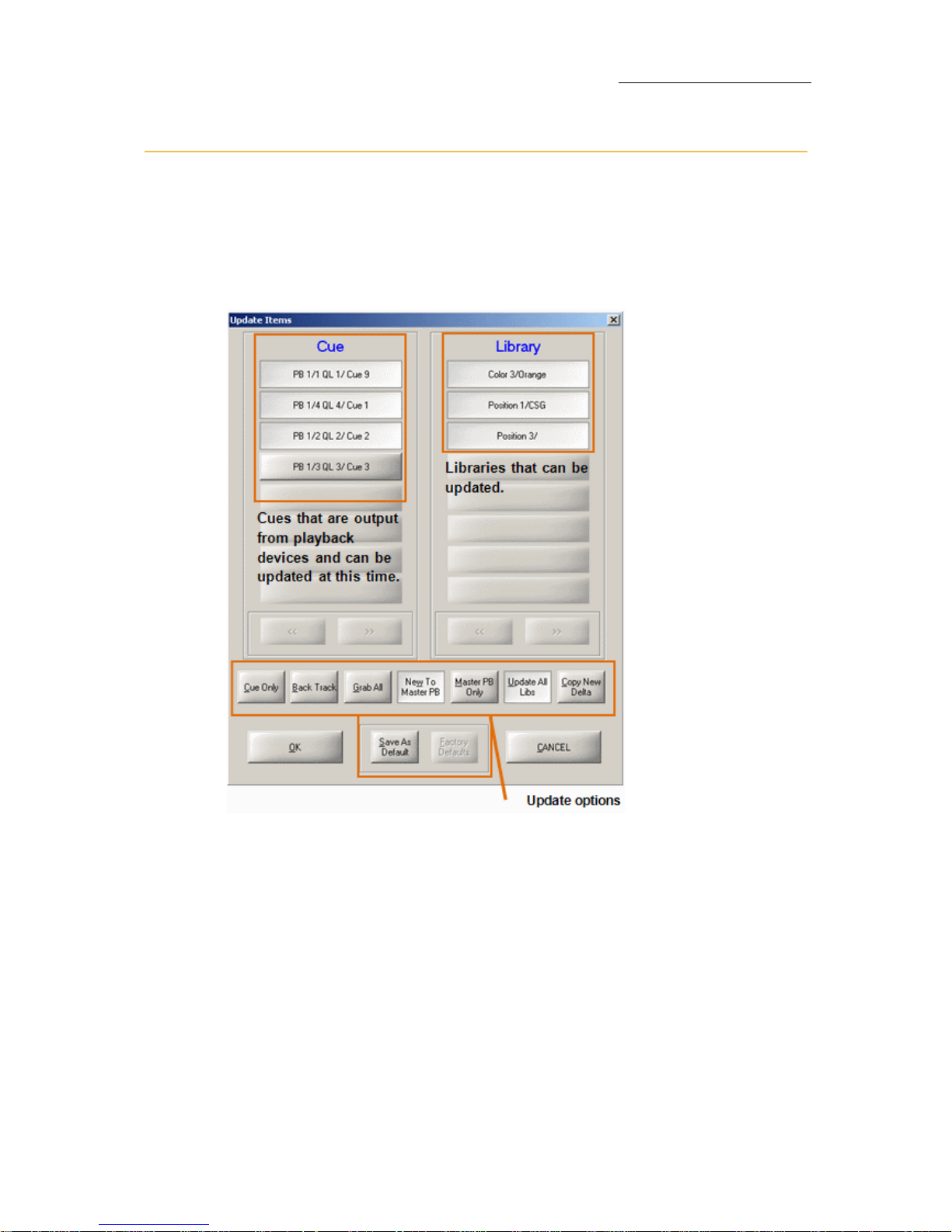
79
VECTOR
PROGRAMMING AND UPDATING CUES
Updating cues
Edit cues using the UPDATE or STORE keys. As a rule of thumb, use
UPDATE to edit cues that are output from one of the playback devices.
Use
STORE for cues that are not output on a playback device.
Pressing
UPDATE when editing cues, opens the Update Items dialog box.
Figure 21: Update Items dialog box
The cues, which are currently output from a playback device and will be
changed by completing the update command, are listed in the
Cue
column. Libraries that can be updated are listed in the
Library column.
The buttons at the bottom of the dialog offer options to filter the update
command.
Page 86
80
Compulite
Chapter 4
Using the Update dialog box options:
Option What it does
GRAB ALL New values can be stored to cues currently output
from playback devices, on the condition that the cues
are selected in the Cue column.
NEW TO MASTER PBNew values are stored in the cue output from the
master playback. This is the default.
MASTER PB
ONLY
Updates the cue on the master playback only.
UPDATE ALL
LIBS
Updates all libraries where appropriate. The relevant
libraries are displayed in the library column.
COPY NEW
DELTA
Copy the values active in the editor to the clipboard
and use as a delta..
CUE ONLY
(Tracking mode)
The updated value(s) are for the current cue only.
When fading to the next cue the updated values
return to the tracked value.
BACK TRACK
(Tracking mode)
Change the value(s) in all the previous cues.
To update cues using back track
Example: Channel 1 is tracking through the cues at
70%. Update cue 5 for channel 1 at 35% and update
the previous cues (cues 1 - 4) with same value.
1. Select channel 1 and set the intensity to 35%.
2. Press UPDATE. The update items dialog box opens.
3. Ta p B A C K T R A C K .
4. Tap OK. The value for channel 1 is updated in cues
1 - 5.
SAVE AS
DEFAULT
By using this option you are guaranteed that the Item
selected from the Update Items box remains saved as
the Default.
FACTORY
DEFAULTS
The Factory Defaults button returns the options in the
Update Items dialog box to their factory Default value
which is New to Master PB and Update All Libs options
selected.
Page 87

81
VECTOR
PROGRAMMING AND UPDATING CUES
To update cues
1. Select the fixtures and adjust the values.
2. Press
UPDATE.
The
Update Items dialog box opens.
3. Press
SELECT for the playback device where the cue is output.
OR
1. Select the cue, select the fixtures, (
CUE #, CHANNEL/SPOT #) and
adjust the values.
2. Press
STORE.
The cue is stored with the new values.
ATTENTION! Using UPDATE also, by default, updates libraries. If you do
not want to update libraries now, deselect
UPDATE ALL LIBS in the Update
dialog box
Page 88

82
Compulite
Chapter 4
Blind Mode
You can program and update cues in the blind Mode. When the blind
mode is active, the fixture values in the live editors are not output.
When
BLIND is active it is indicated in the command line:
Using the blind editor
To activate the blind editor
Press BLIND.
The key’s LED is on.
To store cues in blind mode
1. Press BLIND to switch to the blind editor.
2. Select fixtures and assign values.
3. Use any store sequence, including
STORE, SELECT.
Note: When storing a cue in blind mode, the playback device does not
advance to the new cue.
To exit the blind editor
Press BLIND.
The key’s LED turns off and the blind editor indication is removed from
the command line.
Page 89

83
VECTOR
PROGRAMMING AND UPDATING CUES
Blind editing for incoming cues
This feature provides quick, blind editing of the incoming cue. When
editing is completed, exiting the blind editor is automatic.
To edit the incoming cue in the blind editor
1. Ta p BLIND PB PREVIEW EDIT.
The blind editor is now active.
2. Press
SELECT for the playback outputting the cue.
The contents of the next (incoming) cue are active in the editor.
The command line shows the QList, cue number, and fixtures in cue.
Example:
QList 3, cue 6, channel 3 14, spot 1 12.
3. Select fixtures and set parameter levels.
4. Press
STORE.
To edit the incoming cue in the blind editor
1. Ta p BLIND PB PREVIEW EDIT.
The blind editor is now active.
2. Press
SELECT for the playback outputting the cue.
The contents of the next (incoming) cue are active in the editor.
The command line shows the QList, cue number, and fixtures in cue.
Example:
QList 3, cue 6, channel 3 14, spot 1 12.
3. Select fixtures and set parameter levels.
4. Press UPDATE, then ENTER
The incoming cue is updated and the blind editor closes.
Page 90

84
Compulite
Chapter 4
Page 91

85
Chapter 5 Playback
In this chapter you learn how to:
Load QLists to playback devices
Free playback devices
Use the Master Playback device
Release playback devices
Use snaps
Convert temporary cues to cues in QLists
Page 92
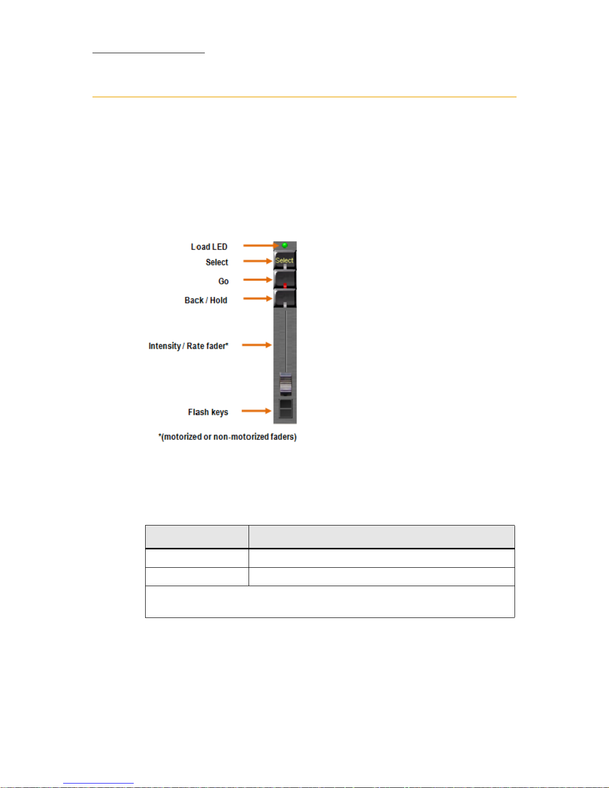
86
Compulite
Chapter 5
Playback devices
Vector's playback devices are:
AB crossfader
Faders
QKeys
Faders
Figure 22: Playback fader and its function keys. Default functions are shown in this
illustration.
Fader playback controls
Fader control Function options
Programmable keys Go, Back, and Flash
Slider (fader) Default function is intensity master
Key and slider functions can be changed in Playback Properties dialog box
PBD tab.
Page 93
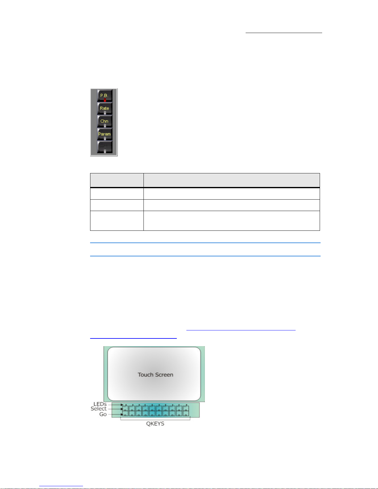
87
VECTOR
PLAYBACK
Fader modes
Faders also have different working modes.
Figure 23: Mode keys are located to the left of the faders
ATTENTION! Fader modes are global, affecting all the faders.
Qkeys
Qkeys, located below the touch screens, are playback devices without a
fader. Each QKey has an associated select key and one programmable
control key. The default control key command is Go. This can be
changed in the
Playback dialog box Playback Definitions tab.
For Vector Violet - please see Vector Violet Playback and Q-Key
functionality (see page 91)
Figure 24: Qkeys
Mode What it does
PB (Playback) The faders are intensity masters.
RATE
The faders are rate masters.
CHN (Channel) Each fader controls one channel. Channel pages are
unlimited.
Page 94
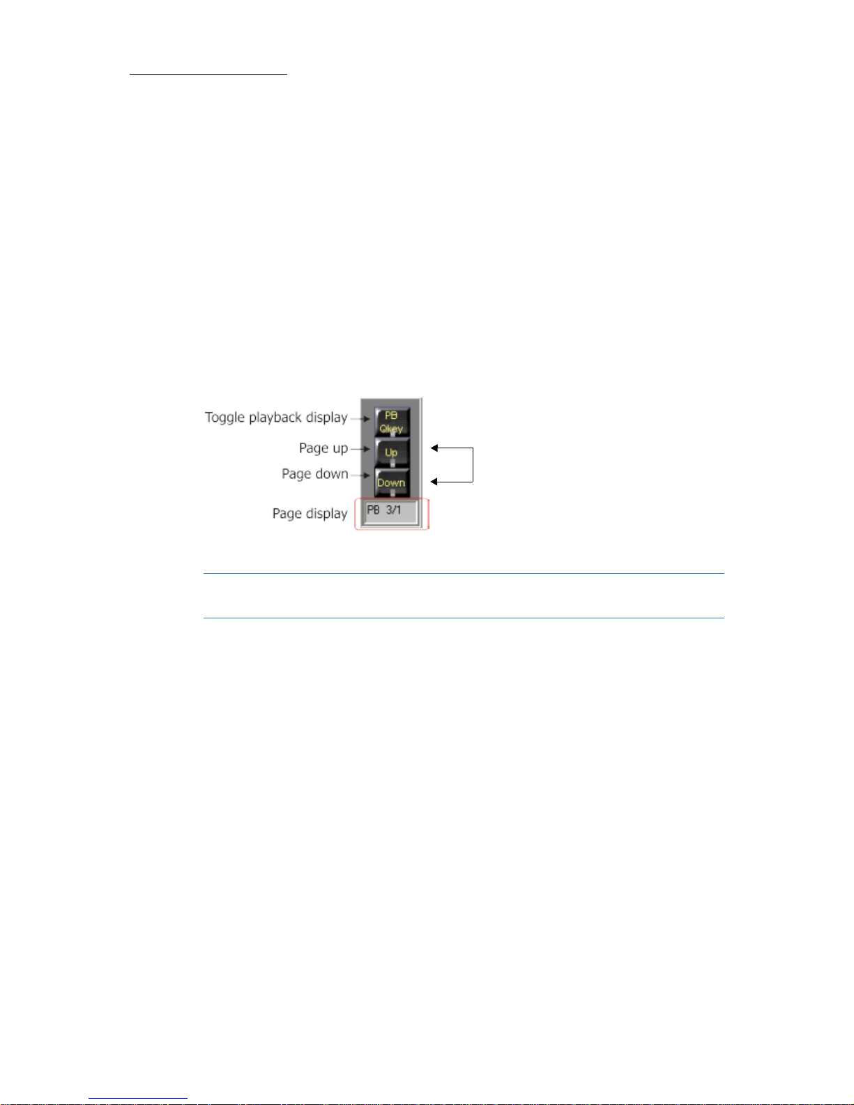
88
Compulite
Chapter 5
Paging faders and Qkeys
There are 5 fader pages and 5 Qkey pages for Vector Red and Vector
Violet. There are 10 fader pages and 10 Qkey pages for Vector Blue,
Green and Vector Orange and Vector PC.
This comprises 100 playback faders and 100 Qkeys per snap.
To page faders
Arrow UP to page up; the page number appears in the faders' LCD
display and on the playback wing displays.
Arrow
DOWN to page down; the page number appears in the faders' LCD
display and on the playback wing displays.
Figure 25: Playback device (faders and QKeys) paging controls
Note: When paging the playback wing faders, the QKeys are also
paged in the background.
To page Qkeys
Press PB/QKEY DISPLAY to toggle the playback wing and use the arrow
keys. The page number appears in the LCD display and on the playback
wing displays.
Note: On the actual
console the up and
down keys are
represented by arrows.
Page 95
89
VECTOR
PLAYBACK
Loading and releasing playback devices
All playback devices have a SELECT key. This key allows loading a Qlist
or a temporary cue and also serves to commission the master playback
device. Each
SELECT key has a green LED. When the playback device is
the master playback the LED is on.
Note: There can be only one (1) master playback.
Each playback device has a LED above the
SELECT key. The LED color
represents assignment types.
To load a Qlist to a playback device
1. Choose the Qlist: QLIST #.
2. Press
SELECT for a playback device. The Qlist is loaded to the
selected device. The LED above
SELECT is lit.
To load a range of QLists
Select the QLists (QLIST # #) and press SELECT for a playback device.
The selected QLists are loaded to consecutive playbacks.
ATTENTION! If the selected range contains more QLists than the
playback devices available on the current page, the remainder is loaded
to the next page.
Example: The selected range of QLists is 1 through 15 with QList 1
loaded to playback 1on page 1; QLists 11 through 15 will be loaded to
playbacks 1 through 5 on page 2.
LED Color Assignment Type
Green QList
Red Chaser
Orange Temporary cue Te m pora r y Cue s
(see
page 103)
Page 96

90
Compulite
Chapter 5
To free playback devices
To free one playback:
FREE, SELECT; the LED above the SELECT key is extinguished.
To free all the playback devices:
Press
SHIFT + FREE.
Note: A double hit on FREE locks the key. When the key is locked, press
as many SELECT keys as needed.
To free all playback devices except the Master PB
FREE + (Arrow key).
Page 97
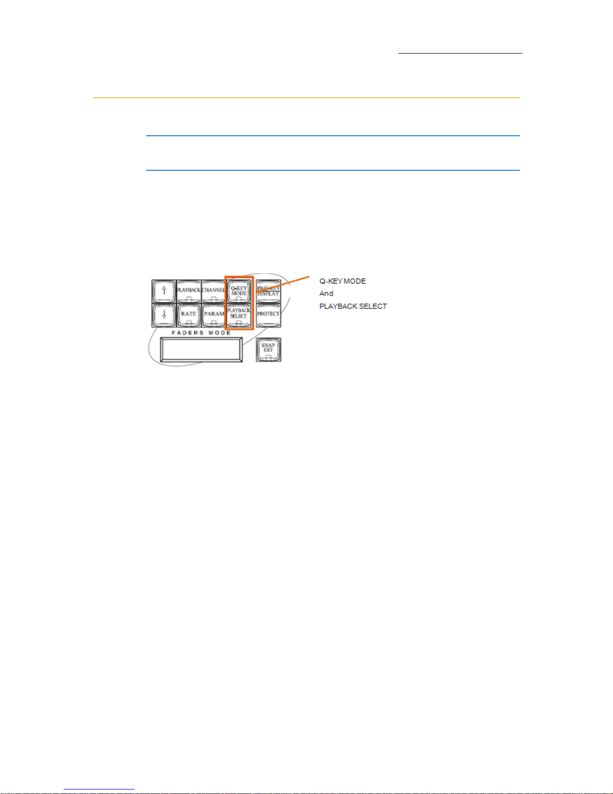
91
VECTOR
PLAYBACK
Vector Violet Playback and Q-Key functionality
IMPORTANT! This section applies only to Vector Violet and Ultra Violet
consoles.
The Vector Violet and Ultra Violet do not have their own physical QKeys, instead they have a “Q-Key” mode key that can simulate 20 QKeys. This gives the ability to change the functions of the PB Select key
to the Q-Key control key. Once the System is in Q-Key mode you have
have access to 20 PB’s and 20 Q-Keys per page.
The Vector Violet has 2 additional keys:
Figure 26: Q-KEY MODE and PLAYBACK SELECT keys
Q-KEY MODE is a toggle to switch the Playback keys to function as
either PB or QKeys. When the
Q-KEY MODE is ON the LED is Red and
the Command line displays
[Q-Key].
PLAYBACK SELECT when pressed enables all PB keys to become the
Select keys.
The Q-Key Mode key
When Q-KEY MODE is ON:
When the Q-KEY MODE is ON the LED is Red and the Command line
displays
[Q-Key].
There will be 20 PB's and 20 Q-Keys available per page and the
SELECT keys of the PB's will become the Q-Keys control key.The
Sequences for using the PB's and Q-Keys are slightly different as
there are NO select keys for the PB's and Q-Keys.
When
Q-KEY MODE is OFF:
There will be 20 PB's per page with NO access to the Q-Keys and the
operations are the same as on all the other Vector Consoles.
Page 98
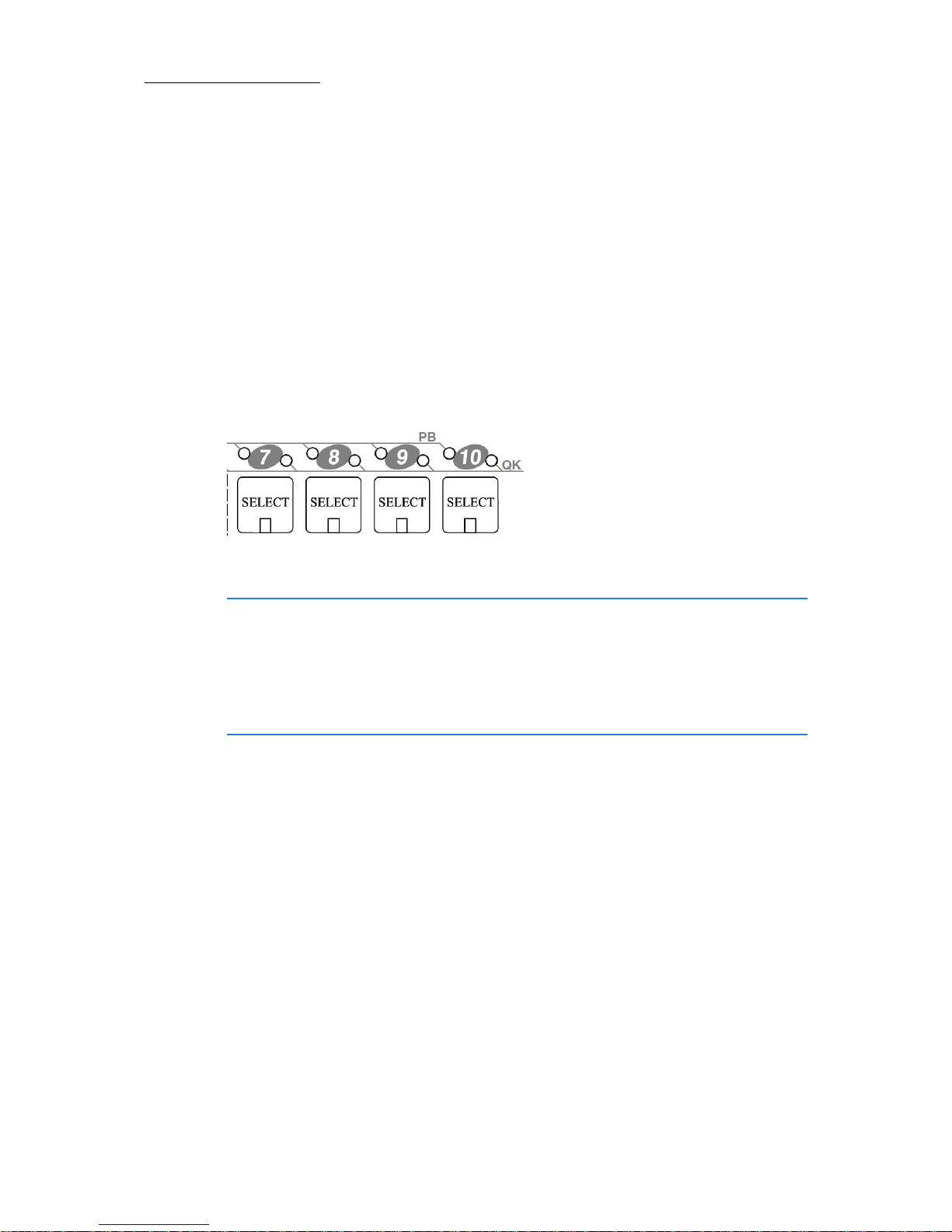
92
Compulite
Chapter 5
The Playback Select key
PLAYBACK SELECT key has a green LED that turns on whenever the key is
pressed. e.g
STORE, PLAYBACK SELECT, (LED turns green), SELECT for
Playback # (After the assignment -the LED turns off).
The Playback/Q-Key LEDS
Each Playback/QKEY has 2 LEDS indicating whether this control is
assigned. The Left LED is for Playback assignment and right LED is for
QKey assignment. The color of these 2 LEDS is the same as in all
Vectors models. (green for QList, orange for Temporary cue, red for
Chaser).
Figure 27: Each PB/Qkey has 2 LEDS
IMPORTANT! When a show is loaded from a Vector with Qkeys
assigned, the Qkey assignments will be loaded to the virtual Qkeys. The
right (Q-Key) LED of the PB will be ON according to the assigned object
(Qlist, Chaser or temporary cue) which helps you see what assignments
are on the Qkeys. Pressing the Qkey Mode key will give you physical
access to the Qkeys.
To assign QLIST 2 to Q-Key 19
Q-KEY-MODE is on (red LED is on).
1. Press
QLIST, select number 2.
2. Press
PLAYBACK SELECT.
3. Press Select for a Qkey device 19.
Qkey 19 LED (above the SELECT key) is lit green.
Page 99

93
VECTOR
PLAYBACK
To free QKEY 19
1. Press Q-KEY-MODE.
2. Press FREE.
3. Press PLAYBACK SELECT.
4. Press Select for a QKEY device 19.
QKey 19 led (above the SELECT key) is turned off.
To play QKEY 19
1. Press Q-KEY-MODE.
2. Press [Top Key] (below the SELECT key).
Tip! All playback control keys (such as FREE, SOLO, PAUSE etc) operate
in similar sequence order in QKey mode. Please look at sequences for
PB RELEASE to operate any one of them.
Page 100
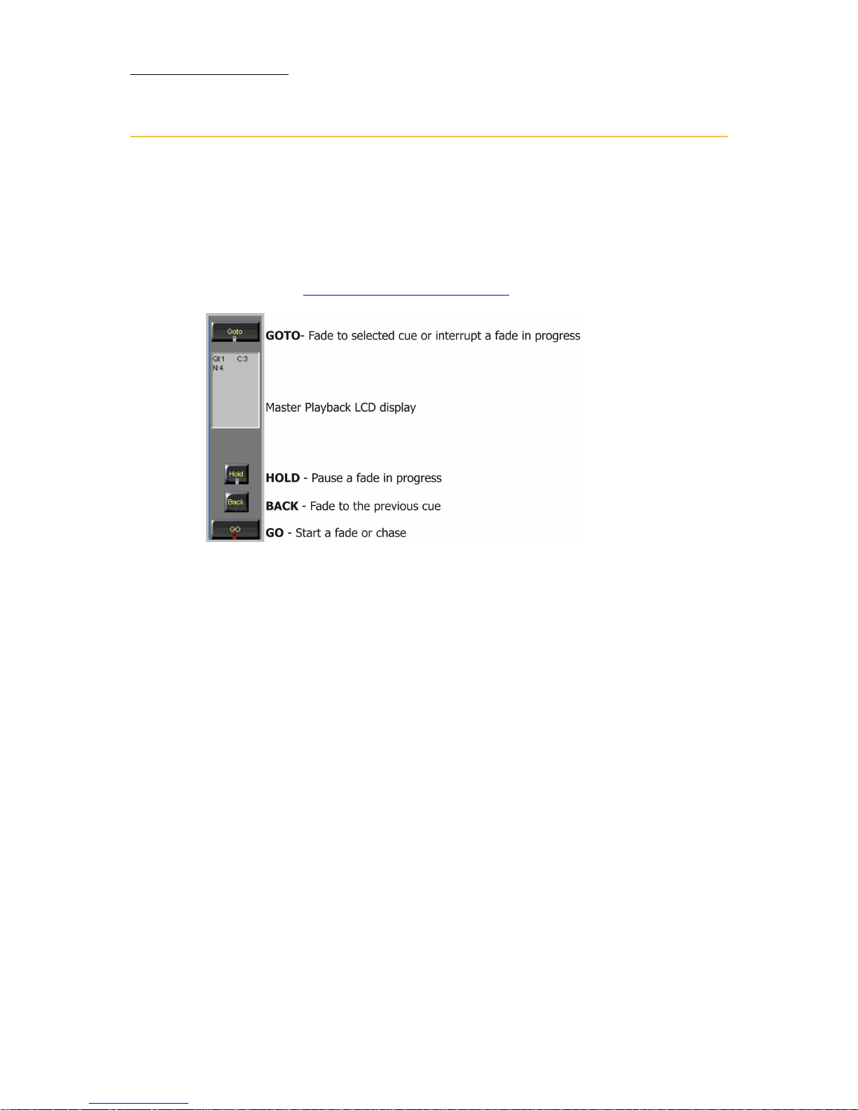
94
Compulite
Chapter 5
Master Playback
AB is the default master playback, but any playback device can be used
as the master playback. When a playback device is acting as the master
playback its
SELECT key’s LED is on.
There are dedicated control keys and an LCD display for the master
playback device. The Qlist resident on the master playback is the
default Qlist. “
Multiple QLists” on page 77.
Figure 28: Master playback LCD and control keys
To designate the master playback device
Press SELECT twice; the key's LED is lit.
Running a QList on the master playback
The master playback has a set of dedicated controls and an LCD display
that shows the current and next cue.
To fade to the next cue
Press GO.
To fade to the previous cue
Press BACK.
To pause the fade
Press HOLD.
 Loading...