

Page 1

User’s Guide
for
Compulite R & D Version 4.1
May 1999
Page 2

Table of Contents
Part 1 – General
Chapter 1 Introduction ......................................................................................................... 1-1
Using this User’s Guide....................................................................................................1-3
Setting up Spark..........................................................................................................1-3
New users ...................................................................................................................1-3
Common Terms................................................................................................................1-3
Editing terms............................................................................................................... 1-3
Playback terms............................................................................................................1-4
Text conventions...............................................................................................................1-4
Chapter 2 General Operation................................................................................................2-1
The Editor Section............................................................................................................2-2
F keys .........................................................................................................................2-3
Programming memories...............................................................................................2-3
Editor color key...........................................................................................................2-3
Editor error trapping....................................................................................................2-4
Clearing the ed itor.......................................................................................................2-4
Parameter Control.............................................................................................................2-4
The wheels..................................................................................................................2-4
A/B Crossfader.................................................................................................................2-5
Controllers........................................................................................................................ 2-7
Soft Keys..........................................................................................................................2-8
Assigning the default mode..........................................................................................2-8
Assigning a temporary mode........................................................................................2-8
Using the Soft Keys for playback control.....................................................................2-9
Color code for Soft Key LEDs.....................................................................................2-9
General Master ...............................................................................................................2-10
Menus............................................................................................................................ 2-10
Acce s sing menus.......................................................................................................2-10
Exiting the menu mode..............................................................................................2-12
Text & the Alphanumeric Keyboard ................................................................................2-12
A page of text............................................................................................................2-12
Erasin g text...............................................................................................................2-13
Using the text keyboard for programming..................................................................2-13
Getting Help...................................................................................................................2-14
System Status.................................................................................................................2-14
Chapter 3 Displays...............................................................................................................3-1
Display Control ................................................................................................................3-2
Display Formats................................................................................................................ 3-2
Selecting display formats.............................................................................................3-3
Customizing the display format...................................................................................3-3
The Stage Display.............................................................................................................3-4
Channels.....................................................................................................................3-4
Spots...........................................................................................................................3-4
The Playback Display .......................................................................................................3-5
Messages and Commands .................................................................................................3-5
Output Color Key..............................................................................................................3-6
The X-Fade Exam Display................................................................................................ 3-6
Exam Displays..................................................................................................................3-7
Chapter 4 Quick Start...........................................................................................................4-1
Setting Up Spark............................................................................................................... 4-2
Page 3

i
i
Configuring Spark............................................................................................................4-2
Patching...........................................................................................................................4-2
Patching dimmers to channels ..................................................................................... 4-3
Patching scrollers to channels...................................................................................... 4-3
Patching and addressing moving lights........................................................................ 4-3
Creating homogeneous beam movement ...................................................................... 4-4
Selecting Channels & Spots.............................................................................................. 4-4
Selecting channels & assigning intensity......................................................................4-4
Selecting scrollers & assigning frames.........................................................................4-4
Selecting spots & assigning parameter values ..............................................................4-4
Programming Memories ...................................................................................................4-5
Playback Memories on A/B.............................................................................................. 4-5
Playback Chasers..............................................................................................................4-6
Recording a Show File...................................................................................................... 4-6
Part 2 - Basic Editing
Chapter 5 Selecting and Editing Channels & Scrollers.......................................................... 5-1
Selecting Channels........................................................................................................... 5-2
Changing the number default selection ........................................................................ 5-2
Selecting a single channel............................................................................................5-2
Selecting multiple nonsequential channels...................................................................5-3
Selecting a range of channels.......................................................................................5-3
Reselecting the last channel selection .......................................................................... 5-3
Grabbing channels in the editor and on stage............................................................... 5-4
Assigning Int ensity Levels................................................................................................ 5-4
Dimmer level assignments using @............................................................................. 5-4
Repeating an intensity assignment...............................................................................5-5
Releasing a Channel from t he Editor.................................................................................5-5
Selecting and Editing Scrollers .........................................................................................5-6
Color code for scroller channels.................................................................................. 5-6
Assigning frame values .............................................................................................. 5-7
Releasing a scroller from a memory.............................................................................5-7
Chapter 6 Selecting and Editing Spots.................................................................................. 6-1
Igniting Spots...................................................................................................................6-2
Igniting DMX spots.....................................................................................................6-2
Igniting S-Mix, L-Mix, and High End protocol spots....................................................6-3
Ignition exam.............................................................................................................. 6-4
Selecting Spots.................................................................................................................6-4
Changing the number default selection ........................................................................ 6-4
Selecting a single spot.................................................................................................6-5
Selecting multiple spots...............................................................................................6-5
Recalling the last spot selection................................................................................... 6-5
Selecting spots in the editor and on stage.....................................................................6-6
Spot display control.....................................................................................................6-6
Mix Editing of Spots.........................................................................................................6-6
Spot Parameters................................................................................................................ 6-7
Parameter wheels........................................................................................................ 6-7
Types of parameters .................................................................................................... 6-7
Selecting parameters and assigning values................................................................... 6-7
Returning to home values .......................................................................................... 6-13
Copying parameter values......................................................................................... 6-13
Releasing Spots/Parameters............................................................................................6-15
Releasing a spot from the editor................................................................................. 6-15
Releasing a parameter from the editor........................................................................ 6-15
Page 4

iii
Chapter 7 Programming Memories.......................................................................................7-1
Programming Memories....................................................................................................7-2
Displays............................................................................................................................7-3
Programming with Channels.............................................................................................7-3
Programming with Scrollers ..............................................................................................7-4
Programming with Spots...................................................................................................7-5
Storing spot parameters from tracking..........................................................................7-6
Using the Copy Function...................................................................................................7-6
Copying channel intensities from the editor..................................................................7-6
Copying channel intensities from a memory.................................................................7-7
Copying scroller frames from the editor.......................................................................7-7
Copying scroller frames from a memory......................................................................7-7
Copying all spot parameters from the editor .................................................................7-8
Copying selected spot parameters from the editor.........................................................7-8
Copying spot parameters from a memory.....................................................................7-8
Copying selected parameters from a memory...............................................................7-9
Programming a Blackout Cue............................................................................................7-9
Sequential Memory Programming...................................................................................7-10
Using the Call Function ..................................................................................................7-11
Using Call to store the current lighting state............................................................... 7-11
Using Call and controller assignments.......................................................................7-12
Merging selected output sources ................................................................................7-13
Editing after Call.......................................................................................................7-13
Calling A/B...............................................................................................................7-14
Call and the General Master.......................................................................................7-14
Examining Memories, Channels, & Spots........................................................................7-16
Examining memories.................................................................................................7-16
Examining channels.................................................................................................. 7-17
Examining spots ........................................................................................................7-18
Text for Memories..........................................................................................................7-19
Programming in Blind Mode...........................................................................................7-20
Resetting the blind editor...........................................................................................7-20
Fade Times .....................................................................................................................7-21
Assigning fade times whil e pr ogramming memories................................................... 7-22
Assigning fade tim es t o a range of memor i es .............................................................7-22
Assigning fade times t o non-sequential memories ......................................................7-23
Modi f ying time ass ignments......................................................................................7-23
Converting Memories to Editor Groups...........................................................................7-24
Converting a memory whe n t he e d itor is emp ty..........................................................7-24
Converting a memory to a group when the editor is active.......................................... 7-25
Inse rt ing a Memo ry.........................................................................................................7-26
Memory Operations in the Editor....................................................................................7-26
Renami n g and exch anging me mories.........................................................................7-26
Copying memories ...................................................................................................7-27
Erasin g memorie s......................................................................................................7-28
The Memory Operations menu........................................................................................7-29
Renami n g memorie s..................................................................................................7-29
Copying a memory....................................................................................................7-30
Dele tin g memorie s....................................................................................................7-30
Mask.............................................................................................................................. 7-31
Selecting a mask........................................................................................................7-31
Selecting a range of masks.........................................................................................7-31
Assigning a mask to a control l er ................................................................................7-32
Selecting channels/spots from assignment..................................................................7-32
Programming with Libraries............................................................................................7-32
Chapter 8 Loops & Links.....................................................................................................8-1
Loops ...............................................................................................................................8-2
Page 5

i
v
Programming an automatic continuous loop................................................................. 8-2
Programming a manual continuous loop ......................................................................8-3
Programming a manual Loop.......................................................................................8-3
Programming a f i n ite loop........................................................................................... 8-3
Programming an autofollow loop ................................................................................. 8-4
Programming a follow-on cue......................................................................................8-4
Erasin g loop assi gnments............................................................................................ 8-5
Erasing an autofollow loop assignment ........................................................................ 8-5
Link................................................................................................................................. 8-6
Programming a link between two memories.................................................................8-6
Programming a link among a group of memories.........................................................8-6
Erasin g a link assignment............................................................................................ 8-6
Viewing links..............................................................................................................8-7
Chapter 9 Modifying Memories ...........................................................................................9-1
Basic Memory Modification ............................................................................................. 9-2
Using STORE STORE......................................................................................................9-3
STORE STORE modes............................................................................................... 9-3
Storing to the first active playback device....................................................................9-4
Storing to the all playback devices............................................................................... 9-4
Storing to selected playback devices............................................................................ 9-5
Using Delta...................................................................................................................... 9-5
Programming a delta via memory modification............................................................ 9-6
Replacing a delta with a new delta...............................................................................9-6
Programming a delta in the ed itor................................................................................9-7
Programming a delta via store store............................................................................9-7
Examining delta.......................................................................................................... 9-7
Applying delta ............................................................................................................9-8
Testing the delta........................................................................................................ 9-11
Erasing delta ............................................................................................................. 9-11
Modi f ying delta ........................................................................................................9-11
Using Memory Range Modification................................................................................ 9-12
Modifying a channel over a range of memories.......................................................... 9-12
Adding a new channel to a range of memories...........................................................9-12
Releasing channels from a range of memories............................................................ 9-13
Releasing scrollers from a range of memories............................................................ 9-13
Releasing Channels, Spots, Scrollers from Memories...................................................... 9-14
Releasing spots .........................................................................................................9-14
Releasing channels.................................................................................................... 9-14
Releasing scrollers.................................................................................................... 9-14
Part 3 - File Management and Printing
Chapter 10 Data Storage, Retrieval, & Printing...................................................................10-1
Recording Show Files ..................................................................................................... 10-2
Loading show files.......................................................................................................... 10-3
Load options.............................................................................................................10-3
Warning Difference...................................................................................................10-4
Deleting Show Files........................................................................................................10-5
Printing .......................................................................................................................... 10-6
Printing options......................................................................................................... 10-6
Using Print Screen.................................................................................................... 10-6
Programming a print command macro....................................................................... 10-7
Page 6

v
Part 4 - Playback
Chapter 11 The Crossfader.................................................................................................11-1
Overview........................................................................................................................11-2
Displays....................................................................................................................11-2
Assigning to the Crossfaders ...........................................................................................11-3
Assigning memori es .................................................................................................. 11-3
Assigning edit or groups.............................................................................................11-4
Freeing assig n ments........................................................................................................11-4
Sequencing Memories .....................................................................................................11-5
The Playback Keys .........................................................................................................11-6
Automatic Go............................................................................................................ 11-6
Exiting a continuous automatic or manual loop..........................................................11-7
Modifying the Fade Rate.................................................................................................11-7
Moving the crossfaders manually...............................................................................11-7
Using the Rate Wheel................................................................................................11-7
Split crossfad ers and moving lights .................................................................................11-8
Chapter 12 Controllers and Chasers....................................................................................12-1
Overview........................................................................................................................12-2
Displays....................................................................................................................12-2
Assign mode .............................................................................................................12-4
Controller LEDs........................................................................................................12-4
Control priority for spots...........................................................................................12-4
Assigning Memori es .......................................................................................................12-4
Assigning a range of memories t o sequent ia l controllers.............................................12-5
Assigning an unsp ecifi ed ran g e of memor i es to sequen ti al con trollers .......................12-5
Assigning masks........................................................................................................12-5
Assigning Edit or Groups.................................................................................................12-6
Assigning chann el s....................................................................................................12-6
Assigning spots .........................................................................................................12-8
Assigning Scroll ers ......................................................................................................... 12-9
Adding text to a grp assignment.................................................................................12-9
Examining a Controll er Assi gnm ent.............................................................................. 12-10
Freeing a Controller Assignment...................................................................................12-10
Freeing multiple controller assignments ................................................................... 12-11
Freeing all controller assignments............................................................................12-11
Using ‘Go Controller’...................................................................................................12-12
Fade times with ‘Go Controller’ ..............................................................................12-12
Chasers......................................................................................................................... 12-13
Chaser displays........................................................................................................ 12-13
Assigning chasers to controllers ............................................................................. 12-15
Playing back chasers................................................................................................12-16
Modi f ying the c haser rate........................................................................................12-17
Assigning Controll ers as Submasters.............................................................................12-19
Assigning controllers as inhibit submasters ..............................................................12-19
Submastering p layback devic es................................................................................12-19
Sound- t o-Lig ht............................................................................................................. 12-21
Turning on sound-to-light........................................................................................12-21
Turning off Sound-to-Light ....................................................................................12-22
Sound-to-Light display............................................................................................12-22
Controller resp onse..................................................................................................12-22
Chapter 13 Control Priority................................................................................................13-1
Playback Control Priority................................................................................................13-2
LTP Playback Mode........................................................................................................13-3
Actions that change the control priority stack............................................................. 13-3
Page 7

v
i
Enabling LTP control mode.......................................................................................13-3
Disabling LTP control mode...................................................................................... 13-4
Viewing the co ntrol prio r ity.......................................................................................13-4
Part 5 - Advanced Topics
Chapter 14 Libraries .......................................................................................................... 14-1
Overview........................................................................................................................14-2
Color code for Libraries............................................................................................ 14-2
Programming a Library...................................................................................................14-3
Text for Libraries............................................................................................................14-3
Examining Libraries.......................................................................................................14-4
Viewing the library list.............................................................................................. 14-4
Examining a selected library......................................................................................14-4
Viewing library assignments in memories.................................................................. 14-4
Programming Memories with Libraries...........................................................................14-5
Copying from a Library.................................................................................................. 14-5
Editing Libraries............................................................................................................. 14-6
Modi f ying a libra ry...................................................................................................14-6
Adding spots to a library........................................................................................... 14-6
Remo ving spots f rom a libra ry..................................................................................14-7
Updating a library using STORE STORE.................................................................. 14-7
Erasin g a Li brary............................................................................................................ 14-8
Programming a Delta with Libraries................................................................................14-8
Chapter 15 Part Qs.............................................................................................................15-1
Overview........................................................................................................................15-2
Part Qs display ...............................................................................................................15-2
Programming Memories with Parts ................................................................................. 15-3
Programming Parts with channels..............................................................................15-3
Programming Parts with scrollers..............................................................................15-4
Programming Parts with spots................................................................................... 15-4
Programming Parts with selected parameters............................................................. 15-5
Dividing a Memory into Parts.........................................................................................15-5
Adding a Part to a Memory............................................................................................. 15-6
Modi f ying a Part.............................................................................................................15-6
Removing channels/spots from a Part........................................................................ 15-7
Removing Part assignments.......................................................................................15-7
Modi f ying time ass ignments......................................................................................15-8
Using Parts as Editor Groups..........................................................................................15-8
Assigning Part s to Controllers......................................................................................... 15-8
Playing Back Parts..........................................................................................................15-8
Chapter 16 Events..............................................................................................................16-1
Overview........................................................................................................................16-2
The Event Menu............................................................................................................. 16-2
Programming an event...............................................................................................16-3
Adding operations to an Event................................................................................... 16-3
Dele tin g an event...................................................................................................... 16-4
Adding text to an event .............................................................................................16-4
Examining Events..................................................................................................... 16-5
Opera ting Events............................................................................................................ 16-5
Assigning an Event to a memory ............................................................................... 16-5
Erasing an event from a memory............................................................................... 16-6
Operating an event using the editor............................................................................16-6
Chapter 17 Snaps............................................................................................................... 17-1
Overview........................................................................................................................17-2
Programming a Snap ...................................................................................................... 17-2
Page 8

vii
Adding Text to Snaps......................................................................................................17-3
Examining Snaps............................................................................................................17-3
Viewing the snap list.................................................................................................17-3
Examining a selected Snap........................................................................................17-3
Erasing Snaps.................................................................................................................17-4
Operating Snaps..............................................................................................................17-6
Operating Snaps in non-forcing mode........................................................................17-6
Operating Snaps in forcing mode...............................................................................17-7
Using S n ap to clear al l assignme n t s........................................................................... 17-7
Chapter 18 Macros.............................................................................................................18-1
Overview........................................................................................................................18-2
The Macro Menu............................................................................................................18-2
Programming Macros................................................................................................ 18-3
Modifying Macros.....................................................................................................18-4
Linking Macros.........................................................................................................18-4
Dedicated function Macros........................................................................................18-5
Adding text to Macros...............................................................................................18-6
Deleting Macros........................................................................................................18-7
Last 40 keypresses.....................................................................................................18-7
Using Teach Macro.........................................................................................................18-8
Programming with Teach Macro................................................................................18-9
Operating Macros...........................................................................................................18-9
Operating Macros Using Soft Keys ............................................................................18-9
Operating Macros using the numeric keypad............................................................18-10
Part 6 - System Configuration and Patching
Chapter 19 System Configuration.......................................................................................19-1
Accessing Service Tools.................................................................................................19-2
Configuring in Service Tools...........................................................................................19-2
Passcode.................................................................................................................... 19-3
Navig ating in t he C onfig System................................................................................19-3
System Type..............................................................................................................19-3
CRT number .............................................................................................................19-3
Configuring control capacity...................................................................................... 19-3
Special functions.......................................................................................................19-4
Special Numbers ....................................................................................................... 19-6
System Parameters..........................................................................................................19-7
Operator definable parameters...................................................................................19-7
Print menu screen......................................................................................................19-8
Chapter 20 Channel and Scroller Patching..........................................................................20-1
The Channel Patch..........................................................................................................20-2
Patching dimmers to channels....................................................................................20-3
Patching dimmers to scrollers....................................................................................20-3
Patching channels to dimmers...................................................................................20-4
Clearing patch assignments........................................................................................20-5
Restoring the default patch ........................................................................................20-6
Proportional patching ................................................................................................20-6
Exchanging dimmers.................................................................................................20-7
Assigning dimm er curves .......................................................................................... 20-7
Disabling General Master control...............................................................................20-9
Enabling General master control..............................................................................20-10
Examining soft patch assignments...........................................................................20-10
Viewing free dimmers............................................................................................. 20-11
The Scroller Patch.........................................................................................................20-12
Selecting a scroller ..................................................................................................20-13
Page 9

vii
i
Patching scrollers to control channels...................................................................... 20-13
Patching DMX addresses to scrollers ....................................................................... 20-14
Defining a dark gel frame........................................................................................ 20-14
Changing the number of frames............................................................................... 20-15
Setting up frames.................................................................................................... 20-15
Copying the scroller setup.......................................................................................20-16
Chapter 21 Spot Management and Patching........................................................................ 21-1
The Mix Output Menu.................................................................................................... 21-2
Mix Output menu display.......................................................................................... 21-2
Patching spot numbers...............................................................................................21-4
Assigning output a ddresses........................................................................................21-4
Def i ni ng d evices ....................................................................................................... 21-8
Editing parameter wheels assignments..................................................................... 21-12
Defining an external dimmer................................................................................... 21-13
Creating a device library.......................................................................................... 21-16
The Spot Patch ............................................................................................................. 21-17
Assigning patch position ......................................................................................... 21-17
Returning to the default position .............................................................................. 21-18
Part 7- Communication Protocols
Chapter 22 MIDI in/out......................................................................................................22-1
Configuring the System for MIDI................................................................................... 22-2
Configuring for MIDI in Service Tools......................................................................22-2
Defining the MIDI channel in System Parameters......................................................22-2
Enabling/Disabling MIDI ...............................................................................................22-3
Turning MIDI on ...................................................................................................... 22-3
Turning MIDI off...................................................................................................... 22-3
The MIDI Menu.............................................................................................................22-3
Enabling and disabling keys and controllers...............................................................22-4
Editing MIDI data for keys and controllers................................................................ 22-5
MIDI Macro ................................................................................................................... 22-6
MIDI Sync.....................................................................................................................22-6
Setting up MIDI Sync in the master console...............................................................22-7
Setting up MIDI sync in the slave console..................................................................22-7
Enabling/disabling MIDI Sync.................................................................................. 22-7
Standard MIDI codes......................................................................................................22-8
Chapter 23 SMPTE............................................................................................................23-1
Configurin g the system for SMPTE ................................................................................23-2
Configuring the SMPTE/DMX Input connector......................................................... 23-2
Configuring the number of frames............................................................................. 23-3
Teaching SMPTE Time .................................................................................................. 23-3
Starting at a selected Event........................................................................................ 23-4
Exiting the teach function..........................................................................................23-4
Manual assignment and editing the SMPTE code ............................................................23-5
Erasing a SMPTE time code...................................................................................... 23-5
Playback with SMPTE....................................................................................................23-6
Exiting SMPTE playback .......................................................................................... 23-6
Chapter 24 DMX Input ...................................................................................................... 24-1
Configuring Spark for DMX Input.................................................................................. 24-2
The DMX Input patch..................................................................................................... 24-3
Patching input channels.............................................................................................24-3
Clearing Input patch assignments ..............................................................................24-4
Returning to the default patch.................................................................................... 24-4
Examining DMX input assignments ..........................................................................24-5
Assigning macr os to DMX input ............................................................................... 24-5
Page 10

i
x
Canceling a Macro assignment ..................................................................................24-6
DMX Input and patch 999...............................................................................................24-6
Ignoring Patch 999....................................................................................................24-6
Using DMX Input under Patch 999............................................................................24-6
Part 8 - Appendices
Appendix A Service Tools...................................................................................................A-1
Accessing Service Tools.................................................................................................. A-2
Main Menu ...................................................................................................................... A-2
Diagnostics......................................................................................................................A-3
Upgrading Software.........................................................................................................A-4
Using the Software Upgrade option ............................................................................A-4
Upgrading software under Disk Operations................................................................. A-5
Disk Operations...............................................................................................................A-6
Forma tting disk s.........................................................................................................A-6
Recording the system configuration............................................................................A-6
Loading the system configuration............................................................................... A-7
Appendix B Patch 999......................................................................................................... B-1
Patch 999......................................................................................................................... B-2
Configuring for Patch 999.......................................................................................... B-2
Programming and burning Patch 999.......................................................................... B-3
Editing the file on a PC............................................................................................... B-4
Color key for Patch 999.............................................................................................. B-5
Examining Patch 999..................................................................................................B-5
Page 11

CHAPTER 1
INTRODUCTION
This User’s Guide contains 24 chapters and 2 appendices. The User’s Guide is divided
into 8 parts.
Part 1 - General
•
Chapter 1 Intr oduction
•
Chapter 2 General Operation
A concise overview of operational features, such as the Editor, Playback Devices, Soft
Keys, Display Formats, and On Line Help.
•
Chapter 3 Di spl a ys
Descriptions of the different displays available in Spark and operating instructions for
Display control.
•
Chapter 4 Quick Start
This chapter provides operating instructions for the most basic functions on Spark. Its
purpose is to provide quick instruction to operators familiar with lighting consoles.
Part 2 – Basic Programming
•
Chapter 5 Selecting and Editing Channels and Scrollers
Operating instructions for basic channel and scroller selection, advanced selection
sequences, and assigning dimmer and frame values.
•
Chapter 6 Selecting and Editing Spots
Operating instructions for basic moving light (spot) selection, advanced selection
sequences, spot parameter selection, and assigning parameter values.
•
Chapter 7 Programming Memories
Basic programming functions, including using the Call function, how to convert
memories to editor groups, assigning Fade Times, programming in Blind mode, and
inserting memories.
•
Chapter 8 Loops & Links
Programming memories with Loops to run as Chasers on the controllers or on the
crossfader. Linking non-sequential memories.
•
Chapter 9 Memory Modification
Operating instructions for basic memory modification, quick modification for
memories assigned to playback devices using the STORE STORE function, and Delta
tracking modification.
Part 3 – File Management and Printing
•
Chapter 10 Data Storage, Retrieval, & Printing
How to Record and Load show files, and Printing options.
Part 4 - Playback
•
Chapter 11 T he A/ B Crossfader
Making assignments to the A/B crossfader, playback using automatic Go commands
or manual operation, and automatic Rate control.
•
Chapter 12 Controllers
Assigni ng memories, g roups, and C hasers to th e C on t rollers. Usin g t he automatic Go
and manual playback operations. Rate control for Chasers.
Page 12

Using this User’s G uide
Spark
1-2
• Chapter 13 Control Priority
A description of Spark’s default control and using LTP.
Part 5 – Advanced Topics
• Chapter 14 Libraries
Operating instructions for programming, modifying, and using Libraries.
• Channel 15 Par t Qs
Programming memories with parts. Each Part can have unique delay and fade times.
• Channel 16 Event
Program events to operate multiple assignment and playback commands. Events can
be operated when assigned to memories sequencing on the A/B crossfader, in the
editor, or using SMPTE.
• Chapter 17 Sna p
Store ‘snapshots’ of all playback device assignments and their fade status. Snaps are
analogous to preset pages for Controllers. Spark supports 99 Snaps.
• Chapter 18 Macros
Spark supports up to 999 Macros. Operating instructions for programming Macros
blind, in the Macro menu, or live using the Teach macro function.
Part 6 – System Configuration and Patching
• Chapter 19 Sy stem Configuration
General system Configuration in Service Tools and using operator definable system
parameters in the System Parameters menu.
• Chapter 20 Channel and Scroller Patching
The Channel Patch provides functions for soft patching dimmers and channels,
assigning dimmer curves, assigning proportional levels to dimmers, examining patch
assignments. The Scroller Patch provides easy functions for setting up frames,
assigning control channels to scrollers, and copying scroller set ups.
• Chapter 21 Spot M ana g e ment and Pat c hing
The Mix Output menu provides functions to patch moving light type to control
numbers, assign DMX outpu t addresses, defin e device pr ofiles.
Part 7- Communication Protocols
• Chapter 22 M IDI
Enable MIDI communication and edit MIDI codes in the MIDI menu. The MIDI
synch option allows a second lighting console to synchronize crossfade operations
with the main console.
• Chapter 23 SM PTE
Assign SMPT E time codes to Events using the live Teach function and enable Spark
for automatic operation using SMPTE transmission.
• Chapter 24 DM X Input
Patch DMX Input channels to operate local console chan nels or macr os.
Appendices
• Appendix A Service Tools
Operating instructions for disk formatting, the Hardware diagnostics tool, and
software upgrade functions in Service Tools.
• Appendix C Dimmer Status and Patch 999
A description of the Dimmer Status reports available when using CMX protocol with
Compulite Dimmers. Instructions for editing Patch 999, which allows logical channel
patching.
Page 13

Using this User’s G uide
Spark
1-3
Using this User’s Guide
Setting up Spark
If you are setting up the system for the first time, you may want to consult Chapter 19
System Configuration, Chapter 20 Channel Patching, and Chapter 21 Spot Management.
New users
If you are new to lighting consoles or are unfamiliar with Compulite consoles, familiarize
yourself with the information in chapters 2 – 12. These chapters provide you with general
information and give you the building blocks to create and modify memories (cues), and
play them back. Chapters 13 – 18 deal with more advanced functions.
Common Terms
Three major capabilities are basic to lighting consoles: editing, playback, and patching.
Editing is the ability to select channels, spots, and scrollers, assign intensity and parameter
values, and record the resulting stage picture as a memory or cue. All functions related to
the playback structure of the show, such as event assignments, snaps, loops, and links are
part of the editing functions.
Playback is the ability to replay all the show data that you have created while editing.
Playback can be manual and automatic.
Patching includes all of the patching functions, which instruct the system how to
communicate with conventional projectors, color scrollers, other DMX512 protocol
elements, and moving lights that are controlled by the lighting console.
Editing terms
• Channel - Th e contr ol channel for DMX512 devices, which are not moving devices.
These includ e conventi onal projectors, col or scroll ers, smoke machi nes, etc.
• Intensity - Dimmer intensity of channels and spots.
• Present or active (in the editor) - Channels and spots that are displayed in white.
Everything present/active in the editor is included when recording a memory.
• Selected (in the editor) - Channels and spots that are displayed in red and therefore can
be assigned intensity or scroller values.
• Memory - is analogous to cue. The group in the editor, comprising the lighting state
on-stage, is stored as a memory. Memories are then played back.
• Librari e s - Gobo, Color, and P os ition libraries form a database used when
programming memories.
• Spot number - The number by which moving lights are addressed.
• Parameters - The attributes of moving devices.
• Value - The numerical value assigned to a parameter or a dimmer.
• Store - Save the information in the editor.
• Erase - Delete selected data.
Page 14

Text convent ions
Spark
1-4
• Delta - A tool for memory modification.
• Modify - Change stored information and fade rates.
• Frame - Scroller frame.
Playback terms
• Go - Initiate an automatic crossfade, controller fade, or chaser run.
• Hold - Stop any fade or chaser in progress.
• Multifade - Initiate a fade to the next memory in sequence before the fade in progress
is complete.
• End Stop - When crossfaders or the controllers are at either 0% or 100%.
• Off the End Stop- When the crossfaders or the controllers are at more than 0% or less
than 100%.
• Rate - The rate at which channels and spots fade in or out during a crossfade. The rate
at which a chaser runs.
• Step - Manually moving from the current memory to the next memory of a chaser.
• Sequence - The numerical sequencing of the memories on the A/B or C/D crossfaders.
Text conventions
• Panel [KEYS] are in square brackets, all caps, and bold.
• Messages are in italics.
• # refers to a number entered on the numeric keypad.
• Command line refers to the sequence of keystrokes executed and displayed in the gray
line at the bottom of the display monitor. The keystrokes in the command line are
represented in italics.
• Prompt line refers to prompts occurring i n menus; th ese are italicized.
• Desk, console, and system are used interchangeably.
Page 15

CHAPTER 2
GENERAL OPERATION
The Editor Section
F keys
Programming memories
Editor color key
Editor error trapping
Clearing the edit or
Parameter Control
The wheels
A/B Crossfader
Controllers
Soft Keys
Assigni ng the default mode
Assigni ng a tempora ry mode
Using the Soft Keys for playback control
Color code for Soft Key LEDs
General Master
Menus
Accessing men u s
Exiting the menu mode
Text & the Alphanumeric Keyboard
A page of text
Erasing text
Using the text keyboard for programming
Locking/unlocking the keyboard
On-line Help
System Status
Page 16

The Editor Section
Spark
2-2
The Editor Section
Editing keys are used to:
• Select channels
• Select spots
• Assign i ntensity and p a rameter val u es
• Program memories
• Manipulate the display.
• Assign m emory attributes such as Loops, Links, and Part Qs.
Most keys are single purpose keys. Some keys however access two different functions. The
function in the lower half of the key is accessed using the [SHIFT] key.
The editors work in live or blind modes.
The numeric keypad is used for number selections. Some numeric selections may be done
on the Soft Keys.
Keystrokes appear in the yellow command line at the bottom of the display.
Spots and channels that are selected in the editor appear in red. Spots and channels that
appear in red are may be assigned parameter and intensity values.
Spots and channels that appear in white are present in the editor, but not currently
selected. They are included in any memory that is recorded.
The Editor operates in Live and the Blind modes. In Live mode any alterations made to
the stage picture are visible on stage. In Blind mode, memories are programmed or
modified without any interruption of the active stage picture.
Page 17

The Editor Section
Spark
2-3
F keys
The Function (F) keys are multi-purpose soft keys, generally used while working in
menus. When the system is not in menu mode, F1-F5 offer immediate access to macros 1-
5. F6 accesses all the rest of the macros. In menu mode these keys access the conveni ent
menu functions and options. These keys are also used for Delta application and editing
SMPTE time codes.
Programming memorie s
Memories are programmed by selecting channels and assigning intensity values or
selecting spots and assigning parameter values, then storing the resulting stage picture.
Each memory may be programmed for the following information:
• Fade in and out time, from 'cut' to 999.9 seconds.
• Delay, wait -in, and wait out time, from 'cut' to 999.9 seconds.
• An automatic follow-on memory created by using the loop function.
• Loops containing any number of memories.
• Links between non-sequential memories.
• Event assignments that automatically operate multiple functions
• Parts
• Text
Editor color key
Color Status
Red field Spots and channels selected in the editor. Spots and channels
displayed in red can be assigned intensity levels and parameter values.
White field Spots and channels that are present in the editor. When storing an
editor group as a memory the spots and channels displayed in white
and red are included in the memory.
Dark blue Spots and channels selected under memory modification (see Chapter
9 Modifying Memories).
Page 18

Parameter Contr ol
Spark
2-4
Editor error trapping
Spark has efficient error trapping, meaning that you cannot go too far wrong. An illegal
key press is immediately recognized. If you make a mistake the system displays messages
such as Ille gal Number or Invalid Sequence.
To get rid of this message and continue working, press the correct key. The correct
keystroke clears the error and allows the operation to continue.
Clearing the editor
You can clear the editor by pressin g either [RESET] or [CLEAR].
Using RESET
Press [RESET] once to fade out the channels and spots in the editor in Default Fade
Time. The Default Fade Time can be modified in the System Parameters menu. (See
Chapter 19 - System Configuration).
Press [RESET] twice to bump out the channels and spots in the editor.
Using CLEAR
[CLEAR] works as a regressive clear function.
Press [CLEAR] once- the command line clears, leaving only the selection mode (channel,
spot , or m emory).
Press [CLEAR] [CLEAR] - the output of selected channels and spots (displayed in red)
are cleared.
Press [CLEAR] [CLEAR] [CLEAR] - the selection mode is cleared from the command
line. The editor is now idle.
Parameter Control
Parameters are assigned values by either selecting a parameter on the Soft Keys in Param
mode and assigning a value using the numeric keypad or by using the wheels.
Using the wheels obviates selecting the parameter, as it is automatically selected when its
wheel is moved. When you select a parameter on the Soft Keys in param mode, the
appropriate wheel jumps to the wheel bank for the selected parameter.
[STEP UP] increments continuous parameters by bits and mixed or discrete step
parameters by steps.
[STEP DOWN] decrements continuous parameters by bits and mixed or discrete step
parameters by steps.
The wheels
The wheels operate in a 'non-collapsing' mode, meaning that the relative difference of the
values between different spots and channels is preserved when the spots and channels are
faded up or down.
Example: The editor contains spot or chann el 1 at 75% intensity and spot or chann el 2 at
85%. Select both of the spots (channels) an d begin to wheel up. Spot/channel 2 reaches
Page 19
A/B Crossf ader
Spark
2-5
full intensity when spot/channel 1 is at 90%. If you continue moving the wheel until
spot/channel 1 is at full and then you fade both spots/channels down, spot/channel 1 will
begin the fade first. The 10% difference in the spots'/channels' intensities is always
maintained.
Th e above example uses the dimmer parameter, however the explanation is valid for all
the parameters.
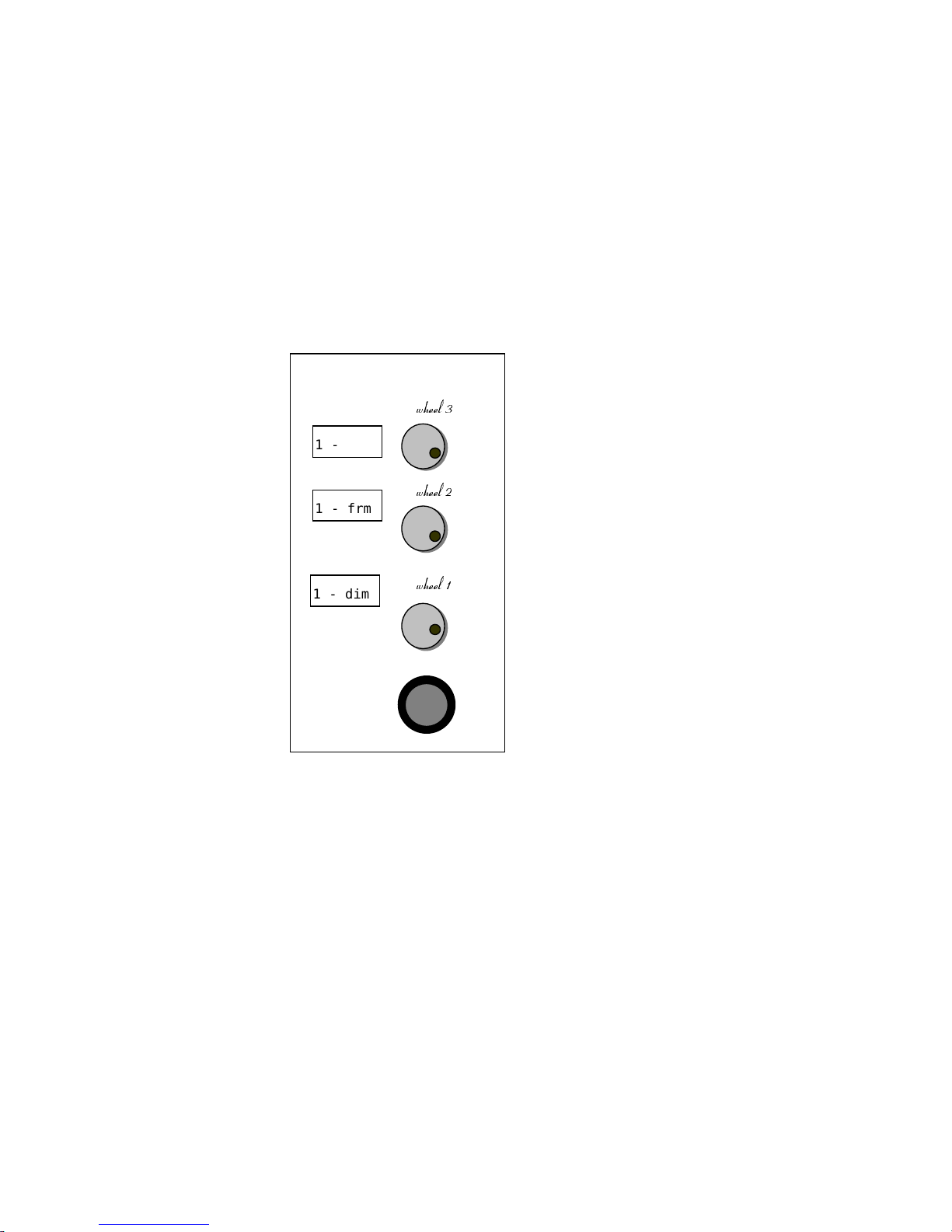
Spark’s control panel has three horizontal parameter wheels, numbered Wheel 1, Wheel 2,
and Wheel 3. When editing channels or when the editor is idle, the wheel assignments
are: Wheel 1 - int intensity, Wheel 2 - frm frame, Wheel 3 - rate chaser or A/B rate. For
editing spots the wheels are organized into 9 Wheel Banks. Parameters can be assigned to
more than one wheel.
To move from one parameter wheel bank to the next press [WHEEL+] or [WHEEL].
A/B Crossfader
The A/B crossfader is th e playback crossfader of th e s ystem .
Memories crossfade, sequencing in numerical order, when either an automatic Go
command is received or the crossfade is p erformed manually.
Fades are executed automatically (by pressing [GO]), accordin g to prerecorded fade rates,
or by manual movement of the crossfader. The crossfade rate can be overridden at any
point in the fade progression by using the rate wheel.
ZKHHO
ZKHHO
ZKHHO
1 - dim
1 - frm
1 - rt
Page 20
A/B Crossf ader
Spark
2-6
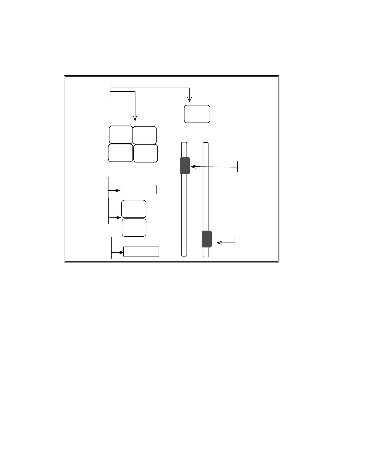
The A/B crossfader area of the console consists of: the A fader and the B fader, an LED
display for each fader that shows their current assignments, assignment keys and control
keys .
SEQ
AUTO
GO
TO
HOLD
GO
BACK
0
1
2
3
4
5
6
7
8
9
A
B
B
A
crossfade
control keys
LED display
for fader A
fader A
fader B
LED display
for fader B
10
9
8
7
6
5
4
3
2
1
A/B
Assignment
ke
y
s
Figure 1 The A/B crossfader area
The Playback area of the Stage display (display formats 1,3,5,7) provides information as to
the current status of the A/B crossfader.
The X-Fade Exam is a display dedicated to the A/B crossfader and is generally used
during pla yback. (see Chapter 3 – Displays)
The A/B crossfader supports Part Qs, memory loops, links, and Event assign m ent s.
Page 21
Controllers
Spark
2-7
Controllers
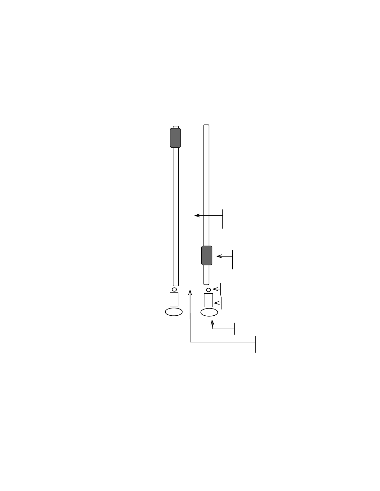
Spark has 20 controllers. Each controller has an associated Soft Key an d colored LED.
The controllers accept groups of ch annels and / or spots, memories, Cha ser, and effect
assignments. The controller position determines the output level of the controller
assignments.
Controllers can also be assigned to submaster the controller banks, the A/B crossfader, and
DMX Input or a s inhibit su bma st ers for channels/spots.
10
9
8
7
6
5
4
3
2
1
0
1
2
level
controller number
Soft Key
level scale
color coded LED
Controller handle
Figure 2 Controllers
In Assign mode the Soft Keys are used as assi gnments keys, to flash assignments, for
automatic fades, and for chaser control.
Colored LEDs provide information about the type of assignment and the fade status of the
Controllers/Soft Keys. Example: Controller 1 is assigned a chaser. The chaser is on hold
(not running). The LED under the controller blinks red. When the chaser is running the
LED is red and does not blink. If you are stepping through the chaser, the LED is orange.
Page 22

Soft Keys
Spark
2-8
Soft Keys
The Soft Keys have 4 modes.
Mode What the Mode does
Assign mode
Allows the assignment of groups of channels/spots, memories, or chasers
to controllers.
A fade function fades the controller assign m en t up a nd down.
The Soft Keys are also used for Go commands and to flash the
assignment.
10 simultaneous chaser assignments can be made. Chasers are assigned in
hard run mode or soft run mode and are easily switched from one mode to
the other. There is a special dedicated chaser display.
Controllers can be assigned as inhibitive submasters or can submaster the
upper bank of controllers, lower bank of controllers, A/ B, and DMX Input
channels.
Macro mode
Direct access to 40 M acros.
Snap mode
Direct access to 20 Snaps with 2 snap functions modes - non-forcing
(additive) and forcing (override)
Parameter mode
When ac tive (LE D on) the Soft Keys provide parameter selection
when spots are selected. This is enabl ed as default. This key can
be toggled to enable or disable.
Assigning the default mode
The Soft Key default mode is assigned by a double hit on
[ASSIGN], [SNAP],
or
[MACRO]
.
Assigning a temporary mode
You can temporarily change the Soft Key mode with a single hit on any of the mode keys.
The temporary mode is valid until the one of the Soft Keys is pressed; then the Soft Keys
return to the current default mode. Temporary modes are displayed on the LED display
preceded by an asterisk (*).
Example: The current default mode is assign. You want to go, temporarily, to macro mode
in order to operate macro 11. Press
[MACRO] (SK11
). The Soft Key mode returns to
Assign m ode.
Each mode has a secondary function that is accessed by pressing
[SHIFT]
.
Mode SHIFT function
Assign Fade memory or gr oup a ssi g nment from the controll er level to FL or
to 0.
Manual stepping for chaser assignment.
Macro Accesses macros 21 - 40.
Snap Operates Snap in forcing (override) mode.
Page 23

Soft Keys
Spark
2-9
Using the Soft Keys for playback control
In Assign mode the Soft Keys have 4 operational modes:
1. Flash mode is the default function for group and memory assignments. Pressing the
Soft Key bumps the controller assignment from its current level to full.
Chaser Go/Hold is the default for chaser assignments. Pressing the Soft Key starts the
chaser. Pressing it while a chaser is running stops and blacks out the chaser.
The [SHIFT] accesses the Go Controller operation, an automatic fade of the
controller assignment.
2. LATCH When active (LED on) the Soft Keys are on/off keys for memory and grp
assignments. Latch may be used in conjunction with either of the SOLO keys.
3. SOLO When this is active, pressing a SK blacks out the output from all of the
controllers except the selected one. May be used in conjunction with the latch
function.
4. – SOLO When this is active, pressing a SK blacks out the output of the selected
controller only. May be used in conjunction with the latch function.
Color code for Soft Key LEDs
Mode/Assignment Color Explanation
Macro mode Orange There is a recorded macro corresponding to the Soft
Key.
Snap mode Orange There is a recorded snap corresponding to the Soft
Key.
Assign m ode Green When there is a group, m em ory, or submaster
assignment present.
Chaser assignment Red blink
Red solid
Orange
Chaser on Hold
Chaser running
Step
It is possible to examine all controller assignments in the Assign, Ma cro, and Snap modes:
Press [EXAM] and the Soft Key.
In order to use the exam function the mode must be default mode and not a temporary
mode.
Page 24

General Master
Spark
2-10
General Master
The General Master controls the overall dimmer output of the console.
The General Master fader has a blackout key, which turns off all dimmer outputs in the
system. The GM blackout key can be disabled in the System Parameters menu.
The level of the General Master i s displa yed in the upper r i ght corner of the display. The
maximum level of the GM can be set to 100 or 200, in Service Tools/Config sys/F3.
Channels can be removed from General Master control. This is useful when using
scrollers a nd DMX devices such as smoke ma chines. (See Ch apter 27 Channel a nd
Scroller Management)
Menus
Menus provide tools for Patching, defining System Parameters, Memory Management,
Macros, and other special functions. The F (Function) keys are used to access th e options
and functions in each menu. Easy to follow prompts guide you through all menu functions.
Once you have opened the selected menu, you will notice that the functions of the F keys
change according to the type of task currently being addressed.
Accessing menus
Keypresses Results/Comments
1. Press [MENU] to view the menu
list.
2. Enter a menu by either pressing the
appropriate F k ey , displayed at the
bottom of the screen.
Or
Select t he number of the menu, as
it appears in t he numbered list and
press [ENTER]
Once in the sel ec ted menu, you will
notice that the functions of the soft (F)
keys change according t o the type of
task currentl y addr essed.
The prompt line asks all the relevant questions to guide you through the different tasks
and functions. .
If you make an error entering information while in a menu F6 Restart usually returns to
the beginning of the command chain. If you have made an error entering a number
selection, p ressing [CE] usually clears the error.
Number selections in the menu mode are entered on the numeric keypad of the console or,
in some cases, the alphanumeric keyboard. Text is typed on an alphanumeric keyboard.
Many of the different menus have more than 5 functions available. It is generally assumed
that if you do not see the function under discussion, you will page until you see the option.
To view the next page of functions press: F6 More Function
Page 25
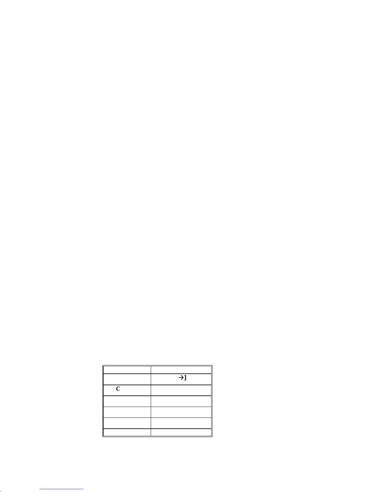
Menus
Spark
2-11
Spark contains the following menus:
Menu Purpose
1. Channel Patch Dimmer management includes soft patch, assigning dimmer
curves, defining proportional patch per dimmer, exchanging
dimmers, enabling or disabling General Master control. and testing
channels or dimmers. Patching for DMX input. Examin ing
patching for dimmers, channels, and scrollers.
2. Load Load show files from a floppy disk. All the data contained in a
show file can be loaded or selected parts, such as Libraries only
an d Macros only.
3. Memory Operations Rename, copy, delete memories, and clear the console’s memory.
5. Record Recording Spark’s memory contents to a floppy disk or to the hard
disk. File management.
7. Printer Generate hard copy of show data.
8. System Parameters General system information is displayed. There are options that
you can redefine to customize the system.
9. Macro Create, m odi fy, an d d elet e m a cros. Assign ma cros to DMX input
channels.
11. Test Test channels. Test dimmers regardless of their channel soft patch.
13. Spot Patch Create homogenous beam movement, for moving lights, regardless
of the physical orientation of the device.
14. Delete Play/Act Delete shows files from a floppy disk.
19. Mix Output Patch spot control numbers, assign output addresses, customize
device definitions, create a moving device definition library, and
load/record moving device definitions in device files. This menu
does not appear if the system is not configured for spots.
20. Scroll er Assign cont rol chan nels to scrollers, fine tune fr a m e set u p s,
enable the dark gel option. This menu does not appear if the
system is not configured for scrollers.
21. Event Program Events that trigger multiple playback events in the
system.
23. MIDI In/Out Enable keys and controllers for MIDI communication. Edit default
MIDI codes. Program macros of MIDI command strings. Enable or
disable th e MIDI Synch function.
Some of the F key functions may be carried out on the keypad as in editing:
F Key in menu KEYPAD
Thru
[
Æ
Æ
]
Channel
[CHANNEL]
Store
[STORE]
Memory
[MEMORY]
Next
[+]
Previous
[-]
Page 26

Text & the A lphanum er ic K ey boar d
Spark
2-12
Exiting the menu mode
Pressin g [RESET] exits the menu mode and resets the menu you have just exited. Press
once to return to menu list. The second press returns you to stage display.
[MENU] also exits the menu mode. Pressing this key exits the menu you are working on
without, in most cases, resetting the menu editor.
If for example, you are busy in the Spot Patch menu and you must temporarily exit the
menu, exit by pressing [MENU] returning to stage display. When you want to return to the
Spot Patch m enu, press [ME NU] to return to the point from which you exited the Spot
Patch menu and continue working.
You can exit the following menus without resetting the menu editor:
• Channel Patch
• Macro
• Spot Patch
• Mix Output
• Scroller Patch
Text & the Alphanumeric Keyboard
Text is typed on the alphanumeric keyboard.
You can add text to macros, memories, to show files when recording to the diskette, to
Snaps, Events, Libraries, controller group assignments, and even leave a note for the
second shift cr ew.
Operating instructions for adding text to the above ment ioned items are included in t he
sections dealing with those subjects.
A page of text
One page is available for text typed on the alphanumeric keyboard. This is useful for
recording any notes about special rigging, color changes during interval, cue synopsis, any
special comments pertaining to the show, etc.
If the blue text page contains text it is the first display to come up when the system is
turned on. This makes a convenient place to leave notes and messages for the next shift
crew.
To create a page of text:
Keypresses Results/Comments
1. Press [TEXT] [TEXT]
A blank blue screen is displayed. This i s the text page.
2. Type the text on the
alphanumeric keyboard
3. Press [STORE]
¾¾Note
If there is text on the Text p age, you can access the page by pressing Insert on the
alphanumeric keyboard.
Page 27

Text & the A lphanum er ic K ey boar d
Spark
2-13
Erasing text
The [ERASE] key is used to erase text.
Example: Delete the text from the Text page.
Keypresses Results/Comments
1. Press [TEXT]
2. Press [TEXT]
The blue Text page is displayed/
3. Press [ERASE]
Using the text keyboard for programming
The text keyboard can be used to program memories. .
The keyboard equivalents are:
a – Text q – Memory S – Status
b – Block r - Rem Dim* T – Delta
c – Channel s – Store @ - Intensity
d - Page Down t – Time ^ - Except
e – Effect u - Page Up 2* [ - +@*
f – Full v - (not used)
] -
@*
g – Mask w – Wait Bs – CE
h – Help x – Exa m spacebar – Clear
i - Teach Macro y - (not used) % - Flash
j - Move Fade* z – Zero & - +1 Store
k – Link A - Step Down
> - →
l - Loop B - Step Up Tab – Stage
m – Menu E – Event Del – Erase
n – Snap F – Frame Esc - Reset; During editing,
after inserting text to
memor ies, etc. use ESC to
exit text mode.
o – On P - Spot
p – Part R - Release
*Not Used for Spark.
Page 28

Getting Help
Spark
2-14
Locking/unlocking the keyboard
The alphanumeric keyboard has a lock to prevent unintentional editing. Activate the lock
by pressing Alt A. Unlock the keyboard for editing functions by pressing Alt A again.
This lock does not affect the functioning of the alphanumeric keyboard when [TEXT ] is
selected on the console.
¾
¾
Note
To use the Print Screen function on the text keyboard, you must first “unlock” the
keyboard.
Getting Help
On-line help contains a short description of each of the keys and the important key
sequen ces . When the hel p window is open, pres s i ng a key on t he console only displa ys its
help and does not execute its function.
Keypresses Results/Comments
1. Press [HELP]
A window opens in the middle of the
display screen.
2. Press any key you would lik e to know
more about.
A short expl anation and any relevant
keystroke sequences are displayed.
3. You can continue in Help by pressing
another key.
4. To exi t help, press [HELP] again.
¾
¾
Note
When the Help window is open t he console keys are disabl ed!
System Status
You can check the status of connected peripherals from Spark’s panel. The peripherals
include, the Macro Extension Keyboard, and the Remote Control Unit, and the
alphanumeric keyboard. You are notified if Spark’s battery is getting low.
Keypresses Results/Comments
1. Press [•] (dot).
The System S tatus window opens.
2. Press [STAGE] or [CLEAR] to return
to the edit or .
Page 29

CHAPTER 3
DISPLAYS
This chapter includes:
Display Control
Display Formats
Selecting display options
Customizing the display format
The Stage Display
Channels
Spots
The Playback Display
Messages and Command s
Output Color Key
The X-Fade Exam Display
Exam Displays
Page 30

Display Control
Spark
3-
2
All the parameters of the system ar e di splayed on a video d isplay monitor. There are 9
display formats to chose from.
The ar ea at the top of the scr een is reserved for messages, Bl ind mode flag , MI D I status,
and the G en er al Master level . The area at th e bot tom of the screen h ou ses the comman d
line, a clock, and the last stored memory or the last memory entered into the editor. The
comman d an d message area s ar e common to all of the display form ats.
When viewi ng the Stag e di splay, which sh ows t he active outp u t, a color code h elps you
differentiate bet we en the differ ent output sources for channels and spots .
Display Control
The following keys are used for display control:
Key What it do es
[STAGE] Access the Display Format options. Return to the Stage Display from most
Exam displays.
[PAGE UP] Go to the next page.
[PAGE DN] Go to the previous page. Access this key using [SHIFT].
[PAGE UP] Go to the next page of spots. This key shares space with ALL. Access this key
using [SHIFT].
[PARAM] When active (LED on) the Soft Keys operate as parameter selection keys
when spots are selected.
[MENU] Toggle the display between the Menu list and Stage mod e.
[+] Go to the next item. Example: Go from memory 2 exam to memory 3 exam.
[-] Go to the previous item. Example: Go from memory 3 exam to memory 2
exam.
Display Formats
0. Channel display only. The displ ay includes scroller fram es. The color of th e ch an nel or
scroller number displayed depends on the origin of the data, whether it derives from
the A/B crossfaders , a controller, the editor, or tracking.
1. Channel and playback. The playback display includes controller status and A/B status.
2. Spot di splay only. Th e appearance of the display depends on what size and how many
spots ap pear in the con figuration. Th e color of the sp ot n um ber displayed dep ends on
the origin of the data, whether it der i ves from A/B playba ck crossfader s, a controll er ,
the editor, or tracking.
3. Spots and playback. The playback display is identical to option 1.
4. Spots an d channels. The channels include scroller frames.
5. Chan nels, spots, a nd pla ybac k.
Page 31

Display Formats
Spark
3-
3
6. X-fade Exam shows the incoming and outgoing memories, a list of the next memories
in sequ ence, control ler/chas er status, chaser assignments, A/B fade rat e, and previous
memory on A/B.
7. X-fade and playback.
8. X-fade and spots.
In addition to the 9 main display options, the `Status Window' section of display formats
offers further display configurations.
Selecting display formats
When the s ystem is confi gured for spots and channels, there are up to 9 di splay options.
When the system is not configured for spots there are 4 display options available. The
display option framed in red is the current display.
Keypresses Results/Comments
1. Press [STAGE]
The display format opti ons are shown on the
CRT.
2. Enter the number of the di spl ay
you want on the numeric keypad.
The display jumps to the selec ted format.
or
Keypresses Results/Comments
1. Press [STAGE]
The display format opti ons are shown on the
monitor.
2. Press F1 until the display f ormat
that you want is framed i n red.
3. Press [STAGE]
The display jumps to the selec ted format.
Customizing the display format
Ther e ar e 6 ad d itional options for custom izing the di sp lay formats. The options ap p ear in
the Status Window to the right of the display options.
Keypresses Results/Comments
1. Press [STAGE]
2. Press F2 to move the
cursor to your selecti on.
The cursor points to the opti ons.
3. Press F3
The option is select ed, highlighted in the Status
Window. The display format options are updated with
the selected status.
Page 32

The Stage Display
Spark
3-
4
Stage Scrlr Provide a special display area for scr oller information. The basic channel
display will no longer show frame information, but scroller channels will
still be marked with an 's'. Under the channel display, the special scroller
display shows the scroller channel number, the dimmer intensity (if any),
and the fr ame status.
Assign chann el s Channels used in memor ies are displayed in sequential order . This option
also influences the display when selecting chann el s. Exam ple: Assu m e that
you have not programm ed an y mem ories yet. Sel ect chann els 1, 5, 10, 15. If
you have chosen the assign channels option, that is how they will appear on
the screen. In the defa u lt format th e di splay would look like this:
1 5 10 15.
Jump display The display automatically jumps to the page where the selected channel or
spot ap p ears.
SQZ (squeeze)
display
This option is available only if the Stage Scrlr option is active and the
scrollers are displayed separately. This provides more lines for displaying
channels.
SQZ spots Applies to display format 5 only. Choosing this option limits the channels to
10 channels a line.
Auto display When the active display format is just channels (display formats 0 and 1) the
display jumps to the sp ot display when s p ot s are selected. When the acti ve
display format i s just sp ots (2, 3, and 8), th e disp lay jumps t o th e channel
display when chann els are selected . From displa y for mats 6 and 7 it jump s to
according to the sel ection.
The Stage Display
The di s pl ay format for both channels and sp ots are formats 4 and 5 .
Channels
The channel number, intensity, and frame number (if the channel number also serves a
scroller) ar e shown. Chann el di spla ys ar e displa y formats 0, 1, 4, and 5.
Spots
Spot displays are display forma ts 2, 3, 4, 5, and 8. The spot displa y de pends on the n umber
and size of spots in the system configuration.
Each spot is shown as a vertical column and all spot parameters are displayed in the
column. The parameter numbers are displayed at the left side of the column. Parameter
names are displayed when a spot is sel ected.
The color of the parameter value displayed depends on the origin of the data; whether it
der ives fr om A/B playback c rossfaders, a controller, the editor , track ing or from a library.
Spot Parameters
X and Y (pan and tilt) display the coordinates of the spot's mirror or a yoke’s position
coordinates.
Dim is the level of the unit's dimmer.
Page 33

The Playback Display
Spark
3-
5
The “p” numbers represent the spot par ameters as d efined in the Mix Ou tp u t menu
Examples of parameter names:
• ir - iri s
• mg - magenta
• gb - g obo position
• vl - velocity. The speed a t which the mirror moves
• cw - color wheel
The parameter names ar e d isplayed on th e s p ot area of the Stage display and on the LED
display for wheels. Wh en a s p ot is selected and [P A RAM] is active (LED on) the Soft Keys
go automatically to Parameter mode. The parameter names displayed on the controller
display and may be used to select parameters.
Special Intellabeam and Cyberlight parameter operation modes are represented by icons.
See Chapter 6 - Selecting and Editing Spots.
The Playback Display
The Playback Display is available on display formats 1, 3, 5, and 7.
The pla yback display sh o ws t he A/B crossfad er status. Th e information on the crossfader
inclu d es the current an d in com ing assignments, the fad e r ate, loop information, and the
Auto status for Event operation. There is a dynamic display of a running crossfade.
When the 20 contr oll er s are in Assign mode the level of the controllers in percentage and
the type of assignment are displayed.
Assignment Display
Memory Memory number
Grp grp
Chaser First and last memories of the chaser assignment
Soft chaser is marked with an ‘s’
Submas ter sub
When the S oft K ey mode is Macro or Snap th e controll er di s p lay area is labeled accordin g
to the m ode. The first 5 characters of th e text for the Macr os and Snaps ar e di s pl ayed.
Messages and Commands
Messages appear at the top of the screen on the Stage dis p lay:
• Messages
• The Blind mode flag
• MIDI status
• MIDI synch status
• Grand Master level
• SMPTE time code
• The Teach Macro flag
Page 34

Output Color Key
Spark
3-
6
The yellow line at the bottom of the scr een houses:
• The comm an d line - The command line echoes the keypresses and contains up to 40
chara cters.
• The clock
• Delta flag
• The last memory recorded (L) or entered (E) into th e ed itor.
Output Color Key
The color key for channels/spots is:
Color Output source and status
Red Selected channel s /spots, acti ve i n the editor, that are addres sable by the wheel or
keypad.
White Channels/spots th at are present in the editor, but not selected. Channel s
appearing in whit e ar e included when storing a mem ory.
Green Scroll er frame val u es ap p ear in green when the s cr ol ler is selected or active in
the edi tor.
Dark blue A memory entered to the editor for memory modification..
Light brown Output deriving from a controller.
Light blu e Out put deriving from the A /B playback.
Gray Tracking of spot param et ers and scr ol l ers. DMX Input channels.
Yellow Match. This only appears in s p ecial circumstances. Wh en the editor level of a
channel or spot that has been stored using STORE ST ORE is different th an the
level of the output source. Example: Channel 1 is output from controller 1. The
controller level is 25%. Channel 1 was selected in the editor at Full intensity
then stored. The edit or does not rel ease channel 1. S o a s not to ca u s e a ju mp in
the light on stage. the editor retains channel 1 at Full intensity displayed in
yellow. Moving the controller 1 to match the editor level releases the channel
from editor contr ol.
To view th e vi ew the color code Press [HELP]. Press [HELP] a second time to exi t.
The X-Fade Exam Display
The X-Fade Exam appears in disp lay form at s 6, 7, and 8. This disp l ay shows a short
memory list of the next few memories sequencing on the A/B crossfader.
Bar graph re presentations of the A/B cr os s f ader dynamically display the progres s of a
crossfad e. In displa y for mat 6 there is an ex panded chaser display.
Page 35

Exam Displays
Spark
3-
7
Exam Displays
There are 2 types of Exam displays: strong displays and weak displays.
Weak di s p lays are clear ed b y any subsequent keypress.
Stron g di s p lays remain on th e s creen and you can continue to work k eeping the dis p lay on
view. An example of a strong display is the selected channel exam . Ex ample: you can ex am
channel 1 and then perform a memory range modification while viewing channel 1 exam.
Press [STAGE] to exit strong exam displays.
Exam displays include:
Exam What is displayed
Free chan nels exam A list of the channel s not u sed in any memory.
Selected channel ex am The memories in which the selected chan nel appear s, in tensity and
frame assignments.
Track sheet Tracks channels through memories...
Free spots exam A list of spots not used in any memories.
Selected s p ot exam The memori es in which the selected s p ot appears and the parameter
values in each memory.
Memory list A sequential list of all recorded memories, including loop, link,
fade time information, text, and assigned Events. You view the
memory list from the first page or start from a selected memory.
Specific memory exam The spots with parameter values, channels with intensity/frame
values, time assignments, parts (if used) and text for the selected
memory.
Library list A li st of the recorded Li braries, including an y tex t .
Specific librar y The sp ot s, parameter values and text included in th e s elected
Library.
Snap list A list of the Snaps and text.
Specific snap The playback device assign ments recorded in the selected S nap.
Events The Event list, inclu ding assigned SMPTE time codes.
Controller assign ments Information p er taining to th e as s i gn ment on the sel ected controller.
Sequen ces f or accessing the exam dis pl ays are contained in the discus sion of the di fferent
functions.
Page 36

CHAPTER 4
QUICK START
This chapter includes:
Setting Up Spark
Configuring Spark
Patching
Patching dimmers to channels
Patching scrollers to channels
Patching and addressing moving lights
Creating homogeneous beam movement
Selecting Channels & Spots
Selecting channels & assigning intensity
Selecting scrollers & assigning frames
Selecting spots & assigning parameter values
Programming Memories
Playback Memories on A/B
Playback Chasers
Recording a Show File
Page 37

Setting Up Spark
Spark
4-2
Setting Up Spark
1. Connect the alphanumeric keyboard and t he monitors to the appropr iate ports
on the back panel.
2. Connect the DMX and (if present) S-Mix leads to the output port s.
3. Plug the power cable into a power source.
4. Press and hold the [CE] and [CLEAR] keys while switching on the console.
5. Release the [CE] and [CLEAR] keys. Spark goes through its boot up process
and finally displays the main Service Tools menu.
6. The next step is configuri ng S par k .
Configuring Spark
You must tell Spark how many moving lights, dimmers and channels, and scrollers you
are running. The instructions below treat this subject at its simplest level. For more
information see Chapter 19 System Configuration.
1. Looking at the main Service Tools m enu, press F3 Config System.
2. Enter the number of spots in each size category (size refer s to the number of DMX
channels used by the device), number of channels, dimmers, and scroll er s that
you will be running.
3. Press F6 Enter & exit.
4. Press F6 Store configuration.
5. Switch off Spark.
6. Switch on Spark.
7. When the main Service Tool s menu is displayed, press F1 Cold Start.
Patching
All of the menus have easy to follow prompts that guide you through the various functions.
Patching should be done before recording any memories.
Spark has 4 Patch menus:
• Channel Patch (menu 1) - Soft patch dimmers to channels, assign dimmer curves,
assign proportional patch, exchange dimmers, examine patch assignments,
enable/di sa ble General Master control, p a tch DMX Input .
• Scroller Patch (menu 20) - Patch scrollers to control chan nels, determine dark gel
assignments, fine tune gel string placement.
• Mix Output menu (m enu 19) – Assign spot numbers, a ssi gn DMX output addresses,
define spot profiles.
• Spot Patch (menu 13) - Flips and exchanges th e x an d y axes of the mirror movement
to create homogeneous beam movement.
Page 38

Patching
Spark
4-3
Patching dimmers to channels
1. Go to the Channel P atch menu – [MENU] [1] [ENTER].
2. Press F1 Assign Dimmers.
3. Enter a dimmer number in answer to the prompt.
4. Press F3 To Channel.
5. Enter a channel number in answer to the prompt.
6. Press F1 Store.
See Chapter 20 - Channel and Scroller Patching, for further information.
Patching scrollers to channels
1. Go to the Scroll er Pat c h menu - – [MENU] [20] [ENTER].
2. Select a scroller by entering the scroller number on the numeric keypad or by [+]
and [-] to move the cursor (the colored bar) to the scroller you want.
3. Press F1 Assign To Channel.
4. Enter the channel number in answer to the prompt.
5. Press F1 Store.
See Chapter 20 - Channel and Scroller Patching, for further information.
Patching and addressing moving lights
1. Go the Mix Output m enu– [M E NU] [ 19] [ E NTER].
2. Select t he type of moving light you are using from the Device List. If the moving
light y ou ar e usi ng does not appear in the Device List you can define it yourself.
When y ou define a device yourself , consult the manufacturer’s specif ications.
Device defini tions can be stored to disk. See Mix Output menu.
3. Assign spot numbers to the selec ted device.
4. Assign Output Addresses to the spot numbers.
5. Exit the Mix O utput menu.
See Chapter 21 - Spot Management, for further information.
Page 39

Selecting Channels & Spot s
Spark
4-4
Creating homogeneous beam movement
1. Go to the Spot P atch menu– [MENU] [13] [E NTER].
2. Press F1 Patch Position.
3. Select t he spot y ou want t o adjust.
4. Press F1 Convert To. The dimmer of the selected spot is turned on.
5. Select one of the movement options (1-8). You can use the trackball to check your
selection.
6. Press F1 Store Convert.
See Chapter 21 - Spot Management, for further information.
Selecting Channels & Spots
Selecting channels & assigning intensity
1. Press [CHANNEL].
2. Select t he c hannel number on the num er ic keypad.
3. Use the dimmer wheel or press [FULL], [ON]. You can al so press [@] and assign
an intensity on the numeric keypad.
See Chapter 5 - Selecting & Editing Channels and Scrollers, for more information.
Selecting scrollers & assigning frames
1. Press [CHANNEL].
2. Select t he c hannel number on the num er ic keypad.
3. Optional – Assign dimmer intensity.
4. Use wheel 2 to scroll the gel ribbon or press [FRAME] and assign a frame number
on the numeric keypad.
See Chapter 5 - Selecting & Editing Channels and Scrollers, for more information.
Selecting spots & assigning parameter values
1. Press [SPOT].
2. Select t he spot number on the numeric keypad.
3. Use the parameter wheels to assign values or select parameters on the Soft Keys
and enter a value using the numeric keypad.
See Chapter 6 - Selecting & Editing Spots, for more information.
Page 40

Programming Memories
Spark
4-5
Programming Memories
1. Select channels using the numeric k ey pad.
2. Assign intensity usi ng the dimmer wheel or pr ess [@] and assign an intensity
value using the numeric k ey pad.
3. Select spots using the numeric keypad.
4. Assign parameter values. Use the parameter wheels or select a parameter on the
Soft K ey s and assign a value on the numer ic keypad. (Use the [STEP UP] and
[STEP DOWN] keys for discrete and mixed step parameters).
5. Select a scroller channel.
6. Assign a scroller frame using the parameter wheel 2 or press [FRAME] and assign
the frame using the numeric keypad.
7. Press [MEMORY] or press [=]. (See Special Functions in Chapt er 26.)
8. Enter the memory number usi ng the numeric keypad.
9. Make fade t ime assignments by selecting the time in, time out, wait in, wait out, or
delay and entering the time assignment on the numeric keypad.
Press [TIME #] for time in.
Press [TIME] [TIME #] for time out.
Press [WAIT #] f or delay.
Press [WAIT] [WAIT #] for wait in.
Press [WAIT] [WAIT] [WAIT #] for wait out.
10. Press [ST ORE].
11. Press [RESET ] to clear the editor or c ontinue editing without resetting the editor.
See Chapter 7 - Programming Memories, for further information.
Playback Memories on A/B
1. Select a memory by pressing [MEMORY] and the m emory number.
2. Press A or B. It is recommended to assign the memory to t he inactive fader; i f the
fader i s at A assign t he memory to B, if the fader is at B assign the m emory to A.
3. Move the fader so the memory is active on stage.
4. Press [SEQ]. The nex t memory is now on board.
5. Press [GO] to begin the crossfade from the active memory to the memory on
board.
See Chapter 11 - The Crossfaders, for further information.
Page 41

Playback Chasers
Spark
4-6
Playback Chasers
1. Chasers are played back on the cont r ollers.
2. Select a range of memor ies. If the first memory has a loop assignment, y ou sel ec t
the first memory only.
3. Select t he c haser playback mode by pressing [HARD] or [SOFT].
4. Press the bump button, for one of the controllers, to assign the chaser. The bump
button LED flashes red.
5. Raise the controller handle.
6. Press [GO] to start the chaser.
See Chapter 13 - Controllers, for further information.
Recording a Show File
1. Put a for matted diskett e in the floppy dr ive.
2. Press [MENU] [5] [ENTER] to go to the Record menu.
3. Press F1 Play/Act.
4. Enter a number for the show fil e usi ng the numeric keypad.
5. Optional – Press F2 Text and type a label on the alphanumeric keyboard.
6. Press F1 Press.
7. Press F1 Yes.
See Chapter 10 - Data Storage and Retrieval.
Page 42

CHAPTER 5
SELECTING AND EDITING
CHANNELS & SCROLLERS
This chapter includes:
Selecting channels
Changing the number default selection
Selecting single channels
Selecting multiple non-sequential channels
Selecting a range of channels
Excluding channels from the range selection
Reselecting the last channel selection
Grabbing channels in the editor and on-stage
Assigni ng intensity levels
Dimmer level assignments using @
Repeating an intensity assignment
Releasing a channel from the editor.
Selecting and Editing Scrollers
Assigni ng frame values
Releasing a scroller from a memory
Page 43

Selecting Channels
Spark
5-2
Selecting Channels
Single channels, groups of non-sequential channels, and a range of sequential channels
can be selected.
There are special selection sequences that grab channels that are present in the editor
together with channels active on stage.
There are several series of keystrokes to select one or more than one channel at a time.
These keystrokes may be combined in any way lending great versatility to channel
selection.
There are quite a few key combinations that can be used for channel selection. The object
of the different key sequences is to make rapid selection possible.
Wheel 1 is used for intensity levels and wheel 2 is used for scroller frame selection.
Intensity and scroller frames may also be assigned on the numeric keypad.
If the Number Selection default is channels, it is unnecessary to press [CHANNEL] before
selecting the first channel number.
Changing the number default selection
When the number default selection is channel, When the editor is in idle, the first number
you press is recognized as a channel selection. The number default selection can also be
Spot or Memory.
Keypresses Results/Comments
1. Double hit on
[CHANNEL]
Channel
appears on a gray fi eld in the command
line.
Selecting a single channel
Keypresses Results/Comments
1. Press [CHANNEL]
Skip this step if the num er ic selection default is
channel
2. Enter the channel number
on the numeric keypad.
3. Press [+] or [] to
continue channel
selection.
When a new channel is selected, the previous selection is now displayed in white to
indicate its presence in the editor. The newly selected, currently active channel number
appears in red and may be assigned a dimmer level and scroller frame.
Page 44

Selecting Channels
Spark
5-3
Selecting multiple nonsequential channels
Keypresses Results/Comments
1. Press [CHANNEL]
Skip this step if the num er ic selection default
is Channel
2. Enter the channel number on
the numeric keypad.
3. Press [CHANNEL]
This acts as an “and” key.
4. Enter the channel number on
the numeric keypad.
5. Repeat steps 3 and 4 as
required.
Selecting a range of channels
Keypresses Results/Comments
1. Press [CHANNEL]
Skip this step if the num er ic selection default
is channel
2. Enter the first channel of the
range on the numeric
keypad.
3. Press [→].
This singles a range selection.
4. Enter the l ast c hannel in the
range, on the num er ic
keypad.
Reselecting the last channel selection
For editing speed Spark offers a sequence that reselects the last of group of channels that
were selected (displayed in red) in the editor.
Keypresses Results/Comments
1. Press [CHANNEL]
2. Press [•]
Any channels that were selected and/or active
in the editor are selected and appear in red;
thus they are addressable by the wheel.
¾¾Note
If your last select ion was spots, the keypress e s descr ibed above resel e ct your l ast chan nel
selection.
Page 45

Assigning Intensity Lev els
Spark
5-4
Grabbing channels in the editor and on stage
The are some specialized channel selection key sequences that allow you to grab channels
that are in the editor and “on stage” (their output derives from a playback device).
In the examples below, channels 1, 5, 8, and 20 are present in the editor.
• (CHANNEL) [5] [→] [→] [8] selects channels 5 and 8. If there are channels within
the selected range, whose output originates from A/B or the controllers they are also
selected when usi ng th is sequence.
• (CHANNEL] [→] [→] selects all the channels present in the editor and on stage.
This selection tool is useful when universally modifying all the channels contained in a
memory. Example: you want to add 10% to all the intensity assignments in memory 1.
The keypress sequence is: [MEM 1] [CHAN [→ →] [wheel].
• [5] [→] [→] selects channels 5, 8, and 20 and any channels on-stage.
• (CHANNEL) [1] [→] selects all the channels (from channel 1 to the last channel) in
the system.
• (CHANNEL) [1] [→] [8] selects all the channels included in the range.
Assigning Intensity Levels
After selecting channels use the [@] key and the numeric keypad, the Dimmer wheel, or
using the absolute intensity assignment keys [FULL] and [ZERO] to assign dimmer
levels.
[FULL] brings the dimmer to 100% intensity.
[ZERO] forces the channel to 0% output.
[ON] assigns 50%. Accessed with the [SHIFT] key..
Dimmer level assignments using @
When u s ing the [@] key, entering a single digit is understood as a whole decimal number
(4 is 40%, 6 is 60%, etc.). If subdecimal intensity assignments, use the dot (4.5 = 45%,
etc.). If the system is defined 'USA' enter 45 on the keypad to obtain 45% and enter 60 on
the keypad to obtain 60%. (See Chapter 19 System Configuration)
Example: Assign 70% intensity to channel 5.
Keypresses Results/Comments
1. Press [CHANNEL]
Skip this step if the num er ic selection default is
channel
2. Select 5 on t he numeric
keypad.
3. Press [@].
Int
appears in the com mand line after the channel
selection and channel 5 is displayed in red.
4. Press 7
If t he system is defined
as USA, press 70.
70 is displayed under t he c hannel number on the
channel display .
Page 46

Releasing a Channel from the Editor
Spark
5-5
Example: Assign 73% intensity to channel 5.
Keypresses Results/Comments
1. Press [CHANNEL]
Skip this step if the num er ic selection default
is channel
2. Select 5 on t he numeric
keypad.
3. Press [@].
Int
appears in the com mand line after the
channel selection and channel 5 is displayed
in red.
4. Press [7] [•] [3]
If t he system is defined as
USA, press [7] and [3].
73 is displayed under t he c hannel number on
the channel di spl ay .
Repeating an intensity assignment
You can repeat the last intensity assignment.
Example: assign 33% to chan nel 1 and repeat the level assignment to the n ext channel you
select. In the example below the intensity on channel 1 is repeated for channel 8.
Keypresses Results/Comments
1. Select channel 1.
2. Assign intensity level at 33%
using the dimmer wheel.
You can also assign the level on the numeric
keypad.
3. Select channel 8.
4. Press [•] (dot)
33% intensity is assigned to channel 8.
Releasing a Channel from the Editor
Select channels and remove them from the editor. The channel/s can be bumped out or
faded out.
Keypresses Results/Comments
1. Select t he c hannel.
2. Press [RELEASE]
The channel faders down. When it r eac hes
0% it is released from the editor.
Keypresses Results/Comments
1. Select t he c hannel.
2. Press [ERASE]
The channel bumps out.
Page 47

Selecting and Editing Scrollers
Spark
5-6
Selecting and Editing Scrollers
If your system definition includes scrollers, the channel display shows a small 's' next to
the channel number, indicating that this channel is a two parameter channel; One
parameter being intensity and the other the scroller frame number.
If you have taken advantage of the Scroller Patch (see Chapter 20), scrollers ar e addr essed
by the channel number of the lighting fixture on which they are mounted.
The channel area of the stage display shows the channel and associated scroller
information. Underneath the intensity level, the current frame position of the scroller is
shown.
Color code for scroller channels
Color What it means
Dark gray
Tracking
Red Scroller channels selected in the editor. The frame value is displayed
in g reen.
White Scroller channels present in the editor. The frame value is displayed in
green.
Blue or
ora nge
Scroller channels output from A/B or controllers. The frame value is
displayed in green.
When no frame value is assigned to a scroller, the current frame is determined by the
tracking.
Page 48

Selecting and Editing Scrollers
Spark
5-7
Assigning frame values
Frames can be assigned using the numeric keypad or parameter wheel 2. If you use the
wheel to assign frame values, it is not necessary to press [FRAME].
When u s ing the num eric keypad:
If the system is configured for at least 10 frames, you must enter frame 1 as 01.
If the system is configured for at least 20 frames, you must enter frame 2 as 02.
If the system is configured for at least 30 frames, you must enter frame 3 as 03.
Partial frames can also be entered on the numeric keypad. Examples: [FRAME] [1] [•]
[6] or [FRAME] [11] [•] [8].
In the example below channel 5 is the cont rol chan nel. Assign fr ame 11.
Keypresses Results/Comments
1. Select channel 5.
2. Optional–assign intensity.
3. Press [FRAME]
The frame val ue is displayed in green,
meaning t hat the scroller i s selected in the
editor and i s ready for a value assignment. If
intensity is assigned the channel number i s
displayed in r ed. If no int ensi ty is assigned
only the ‘s’ denoti ng scroller is displayed in
red.
4. Enter 11 on the num er ic
keypad.
5. To assign a dif ferent fr ame
value, press [FRAME] again
and select a f r ame number.
¾
¾
Note
Instead of step 5 [+] and [-] can be used to go to the next or previous scroller frame.
Releasing a scroller from a memory
Scrollers can be released from memories. After releasing a scroller from a memory, frame
values will be determined by the tracking. Releasing a scroller must be done via memory
modification.
Keypresses Results/Comments
1. Select the memory for
modification.
2. Select t he scroller channel. Channels that hav e both intensity and frame
assignments appear in dark blue. Channels
that have only scroller frame assignments
appear in white. The frame values appear in
green.
3. Press [FRAME]
You now have access to the scroller.
4. Press [ERASE] or [RELEASE]
The frame is released from the mem or y .
5. Press [STORE]
Page 49

CHAPTER 6
SELECTING AND EDITING
SPOTS
The subjects included in this chapter are:
Igniting spots
Igniting DMX Spots
Igniting S-Mix, L-Mix spots, High End protocol
Ignition exam
Selecting spots
Changing the number selection default
Selecting a single spot
Selecting multiple spots
Recalling the last spot selection
Selecting spots in the editor and on stage
Spot displa y contr ol
Mix editing of spots
Spot parameters
Parameter wheels
Types of parameters
Selecting parameters and assigning values
Returning to home values
Copying parameter values
Releasing spots/parameters from the editor
Page 50

Igniting Spots
Spark
6-2
Igniting Spots
Most moving devices have a control channel for functions such as igniting the lamp,
extinguishing the lamp, resetting the device, and fan control.
This control channel is known as ignite and is included in the device definition. The
ignition sequences depend on what function you are requesting and on the ignition
channel’s definition.
Igniting DMX spots
Sending the default value
Keypresses Results/Comm ents
1. Select spots.
2. Press [IGNITE ON]
3. Press [ENTER]
The default val ue as defined in the device
definition is transm itted. The durat ion of the
transmission depends on the t ime as defined in the
device defini tion.
Sending a value other than the default value.
Example: To send a Reset command to a Studio Color device, send the value 64.
Keypresses Results/Comments
1. Select spots.
2. Press [IGNITE ON]
3. Enter [64] on the
numeric k ey pad.
4. Press [ENTER]
The Reset command is transmit ted to the device.
The duration of the transmission depends on the
tim e as defined in the device def inition.
For more information on defining the ignition control, see Chapter 21 Spot Management.
Page 51

Igniting Spots
Spark
6-
3
Igniting S-Mix, L-Mix, and High End protocol spots
The definition for S-Mix and L-Mix spots is factory configured and may not be changed.
Ignition values for Intellabeam and Cyberlight
Reset and turn on the lamp
Keypresses Results/Comments
1. Select spots.
2. Press [IGNITE ON]
The dev ice resets itself and the lamp is struck.
Turn off the lamp
Keypresses Results/Comments
1. Select spots.
2. Press [IGNITE OFF]
The lam p is extinguished.
Ignition values for S-Mix and L-Mix spots
Strike the lamp:
Keypresses Results/Comments
1. Select spots.
2. Press [IGNITE ON] [1]
The lamp is struck
Extinguish the lamp:
Keypresses Results/Comments
1. Select spots.
2. Press [IGNITE ON] [0]
The lam p is extinguished.
For Coemar Nats only
Reset the device:
Keypresses Results/Comments
1. Select spots.
2. Press [IGNITE ON] [2]
The dev ice resets itself .
Page 52

Selecting Spots
Spark
6-4
Ignition exam
The Ignition Exam display shows the ignition status of the all spots in the system.
Spots that have had an ignition sequence applied are displayed with the ignition value.
Keypresses Results/Comments
1. Press [IGNITE ON]
2. Press [EXAM]
The Ignit e E xam is display ed.
Color code for Ignition Exam table:
Type Color #
DMX Gra y The last value r eceived
S-Mix Yellow The last value received
Selecting Spots
Spots are edited by selecting spot parameters and assigning values to the parameters.
Parameter values are assigned using the parameter wheels and the numeric keypad.
There are a variet y of selection sequences for qui ck and easy selection.
Selected spots appear in red on the Stage display. All parameter value assignments are
carr i ed out on sel ected sp ots, sp ots a p p ea ring in red.
When a spot number is selected, all the parameter names and numbers appear. The spot
number selected appears in the command line after Spot.
Param et ers are selected using the SKs.
The parameter names of the selected spots are shown on the spot display an d, if [PARAM]
is enabled, on the controller SK display. If you are working in the Mix Editing mode (See
System parameters menu - Chapter 19 System Configuration). The parameter names are
not displayed on the Stage display. The parameter names of the first type in the spot
selection are displayed on the controller SK display.
Changing the number default selection
When the number default selection is spot, When the editor is in idle, the first number you
press is recognized as a spot selection. The number default selection can also be Channel
or Me mory.
Keypresses Results/Comments
1. Double hit on [SPOT]
Spot
appears on a gray fi eld in the
comm and line.
Page 53

Selecting Spots
Spark
6-5
Selecting a single spot
Keypresses Results/Comments
1. Press [SPOT]
Skip this step if the default number selec tion
is Spot.
2. Enter the desired spot
number on the key pad.
The paramet er names of the selected spot/s
are displayed and they also appear on SK
controller display if [PARAM] is enabled.
To continue spot selection,
[+]
and [] may be used to increment or decrement the active
spot number .
When a new spot is selected, the previous selection is now displayed in white to indicate
its presence in the editor. The newly selected, currently active spot number appears in red
and all of its parameters may be addressed.
Selecting multiple spots
There are several series of keystrokes to select one or more than one spot at a time. These
keystrokes may be combined in any way lending great versatility to spot selection.
[SPOT] [#] Select a si ngle spot.
[SPOT #] [SPOT #] [SPOT #]... Select non-sequential spots.
[SPOT] [# → #] Select a range of spots.
Any permutations of spot selection may be used.
For example: [1
Æ
Æ
3] [SPOT 8] [SPOT 10] [SPOT 22
Æ
Æ
24]. These possibilities make
spot selection very flexible.
Recalling the last spot selection
For editing speed Spark offers a sequence that reselects the last group of spots that were
active in the editor.
Keypresses Results/Comments
1. Press [SPOT]
2. Press [•]
Spots that were selected previous to the last press on
[RESET] are selected and appear in red. They can now be
edited as usual.
Page 54

Mix Editing of Spots
Spark
6-6
Selecting spots in the editor and on stage
There are some specialized spot selection key sequences that allow you to grab spots that
are in the editor and “on stage” (their output derives from a playback device).
In the examples below, spots 1, 5, 8, and 20 are present in the editor.
• [SPOT 5] [→ →] [8] Selects sp ot s 5 and 8. If ther e are spots within the sel ected
range, whose output originates from A/B or the controllers they ar e also selected when
using this sequence.
• [SPOT] [→ →] Selects all the spots present in the editor. If there are spots whose
output originates from A/B or the controllers they ar e also selected when using this
sequence. The command line displays: spot from editor & stage Æ.
This selection tool is useful when universally modifying all the spots contained in a
memory. Example: you want to add 10% to all the intensity assignments in memory 1.
The keypress sequence is: [MEM 1] [SPOT] [→ →] [int wheel.]
• [SPOT 5] [→ →] Selects spots 5, 8, and 20. If there are spots, from spot 5 and up,
whose output originates from A/B or the controllers they ar e also selected when using
this sequence. The command line displays: spot Æ editor & stageÆ.
• [SPOT 1] [→] Selects all the spots (from spot 1 to the last spot) in the system.
• [SPOT 5] [→ 8] Selects all the spots included in the range.
¾¾Note
When using the above sequences the spot selections follow the ru les of Mix Editing - see
below.
Spot display control
The number of spots displayed depends on the system configuration - how many spots and
how many parameters each type of spot has.
To go to the next or previous spot display, press
[PAGE UP]
(above
[ALL]
)
Mix Editing of Spots
The 'mix editing of spots' option appears in the System Parameters menu (see Chapter 19
System Configuration). This determines whether spots of different types are included
when a range of spots is selected or if only one type of spot in the selected range will be
addressed in the editor.
If the mix editing of spots option is active (toggled to Yes) and you select a range of spots,
the entire selection is addressable in the editor. If, however, the mix editing of spot option
is toggled to No, only one type of spot is selected. The type of selected spot is determined
by the last selection in the range.
Example: Spots 1Æ 4 are Intellabeams, spots 5Æ 8 are Martins, a nd spots 9Æ 16 are
Goldenscans. If the mix edit option is 'on' and you select spots 1Æ 12 all the spots are
selected in the editor. If the mix edit option is 'off', however, only the Goldenscans (9 -16)
will be selected. If the range selection was 1Æ 8, only the Martins will be selected.
Page 55

Spot Parameters
Spark
6-7
Spot Parameters
Each parameter has a name and a number. Once you have selected a spot, a group of
spots, or a range of spots, the parameter names appear next to the parameter numbers in
the spot display. The controller Soft Keys become parameter selection keys if [PARAM] is
enabled. The Controller display shows the Soft Keys and their corresponding parameter.
Parameters are assigned values using either the parameter wheel or selecting a parameter
and assigning a value on the keypad.
Parameter wheels
The 3 horizontal wheels and the trackball control all parameters. When a spot is selected
the current wheel bank and the parameters assigned to that bank are displayed on the
wheels’ LED displays. Using the wheel, you can assign a value to parameters with no
further selection.
After pressi ng [RESET] the parameter wheels default to Bank 1. If [RESET] has not
been pressed the wheels remain at the last Back selection.
The wheel bank and parameter assignments appear next to the parameter name on the
Spot Dis p lay. The wheel bank is repr es ented by 1, 2, or 3 lines corres p onding to wheels 1,
2, and 3.
Wheel ba nk control keys are:
[WHEEL +] - Go to the next bank of parameters.
[WHEEL -] - Go to the previous bank of parameters. Access this key with [SHIFT].
Types of parameters
There are 3 types of parameters:
1. Continuous parameters are assigned values zr - FL on the numeric keypad or using
parameter wheels.
2. Discrete steps are usually defined for gobo and color wh ee l parameters. Eac h color or
gobo is 1 step. A gobo wh e el containing 6 gobos will be defined as a discrete
parameter with 6 steps.
3. Mixed step parameters have continuous control between discrete steps. This type of
para m et er is often used when 2 parameter s share a DMX ch a nnel. E x a m p l e: z r - 50%
is dimmer zr - FL and 51% - FL is strobe slow to fast. In this case the parameter is
divided into 2 steps.
Selecting parameters and assigning values
Select ing para mete rs
The [PARAM] key controls the Soft Key parameter display. The default is [PARAM]
enabled (LED on), allowing the Controller Soft Keys to function as parameter keys. When
[PARAM] is enabled the Soft Keys automatically go to Parameter mode on spot selection.
The SK parameter selections are displayed on the controller display.
When this key is disabled (LED off), Soft Key parameter selections are not displayed when
spots are selected. Return th e display by pressing [PARAM].
Page 56

Spot Parameters
Spark
6-8
Turning on the dimmer parameter
There are a few ways to turn on the dimmer of the selected spots:
• Press [FULL].
• Press [ON].
• Use the dimmer wheel.
• Press [@] and assign an intensity level using the numeric keypad.
• Pressing [ZERO] forces the dimmer to 0%.
Assigning values for continuous steps
Continuous parameters wheel up from zr to Full. Continuous parameter values are
displayed as a number from zr - FL.
Assigning p arameter values using the nu meric keypad
Keypresses Results/Comments
1. Select spots. The controller S K display shows the
parameter sel ec tions. If you do not see the
parameter display, press [PARAM].
2. Press the SK for the parameter
selection.
The paramet er name is shown on a red field
on the Stage Displ ay and the assigned
parameter wheel jumps to the correct wheel
bank. The bank number and parameter
name are displ ay ed in the LED wheel
window.
3. Enter the parameter value on
the numeric keypad.
Exam ples of value assignments: 5 (is 50%),
7.5 (is 75%).
If the system is set to USA system (see
Chapter 19 System Configurati on) enter a
2-digit number. Examples: 50 (for 50%) 75
(for 75%).
Assigning a value using the wheel
Example: Assign 65% to a continuous parameter
Keypresses Results/Comments
1. Select spots. The controller S K display shows the
parameter sel ec tions. If you do not see the
parameter display, press [PARAM].
2. If necessary press [WHEEL +]
or [WHEEL -] until the
parameter is displayed in the
LED window.
3. Turn the parameter wheel until
the v alue reaches
65
.
The paramet er name is shown on a red field
on the Stage Displ ay
Page 57

Spot Parameters
Spark
6-9
Assigning values for discrete steps
Discrete parameters are composed of steps, which increment by one step at a time.
Exampl e: Gobo whee ls are usually discrete step parameters, enabling easy selection of
each gobo. M artin PA L ’s static gobo wheel is defi ned a s an 11 step discrete para meter.
When using the para meter wheel to assign the gobo, th e gobo wheel moves from gobo to
gobo, with no stop s in between.
Discr ete parameters are disp layed as a si ngle di g it preced ed by an icon. Thus st ep 1 is
displayed like this:
1
. Step 11, like this:
1
.
Discrete parameter val u es m a y be assign ed using the wh eel, the SKs, th e numeric keypad,
and [STEP UP] or [STEP DN].
Assigning a d iscrete step value usin g the S tep keys
Exampl e: Martin PAL’s gobo wheel (param 6 ) is selected . You want to assign st e p 2.
Keypresses Results/Comments
1. Select spots. The control ler SK display shows the
parameter sel ec tions. If you do not see the
parameter display, press
[PARAM]
.
2. Press the SK for par ameter
selection.
3. Press
[STEP UP]
or
[STEP DN]
Each press on these keys either
increm ents or decrements the current
value by 1 step.
Assigning a valu e to a d iscrete step using t he nu meric keypad
Exampl e: Martin PAL’s gobo wheel (param 6 ) is selected . You want to assign st e p 2.
Keypresses Results/Comments
1. Select spots. The control ler SK display shows the
parameter sel ec tions. If you do not see the
parameter display, press
[PARAM]
.
2. Press the SK for par ameter
selection.
3. Press
[2]
on the numeric keypad.
Enter a double digit if there are more than
9 steps. Exam ple: for step 1 press 01.
Page 58

Spot Parameters
Spark
6-10
Assigning a value to a discrete step using the Soft Keys
Exampl e: Martin PAL’s gobo wheel (param 6 ) is selected . You want to assign st e p 2.
Keypresses Results/Comments
1. Select spots. The control ler SK display shows the
parameter sel ec tions. If you do not see the
parameter display, press [PARAM].
2. Press the SK for par ameter
selection.
3. Press and hold {SHIFT]
The SK display shows the corresponding
steps.
4. Press SK 2
Assigning values for mixed steps
Mixed steps parameters are divided into discrete steps with continuous control between the
steps.
Example: GoldenScan’s dimmer control channel controls both the dimmer and the shutter
(strobe). Spark controls this as 2 mixed steps; step 1 and step 2 controls the strobe. The
continuous control within step 1 controls the dimmer and the continuous control within
step 2 controls the strobe rate.
Mixed steps are displayed in #.# format; step 1 at 60% is 1.6, step 2 at full is 2.f. The
number after the decimal point represents the percentage of the step; each step has a range
from 0 to full.
The [STEP UP] and [STEP DN]
keys move from step to step. Withi n each step there is
continuous control via the parameter wheel.
Assigning a mixed step value u sing th e numeri c keypad
Example: assign step 2 at full to Golden Scan’s color wheel parameter (p2).
Keypresses Results/Comments
1. Select spots. The c ontroller SK display shows the parameter
selections. I f you do not see the parameter
display, press [PARAM].
2. Press the SK for the
parameter sel ec tion.
3. Press [2] to assign step 2 to
the paramet er .
4. Press [•] [FULL]
The paramet er value for p2 shows
2.f
.
Page 59

Spot Parameters
Spark
6-11
Assigning a mixed step value u sing th e wheel s
Example: assign step 2 at 30% to Golden Scan’s color wheel parameter (p2).
Keypresses Results/Comments
1. Select spots. The controller S K display shows the
parameter sel ec tions. If you do not see the
parameter display, press [PARAM].
2. Press the SK for the parameter
selection.
3. Press [STEP UP] or [ST EP
DOWN] to reach step 2
4. Move the wheel until 2.3 is
reached.
The paramet er value for p2 shows
2.3
.
Or
Keypresses Results/Comm e nts
1. Select spots. The controller S K display shows the
parameter sel ec tions. If you do not see the
parameter display, press [PARAM].
2. Press the SK for par ameter
selection.
3. Press and hold {SHIFT]
The SK display shows the corresponding
steps.
4. Press SK 2
5. Move the wheel until 2.3 is
reached.
The paramet er value for p2 shows
2.3
.
Parameter mode assignments for Cyberlight and
Intellabeam
Certain parameters of Intellabeam and Cyberlight have multiple operation modes (such as
a color wheel which can have a half color, rotation, etc.). Modes are represented by an
additional icon displayed after the parameter value. Access to the parameter modes is
thr ough SKs after parameter selection.
These parameters are:
• Static gobo (p6) - Cyberlight and Intellabeam.
• Shutter (p 8) - Cyberlight and Intellabeam.
• Rotating gobo (p13) - Cyberlight only.
• Color wheel - (p 14 for Cyberlight; p2 for Intellabeam)
When you select one of these special parameters on the SKs, the operation modes are
displayed on the on the Controller display in PARAM mode. Press the operation mode that
you want and continue as usual.
Page 60
Spot Parameters
Spark
6-12
¾¾Note
To access the steps for parameters with special modes press and hold
[SHIFT]
.
The operating modes for the static gobo (p6) are:
ICON/FUNCTION MO DE
» ; fast crossfade (jum p i n crossfade)
≈ ; proportional crossfade (fade in crossfade).
← ; di rection of gobo wheel rotation
→ ; direction of gobo wheel rotation
(=); gobo s hake fast. Cyberli ght only.
(-); gobo s hake s low. Cyber light on ly.
The operating modes for the shutter (p8) are:
ICON/FUNCTION MO DE
→ ; strobe speed
<> ; indicates shutter open
; indicates shutter closed
The operating modes for the rotating gobo (p 13 Cyberl ight onl y) are:
ICON/FUNCTION MO DE
» ; fast crossfade (jum p i n crossfade)
≈ ; proportional crossfade (fade in crossfade).
← ; di rection of gobo wheel spin
→ ; direction of gobo wheel s pin
⊄
; set the angle of th e gobo in the g obo holde r
The operating modes for the color wheel (p2 Intellabeam; p14 Cyberlight) are:
ICON/FUNCTION MO DE
>> full color with fast crossfade
~ full color with proportional crossfade
← ; direction of color wheel spin
→ ; direction of color wheel spin
half color with fast crossfade
half color with proportional crossfade
Page 61

Spot Parameters
Spark
6-13
Returning to home values
Home values for parameters are included in the spot definition. Home values are usually
neu tra l assignment s , such as no color , no g obo, shu tter/iris ope n, dimmer on, etc.
Home values are defined in the Device Definition in the Mix Output menu.
There are 3 keys used to “home” parameter values: [HOME], [CL1], and [CL2].
Assigning home values
Use [HOME] to home all of the parameters. SK 20 is used as the [HOME] key. Home is
displayed on the controller d i sp l a y when t he SKs are in Pa rameter m ode.
Keypresses Results/Comments
1. Select spots.
2. Press the SK for c ontroller 20. Al l parameters are assigned home values, as
preset in the device def inition.
Clearing parameter values
[CL1] and [CL2] also reference the home values, assigning the preset value to the
parameters included in the clear functions. The default for CL1 usually includes all of the
color parameters and for CL2 usually includes all of the gobo parameters.
Parameters may be included or excluded from the clears In the Mix Output menu/Define
Device. (See Chapter 21)
Keypresses Results/Comments
1. Select spots.
2. Press [CL 1] or [CL 2].
Access using [SHIFT].
Returns the parameters defined under CL1
and/or CL2 to their home values.
Copying parameter values
[COPY]
permits copying parameter values from one spot to one or more spots.
All parameters or selected parameters may be copied from one spot to another. This
function is extremely useful when creating libraries especially with devices using color
mixing. Set the color for one of the spots and copy the parameter values to the others.
Parameters may be copied from the editor, memories, or libraries.
Page 62

Spot Parameters
Spark
6-14
Copying from the editor
Example: Copy parameter values from spot 1 to spot 5.
Keypresses Results/Comments
1. Press [SPOT][ [5]
Select the spot number to which you will be
copying the parameters.
2. Select parameters (optional ) If y ou do not select specific parameters the
values of all the par ameters are copied.
3. Press [COPY]
Select t he c opy function.
Copy from
appears in
the command line.
4. Press [1]
You are copying from spot 1.
5. Press [ENTER]
Executes the c opy function. Y ou c an now
continue edi ting.
Copying from a spot in a memory
Keypresses Results/Comm ents
1. Select spots. Select the spot number to which you will be
copying the parameters.
2. select param eters (optional) If you do not select specific parameters the
values of all the par ameters are copied.
3. Press [COPY]
Select t he c opy function.
Copy from
appears in
the command line.
4. Select the memory.
5. Select t he spot y ou ar e
copying from.
6. Press [ENTER]
Executes the c opy function. Y ou c an now
continue edi ting.
You can also copy from Libraries. See Chapter 14.
Page 63

Releasing Spots/Par am eters
Spark
6-15
Releasing Spots/Parameters
Releasing a spot from the editor
While editing spots for memory programming, you might want to release a spot or a
parameter of a spot from the editor so it will not be included in the memory.
Keypresses Results/Com ments
1. Select t he spot
number.
A group or a range of spots can be selec ted.
2. Press [RELEASE]
The spot is released and its parameter values revert
to tracking or the values output from a playback
device.
Releasing a parameter from the editor
Note that if you release a parameter from the editor and then continue to record a memory,
the released parameter is included in the memory if the dimmer of the spot is on and the
Store tracking if dimmer On function is active. The Store tracking if dimmer On is
disabled in the System Parameters menu.
Keypresses Results/Comments
1. Select spots
2. Select t he par ameter by
pressing the SK param eter key.
3. Press [RELEASE]
The paramet er values revert to tracking or
the v alues output from a playback device.
Page 64

CHAPTER 7
PROGRAMMING MEMORIES
This chapter includes:
Resetting the editor
Programming with channels
Programming with scrollers
Programming with spots
Storing spot parameters from tracking
Using the Copy function
Sequential memory programming
Programming a blackout cue
Using the Call function
Using call to store the current lighting state
Using call and assignments to program memories
Merging selected output s ou rces in the editor
Editing after call
Calling the split crossfader
Call and the general master
Examining memories, channels, & spots
Examining memories
Examining channels
Examining spots
Text for memories
Programming in blind mode
Clearing the blind editor
Fade times
Assigni ng fade times to a memory
Assigni ng fade times to a range of memories
Assigni ng fade times to non-sequential memories
Modifying time assignments
Converting memories to editor groups
Inserting a memory
Memory operations in the editor
Memory Operations menu
Mask
Programming with Libraries
Page 65

Programming Memories
Spark
7-2
Programming Memories
Memories are programmed by assigning a number to the editor group of channels and
spots and storing the lighting state.
Fade, wait, and delay times can be assigned to each memory. Other memory attributes are
Loops, Links, a nd Parts.
Select spots and channels and assign intensity/parameter values in the editor. Store the
resulting lighting state as a memory. Programming using the editor can be done in Live or
Blind mode. (Refer to Chapter 4 and Chapter 5 for information about channel, scroller,
and spot selections and values assignments.)
The keys [=], [STORE], [+1STORE], [MEMORY] and are used for storing memories.
[=] After creating a lighting start, pressing [=] signals the console that you are ready to
record the ediotr group is a memory. After [=] is pressed the console waits for a memory
number. Memory is displayed in the command line. [MEMORY] is used instead of [=]
when the system is confiugred as USA System (see Chapter 19 – System Configuration
/Service Tools/Config Sys).
[STORE] After assigning a memory number to the editor group press [STORE] to save
the memory. All chann els and spots remain in the editor, displayed in white. You can
continue editing the lighting state to form the next memory.
[+1STORE] This key can be used instead of [STORE]. Do not enter a memory number.
This key increments the last stored memory number by the increment as defined in the
System Paraemters menu (see Chapter 19 System Configuration). Example: If the default
increment is 1 and the last recorded memory is 20, the memory recorded by pressing
[+1STORE] is 21. If the defautl increment is 5 and the last recorded memory is 20, the
memory recorded by pressing [+1STORE] is 25. The key sequence [=] [+] [STORE]
enters the next memory number; the last stored memory plus 1.
After storing a memory the participating spots and channels remain in the editor until
[RESET] is pressed. You can continue programming memories using the channels and
spotgs in the editor or you can reset the editor and start with a clean slate.
Groups or memories assigned to controllers, or the A/B crossfader can be used as building
blocks to construct a lighting state. In this case, the lighting state is entered into the editor
using the Call function. The group in the editor is then assigned a memory number and
stored. (See Chapters 12 to find out how to assign groups and memories to Controllers.)
Memories can contain both spots and channels. For simplicity’s sake, programming
memories with channels, memories with spots, and memories with scrollers are discussed
separately.
Page 66

Displays
Spark
7-3
Displays
When you store a memory Spark generates a confirmation message: Memory # Stored.
If the memory number that you assigned to the lighting state is already used, the message
Memory Exists is displayed.
The last memory stored is displayed at the right of the command line preceded by L.
The last memory is temporarily replaced when a memory converted to an editor group.
Instead of L #, E# is displayed.
Programming with Channels
Example: select channel 1, assign 45% i ntensity, and record as memory 1.
Keypresses Results/Comments
1. Press
[CHANNEL] [1]
channel 1
appears in the com mand line.
2. Press [@]
If you use the { dimmer} wheel skip this step and step 3.
3. Press [4] [•]
[
5]
Entering 4 on t he k ey pad r esul ts in an intensity
assignment of 40%. Use •(dot) to enter int ensi ty less
than a round 10. Example: 4.5 is an intensity of 45%.
If system is configured for USA enter the intensity
number without the decimal point (e.g. enter 45) .
4.
Press
[=]
Memory
appears in the com mand line. I f the system
confi gur ation is for USA ( S er vice Tools/config sys) press
MEMORY instead of =.
5. Press [1]
Select t he memory num ber .
6. Press [STORE]
The message
Memory 1 Stored
is displayed. The
channels are retai ned in the editor, but are no longer
selected. They ar e displayed in white.
7. Continue editing
or press [RESET]
If you attempt to record to a memory number that is already in use, the message Memory
Exists is displayed.
If you do not want to overwrite the existing memory:
1. Enter a different number.
2. Press [STORE]
To overwrite the existing memory:
1. Press [STORE] again.
Page 67

Programming with Scrollers
Spark
7-4
Programming with Scrollers
The example below uses the numeric keypad to assign the frame number. You can,
however, address the scroller using the the Frame wheel (wheel 2). Using the wheel
obviates pressing [FRAME].
Example: select scroller chann el 10, set the dimmer level to 100%, set the scroller frame
at 2, and record as memory 2.
Keypresses Results/Comments
1. Select channel 10
2. Press [FULL]
Channel 10’s dimmer is at 100%.
3. Press [FRAME]
If you elect to assign the f r ame val ue usi ng
the wheel, skip steps 3 and 4.
4. Enter 02 on the numeric
keypad.
Enter the frame number as 2 di gits.
5.
Press
[=]
Memory
appears in the command line. If the
system conf iguration is for USA you can
press [MEMORY] instead of [=].
6. Enter 2 on the numeric keypad
7. Press [STORE]
The message
Memory 2 Stored!
is
displayed. T he editor is not clear ed.
Page 68

Programming with Spots
Spark
7-5
Programming with Spots
To program a memory using spots, you must select the spots and assign a values to the
parameters. Selected parameters are recognized by th e parameter name displayed in white
on a dark red field. The values of selected parameters are change using the appropriate
parameter wheel or other value assignment keys. Parameters that are active in the editor
(but not selected) are signaled by the parameter name appearing in black on a light red
field.
Example: Memory 3 consists of spot 1. The parameter values will be assigned as follows:
x 45, y 68, dim 55%, P1 iris Fully open, P6 gobo 5
Keypresses Results/Comments
1. Select Spot 1.
2. Move the int (dimmer) wheel until
55 is reached.
Spot 1 is display ed in red.
3.
Use the trackball to position the pan and
tilt.
4. Press the SK for ir (the Iris
parameter is usually SK 1) and
assign a parameter value on the
numeric k ey pad.
The iri s parmeter is displayed on a dark
red fi eld.
5. Press the SK for the gobo
parameter.
The gobo parmet er is displayed on a
dark red field.
6. Assign a parameter value using
the numeric keypad, the [STEP
UP] or [STEP DOWN] keys, or use
the paramet er wheel.
7.
Press
[=]
The word
Memory
appears in the
comm and line. If the system
confi gur ation is for USA y ou c an pr ess
[MEMORY] instead of [= ].
8. Enter 3 on the numeric keypad.
All of the parameter names are
displayed on a light red background.
9. Press [STORE]
Memory 3 Stored
is displayed. The
editor i s not c leared. The spots remai n in
the editor but are not selected. To
continue programming memories, select
spots.
Th e e xamp le above assumes tha t th e d immer an d ir is parameters are continuous
parame ters and the g obo paraemte r is a discrete s tep parameter. The param eters of the
spot that you have chosen to work with might be defined differently. See Chapter 6 –
Selecting and Editing Spots for instructions on assigning parameter values to the different
types of parameters.
¾¾Note
If a spot is not responding properly, make sure that the velocity parameter (if there is a
velocity/movement parameter present) is set at more than zero and the shutter or iris, if
present, is op en.
Page 69

Using the Copy Funct ion
Spark
7-6
Storing spot parameters from tracking
The Store Track i n g If Dimmer On switch in the System Parameters menu (menu 8)
controls whether all the spot parameters are stored in a memory or only th e selected
parameters are stored. (See Chapter 19 System Configuration)
When this option is enabled, all parameters are included when storing a memory if the
dimmer of the selected spot is assigned an intensity above 0%. This ensures that any
parameters you do not directly address will be recorded into the memory instead of
remaining in tracking only and causing confusion later on.
When disabled, only the selected parameters are stored in the memory. This is useful if,
for instance, you want to store color parameters only when programming color chases.
¾¾Tip
Use Teach Macro to make a macro that enables or disables this function, so you have it
handy on th e console. (See C hapter 18 – Macros)
Using the Copy Function
The Copy function allows you to copy channel intensity assignments, scroller frame
assignments, and spot parameters from values in the editor and from values stored in
memories. Spot parameter values can also be copied form libraries (see Chapter 14 –
Libraries).
¾¾Note
Do not copy parameters values from one type of spot to another type of spot.
Copying channel intensities from the editor
Example: Copy the intensity value assigned to channel 5 to channels 20 – 25. The
example below assumes that channel 5 has an intensity in the editor.
Keypresses Results/Comments
1. Select channels 20 Æ 25. These are the target channels.
2. Press [COPY]
Copy from
appears in the com mand line.
3. Select channel 5. Selec t the channel being copied from.
4. Press [ENTER]
The intensity is copied to channel s 20 – 25.
Page 70

Using the Copy Funct ion
Spark
7-7
Copying channel intensities from a memory
Example: Copy the intensity value assigned to channel 5 in memory 3 to channels 20 – 25.
Keypresses Results/Comments
1. Select channels 20 – 25. Select t he target channels.
2. Press [COPY]
Copy from
appears in the com mand line.
3. Select memory 3.
4. Select channel 5. Select the channel being c opied from.
5. Press [ENTER]
The intensity is copied to channel s 20 – 25.
Copying scroller frames from the editor
Example: Copy the frame assigned to scroller channel 5 to scroller channels 20 – 25. The
example below assumes that channel 5 is assigned a frame value in the editor.
Keypresses Results/Comments
1. Select channels 20 Æ 25. Select the target c hannels.
2. Press [FRAME]
3. Press [COPY]
Copy from
appears in the com mand line.
4. Select channel 5. Select the channel bei ng c opied from.
5. Press [ENTER]
The channel 10’s assignment is copied.
Copying scroller frames from a memory
Example: Copy frame assignments to channel 5 in memory 3 to scroller channels 20 – 25.
Keypresses Results/Comments
1. Select channels 20 – 25. Select the target channels.
2. Press [FRAME]
3. Press [COPY]
Copy from
appears in the com mand line.
4. Select memory 3
5. Select channel 5. Select the channel being copied from.
6. Press [ENTER]
The channel 5’s assignment is copied.
Page 71

Using the Copy Funct ion
Spark
7-8
Copying all spot parameters from the editor
Example: Copy all the parameter values from spot 10 to spot 4.
Keypresses Results/Comments
1. Select spot 4.
2. Press [COPY]
Copy from
appears in the com mand line.
3. Press 10 on the keypad
4. Press [ENTER]
Spot 10’s editor values are copied t o spot 4.
Copying selected spot parameters from the editor
Exampl e: Copy the gobo parameter valu e s assigned to spot 10 in the e ditor 1 to spot 4.
Keypresses Results/Comments
1. Select spot 4.
2. Press the SK for gobo. To copy more than 1 paramet er , press as many
parameter sel ec tions as necessary.
3. Press [COPY]
Copy from
appears in the com mand line.
4. Press 10 on the numeric
keypad to select spot 10.
5. Press [ENTER]
The editor values are copied from the selec ted
parameter/s in spot 10 to spot 4.
Copying spot parameters from a memory
Example: Copy all the parameter values from spot 10 in memory 1 to spot 4.
Keypresses Results/Comments
1. Select spot 4.
2. Press [COPY]
Copy from
appears in the com mand line.
3. Select memory 1 Select t he memory containing the spot fr om
which you want to copy.
4. Press 10 on the numeric
keypad to select spot 10.
5. Press [ENTER]
The v alues are copied from spot 10 in the
selected memory to spot 4.
Page 72

Programming a Blackout Cue
Spark
7-9
Copying selected parameters from a memory
Exampl e: Copy the gobo parameter from spot 10 in memor y 1 to spot 4.
Keypresses Results/Comments
1. Select spot 4
2. Press the SK for gobo. The selected parameter is di spl ay ed in red.
3. Press [COPY]
Copy from
is written i n the command l ine.
4. Select memory 1
5. Press 10 on the numeric
keypad to select spot 10.
6. Press [ENTER]
The selected parameter values are copied
from spot 10 in the selected memory to spot
4.
Programming a Blackout Cue
Blackout cues are created by recording a memory when the editor is empty. This can be
done in live or blind mode.
In the Memory List in the text column, blackout cues are automatically given the texzt
‘Blackout’.
When you examine blackout memories the message This Memory is a Blackout’ is
displayed.
Example: Record memory 8.5 as a blackout.
Keypresses Results/Comments
1. Press [RESET]
All spots and channel s are cleared from
the editor and the editor is in idle mode.
2. Press [=] [ 8] [•] [5]
3. Press [STORE]
Page 73

Sequential Memory Pr ogr am m ing
Spark
7-10
Sequential M emory Programming
Storing a memory does not, as you have seen, automatically clear the editor. This permits
building memories sequentially, using the channels and spots left in the editor to program
the next memory..
Example: Program a memory with channel 1. After storing the memory channel 1 is
retained in the editor. Now program the next memory by adding a few channels to the
current editor.
Keypresses Results/Comments
1. Select channel 1 and assign
intensity.
2. Press [=] [1] [STORE] to store
the memory.
Channel 1 remains in the editor.
3. Select channels 8 Æ 10.
4. Assign intensity values. When the wheel is moved the selected
channels are displayed in red.
5. Press [+1STORE]
Or
Press [=] [2] [STORE]
¾
¾
Note
The channels and spots that are selec ted in the editor ( displayed in red) remain
selected af ter storing a memory using [+1ST ORE].
Page 74

Using the Call Function
Spark
7-11
Using the Call Function
The Call function allows you to merge all or part of the console’s output in the editor and
store it as a memory. Merged output becomes an editor group. This editor group can be
further modified or instantly recorded as a new memory.
Some ways to use the Call function are:
• When your lighting state consists of an assignment on a crossfader and some spots
and channels in the editor, you can merge the output from the crossfader and the
editor and store as a memory.
• Use memory or group assignments on the controllers as building blocks to create
lighting state, merge the output from the different playback devices and store as a
memory.
• Merge the output from selected playback devices only and store as a memory.
• Merge the entire output or selected output and continue by modifying the editor group
thus formed.
• Merge DMX in pu t
After storing the editor group resulting from pressing [CALL], the participating channels
and spots may be either released from the editor or retained in the editor. Basically, the
editor retains control of channels and spots that will cause a change in the current lighting
state if they are released. this occurs when the channel or spot is active in the editor only
or if it has been called to the editor from a playback device and modified. Spots and
channels that have been called into the editor from a playback device (A/B and
controllers) and have not been modified are released from the editor after [STORE] is
pressed because this does not cause a change in the lighting state.
If you want to remain in the current lighting state, after storing the merged output created
through Call, assign the new memory to the crossfader and press [RESET]. If you want to
revert to the lighting state previous to storing the merged output just press [RESET].
This discussion presumes that a memory or group is assigned to crossfader. See Chapter
11 for assigning memories and groups to the A/B crossfader.
Using Call to store the current lighting state
Assume tha t the console’s output i s a memory active on A. After ma k i ng some
modifications to the lighting state you decide to store the resulting stage picture as a new
memory.
Keypresses Results/Comments
1. Assign a memor y to A and
move the both crossfader
handles to the top end stop.
2. Press [CALL]
Call
appears in the com mand line.
3. Select and modify
channels/spots in the memory
on A. Select new channels or
spots and assign values.
4. Select a memory number on
the numeric keypad.
Memory
appears in the com mand line and
the console is waiting for a memory number.
5. Press [STORE]
The new memory is stored. The editor is not
released in order t o r etain the stage pictur e.
Page 75

Using the Call Function
Spark
7-12
¾¾Tip
You can pr ess [
+1STORE]
if you wish to record to the next memory number plus the
increment defined in the System Parameters menu or [
+]
and [
STORE]
to store the last
recorded memory plus 1.
Using Call and controller assignments
You can use Controller assignments as building blocks to create a lighting state and record
the lighting state as a memory. . (See Chapter 12 for information about assigning
memories and groups to Controllers).
Example: A three-color cyclorama wash is assigned to Controllers 1 - 3. By combining the
3 colors at different levels, you create the desired color. You now want to record this as
memory 5. There is no other output from any other playback device or from the editor.
Keypresses Results/Comments
1. Create a li ghting state using the
controller assignments.
2. Press
[CALL]
Call
appears in the com mand line.
3. Press 5 on the numeric keypad.
The entire c onsol e output is entered to the
editor and appears in white.
Memory
appears in the com mand line.
4. Press
[STORE]
The message:
Mem 3 Stored
is displayed.
The editor is released.
¾¾Note
Values entering the editor via call always overdie the editor values of any spots or chnnels
held in common..
Page 76

Using the Call Function
Spark
7-13
Merging selected output sources
Pressing the key associated with a specific output source calls the assignment to the editor.
More than one selection may be pressed in sequence. After collecting all the output, store
the result using the usual memory recording procedure
Use this function when you only want to Call some of the active playback devices.
Example: A three-color cyclorama wash is assigned to controllers 1 – 3. By combining the
3 colors at different levels, you create the desired color. . There are also active assignments
on A, and controllers 11 - 15. You want to record only the cyclorama wash, output from
controllers 1, 2, and 3, as memory 5.
Keypresses Resul ts/Com ments
1. Press [CALL]
2. Press the SK for controller 1 The output from controller 1 is turned into
an editor group.
3. Press the SK for controller 2. The output from controller 2 joins the editor
group.
4. Press the SK for controller 3. The output from controller 3 joins the editor
group.
5. Press [=] [5] or [MEMORY] [5]
6. Press [STORE]
The merged out put from controllers 1, 2,
and 3 are stored as memor y 5. The editor is
retained.
Editing after Call
All of the output merged in the editor is available for further editing. The editor is not
released after storing the memory.
Keypresses Results/Comments
1. Press [CALL]
2. Press [ENTER]
All active out put is merged as an editor
group.
3. Select and modify chans/spots.
4. Press [=] [#]or [MEMORY] [#]
Set the system to memory record mode
and select a number .
5. Press [STORE]
The editor is not released.
Page 77

Using the Call Function
Spark
7-14
Calling A/B
When the A/B is split (A is off its end stop and so is B) using Call brings the the sum of
the crossfader to the editor.
Example: Crossfader A is at 50% and th e output of A is channels 1 Æ 5 at 35%.
Crossfader B is at 60% and the output of B is chan nels 33 Æ 40 at 25%.
Keypresses Results/Comments
1. Press [CALL]
2. Press [A]
The sum of the output of crossf ader s A and B
becomes a group in t he editor. Therefore, the
editor now contai ns channels 1 Æ 5 at 35% and
channels 33 Æ 40 at 25%.
Call and the General Master
There is an additional Call function using the General Master level. The discussion below
assumes that the maxim um G. M. l evel is set to 100%, if the maximum G.M. level is set to
200% the same rules still apply.
When the General Master i s less tha n 100% and you press [CALL], the con s ol e output
enters the editor forced to the General Master level. You can store the result as a memory.
This function can be used only when merging the entire output. It cannot be used when
merg ing the output from selected p layback devices.
Programming a new memory using the G.M. level
Example: Mem 1 contains channels 1 thru 7 @ Full. Channel 9 is assigned to controller 5.
Mem 1 is on A, at its upper end stop, and active on stage. Controller 5 is at 50%; therefore
the output on chann el 9 is 50%. Move the General Master to 50%. Th e G.M. displa y is
now red and shows 50%.
Keypresses Results/Comments
1. Press [CALL]
2. Press [→]
The G.M. is forced to 100%; t he G.M. level is
displayed in r ed and flashes. The console is
waiting for a memory number.
3. Enter a memory number
and press [STORE]
Referring to the above example, the resulting
memory will be channels 1 thru 7 @ 50 and
channel 9 @ 25. The G.M. returns to its true
level and is no longer forced to 100%. If there
were any channels/spots in the edi tor, they are
not released so as not to cause a sudden
change in the stage pi c ture.
¾
¾
Note
When you are storing to a new memory number or a memory th at is not active on board,
the editor clears, and t he forcing 100% of the G.M. is canceled, i.e. th e G.M. is at 50%.
Page 78

Using the Call Function
Spark
7-15
Storing to the currently active memory
Example: Memory 1 is active on A. You want to modify memory 1 by adding all the other
active asignments and r educing t he intensity levels by 20%.
Keypresses Results/Comments
1. Set G.M. level to 80%.
2. Press [CALL]
Enables the call functi on.
3. Press [→]
The G.M. is forced to 100%; t he G.M. display is
displayed in r ed and flashes.
4. Enter the 1 on the k ey pad.
5. Press [STORE]
The message
Memory 1 on Board
is dsplayed.
6. Press [STORE]
The message
Memory 1 Stored
is displayed.
The G.M continues flashing.
¾
¾
Note
When you are storing to the active memory and the fader handle is not at its full limit, the
G.M. remains at forced 100% and the editor is not cleared. To avoid a jump in the light
return t he fader its Full end stop, return th e G.M. to 100%, an d clear t he editor.
Page 79

Examining Memories, Channels , & Spots
Spark
7-16
Examining Memories, Channels, &
Spots
[PAGE UP] and [PAGE DN] page the channels in the Exam.
[PAGE UP] (for spots) pages the spots in the Exam.
Use [+] and [ ] to view the next or previous memory, channel, or spot.
Press [STAGE] to exit Exam displays and return to the current display format.
Examining memories
There are two memory Exams available: the Memory List and selected memories.
The Memory List is a sequential list of memories.
Examining selected memories shows the channels/spots in the memory. Part, loop, and
time assignments.
Viewing the memory list
The Memory List shows Loop, Link, and time assignments. The text column displays any
text labels for the memory, Part Qs, and Event assignments. The character before each
memory shows the generic contents of the memory:
C The memory contains conventional channels (including scrollers) only.
S The memory contains spots (moving devices) only.
* The memory contains spots and conventional channels.
Keypresses Resul ts/Com ments
1. Press [MEMORY]
2. Press [EXAM]
The Memory List is displayed starting from
the first memory.
3. Press [PAGE DN] to page
through the m emory list.
You can exam the Memory List beginning from any memory. Example: View the Memory
List starting from memory 55.
Keypresses Resul ts/Com ments
1. Press [MEMORY] and enter 55
on the numeric keypad.
2. Press [
Æ
Æ
]
3. Press [EXAM]
The Memory List is displayed starting from
memory 55.
4. Press [PAGE UP] or [PAGE
DN] to page through the
memory list.
Page 80

Examining Memories, Channels , & Spots
Spark
7-17
Examining a selected memory
Keypresses Results/Comm ents
1. Press [MEMORY]
2. Select t he memory you want to
examine
3. Press [EXAM]
The display includes spots and parameter
values, channels with intensit y and scrollers,
fade times, part assignment s, and text.
4. Press [+] or [-] to view the next
or prev ious memory.
The intensity levels are color coded to show the
change from the previously examined memory.
The color code is displayed at the bott om of the
Exam screen:
Yellow – int ensi ty increased
Brown - intensity dec r eased
Orange – no change
Examining channels
There are 4 different channel displays:
• Free channels - Channels not used in any memories
• Assigned ch annels - C hannel s u sed i n memories
• Selected channels – A list of the channel assignment in memories and its intensity,
and scroller levels.
• Track sheet - Tracks all the channels through all the memories.
Viewing free or assigned channels
Keypresses Results/Comm ents
1. Press [CHANNEL]
2. Press [EXAM]
A list of channels that are not used i n any
memor y is displayed.
3. Press [EXAM]again
A list of channels used in the memories is
displayed.
Viewing a selected channel
Keypresses Results/Comm ents
1. Press [CHANNEL]
2. Enter the channel number on
the numeric keypad.
3. Press [EXAM]
A list of the mem or ies where the channel
appears and its the int ensi ty and scroller frames
(if pr esent) is displayed.
Page 81

Examining Memories, Channels , & Spots
Spark
7-18
Viewing the tracksheet
Use [PAGE UP] and [PAGE DN] and the arrow keys on the alphanumeric keyboard to
move around this display.
Keypresses Results/Comments
1. Press [CHANNEL]
2. Press [MEMORY]
3. Press [EXAM]
The track sheet is displayed starting from the
fir st assigned channel and the fir st memory.
You can also view the track sheet beginning from a selected channel.
Keypresses Results/Comments
1. Press [CHANNEL] and enter
a number on the key pad.
2. Press [MEMORY]
3. Press [EXAM]
The track sheet is displayed starting from the
selected channel.
Other possible sequ ences are:
[CHANNEL] [#] [
Æ
Æ
] [MEMORY] [EXAM]
[CHANNEL] [#] [
Æ
Æ
] [#] [MEMORY] [EXAM]
[CHANNEL] [MEMORY] [#] [EXAM]
Examining spots
There are 2 spot exams:
• Free spots - is a list of spots not used in any memories
• Selected spot - – A list of the spot assignment in memories and parameter values.
Viewing free spots
Keypresses Results/Comm ents
1. Press [SPOT]
2. Press [EXAM]
A list of spots that have not been used in any
memor y is displayed.
Page 82

Text for Memories
Spark
7-19
Viewing selected spots
Keypresses Results/Comm ents
1. Press [SPOT]
2. Select t he spot number on
the numeric keypad.
3. Press [EXAM]
The tracking sheet, showing the memories
containi ng the selected spot and all t he
parameter values assigned to the spot i n eac h
memor y , is displayed.
¾
¾
Note
If library assignments are present, the library number is displayed. If you want to view the
absolute parameter values of library assignments in the memory, press [EXAM]
twice.
Text for Memories
You can attach text label to memories, thus creating a 'cue sheet'. This text can be a short
cue line, a page number, a score reference number, etc. You can enter approximately 40
characters.
Example: You want to add a text label to Memory 25.
Keypresses Results/Comments
1. Select memory 25.
2. Press [TEXT]
Text
appears in the com mand line.
3. Type
'house lights up.
interval'
All t y ping is done on the alphanumer ic keyboard.
4. Press [STORE]
The text is displayed in the last column in the
Memory List.
Page 83

Programming in Blind Mode
Spark
7-20
Programming in Blind Mode
Spark contains a blind editor.
When switching to Blind mode the channels and spots present in the live editor are
captured and displayed in blind mode.
If the channels and spots captured from the live editor are not required in the blind editor
press [RESET], while in blind mode, to release them from the blind editor. This does not
affect the live stage output, as it only clears the blind editor and not the live editor.
During blind editing, any modification done to the channels and spots that were
transferred from the live editor does not affect the same channels and spots that are still
present in the live editor
Example: Program memory 7 in blind mode with channels 2 - 8.
Keypresses Results/Comments
1. Press [BLIND]
BLIND
, on a red field, is display ed in the top center
of the screen.
2. Select channels 2 → 8.
3. Assign intensity values
4. Press [
=]
[7]
5. Press [STORE]
6. Press [BLIND]
Exit blind mode. The stage output reappears in the
display. T he blind editor is not cleared.
Resetting the blind editor
Exiting Blind mode does not clear the Blind Editor. All channels and spots active in Blind
mode are retained in the Blind editor until it is reset.
Keypresses Results/Comments
1. Before exiting Blind
mode, press [RESET]
The channels and spots present in the blind editor
are released.
Page 84

Fade Times
Spark
7-21
Fade Times
Time-in, time-out, delay, wait-in, and wait-out times may be assigned to memories.
All fade times are counted from the Go command on the A/B crossfader.
If no time assignments are recorded, the editor automatically assigns the Memory Default
Time, as defined in the System Parameters menu (see Chapter 19 System Configuration).
If no time-out assignment is made the memory fading out will automatically adopt, as fade
out time, the fade in time of the incoming memory.
Example: if memory 4 has a 6 count time-in assignment and memory 3 has no time-out
assignment; memory 3 will fade out in 6 counts when crossfading from memory 3 to
memory 4.
Press [0] or [•] for a CUT (bump) fade time.
Use [•] to enter fractional times like 1.5 seconds, 0.5 seconds, etc.
The keys used to assign fade times are:
[TIME] and [WAIT]
Keypress Ti me A ssi gnment
[TIME]
Time – in
When a go command is received, all the chann els/spots
fading to a higher intensity begin their fade. The fade takes
place in the assigned time.
[TIME] [T I ME]
Time – out
When a go command is received, all the chann els/spots
fading to a lower intensity begin their fade. The fade takes
place in the assigned time.
[WAIT]
Delay
Delay applies to the entire crossfade. The same effect can be
achieved by assigning both a wait-in and wait-out time.
[WAIT] [WAIT]
Wait – in
When a go command is received, all the chann els/spots
fading to a higher intensity begin to count the assigned
wait-in time before beginning their fade.
[WAIT] [WAIT] [WAIT]
Wait – out
When a go command is received, all the chann els/spots
fading to a lower intensity begin to count the assigned wait
–out time before beginning their fade.
Page 85

Fade Times
Spark
7-22
Assigning fade times while programming
memories
Example: Store memory 7 with fade times.
Keypresses Results/Comments
1. Create a stage pict ur e
2. Press [=] [7]
3. Press [TIME] [6]
The message
Memory 7 Stored
is displayed and
time-i
is displayed i n the command l ine. The
incoming spots/channels in memory 7 will fade up
in 6 seconds.
4. Press [TIME] [8]
time-o
is displayed i n the command l ine. The
spots/channels fading to a lesser intensity, when
crossfading between m emory 6 and mem or y 37
take 8 seconds to complete their fade.
5. Press [WAIT] [WAIT] [2]
wait-in
is displayed i n the command l ine. The
incoming spots/channels in memory 7 will wait 2
seconds before beginni ng their fade.
6. Press [WAIT] [2]
wait-o
is displayed i n the command l ine. The
spots/channels fading to a lesser intensity, when
crossfading between m emory 6 and mem or y 7,
will wait 2 seconds to beginning their fade.
7. Press [STORE]
The message
Memory 7 Stored
is displayed.
You can assign a Delay time instead of steps 5 and 6
¾
¾
Tip
If you have neglected to enter the fade time assignments before pressing
[STORE]
:
1. Press [TIME] or [WAIT]. The com mand line displ ay s the last recorded
memor y number. Enter the desi r ed fade tim e.
2. Press [STORE] and record t he memory with its time assignm ents.
Assigning fade times to a range of memories
Identical fade times can be assigned to a range or a group of memories
Exampl e: Assi g n a 10 second time-in to memories 1 → 6.
Keypresses Results/Comments
1. Select memories 1 → 6
2. Press [TIME]
time-i
is displayed i n the command l ine.
3. Enter 10 on the numeric
keypad.
4. Press [STORE]
The new fade ti me assignments are stored to the
selected range of memori es.
Page 86

Fade Times
Spark
7-23
Assigning fade times to non-sequential memories
A group of non-sequential memories may also be assigned identical fade times.
Example: assign 10 seconds time-out to memories 2, 6, and 8.
Keypresses Results/Comments
1. Press [MEMORY] [2]
2. Press [MEMORY] [6]
The memory list is di spl ay ed and the selected
memor ies appear on a red fiel d.
3. Press [MEMORY] [8]
4. Press [TIME] [T I ME]
time-o
appears in the com mand line. Stage
display is now on view.
5. Enter 10 on the numeric
keypad.
6. Press [STORE]
The new fade ti me assignments are stored to the
selected memories.
Modifying time assignments
The example below shows how to modify a time-in assignment. Other time assignments
use the same procedure; just press the time assignment keys the requisite number of times
until the unit you need appears in the command line
Keypresses Results/Comments
1. Select a memory or a
range or a group of
memories.
2. Press [TIME]
The time assignment is display ed in the
comm and line.
3. Assign a new time value.
4. Press [STORE]
Store the new fade time informati on.
Page 87

Converting Memories to Editor Groups
Spark
7-24
Converting Memories to Editor
Groups
Memories can be converted to groups in the editor and used as building blocks for new
memories.
The key sequences for converting a memory to an editor group are dictated by whether the
editor is empty or not.
The intensity and parameter values in memories converted to an editor group overwrite
any editor values for channels and spots in common. Example: You are converting
memory 1 to an editor group. In memory 1 channel 5 is at 80%. Cha nnel 5 is ain th e
editor at 35%. When you convert memory 1 to an editor group, chan nel 5 receives th e
80% intensity level from the memory.
Converting a memory when the editor is empty
Example: Convert memory 4 to a group in the editor, edit, and store the lighting state as
memory 5.
Keypresses Results/Comments
1. Select memory 4.
2. Press [ENTER]
The contents of mem 4 (spots and param eter
values, channels and intensity/scroller
assignments) are converted to group i n the
editor. The channels/spots are displayed in
white. Noti c e that after pressing [ENT ER],
Memory 4
disappears from the command line.
This assures that you are working on an edi tor
group and not a memory. The last memory
display is rplaced by the mem or y entered.
E #
is
displayed to t he r ight of the command li ne.
3. Select and edit channels
and spots.
4. Press [
=]
Memory
is in the command line.
5. Enter 5 on the numeric
keypad.
6. Press [STORE
The message
Memory 5 Stored
is displayed.
Page 88

Converting Memories to Editor Groups
Spark
7-25
One or more memories can be converted to an editor group.
Example: Convert memory 4, 5, 6, and 7 to a group in the editor, edit, and store the
lighting state as memory 5. Notice that you must select each memory and not use the
range selection sequence.
Keypresses Results/Comm ents
1. Press [MEMORY] [4]
2. Press [MEMORY] [5]
The memory list is di spl ay ed and the selected
memor ies appear on a red fiel d.
3. Press [MEMORY] [6]
4. Press [MEMORY] [7]
5. Press [ENTER]
The contents of mem 4 (spots and param eter
values, channels and intensity/scroller
assignments) are converted to group i n the
editor.
6. Select and edit channels
and spots.
7. Press [
=]
Memory
is in the command line.
8. Enter 5 on the numeric
keypad.
9. Press [STORE]
The message
Memory 5 Stored
is displayed.
Converting a memory to a group when the editor
is active
If the editor is active you must use a slightly different key sequence.
Parameter and intensity values from the converted memory override the values for
spots/channels currently active in the editor.
Example: You want to use memory 2 as a building block to create memory 6. Memory 2 is
spots 2 - 6 with the iris at 65%. Spots 2 - 6 with the ir i s at 50% a re present in the editor
and displayed in red.
Keypresses Results/Comments
1. Press [ENTER]
The spots selected in t he editor (highlighted in
red) turn white indicating that they are present,
but not addressable unti l selected again.
2. Select memory 2.
3. Press [ENTER]
The selected memory is converted to an edit or
group. The ir is values f or the selected spots are
forced t o 65%.
4. Continue editing the group
of spots and channels.
5. Press [=] [6]
6. Press [STORE]
The message
Memory 6 Stored
is displayed.
Page 89

Inserting a Memory
Spark
7-26
Inserting a Memory
Example: Insert a memory between memories 3 and 4.
Keypresses Results/Com ments
1. Create a li ghting state.
2. Press [=]
Memory
appears in the com mand line.
3. Press [3 [•] [5]
4. Press [STORE]
Memory 3. 5 is inserted between memories 3 and 4.
¾
¾
Tip
If the memory being inserted between memories 3 and 4 is an outgrowth of 3 (for
instance), create your lighting state by using the sequence [MEMORY] [3] [ENTER],
edit, and then follow steps 3 – 4.
Memory Operations in the Editor
Memories can be copied, renamed, and erased in the editor or in the Memory Operations
menu. These operations cannot be carried out on memories that are assigned to controllers
or A/B cannot be erased even if the playback device is not active. You must free the
assignment before attempting to copy, rename, or echanged a memory.
Renaming and exchanging memories
You can give a new number to a memory if the new number is not in use. If the new
number is in used by another memory, the memories are exchanged.
Time assignments, text, Loops, Event assignments, and Parts remain intact.
Example: Rename memory 5 as memory 10. At present there is no memory 10.
Keypresses Resul ts/Com ments
1. Select memory 5.
2. Press [=]
Change to Æ
appears in the com mand line.
3. Press [MEMORY] [10]
4. Press [STORE]
The message
Memory 10 Stored
is displayed. The
contents of memory 5 have been renamed as
memor y 10. Memory 5 no longer appear s i n the
Memory List.
Page 90

Memory Operat ions in the Editor
Spark
7-27
Exchanging memories switches the contents of 2 memories.
Example: Memory 5 is channel 5 @ 30. Memory 10 is channel 10 @ Full. when the
memories are exchanged Memory 5 is channel 10 @Full and memory 10 is channel 5 @
30.
Keypresses Results/Comments
1. Select memory 5.
2. Press [=]
Change to Æ
appears in the com mand line.
3. Press [MEMORY] [10]
4. Press [STORE
The message
Memory 10 Stored
is displayed.
The contents of memory 5 and memory 10 are
exchanged.
Copying memories
You can copy the contents of a memory to a new memory.
Only the spots, channels, and their value are copied. This does not copy time assignments,
Parts, or Event Assignments.
To copy a memory including any time assignments, text, Loops, Parts, and Event
Assignm ents, perform the copy function in t he Memory Operations menu.
Example: Copy memory 2 to memory 8.
Keypresses Results/Comments
1. Select memory 2.
2. Press [ENTER]
The channels and spots with thei r
intensity /parameter values appear as an editor
group.
3. Press [=]
4. Enter 8 on the numeric
keypad.
5. Press [STORE]
Only the c ontents of the memory (channels,
intensity assignments, scroller values, spots
and their parameter values) are copied.
¾
¾
Note
If the new memory number that you have selected is in use, the message Memory Exists is
generated. You can overwrite by pressing [STORE] again.
Page 91

Memory Operat ions in the Editor
Spark
7-28
Erasing memories
Single memories, non-sequential groups of memories, and a range of memories can be
erased.
The system always asks for confirmation when erasing memories.
Erasing a single memory
Keypresses Results/Comments
1. Press [MEMORY] and enter
the memory number on the
numeric k ey pad
Select t he memory that y ou want t o delete.
2. Press [ERASE]
The message
Are You Sure??
is displayed.
3. Press [ERASE]
The message
Memory(s) Deleted
is
displayed.
Erasing a group of non-sequential memories
Keypresses Results/Comments
1. Press [MEMORY] and enter
the memory number on the
numeric k ey pad
2. Repeat step 1, selecting all
the memories for erasure.
The memory list is now displayed. The
selected memories appear on a red field.
Repeat this step as many times as needed.
3. Press [ERASE]
The message
Are You Sure??
is displayed.
4. Press [ERASE]
The message
Memory(s) Deleted
is
displayed.
Erasing a range of sequential memories
Keypresses Results/Comments
1. Select a range of
memories.
2. Press [ERASE]
The message
Are You Sure??
is displayed.
3. Press [ERASE]
The message
Memory(s) Deleted
is
displayed.
Page 92

The Memory Oper ations menu
Spark
7-29
The Memory Operations menu
The Memory Operations menu is menu number 3.
The Rename, Copy, Exchange, and Delete memories are functions that may be carried out
in the Memory Operations menu as well as in the editor.
The memory list is displayed in this menu, so all the necessary information for carrying
out these different functions is available on screen.
Use [PAGE UP] and [PAGE DN] to page the Memory List.
The behavior of these functions, in the editor and in the Memory Operations menu is
basically identical except for the copy memory operation.
Renamin g memo ries
Individual memories or a range of memories can be renamed.
Renaming a memory transfers all the information, including all channel, scroller, spot,
parameter, time, text Parts, Loops, and Event Assignments.
Renaming or copying a memory clears any link assignments.
Example: Rename the range of memories 1 - 10 as memories 101 - 110.
Keypresses Results/Comments
1. [F1] Rename Memo ry
The prompt
Rename memory #
appears.
2. Enter 1 on the numeric
keypad.
3. Press [F2] T hru Memory You can press [
Æ
Æ
] on the console panel instead
of [F2]. T he c onsol e pr ompts for the last
memor y in the range selection.
4. Enter the last memory of
the range, in this exampl e
– 10.
5. Press [F1] As Memory
#
The prompt
As memory #
appears.
6. Enter 101 on the numeric
keypad.
Enter the first number of the new range.
7. Press [F1] Store
The system asks for c onfirmation of the store
comm and with the prompt
Are you sure?
8. Press [F1] Yes
A window opens at the bottom of the screen,
showing the results of t he r ename function.
Memory numbers 1 Æ 10 no longer appear in
the Memory List.
Page 93

The Memory Oper ations menu
Spark
7-30
Copying a memory
This function copies the contents from the selected memory to a new memory number. The
new memory is a replica of the original memory; all memroy attributes are copied except
Links.
You can copy single memories or a range of memories. If you want to copy memory 1 to
memory 100, 2 to 101, and 3 to 102, it is necessary to enter only memory 100 when
answering the prompt for the new memory n umber. The system automatically copies the
range of memories in sequential order.
If you copy a range of memories that includes sub-decimal memories the new memories
retain the sub-decimal format. Example: copying the range of memories 2, 3, 3.5, 4, and 6
to memory 10, results in memories 10, 11, 11.5, 12, and 14.
Keypresses Results/Comments
1. Press [F2] Copy Mem
The prompt
Copy mem #
appears.
2. Enter the number of the
memor y y ou want t o c opy .
3. Optional – select a range
of memories.
4. Press [F1] T o Mem #
You are prompt ed to enter the new memory
number.
5. Press [F1] Store
The prompt
Are You Sure ???
appears. Check
that you have entered the informati on c or r ec tly.
6. Press [F1] Yes
A window opens at the bottom of the screen,
showing the results of t he c opy function.
Deleting memories
Delete single memories or a range of memories.
Keypresses Results/Comments
1. Press [F3] Delete
Select t he delete function. The system prompts
you for t he memory num ber .
2. Enter the number on the
numeric k ey pad.
3. Optional – select a range of
memories.
4. Press [F1] Store
The prompt
Are You Sure ???
appears.
5. Press [F1] Yes
The selected memory/range of memories is
deleted.
Page 94

Mask
Spark
7-31
Deleting all the memories
The Clear Console option deletes all memories. Be sure to record the current memories if
you want to save them.
Keypresses Results/Comments
1. Press [F5] Clear Console
A remi nder to record your show is displayed.
2. Press [F1] Yes
All t he memories are del eted and you are
returned to the M ain Menu screen.
Mask
Mask is a channel/spot selection function. The Mask function accesses memories and
selects the channels and spots included in the selected memory. Only channels and spots
are selected. Intensity, scroller frames, and parameter values are ignored. If some of the
channels/spots are already active in the editor their levels will not be affected. You can
edit the entire selection as a group or select specific channels/spots for modification.
Mask is used to create groups of spots and/or channels. Exa mpl e: Memory 800 includes all
of the channels that comprise the blue backlight. Select all of the blue backlight by
accessing the memory 800 using the Mask function.
Controller s accept mas k assign ments a s g roups.
[MASK] shares a key with [FULL]. Access [MASK] using [SHIFT].
Selecting a mask
Example: Memory 2 consists of channel 2 - 8, spots 5 - 9, and spots 13 - 16. Different
types of spots are contained in the memory.
Keypresses Results/Comments
1. Press [MASK] [2]
This selects memory 2
2. Press [@] and assign
intensity on the numeric
keypad or use the Dimmer
wheel
Assigning intensi ty selects all the
channels/spots in m emory 2 (they appear i n
red). All the spots and channels accept the
intensity assignment, ev en if Mix Editing is
toggled to ‘NO ’.
Selecting a range of masks
example: Select the channels and spots in memories 2 Æ 6.
Keypresses Results/Comments
1. Press [MASK] [2]
Select t he first mask of the range.
2. Press [
Æ
Æ
]
3. Press [MASK] [6]
4. Assign intensity All of the spots and channels contained in memori es 2
Æ
6 are selected in the editor.
Page 95

Programming with Libraries
Spark
7-32
Assigning a mask to a controller
Keypresses Results/Comments
1. Press [MASK] [#]
Select mask.
2. Press [ASSIGN]
3. Press the [SK]
A mask controller assignment is designated as
grp
.
Selecting channels/spots from assignment
If a memory is assigned to any crossfader or controller the following key sequence will
select the channels/spots included in the assignment and put them under editor control.
Keypresses Results/Comme nts
1. Press [MASK]
2. Press [ASSIGN]
Ascertain that the controll er s are in assign mode.
3. Press [SK] or [A] or [B]
The channels assigned to the source are now
selected as a group in the editor. You can proceed
to edit t he editor group.
Programming with Libraries
Spark has 3 categories of libraries: Position, Color, and Gobo. Libr ari e s are a database of
presets that are useful tools when programming memories. Use of position libraries is
particularly important since updating libraries globally updates the data contained in
memories that use these libraries.
For full instructions on how to program and use libraries see Chapter 14 – Libraries.
Page 96

Chapter 8
LOOPS & LINKS
This chapter includes:
Loops
Programming an automatic continuous loop
Programming a manual continuous loop
Programming a manual Loop
Programming a finite loop
Programming an autofollow loop
Programming a follow-on cue
Erasing loop assignments
Erasing an autofollow loop assignment
Links
Programming a link between 2 memories
Programming links among a group of memories
Erasing a link assignment
Viewing links
Page 97

Loops
Spark
8-
2
Loops
The loop function strings together a series of numerically sequential memories for
repetitive playback. Loops may contain any number of memories.
Loops are played back on the A/B fader and are assigned to controllers as chasers. Part Qs
and Event assignmen ts in loops are supported only when the loop is played back on the
A/B crossfader.
Loop information is displayed in the memory sheet, the playback area of the stage exam,
and the x-fade exam display
There are 5 types of loops:
Automatic continuous loop
The loop runs an infinite number of times. The crossfades
from memory to memory are automatic.
Manual continuous loop
The loop runs an infinite number of times, but each
memory waits for a go command.
Finite l oop
The loop is programmed to run a specified number of
times.
Auto follow loop
A second l oop is lin k ed to the p recedin g fi nite l oop.
Follow-on cue
A single loop between memories creates a follow on cue.
Delay time is useful with loops. Assign i ng a delay time to a memory in a loop determines
how long the previous memory remains on-stage before crossfading to the next memory in
the loop.
To select a range of memories: Press [MEMORY] [#] [
Æ
Æ
] [#].
Programming an automatic continuous loop
An automatic continuous loop runs continuously on its playback fader assignment until
some action is taken (see Chapter 11 The A/B Crossfader and Chapter 12 Controllers)
Example: Program a loop from memory 12 to 16
Keypresses Results/Comments
1. Press [MEMORY] and
enter 12 on the keypad.
The loop begins with the crossfade to memory 12.
2. Press [→]
3. Select the last memory
in the loop; in this
example – 16.
4. Press [LOOP]
The memory range and
loop
appear in the
comm and line.
5. Press [STORE]
The Memory List displays a dash (-), denoting an
automatic continuous loop.
¾¾Note
If the memory already has a loop assignment, the warning message Loop Exists appears.
To override, simply press
[STORE]
once more.
Page 98

Loops
Spark
8-3
Programming a manual continuous loop
A manual continuous loop advances from memory to memory by a manual Go command
for each memory within the loop. When the last memory of loop is reached, the next Go
command crossfades to the first memory of the loop. This is analogous to stepping through
a sequence of memories assigned to a chaser (See Chapter 12 – Controllers).
Keypresses Results/Comments
1. Select a range of
memories
2. Press [LOOP]
3. Press [LOOP]
An asterisk (*) appears nex t to
Loop
.
4. Press [STORE]
An asterisk (*) i s di spl ay ed in the Memory List next
to the initial m emory of the loop.
Programming a manual Loop
A manual Loop advances from memory to memory by a manual Go command for each
memory within the Loop. When the last memory of Loop is reached, the next Go
command crossfades to the first memory of the Loop. This is analogous to stepping
through a sequence of memories assigned to a chaser (See Chapter 12 – Controllers).
Keypresses Results/Comments
1. Select a range of
memories
2. Press [LOOP]
3. Press [
Æ
Æ
]
*1* appears next to
Loop
In the com mand line.
4. Press [STORE]
An asterisk (*) i s di spl ay ed in the Memory List next
to the initial m emory of the Loop.
Programming a finite loop
Finite loops run the allotted number of times and then stop. When a finite loop running on
A/B completes its run, the next Go command crossfades to the memory following the loop
sequence. When the finite loop is assigned as a chaser, it runs the allotted number of times
and stops. The next Go command for the chaser activates the loop again. Up to 250 loops
are allowed.
Exampl e: Assi g n a loop to run 5 times and then stop.
Keypresses Results/Comments
1. Select a range of
memories
2. Press [LOOP]
3. Enter 5 on the keypad.
4. Press [STORE]
The number of loops is displayed i n the Memory
List next to the initial memor y of the loop.
Page 99

Loops
Spark
8-4
Programming an autofollow loop
An autofollow loop is a l oop linked to a preceding finite loop. It begins its l oop wh en the
finite loop is complete. The second loop in the autofollow loop sequence can be any type of
loop.
Example: After memories 1 through 5 complete their final loop, memories 6 through 10
will begin their loop without any action on part of the board operator.
Keypresses Results/Comments
1. Program a finite loop for
memories 1 Æ 5.
2. Program any type loop
for memories 6 Æ 10.
3. Select memory 1
4. Press [LOOP]
5. Press [+]
The command line reads
Auto Loop
.
6. Press [STORE]
The warning message
Loop Exists
is displayed
7. Press [STORE]
The icon >> >> is added to the loop information in
the memory list.
Programming a follow-on cue
Utilize the loop function to create a follow on cue. The loop assignment automatically
fades to the next memory in sequence.
Example: Program memory 12 as a follow-on to memory 11. Pressing [GO] crossfades to
memory 11. Upon completion of the fade, the crossfade to memory 12 begins
automatically. When memory 12 completes its fade the loop sequence is complete.
Keypresses Results/Comments
1. Select memory 11.
2. Press [LOOP]
3. Press [STORE]
1
is displayed i n the Memory List as the Loop
assignment m emory for memory 11.
Page 100

Spark
8-5
Erasing loop assignments
Keypresses Results/Comments
1. Select the first memory
of the loop.
2. Press [LOOP]
3. Press [ERASE]
The message
Memory # Stored
is displayed. If the
loop is assigned, the message
Memory On Board
is displayed; pr ess [ERASE] again to conf irm the
comm and.
Erasing an autofollow loop assignment
This cancels only the autofollow loop, leaving the basic loop assignment intact.
Keypresses Results/Comments
1. Select the first memory
of the aut ofollow loop
assignment.
2. Press [LOOP]
3. Press [+]
Loop Auto follow
is displayed i n the command l ine
.
4. Press [ERASE]
Both memory ranges retain their loop
assignments. The link between them i s canceled.
 Loading...