

Page 1
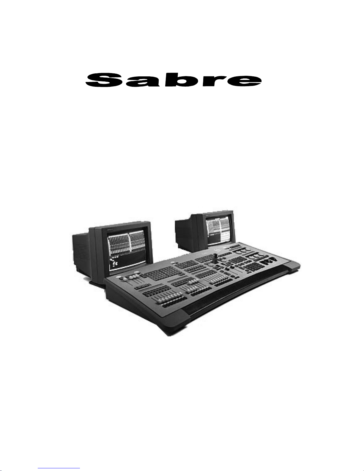
User’s Guide
Compulite R & D Version 2.0
February 1999
Page 2

Table of Contents
Part 1 - General
Chapter 1 Introduction ......................................................................................................... 1-1
Common Terms...............................................................................................................1-3
Editing terms...............................................................................................................1-4
Playback terms............................................................................................................1-4
Console Areas...................................................................................................................1-5
Text conventions...............................................................................................................1-5
Using the User’s Guide.....................................................................................................1-6
Output Conventions.......................................................................................................... 1-6
Chapter 2 General Operation................................................................................................2-1
The Editor Section............................................................................................................2-2
F keys .........................................................................................................................2-2
Programming memorie s...............................................................................................2-2
Editor color key...........................................................................................................2-3
Editor error trapping.................................................................................................... 2-3
Clearing the ed itor.......................................................................................................2-3
Numeric Soft Keys............................................................................................................2-4
Temporary status.........................................................................................................2-4
Paging.........................................................................................................................2-5
Viewing the NSKs.......................................................................................................2-5
Storing and erasing...................................................................................................... 2-5
Parameter Control.............................................................................................................2-7
Crossfaders.......................................................................................................................2-9
Controllers........................................................................................................................2-9
The Joystick......................................................................................................................2-9
General Master.................................................................................................................2-9
Submasters.....................................................................................................................2-10
Freeing Assignm ent s....................................................................................................... 2-10
Menus............................................................................................................................2-11
Acce s sing menus.......................................................................................................2-12
Exiting the menu mode..............................................................................................2-12
Text & the Alphanumeric Keyboard................................................................................2-13
A page of text............................................................................................................2-13
Erasin g text...............................................................................................................2-13
Moving the cursor.....................................................................................................2-13
Using the text keyboard for editing............................................................................2-14
Getting Help...................................................................................................................2-15
System Status.................................................................................................................2-15
Color key for System Status.......................................................................................2-15
What to do in case of disconnection ...........................................................................2-15
Disabling a device.....................................................................................................2-16
Chapter 3 Displays...............................................................................................................3-1
Display Control ................................................................................................................3-2
Display Formats................................................................................................................3-2
Messages and commands.............................................................................................3-3
Stage display...............................................................................................................3-3
The Playback display...................................................................................................3-4
The X-Fade Exam display............................................................................................3-5
Exam Displays..................................................................................................................3-6
Display Macros.................................................................................................................3-7
Programming a Display Macro....................................................................................3-7
Adding text to a Display Macro...................................................................................3-8
Page 3

Sabre
i
i
Using Display Macros.................................................................................................3-8
Deleting a Display Macro............................................................................................3-9
TOPO...............................................................................................................................3-9
Positioning spots on the TOPO map ............................................................................ 3-9
Relocating a spot on the TOPO map.......................................................................... 3-10
Removing a spot fr om the TOPO map ....................................................................... 3-10
Color key for TOPO display...................................................................................... 3-10
Chapter 4 Quick Start...........................................................................................................4-1
Setting Up Sabre...............................................................................................................4-2
Configuring Sabre............................................................................................................ 4-2
Patching...........................................................................................................................4-3
Patching and addressing moving lights........................................................................ 4-3
Creating homogeneous beam movement...................................................................... 4-4
Patching dimmers to channels ..................................................................................... 4-4
Patching scrollers to channels...................................................................................... 4-4
Programming Memories ...................................................................................................4-5
Playback Memories on A/B.............................................................................................. 4-5
Playback chasers .............................................................................................................. 4-6
Part 2 - Basic Editing
Chapter 5 Selecting and Editing Spots.................................................................................. 5-1
Igniting Spots...................................................................................................................5-2
Igniting DMX spots.....................................................................................................5-2
Igniting S-Mix or L-Mix spots.....................................................................................5-3
Ignition exam.............................................................................................................. 5-4
Selecting Spots.................................................................................................................5-5
Changing the number default selection ........................................................................ 5-5
Selecting spots using the numeric keypad.................................................................... 5-5
Selecting more than one spot.......................................................................................5-5
Selecting spots using the Numeric Soft Keys ...............................................................5-6
Canceling a selection u sing NSKs................................................................................ 5-7
Recalling the last selection ..........................................................................................5-7
Selecting spots in the editor and on stage.....................................................................5-7
Mix Editing of Spots.........................................................................................................5-8
Spot Parameters................................................................................................................5-8
Parameter wheels........................................................................................................ 5-8
Trackball .................................................................................................................... 5-9
Assigning values t o pan and tilt ................................................................................. 5-10
Assigning dimm er values ..........................................................................................5-10
Selecting parameters and assigning values................................................................. 5-11
Returning to home values.......................................................................................... 5-16
Copying parameter values......................................................................................... 5-17
Copying a spot position............................................................................................. 5-18
Releasing Spots/Parameters from the Editor.................................................................... 5-19
Releasing a spot from the editor.................................................................................5-19
Releasing a parameter from the editor........................................................................ 5-19
Chapter 6 Selecting and Editing Channels and Scrollers ....................................................... 6-1
Changing the Number Default Selection ........................................................................... 6-2
Selecting Channels........................................................................................................... 6-2
Selecting a single channel............................................................................................ 6-2
Selecting multiple channels.........................................................................................6-3
Selecting a range of channels.......................................................................................6-3
Excluding channels from a range selection...................................................................6-3
Recalling the last selection ..........................................................................................6-4
Grabbing channels in the editor and on stage ............................................................... 6-4
Assigning inten sit y levels............................................................................................ 6-4
Page 4

Sabre
iii
Releasing channels from the editor ..............................................................................6-5
Selecting and Editing Scrollers.......................................................................................... 6-6
Assigning frame values ...............................................................................................6-6
Chapter 7 Programming Memories.......................................................................................7-1
Overview..........................................................................................................................7-2
Resetting the Ed itor ..........................................................................................................7-2
Programming with Spots...................................................................................................7-2
All If Dim...................................................................................................................7-3
Programming with Channels .............................................................................................7-4
Programming with Scrollers..............................................................................................7-4
Sequential Memory Programming....................................................................................7-5
Using the Copy Function...................................................................................................7-5
Copying all parameters from the editor ........................................................................7-5
Copying selected parameters from the editor................................................................7-6
Copying spot parameters from a memory.....................................................................7-6
Copying selected parameters from a memory...............................................................7-6
Copying channel intensities from the editor..................................................................7-7
Copying channel intensities fro m a memory.................................................................7-7
Copying scroller frames from the editor.......................................................................7-7
Copying scroller frames from a memory...................................................................... 7-7
Using the Call Function ....................................................................................................7-8
Using Call to store current output ................................................................................7-8
Using Call and assignments to program memories........................................................7-9
Examining Memories, Channels, & Spots..........................................................................7-9
Examining memories...................................................................................................7-9
Examining channels.................................................................................................. 7-10
Examining spots ........................................................................................................7-11
Text for Memories..........................................................................................................7-12
Fade Times .....................................................................................................................7-12
Assigning fade tim es t o a new memory...................................................................... 7-14
Assigning fade tim es t o an exi stin g memor y...............................................................7-14
Assigning fade tim es t o a range of memor i es .............................................................7-15
Assigning fade times t o non-sequential memories ......................................................7-15
Modi f ying time ass ignme nts......................................................................................7-15
Converting Memories to an Editor Group.......................................................................7-16
Converting a memory to group while editor is in idle.................................................7-16
Converting a memory to group when the editor is active.............................................7-17
Mask..............................................................................................................................7-18
Selecting sequential memories for Mask.................................................................... 7-18
Sele cting non-seque ntial memories............................................................................7-19
Assigning a Mask to a controll er................................................................................7-19
Using Mask for controller assignments......................................................................7-19
Using Mask with Libraries.........................................................................................7-19
Inse rt ing a Memory.........................................................................................................7-20
Programming a Blackout Cue..........................................................................................7-20
Programming in Blind Mode ...........................................................................................7-21
Clearing the blind editor............................................................................................ 7-21
Memory Operations in the Editor ....................................................................................7-22
Renami n g and exch anging memorie s.........................................................................7-22
Copying memories ...................................................................................................7-22
Erasin g memorie s......................................................................................................7-23
Memory Operations menu...............................................................................................7-24
Renami n g memorie s..................................................................................................7-24
Copying a memory....................................................................................................7-24
Dele tin g memorie s....................................................................................................7-25
Clear console.............................................................................................................7-25
Remain Dim...................................................................................................................7-26
Page 5

Sabre
i
v
Chapter 8 Memory Modification..........................................................................................8-1
Basic Memory Modification ............................................................................................. 8-2
STORE STORE................................................................................................................8-3
Editi ng memorie s live on-stage....................................................................................8-3
Delta................................................................................................................................ 8-4
Creating a delta via memory modification.................................................................... 8-4
Creating a delta with STORE STORE ......................................................................... 8-5
Including Libraries in delta..........................................................................................8-6
Examining a delta .......................................................................................................8-6
Function keys for delta application..............................................................................8-7
Applying delta for memory modification..................................................................... 8-8
Automatic delta tracking............................................................................................. 8-8
Erasin g a d elta .......................................................................................................... 8-11
Releasing Channels, Spots, Scrollers...............................................................................8-11
Releasing spots .........................................................................................................8-11
Releasing channels.................................................................................................... 8-11
Releasing scrollers.................................................................................................... 8-11
Releasing channels from a range of memories............................................................ 8-12
Releasing scrollers from a range of memories ............................................................ 8-12
Chapter 9 Libraries..............................................................................................................9-1
Overview..........................................................................................................................9-2
Programming a Library....................................................................................................9-3
Overwriting a Library..................................................................................................9-3
Storing more than 1 Library.........................................................................................9-4
Programming a Library using a memory......................................................................9-4
Text for Libraries.............................................................................................................. 9-5
Storing a new Library with text ................................................................................... 9-5
Adding text to an existing Library................................................................................9-5
Examining Libraries .........................................................................................................9-5
Viewing the Library list...............................................................................................9-6
Examining a selected Library...................................................................................... 9-6
Library tracking.......................................................................................................... 9-6
Editing Libraries...............................................................................................................9-7
Updating a Library...................................................................................................... 9-7
Adding spots to a Library............................................................................................ 9-7
Removing spots from a Library.................................................................................. 9-8
Updating a library via the STORE STORE function..................................................... 9-8
Erasin g a Li brary.............................................................................................................. 9-8
Programming Memories with Libraries ............................................................................. 9-9
Using Libraries for spot selection ..............................................................................9-10
Copying from a Library.............................................................................................9-10
Chapter 10 Loops & Links................................................................................................. 10-1
Loops............................................................................................................................. 10-2
Programming an automatic continuous Loop ............................................................. 10-2
Programming a manual continuous Loop................................................................... 10-3
Programming a finite Loop........................................................................................ 10-3
Programming an autofollow Loop..............................................................................10-4
Programming a follow-on cue....................................................................................10-4
Exiting a automatic or manual continuous Loop......................................................... 10-5
Erasing a Loop assignment........................................................................................10-5
Erasing an auto follow Loop assignment.................................................................... 10-5
Links.............................................................................................................................. 10-6
Programming a Link between two memories ............................................................. 10-6
Programming a Link among a group of memories...................................................... 10-6
Erasin g a Link assi gnment.........................................................................................10-6
Viewing Links.......................................................................................................... 10-7
Page 6

Sabre
v
Part 3- File Management and Printing
Chapter 11 Data Storage, Retrieval, & Printing...................................................................11-1
Navigating the Hard Disk................................................................................................ 11-2
Navigating to a “higher” directory..............................................................................11-2
Returning to the Root directory..................................................................................11-4
Recording Show Files.....................................................................................................11-5
File management on the hard disk ..............................................................................11-5
Recording a show file to the hard disk........................................................................11-7
Recording to a floppy disk.........................................................................................11-8
Autosave.........................................................................................................................11-9
Determining the number of files saved.......................................................................11-9
Enabling the Autosave function...............................................................................11-10
Disabling the Autosave function..............................................................................11-10
Manually triggering an Autosave.............................................................................11-10
Restoring (loading) Autosave files...........................................................................11-11
Locking and unlocking Autosave files......................................................................11-11
Deleting all generations of Autosave files ................................................................11-12
Loading show files ........................................................................................................11-13
Selecting a show file from the hard disk...................................................................11-13
Selecting a show file from the floppy disk................................................................11-14
Load options........................................................................................................... 11-14
Load Warning messages..........................................................................................11-15
Loading QLists.......................................................................................................11-15
Warning Difference.................................................................................................11-17
Deleting Show Files and Directories..............................................................................11-18
Deleting a show file.................................................................................................11-18
Dele tin g a d irecto ry.................................................................................................11-18
Printi n g ....................................................................................................................... ..11-19
Part 4 - Playback
Chapter 12 The Crossfaders................................................................................................12-1
Overview........................................................................................................................12-2
Assigning Memori es .......................................................................................................12-3
Sequencing Memories.....................................................................................................12-5
Assigning the Editor Group.............................................................................................12-6
Adding spots/channels to grp assignment...................................................................12-6
Removing spots/channels from a grp assignment........................................................ 12-6
Freeing assig n ments........................................................................................................12-7
The Playback Keys .........................................................................................................12-7
Modifying the Fade Rate.................................................................................................12-8
Using the Rate wheels ...............................................................................................12-8
Configuring the Crossfader .............................................................................................12-9
Configure B and D as Rate Faders .............................................................................12-9
Configure as split crossfaders....................................................................................12-9
Disable B and D......................................................................................................12-10
Chapter 13 Controllers/Chasers, Submasters, & Joystick.....................................................13-1
Overview........................................................................................................................13-2
Assignment keys .......................................................................................................13-2
Bump Buttons...........................................................................................................13-3
Control priority..........................................................................................................13-3
Controller Displays.........................................................................................................13-3
Stage display.............................................................................................................13-3
LCD displays............................................................................................................. 13-5
Assigning Memori es .......................................................................................................13-5
Page 7

Sabre
v
i
Assigning a single mem ory........................................................................................ 13-5
Assigning a range of memories.................................................................................. 13-6
Assigning a group of memori es ................................................................................. 13-6
Fading memory assignments ..................................................................................... 13-6
Assigning Spots.............................................................................................................. 13-7
Assigning a range of spots to a controller................................................................... 13-7
Adding a spot to a controller assignment....................................................................13-8
Removing a spot from a controller assignment........................................................... 13-8
Removing a parameter from a controller assignment.................................................. 13-8
Assigning Spot Param et ers ............................................................................................. 13-9
Assigning Channels...................................................................................................... 13-10
Assigning channels with full range fading................................................................ 13-10
Assigning chann el s with proscr i bed intensity ........................................................... 13-11
Adding channels to existing assignments................................................................. 13-11
Removing channels from existing assignments........................................................ 13-11
Assigning Scroll ers....................................................................................................... 13-12
Freeing Controller Assignments.................................................................................... 13-13
Freeing selected assignments................................................................................... 13-13
Freeing assig n ments o n a range of controlle rs.......................................................... 13-13
Blacking Out Controller Output.................................................................................... 13-14
Blackout all controllers ...........................................................................................13-14
Examining Controll er Assignments ............................................................................... 13-15
Chasers ........................................................................................................................ 13-16
Chaser control......................................................................................................... 13-16
LED color codes...................................................................................................... 13-16
Display and exam.................................................................................................... 13-17
Assigning chaser s.................................................................................................... 13-17
Chase r r ate.............................................................................................................. 13-18
Fading within chasers.............................................................................................. 13-19
Joining chasers to respond to Go..............................................................................13-20
Assigning Effects.......................................................................................................... 13-20
Fading with LTP...........................................................................................................13-21
Submasters................................................................................................................... 13-22
Assigning chann el s and spots to a submaster ........................................................... 13-22
Releasing an ass ignme nt..........................................................................................13-22
Submastering A/B and C/D..................................................................................... 13-23
Canceling Submaster control of a crossfader............................................................13-23
Joystick........................................................................................................................ 13-24
Assigning spots....................................................................................................... 13-24
Freeing spots........................................................................................................... 13-24
Chapter 14 Q-Keys ............................................................................................................ 14-1
Overview........................................................................................................................14-2
Assignments to Q-Keys .................................................................................................. 14-2
Assigning memori es.................................................................................................. 14-2
Assigning groups ...................................................................................................... 14-4
Freeing Q-Keys.............................................................................................................. 14-6
Playing Back Q-Key Assignm en t s .................................................................................. 14-6
Enabling/disabling Pile On........................................................................................ 14-6
Q-Keys Display.............................................................................................................. 14-7
Chapter 15 Control Priority ................................................................................................ 15-1
Control Priority............................................................................................................... 15-2
Default Control Priority..................................................................................................15-2
Device Priority Menu ..................................................................................................... 15-3
Changing the playback device priority....................................................................... 15-3
Assigning the same priori t y code - LTP .....................................................................15-4
Reassigning the default map......................................................................................15-6
Editing Priority maps................................................................................................ 15-6
Page 8

Sabre
vi
i
Erasing priority maps ................................................................................................15-6
Working with LTP..........................................................................................................15-7
Enabling LTP............................................................................................................15-7
Disabling LTP...........................................................................................................15-7
Changing the priority stack during playback...............................................................15-8
Bumping A/B or C/D to top priority........................................................................... 15-8
Storing a current priority configuration......................................................................15-9
Switching the Current Priority Map.................................................................................15-9
Part 5 - Advanced Editing
Chapter 16 Q-Lists.............................................................................................................16-1
Overview........................................................................................................................16-2
Storing Memories in Q-Lists...........................................................................................16-2
Copying from Q-List to Q-List........................................................................................16-3
Copying in the editor.................................................................................................16-3
Examining Q-Lists..........................................................................................................16-3
Assigning Loops to Q-Lists.............................................................................................16-4
Assigning automa tic Loops to Q-Lists........................................................................16-4
Assigning manual Loops to Q-List s ...........................................................................16-4
Assigning finit e Loops to Q-Lists ..............................................................................16-5
Changing the Default Q-List...........................................................................................16-5
Using the numeric keypad..........................................................................................16-5
Using the Numeric Soft Keys in Q-List mode............................................................16-5
Erasing Q-Lists...............................................................................................................16-6
Playing back Q-Lists.......................................................................................................16-6
Assigning a Q-List ....................................................................................................16-6
Fading to a selected memory in a Q-List....................................................................16-6
Fading to a memory in the default Q-List...................................................................16-7
Fading to a memory from a selected Q-List................................................................16-7
Chapter 17 Groups ............................................................................................................. 17-1
Overview........................................................................................................................17-2
Programming Groups......................................................................................................17-2
Programming Groups in blind mode ..........................................................................17-2
Programming Groups using current lighting state.......................................................17-2
Programming an empty Group ...................................................................................17-3
Modifying Groups ..........................................................................................................17-4
Adding spots and channels to Groups.........................................................................17-4
Removing spots/channels from Groups ......................................................................17-4
Erasing Groups...............................................................................................................17-4
Examining Groups ..........................................................................................................17-5
Text for Groups ..............................................................................................................17-5
Erasin g text...............................................................................................................17-6
Using Groups..................................................................................................................17-6
Releasing spots and channels from the selection......................................................... 17-6
Chapter 18 Palettes.............................................................................................................18-1
Overview........................................................................................................................18-2
Programming a Palette...................................................................................................18-2
Text for Palettes..............................................................................................................18-3
Examining Palettes.........................................................................................................18-4
Viewing the Palette list..............................................................................................18-4
Examining a selected Palette......................................................................................18-4
Modifying Palettes..........................................................................................................18-5
Adding a channel.......................................................................................................18-5
Adding a spot............................................................................................................18-6
Adding spot parameters.............................................................................................18-6
Page 9

Sabre
vii
i
Modi f ying assigned valu es........................................................................................18-7
Removing elements from a Palette.............................................................................18-8
Copying Palettes............................................................................................................. 18-9
Erasin g a Palette............................................................................................................. 18-9
Applying Palettes ......................................................................................................... 18-10
Palette files...................................................................................................................18-11
Loading dedicated Palette files................................................................................ 18-11
Loading Palettes from show files............................................................................. 18-12
Recording dedicated Palette files............................................................................. 18-12
Chapter 19 Filter................................................................................................................ 19-1
Overview........................................................................................................................19-2
Programming a Filter...................................................................................................... 19-2
Programming a Filter using editor selections..............................................................19-2
Programming a Filter from library parameters............................................................19-3
Programming a Filter using memories....................................................................... 19-3
Modifying Filters............................................................................................................19-4
Adding channels to a Filter........................................................................................ 19-4
Adding spots to a Filter ............................................................................................. 19-4
Adding Text to Filters.....................................................................................................19-4
Erasing Filters................................................................................................................19-5
Examining Filters........................................................................................................... 19-5
Viewing Filter assignments ....................................................................................... 19-5
Viewing a selected Filter........................................................................................... 19-5
Viewing the Fil ter list................................................................................................19-5
Filters and Playback Devices...........................................................................................19-6
Assigning a Filter to a playback device...................................................................... 19-6
Assigning an Invert Filter to a playback device.......................................................... 19-6
Remo ving a Filter assign ment ................................................................................... 19-6
Filte rs and the Editor ...................................................................................................... 19- 7
Assigning a Filter to the editor................................................................................... 19-7
Assigning an Invert Filter to the editor....................................................................... 19-7
Remo ving a Filte r as s i gnment f rom the editor............................................................ 19-7
Storing memories with STORE STORE and Filters......................................................... 19-8
Part 6 - Advanced Functions
Chapter 20 Effects ............................................................................................................. 20-1
Overview........................................................................................................................20-2
Acce s sing the Ef f ect Editor............................................................................................. 20-2
Exiting the Effect Editor............................................................................................20-3
Effect Attributes............................................................................................................. 20-4
Primitive ................................................................................................................... 20-4
Base..........................................................................................................................20-6
Size...........................................................................................................................20-7
Delta......................................................................................................................... 20-8
Rate........................................................................................................................ 20-10
Default values for Rate, Size, and Delta................................................................... 20-11
Offset...................................................................................................................... 20-11
Duty Cycle.............................................................................................................. 20-15
Programming in the Effect Editor.................................................................................. 20-17
Adding Parameters.................................................................................................. 20-17
Copying timing attributes........................................................................................ 20-17
Assigning Effects to channels.................................................................................. 20-18
Assigning Effects to scr oll ers.................................................................................. 20-18
Returning to the Effect Editor.................................................................................. 20-18
Storing Effects as Memories......................................................................................... 20-19
Examining memories and Effects.............................................................................20-19
Page 10

Sabre
i
x
Releasing an Effect from a memory......................................................................... 20-20
Storing an Effect Palette................................................................................................20-20
Assigning text t o an Effect Pal et te ...........................................................................20-21
Erasin g Effec t Palettes.............................................................................................20-21
Examining Effect Palettes........................................................................................20-22
Using Effec t Palettes.....................................................................................................20-22
Storing Memories....................................................................................................20-22
Playing Back Effects.....................................................................................................20-23
On the Crossfaders ..................................................................................................20-23
On the Controllers ................................................................................................... 20-23
Loading, Recording, and Deleting Effect Files...............................................................20-24
Loading Effect files.................................................................................................20-24
Loading Effect files from a show file....................................................................... 20-26
Recording dedicated Effect files............................................................................... 20-26
Dele tin g Effec t f iles.................................................................................................20-26
The Effects Package......................................................................................................20-27
Modi f ying preprogram med Effects ..........................................................................20-27
Using Effects for programming....................................................................................20-28
Freezing an Effect ...................................................................................................20-28
Releasing the freeze state......................................................................................... 20-28
Programming Libraries using freeze effect...............................................................20-28
Types of Primitives.......................................................................................................20-29
Chapter 21 Part Qs.............................................................................................................21-1
Overview........................................................................................................................21-2
Programming Memories with Parts .................................................................................21-3
Programming a Part with spots..................................................................................21-3
Programming a Part with spot parameters.................................................................. 21-3
Programming a Part with channels.............................................................................21-4
Programming a Part with scrollers .............................................................................21-4
Dividing a Memory into Parts.........................................................................................21-5
Adding a Part to a Memory............................................................................................. 21-5
Modi f ying a Part.............................................................................................................21-6
Removing channels/spots from Parts..........................................................................21-6
Removing Part assignments.......................................................................................21-6
Modi f ying time ass ignme nts......................................................................................21-7
Using Part Assignm ent s as Groups..................................................................................21-7
Chapter 22 Macros.............................................................................................................22-1
Overview........................................................................................................................22-2
The Macro Menu............................................................................................................22-2
Programming a Macro for a chaser ............................................................................22-2
Modifying Macros.....................................................................................................22-3
Linking Macros.........................................................................................................22-3
Special Macros for special functions..........................................................................22-4
Adding text to Macros...............................................................................................22-6
Erasin g a Macro........................................................................................................22-6
Programming Macros Live with Teach Macro .................................................................22-7
Operating Macros...........................................................................................................22-8
Operating Macros......................................................................................................22-8
Operating Macros using the numeric keypad..............................................................22-8
Chapter 23 Snap.................................................................................................................23-1
Overview........................................................................................................................23-2
Programming Snaps........................................................................................................23-2
Overwriting Snaps.....................................................................................................23-3
Adding Text to Snaps......................................................................................................23-4
Examining Snaps............................................................................................................23-4
Viewing the Snap list.................................................................................................23-4
Page 11

Sabre
x
Examining selected Snaps......................................................................................... 23-4
Operating Snaps in Non Forcing Mode............................................................................23-5
Using the numeric keypad .........................................................................................23-5
Using the NSKs ........................................................................................................ 23-5
Operating Snap in Forcing Mode.................................................................................... 23-5
Using the numeric keypad .........................................................................................23-6
Using the NSKs ........................................................................................................ 23-6
Snaps and the A/B Crossfade r......................................................................................... 23-6
Disabling Snaps to A/B............................................................................................. 23-6
Erasin g a Snap................................................................................................................ 23-7
Using the numeric keypad .........................................................................................23-7
Using the NSKs ........................................................................................................ 23-7
Chapter 24 Events..............................................................................................................24-1
Overview........................................................................................................................24-2
Changing the Q-List ....................................................................................................... 24-2
Events for crossfaders..................................................................................................... 24-2
Events for controllers...................................................................................................... 24-4
Assigning Q-List s ..................................................................................................... 24-4
Assigning a chaser .................................................................................................... 24-5
Events for the Joystick.................................................................................................... 24-7
Assigning spots to th e Joystick .................................................................................. 24-7
Assigning spots to th e Joystick using Groups ............................................................. 24-7
Freeing Joystick assignments.....................................................................................24-8
Events for Macro ............................................................................................................ 24-9
Events for Submasters .................................................................................................. 24-10
Dele tin g an Event......................................................................................................... 24-12
Dele tin g Events in t he ed itor ................................................................................... 24-12
Adding operations to an Event...................................................................................... 24-13
Adding text to an Event................................................................................................ 24-13
Examining an Event...................................................................................................... 24-14
Playing Back Events..................................................................................................... 24-14
Assigning an Event to a memory ............................................................................. 24-14
Play ing b ack an Event using the editor..................................................................... 24-15
Chapter 25 Leader .............................................................................................................25-1
Overview........................................................................................................................25-2
The Leader Menu...........................................................................................................25-2
Setting up for the Leader function..............................................................................25-2
Corre cting in accurate pl acemen t................................................................................25-3
Testing Leader set up ................................................................................................25-3
Using Leader during Playback........................................................................................ 25-4
Assigning lead er/ follower sp ots................................................................................. 25-4
Adding follower spots using the numeric keypad....................................................... 25-5
Adding follower spots u sing the NSKs ...................................................................... 25-5
Releasing follower spots assignment.......................................................................... 25-6
Changing the Leader assignment............................................................................... 25-6
Delay assignments for Leader....................................................................................25-7
Operating Leader ......................................................................................................25-8
Relative Leader Motion..................................................................................................25-9
Programming a re lative mo tion leade r....................................................................... 25-9
Canceling the relative motion leader.......................................................................... 25-9
Change Venue.............................................................................................................. 25-10
Updating a Library.................................................................................................. 25-10
Updating selected spots in Library........................................................................... 25-11
Fine tuning spot positions........................................................................................ 25-11
Updating memories ................................................................................................. 25-11
Updating selected spots in a memory....................................................................... 25-12
Page 12

Sabre
x
i
Part 7 - Configuration and Patching
Chapter 26 System Configuration......................................................................................26-1
Overview........................................................................................................................26-2
Accessing Service Tools............................................................................................26-2
Configuring in Service Tools...........................................................................................26-2
Communication params.............................................................................................26-3
Toggling CRT number...............................................................................................26-3
Configuring for channels, spots, dimmers ..................................................................26-4
Special Functions......................................................................................................26-5
Special Numbers ....................................................................................................... 26-7
System Parameters..........................................................................................................26-9
Definable parameters.................................................................................................26-9
Exit to service tools.................................................................................................26-11
Print menu screen....................................................................................................26-11
Default Device List..................................................................................................26-12
Chapter 27 Spot Management and Patching........................................................................ 27-1
Mix Output Menu...........................................................................................................27-2
Mix Output menu display..........................................................................................27-2
Patching spot numbers...............................................................................................27-4
Assigning output a ddresses........................................................................................27-4
Device definitions.....................................................................................................27-8
The Device Pools.....................................................................................................27-19
The Patch menu............................................................................................................27-22
Assigning a new patch position................................................................................27-22
Returning to the default position..............................................................................27-22
Chapter 28 Channel and Scroller Patching..........................................................................28-1
Channel Patch.................................................................................................................28-2
Connector Information ..............................................................................................28-2
Soft patching dimmers to channels.............................................................................28-3
Clearing patch assignments........................................................................................28-5
Restoring the default patch ........................................................................................28-6
Exchanging dimmers.................................................................................................28-6
Assigning dimm er curves ..........................................................................................28-7
Disabling General Master control............................................................................... 28-7
Enabling General Master control................................................................................28-8
Viewing free dimmers...............................................................................................28-8
Testing channels and dimmers...................................................................................28-8
Scroller Patch .................................................................................................................28-9
Selecting a scroller ..................................................................................................28-10
Patching a scroller to a control channel....................................................................28-10
Defining a dark gel frame........................................................................................28-10
Canceling a dark gel assignment..............................................................................28-11
Changing the number of frames...............................................................................28-11
Setting up frames..................................................................................................... 28-11
Copying the scroller setup.......................................................................................28-12
Back door to Channel Patch.....................................................................................28-12
Part 8 - Communication Protocols
Chapter 29 MIDI................................................................................................................29-1
Configuring the System for MIDI....................................................................................29-2
Enabling/Disabling MIDI................................................................................................29-3
Turning MIDI on.......................................................................................................29-3
Turning MIDI off......................................................................................................29-3
The MIDI Menu .............................................................................................................29-3
Page 13

Sabre
xi
i
Enabling keys and controllers.................................................................................... 29-4
Editing MIDI data for keys and controllers................................................................ 29-4
MIDI Macro ................................................................................................................... 29-5
MIDI Sync.....................................................................................................................29-6
Enabling/disabling MIDI Sync.................................................................................. 29-6
Setti ng up the master cons ole.....................................................................................29-6
Setting up the slave console....................................................................................... 29-7
Standard MIDI Codes..................................................................................................... 29-8
Chapter 30 SMPTE............................................................................................................ 30-1
Overview........................................................................................................................30-2
Configurin g Sabre for SMPTE oper ation......................................................................... 30-2
Configuring for the number of frames........................................................................30-3
Using the Internal SMPTE Clock ....................................................................................30-3
Color key for the SMPTE clock.................................................................................30-4
Turning on the SMPTE function................................................................................ 30-4
Turning off the SMPTE functi on ............................................................................... 30-4
Starting the SMPTE clock.........................................................................................30-4
Stopping the SMPTE clock........................................................................................ 30-4
Resetting the SMPTE clock to 0 ................................................................................ 30-5
Resetting and starting the clock .................................................................................30-5
Setting the SMPTE clock to a selected time............................................................... 30-5
Setting the clock to a selected time and starting ......................................................... 30-6
Setting the clock using the A/B Rate wheel................................................................30-6
Assigning Time Codes Usin g Tea ch................................................................................ 30-7
Assigning time codes to Event s ................................................................................. 30-7
Assigning time codes to memor i es ............................................................................. 30-8
Exiting the Teach function.........................................................................................30-8
Manually Assignin g SMPTE Tim e.................................................................................. 30-9
Units of time format................................................................................................. 30-9
Assigning SMPTE code to memories.........................................................................30-9
Modi f ying assignments f or memor ies...................................................................... 30-10
Assigning SMPTE codes to Events.......................................................................... 30-14
Quick Reference for assignment & modification ...................................................... 30-15
Erasing SMPTE assignments ........................................................................................ 30-15
Play ing b ack Eve nts and memories............................................................................... 30-16
Enabling the console for playback...........................................................................30-16
Chapter 31 DMX Input ...................................................................................................... 31-1
Overview........................................................................................................................31-2
Configurin g the System for DMX Input .......................................................................... 31-2
Patching DMX Input ...................................................................................................... 31-3
Patching input channels.............................................................................................31-4
Assigning DMX input as playback submasters ........................................................... 31-4
Clearing input patch assignments...............................................................................31-5
Returning the default patch........................................................................................ 31-5
Examining DMX input assignments .......................................................................... 31-5
Assigning Macros to DMX input...............................................................................31-5
Chapter 32 Ethernet........................................................................................................... 32-1
Ethernet.......................................................................................................................... 32-2
A Typical Ethernet Configuration.............................................................................. 32-2
Network Settings............................................................................................................ 32-3
Mapping the Network Drives..........................................................................................32-4
Disabling/Enabling local output.................................................................................32-4
Assigning an ID number............................................................................................ 32-5
Virtual Connector Editing ......................................................................................... 32-5
Assigning IP addr esses ................................................................................................... 32-6
What Are Virtual Connectors?........................................................................................32-7
Page 14

Sabre
xiii
Appendices
Appendix A Service Tools...................................................................................................A-1
Accessing Service Tools.................................................................................................. A-2
Main Menu ...................................................................................................................... A-2
Diagnostics......................................................................................................................A-2
Upgrading Software.........................................................................................................A-3
Using the Software Upgrade option ............................................................................A-3
Upgrading software under Disk Operations................................................................. A-4
Disk Operations...............................................................................................................A-5
Forma tting disk ettes................................................................................................... A-5
Filer...........................................................................................................................A-5
Recording the system configuration............................................................................A-6
Loading the system configuration............................................................................... A-7
Recording image files to the Hard Disk.......................................................................A-8
Loading image files from the Hard Disk..................................................................... A-8
Back Door to Service Tools..............................................................................................A-9
Appendix B Console Key Index .......................................................................................... B-1
Page 15

CHAPTER 1
INTRODUCTION
The Compulite Sabre offers designers and operators quick and easy access to the
parameters of automated luminaries, conventional dimmers, and color scrollers. Sabre
controls up to 196 moving lights and up to 1024 channels for dimmers, color scrollers, or
any other device controlled by DMX 512.
Sabre includes many user friendly functions that allow you to customize the system to suit
your needs .
This User’s Guide contains 32 chapters and 2 appendices.
The User’s Guide is divided into 8 parts.
Part 1 - Genera l
•
Chapter 1 Intr oduction
•
Chapter 2 General Operation
A concise overview of operational features, such as the Editor, Playback Devices, Soft
Keys, Display Formats, and On Line Help.
•
Chapter 3 Di spl a ys
Descriptions of the different displays available in Sabre and operating instructions for
Display control.
•
Chapter 4 Quick Start
This chapter provides operating instructions for the most basic functions on Sabre. Its
purpose is to provide quick instruction to operators familiar with lighting consoles.
Part 2 – Basic Programming
•
Chapter 5 Selecting and Editing Spots
Operating instructions for basic moving light (spot) selection, advanced selection
sequences, spot parameter selection, and assigning parameter values.
•
Chapter 6 Selecting and Editing Channels and Scrollers
Operating instructions for basic channel and scroller selection, advanced selection
sequences, and assigning dimmer and frame values.
•
Chapter 7 Programming Memories
Basic programming functions, including using the Call function, how to convert
memories to editor groups, assigning Fade Times, programming in Blind mode, and
inserting memories.
•
Chapter 8 Modifying Memories
Operating instructions for basic memory modification, quick modification for
memories assigned to playback devices using the STORE STORE function, and Delta
tracking modification.
•
Chapter 9 Libraries
Operating instructions for programming, modifying, and using Libraries.
•
Chapter 10 L oops & Links
Programming memories with Loops to run as Chasers on the controllers or on the
crossfader. Linking non-sequential memories.
Page 16

Common Terms1-2
Part 3 – File Management and Printing
•
Chapter 11 Data Storage, Retrieval, & Printing
How to record and Load show files from the Hard Disk and from floppy diskettes,
navigating the Hard Disk, printing options.
Part 4 - Playback
•
Chapter 12 T he Cr ossfaders
Making assignments to the A/B crossfader, playback using automatic Go commands
or manual operation, and automatic Rate control.
•
Chapter 13 Controllers, Submasters, and Joystick
Assigni ng memories, groups, and C hasers to th e C on t rollers. Using the aut omatic Go
and manual playback operations. Rate control for Chasers. Assigning groups of spots
and channels to Submasters. Using the Joystick for pan and tilt control.
•
Chapter 14 Q-Keys
Using the Numeric Soft Keys in Q-Key mode for memory playback.
•
Chapter 15 Control Priority
A description of Sabre’s default control and using LTP.
Part 5 – Advanced Editing
•
Chapter 16 Q-Lists
Arran ge your memories in Q-Lists for efficient playback. Sabre supports 100 Q-Lists.
•
Chapter 17 Groups
Program Groups for quick spot and channel selection. Sabre supports 999 Groups.
•
Channel 18 Palettes
Programming Palettes and using Palettes for quick editing. Palettes are a non-tracking
data base for spot parameter values, scroller frame values, and channel intensity.
•
Channel 19 Filter
Programming memories with parts. Each Part can have unique delay and fade times.
Part 6 – Advanced Topics
•
Channel 20 Effects
Modifying pre-programmed Effect Palettes, programming custom Effects, and Effects
playback,
•
Channel 21 Par t Qs
Programming memories with parts. Each Part can have unique delay and fade times.
•
Chapter 22 Macros
Sabre supports up to 999 Macros. Operating in str uctions for programming Macros
blind, in the Macro menu, or live using the Teach macro function.
•
Chapter 23 Sna p
Store ‘snapshots’ of all playback device assignments and their fade status. Snaps are
analogous to preset pages for Controllers. Sabre supports 99 Snaps.
•
Channel 24 Event
Program Events to operate multiple assignment and playback commands. Events can
be operated when assigned to memories sequencing on the A/B crossfader, in the
editor, or using SMPTE.
•
Chapter 25 Leader
Use the Leader setup for quick simple effects. The Change Venue option
automatically updates Libraries.
Page 17

Common Terms 1-3
Part 7 –Configuration and Patching
•
Chapter 26 Sy stem Configuration
General system Configuration in Service Tools and using operator definable system
parameters in the System Parameters menu.
•
Chapter 27 Spot M ana g e ment and Pat c hing
The Mix Output menu provides functions to patch moving light type to control
numbers, assign DMX outp ut addresses, define device profiles.
•
Chapter 28 Channel and Scroller Patching
The Channel Patch provides functions for soft patching dimmers and channels,
assigning dimmer curves, assigning proportional levels to dimmers, examining patch
assignments. The Scroller Patch provides easy functions for setting up frames,
assigning control channels to scrollers, and copying scroller set ups.
Part 8 - Communication Protocols
•
Chapter 29 M IDI
Enable MIDI communication and edit MIDI codes in the MIDI menu. The MIDI
synch option allows a second lighting console to synchronize crossfade operations
with the main console.
•
Chapter 30 SM PTE
Assign SMPT E time codes to Events using the live Teach function and enable Sabre
for automatic operation using SMPTE.
•
Chapter 31 DM X Input
Patch DMX Input cha nnels to operat e l ocal con sole ch annels or m a cros.
•
Chapter 32 Ethernet
An introduction to Ethernet.
Appendices
•
Appendix A Service Tools
Operating instructions for disk formatting, the Hardware diagnostics tool, and
software upgrade functions in Service Tools.
•
Appendix B Panel Layout
A short description of each panel key arranged in alphabetical order.
Common T erms
Three major capabilities are basic to the lighting console: editing, playback, and patching.
Editing is the ability to select channels or moving lights, assign values, and record the
resulting lighting state as a memory (cue). All functions related to the playback structure
of the show, such as Event assignments, Snaps, loops, and Links are part of the editing
functions.
Playback is the ability to replay all the show data that you have created while editing.
Patching includes all of the patching functions which instruct the system how to
communicate with conventional projectors, color scrollers, moving lights, and other
DMX512 protocol elements that a re controlled by t he lighting console.
Page 18

Common Terms1-
4
Editing terms
Here a few terms common to all Compulite consoles.
• Chann el - The control channel for DMX512 devices, which are n ot moving devices.
These include conventional projectors , color scr ol lers, s moke mach ines, etc.
• Delta - A tool for memory modification.
• Erase - Delete selected data.
• Frame - Scroller frame.
• Intensity - Dimmer intensity of channels and spots.
• Libraries - Gobo, Color, a nd Position libraries form a database used when
programming memories.
• Memory - is analogous to cue. The group in the editor, comprising the lighting state
on-stage, is stored as a memory. Memories are then played back.
• Modify - Change stored information and fade rates.
• Parameters - The attributes of moving devices.
• Present or active (in the editor) - Channels and spots that are displayed in white.
Everything present/active in the editor is included when recording a memory.
• Q List - Q Lists are independent entities. Each Q List can contain memories
numbered from 0.1 to 999.9.
• Selected (in the editor) - Channels and spots that are displayed in red and therefore
can be assigned intensity or scroller values.
• Spot – Movin g lig ht
• Store - Save the information in the editor.
• Value - The numerical value assigned to a parameter or a dimmer.
Playback terms
• End Stop - When crossfaders or the controllers are at either 0% or 100%.
• Go - Initiate an automatic crossfade, controller fade, or chaser run.
• Hold - Stop any fade or chaser in progress.
• Multifade - Initiate a fade to the next memory in sequence before the fade in progress
is complete.
• Off the End Stop- When the crossfaders or the controllers are at more than 0% or less
than 100%.
• Rate - The rate at which channels and spots fade in or out during a crossfade. The rate
at which a chaser runs.
• Sequence - The numerical sequencing of the memories on the A/B or C/D crossfaders.
• Step - Manually moving from the current memory to the next memory of a chaser.
Page 19

Console Areas 1-5
Console Areas
Editor sect ion
Numeric keypad for number selections
All basic programming keys
Keys for display control.
Numeric Soft Key sect ion
50 Numeri c Soft Keys
Numeric Soft key m ode keys
Parameter contro l
The trackball
6 horizontal parameter wheels
2 vertical parameter wheels
Parameter selection keys with LEDs
Wheel bank selection keys, LED parameter displays
LED spot type window
Keys for trackball control.
Crossfader section
A/B crossfader with LCD windows for current and incoming memories
C/D crossfader with LCD windows for current and incoming memories
Crossfade command keys
Rate Wh eels
Rate wheel selection keys
Bar graphs for each crossfader showing the rate and level.
The Co ntroller sectio n
24 controllers
Each controller has a bump button
Assignm ent keys for each controll er that a re also used for chaser commands
3 LED displays with 2 display modes
3 dedicated inhibit submasters
A General Master with a blackout key
Text conventions
• Front panel KEYS are typed in BOLD and are contained in square brackets.
• Menus are in capitalized like names.
• Messages are in italics.
• # refers to a number entered on the numeric keypad.
Page 20

Using the User’s Guide1-6
• NSK refers to the Numeric Soft Keys.
• Command line refers to the sequence of keystrokes executed and displayed in the line
at the bottom of the display monitor.
• ‘Prompt line’ refers to prompts occurring in menus. The prompt lines are italics.
• Desk, console, and system are used interchangeably, as are memory and cue.
Using the User’s Guide
Getting Started
If you are using the system for the first time, you may want to consult Chapter 26 System
Configuration, Chapter 27 Channel Patching, and Chapter 28 Spot Management and
Patching.
New users
If you are new to lighting consoles or are unfamiliar with Compulite consoles, familiarize
yourself with the information in chapters 2 – 13. These chapters provide general
information and give you the building blocks to program and modify memories (cues), and
play them back. Chapters 14 – 32 deal with advanced functions.
Experienced users
If you have experience with lighting consoles, are familiar with Compulite consoles, or are
just plain impatient use Chapter 4 Quick Start and the on-line Help.
Output Conventions
Sabre u ses HT P ( Hi g hest Ta kes Precedence) for conventional cha nnels .
Scroller frames and spot parameters are subject to a rigid control hierarchy.
The console can be configured to work in LTP (Lat es t Takes Precedence) m od e. Consul t
Chapter 15 Control Priority for more information.
The Editor always overrides any other control devices.
Page 21

CHAPTER 2
GENERAL OPERATION
This chapter includes:
The Editor Section
F Keys
Programming memories
Editor color key
Editor error trapping
Clearing the editor
Numeric Soft Keys
Temporary status
Paging
Viewing the NSKs
Storing and erasing
Parameter Control
Crossfaders
Controllers
The Joystick
General Master
Submasters
Freeing Assignments
Menus
Accessing menus
Exiting menu mode
Text & the Alphanumeric Keyboard
A page of text
Erasing text
Moving the cursor
Using the text keyboard for editing
Getting Help
System Status
Color key for System Status
What to do in case of disconnection
Disabling a device
Page 22

The Editor Section
Sabre
2-2
The Editor Section
The editing keys are used to:
• Select spots
• Select channels
• Assign intensity and parameter values
• Program memories
• Manipulate the display.
• Assign memory attributes such as Loops, Links, and Part Qs.
• Change the default QList
The editor works in live or blind modes. In Live mode any alterations made to the stage
picture are visible on stage. In Blind mode, memories are programmed or modified
without any interruption of the active stage picture.
The numeric keypad is used for number selections. Many numeric selections can also be
done on the Numeric Soft Keys.
Keystrokes appear in the command line at the bottom of the display on all monitors.
Spots and channels are selected in the editor, assigned intensity and parameter values.
This editor group is then recorded as a memory.
F keys
The Function (F) keys are multi-purpose soft keys, generally used while working in
menus. When the system is not in menu mode, F1-F5 offer immediate access to Macros 1-
5. F6 accesses all the rest of the Macros. In menu mode these keys access the convenient
menu functions and options. These keys are also used for Delta application.
Programming memorie s
Memories are programmed by selecting channels and assigning intensity values or
selecting spots and assigning parameter values, then storing the resulting stage picture.
Each memory may be programmed for the following information:
• Fade in and out time, from 'cut' to 999.9 seconds.
• Delay, wait in, and wait out time, from 'cut' to 999.9 seconds.
• An automatic follow-on memory created by using the loop function.
• Loops containing any number of memories.
• Links between non-sequential memories.
• Event assignments that automatically operate multiple functions
• Parts
• Text
Page 23

The Editor Section
Sabre
2-3
Editor color key
Color Status
Red field Spots and channels selected in the current editor. Spots and channels
displayed in red can be assigned intensity levels and parameter values.
White field Spots and channels that are present in the current editor. When storing
an editor group as a memory the spots and channels displayed in white
and red are included in the memory.
Dark blue Spots and channels selected under memory modification (see Chapter 9
Modifying Memories).
Editor error trapping
Sabre has efficient error trapping, meaning that you cannot go too far wrong. An illegal
key press is immediately recognized. If you make a mistake the system displays messages
such as Ille gal Number or Invalid Sequence.
To get rid of this message and continue working, press the correct key. The correct
keystroke clears the error and allows the operation to continue.
Clearing the editor
You can clear t he editor by pressin g either [RESET] or [CLEAR].
Using [R ESET]
Press [RESET] once. The channels and spots in the editor fade out in Default Fade Time.
The Default Fade Time can be modified in the System Parameters menu. (See Chapter 26
- System Configuration).
Press [RESET] [RESET]. The channels and spots in the editor bump out.
Using [CLEAR]
[CLEAR] works as a regressive clear function.
Press [CLEAR] - the command line clears, leaving only the selection mode (channel, spot,
or memory).
Press [CLEAR] again - the output of selected channels and spots (displayed in red) are
cleared.
Press [CLEAR]
again
- the selection mode is cleared from the command line. The editor
is now idle.
Page 24

Numeric Soft K ey s
Sabre
2-4
Numeric Soft Keys
There are 50 Numeric Soft Keys. They are generally used for selections. The context or
mode is determined by the Numeric Key Mode selection.
NSK Mode Key What it is used for
POSITION Store, erase, and select position libraries.
COLOR Store, erase, and select color libraries.
GOBO Store, erase, an d select gobo libraries.
MACRO Access to macros 1 - 999.
SNAP Operate snaps in non-forcing mode.
SNAP + Operate snaps in forcing mode.
Q LIST Select QLists, store memories to Q Lists, change the default QList.
GROUP Store, era s e, and s elect groups.
EFFECT Store, erase, and select Effect Pa lettes.
DISPLAY MACROS Store, erase, and select Display Macros.
PALETTE Store, erase, and select Palettes.
LEADER/FOLLOW Change leader or follower assignments.
Q KEY Assign and playback 100 memories on the numeri c key section. This
mode is not numerical.
ALPHA Use the Numeric Soft keys as an alphanumeric keyboard.
¾¾Note
The Numeric Soft Key section and the numeric keypad are two different areas on the
console. The Numeric Soft Key section is the large group of 50 keys. The numeric keypad
consists of the keys numbered from 0 - 9 in the main editing section of the console.
Temporary status
The current Numeric Soft Key default mode can be changed temporarily by a single hit on
one of the status keys. This single hit temporarily overrides it the current default mode.
The LED of the current default mode remains on. The LED on the key of the temporary
status blinks and the temporary selection is shown on the alphanumeric display. Once a
Numeric Soft Key is hit, the blinking LED turns off and the Numeric Soft Keys revert to
the current default mode.
Page 25

Numeric Soft K ey s
Sabre
2-5
Paging
Some of the modes contain only 2 pages and others many more.
To page modes that have only 2 pages, press [51-100].
This k ey toggles between page 1, wh ere the first NSK i s 1 , and page 2, wh ere the first
NSK is 51. Libr a ries, Sna p s, Groups, an d QLi st s con tain only 2 pages because you cannot
program more tha n 100 items.
[UP] and [DOWN], located to the left of th e NSKs, con t rol the pag i ng. Use them t o pag e
through the NSKs in modes that can have more than 100 i t ems; Ma cr o mode, Spot mode,
Palette mode, Display Macro mode, and Effect Palette mode.
The LED Page display shows the first NSK num ber: 1, 51, 101, 151, etc.
The pag e is remembered when you exit an NSK mode. Exam p l e: In Macro Mode, th e
NSKs access Macros 301 –350. Wh en returning t o Macro mode from another mode, the
NSKs are still on the 301 – 350 page.
The starting number for the current page is displayed on the top left of the Soft Key Exam.
Viewing the NSKs
You can view the NSKs on on e of th e monitors.
Press one of the [EXAM] keys and [51-100]. The contents of the NSKs and text
are displayed.
Storing and erasing
[ASSIGN] is used to store Snaps, Libraries, Groups, Palettes, Display Macros, and Effect
Palettes.
[FREE] is used to erase Snaps, Libraries, Groups, Palettes, Display Macros, and Effect
Palettes.
Example: Store library 1.
Keypresses Results/Comments
1. Select spots and m ove the
beam to the desi r ed posi tion.
2. Press [ASSIGN]
3. Press the library category.
4. Press NSK [01]
The LED for NS K 01 is on. The message
Library 01 Stored
is displayed.
Page 26
Numeric Soft K ey s
Sabre
2-6
You can use [FREE] in combination with the NSKs to erase Libr a ries, Groups, Palettes,
Effect Palettes, Di splay Macros, Snaps, and free QKey assignments.
Example: Erase library 1.
Keypresses Results/Comments
1. Press [FREE]
2. Press the library c ategory
3. Press NSK [01]
The message
Press NK# orÆ?
is displayed.
4. Press NSK 01 to confirm the
command.
The message
Library 01 Erased
is displayed.
Erasing all of the asingments
Keypresses Results/Comm ents
1. Press [FREE]
2. Select an NSK mode.
3. Press the library cat egor y
4. Press an NSK The message
Press NK# orÆ?
is displayed.
5. Press [
Æ
Æ
] [
Æ
Æ
]
Assignments are erased f r om the selected
NSK to the end.
Sequence Message Confirmation
Key
Result
[FREE] [NSK] Free NK# orÆ? NSK C on tents of NSK
erased
[FREE] [NSK
Æ
Æ
NSK] Are You Sure? Press th e last
NSK in the
selected range
again
The content s of the
selected NSK range
are erased.
[FREE] [NSK] [
Æ
Æ
] [
Æ
Æ
] None None The contents of the
NSKs from the
selected NSK to the
last NSK are erased.
Page 27

Parameter Contr ol
Sabre
2-7
Parameter Control
Sabre has 6 horizontal parameter wheels. Two LCD displays show the parameter to wheel
assignments. Each wheel has 4 associated parameter keys. Pressing a Parameter key
determines which parameter the wheel addresses. The selected parameter appears in
brackets on the LCD display.
The 6 wheels are further organiz ed int o Ba nks: I, C, F, B, 1, a nd 2. Pressing one of the
bank keys selects the parameters assigned to that bank.
The default parameter to bank assignments and parameter to wheel assignments can be
modified in the Mix Output menu/Define Device.
The 2 vertical wheels control Dimmer/X and Iris/Y. dedicated keys toggle the current
wheel assignment.
The trackball controls pan and tilt. Trackball sensitivity can be changed using
[FINE TUNING] or the Trackball Sensitivity option in the System Parameters menu. The
trackball can be locked to address X only or Y only.
Page 28
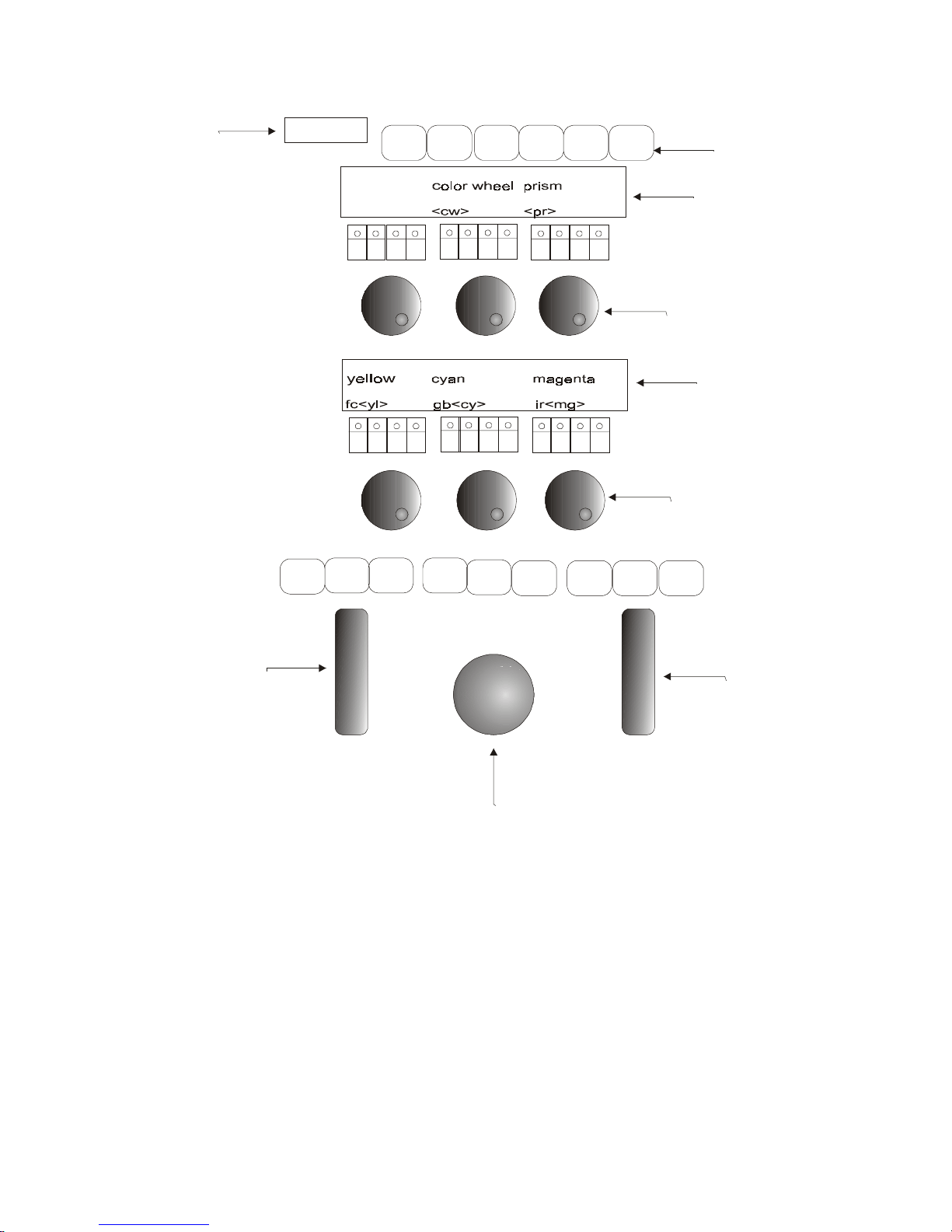
Parameter Contr ol
Sabre
2-8
1. The type of spot selected is displayed in a dedicated LED.
2. 1 wheel is dedicated to dimmer and pan assignments.
3. The wheel labeled iris always controls parameter 1 and tilt.
4. The other 6 wheels control 4 parameters each.
5. There are 6 parameter banks, arranged as I, F, C, B, and 2 additional banks.
Parameter to bank assignments can be customized in the Mix Output menu.
6. Each parameter key has an LED. The LED is on the parameter is selected.
7. A parameter that appears between brackets < > can be immediately addressed with the
wheel.
8. There is 1 sensitivity adjustable trackball for pan and tilt. The pan or tilt may be
locked.
IFCB12
DIM
X
PAR AM
RETURN
X
LOCK
Y
LOCK
FINE
TUNING
IR IS Y
FREEZE EFFE CT
EFFECT
SuperZoo
P ara m e ter w h ee ls
P ara m e ter w h ee ls
Iris/Tilt W h ee l
Dimmer/Pan Wheel
Trackball
Spot Type
W heel Bank keys
W heels LC D
display
W heels LC D
display
Page 29

Crossfaders
Sabre
2-9
Crossfaders
The A/B crossfader is the primary playback crossfader of the system. A and B each have
an LED display showing which memory is currently active and which is the next memory
in the sequence. Fades are executed according to prerecorded rates or by manual
movement of the crossfader. The automatic fade rate on the A/B crossfader can be taken
over manually with the A/B Rate Wheel.
The C/D crossfader also runs memories in numerical sequence and has LED displays,
showing which memory is currently active and which is the next memory in the sequence.
Crossfader C/D is a convenient place to run loops of memories. The automatic fade rate on
the C/D crossfader can be taken over manually with the C/D Rate Wheel.
Crossfaders A/B and C/D can be defined as split crossfaders or as a Crossfader and a Rate
fader.
Controllers
The 24 controllers accept memory, groups of spots and/or channels, and spot parameters
assignments.
They also accept memory loop, memory range assignments, and Q lis t assignments, thus
functioning as chasers. The chasers can be assigned to run in hard or soft playback mode.
Each controller has 2 assignment mode keys: [DIM] and [XF]. The assignment mode keys
double as go and Hold command keys for chasers.
Each controller also has a Bump Button.
The Joystick
The joystick takes over the x/y parameters of any spots or chasers assigned to it, giving the
operator manual control of pan and tilt.
Spots can be assigned to the joystick either directly on the keypad , via Auto Assign, or via
Event.
The Move Chase option gives the joystick control over the x/y parameters of entire chase
sequences. This allows you to reposition a chase in its entirety. There is an option to store
the new chase position.
General Master
The general master controls the overall dimmer output of the console.
The General Master fader has a blackout key, which turns off all dimmer outputs in the
system.
The level of the general master is displayed in the upper ri ght corner of display monitor 1.
Channels can be removed from General Master control. This is useful when using
scrollers and DMX devices such as smoke machines.
Page 30

Submasters
Sabre
2-10
Submasters
Submasters 1 - 3 accept chann el, spot, and memory assignments. Th e s u bm asters can al s o
be configured to submaster A/B, C/D via a switch in the System Parameters menu.
Freeing Assignments
The [FREE] key is used to free controller and submaster assignments and erase Snaps,
Libraries, G roups , Palettes, Displa y Macros, an d Effect P alettes (se e above.
You can lock [FREE] with a double hit. Any keypress releases the lock.
To free more than 1 controller assignment and submaster assignment:
Keypresses
1. Press and hold [FREE]
2. Press [DIM] or [XF] for multiple controllers
Page 31

Menus
Sabre
2-11
Menus
Menus provide tools for Patching, defining system parameters, Disk Management,
Memory Management, Macros, and other special functions.
Menu Purpose
1. Patch Create homogenous beam movement, for moving lights,
regardless of the physical orientation of the device.
2. Load Load show files from a floppy disk or from the hard disk. All of
the data contained in a show file can be loaded or selected
parts.
3. Memory Operations Rename, copy, and delete memories.
5. Record Record Sabre’s memory contents to a floppy disk or to the hard
disk.
7. Channel Patch Dimmer management includes soft patch, assigning dimmer
curves, and testing channels or dimmers. Patching for DMX
input.
8. System Parameters General system information is displayed. There are options that
you can redefine to customize the system.
9. Macro Create, modify, and delete Macros.
10. Delete Play/Act Delete show files from a floppy disk or the hard disk.
13. Scroll er Assig n control ch a nnels to scrollers, fine t une frame set ups,
enable the dark gel option. This menu does not appear if the
system is not configured for scrollers.
14. Printer Generate hard copy of show data.
17. MIDI In/Out Enable keys and controllers for MIDI communication. Edit
default MIDI codes. Program macros of MIDI command
strings. En a ble or disable the MIDI Synch function.
19. Mix Output Moving Light management includes control number patching,
assigning output addresses, customizing the Default Device
List, defining connector assignments, enabling Ethernet
communication, defining or customizing device definitions.
20. Leader Initialize spots for participation in the Leader function.
21. Event Program Events that trigger multiple playback events in the
system.
22. Device Priority Define the control priority of playback devices. Store a library
of operator defined priority maps. Change the default hierarchy
or instruct Sabre to work in LTP mode.
23. Touch Screen Define and calibrate the touch screen.
25. Autosave Manually trigger the Autosave function to save the current
memory contents in Sabre. Restore the data contained in an
Autosave file.
26. Network Settings Assig n IP addresses, ID numbers, and mappi ng the n et work
settings for Ethernet communication.
Page 32

Menus
Sabre
2-12
Accessing menus
To view the menu list, press [MENU].
Go to a menu by either pressing the appropriate F key, displayed at the bottom of the
screen or by using the sh ortcut.
Shortcut for menu access
1. Enter the number of the m enu, as it appears in the num ber ed list.
2. Press [ENTER]
Exiting the menu mode
[RESET] exits the menu mode. Press once to return to menu list. The second press
returns you to stage display.
[MENU] also exits the menu mode. Pressing this key exits the menu you are working on
and returns to stage.
You can exit the following menus without resetting the menu editor:
• Channel Patch
• Macro
• Effect
• Spot Patch
• Mix Output
• Scroller Patch
If, for example, you are busy in th e Spot Patch menu and you must temporarily exit the
menu, p ress [MENU] returning to stage display. When you want to return to the Spot
Patch menu, press [MENU]. You return to the point at which you exited.
F keys options change according to the type of task you are working on. A prompt line
guides you through the different ta sks an d functions. If you make an error entering
information F6 Restart returns you to the beginning of the command chain.
Number selections in the menu mode are entered on the numeric keypad of the console or,
in some cases, the alphanumeric keyboard.
Text is typed on an alph a numeric keyboard or usi ng the NSKs in Alpha mode.
Many of the different menus have more than 5 function options displayed on one page. To
view the next page of functions press: F6 More Function. It is generally assumed that if
you do not see the option under discussion, you will page through (using the MORE
FUNCTION key) until you see the option.
Some of the console keys can be u sed inst ead of the F k eys in the m enus:
MENU KEYPAD
Thru
[→]
Channel [CHANNEL]
Memory [MEMORY]
Store [STORE]
Next [+]
Previous [-]
Enter [Enter]
Page 33
Text & the A lphanum er ic K ey boar d
Sabre
2-13
Text & the Alphanumeric Keyboard
The text function allows typing short notes, reminders, and e-mail messages. You can add
text to macros, memories, to show files when recording to the diskette, to snaps, events,
libraries, controller group assignments, Q Lists, and even leave a note for the second shift
crew. Operating instructions for adding text to the above mention ed items are includ e d in
the sections dealing with those subjects.
Text is typed on the alphanumeric keyboard or on the Numeric soft keys in Alpha mode.
A page of text
One page is available for text typed on the alphanumeric keyboard. This is useful for
recording any notes about special rigging, color changes during interval, cue synopsis, any
special comments pertaining to the show, etc.
If the text page contains text it is the immediately displayed when the system is turned on.
This makes it a convenient place to leave notes and messages for the next shift.
Keypresses Results/Comments
1. Press the [TEXT] key
A blank blue screen is displayed. This i s the
text page.
2. Type the text on the
keyboard or on the NSKs i n
Alpha mode.
3. Press [STORE]
Erasing text
Delete any text with [ERASE].
Moving the cursor
Key What it does
Æ
Æ
Move cursor one position to the right.
Å
Å
Move cursor one position to the left.
↑
Move the cursor on e line up .
↓
Move the cursor on e line down .
Home
Move the cursor to the beginning of the text.
End
Move the cursor to t he end of the text.
Delete
Delete text from the cursor position to the end of the text.
Enter
Move the cursor to the beginning of the next line.
Backspace
Move the cursor back and clear the character .
Tab
Move the cursor 3 positions to the right.
Page 34
Text & the A lphanum er ic K ey boar d
Sabre
2-14
Using the text keyboard for editing
The text keyboard can be used for some editing functions.
Press? on the alphanumeric keyboard to view the keyboard equivalents.
A – Text o – Spot F – Frame
b – (not used) p – Part Q – Q-List
c – Channel q – Memory @ - intensity
d - Pg Dn 2 r - Rem Dim ^ - Except
e – Effect s – Store [ - +@
f – Full t – Time
] -
@
g – Mask u - Pge Up 2 Bs – CE
h – Help v - (not used) spacebar – Clear
i – Teach Macro w – Wait % - Flash
j – (not used) x – Exa m & - +Store
k – Link y – Exam 2 > -
Æ
l - Loop z – Zero Tab – Stage
m – Menu D - Delta Del – Erase
n – (not used) E – Event Esc - Reset During editing,
after inserting text to
memor ies, etc. u se ESC to
exit text mode.
The alphanumeric keyboard has a lock to prevent unintentional editing. Activate the lock
by pressing ALT A. Unlock the keyboard for editing functions by pressing ALT A again.
This lock does not affect the functioning of the alphanumeric keyboard when [TEXT] has
been selected on the console.
¾
¾
Note
To use the Print Screen function on the text keyboard, you must “unlock” the keyboard.
Page 35
Getting Help
Sabre
2-15
Getting Help
On-line help contains a short description of each of the keys and the important key
sequen ces . When the help window is op en, pressing a key on the console only di sp lays its
help and does not execute its function.
Keypresses Results/Comments
1. Press [HELP]
A window opens in the middle of the displ ay
screen.
2. Press any key you would lik e
to know more about.
A short expl anation and any relevant
keystroke sequences are displayed.
3. To exi t help, press [HELP]
¾
¾
Note
When the Help window is open the consol e k eys are disabled!
System Status
You can check the status of connected peripherals from panel. The peripherals include the
Submaster Wing, the Macro Extension Keyboard, the Remote Control, the Wire/less
Remote Control, and the alphanumeric keyboard. You are notified if the battery is getting
low.
Color key for System Status
Color What it means
Blue Device installed and functioning correctly.
Red Fault
White Not installed
What to do in case of disconnection
If a peripheral is physically disconnected or there is a communication problem a red
blinking S, appearing in the command line notifies you that there is a problem. You can
turn off the blinking S by going to the System Status window and selecting F2 Ignore.
Keypresses Results/Comm e nts
1. Press [•]
The System S tatus window opens. The
peripheral device status i s di spl ay ed.
2. Press F1 and select the device
3. Press F2 Ignore
4. Press [STAGE] or [CLEAR] to return
to the edit or .
Page 36

System Status
Sabre
2-16
Disabling a device
You can also disa bl e any device connected to the console.
Keypresses Results/Comments
1. Press [•]
The System S tatus window opens. The
peripheral device status i s di spl ay ed.
2. Press F1 and select the device
3. Press F3 Disable
Disabled
appear in red nex t to the device.
4. Press [STAGE] or [CLEAR] to return
to the edit or .
¾
¾
Note
When the alphanumeric keyboard is locked it is designated as Disabled in the System
Status window.
If the S u bm aster Wing is disconnected from the console, th e output fr om the Wing is
moved to the editor and the Status error message blinks in the command line. The
assignments to the Submaster Wing are retained. If you reconnect the Submaster Wing,
the situation is the same as prior to the disconnect. However, if you go to the System
Status window and tell the console to ignore or disable the Submaster Wing, all of the
assignments on the Wing are released.
Page 37

CHAPTER 3
DISPLAYS
This chapter includes:
Display contr ol
Display Formats
Messages and commands
Stage display
Playback Display
X-fade Exam
Exam displays
Display Macros
Programming a Display Macro
Adding text to a Display Macro
Using Displ a y Macros
Deleting a Display Macro
TOPO
Positioning spots on the TOPO map
Relocating a spot on the TOPO map
Removing a spot from t he TOPO map
Examining active parameter values
Page 38

Display Control
Sabre
3-2
Display Control
Monitor 1 and monitor 2 have separate controls. If your system has the optional third
monitor, use the [SHIFT] and the controls for monitor 1.
One of the monitors can be a Touch Screen. The NSKs and menus can be controlled using
the Touch Scr een.
The system uses full color VGA displays. Spots, spot parameters, and channels a re color
coded according to where their output origin: the controllers, A/B, C/D, the editor, or
DMX input .
The display on monitor 1 is divided into 4 windows. The cursor (a white rectangle in the
left corner of a win dow) indicates the window th at will respond to paging commands.
The keys [DOWN 1/3], [UP 1/3], [DOWN 2], [UP 2] go to the next or pr evious page of
the display area containing the cursor.
Example: You want to view the second page of channels on monitor 1.
Keypresses
1. Press [WINDOW] unti l the cursor is locat ed in the upper lef t corner of the
channel display .
2. Press [UP 1]. The next page of channels is now displayed.
Press [DOWN 1]. The previous page of channels is now displayed.
Display Formats
[STAGE] toggles the display, on monitor 1, between the stage display and the x-fade
exam display.
Monitor 1 provides 2 displays:
• Stage display showing spots, channels, and playback.
• X-fade Exam display showing the memory sequence on the crossfaders and controller
assignments and status.
[TOPO] switches the displays on monitor 2.
There are 3 displays available on monitor 2:
• A small TOPO display and Sta g e di sp l ay with 2 4 sp ots.
• A full screen TOPO display
• Stage display with a full-screen channel display
You can switch between monitor 1 and monitor 2 by pressing [SWAP SCREENS].
Print Screen, on the alphanumeric keyboard, generates hard copy of monitor 1. To print
display on monitor 2, swap between the monitors.
[SHIFT] [ST AGE] toggles the displays on monitor 3.
Monitor 3 offers 2 types of Stage displays:
• Stage display showing 24 spots
• Stage display with a full-screen channel display
Page 39

Display Formats
Sabre
3-3
Messages and commands
The area at the top of the screen is reserved for:
• Messages
• Submaster Assi g nments
• Blind Mode Flag
• Autosave flag and progress bar
• Teach Macro Flag
• MIDI status
• MIDI synch status
• Gran d Ma ster level
The line at the bottom of the screen houses:
• The command line - the command line echoes the keypresses and contains up to 44
characters.
• The clock
• Delta flag
• The current Q List
• The last memory recorded or called into the editor.
Stage display
The spot display area
The Spot Display is located in th e upper half of the Stage Display screen. The Stage
display shows up to 192 spots with 24 spots per page.
The default display is:
Monitor 1 spots 1 - 24
Monitor 2 spots 25 - 48.
Each spot is shown as a vertical column. The parameter numbers and names are displayed
at the side of the column.
You can display any of the pages on either monitor by paging. If monitor 3 is present, its
Spot display default is from spot 49 – 72.
Parameters
Spot parameter values are displayed as numerical values in the spot number column. The
color of the parameter value displayed depends on the output source of the data; whether it
derives from A/B, C / D, controller s, a chaser , the editor, trackin g , a library, or DMX Input.
X and Y (pan and tilt) display the coordinates of the spot's mirror.
Dim is the level of the unit's dimmer.
The “p” numbers represent the spot parameters as defined in the Mix Output menu.
Examples of possible parameters:
• ir - iris
• mg - magenta
• gb - g obo position
• vl - velocity. The speed at which the mirror moves
• cw - color wheel
The parameter names are displayed on the Stage display and on the LED Wheels display.
Intellabeam and Cyberlight special parameter modes are represented by icons.
Page 40

Display Formats
Sabre
3-4
Jump display
You can set the system so the displays jump to display the highest spot number selected on
monitors that are displaying spots.
Example: Spots 1 – 24 are displayed on monitor 1. Spots 25 – 48 are displayed on monitor
2. Select spot 72. Monitor 2 jumps to the page containing spot 72.
The Auto Jump option in the System Parameters menu controls this function. (See Chapter
26 System Configuration for information on the user definable options in the System
Parameters menu.)
The Jump Display has a number of settings:
F1 No Jump - Disabled
F2 Auto – Spot display jumps where convenient.
Example 1: Monitor 1 shows the Stage display (spots 1 – 24), monitor 2 sh ows the
full-screen T OPO d i sp l ay, and monitor 3 shows the Memory Exam. Select spot 45.
Monitor 1 jumps to the page displayin g spot 45.
Example 2: Monitor 1 shows the Stage display (spots 1 – 24), monitor 2 sh ows the
full-screen T OPO d i sp l ay, and monitor 3 shows spots 25 - 48. Sel ect sp ot 1 0 and 50.
Monitor 3 jumps to the page displayin g spot 50.
F3 Monitor 1 – Spot display jumps on monitor 1 only,
F4 Monitor 2 – Spot display jumps on monitor 2 only,
F5 Monitor 3 – Spot display jumps on monitor 3 only,
Channels
Channel information is displayed in the lower left quarter of the Stage display on monitor
1, showing 40 channels, or a full-screen display on monitors 1 and 3, showing 220
channels.
Scrollers that have been patched to control channels (see Chapter 28 – Channel and
Scroller Patching) are displayed with the channel information. Channels that also control
scrollers are displayed with an ‘s’ and the frame number is displayed under the intensity
level. Scroller frames track through the show.
The Playback display
The lower right quadrant of the Stage display is reserved for playback information. There
is a graphic representation of the A/B and C/D crossfaders, showing:
• Outgoing memory
• Incoming memory with 5 text characters
• The time of the incoming memory
• Fade Rate information
• Control priority information
• Loop information, if pertinent
• Auto Assignm ent flag
• Sequence direction – for C/D only
The Controller area of the Playback display is located beneath the crossfader display.
If the assignment is a Memory, the memory number is shown next to the controller
number.
If the assignment is a Group of lights (whether channels or spots), grp is displayed next to
the appropriate controller number.
Page 41

Display Formats
Sabre
3-5
If the assignment is a Spot Parameter, the spot type and parameter name is displayed.
Each assignment is flagged as Dim or XF.
The Q-Key status is shown in the Playback display. When the [PILE ON] key (Q-Key
playback mode) is active
Qkey
is dis p layed. When the [PILE ON] key is not active
Qkey
is displayed.
The LTP (Latest Takes Precedence) flag is displayed h ere. LTP displayed in red, means
that th e control p riority for playback devices is on a Latest Takes Precedence basis. LTP
displayed in gray means that the current playback control priorities are valid until the LTP
function is turned on again.
The X-Fade Exam display
This display shows a short memory list of the next few memories sequencing on the A/B
crossfader. T he number of memories displayed here depends on how many Auto Assigns
and P art Qs are pr es ent.
Bar graph representations of the playback crossfaders dynamically display the progress of
a crossfade.
C/D crossfader assignments appear in the upper right corner of this displa y. A bar graph
dynamically displays the progress of a crossfade.
The Controller/Chaser display
The controller/chaser display on the X-fade exam includes the type of assignment, the
controller level, and priority information.
For chaser assignments the assigned memory range, Q-List origin, chaser mode, and
priority information is displayed. The display is dynamic when the chaser is running.
A roll up parameter assignment shows the moving light type and the assignment
parameter. A roll up assignment allows you to address the assigned parameter, by raising
or lowering the controller, crossfading from its current output to Full.
Displaying control priority
When working in LTP control priority mode, it is important to know the order of the
priority stack since the priority stack is fluid and changes with each playback operation,
assignment, or bump to first priority. This information is shown in the controller area of
the X-fade Exam display.
Page 42

Exam Displays
Sabre
3-6
Exam Displays
There are many different exam displays. Exam displays furnish a great deal of
information. Some exam displays are list, such as a list of memories or snaps. Some exam
displays allow you to view all the details of selected item, such as a memory.
There are 2 basic types of Exam displays. Strong displays and weak displays. Weak
displays are cleared by any keypress. Strong displays remain on the screen and you can
continue to work keeping the display on view. An example of a weak display is Free
Channels. An example of a strong display is: Memory List
Exam What is shows
Free Spots Exam A list of spots not used in any memories.
Selected Spot Exam Th e memories in which the spot appears and parameter
values, Libraries, and Effects in each memory.
Free Channels Exam A list of the channels not used in any memory.
Selected Channel Exam The memories in which the channel appears, intensity,
frame, and Effect assignments.
Memory (Cue) List A sequential list of all recorded memories, including loop,
link, fade time information, text, and Event assignments.
Specific Memory Exam Values, Libraries, Effects, and Part assignments are
displayed for all channels and spots in the selected memory.
Library List A list of the recorded Libraries, including any text.
Specific Library Exam The spots and the parameter values in the selected library.
Library Track Sheet A list of memories and the spots in each memory that have
the library assignment.
Snap List A list of the Snaps and text.
Specific Snap The playback device assignments and playback modes or
status recorded in the Snap.
Effect Palettes A list of Effect Palettes.
Selected Effect Th e E ffect s assign ed to each pa ramet er are d isplayed.
Palettes The list of Palettes.
Selected Palette The ID number, spot type and parameter values are shown
Group List The list of Groups.
Selected G roup The cont ents of the selected Group.
Events The Event list, including assigned SMPTE time codes.
Contr oll er Assignments Information pertaining to the assignment on selected
controllers.
Q-Key Assignment s The Q key assignment, showing the memory number a nd the
contents of the memory
Sequences for accessing the exam displays are contained in the discussion of the different
functions.
Page 43
Display Macros
Sabre
3-7
Display Macros
The NSK mode Displ ay allows you to create and save Display set-ups. The Display mode
functions like Macros containing display configurations that include all of the monitors
and the LCD displays. Display Macros can be activated at any time with out interfering
with your current operational sequence.
You can save any display configuration. Example: monitor 1 shows spots 1 – 24 and page
4 in the Channel window, monitor 2 shows spots 49 – 72, monitor 3 shows the Memory
List, and the Controller’s LCD display is set to assignments and text.
The Display macro Saves the display status, but not the contents. Example: A Display
Macro was saved with t he Memory List on monit or 2 . When the Display Macro was saved,
the default QList was QList 5, so the Memory List showed the memories in QList 5. If you
use this Display Macro when the default is QList 10, the Memory List shows the memories
in QList 10.
The spot and channel page is saved in the Display Macro. The mode of the library display
(parameter values or library numbers) is also stored.
All or some of the display elements can be saved in the Display Macro. Pressing
[ASSIGN] in Display mode opens a win dow showing the display elements.
1. Press an F key to exc lude the associated elem ent from the Display Macro.
The excluded element i s di spl ay ed in gray.
The default is to include all the display elements. If you change the default Sabre
remembers and saves your preference.
The NSK Exa m in Displ a y mode shows the key num ber , the displa y elements status, and
text labels.
Programming a Display Macro
Exampl e: St ore Display Macro 9 using the NSKs.
Keypresses Results/Comments
1. Set up the displ ay on y our
monit or s.
2. Press [ASSIGN]
3. Press [DISPLAY]
Skip this step if the NSK mode is Display.
4. Press NSK [09]
The message
Display 9 Stored
is displayed.
The LED for NS K 09 is lit.
F1 F2 F3 F4
CRT 1
CRT 2
CRT 3 LCDs
Page 44

Display Macros
Sabre
3-8
Example: Program Display 9 using the numeric keypad.
Keypresses Results/Comments
1. Press [DISPLAY]
Display
is displayed i n the command l ine.
2. Enter 9 on the keypad.
3. Press [STORE]
The message
Display 9 Stored
is displayed.
The LED for NS K 09 is lit.
Adding text to a Display Macro
Keypresses Results/Comments
1. Press [DISPLAY]
2. Press [TEXT]
3. Enter the di spl ay number on
the keypad.
4. Type the text on the keyboard
or use the NSKs in the Alpha
mode.
The text appears in the command line.
5. Press [STORE]
The message
Display # Stored
is displayed.
Using Display Macros
Example: Operate Display macro 25
Keypresses Results/Comments
1. Press [DISPLAY]
Display
appears in the com mand line.
2. Enter 25 on the keypad
3. Press [ENTER] The monitor displays and LCD displays change
according to the set up in the Display macro.
Or
Keypresses Results/Comments
1. Press [DISPLAY]
Skip this step if the NSK mode is Snap.
2. Press [NSK 25] The monitor display s and LCD di spl ay s change
according to the set up in the Display macro.
Page 45

TOPO
Sabre
3-9
Deleting a Display Macro
Example: Delete Display macro 25.
Keypresses Results/Comments
1. Press [DISPLAY]
Display
appears in the command line.
2. Enter 25 on the keypad
3. Press[ ERASE]
Sabre asks
Are You Sure?
4. Press [ERASE] again.
The message
Display(s) Erased
is displayed.
Or
Keypresses Results/Comments
1. Press [FREE]
2. Press [DISPLAY]
Skip this step if the NSK mode is Display.
3. Press [NSK 25]
The message
Are You Sure?
is displayed.
4. Press [NSK 25]
The message
Display(s) Deleted
is displayed.
TOPO
You can create a topographical map of the moving lights in your rig. The lower portion of
monitor 2 d i sp l a ys a portion the T OPO m a p a t all times. Use the trackball to scroll the
map up or down. The editor m u st be in idle to scroll t he TOPO map.
Constr uct i ng the TOPO map is done on t he full screen T OPO display on monitor 2 . Each
spot positioned on the map is represented by a blue square containing the spot number and
label.
Positioning spots on the TOPO map
Keypresses Results/Comments
1. Select t he spot for
positioni ng.
2. Press [TOPO]
The full screen TOPO map is displayed on
monit or 2. There is a red square in the l ower
left corner. This represents the selec ted spot.
3. Use the TB (track ball) to
position the r ed square.
4. Press [STORE]
The red square turns blue and di spl ay s the
number and label of the spot. Use [+] or [-] or
enter a number on the keypad to choose the
next spot number for positioning on the map.
5. Repeat steps 3 and 4.
Page 46

TOPO
Sabre
3-10
Relocating a spot on the TOPO map
Keypresses Results/Comments
1. Select t he spot y ou want t o
relocate.
2. Press [TOPO]
The selected spot flashes on the TOPO map.
3. Use the trackball to reposition
the spot.
4. Press [STORE]
The spot is dropped in its new location.
Removing a spot from the TOPO map
Keypresses Results/Comments
1. Select t he number of the spot
you want to remove.
2. Press [TOPO]
View the full screen TOPO display.
3. Press [ERASE]
The selected spot i s erased from the map.
Color key for TOPO display
Color What it means
Red Spots selected in the editor.
White Spots present in the editor.
Yellow Spot output from controllers.
Page 47

CHAPTER 4
QUICK START
This chapter includes:
Setting up Sabre
Configuring Sabre
Patching
Patching spots
Patching channels
Patching Scrollers
Programming a memory
Playing back a memory
Playing back chasers
Page 48

Setting Up Sabre
Sabre
4-2
This chapter contains very brief explanations of Sabre’s basic functions. It is intended for
experienced operators, operators familiar with the Compulite consoles, or just plain
impatient operators.
Setting Up Sabre
1. Connect the alphanumeric keyboard and the monitors to the appropriate ports on the
back pane l.
2. Connect t he DMX and (if present) S-Mix leads to the output ports.
3. Plug the power cable into a power source.
4. Press and hold the [CE] and [CLEAR] keys wh ile switching on the console.
5. Release the [CE] and [CLEAR] keys. Sabre goes through its boot up p rocess and
finally displays the main Service Tools menu.
6. The next step is config u ring Sabre.
Configuring Sabre
You must tell Sabre how many moving lights, dimmers and channels, and scrollers you
are running. The instructions below treat this subject at its simplest level.
1. Looking at the main Service Tools menu, press F3 Config System.
2. Enter the number of spots, “big” spots; enter the first spot number for big spots,
number of channels, dimmers, and scrollers that you will be running.
3. Press F6 Enter & exit.
4. Press F6 Store configuration.
5. Switch off Sabre.
6. Switch on Sabr e.
7. When the main Service Tools menu is displayed, press F1 Cold Start.
For more information see Chapter 26 System Configuration.
Page 49

Patching
Sabre
4-3
Patching
Patching should be done before recording any memories.
Sabre ha s 4 Patch menu s:
• Mix Output menu (menu 19) - Moving light m anagement; patch devices to spot
numbers, assign DMX outp ut addresses, a nd define moving d evices.
• Patch (menu 1) - Flips and exchanges the x and y axes of the mirror movement to
create homogeneous beam movement.
• Channel Patch (menu 7) - Soft patch dimmers to channels, assign dimmer curves,
enable/disable General Master control, and more.
• Scroller Patch (menu 13) - Patch scrollers to control chan nels, determine dark gel
assignments, fine tune gel string placement.
All of the menus have easy to follow prompts that guide you through the various functions.
Patching and addressing moving lights
1. Go the Mix Out pu t menu.
2. Select the type of moving light you are using from the Device List. If it does not
appear in the device list check the Device Pool. If it appears in the Device Pool, copy
the device definition to the Device List. If the moving you are using does not appear
in the Device Lis t or th e D evi ce P ool, you can define it yourself. When you define a
device yourself, consult the manufacturer’s specifications.
3. Assign spot numbers to th e selected device.
4. Assign Out p u t Ad dresses to the spot nu m ber s.
5. Exit the Mix Output menu.
See Chapter 27 - Spot Management, for furthe r inf ormation.
Page 50

Patching
Sabre
4-4
Creating homogeneous beam movement
1. Go to the Spot Patch menu.
2. Press F1 Patch Position.
3. Select the spot you want to adjust.
4. Press F1 Co nvert To. The dimmer of the selected spot is turned on.
5. Select one of the movement options (1-8) by en t eri ng the number on the num eri c
keypad. You can use the trackball to check your selection.
6. Press F1 St ore Convert.
See Chapter 27 - Spot Management, for furthe r inf ormation.
Patching dimmers to channels
1. Go to the Channel Patch menu.
2. Press F1 Assign Dimmer.
3. Enter a dimmer number in answer to the prompt.
4. Press F3 To Channel.
5. Enter a channel number in answer to the prompt.
6. Press F1 Store.
See Chapter 28 - Channel and Scroller Patching, for further information.
Patching scrollers to channels
The scroller to channel default patch is 1-to-1. This is easily changed in the Scroller Patch
menu.
1. Go to the Scroller Patch menu.
2. Select a scroller by entering the scroller number on the numeric keypad.
3. Press F2 To Channel.
4. Enter the channel number in answer to the prompt.
5. Press F1 Store.
See Chapter 28 - Channel and Scroller Patching, for further information.
Page 51

Programming Memories
Sabre
4-5
Programming Memories
Spots, channels, and scrollers can all be included in the same memory.
1. Select spots usin g t he NSKs in Spot mode or use t he numer i c keypad.
2. Assign pa rameter values. Use the par a m et er wheels or press a p a rameter k ey and
assign a value on the numeric keypad. (Use [STEP UP] and [STEP DOWN] for
discrete and mixed step parameters).
3. Select channels using the numeric keypad.
4. Assign i ntensity usin g t he dimmer wheel or press [@] and assign an intensity value
using the numeric keypad.
5. Select a scroller channel.
6. Assign a scroller fram e usi ng the iris wheel or pr ess [FRAME] and assign the frame
using the numeric keypad.
7. Press [MEMORY] or press [=].
8. Enter the memory number using the numeric keypad.
9. Make fade time assignments by selecting the time in, time out, wait in, wait out, or
delay and entering the time assignment on the numeric keypad. Press [TIME] for
time in. Press [TIME] [TIME] for time out. Press [WAIT] for delay. Press [WAIT]
[WAIT] for wait in. Press [WAIT] [WAIT] [WAIT] for wait out.
10. Press STORE.
11. Press RESET to clear the editor. You can also continue programming the next
memory using the spots and channels that remain in the editor after STORE was
pressed.
See Chapter 7 - Programming Memories, for further information.
Playback Memories on A/B
1. Select a memory by pressing [MEMORY] and the memory number.
2. Press A or B. It is recommended to assign the memory to the inactive fader; if the
fader is at A assign the memory to B, if the fader is at B assign the memory to A.
3. Move the fader so the memory is active on stage.
4. Press [SEQ]. The next memory is now on board.
5. Press [GO] to begin the crossfade from the active memory to the memory on board.
See Chapter 12 - The A/B Crossfader, for further information.
Page 52

Playback chasers
Sabre
4-
6
Playback chasers
Cha s ers are played back on the cont roller s .
1. Select a range of memories. If the first memory has a loop assignment, you select the
first memory only.
2. Select t he chas er playback m od e by pr ess ing [HARD] or [SOFT ].
3. Press th e [GO DIM] or [HOLD X-FADE] key for one of the controllers. The LEDs
on bot h of the keys blink.
4. Press [GO DIM] to start the chaser.
See Chapter 13 – Controllers, Submasters, and Joystick for further information.
Page 53

CHAPTER 5
SELECTING AND EDITING
SPOTS
The subjects included in this chapter are:
Igniting spots
Igniting DMX spots
Igniting S-Mix or L-Mix spots
Ignition exam
Selecting spots
Changing the number default selection
Selecting spots using the numeric keypad
Selecting more than one spot
Selecting sp ots u si ng the Numeric Soft Keys
Canceli ng a selection using NSKs
Recalling the last selection
Selecting spots in the editor and on stage
Mix editing of spots
Spot Parameters
Parameter wheels
Trackball
Assigni ng values to pan a nd tilt
Assigni ng dimmer values
Selecting parameters and assigning values
Returning to home values
Copying parameter values
Releasing Spots/Parameters from the Editor
Releasing a spot from the editor
Releasing a parameter from the editor
Page 54

Igniting Spots
Sabre
5-2
Igniting Spots
Most moving devices have a control channel for functions such as igniting the lamp,
extinguishing the lamp, resetting the device, and fan control.
This control channel is known as Ignite and is included in the device definition. The
ignition sequences depend on what function you are requesting and on the ignition
channel’s definition.
Igniting DMX spots
Sending the default value
Keypresses Results/Comm ents
1. Select spots.
2. Press [IGNITE]
3. Press [ENTER] The default value as defined in the device
definition is transmitted. The duration of the
transmission depends on the time as defined in
the device definition.
Sending a value other than the default value
Example: To send a Reset command to a Studio Color device, send the value 64.
Keypresses Results/Comments
1. Select spots.
2. Press [IGNITE]
3. Enter 64 on the numeric
keypad.
4. Press [ENTER]
The Reset command is transmit ted to the
device.
For more information on defining the ignition control, see Chapter 26 Spot Management.
Page 55

Igniting Spots
Sabre
5-3
Igniting S-Mix or L-Mix spots
The ignition channel definition for S-Mix and L-Mix spots is factory configured and may
not be changed.
Ignition values for Intellabeam and Cyberlight
Reset and turn on the lamp:
Keypresses Results/Comm ents
1. Select spots.
2. Press [IGNITE] [1]
The dev ice resets itself and the lamp is
struck.
Turn off the lamp:
Keypresses Results/Comm ents
1. Select spots.
2. Press [IGNITE] [0]
The lam p is extinguished.
Ignition values for Coemar NATs
Strike the l amp:
Keypresses Results/Comments
1. Select spots.
2. Press [IGNITE] [1]
The lamp is struck
Reset the device
Keypresses Results/Comments
1. Select spots.
2. Press [IGNITE] [2]
The dev ice resets itself .
Extinguish the lamp
Keypresses Results/Comm e nts
1. Select spots.
2. Press [IGNITE] [0]
The lam p is extinguished.
Page 56

Igniting Spots
Sabre
5-4
Ignition exam
The Ignition Exam display shows the ignition status of the spots.
Spots that have had an ignition sequence applied are displayed with the ignition value.
Keypresses Results/Comments
1. Press [IGNITE]
2. Press [EXAM 1] or [EXAM 2]
The Ignit e E xam is display ed.
3. Press [UP 1] or [UP 2] to
view the next page.
Color key for Ignition Exam table:
Type Color
DMX
gray
DMX with discrete step
ignition
blue
S-Mix
yellow
Page 57

Selecting Spots
Sabre
5-5
Selecting Spots
Use the numeric keypad or the Numeric Soft keys in Spot mode to select spots.
Selected spots appear in red on the Stage display. All parameter value assignments are
carried out on spots appearing in red.
The parameter names of the selected spot/s are shown on the Stage display and th ey also
app e ar i n the LCD d isplays above the pa ram e ter s election keys. If you are work ing in t he
Mix Editing mode (see System parameters menu) the parameter selections are shown for
the last type of spots selected.
Groups can also be used for spot selection .
¾¾Note
The direction of the selection is remembered. This is especially important when
programming Effects. When the spot selection is 1 Æ 12, spot 1 is the leading spot in the
Effect. When the spot selection is 1 2 Æ 1, spot 12 is the leading spot in the Effect.
Changing the number default selection
When the number default selection is spot, the first number you press is recognized as a
spot selection. The number default selection can also be Channel or Memory.
Keypresses Results/Comments
1. Hit [SPOT] twice.
Spot
appears on a gray fi eld in the command line.
Selecting spots using the numeric keypad
When a spot number is selected, all the parameter names and numbers appear on the Stage
display. The spot/s selected appears in the command line after Spot.
Keypresses Results/Comm e nts
1. Press [SPOT]
Skip this step if the default number sel ec tion is
Spot.
2. Enter the desired spot
number on the numeric
keypad.
The paramet er names of the selected spot/s
appear on the Stage di spl ay . They also appear in
the LCD wheels’ displays above the parameter
selection keys.
Selecting more than one spot
There are several series of keystrokes to select one or more than one spot at a time. These
keystrokes may be combined in any way lending great versatility to spot selection.
[SPOT #] Select a si ngle spot.
[SPOT #] [SPOT #] [SPOT #]
...
(SPOT, functi on s a s a n "and" key) Select a group of
spots.
[SPOT] [#
Æ
Æ
#] Select a range of spots.
[SPOT #
Æ
Æ
#] [EXCEPT #] Select all the spots in the range, excluding the designated
spot.
Page 58

Selecting Spots
Sabre
5-6
Any permutations of spot selection may be used.
For example:
[1
Æ
Æ
3] [SPOT 8] [SPOT 10] [SPOT] [22
Æ
Æ
30] [EXCEPT] [SPOT 25].
These possibilities make spot selection very flexible.
You can also program Groups for one press selection of frequently used groups of spots.
See Chapter 17 Groups.
Selecting spots using the Numeric Soft Keys
A double hit on [SPOT] NSK mode sets the Num eric Soft keys for spot selection. Spot
appears in the mode display window and is marked in red on the Numeric Soft Key
display.
To view the NSK displa y press [EXAM] [51-100].
All spots are available on the NSKs. [UP] and [DOWN] increment or decrem ent the
NSKs by 100. Example: Th e NSKs sta rt from 1. Pr ess [UP] the fir st NSK i s 101. T he
NSKs start at 51. Press [UP] th e fir st NSK i s 151.
Selected spots are displayed in red on the Stage display and in the command line.
¾
¾
Note
When di scussi ng the Num eric Soft Keys [SPOT] refers to the NSK mode key.
Example: Select spots 13, 20, and 93.
Keypresses Results/Comments
1. Press NSK mode key
[SPOT] twice.
Skip this step if the NSK mode is Spot.
2. Press NSK 13 and NSK 20 The LE Ds of the selected keys are lit. The
selected spots are displayed in red
(selected) on the spot display.
3. Press [51 – 100]
Access the second page of numeric sof t
keys (numbers 51 - 100).
4. Press NSK 93 The paramet er names appear in the LCD
wheels’ displays.
Selecting a range of spots using the Numeric Soft Keys
There as an additional “thru” key (→) located in the Numeric Soft key mode area. It is
used for range selections on the Numeric Soft keys.
Example: Select spots 12 - 18.
Keypresses Results/Comments
1. Press [SPOT]
Skip this step if the NSK mode is Spot.
2. Press NSK 12 Spot 12 is display ed in red on the stage
display.
3. Press [→]
4. Press NSK 18 All spots from 12 to 18 are select ed in the
editor (displayed in red) and can be assigned
parameter values.
Page 59

Selecting Spots
Sabre
5-7
Or
Keypresses Results/Comments
1. Press [SPOT]
Skip this step If the NSK mode is Spot.
2. Press NSK 12 and NSK 18
simultaneously.
Canceling a selection using NSKs
Example: Spots 12 Æ 18 are selected. Cancel the sel ection for s p ot s 1 6 .
Keypresses Results/Comments
1. Press [SPOT]
Skip this step If the NSK mode is Spot.
2. Press NSK 16 The NSK 16 LED is extinguished.
Example: Spots 12 Æ 18 are selected. Cancel the sel ection for s p ot s 1 3 Æ 16.
Keypresses Results/Comments
1. Press NSK mode key
[SPOT] twice.
Skip this step if the NSK mode is Spot.
2. Simultaneously press NSK
13 and NSK 16
The selecti on is canceled. Their NS K LE Ds
are extinguished.
Recalling the last selection
For editing speed Sabre offers a sequence that reselects the last of group of channels
and/or spots that were active in the editor.
Keypresses Results/Comments
1. Press [SPOT]
2. Press [•]
Spots that were selected previous to the
last press on [RESET] are selected and
appear in red. T hey c an now be edited as
usual.
Selecting spots in the editor and on stage
The are some specialized spot selection key sequences that allow you to grab spots that are
in the editor and “on stage” (their output derives from a playback device).
In the examples below, spots 1, 5, 8, and 20 are present in the editor.
• [SPOT] [5 → → 8]
Select sp ot s 5 and 8. If there are sp ot s within the selected range, whose output
originates from A/B or the controllers they are also selected when using this sequence.
• [SPOT] [→] [→]
Select all of the spots present in the editor and spots whose output originates from A/B
or the controllers. The command line displays: spot from editor & stage.
Page 60

Mix Editing of Spots
Sabre
5-8
This selection tool is useful when universally modifying all of the spots contained in a
memory. Example: You want to add 10% to all of the intensity assignments in memory
1. Press: [MEMO RY 1] [SPOT → →] [dimmer wheel ]
• [SPOT 5] [→] →]
Select spots 5, 8, and 20. If there are spots, from spot 5 and up, whose output
originates from A/B or the controllers they are also selected when using this sequence.
The command line displays: spot from editor & stage.
• [SPOT 1] [→]
Selects all of the spots (from spot 1 to the last spot) in the system.
• [SPOT] [5 → 8]
Select all of the spots included in the range.
Mix Editing of Spots
The Mix Editing of Spots option appears in the System Parameters menu (see Chapter 26
System Configuration). This determines whether spots of different types are included
when a range of spots is selected or if only one type of spot in the selected range will be
addressed in the editor.
If the Mix Editing of Spots option is active and you select a range of spots, the entire
selection is addressable in the editor. If, however, the Mix Editing of Spots option is 'off',
only one type of spot is selected. The type of selected spot is determined by the last
selection in the range.
Example: Spots 1Æ 4 are Intellabeams, spots 5Æ 8 are Martins, and spots 9 Æ16 are
Goldenscans. If the mix edit option is 'on' and you select spots 1Æ12 all the spots are
selected in the editor. If the mix edit option is 'off', however, only the Goldenscans (9 -16)
will be selected. If the range selection was 1Æ 8, only the Martins will be selected.
Spot Parameters
Each parameter has a name and a number. Once you have selected a spot, a group of
spots, or a range of spots, the parameter names appear next to the parameter numbers in
the spot display.
Parameters are assigned values using either the parameter wheel or selecting a parameter
and assigning a value on the keypad or using the numeric soft keys.
There are 3 types of parameters: continuous parameters, discrete step parameters, and
mixed step parameters.
Certain parameters of Intellabeam and Cyberlight work in more than one mode (such as a
color wheel which can have a half color, rotation, etc.). An additional icon displayed after
the parameter value represents modes.
Parameter wheels
The wheels operate in a 'non-collapsing' mode, meaning that the relative difference of the
values between different spot parameters is preserved when the spots are faded up or
down.
For example, the editor contains spot 1 at 75% intensity and spot 2 at 85%. Select both of
the spots (channels) and begin to wheel up. Spot 2 reaches full intensity when spot 1 is at
Page 61

Spot Parameters
Sabre
5-9
90%. If you continuing moving the wheel until spot 1 is at FL and then you fade both
spots down, spot 1 will begin the fade first. The 10% difference in the spots' intensities is
always maintained.
Th e above exa mple u ses the dimmer parameter, however the explanation is valid for all
the parameters.
Sabre has 8 parameter wheels. The wheel labeled “Dimmer” is used for the dimmer
parameter or pan. The wheel labeled “Iris” is reserved for the iris attribute and tilt.
6 wheels control all other parameters. Each wheel controls the 4 parameters mapped to the
wheel.
The 4 parameter keys associated with each parameter wheel are used to select parameters.
Th e paramet e r names a ppear on the LC D display above t he Pa ram e ter k eys (P keys). The
active parameter is enclosed in brackets. It is not necessary to reselect a parameter
enclosed in brackets in order to access it using the wheel. To access a different parameter,
press its key.
Parameters are also assigned to banks. There are 6 banks: I, F, C, B, 1, 2. You can change
the parameter to bank assignments, by reprogramming the assignments under the Mix
Outpu t menu/Select Device/Bank Setup.
Wheel resolution can be globally adjusted. See below – Trackball and wheel resolution.
Trackball
The trackball controls position.
The X-axis is the left/right movement and the Y-axis is the up/down movement. Pressing
[X LOCK] or [Y LOCK] limits the trackball to the selected axis.
Trackball resolution
The Wheels and Trackball Resolution switch, for 16-bit parameters, in th e System
Parameters menu controls the sensitivity of the wheels and trackball.
Resolution Setting How it affects the trackball and wheels
Sensitivity 0 Exp (exponential) this is a dynamic mode. The mirror reacts
according to the speed you are moving the trackball. If you are
moving the trackball slowly, the resolution is very fine; a lot of
trackball movement results in small increments to the mirror
position. If you move the trackball quickly, th e resolution is
coarser and the mirror moves in larger increments.
Resolution 1 16 bit parameters operate in regular 8-bit resolution.
Resolution 2 Medium resolution.
Resolution 3 Highest resolution. Parameter wheels control the lease significant
bit for 16-bit resolution.
[FINE-TUNING] toggles between the resolution selected in the System Parameters menu
and extremely fine resolution. When this key is enabled (Led on) the wheels and trackballs
controlling pan and tilt increment the mirror position bit by bit.
Page 62

Spot Parameters
Sabre
5-10
Assigning values to pan and tilt
Keypresses Results/Comments
1. Select spots The parameter names are displ ay ed on the
Stage display and the wheels’ LCD display.
2. Move the T r ac k ball. X and Y are selected. T he par ameter
values are displayed in white.
Or
Keypresses Results/Comments
1. Select spots. The par ameter names are displ ay ed on the
Stage display and the wheels’ LCD display.
2. Press [X] or [Y]
X (pan) or Y (tilt) is displayed on a red field.
3. Enter a value on the keypad.
Or
Keypresses Results/Comments
1. Select spots. The par ameter names are displ ay ed on the
Stage display and the wheels’ LCD display.
2. Press [X] or [Y] Skip this step if [X] or [Y] is already active
(LED on)
3. Use the Dimmer /X wheel to
assign pan val ue.
Use the Iris/Y wheel t o assign
tilt value.
Assigning dimmer values
Keypresses Results/Comments
1. Select spots. The par ameter names are displ ay ed on the
Stage display and the wheels’ LCD display.
2. Press [DIM] S k ip this step if [DIM] i s active (LED on)
3. Use the dimmer wheel to
assign a val ue.
The dim mer value is displayed in whit e on
the Stage displ ay .
Page 63

Spot Parameters
Sabre
5-11
Or
Keypresses Results/Comments
1. Select spots. The param eter names are displayed on
the Stage displ ay and the wheels’ LCD
display.
2. Press [DIM]
3. Assign a value on t he k ey pad.
Or
Keypresses Results/Comments
1. Select spots. The par ameter names are displ ay ed on the
Stage display and the wheels’ LCD display.
2. Press [DIM]
3. Press [FULL]
The dim mer is 100%.
Selecting parameters and assigning values
Pre s s a P (para meter) key, locat e d above the whee ls, t o s e lect a n individual parame ter. Th e
active wheel assignment appears in brackets on the wheels' LCD display.
The active parameter default depends on the selected wheel bank. .
Wheel Bank Default selections
I (intensity) [DIM] and [IRIS]
F (focus) [X] and [Y]
C (color) C olor parameters
[DIM] and [IRIS]
B (beam) Gobo and other beam shapi ng
parameters
[DIM] and [IRIS]
Selected parameters appear in dark red on the spot display an d th e parameter key LED
blinks. Parameters that are present in the editor (parameters that were previously
addressed) appear in light red on the spot display and th e parameter key LED is lit.
After selecting a parameter you can assign a value using the wheel, [STEP UP] or
[STEP DOWN], and assigning a value on the numeric keypad. The parameter remains
selected. To select another parameter press a Parameter key.
To select a new spot after finishing the parameter value assignments, you must press
[SPOT #] or select a spot on the NSKs in Sp ot m ode.
Page 64

Spot Parameters
Sabre
5-12
To continue spot selection you can press [+] or [] to i ncrement or d ecrement the sp ot
selection. When a new spot is selected, the previous selection is now displayed in white to
indicate its presence in the editor. The newly selected, currently active spot number
appears in red and all of its parameters may be addressed.
Assigning values for continuous steps
Continuous parameters wheel up from 0 to Full. Continuous parameter values are
displayed as a number from zr - FL.
Assigning a valu e using the nu meric keypad
Keypresses Results/Comments
1. Select spots.
2. Press a Parameter key . The selected parameter appears in brackets
on the LCD display, the LED of the key
blinks, and t he par ameter name i s shown on
the spot display.
3. Enter the parameter value on
the numeric keypad.
If the system is set to USA system (see
Serv ice Tools/special functions/bit I) enter a
2 digit number. Example: assign 65% to a
continuous param eter by selecting the
parameter and pr essing 65.
If the system is not set to USA press 6.5.
Assigning values using the wheel
Example: Assign 65% to a continuous param eter
Keypresses Results/Comments
1. Select spots.
2. Press a Parameter key . The selected parameter appears in brackets
on the LCD display, the LED of the key
blinks, and t he par ameter name i s shown on
the spot display in dark red.
3. Turn the parameter wheel
until
65
is reached.
Assigning values for discrete steps
Discrete parameters increment by one step at a time. Each increment produces an audible
click to aid you in value selection.
Exampl e : gobo whee ls are usually discrete step parameters, enabling easy selection of each
gobo. S uperscan Z oom E’s s tatic gobo whe e l is de fined as a 5 discrete step pa ram e ter.
When using the p ara meter wheel to ass ign the g obo, th e gobo wheel will move from gobo
to gobo, with no stops in between.
Discr ete parameter s are dis p layed as a si ngle digit preceded by an i con. Th us step 4 i s
displayed like this:
4
. Step 14, like this:
4
.
Page 65

Spot Parameters
Sabre
5-13
Assigning a valu e to a d iscrete step using t he nu meric keypad
Exampl e : You have sel e c ted Supersc an Zoom E’s g obo wheel (parameter 6 ). You want to
assign st ep 2 .
Keypresses Results/Comments
1. Select spots.
2. Press a Parameter key.
3. Press 2 on the keypad. Enter a double digit (02, in this case) if t her e
are more than 9 steps defined.
Using the St ep keys
Keypresses Results/Comments
1. Select spots.
2. Press a Parameter key . The selected parameter appears in brackets
on the LCD display, the LED of the key
blinks, and t he par ameter name i s shown
spot display in dar k r ed.
3. Press [STEP UP] or
[STEP DOWN]
Each press on these keys either inc r ements
or decrement s the c ur r ent value by 1 step.
Assigning values for mixed steps
Discrete steps with continuous control between the steps.
Example: Superscan Zoom E’s dimmer control channel controls both the dimmer and the
shutter (strobe). Sabre controls this as 2 mixed steps; step 1 and the continuous control
within step 1 controls the dimmer and step 2 controls the strobe rate.
Mixed steps are displayed in #.# format; step 1 at 60% is 1.6, step 2 at full is 2.f. The
number after the decimal point represents the percentage of the step; each step has a range
from 0 to full. The actual percentage of the parameter control channel range is defined in
the Mix Output menu.
[STEP UP]
and [STEP DOWN]
moves from step to step. With in each step there is
continuous control via the parameter wheel.
Assigning a mixed step value u sing th e numeri c keypad
Example: assign step 2 at full to Superscan Zoom E’s color wheel parameter (p14).
Keypresses Results/Comments
1. Select spots.
2. Press a Parameter key . The selected parameter appears in brackets
on the LCD display, the LED of the key
blinks, and t he par ameter name i s shown in
red on the spot display
3. Press [2] [•] [FULL]
The paramet er value for p14 shows
2.f
.
Page 66

Spot Parameters
Sabre
5-14
Assigning a mixed step value u sing th e numeri c keypad
Example: Assign step 2 at full to Superscan Zoom E’s color wheel parameter (p14).
Keypresses Results/Comments
1. Select spots.
2. Press a Parameter key . The selected parameter appears in brackets
on the LCD display, the LED of the key
blinks, and t he par ameter name i s shown in
red on the spot display
3. Press [STEP UP] or [ST EP
DOWN] until step 2 is
selected.
4. Press [FULL]
The paramet er value for p14 shows
2.f
.
Parameter modes for Cyberlight and Intellabeam
Some of the parameters for Cyberlight and Intellabeam have different operating modes.
These parameters are:
• Static gobo (p6) - Intellabeam and Cyberlight.
• Shutter (p 8) - Intellabeam and Cyberlight.
• Effect (p12) - Cyberlight only.
• Rotating gobo (p13) - Cyberlight only.
• Color wheel (p 15 for Cyberlight; p2 for Intellabeam).
Static Gobo (p6 )
ICON/FUNCTION MO DE
〈
(Cyberlight only)
〉
(Cyberlight only)
← directi on of gobo wh e e l rotation
→
direction of gobo wheel rotation
(=) gobo shake ( Cyberlight onl y)
(-) gobo sca n (Cyberlight only)
» fast crossfade (jump i n crossfade)
≈ proportional crossfade (fade in crossfade).
Shutter (p8)
ICON/FUNCTION MO DE
→ strobe speed
<> indicates shutter open
indicates shutter closed
Page 67
Spot Parameters
Sabre
5-15
Effect (p12 - Cyberlight only)
ICON/FUNCTION MO DE
» fast crossfade
≈ proportional crossfade
Rotating Gobo (p 13 Cyberlight on l y)
ICON/FUNCTION MO DE
i gobo index
← directi on of gobo wh e e l rotation
→ direction of gobo wheel rotation
(=) gobo shake
⊄
set the a ngl e of the gobo in the g obo holde r
» fast crossfade (jump i n crossfade)
≈ proportional crossfade (fade in crossfade).
Color Wheel (p2 Intellabeam; p14 Cyberlight)
ICON/FUNCTION MO DE
← direction of color wheel rotation
→ direction of color wheel rotation
(=) color shake (Cyberlight only)
(-) color scan (Cyberlight only)
» half color with fast crossfade
≈ half color with proportional crossfade
»full color with fast crossfade
≈ full color with proportional crossfade
Changing parameter modes
The parameter operating modes are accessed throu g h the p aram eter keys. If t he selected
parameter is on th e lower parameter keys, the modes appear in th e upper LCD display and
are accessed with the associated parameter wheels. If the selected parameter is on the
upper parameter keys, the modes appear in the lower LCD display and are accessed with
the associated parameter wheels. The left wheelalso controls the parameter value.
Example: Change the color wheel mode to half color proportional.
Keypresses Results/Comments
1. Select spots
2. Press the key for c w The parameter modes appear on the lower
LCD display.
3. Press the parameter k ey
below the icon
Page 68

Spot Parameters
Sabre
5-16
Returning to home values
Home values for parameters are included in the spot definition. Home values are usually
neu tra l assign ment s, suc h as no color, n o gobo, shutt e r/i ris open, dimmer on, etc.
Home values are defined in the Device Definition in the Mix Output menu.
There are 2 ways to “home” a parameter value:
• Use the [HOME] key to home all of the parameters
• [CL1] and [CL2] also reference the home values, assigning the preset value to the
parameters included in the clear functions.
Assigning home values
Home all parameter values.
Keypresses Results/Comments
1. Select spots.
2. Press [HOME]
All parameters are assigned home values, as
preset in the device def inition.
Clearing parameter values
[CL1] and [CL2] assign home values to the parameters included in these clear functions.
The default for CL1 usually includes all of the color parameters and for CL2 usually
includes all of the gobo parameters.
Parameters may be included or excluded from the clears In the Mix Output menu/Define
Device/Edit Init. (See Chapter 27 Mix Output Menu)
Keypresses Results/Comments
1. Select spots.
2. Press [CL 1] or [CL 2] Returns the parameters defined under CL1
and/or CL2 to their home values.
Page 69

Spot Parameters
Sabre
5-17
Copying parameter values
The Copy function permits copying parameter values from one spot to one or more spots.
All assigned parameter values or values from selected parameter may be copied from one
spot to another. This function is extremely useful when creating libraries especially with
devices using color mixing. Set the color for one of the spots and copy the parameter
values to the others.
Parameters may be copied from the editor, memories, or libraries.
Copying from the editor
Keypresses Results/Comm ents
1. Select spots. Select the spot number to which you will be
copying the parameters.
2. Select parameters (optional ) If you do not select specific parameters the
values of all of the parameter s are copied.
3. Press [COPY ]
Select t he c opy function.
Copy from
appears
in the command line.
4. Select t he spot being copied.
5. Press [ENTER]
The v alues are copied to the select ed spot.
Copying from a memory
Keypresses Results/Comm ents
1. Select spots. Select the spot number to which you will be
copying the parameters.
2. select param eters (optional) If you do not select specific parameters the
values of all of the parameter s are copied.
3. Press [COPY]
Select t he c opy function.
Copy from
appears
in the command line.
4. Select the memory.
5. Select t he spot y ou ar e
copying from.
6. Press [ENTER]
The v alues are copied to the select ed spot.
Page 70

Spot Parameters
Sabre
5-18
Copying a spot position
Only spots that have been set up in the Leader menu are eligible for this function. See
Chapter 25 - Leader
Copy spot position provides an easy method of moving a spot to the same position as
another spot.
This function can greatly enhance editing speed. To fully utilize this function make this
Macro: [COPY] [LEADER].
Keypresses Results/Comm e nts
1. Select spots. Select one of the spots that has been
initialized in the leader set up.
2. Trackball Move to the desired position.
3. Press [COPY]
Select t he c opy function.
Copy from
appears
in the command line.
4. Select t he spot being copied.
5. Press [LEADER] (in edi tor
section, not the NSK mode)
6. [#] (optional)
If no spot number is selected the system
assumes the last selected spot. E xample: if
the sequence was [SPOT 3] [TB] [SPOT 5]
[COPY] [LEADER], the system assumes it
is copying the posi tion of spot 3.
7. Press [ENTER]
The selected spots jump to the target
position.
Page 71

Releasing Spots/Par am eters from the Edit or
Sabre
5-19
Releasing Spots/Parameters from the
Editor
While editing spots for memory programming, you might want to release a spot or a
parameter of a spot from the editor so it will not be included in the memory.
Releasing a spot from the editor
Keypresses Results/Comments
1. Select t he spot number.
2. Press [RELEASE]
The spot is released and is ret ur ned to the next
control level or tracking.
Releasing a parameter from the editor
Keypresses Results/Comments
1. Select spots
2. Pressing a Parameter key.
3. Press [RELEASE]
The paramet er is released and is returned to the
next cont r ol level or tracking.
¾
¾
Note
If you releas e a parameter from th e ed itor and then pr oceed to record a memory, t he
released parameter will still be included in the memory if the dimmer of the spot is on and
[ALL IF DIM] is active (LED on).
To make sure that parameters you have released in the editor are not recorded into the
memory, press [ALL IF DIM] to turn off the function or toggle All if Dim, in the System
parameters menu, to No.
Page 72

CHAPTER 6
SELECTING AND EDITING
CHANNELS AND SCROLLERS
This chapter includes:
Changing the Number Default Selection
Selecting Channels
Selecting single channels
Selecting multiple non sequential channels
Selecting a range of channels
Excluding channels from the range selection
Recalling the last channel selection
Grabbing channels in the editor and on-stage
Assigni ng intensity levels
Releasing a channel from the editor
Selecting scrollers
Assigni ng frame values
Releasing a scroller from a memory
Page 73

Changing the Number Default S elec tion
Sabre
6-2
Changing the Number Default
Selection
If the Number Selection default is channels, it is unnecessary to press [CHANNEL before
selecting the first channel number.
The number default selection can also be Spot or Memory.
Keypresses Results/Comments
1. Double hit on [CHANNEL.
Chan
appears on a gray fi eld in the command
line.
Selecting Channels
There are quite a few key combinations that can be used for channel selection. The object
of the different key sequences is to facilitate rapid selection.
Channels that have been designated as scroller channels, through assignment in the
Scroller menu, are displayed with a small s next to the channel number. Scroller frame
tracking is displayed under the scroller channel.
The dimmer wheel is used for intensity levels and the iris wheel is used for scroller frame
selection. Scroller frames may also be assigned on the numeric keypad. Single channels,
groups of non-sequential channels, and a range of sequential channels can be selected.
There are special selection sequences that grab channels that are present in the editor
together with channels active on stage.
There are several series of keystrokes to select one or more than one channel at a time.
These keystrokes may be combined in any way lending great versatility to channel
selection.
If the Number Selection default is channels, it is unnecessary to press [CHANNEL] before
selecting the first channel number.
Selecting a single channel
Keypresses Results/Comments
1. Press [CHANNEL]
If t he numeric selection default is channel, it is
unnecessary to press [CHANNEL].
2. Enter a channel number on
the keypad.
Page 74

Selecting Channels
Sabre
6-3
Selecting multiple channels
Keypresses Results/Comments
1. Press [CHANNEL]
If t he numeric selection default is channel, it is
unnecessary to press [CHANNEL]
2. Enter a channel number on
the keypad.
3. Press [CHANNEL]
This acts as an “and” key.
4. Enter a channel number on
the keypad.
5. Repeat steps 3 and 4 as
required.
Selecting a range of channels
Keypresses Results/Comments
1. Press [CHANNEL]
If t he numeric selection default is channel, it is
unnecessary to press [CHANNEL].
2. Enter the first channel of the
range on the keypad.
3. Press [→]
4. Enter the l ast c hannel in the
range, on the keypad.
Excluding channels from a range selection
[EXCEPT] excl u d es selected chann els from the range.
Keypresses Results/Comments
1. Press [CHANNEL]
If t he numeric selection default is channel, it is
unnecessary to press [CHANNEL].
2. Enter the first channel of the
range on the keypad.
3. Press [→]
4. Enter the l ast c hannel in the
range, on the keypad.
5. Press [EXCEPT]
The range of sel ec ted channels is displayed in
red.
6. Select t he c hannel being
excluded.
The excluded channel is released f r om the
editor. A r ange of channels or a group of
channels can be selected.
7. To exclude more channels
repeat steps 5 and 6.
Page 75

Selecting Channels
Sabre
6-4
Recalling the last selection
For editing speed Sabre offers a sequence that reselects the last of group of channels that
were selected (displayed in red) in the editor.
To recall last channel selection:
Press [CHANNEL] [•].
Grabbing channels in the editor and on stage
The are some specialized channel selection key sequences that allow you to grab channels
that are in the editor and “on stage” (their output derives from a playback device).
In the examples below, channels 1, 5, 8, and 20 are present in the editor.
• (CHANNEL) [5 → → 8] selects channels 5 and 8. If there are channels within the
selected range, whose output originates from A/B or the controllers they are also
selected when usi ng th is sequen ce.
• (CHANNEL) [→] [→] selects all the channels present in the editor and on stage.
• (CHANNEL) [5 → →] selects channels 5, 8, and 20 and any channels on-stage.
• (CHANNEL) [1 →] selects all the channels (from channel 1 to the last channel) in
the system.
• (CHANNEL) [1 → 8] selects all the channels included in the range.
Assigning intensity levels
After selecting channels use the numeric keypad, the dimmer wheel, or the absolute
intensity assignment keys [FULL] and [ZERO] to assign dimmer levels.
Entering a single digit is understood as a whole decimal number (4 is 40%, 6 is 60%,
etc.). For sub-decimal intensity assignments, use the dot (4.5 = 45%, etc.).
If the system is defined 'USA' enter 45 on the keypad to obtain 45% and enter 60 on the
keypad to obtain 60%. (See Chapter 26 – System Configuration)
Selecting channels and pressing [FULL] brings the dimmer to 100% intensity.
Selecting channels and pressing [ZERO] forces the dimmer to 0%.
Example: Assign 70% intensity to channel 5
Keypresses Results/Comments
1. Press [CHANNEL]
If t he numeric selection default is channel, it is
unnecessary to press [CHANNEL].
2. Enter 5 on the keypad.
3. Press [@]
INT
appears in the com mand line after the
channel selection and channel 5 is displayed
in red.
4. Press [7]
If t he system is defined as
USA, press [70]
70 is displayed under t he c hannel number on
the Channel displ ay .
Page 76

Selecting Channels
Sabre
6-5
Assign 73% in t en si t y to channel 5:
Keypresses Results/Comments
1. Press [CHANNEL]
If t he numeric selection default is channel, it is
unnecessary to press [CHANNEL].
2. Enter 5 on the keypad.
3. Press [@]
Int
appears in the com mand line after the
channel selection and channel 5 is displayed
in red.
4. Press [7] [•] [3]
If t he system is defined as
USA, press [73].
73 is displayed under t he c hannel number on
the channel di spl ay .
Releasing channels from the editor
A single channel, a range of channels, or a group of non-sequential channels can be
released.
Keypresses Results/Comments
1. Select t he c hannel.
2. Press [RELEASE]
The channels’ int ensi ty fades to 0. When they
reach 0 the channels are released from the
editor and no l onger appear on the Channel
display.
Page 77

Selecting and Editing Scrollers
Sabre
6-
6
Selecting and Editing Scrollers
If your system definition includes scrollers, the channel display shows a small 's' next to
the channel number, indicating that this channel is a two parameter channel; one
parameter being intensity and the other the scroller frame number. The scroller frame
numbers are displayed under the channel number and are tracked like spot parameters.
If you have taken advantage of the scroller patch table, scrollers are addressed by th e
channel number of the lighting fixture on which they are mounted.
The channel area of the stage display shows the channel and associated scroller
information. Underneath the intensity level, the current frame position of the scroller is
shown.
The color key for scrollers and frame numbers is:
Color What it means
Dark gray Scroller frame tracking.
Red Scroller channels selected in the editor
Green Frames active in the editor or output from a
playback d evi ce.
If no frame value has been assigned to a scroller, the current frame is determined by the
tracking.
Assigning frame values
Frames can be assigned using the numeric keypad or the iris wheel.
When u s ing the num eric keypad:
If the system is configured for at least 10 frames, you must enter frame 1 as 01.
If the system is configured for at least 20 frames, you must enter frame 2 as 02.
If the system is configured for at least 30 frames, you must enter frame 3 as 03.
When moving from frame to frame using the wheel additional symbols are displayed.
← Indicates the position at less than half frame.
≡ Indicates half frame.
→ Indicates more than half frame
Page 78

Selecting and Editing Scrollers
Sabre
6-
7
In the example below channel 5 is th e cont rol chan nel. Assign frame 11.
Keypresses Results/Comments
1. Select channel 5.
2. Press [FRAME]
The channel i s di spl ay ed in red and the frame
value is displayed in green, meaning that t he
scroller channel is selected in the editor and is
ready for a value assignment.
3. Enter 11] on the keypad.
4. To assign a dif ferent fr ame
value, press [FRAME] again
and select a f r ame number.
¾¾Note
If you use the wheel to assign frame values, do not press
[FRAME]
. Just select t he
channel/s and move the wheel.
Page 79

CHAPTER 7
PROGRAMMING MEMORIES
This chapter includes:
Overview
Resetting the editor
Programming with spots
All If Dim
Programming with channels
Programming with scrollers
Sequential memory programming
Using the Copy function
Copyin g all parameters from the
editor
Copying selected parameters from
the editor
Copying spot param eters from a
memory
Copying selected parameters from a
memory
Copying channel intensities from
the editor
Copying channel intensities from a
memory
Copying scroller frames from the
editor
Copying scroller frames from a
memory
Using the Call Function
Using call to store current output
Using call and assignments to
program memories
Examining Memories, Channels, &
Spots
Examining memories
Examining channels
Examining spots
Text for memories
Fade times
Assigni ng fade times to a new
memory
Assigni ng fade times to an existing
memory
Assigni ng fade times to a range of
memories
Assigni ng fade times to non-
sequential memories
Modifying time assignments
Converting Memories to an Editor
Group
Converting a memory to group
while editor is in idle
Converting a memory to group
when the editor is active
Mask
Selecting sequential memories for
Mask
Selecting non-sequential memories
Assigni ng a Mask to a cont roller
Using Mask for controller
assignments
Using Mask with Libraries
Inserting a Memory
Programming a Blackout Cue
Programming in Blind Mode
Clearing the blind editor
Memory Operations in the Editor
Renaming and exchanging
memories
Copying memories
Erasing memories
Memory Operations menu
Renaming memories
Copying a memory
Deleting memories
Clear console
Remain Dim
Page 80

Overview
Sabre
7-2
Overview
Memories are programmed by assigning a number to a lighting state and recording.
There are 2 methods for creating lighting state: by selections in the editor and using
controller and crossfader assignments to create a lighting state.
1. Select spots and channels in the editor and assign intensity/parameter values. Store
the resulting lighting state as a memory. Programming using the editor can be done in
live or blind mode. Refer to Chapter 5 Selecting and Editing Spots and Chapter 6
Selecting and Editing Channels and Scrollers for more detailed information about
parameter value and intensity selection.
2. Groups or memories assigned to controllers or crossfaders are also used to construct a
lighting state. In this case, the lighting state is entered into the editor using the Call
function. Then the group in the editor is assigned a memory number and stored.
Fade, wait, and delay times can be assigned to each memory.
Memories can be or g aniz ed into Q Li sts. If, for example, you have 5 da nce pieces t o l ight,
the memories for each dance can be stored in separate Q Lists. Q Li s ts are i ndepen d ent
entities. For more information about Q Lists see Chapter 16 - Q List.
Other memory attr ibutes are Loops, Links, and Parts.
Resetting the Editor
After storing a memory the participating spots and channels remain in the editor until
pressing [RESET]. You can continue programming memories using the editor group that
has remained in the editor.
If you have stored the memory by selecting a number and pressing [STORE], the
channels/spots are retained in the editor; they are displayed in white. You can continue by
selecting spots/channel.
Channels/spots that were selected (displayed in red) before storing a memory by pressing
[+STORE], remain selected.
Memories can contain both spots and channels. For simplicity’s sake programming
memories with spots, memories with channels, and memories with scrollers are treated
individually, of course memories can contain all these elements.
Programming with Spots
Values for spot parameters are assigned to each parameter individually.
Libraries and Palettes are also used to assign values. Libraries can be programmed for
Positions, Colors, and Gobo parameters . One advantage of using Li braries is updating
Libraries updates memories that were programmed with the Library database. See Chapter
9 – Libraries for information about programming Libraries and programming memories
using Libraries. See Chapter 18 – Palettes for information about programming palettes
and programming memories using Palettes.
The example below shows how to select parameters and assign values to the selected
parameter.
Page 81
Programming with Spots
Sabre
7-3
Example: Memory 1 consists of spot 1. The parameter values are assigned as follows: x
45, y 68, dim 55%, P1 iris Fully open, P6 gobo 5
Keypresses Results/Comments
1. Select Spot 1.
2. Press [DIM] or move the
Dimmer wheel.
The LED of the key lights. I f you use the
Dimmer wheel skip this step and skip step 3.
3. Press [5] [•] [5] on the
numeric k ey pad.
If t he system is defined as USA, pr ess 55
leaving out the decimal point.
4.
Use the trackball to position the pan and tilt.
If a spot is not responding properly, make sure
that the velocit y par ameter (if there is a
velocity or speed parameter present) is set at
more than zer o, and the shutter (if present) is
open, and the iris is open.
5. Press [IRIS]
The LED of the key lights. I f the LED is
already on you can ski p this step and use the
Iris wheel. Also skip step 6.
6. Assign a parameter value. Assign a value on the numeric keypad.
7. Press the Parameter key to
select the gobo.
8. Assign a value. If the parameter is a di screte step parameters
(as are most gobo param eters) use the [STEP
UP] and [STEP DOWN] keys. The associated
parameter wheel c an also be used.
9.
Press
[=]
Set the system to memory rec or d mode. The
word
memory
appears in the com mand line. I f
the system is defined as USA, press
[MEMORY] instead.
10. Enter 1 on the keypad. Enter the m emory number.
11. Press [ST ORE]
The message
Memory 1 Stored
is displayed.
The spots remain in the editor.
¾¾Note
If the memory number already in use, the message Memory Exists is displayed.
If you do not want to overwrit e the existing memory, pr ess
[CLEAR]
.
To ov er wri te the existi ng memory, pr ess
[STORE]
again.
All If Dim
When this option is active, all parameters are included in memory recording if the dimmer
of th e s e lected spot i s assigned intensity above 0%. This ensures that any pa ram e ters you
do not directly address will be recorded into the memory instead of remaining in tracking
only and causing confusion later on.
Since this is a default selection, the LED of this key is lit when you power up the system.
To cancel this function, press the key and the LED will extinguish.
Page 82

Programming with Channels
Sabre
7-4
When [ALL IF DIM] is di s abled, any memory recorded in cludes onl y the selected
parameters.
This function may also be enabled or disabled in the System Parameters menu. The All If
Dim function appears in the System Parameters menu as Store Trac king If Dimme r On .
Programming with Channels
Example: Select channel 1, assign 45% i ntensity, and record as memory 2.
Keypresses Results/Comments
1. Select channel 1
Channel 1
appears in the com mand line.
2. Press [@]
On assignment of an intensity level , the channel
number is di spl ay ed in red. If y ou use the
Dimmer wheel skip this step and the step 3.
3. Press [4] [.] [5]
Entering 4 on t he k ey pad will result in an intensity
assignment of 40%. Use [•] (dot) to enter any
intensity less than a round 10. Example: 4.5
represents intensity of 45%.
If system is configured for USA (Service
Tools/config sys) enter the int ensi ty number
without the decimal point ( e.g. enter 45).
4. Press [=]
Set the system to memory rec or d mode.
Memory
appears in the com mand line.
For USA (Service Tools/config sys) press
[MEMORY] instead of [= ].
5. Enter 2 on the keypad.
6. Press [STORE]
The message
Memory 2 Stored
is displayed. The
channels remain in the editor.
Programming with Scroller s
The example below uses the numeric keypad to assign the frame number. You can,
however, address the scroller using the Iris wheel. Using the wheel obviates pressing
[FRAME].
Example: select scroller channel 10, set the dimmer level to 100%, set the scroller frame
at 2, and record as memory 3.
Keypresses Results/Com ments
1. Select channel 10
2. Press [FULL]
Channel 10’s dimmer is at 100%.
3. Press [FRAME]
If you use the wheel, skip steps 3 and 4.
4. Select 02
Enter the frame number as 2 di gits.
5. Press [=]
Memory
appears in the com mand line.
6. Enter 3 on the keypad
7. Press [STORE]
Memory 3 Stored
is displayed. The scroller
channels remain in the editor.
Page 83

Sequential Memory Pr ogr am m ing
Sabre
7-5
Sequential M emory Programming
Storing a memory does not automatically clear the editor. This permits building memories
sequentially.
After storing memory 3, you can program memory 4 continuing with the group of
channels that remained in the editor after the last store command.
Example: Program memory 4 by adding a few chan n els to the current editor.
Keypresses Results/Comments
1. Select channels.
2. Use the Dimmer wheel to
assign intensity values or
press @ and enter intensity
value on the keypad.
When the wheel is mov ed the selected
channels are displayed in red.
3. Press [+STORE]
The message
Memory # Stored
is displayed.
The channels/spots that ar e sel ec ted in the
editor (displayed in red) rem ain selected after
storing a memory using this m ethod.
¾
¾
Note
The +Store increment depends on the value entered in the System Parameters menu under
+Store increment.
Using the Copy Function
The Copy function is used to:
1. Copy par ameter values from one spot to another using the values from the editor,
from memories, or from libraries.
2. Copy chan n el intensity from the editor or from memories.
3. Copy scroller values form the editor or from memories.
Copying all parameters from the editor
Example: Copy all the parameter values from spot 10 to spot 4.
Keypresses Results/Comments
1. Select spot 4. Sel ec t the target spot.
2. Press [COPY]
Copy from
appears in the com mand line.
3. Select spot 10 Select t he spot being copied from.
4. Press [ENTER]
The editor values are copied from spot 10 to spot 4.
Page 84

Using the Copy Funct ion
Sabre
7-6
Copying selected parameters from the editor
Exampl e : Copy the gobo parameter values ass ign ed to spot 10 t o spot 4.
Keypresses Results/Comments
1. Select spot 4 Select the target spot.
2. Select the Gobo
parameter
3. Press [COPY]
Copy from
appears in the com mand line.
4. Select spot 10 Select t he spot being copied from.
5. Press [ENTER]
The editor values are copied from the sel ec ted
parameter/s in spot 10 to spot 4.
Copying spot parameters from a memory
Example: Copy all the parameter values from spot 10 in memory 1 to spot 4.
Keypresses Results/Comments
1. Select spot 4. Sel ec t the target spot.
2. Press [COPY]
Copy from
appears in the com mand line.
3. Select memory 1 Select t he memory you are c opy ing from .
4. Select spot 10 Select t he spot being copied from.
5. Press [ENTER]
The v alues are copied from spot 10 in the selected
memor y to spot 4.
Copying selected parameters from a memory
Exampl e : Copy the gobo value fr om spot 10 in memory 1 to spot 4.
Keypresses Results/Comments
1. Select spot 4 Select the tar get spot.
2. Select t he Gobo parameter. The selected parameter is displayed in red.
3. Press [COPY]
Copy from
is written i n the command l ine.
4. Select memory 1
5. Select spot 10 Select the spot being copied from.
6. Press [ENTER]
The selected parameter values are copied
from spot 10 in the selected memory to spot 4.
Important! Do not copy parameters values from one type of spot to another type of
spot!
Page 85

Using the Copy Funct ion
Sabre
7-7
Copying channel intensities from the editor
Example: Copy the intensity from channel 10 to channel 4.
Keypresses Results/Comments
1. Select channel 4 Select t he target channel.
2. Press [COPY]
Copy from
appears in the com mand line.
3. Select channel 10 Sel ec t the channel being copied from.
4. Press [ENTER]
Channel 10’s intensit y is copied to channel 4.
Copying channel intensities from a memory
Example: Copy the intensity value assigned to channel 5 in memory 3 to channels 20 – 25.
Keypresses Results/Comments
1. Select channels 20 – 25. Select the target channel s.
2. Press [COPY]
Copy from
appears in the com mand line.
3. Select memory 3.
4. Select channel 5. Select the channel being copied from .
5. Press [ENTER]
The channel 5’s int ensi ty is copied to 20 – 25
Copying scroller frames from the editor
Example: Copy the scroller frame assignment from channel 10 to scroller channel 4.
Keypresses Results/Comments
1. Select channel 4 Select t he target spot.
2. Press [FRAME]
3. Press [COPY]
Copy from
appears in the com mand line.
4. Enter 10 on the keypad Select the channel being copied from.
5. Press [ENTER]
Copying scroller frames from a memory
Example: Copy the frame assigned to scroller channel 5 to scroller channels 20 – 25.
Keypresses Results/Comments
1. Select channels 20 – 25. Select the target channel s.
2. Press [FRAME]
3. Press [COPY]
Copy From
appears in the com mand line.
4. Select channel 5. Select the channel being copied from .
5. Press [ENTER]
Page 86

Using the Call Function
Sabre
7-8
Using the Call Function
The Call function allows you to merge the console’s output in the editor and store it as a
memory. Merged output becomes an editor group. This editor group can be further
modified or instantly recorded as a new memory.
Some ways to use the Call function are:
• When your lighting state consists of an assignment on a crossfader and some spots
and channels in the editor, you can merge the output from the crossfader and the
editor and store as a memory.
• Use memory or group assignments on the controllers as building blocks to create a
lighting state, merge the output from the different playback devices, and store as a
memory.
• Merge DMX in pu t
After storing the editor group, resulting from merged output, the participating channels
and spots are either released from the editor or retained in the editor. Basically, the editor
retains control of channels and spots if releasing them will cause a change in the current
lighting state. Spots and channels that have been called into the editor from a playback
device (A/B, C/D, faders, and controllers) and have not been modified are released from
the editor after [STORE] is pressed.
Using Call to store current output
Although the following example assumes that the only active output source is B, if other
output sources are active (C, D, or controllers) their output is also called to the editor.
Exampl e: Assu m e t hat you have a memory active on B and after selecting some spots tha t
are not contained in the currently active memory, you decide to call the stage picture
memory 100.
Keypresses Results/Comments
1. Select and modify spots.
2. Press [CALL]
The output i s enter ed to the editor.
3. Press [MEMORY]
4. Enter 100 on the keypad.
5. Press [STORE]
The message:
Mem 100 Stored
is displayed.
Output from the editor is retained i n the editor.
Output from crossfader B is released from the
editor and cont r ol returned to crossfader B .
6. To remain in the same
lighting state, assign mem or y
100 to an active playback
device and press [RESET].
To return to the previous
lighting state press [RESET]
to clear t he editor.
¾
¾
Note
You can pr ess [+STORE]
or [+] and [STORE]
if you wish to record to the next memory
number as defined by the increment in the System Parameters menu.
Page 87

Examining Memories, Channels , & Spots
Sabre
7-9
Using Call and assignments to program memories
You can also use controller assignments to create a lighting state and record it as a
memory.
Example: A three color cyclorama wash is assigned to the controllers. By combining the 3
colors at different levels, you create the desired color. You now wan t to record this as a
memory 5.
Keypresses Results/Comments
1. Use the controller
assignments to creat e a
lighting state.
2. Press [CALL]
The console output is entered to the editor and
appears in white.
3. Press [MEMORY]
Memory
appears in the com mand line
4. Enter 5 on the keypad.
5. Press [STORE]
The message:
Mem 5 Stored
is displayed. The
editor i s released.
Examining Memor ies, Channels, &
Spots
The Exam display can be viewed on any of the monitors, depending upon which Exam key
you have select ed .
When you are examining a specific spots, channel, or memory, pressing [+] or [] goes
to the next or previous memory.
Page the Memory List with
[
PAGE UP] and
[
PAGE DOWN].
¾
¾
Tip
You can create a Display Macro to always display the Memory List on one of the
monitors. (See Chapter 3 Displays).
Examining memories
There are two memory exam displays: the memory list and selected memories.
Viewin g th e memo ry lis t
The Memory list is a sequential list of memories with their loop, link, and time
assignments. The text column displays any text attached to the memory, Part Qs, and
Events. The Q List number, overall loop assignment, total number of memories, range of
memories and total time of the Q List, appear at the top of the memory list.
Viewing the memo ry list from th e first memory
Keypresses Results/Comments
1. Press [MEMORY]
2. Press one of the Exam keys. The Memory List i s di spl ay ed on the monitor.
Page 88

Examining Memories, Channels , & Spots
Sabre
7-10
Viewin g the memo ry list from a select ed memory
Example: Begin viewing the memory list from memory 200
Keypresses Results/Comments
1. Select memory 200
2. Press →
3. Press [EXAM 1], [EXAM 2]
or [EXAM 3]
The memory list, starting from memory 200, is
displayed on the selec ted monitor.
Examining a selected memory
If the selected memory contains more than 24 spots, it is displayed on both monitors.
Keypresses Results/Comments
1. Press [MEMORY]
2. Select t he memory num ber
that you want to examine.
3. Press [EXAM 1] or [EXAM 2]
or [EXAM 3]
The display includes spots and parameter
values, channels with intensit y and scrollers,
fade times, part assignment s, text, and Q List.
Examining channels
There are 2 channel displays:
• Free channels - channels not used in any memories
• Selected channels
Viewing free channels
Keypresses Results/Comm ents
1. Press [CHANNEL]
2. Press [EXAM 1], [EXAM 2]
or [EXAM 3]
A list of channels that are not used i n any
memor y is displayed.
Page 89

Examining Memories, Channels , & Spots
Sabre
7-11
Viewing selected channels
This is a 'strong' display. It is a handy screen to be looking at when using range memory
modification (see Chapter 8 - Memory Modification).
Keypresses Results/Comments
1. Press [CHANNEL]
2. Select t he c hannel number.
3. Press [EXAM 1], [EXAM 2]
or [EXAM 3]
The display shows a list of the memor ies
containi ng the channel, the intensity in each
memor y , and scroller f r ame assignments.
Examining spots
There are 2 s p ot ex ams:
• Free spots - is a list of spots not included in any memories
• Selected s p ot
Viewing free spots
Keypresses Results/Comm ents
1. Press [SPOT]
2. Press [EXAM 1], [EXAM 2]
or [EXAM 3]
A list of spots that have not been used in any
memor y is displayed.
Viewing selected spots
Keypresses Results/Comm ents
1. Press [SPOT]
2. Select t he spot number on
the numeric keypad.
3. Press [EXAM 1], [EXAM 2]
or [EXAM 3]
The spot tracking sheet is displayed
Viewing library assignments in memories
When you examine a selected memory, library assignments are displayed on a light red
field.
To view the absolute value in the library, press the Exam key again.
Page 90

Text for Memories
Sabre
7-12
Text for Memories
You can attach text labels to memories, thus creating a 'cue sheet'. This text can be a short
cue line, a page num ber, a score reference num ber, etc.
Text is displayed in the last column in the memory sheet and, if the memory is assigned to
a controller, the first 4 charact ers appear on the LE D display above the controllers.
Example: You want to attach the text 'house lights up. interval.' to Memory 25.
Keypresses Results/Comments
1. Select memory 25.
2. Press [TEXT]
Text
appears in the com mand line.
3. Type
'house lights up. interval'
All t y ping is done in the alphanumeric
keyboard or on the Numeric Soft keys in the
Alpha mode.
4. Press [STORE]
Fade Times
Time-in, time-out, delay, wait-in, and wait-out times may be assigned to memories.
If no time assignments are selected, the editor automatically assigns the Memory Default
Time, as defined in the System Parameters menu. (See Chapter 26 – System
Configuration)
If no time-out assignment is made the memory fading out will automatically adopt, as out
time, the in time of the incoming memory.
Example: If memory 4 has a 6 count time-in assignment and memory 3 has no time-out
assignment, memory 3 fades out in 6 counts when crossfading from memory 3 to memory
4.
Press [0] or [•] for a Cut (bump) fade time.
Use [•] to enter fractional times like 1.5 seconds, 0.5 seconds, etc.
Page 91

Fade Times
Sabre
7-13
The keys used to assign fade times are:
[TIME] and [WAIT]
PRESS TIME ASSIGNMENT
[TIME]
Time – in
When a go command is received, all the channels/spots
fading to a higher intensity begin their fade. The fade takes
place in the assigned time.
[TIME] [T I ME]
Time – out
When a go command is received, all the channels/spots
fading to a lower intensity begin their fade. The fade takes
place in the assigned time.
[WAIT]
Delay
When looped memor ies (see Ch apter 1 0 Loops and Links)
are assigned Delay times, the delay time determines how
long a memory stays on stage before the crossfade to the
next memory in the loop begins.
When Delay time is assigned to a single memory, it behaves
as a follow on memory. Example: memory 3 has a delay
time. When the crossfade to memory 2 is complete the
crossfade to memory 3 begins automatically.
[WAIT] [WAIT]
Wait – in
When a go command is received, all the channels/spots
fading to a higher intensity begin to count the assigned wait
time before beginning their fade.
[WAIT] [WAIT] [WAIT]
Wait – out
When a go command is received, all the channels/spots
fading to a lower intensity begin to count the assigned wait
time before beginning their fade.
Page 92

Fade Times
Sabre
7-14
Assigning fade times to a new memory
Exampl e: Assi g n fade times to memory 7.
Keypresses Results/Comments
1. Create a li ghting state
2. Press [=] [7] to store as
memory 7.
3. Press [TIME] and enter 6 on
the keypad.
Time-i
is displayed i n the command l ine. The
incoming spots/channels in memory 3 will
fade up in 6 seconds.
4. Press [TIME] and enter 8 on
the keypad.
Time-o
is displayed i n the command l ine. The
spots/channels fading to a lesser intensity,
when crossfading between memory 2 and
memor y 3, take 8 seconds to complet e their
fade.
5. Press [WAIT] [WAIT] and
enter 2 on the keypad.
Wait-in
is displayed i n the command l ine. The
incoming spots/channels in memory 3 will wait
2 seconds before beginni ng their fade.
6. Press [STORE]
Memory 7 Stored
is displayed.
If you have neglected to enter the time assignments before pressing
[STORE]
:
1. Press [TIME] or [WAIT]. The c ommand li ne displays the last recorded
memor y . Enter the desired fade time.
2. Press [STORE] and record t he memory with its time assignments.
Assigning fade times to an existing memory
Example 1: Assign a 10-second time-in to memory 1.
Keypresses
1. Select memory 1
2. Press [TIME ]
3. Enter 10 on the keypad.
4. Press [STORE]
Page 93

Fade Times
Sabre
7-15
Assigning fade times to a range of memories
Identical fade times can be assigned to a range or a group of memories
Exampl e: Assi g n a 10 second time-in to memories 1 → 6.
Keypresses
1. Select memory 1 Æ 6
2. Press [TIME ]
3. Enter 10 on the keypad.
4. Press [STORE]
Assigning fade times to non-sequential memories
A group of non-sequential memories may also be assigned an identical fade time.
Exampl e: Assi g n 10 seconds time-out to memories 2, 6, and 8.
Keypresses Results/Comments
1. Select memory 2
2. Press [MEMORY] and ent er 6
on the keypad
The memory list is di spl ay ed and the
selected memories appear on a red field.
3. Press [MEMORY] and ent er 8
on the keypad
4. Press [TIME] [TIME]
Time-o
appears in the com mand line. Stage
display is now on view.
5. Enter 10 on the keypad
6. Press [STORE]
Modifying time assignments
The example below shows how to modify a time-in assignment. Other time assignments
use the same procedure; just press the time assignment keys the requisite number of times
until the time, wait, or delay assignment appears in the command line.
Keypresses Results/Comments
1. Select the memory for
modification.
2. Press [TIME] or [WAIT]
The time assignment is display ed in the
comm and line.
3. Assign a new time value.
4. Press [STORE]
The message
Memory # Stored
is displayed.
Page 94

Converting Memories to an Editor Group
Sabre
7-16
Converting Memories to an Editor
Group
Memories can be converted to groups in the editor and used as building blocks for new
memories.
The key sequences for converting a memory to an editor group are dictated by whether the
editor is in idle or not.
Converting a memory to group while editor is in
idle
Example: Convert memory 4 to a group in the editor and record a new memory.
Keypresses Results/Comments
1. Select memory 4. A range of memor ies or a group of nonsequential memories can be selected.
2. Press [ENTER]
The contents of memory 4 (spots and
parameter values, channel s and
intensity /scroller assignment s) are c onverted
to group in the editor. The spots/channel s are
displayed in white.
Notice that after pressing [ENTER],
Memory
4
disappears from the command line. Thi s
assures that you are working on an editor
group and not a memory.
3. Select spots for editing
(optional )
You may now choose to edit the group or
record it as a new memory.
4. Press [=] and enter 5 on the
numeric k ey pad
5. Press [STORE]
The message
Memory 5 Stored
is displayed.
Page 95

Converting Memories to an Editor Group
Sabre
7-17
Converting a memory to group when the editor is
active
If the editor is active you must use a slightly different key sequence.
Parameter and intensity values from the converted memory override the values for
spots/channels currently active in the editor.
Example: We want to use memory 1 as a building block to create memory 6. Spots 2 - 6
with the iris at 65% are in memory 1. Spots 2 - 6 with th e ir i s at 50% are present in the
editor and displayed in red.
Keypresses Results/Comments
1. Press [ENTER]
The spots selected in t he editor (highlighted in
red) turn white indicating that they are present,
but not addressable unti l selected again.
2. Select memory 1
3. Press [ENTER]
The selected memory is converted to an editor
group. Note that the original editor value for
iris is ret ained and not overwri tten by the value
in the memory.
4. Press [=] and enter 6 on the
numeric k ey pad.
5. Press [STORE]
Memory 6 Stored
is displayed.
Page 96

Mask
Sabre
7-18
Mask
Mask is a spot and channel selection function. It allows you to access memories, selecting
the spots and channels that are present in a memory.
You can then assign parameter values to the group of spots and dimmer levels or frame
assignments to the channels. If the spots and channels selected using Mask are active in
the editor, the editor values are retained.
When the Mask contains both channels and spots, the dimmer wheel affects both types of
fixtures.
When the Mask contains two types of spots, the selection follows the rules for mix editing.
One Mask or a group of Masks may be selected at the same time.
Keypresses Results/Comments
1. Press [MASK]
Mask
is displayed i n the command l ine.
2. Enter the memory number on
the keypad.
3. Move the Dimmer wheel The spots/channels are now displayed in r ed.
At this poi nt, only the dimmer parameter is
active. All other parameter values are derived
from the tracking.
4. Continue editing
5. When editing is com plete you
can record the edi tor group
as a memory.
Selecting sequential memories for Mask
More than one Mask may be selected at one time.
Example: Select the spots and channels in memories 1 - 3, assign values, and store the
result as new memory.
Keypresses
1. Press [MASK] [1 → 3]
2. Move the Dimmer wheel
3. Continue editing
4. Press [=] and enter a number on the keypad.
5. Press [STORE]
Page 97

Mask
Sabre
7-19
Selecting non-sequential memories
Keypresses Results/Comments
1. Press [MASK] and enter a
memor y number on the
keypad.
Repeated to select more memor ies.
2. Proceed as described above
Assigning a Mask to a controller
Select channels and spots under the Mask function and assign them to a controller or
playback crossfader. The assignment is understood as grp (group).
Keypresses Results/Comments
1. Press [MASK] and select a
memor y number.
2. Press [ASSIGN]
The message
Assign Dim/XF
appears.
3. Press [DIM] or [X-F]
Assign to selected cont r oller.
Grp
appears on
the control ler display.
Using Mask for controller assignments
You can use Mask t o select t he spots and ch a nnels assi gned to controll ers or crossfaders.
The controller or crossfader assignments become an active group in the editor.
Keypresses Results/Comments
1. Press [MASK]
2. Press [ASSIGN]
The system is waiting for you to selec t one of
the control lers.
3. Press
[DIM] or, [XF], [A], [B], [C],
or [D].
Use the dimmer wheel to assign a dimmer
level to the spots and channels included in
the selecti on.
Using Mask with Libraries
Mask can be used in conjunction with Libraries. This allows you to select the spots from
the Library. The Library or library values are not assigned. For more information about
Libraries see Chapter 9.
Keypresses Results/Comments
1. Press [MASK]
Mask
is in the command line.
2. Press [POSITION], [GOBO],
or [COLOR]
Skip this step if the NSK mode is your
selection.
3. Press an NSK The spots are selected in the editor.
Page 98

Inserting a Memory
Sabre
7-20
Inserting a Memory
To insert a memory, create a lighting state and record the new memory with a sub-decimal
number. Nine (9) memories may be inserted between each whole number memory.
Example: Insert a memory between memories 3 and 4.
Keypresses Results/Comments
1. Create a li ghting state. Tip: if t he memory bei ng inserted between
memor ies 3 and 4 is an outgrowth of 3 (for
instance), cr eate your lighting state by using
the sequence [MEMORY] [3] [ENTER] and
then proceed to edi t.
2. Press [=] or [MEMORY]
Memory
appears in the com mand line.
3. Enter [3 • 5] on the keypad.
4. Press [STORE]
Memory 3. 5 is inserted between memories 3
and 4.
Programming a Blackout Cue
Program a Blackout cue by recording a memory when the editor is empty. This can be
done in live or blind mode.
Blackout memories are identified as such on the memory list and selected memory exams.
When viewing the memory list, Blackout appears in the text column of the memory list.
When vi ewi ng a selected memory, the mes sage This Memory is a Blackout is displayed in
red.
Example: Record memory 8.5 as a blackout.
Keypresses Results/Comments
1. Press [RESET]
All spots and channel s are cleared from the
editor.
2. Press [=] and enter [8 • 5] on
the keypad
3. Press [STORE]
Page 99

Programming in Blind Mode
Sabre
7-21
Programming in Blind Mode
Working in Blind mode does not disrupt the output from any playback source or the live
editor.
The Sabre contains 2 editors: the live editor and the Blind editor.
When switching to Blind mode the channels and spots present in the Live editor are
captured and displayed in Blind mode. When doing Blind editing, any modification done
to the channels and spots that were transferred from the live editor does not affect the live
editor.
If the channels and spots captured from the Live editor are not required in the Blind editor
reset the Blind editor by pressing [RESET] while in Blind mode. This will not affect the
live stage output, as it clears the Blind editor only and not the Live editor.
Example: Program memory 7 with spots 2 – 8 in Blind mode.
Keypresses Results/Comments
1. Press [BLIND]
Blind
, on a red field, is display ed in the top
center of the screen.
2. Select spots 2 → 8
3. Assign parameter values
4. Press [
=]
and enter 7 on the
keypad.
5. Press [STORE]
6. Press [BLIND]
The display reverts to the Stage display. The
blind edi tor is not cleared.
Clearing the blind editor
Exiting Blind mode does not reset the Blind editor. Channels and spots that were selected
subsequent to entering Blind mode remain in the Blind editor until it is reset.
Keypresses Results/Comments
1. Before exiting Blind mode,
press [RESET]
The channels and spots in the Blind editor are
released.
2. Press [BLIND]
Any channels and spots present in the Live
editor prior to entering Blind mode are still in
the Live editor.
Page 100

Memory Operat ions in the Editor
Sabre
7-22
Memory Operations in the Editor
Memories can be copied, renamed, and deleted in either the editor or in the Memory
Operations menu.
Renaming and exchanging memories
Example: Rename memory 5 as memory 10. At present there is no memory 10.
Keypresses Results/Comments
1. Select memory 5.
2. Press [=] and enter 10 on the
keypad.
3. Press [STORE]
The message
Memory 10 Stored
is displayed.
The contents of memory 5 have been
renamed as memory 10. Memory 5 no longer
appears in the memory list.
Copying memories
You can copy the contents of a memory to a new memory. You cannot overwrite existing
memories when copying memories in the Memory Operations menu
This does not copy fade time assignments or Auto Assignments. To copy a memory
including any time assignments and Auto Assignments, perform t he copy functi on i n the
Memory Operations menu.
Example: Copy memory 2 to memory 8. Memory 8 is a new memory.
Keypresses Results/Comments
1. Select memory 2. Select the memory that y ou ar e planning to
copy.
2. Press [ENTER]
The channels and spots with thei r
intensity /parameter values appear as an editor
group.
3. Press [=] and enter 8 on the
keypad.
4. Press [STORE
Only the c ontents of the memory (channels,
intensity assignments, scroller values, spots
and their parameter values) are copied.
 Loading...