

Page 1
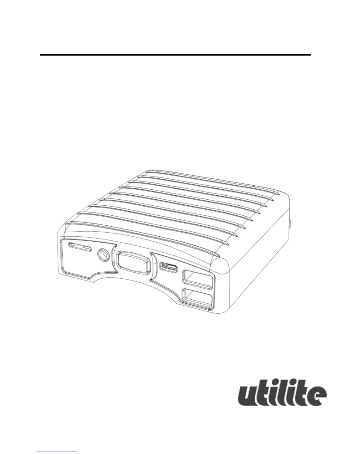
Utilite2
User’s Guide
Page 2

2 December 2014
Contents
Contents ........................................................... 2
Package Contents .......................................... 4
Utilite2 Features .............................................. 5
Utilite2 Overview ............................................. 6
Front View ................................................. 6
Rear View................................................... 6
Getting started with Utilite2 ........................... 7
Connecting a display .................................. 7
Connecting keyboard and mouse .............. 7
Connecting power ..................................... 7
Turning on the system ............................... 7
System login .............................................. 8
Using Utilite2 ................................................... 9
Page 3

December 2014 3
Power button............................................. 9
Power LED.................................................. 9
Audio ......................................................... 9
Debug console ......................................... 10
Utilite2 Maintenance ..................................... 11
Opening bottom cover ............................ 11
Utilite2 service area ................................. 12
Micro-USB mux setting ............................ 12
mSATA socket .......................................... 13
Expansion socket ..................................... 13
Utilite2 Software ............................................ 14
General .................................................... 14
System recovery ...................................... 14
Page 4

4 December 2014
Package Contents
Utilite2 computer
12V DC power supply unit
Power supply AC blade
2x WiFi antenna
User’s guide
Page 5
December 2014 5
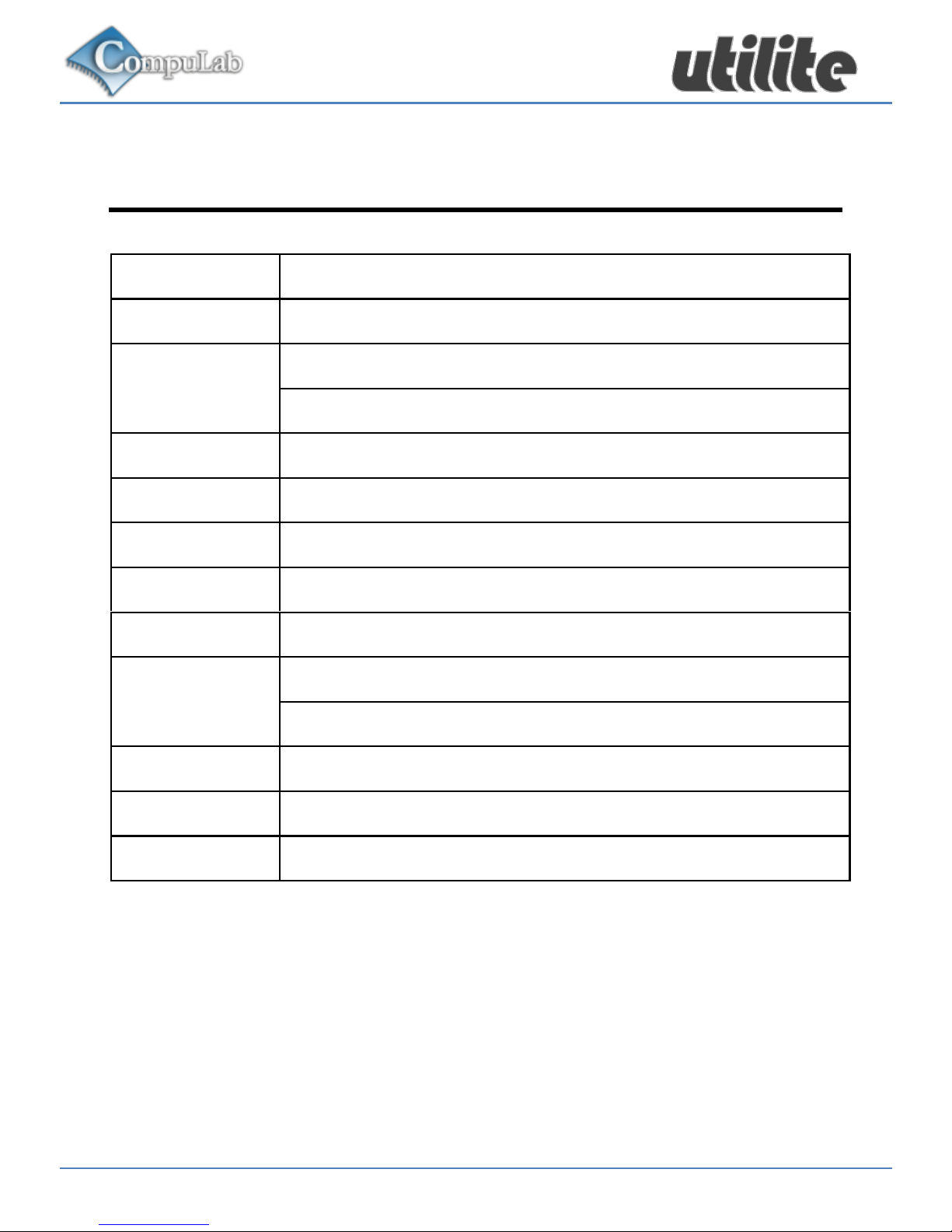
Utilite2 Features
CPU
Qualcomm® Snapdragon™ 600 @1.7GHz
RAM
2GB DDR3
Storage
eMMC 4GB
32GB SSD
(*)
Display
HDMI 1.4 up to 1920 x 1080
LAN
1000 BaseT Ethernet port
WiFi
802.11b/g/n
Bluetooth
Bluetooth 4.0
Audio
Stereo line-out, line-in
USB
Four USB 2.0 480Mbps
USB OTG
SD
Micro-SD socket, SDXC
Serial
Serial debug console via USB connector
Power
12V DC
(*)
Optional feature. Availability depends on Utilite2 model
configuration.
Page 6
6 December 2014
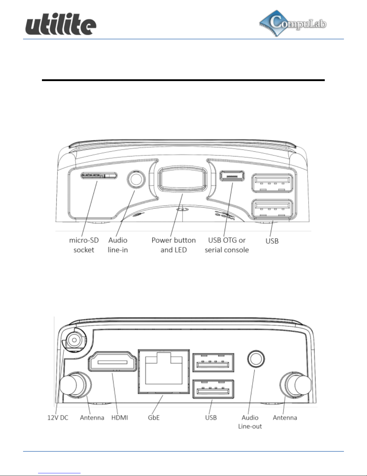
Utilite2 Overview
Front View
Rear View
Page 7

December 2014 7
Getting started with Utilite2
Connecting a display
Connect the display to the Utilite2 HDMI display output using a
standard HDMI cable.
Connecting keyboard and mouse
Connect USB mouse and keyboard devices to the Utilite2 USB
connectors.
Connecting power
Insert the AC power-supply blade into the power supply
unit.
Insert the power supply plug into the Utilite2 12V DC
power jack. Turn the power plug clock-wise to lock the
plug.
Turning on the system
Plug the power supply unit into an AC outlet.
Utilite2 will turn on and boot.
Page 8

8 December 2014
System login
Log into the O/S using the following user details:
Username: utilite
Password: 111111
For root access please use the following credentials:
Username: root
Password: 111111
Page 9

December 2014 9
Using Utilite2
Power button
Utilite2 power button controls the system power state. Pressing
the button for more than 15 seconds, shuts down the system.
Power LED
Utilite2 power LED indicates the system power state. When the
system is active, the LED is green. When the system is shut
down, the LED is orange.
Audio
Standard stereo 3.5mm audio cables should be used to
connect the Utilite2 analog line-out and line-in with external
audio devices.
Page 10

10 December 2014
Debug console
Utilite2 provides an optional debug console interface. The
debug console is multiplexed with the USB OTG interface on
the front-panel micro-USB connector. The multiplexing setting
is controlled by a dedicated, user-accessible jumper. When the
jumper is open (default factory setting), USB OTG is routed to
the micro-USB connector. When the jumper is closed, the
debug console is routed to the connector. To enable debug
console mode, please follow the instructions in the
“Maintenance” section of this document. The debug console is
implemented as a serial-over-USB interface. Connect the
Utilite2 micro-USB connector to a host PC USB port with a
standard micro-USB cable. The debug interface should be
detected as a standard COM port device.
Page 11
December 2014 11
Utilite2 Maintenance
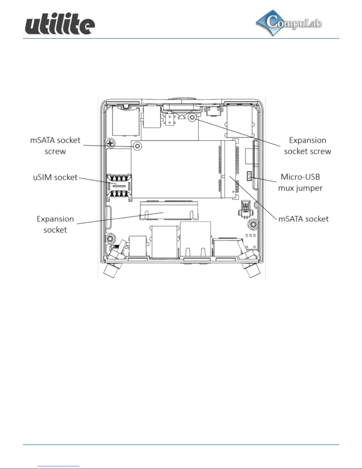
Utilite2 provides user access to micro-USB mux jumper,
mSATA socket and expansion socket through a removable
bottom cover. Utilite2 requires no maintenance. You should not
disassemble Utilite2 other than opening the bottom cover.
Disassembling Utilite2 will void its warranty.
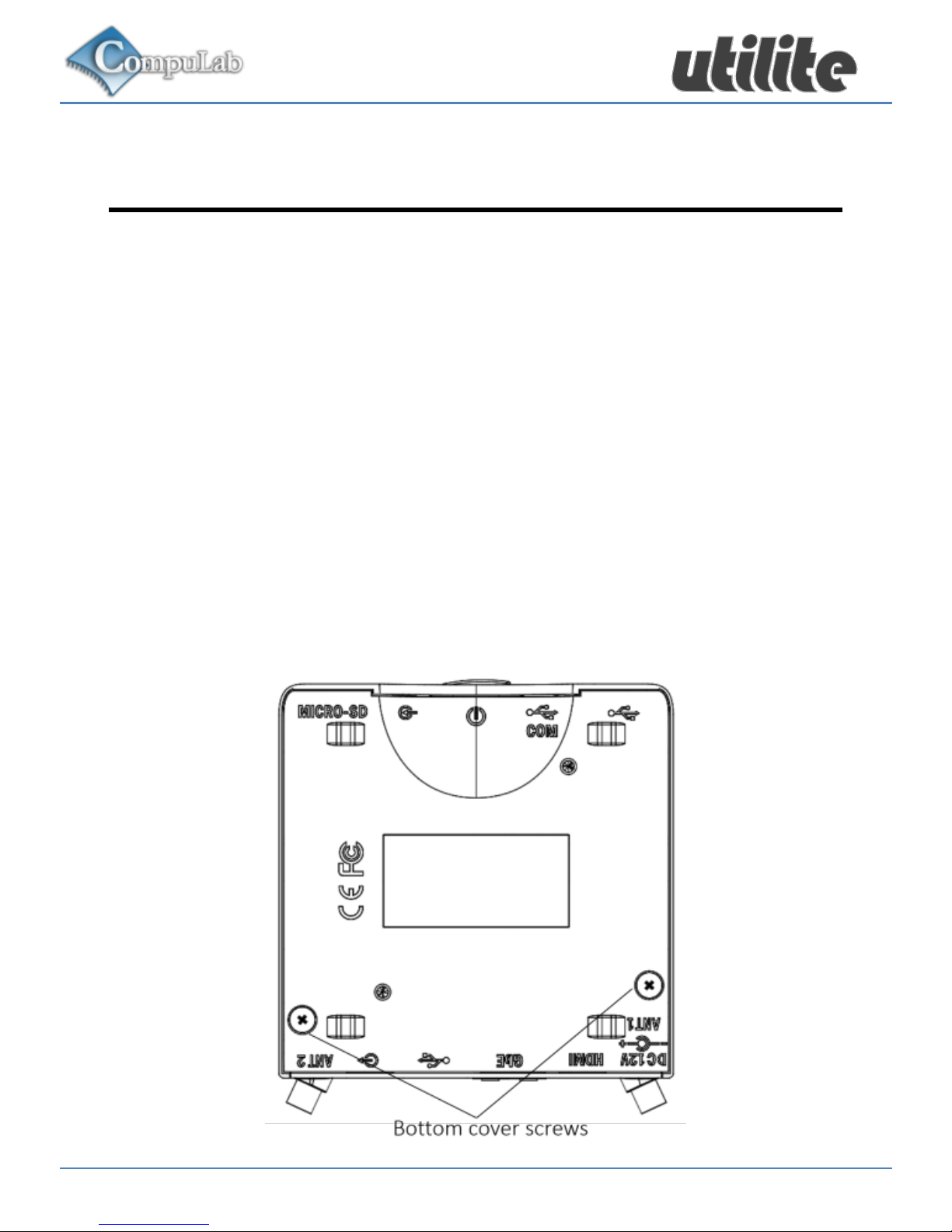
Opening bottom cover
Unscrew the two bottom cover screws shown below.
The bottom cover is now detached. Lift the rear edge of
the cover to remove it completely.
Page 12
12 December 2014
Utilite2 service area
Micro-USB mux setting
The micro-USB multiplexing setting is controlled by the microUSB mux jumper shown above.
Remove the jumper to set the micro-USB connector output
to USB OTG mode.
Assemble the jumper to set the micro-USB connector
output to debug console mode.
Page 13

December 2014 13
mSATA socket
Utilite2 mSATA socket supports standard mSATA storage
cards. This socket does not support mini-PCIe cards.
Install mSATA storage card into the mSATA socket.
Secure the card with the mSATA socket screw.
Expansion socket
Utilite2 expansion socket supports USB cellular modem
modules in mini-PCIe form-factor. Compatible cellular module is
available from CompuLab as a separate cellular kit. The
expansion socket does not support mini-PCIe cards.
Install the modem module into the expansion socket.
Secure the card with the expansion socket screw.
Install uSIM card into the uSIM socket.
Page 14

14 December 2014
Utilite2 Software
General
Utilite2 is a flexible and software-open platform supporting a
variety of operating systems. For further information and
documentation please visit
http://utilite-computer.com/web/support
System recovery
In case of firmware or O/S corruption, Utilite2 design allows full
system recovery by using a downloadable recovery image and
a standard micro-SD card. For recovery instructions please
refer to http://utilite-computer.com/web/support
 Loading...