

Page 1
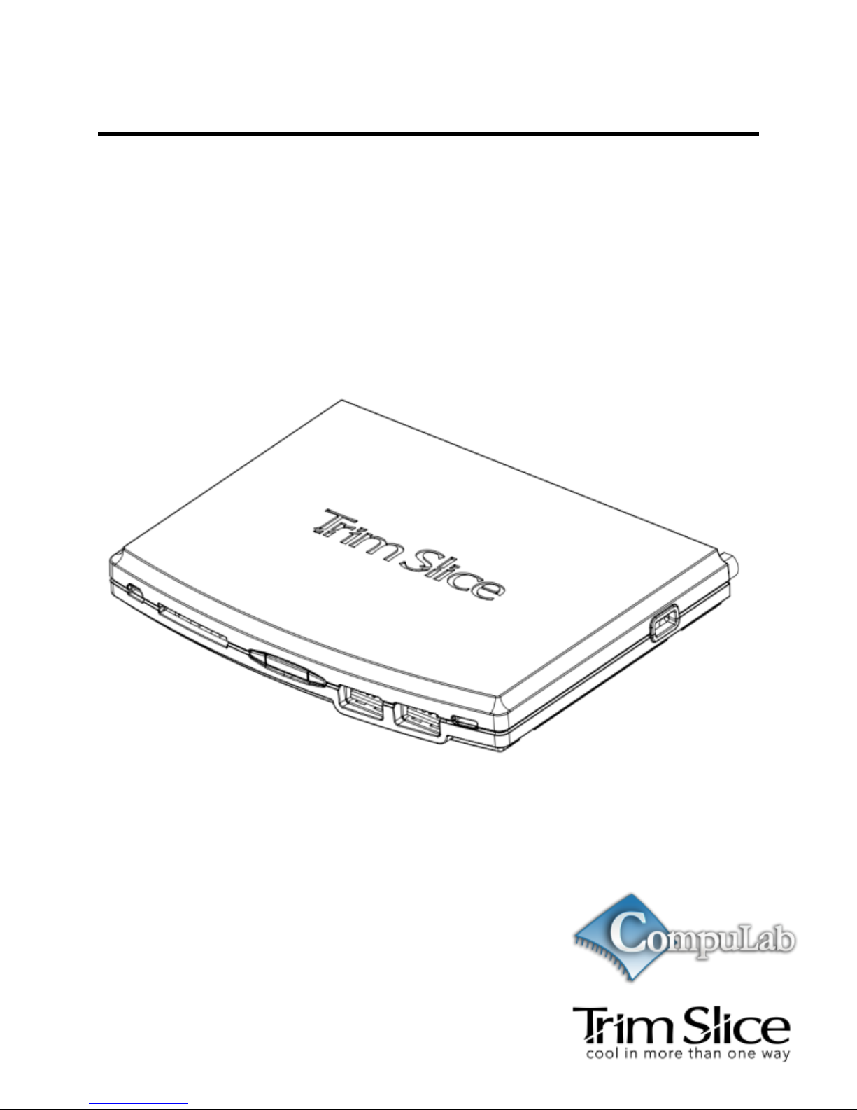
Trim-Slice
User’s Guide
Page 2

2 July 2011
Contents
Contents ............................................................ 2
Package Contents ............................................. 4
Trim-Slice Features ........................................... 5
Trim-Slice Overview .......................................... 6
Front View .................................................. 6
Rear View .................................................. 6
Side View ................................................... 7
Getting started with Trim-Slice .......................... 8
Connecting a display ................................. 8
Connecting keyboard and mouse .............. 8
Connecting power ...................................... 9
Turning on the system ............................. 10
System login ............................................ 10
Using Trim-Slice .............................................. 11
Power button............................................ 11
Page 3

July 2011 3
Power LED............................................... 11
Audio ........................................................ 11
Serial port ................................................ 12
Micro-SD card .......................................... 12
Video input ............................................... 13
Wireless USB adapters ........................... 13
Trim-Slice Software ......................................... 14
General .................................................... 14
Boot-loader .............................................. 14
System recovery ...................................... 15
Page 4

4 July 2011
Package Contents
Trim-Slice computer
12V DC power supply unit
Power supply AC blade
HDMI to DVI adapter cable
Mini serial to DB-9 adapter cable
3.5mm to RCA adapter cable
WiFi antenna
(*)
User’s guide
(*)
Optional item. Availability depends on Trim-Slice model
configuration.
Page 5
July 2011 5
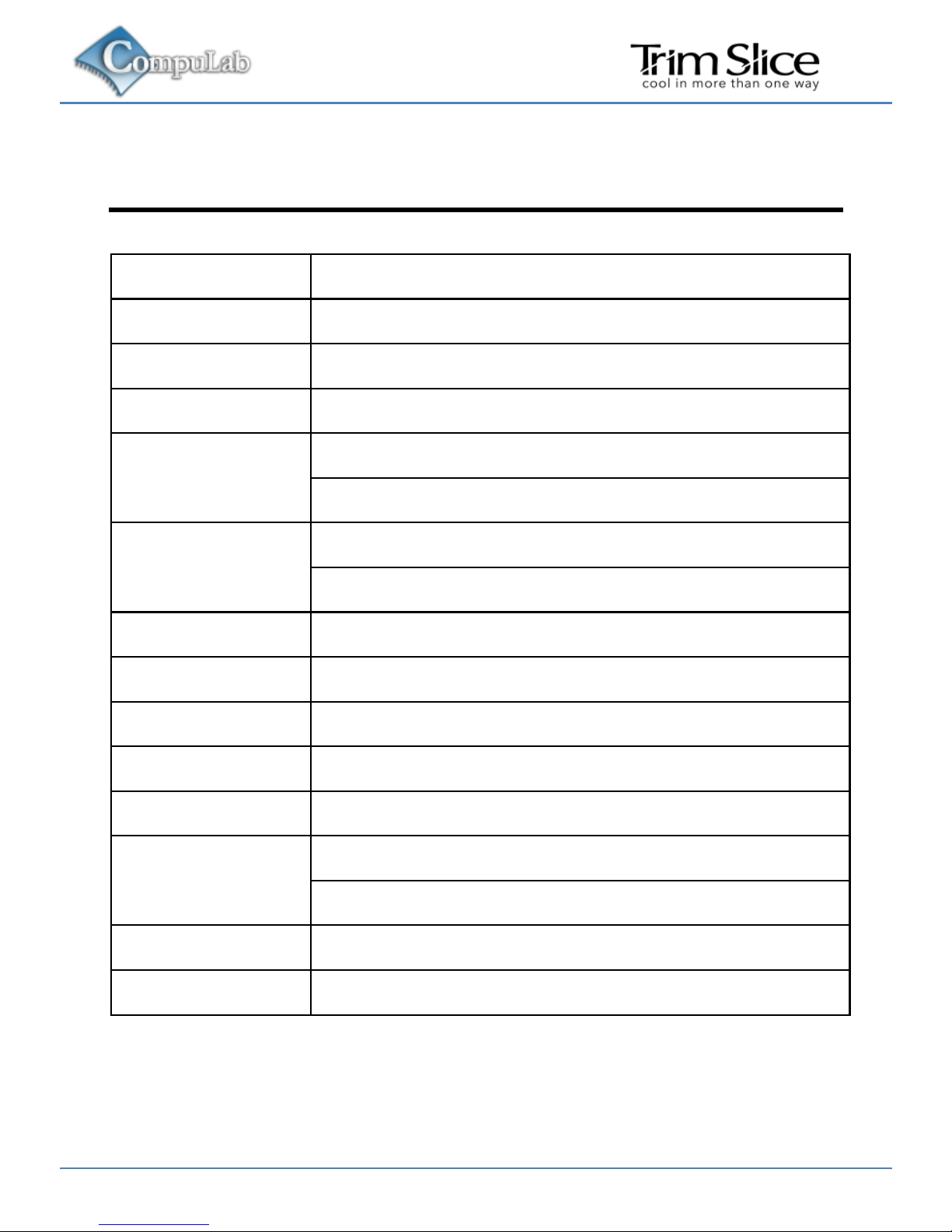
Trim-Slice Features
CPU
NVIDIA Tegra2
GPU
Ultra low-power GeForce
RAM
1GB DDR2-800
Storage
32GB SSD
(*)
Display
HDMI 1.3 1920 x 1080
DVI 1680 x 1050
(*)
Audio
S/PDIF 5.1 channels
Stereo line-out, line-in
Video input
Composite analog NTSC / PAL
(*)
WiFi
802.11n, modular
(*)
Bluetooth
Bluetooth V2.1+EDR, modular
(*)
Ethernet
1000 BaseT Ethernet
USB
4 ports USB 2.0 480Mbps
SD
Full-size SD socket, SDHC
Micro-SD socket, SDHC
Serial
RS232
Power
12V DC
(*)
Optional feature. Availability depends on Trim-Slice model
configuration.
Page 6
6 July 2011
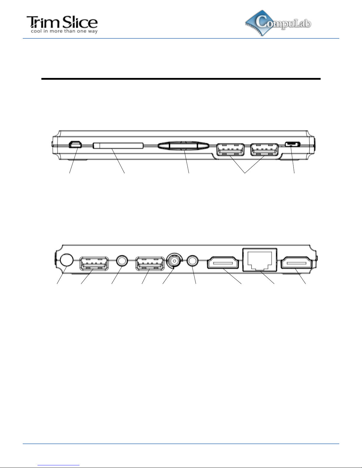
Trim-Slice Overview
Front View
RS-232
SD card slot
USB portsPower button Micro USB
Rear View
WiFi USB GbE
Line-out
Video-in
USB
S/PDIF
Line-in
DVI-D
secondary
DC
12V
HDMI
primary
Page 7
July 2011 7
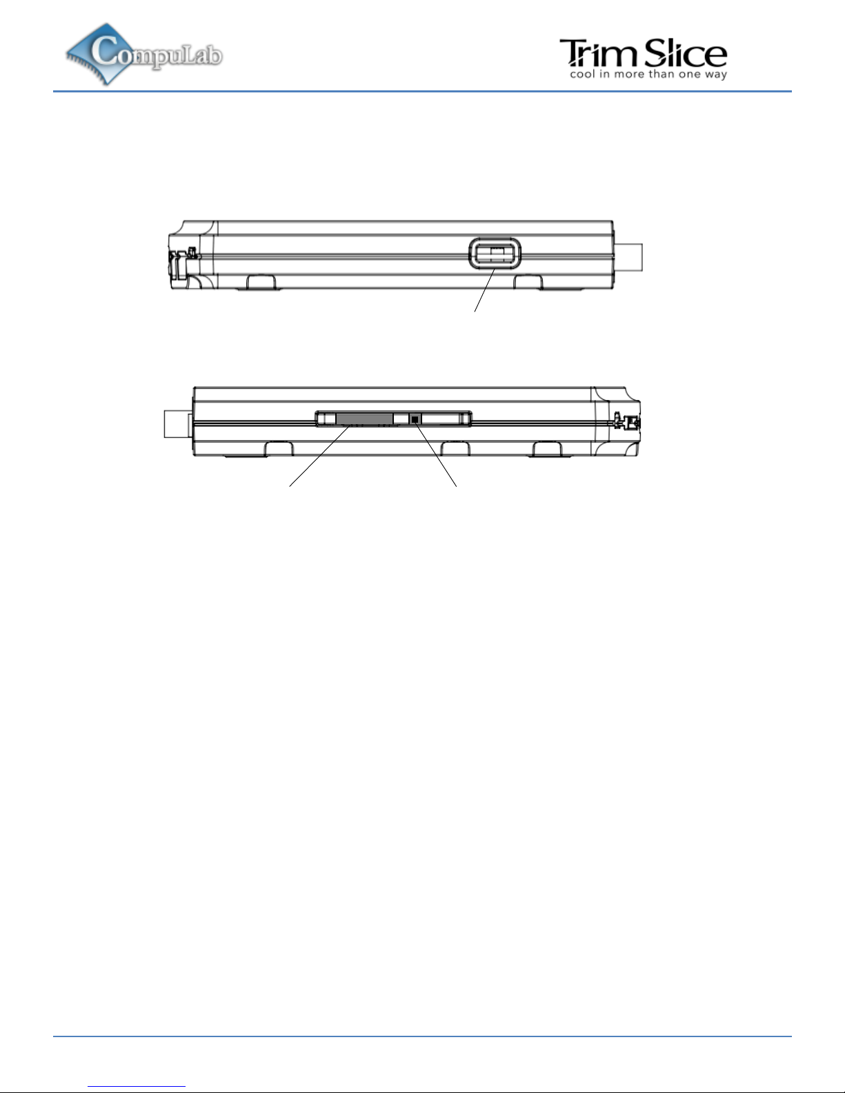
Side View
Kensington lock
Micro-SD
slot
Recovery-boot
button
Page 8

8 July 2011
Getting started with Trim-Slice
Connecting a display
HDMI display
Connect the display to the Trim-Slice HDMI primary display
output using a standard HDMI cable.
DVI display
Connect the display to the Trim-Slice HDMI primary display
output using a standard DVI cable and the HDMI to DVI adapter
included in this package.
Connecting keyboard and mouse
Connect USB mouse and keyboard devices to the Trim-Slice
USB connectors.
Page 9
July 2011 9
Connecting power
Insert the AC power-supply blade into the power supply
unit.
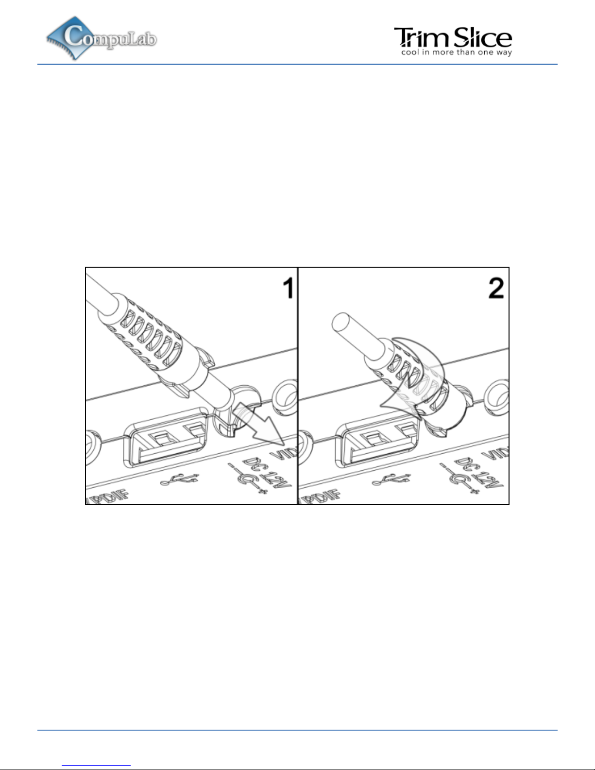
Insert the power supply plug into the Trim-Slice power
jack. Turn the power plug clock-wise to lock the plug.
Page 10

10 July 2011
Turning on the system
Plug the power supply unit into an AC outlet.
Trim-Slice will turn on and boot.
System login
Log into the O/S using the following user details:
Username: trim
Password: 111111
Page 11

July 2011 11
Using Trim-Slice
Power button
The Trim-Slice power button controls the system power state.
Pressing the button for more than 5 seconds, shuts down the
system. When the system is shut down, pressing the power
button turns on the Trim-Slice.
Power LED
The Trim-Slice power LED indicates the system power state.
When the system is active, the LED is on. When the system is
shut down, the LED flashes briefly, once every 4 seconds.
Audio
Analog audio
Standard stereo 3.5mm audio cables should be used to
connect the Trim-Slice analog line-out and line-in with external
audio devices.
S/PDIF
The Trim-Slice S/PDIF output is implemented on the additional
pin of the line-in audio jack. Use the 3.5mm to RCA adapter
included in this package and a standard RCA cable to connect
the Trim-Slice to an external S/PDIF device.
Page 12
12 July 2011
Serial port
Use the mini serial to DB-9 adapter included in this package
and a standard null-modem cable to connect the Trim-Slice RS232 port to a PC serial port.
Micro-SD card
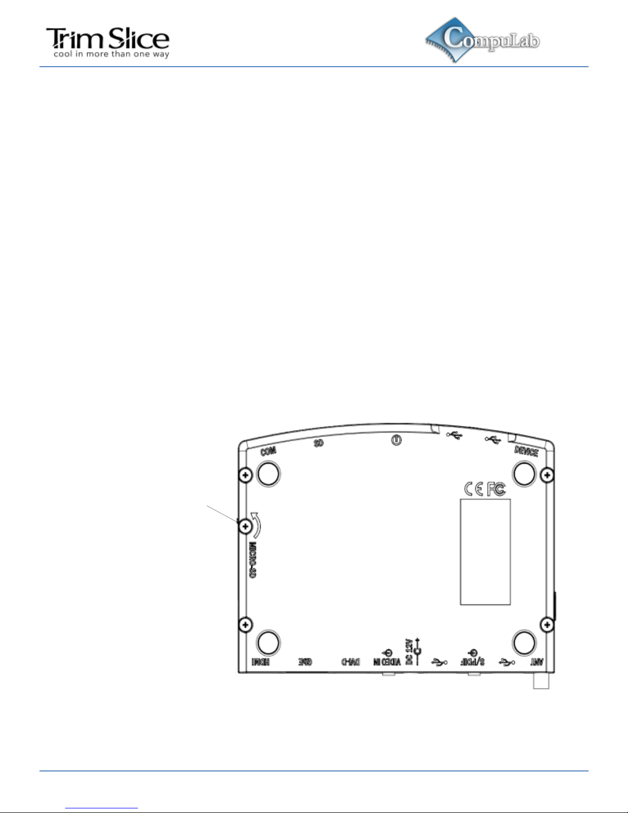
Open the micro-SD security door screw shown below. Open the
security door. Insert the micro-SD card (card contacts facing
up) into the socket.
Micro-SD security
door screw
Page 13

July 2011 13
Video input
The Trim-Slice video input is implemented on the additional pin
of the line-out audio jack. Use the 3.5mm to RCA adapter
included in this package and a standard RCA cable to connect
the Trim-Slice to an external analog video source.
Wireless USB adapters
Wireless USB adapters with miniature internal antennas may
exhibit poor signal quality when plugged directly into Trim-Slice
USB ports. For better signal quality it is recommended to use
the type-A USB extender cable in order to distance wireless
USB adapters from the Trim-Slice enclosure.
Page 14

14 July 2011
Trim-Slice Software
General
The Trim-Slice is a flexible and software-open platform
supporting a variety of operating systems. For further
information and documentation please visit
http://trimslice.com/web/support
Boot-loader
The Trim-Slice utilizes U-Boot as the system boot-loader
responsible for initializing the system and loading the O/S. The
U-Boot is a flexible, feature-rich, open-source boot-loader used
in a broad range of embedded devices. For further information
please refer to the links below:
http://trimslice.com/web/support
http://www.denx.de
Page 15

July 2011 15
System recovery
In case of firmware or O/S corruption, the Trim-Slice design
allows full system recovery by using a downloadable recovery
image and a standard SD card. For recovery instructions
please refer to
http://trimslice.com/web/support
Page 16

16 July 2011
Trim-Slice
Manufacturer: CompuLab Ltd.
This device complies with Part
15 of the FCC Rules.
Operation is subject to the
following two conditions:
(1) This device may not cause
harmful interference, and
(2) This device must accept any
interference received, including
interference that may cause
undesired operation.
Statement
Changes or modifications to this
equipment not expressly
approved by the party
responsible for compliance
(CompuLab Ltd.) could void the
user’s authority to operate the
equipment.
Statement
NOTE: This equipment has been tested and
found to comply with the limits for a Class B
digital device, pursuant to part 15 of the FCC
Rules. These limits are designed to provide
reasonable protection against harmful
interference in a residential installation. This
equipment generates, uses and can radiate
radio frequency energy and, if not installed and
used in accordance with the instructions, may
cause harmful interference to radio
communications. However, there is no
guarantee that interference will not occur in a
particular installation. If this equipment does
cause harmful interference to radio or
television reception, which can be determined
by turning the equipment off and on, the user is
encouraged to try to correct the interference by
one or more of the following measures:
-Reorient or relocate the receiving antenna.
-Increase the separation between the
equipment and receiver.
-Connect the equipment into an outlet on a
circuit different from that to which the receiver
is connected.
-Consult the dealer or an experienced radio/TV
technician for help.
 Loading...