

Page 1

SBC-FITPC2i
Single-Board PC
Reference Guide
1
Page 2

Table of Contents
1. Revision Notes.............................................................................................................3
2. Overview...................................................................................................................... 4
2.1. H
2.2. F
3. System Components....................................................................................................6
3.1. I
3.2. C
3.3. G
3.4. A
3.5. P
3.6. W
4. Peripheral Interfaces & Connectors .......................................................................12
4.1. USB I
4.2. MMC/SDIO/SD (P7)..........................................................................................13
4.3. HDMI C
4.4. M
4.5. A
4.6. S
4.7. LAN P
4.8. S
4.9. LED’
4.10. C
4.11. E
5. Mechanical Considerations and Connectors’ Location......................................... 20
IGHLIGHTS
EATURES
NTEL ATOM
HIPSET
RAPHICS SYSTEM
UDIO SYSTEM
OWER SYSTEM AND POWER CONSUMPTION
ATCHDOG
AIN POWER CONNECTOR
UDIO INTERFACE
ERIAL
ERIAL
ONSUMER INFRARED RECEIVER
XTENSION CONNECTOR FOR
..........................................................................................................4
..............................................................................................................5
CPU .................................................................................................6
.................................................................................................................7
................................................................................................7
.....................................................................................................7
.........................................................................................................11
NTERFACE
ONNECTOR
ATA I
ORTS
COM P
S AND PUSH BUTTONS
(P1, P2, U27, P37, P32)...........................................................12
(J14)....................................................................................13
(J8, P29)...................................................................14
(P4, P9).................................................................................15
NTERFACE
(P26)...............................................................................................17
ORT
.....................................................................................15
(P17, P41) ...........................................................................17
................................................................................18
........................................................................18
RST, GPIO, I2C, LPC
........................................................9
BUS
(P16) .........................18
6. Operating Temperature Ranges..............................................................................23
2
Page 3

1. Revision Notes
22-Feb-2009 Initial release SBC-FITPC2i Rev 1.2
15-Apr-2010 Audio subsystem reviewed
USB connector P37 added
5-Aug-2010 Mini-PCI Express slot removed
3
Page 4

2. Overview
2.1. Highlights
Full-featured PC single board computer, tiny
and power saving
CPU
Intel US15W chipset
Up to 2GB DDR2
DVI Digital display interface, up to
1920x1080
LVDS interface
Serial ATA interface
Bootable onboard solid-state disk (SSD)
Analog audio: line input/output, mic in
Coaxial S/PDIF output
Two 1000BASE-T Ethernet port
802.11b/g/n WiFi
7 x USB 2.0 ports
miniSD Card socket
Serial COM port, RS-232 signalling
Consumer IR receiver
Watchdog
GPIOs
LPC and I2C extension buses
Phoenix BIOS
Single 12V supply, 6-9.6W, fanless operation
Dimensions - 104 x 100.7 x 22.9 mm
Runs Windows XP, Windows 7 and Linux
Also available as a fit-PC2i computer with
enclosure and hard disk.
The SBC-FITPC2i is a tiny,
single board PC based on Intel's
Atom processor and US15W
chipset. It runs all standard
operating systems and software
packages. The SBC-FITPC2i's
unique advantages include
exceptionally small size, quiet,
fanless operation and very low
power consumption.
The rich feature set of the SBCFITPC2i is customizable
according to the price /
performance targets of the user's
application. It makes an ideal
platform for implementation
applications such as home
entertainment and point-of-sale.
4
Page 5

2.2. Features
"Option" column specifies the configuration code required to control the particular feature.
"+" means that the feature is available always.
Feature
Intel Atom Processor: [email protected] 533MHz FSB or
CPU
Chipset
Memory
SSD Bootable onboard Solid-State Disk N
Display interface SDVO-based DVI interface. Hot plug support.
Audio
Ethernet
HDD Interface
Serial COM port RS-232 serial port Y
WiFi
USB
Infrared
BIOS
SDIO/LVDS
GPIOs 3 GPIOs are available +
[email protected] 400MHz FSB. L2: 512KB (dynamic
sizing), L1: 32KB IC, 24KB DC. Intel Deep Power Down
(C6) technology support
Poulsbo US15 Intel System Controller Hub (INTEL SCH)
1GB or 2GB DDR2, 533/400 MHz, 64-bit
Realtek ALC260, High Definition Audio, Line Out, Line In,
Microphone In.
Up to two integrated Gigabit PCI-Express controllers
Realtek RTL8111
SATA-II, using Marvell 88SA8052
802.11 b/g capabilities, Ralink chipset. Up to 54 Mbps, 2.4
GHz band.
4 external USB ports + 3 additional onboard connectors:
data rate up to 480 Mb/s
USB based consumer infra red receiver
Phoenix SecureCore BIOS
MiniSD Card connector supporting SDIO1.1 and MMC4.1
LVDS connector
Specifications
Option
C
+
D
+
A
E
S
W
+
+
+
L
I
5
Page 6

Electrical, Mechanical and Environmental Specifications
Active consumption All contents, excluding off-board components 6-9.6 W
Sleep consumption 0.7-1.2 W, depending on configuration and mode
Dimensions
Weight 90 g
MTBF > 100,000 hours
Operation
temperature
Storage temperature -40o to 85o C
Relative humidity
104 x 96 mm, not including connectors, 104x100.7 including
connectors and buttons. Height: 22.9mm
Commercial: 0o to 70o C
Extended: -20o to 70o C
Industrial: -40o to 85o C
* specified for board only, measured on component case
* industrial and extended temperature certifications are not
applicable for RTC backup battery
10% to 90% (operation)
05% to 95% (storage)
3. System Components
3.1. Intel Atom CPU
The SBC-FitPC2i utilizes an Intel® Atom Z5xx series CPU.
The Intel® Atom Z5xx series processor is built on 45-nanometer process technology — the
first generation of low-power IA-32 micro-architecture specially designed for the new class
of Mobile Internet Devices (MID).
The following list provides some of the key features on this processor:
• New single-core processor for mobile devices with enhanced performance
• On die, primary 32-kB instructions cache and 24-kB write-back data cache
• 100-MHz and 133-MHz Source-Synchronous front side bus (FSB)
• Supports Hyper-Threading Technology 2-threads
• On die 512-kB, 8-way L2 cache
• Support for IA 32-bit and Intel® 64 architecture
• Intel® Virtualization Technology (Intel® VT)
• Intel® Streaming SIMD Extensions 2 and 3 (Intel® SSE2 and Intel® SSE3) and
Supplemental Streaming SIMD Extensions 3 (SSSE3) support
6
Page 7

• Supports new CMOS FSB signaling for reduced power
• Micro-FCBGA8 packaging technologies
• Thermal management support via TM1 and TM2
• FSB Lane Reversal for flexible routing
• Supports C0/C1(e)/C2(e)/C4(e)
• New C6 Deep Power Down Technology
• L2 Dynamic Cache Sizing
• New Split-VTT support for lowest processor power state
• Advanced power management features including Enhanced Intel SpeedStep®
Technology
• Execute Disable Bit support for enhanced security
3.2. Chipset
The SBC-FitPC2i uses an Intel® System Controller Hub (Intel® SCH) US15W chipset.
The Intel® SCH chipset component of the Atom low power platform, combines
functionality normally found in separate GMCH (integrated graphics, processor interface,
memory controller) and ICH (on-board and end-user I/O expansion) components into a
single component consuming less than 2.3 W of thermal design power.
3.3. Graphics System
The SBC-FitPC2i graphics system is based on the Intel® SCH integrated graphics
controller, based on Intel® GMA500 architecture. The SBC-FitPC2i board features an
HDMI connector (J14) providing DVI output. DVI output is formed using a Chrontel
CH7307C DVI transmitter in revisions 1.2 and 1.2x.
Graphics Controller Description:
The Intel SCH provides integrated graphics (2D and 3D) and high-definition video decode
capabilities with minimal power consumption.
The highly compact IGD contains advanced shader architecture (model 3.0+) that performs
pixel shading and vertex shading within a single hardware accelerator. The processing of
pixels is deferred until they are determined to be visible, which minimizes access to
memory and improves render performance.
The Intel SCH supports full hardware acceleration of video decode standards such as
H.264, MPEG2, MPEG4, VC1, and WMV9.
3.4. Audio System
7
Page 8

The audio system of the SBC-FitPC2i is implemented using Realtek ALC662 – a 5.1
channel high-definition audio codec chip in a 2-channel mode.
• The line stereo output connects to the on-board audio jack (P9).
• The line-in and microphone inputs are connected together to a 3.5mm audio jack (P4).
Audio Specifications:
Parameter Min Typ Max Units
Full Scale Input Voltage
All Inputs (gain=0dB)
All ADC
Full Scale Output Voltage
All DAC
S/N (A Weighted)
Headphone amp
ADC
DAC
THD+N
Headphone amp (32 Ohm load)
ADC
DAC
Frequency Response
ADC, DAC
Crosstalk Between Output Channels
1kHz
20 kHz
-
-
-
-
-
-
-
-
-
20000 -
-
-
1.6
1.4
1.4 -
98
90
98
-75
-85
-92
-90
-80
-
-
Vrms
Vrms
Vrms
-
-
-
-
-
-
-
-
-
dB FSA
dB FSA
dB FSA
dB FS
dB FS
dB FS
Hz
dB
dB
Input Impedance (gain=0dB) 40 kOhm
Output Impedance
Line Output
-
100 -
Ohm
8
Page 9

3.5. Power System and Power Consumption
The SBC-FitPC2i is designed to work with a large range of power sources. It provides
stable system functionality with input voltage in the range of 7.5V-15V. An unregulated
power supply may be used as long as peaks of supply voltage don’t exceed the input
voltage range.
Power Modes and Power Consumption
There are three typical working modes: Off, Suspend to RAM (STR) and Full Operating
mode.
During Full Operating mode, power consumption may vary depending on both the
software installed on the system and on the CPU / system load.
Current consumption
Measuring conditions: Vin = 12V, no peripheral devices connected
Mode Min Max
Off 70mA 90mA
Suspend to RAM 70mA 100mA
Full Operating 0.45A 0.8A
Backup Power for RTC and CMOS memory
The SBC-FitPC2i implements backup power for RTC and CMOS settings. There is an onboard rechargeable Li-AL battery, 18mAh. The battery is constantly charged while the
power supply is connected. The RTC will retain system time and CMOS setting for at
least 100 days when the system is unpowered (as long as the system was connected to a
power supply for at least 24 hours prior to power-down).
It’s possible to reset CMOS data to default shorting J4B2 connector pins for several
seconds once the system is unpowered.
Power Supply for USB Devices
The SBC-FitPC2i has 6 USB ports, each one capable of providing up to 500mA. Total
power consumption from USB ports should not exceed 1.5A.
Wake-up Events
The system can wake-up from STR state by the following events:
• On/Off button
• RTC
• USB keyboard/mouse activity
9
Page 10

Note: USB and RTC wakeup events are available only with BIOS from 21-Jul-2009 or
later.
In order to enable wake on USB keyboard / mouse in Windows XP, do the following:
• Open REGEDIT
• Create a new key called HKLM\System\CurrentControlSet\USB
• Create a new DWORD value HKLM\System\CurrentControlSet\USB\USBBIOSx and
set it to 00000000
Restart the computer
The Power management TAB in HID should be available - check “bringing device out of
the standby” option.
10
Page 11

3.6. Watchdog
The SBC-FitPC2i implements watchdog timer using 8-bit count-down timer clocked by
1Hz. Watchdog generates system-reset event when the counter reaches zero.
Note: watchdog functionality is available only with BIOS from 21-Jul-2009 or later.
Operation
Using watchdog requires an appropriate driver to be installed before enabling a watchdog
in BIOS. To enable or disable the watchdog enter BIOS Setup (F2), go to "Advanced"
menu and change "Watchdog Timer" option to On/Off accordingly. Once the "Watchdog
Timer" option enabled the timeout can be set 31-255 seconds. Entering setup temporary
disables watchdog operation regardless to current state.
Reference code
/*This code will work in DOS only.*/
void SendData( unsigned char command ,unsigned char data )
{
outp(0x4c,command);
delay(100);
outp(0x48,data);
delay(200);
}
/*Set watchdog timeout.
This function must be called before timeout ends to prevent system reset. */
void EnableWatchd(unsigned char time)
{
SendData(1,1);
SendData(2,time);
}
void DisableWatchd()
{
SendData(1,0);
SendData(2,0);
}
11
Page 12

4. Peripheral Interfaces & Connectors
4.1. USB Interface (P1, P2, U27, P37, P32)
The SBC-FitPC2i USB provides a total of 7 USB ports. The USB interface is provided
directly by Intel® SCH USB controller that implements UHCI and EHCI host controller
architecture and complies with USB 1.1 and 2.0 standards.
Connectors P1, P2 - miniUSB type AB:
Pin Name
1 USB_VCC
2 USB_N
3 USB_P
4 N/C
5 GND
Connectors P38, P40 – shrouded headers for internal add-indevices:
Pin Name
1 USB_VCC (3.3V)
2 USB_N
3 USB_P
4 GND
5 LED (DS2) Enable#
6 N/C
Note: P38 and P40 provide 3.3V as a USB_VCC.
Note: P40 is routed to the same port as P32 pins 5..8.
Note: USB port on connectors P40 and P38 are connected to the EHCI USB 2.0 controller
only. Therefore they will only work with high-speed devices (480Mbps) such as storage
devices, advanced cameras, etc.
Connector U27 – USB, dual stacked type A connector. Optionally may be installed lowprofile single USB connector P37.
Pin Name
1 USB_VCC
2 USB_N
3 USB_P
4 GND
Connector P32 – optional USB dual-port 100-mil header:
Pin Name
12
Page 13
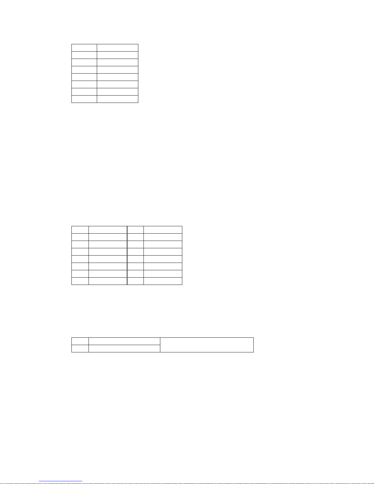
1 USB_VCC
2 USB_N
3 USB_P
4 GND
5 USB_VCC
6 USB_N
7 USB_P
8 GND
Note: USB port on connector P32 pins 5..8 is connected to the EHCI USB 2.0 controller
only. Therefore it works only with high-speed devices (480Mbps) such as storage devices,
advanced cameras, etc.
4.2. MMC/SDIO/SD (P7)
The SBC-FitPC2i MMC/SDIO/SD interface is based on the SDIO controller of the Intel®
SCH chipset.
The controller supports MMC4.0 and SDIO1.1 specifications. MMC 4.0 transfer rates can
be up to 48 MHz with bus widths of 1 or 4 bits. SDIO 1.1 supports transfer rates of up to
24 MHz and bus widths of 1 or 4 bits.
The MMC controller signals are routed to the on-board mini-SD socket (P7).
Connector P7, standard mini-SDIO socket:
Pin Name Pin Name
1 SD_DAT3 8 SD_DAT1
2 SD_CCMD 9 SD_DAT2
3 GND 10 N/C
4 VCC_SDIO 11 N/C
5 SD_CLK 12 SD_CD
6 GND 13 GND
7 SD_DAT0
4.3. HDMI Connector (J14)
The SBC-FitPC2i provides a DVI interface using an HDMI connector.
Connector J14, standard HDMI-A connector:
Pin Name
1 TMDS_Data2+
13
Page 14
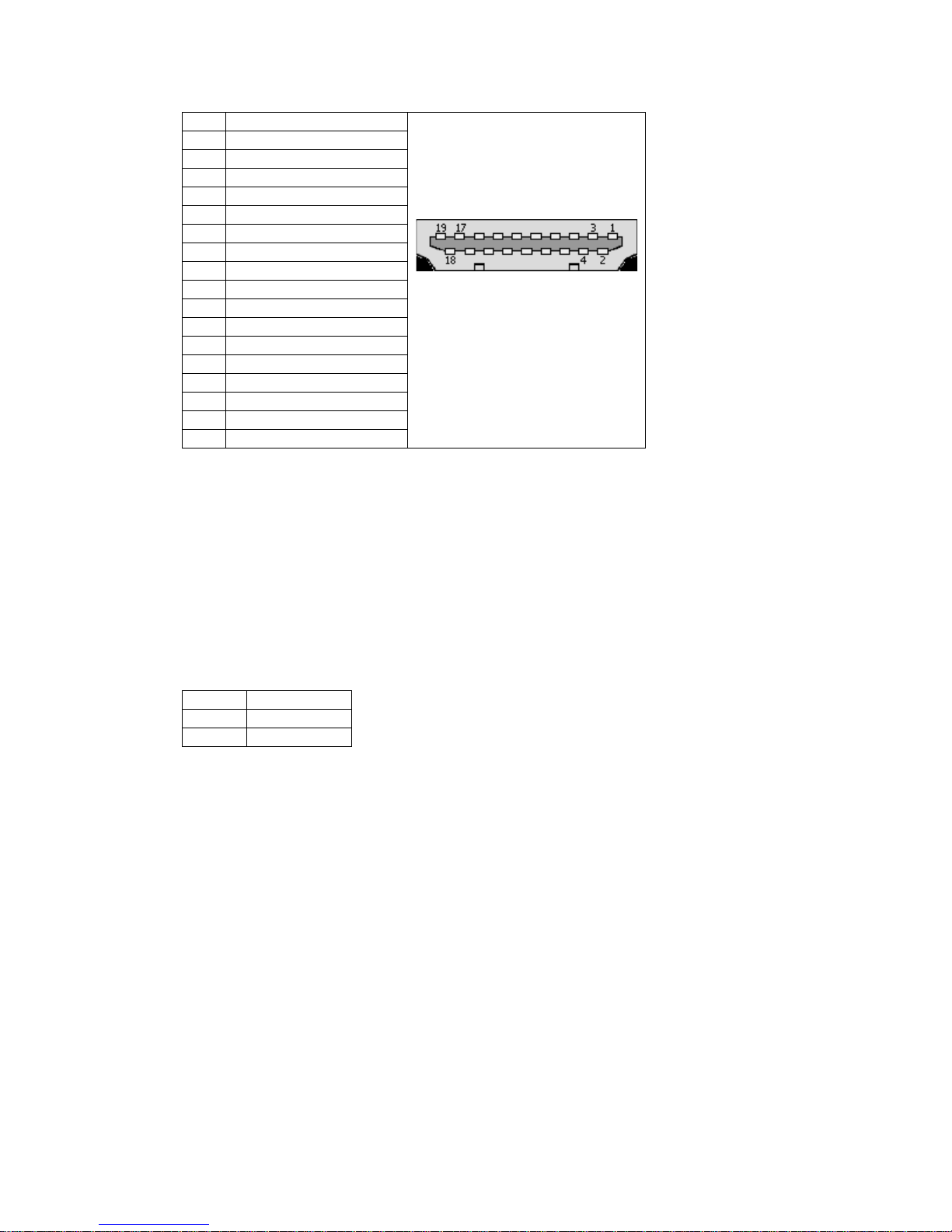
2 GND
3 TMDS_Data24 TMDS_Data1+
5 GND
6 TMDS_Data17 TMDS_Data0+
8 GND
9 TMDS_Data010 TMDS_Clock+
11 GND
12 TMDS_Clock13 N/C
14 N/C
15 DDC_SCL
16 DDC_SDA
17 GND
18 +5 V
19 Hot_Plug_Detect
4.4. Main Power Connector (J8, P29)
The main power connector is a round DC jack with a 3.9mm external diameter and a
1.5mm internal diameter. Outer contact is connected to GND and inner contact to
VCC_IN.
The connector is compatible with the power supply available from CompuLab.
There is an optional 100MIL header (P29), which may be assembled in place of J8.
Connector P29 – optional power header:
Pin Name
1 GND
2 VCC_IN
14
Page 15
4.5. Audio Interface (P4, P9)
The SBC-FitPC2i provides 2-channel high-definition audio. The following interfaces are
provided:
• Stereo line output
• Stereo line/mic input
Each interface is connected to a dedicated 3.5mm jack.
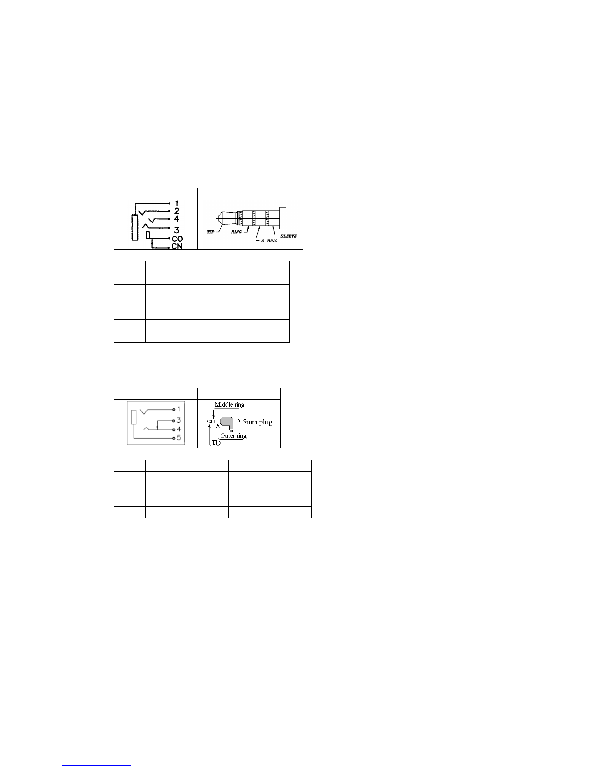
Line out (P9):
Jack pin-out Mating plug
Pin Signal Mating plug pin
1 AGND Sleeve
2 SPDIF out 2nd ring
3 Line out right Ring
4 Line out left Tip
CO N/C CN N/C -
Note: if only the analog stereo output is required with no SPDIF functionality, the same
plug as for P4 may be used.
Line in (P4):
Jack pin-out Mating plug
Pin Signal Mating plug pin
1 Line in/mic left Tip
3 NC -
4 Line in/mic right Middle ring
5 Analog GND Outer ring
4.6. Serial ATA Interface
15
Page 16
This interface is available only in modules with the “S” option. The SBC-FitPC2i serial
ATA (SATA) interface is provided by an Intel® SCH IDE controller and Marvell
88SA8052 SATA bridge.
The SATA host bridge is defined as a slave device on the Intel® SCH controller’s IDE
bus. It supports ATA/ATAPI PIO mode, UDMS mode at transfer rates 16.7 to 150
MB/sec, power-save modes and hot-plug.
A proprietary add-on board called SATA-ADP is used to interface the hard drive to the
SBC-FitPC2i. It connects to 12-pin headers (P30, P31) on SBC-FitPC2i and features a
combo SATA connector providing both data and power for a single 2.5” HDD or SSD.
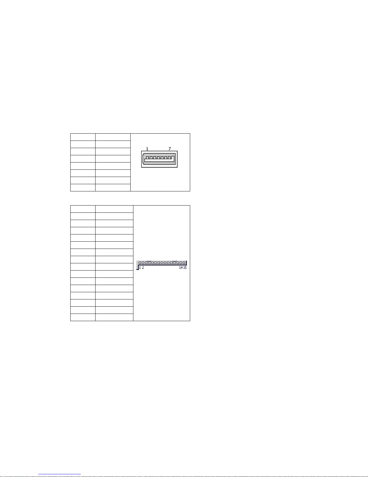
SATA interface, data:
Pin Name
1 GND
2 TX+
3 TX-
4 GND
5 RX6 RX+
7 GND
SATA interface, power:
Pin Name
1 N/C
2 N/C
3 N/C
4 GND
5 GND
6 GND
7 VCC5
8 VCC5
9 VCC5
10 GND
11 GND
12 GND
13 N/C
14 N/C
15 N/C
16
Page 17

4.7. LAN Ports (P26)
The SBC-FitPC2i provides up to two Gigabit Ethernet ports implemented by a Realtek
RTL8111x Gigabit Ethernet controller.
The RTL8111x offers data transmission over a CAT 5 UTP or CAT 3 UTP (10Mbps only)
cable. Functions such as Crossover Detection and Auto-Correction, polarity correction,
adaptive equalization, crosstalk cancellation, echo cancellation, timing recovery and error
correction are implemented to provide robust transmission and reception capability at high
speed. The RTL8111x is compliant with IEEE 802.3u specifications for 10/100Mbps
Ethernet and IEEE 802.3ab specifications for 1000Mbps Ethernet.
The RTL8111x is fully compliant with Microsoft® NDIS5, NDIS6 (IPv4, IPv6, TCP,
UDP) Checksum and Segmentation Task-offload (Large and Giant send) features, and
supports IEEE 802 IP Layer 2 priority encoding and IEEE 802.1Q Virtual bridged Local
Area Network (VLAN).
The Ethernet interface is available through a dual RJ-45 connector P34 or single RJ-45
connector P36.
Pin Name Description
1 BI_DA+ Bi-directional pair A +
2 BI_DA- Bi-directional pair A 3 BI_DB+ Bi-directional pair B +
4 BI_DC+ Bi-directional pair C +
5 BI_DC- Bi-directional pair C 6 BI_DB- Bi-directional pair B 7 BI_DD+ Bi-directional pair D +
8 BI_DD- Bi-directional pair D -
4.8. Serial COM Port (P17, P41)
Ultra mini serial connectors P17 and P41 provide serial connectivity using RS-232
signaling. Interface cable is available from CompuLab.
Pin Name
1 TX
2 RTS
3 RX
4 CTS
5 DTR
6 DSR
7 N/C
8 GND
17
Page 18

4.9. LED’s and Push Buttons
SBC-FitPC2i push buttons
The SBC-FitPC2i features two user-accessible push buttons:
• SW1 is the main system hardware reset button.
• SW2 is the main system power on / off / suspend button.
SBC-FitPC2i LED’s
The following table describes SBC-FitPC2i LED’s:
LED Designation LED activity
DS1 HDD access ON when HDD is accessed
DS2 WiFi Activity Depends on a mini PCI-express
WLAN module. Refer to the WLAN
module datasheet.
DS3 System power ON when the system is in active
state, OFF in suspend-to-RAM and
off states.
4.10. Consumer Infrared Receiver
The SBC-FitPC2i features a Consumer Infrared receiver, based on a programmed micro
controller with USB interface.
4.11. Extension connector for RST, GPIO, I2C, LPC bus (P16)
SBC-FitPC2i provides the ability to connect external devices using extension interface. 40pin 0.5mm pitch FPC connector is used.
Pin Name Pin Name
1 +5V_STBY 21 +3.3V_STBY
2 +5V_STBY 22 RESERVED
3 +5V_STBY 23 RESERVED
4 +5V_STBY 24 GND
5 RESERVED 25 GPIO0
6 GND 26 RESERVED
7 RESERVED 27 GPIO8
8 RESERVED 28 GPIO9
9 GND 29 GND
10 RESET_IN 30 RESERVED
18
Page 19

11 RESERVED 31 RESERVED
12 GND 32 RESERVED
13 SMB_CLK 33 GND
14 SMB_DAT 34 LPC_AD0
15 GND 35 LPC_AD1
16 RESERVED 36 LPC_AD2
17 RESERVED 37 LPC_AD3
18 RESERVED 38 LPC_FRAME
19 +3.3V_STBY 39 GND
20 +3.3V_STBY 40 LPC_CLK
Note: reserved pins must be left unconnected. Connecting them to anything may lead to
system malfunction.
Total allowed consumption from 5V should be less than 500mA,
from 3.3V less than 300 mA
19
Page 20
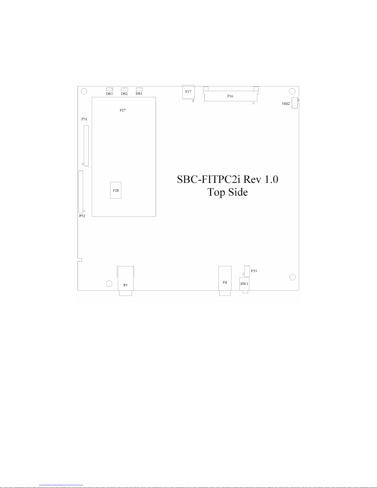
5. Mechanical Considerations and Connectors’ Location
The 3D solidworks model and “dxf” assembly files of the SBC-FitPC2i board may be
downloaded from [Developer] >> [fit-PC2] section of CompuLab’s web-site.
Connectors on the Top Side:
P4 Line In and Mic In 3.5mm audio jack socket
P9 Line Out and S-PDIF Coaxial Out audio jack socket
P16 Debug/Production interface
P17 Mini Serial port connector
P27 Mini PCI Express socket (not available)
P28 Infrared firmware update interface
20
Page 21
P31 Serial ATA interface socket
P32 USB header
P33 Reset header (option)
Other references on the Top Side:
DS1 HDD access LED
DS2 WLAN activity LED
DS3 Power ON LED
SW1 Reset button
J4B2 RTC reset header (option)
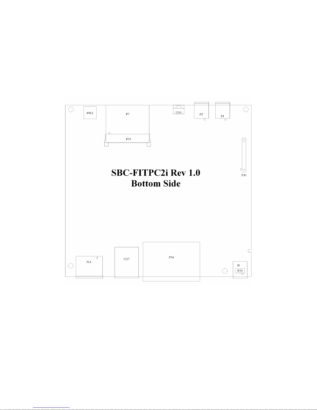
Connectors on the Bottom Side:
J8 Power jack socket (option)
21
Page 22

J14 DVI HDMI-type connector
P1 Mini-USB connector
P2 Mini-USB connector
P7 Mini SD-Card socket (option)
P29 Power header (option)
P30 Serial ATA interface socket (option)
P34 LAN1 and LAN2 connectors
P35 LVDS interface connector (option)
U27 USB stacked connector
Other references on the Bottom Side:
SW2 Power button
U10 Infrared receiver
22
Page 23

6. Operating Temperature Ranges
The information in this section refers to the SBC-FitPC2i board only. For temperature
ranges of off-board components such as the hard disk or WLAN module, please refer to the
component’s datasheet.
The SBC-FitPC2i is available with three options of operating temperature range:
Range Temp. Description
Commercial 0o to 70o C Sample cards from each batch are tested for the lower
and upper temperature limits. Individual cards are not
tested.
Extended -20o to 70o C Every card undergoes a short test for the lower limit
(-20o C) qualification.
Industrial -40o to 85o C Every card is extensively tested for both lower and
upper limits and at several midpoints.
23
 Loading...